Hardware Task Scheduling for Partially Reconfigurable FPGAs George Charitopoulos 1,2 , Iosif Koidis 1,2 , Kyprianos Papadimitriou 1,2 , and Dionisios Pnevmatikatos 1,2 1 Institute of Computer Science, Foundation for Research and Technology – Hellas, Heraklion, Greece 2 School of Electronic and Computer Engineering, Technical University of Crete, Chania, Greece [email protected]Abstract. Partial reconfiguration (PR) of FPGAs can be used to dynamically extend and adapt the functionality of computing systems, swapping in and out HW tasks. To coordinate the on-demand task execution, we propose and implement a run time system manager for scheduling software (SW) tasks on available processor(s) and hardware (HW) tasks on any number of reconfigurable regions of a partially reconfigurable FPGA. Fed with the initial partitioning of the application into tasks, the corresponding task graph, and the available task mappings, the RTSM considers the runtime status of each task and region, e.g. busy, idle, scheduled for reconfiguration/execution etc., to execute tasks. Our RTSM supports task reuse and configuration prefetching to minimize reconfigurations, task movement among regions to efficiently manage the FPGA area, and RR reservation for future reconfiguration and execution. We validate its correctness using our RTSM to execute an image processing application on a ZedBoard platform. We also evaluate its features within a simulation framework, and find that despite the technology limitations, our approach can give promising results in terms of quality of scheduling. 1 Introduction Reconfiguration can dynamically adapt the functionality of hardware systems by swapping in and out HW tasks. To select the proper resource for loading and triggering HW task reconfiguration and execution in partially reconfigurable systems with FPGAs, efficient and flexible runtime system support is needed [6]. In this paper we propose and implement a Run-Time System Manager (RTSM) incorporating efficient scheduling mechanisms that balance effectively the execution of HW and SW tasks and the use of physical resources. We aim to execute as fast as possible a given application, without exhausting the physical resources. Our motivation during the development of RTSM was to find ways to overcome the strict technology restrictions imposed by the Xilinx PR flow [8]: Static partitioning of the reconfigurable surface in reconfigurable regions (RR).
Transcript
Hardware Task Scheduling for Partially
Reconfigurable FPGAs
George Charitopoulos1,2, Iosif Koidis1,2, Kyprianos Papadimitriou1,2,
and Dionisios Pnevmatikatos1,2
1 Institute of Computer Science,
Foundation for Research and Technology – Hellas, Heraklion, Greece 2
Abstract. Partial reconfiguration (PR) of FPGAs can be used to dynamically
extend and adapt the functionality of computing systems, swapping in and out
HW tasks. To coordinate the on-demand task execution, we propose and
implement a run time system manager for scheduling software (SW) tasks on
available processor(s) and hardware (HW) tasks on any number of
reconfigurable regions of a partially reconfigurable FPGA. Fed with the initial
partitioning of the application into tasks, the corresponding task graph, and the
available task mappings, the RTSM considers the runtime status of each task
and region, e.g. busy, idle, scheduled for reconfiguration/execution etc., to
execute tasks. Our RTSM supports task reuse and configuration prefetching to
minimize reconfigurations, task movement among regions to efficiently manage
the FPGA area, and RR reservation for future reconfiguration and execution.
We validate its correctness using our RTSM to execute an image processing
application on a ZedBoard platform. We also evaluate its features within a
simulation framework, and find that despite the technology limitations, our
approach can give promising results in terms of quality of scheduling.
1 Introduction
Reconfiguration can dynamically adapt the functionality of hardware systems by
swapping in and out HW tasks. To select the proper resource for loading and
triggering HW task reconfiguration and execution in partially reconfigurable systems
with FPGAs, efficient and flexible runtime system support is needed [6]. In this paper
we propose and implement a Run-Time System Manager (RTSM) incorporating
efficient scheduling mechanisms that balance effectively the execution of HW and
SW tasks and the use of physical resources. We aim to execute as fast as possible a
given application, without exhausting the physical resources.
Our motivation during the development of RTSM was to find ways to overcome
the strict technology restrictions imposed by the Xilinx PR flow [8]:
Static partitioning of the reconfigurable surface in reconfigurable regions (RR).
Reconfigurable regions can only accommodate particular hardware core(s), called
reconfigurable modules (RM). The RM-RR binding takes place at compile-time,
after sizing and shaping properly the RR.
An RR can hold one RM only at any point of time, so a second RM cannot be
configured into the same RR even if there are enough free logic resources for it.
Our RTSM runs on Linux x86-based systems with a PCIe FPGA board, e.g. XUP
V5, or on embedded processors (Microblaze or ARM) within the FPGA; it can be used
on other processors and FPGAs. We validated the behavior of RTSM on a fully
functional system on a ZedBoard platform executing an edge detection application [7].
We also created a simulation framework that incorporates current technology
restrictions in order to evaluate our RTSM. The main contributions of this work are:
an RTSM with portable functionality in its main core, capable to control HW and
SW tasks in PR FPGA-based systems;
dynamic execution of complex task graphs, with forks, joins, loops and branches;
combination of different scheduling policies, such as relocation, reuse,
configuration prefetching, reservation and Best Fit.
In the following two sections, we first discuss previous work in the field, and then
we present the key concepts and provide details on the RTSM input and operation.
Then, in Section 4 we offer a performance evaluation in a simulation environment and
validation on a real FPGA-based system, and in Section 5 we summarize the paper..
2 Related Work
In one of the first works on hardware task scheduling for PR FPGAs, Steiger et al.
addressed the problem for the 1D and 2D area models by proposing two heuristics;
Horizon and Stuffing [1]. Marconi et al. were inspired by [1] and presented a novel 3D
total contiguous surface heuristic in order to equip the scheduler with “blocking-
awareness” capability [2]. Subsequently, Lu et al. created the first scheduling
algorithm that considers the data dependencies and communication amongst hardware
tasks, and between tasks and external devices [3].
Efficient placement and free space management algorithms are equally important.
Bazargan et al. [4], offers methods and heuristics for fast and effective on-line and
off-line placement of templates on reconfigurable computing systems. Compton et al.,
in a fundamental work in the field of task placement, proposed run-time partitioning
and creation of new RRs in the FPGA [5]. However, the proposed transformations are
still beyond the currently supported FPGA technology.
Burns et al., in one of the first efforts to create an operating system (OS) for
partially reconfigurable devices, extracted the common requirements for three
different applications, and designed a runtime system for managing the dynamic
reconfiguration of FPGAs [6]. Göhringer et al. addressed the efficient reconfiguration
and execution of tasks in a multiprocessing SoC, under the control of an OS [11], [12].
The managing of hardware tasks in partially reconfigurable devices by RTSMs is
very interesting and active [9], and some efforts have evaluated the proposed
scheduling and placement algorithms on actual FPGA systems [7], [11]. What seem to
be missing are complete solutions that take into consideration all the current
technology restrictions. In [11] the actual overhead of the scheduler compared to the
execution time of each task is not calculated and also the reconfiguration time
measured is the theoretical one, and the application execution is presented in a
theoretical way. The run-time manager presented on [7] is able to map multiple
applications on the underlying PR hardware and execute them concurrently and takes
all restrictions in consideration; however the mechanics of the scheduling algorithm
are simple and the overhead considerable.
3 The Run-Time System Manager
The RTSM manages physical resources employing scheduling and placement
algorithms to select the appropriate HW Processing Element (PE), i.e. a
Reconfigurable Region (RR), to load and execute a particular HW task, or activate a
software-processing element (SW-PE) for executing the SW version of a task. HW
tasks are implemented as Reconfigurable Modules, stored in a bitstream repository.
3.1 Key Concepts and Functionality
During initialization, the RTSM is fed with basic input, which forms the basic
guidelines according to which the RTSM takes runtime decisions:
(1) Device pre-partitioning and Task mapping: The designer should pre-partition the
reconfigurable surface at compile-time, and implement each HW task by mapping it to
certain RR(s) [8]. This limitation was discussed in [6] and [7].
(2) Task graph: The RTSM should know the execution order of tasks and their
dependencies; this is provided with a task graph. Our RTSM supports complex graphs
with properties like forks and joins, branches and loops for which the number of
iterations is unknown at compile-time.
(3) Task information: Execution time of SW and HW tasks, and reconfiguration time
of HW tasks should be known to the RTSM; they can be measured at compile-time
through profiling. A task’s execution time might deviate from the estimated or
profiled execution time so the RTSM should react adapting its scheduling decisions.
The RTSM supports the following features:
(1) Multiple bitstreams per task: A HW task can have multiple mappings, each
implemented as a different RM. All versions would implement the same functionality,
but each may target a different RR (increasing placement choices) and/or be differently
optimized, e.g. in terms of performance, power, etc. A similar approach is used in [6],
and accounts for the increased scheduling flexibility and quality [7].
(2) Reservation list: If a task cannot be served immediately due to resource
unavailability, it is reserved in a queue for later configuration/execution. A HW task
will wait in the queue until an RR is available, or it is assigned to the SW-PE.
(3) Reuse policy: Before loading a HW task into the FPGA, the RTSM checks whether
it already resides in an RR and can be reused. This prevents redundant reconfigurations
of the same task, reducing reconfiguration overhead. If an already configured HW task
cannot be used, (e.g. it is busy processing other data, etc.), the RTSM may find it
beneficial to load this task’s bitstream to another RR is such a binding exists.
(4) Configuration prefetching: Allows the configuration of a HW task into an RR
ahead of time [14]. It is activated only if the configuration port is available.
(5) Relocation: A HW task residing in an RR can be “moved” by loading a new
bitstream implementing the same functionality to another RR, as illustrated in Figure 1.
Two RMs are being scheduled for configuration into two RRs; RM1 is already
configured in RR2. RM2 should also execute, so it is waiting to be configured, but its
RR is not available. The proposed relocation mechanism first moves the HW task by
configuring the RM1 to RR1, and then configures the RM2 to the now empty RR2.
This differs from the previously proposed relocation mechanism [5]. To fully exploit
the benefits of this approach context save techniques are needed [10].
Fig. 1. RM2-RR1 does not exist, thus the hardware task laying in RR2 is relocated by first
configuring RM1-RR1, and then RM2-RR2.
(6) Best Fit in Space (BFS): It prevents the RTSM from injecting small HW tasks into
large RRs, even if the corresponding RM-RR binding exists, as this would leave many
logic resources unused. BFS minimizes the area overhead incurred by unused logic
into a used RR, pointing to similar directions with studies on sizing efficiently the
regions and the respective reconfigurable modules [13].
(7) Best Fit in Time (BFT): Before an immediate placement of a task is decided, the
BFT checks if reserving it for later start time would result in a better overall execution
time. This can happen due to reuse policy: when HW tasks are called more than once
(e.g. in loops). For example, consider a HW task that is to be scheduled and already
exists in an RR due to a previous request. Scheduling decision evaluates which action
(reservation, immediate placement and relocation) will result in the earliest completion
time of this task. For instance, BFT might invoke reconfiguration of a HW task into a
new RR, even though this HW task (equal functionality, but different bitstream)
already resides in another RR (but it is busy executing or has been already scheduled
for execution).
(8) Joint Hardware Modules (JHM): It is possible to create a bitstream implementing
at least two HW tasks, thus allowing more than one tasks to be placed onto the same
RR. JHM, illustrated in Figure 2, exploits this ability by giving priority to such
bitstreams, which can result in better space utilization and reduced number of
reconfigurations. A similar concept was presented in [15].
The above features are incorporated in the RTSM, and have been tested within a
simulation framework presented in the following Section. The combination of BFT
with the Reservation list and their reaction with the Reuse policy constitute an
interesting feature, leading the scheduler to hybrid decisions that potentially benefit an
application. To this end, we believe it is important to study if complex techniques and
features are actually required to serve efficiently different kind of applications.
Fig. 2. Implementations for all crypto modules are available for and can be loaded into any RR,
however a large amount of resources will be under-utilized. JHM utilizes more efficiently the RR area, given that the corresponding bitstream (the combined AESDES module) is available.
3.2 RTSM Input and Execution Flow
The input to the RTSM is the partitioning of the FPGA in partially reconfigurable
HW-PE resources, the availability of SW-PE resources, the tasks to be scheduled, the
task graph representation describing task dependencies, and the available task
mappings, i.e. bitstreams for the different implementations of each hardware task, and
tasks implemented in software that can be served by a SW-PE. Additionally, the
RTSM needs the reconfiguration and execution times of each task, and optionally the
task deadlines. This information is used to update the RTSM structures and perform
the initial scheduling. We use lists to represent the reconfigurable regions (RR list);
the tasks to be executed (task list); the bitstreams for each task (mappings list); and
reservations for “newly arrived” tasks waiting for free space (reservation list). Since
we do not consider random arrival times of tasks, we provide a definition by which a
task is characterized as “arrived task”: If a task has completed its execution at time
t=x, then the next in sequence dependent task as retrieved from the task graph has an
arrival time tarr=x+1. During application execution the RTSM changes its scheduling
decisions dynamically. Specifically, it reacts according to dynamic parameters such as
the runtime status of each HW/SW task and region, e.g. busy executing, idle,
scheduled for reconfiguration, scheduled for execution, free/reconfigured-
idle/reconfigured-active region etc. Our approach is dynamic, i.e. at each point of
time the RTSM reacts according to the FPGA condition and task status.
We structure the RTSM in two phases. In the first phase the RTSM continuously
checks for newly arrived tasks. After the scheduling decision is made, the RTSM
checks if the task can be served immediately and then whether the Reuse Policy can
be invoked, and accordingly issues an execution or reconfiguration instruction. Then,
it checks if a task has completed execution, and decides which task to schedule next
according to the task graph. Finally, the RTSM checks if there are reserved tasks that
should start executing.
The second phase is the main scheduling function of the RTSM. In order to reach a
scheduling decision for a task, the RTSM follows a complex process, employing a
variety of functions and policies. The RTSM tries to first exploit the available
bitstreams in terms of space and then tries to find a solution that will provide the task
with the best ending time. The RTSM creates a list of the available mappings and of
the available RRs, for which a mapping exists, for the newly arrived task. If the later
list contains more than one RR, a Best Fit policy decides which RR the task will be
placed on, considering the area occupied by the task. Our scheduler will pick the
bitstream of the task that best utilizes the area of the corresponding RR, i.e. it places
the newly arrived task on the RR producing the smallest unused area, provided this
RR is free. If no free RR could be found on the available RRs list, but there are free
RRs that have no corresponding mappings for the task, the scheduler performs
Relocation. With this step the scheduler tries to relocate a previously placed task to
another RR so as to accommodate the newly arrived task. If this step is also
unsuccessful, the scheduler will attempt to make a reservation for the newly arrived
task, thus execute it at a later time.
Even if the scheduler finds a suitable RR for immediate placement, it will also
perform a Best Fit in Time (BFT) in order to check if by reserving the task for later
execution and reusing a previously placed core, the incoming task will finish its
execution at an earlier time. It is important to note that the RTSM besides the RR and
SW PEs, treats also the configuration controller as a resource that must be scheduled.
3.3 Tasks with Deadlines
For applications with task deadlines, the RTSM can consider them prior to taking
scheduling and placement decisions. If no alternative -either via relocation, reservation
or SW execution- can meet the deadline, the task is rejected. Note that the proposed
relocation moves a HW task only if its deadline will be met. This feature is inactive in
our current work, as we focus on applications that run in a streaming fashion.
3.4 Discussion
Task reconfiguration and execution times: These inputs can be derived through
profiling, which may be done by the end user. It can also be computed using theoretical
reconfiguration times and the HW bitfile size, while the execution time can be
estimated by the compilation tools or can be provided by the programmer during the
design phase of the application. This information is provided to the RTSM in its
initialization. However, in practice, a task may execute for more than its predicted
execution time, hence the RTSM should be notified when a task completes execution,
so that it may revise its scheduling decisions dynamically.
BFS: The BFS aims to place a newly arrived task (implemented as bitstream) on
the RR producing the smallest unused area. Without BFS, the size of an RM does not
pose any restriction for loading it into a RR, given that such a bitstream exists. The
programmer can disable this feature; however in all our experiments it is enabled.
Size of RRs and RMs: These parameters are defined at design-time and have fixed
values. BFS reacts based on these parameters.
4 Experimental Simulation Framework, Testbed, and Results
We evaluated the RTSM within a simulation framework, and tested its correctness
executing an edge detection application on the ZedBoard platform. To demonstrate all
concepts described previously we also used the RTSM to control synthetic workloads.
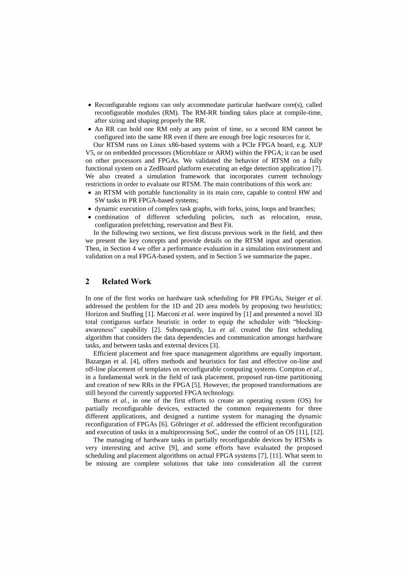
Figure 3 shows the task graph that the RTSM will manage. In this Figure we express
the HW/SW execution times and reconfiguration time in arbitrary time units in order to
make the understanding easier. The task graph has one instance in which three tasks
have more than one dependency, i.e. T3, T7 and T8, which results in join operations.
Also, in T2 there are fork operations. The available resources consist of two RRs and
one SW-PE, as well as the FPGA configuration port, which is also treated as a resource
to be scheduled. Also, the RTSM accepts as input the width and height of each RR;
these are used by the Best Fit in Space function.
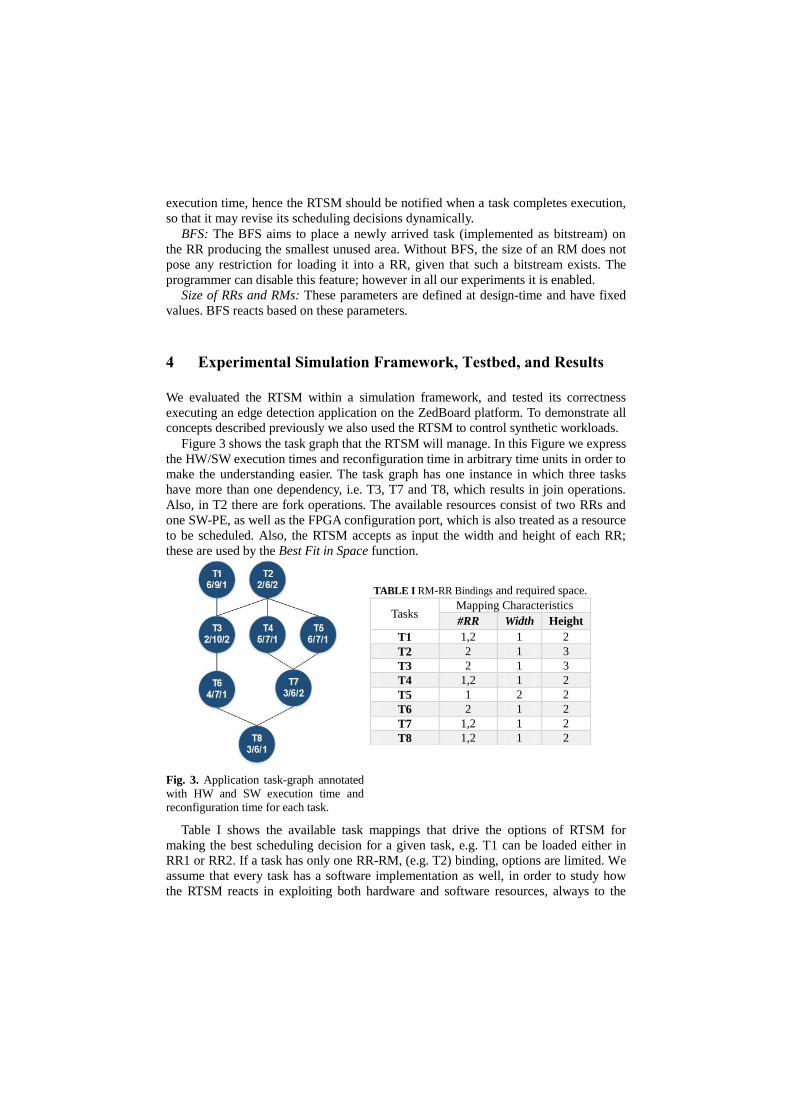
TABLE I RM-RR Bindings and required space.
Fig. 3. Application task-graph annotated
with HW and SW execution time and
reconfiguration time for each task.
Table I shows the available task mappings that drive the options of RTSM for
making the best scheduling decision for a given task, e.g. T1 can be loaded either in
RR1 or RR2. If a task has only one RR-RM, (e.g. T2) binding, options are limited. We
assume that every task has a software implementation as well, in order to study how
the RTSM reacts in exploiting both hardware and software resources, always to the
Tasks Mapping Characteristics
#RR Width Height
T1 1,2 1 2
T2 2 1 3
T3 2 1 3
T4 1,2 1 2
T5 1 2 2
T6 2 1 2
T7 1,2 1 2
T8 1,2 1 2
advantage of the overall application execution time. It is important to note that the
software implementation of a task has a longer execution time than the hardware one.
The scheduling result of the experiment presented is shown in Figure 4. In this
execution most of the RTSM features were activated. Relocation is activated to
accommodate task T2. Since Best Fit in Space (BFS) function has placed task T1 on
RR2, in order to place task T2 on the FPGA, the RTSM first performs relocation and
reconfiguration of task T1 on RR1, and then reconfigures T2 to the now empty RR2.
Additionally, the decision to execute task T5 on SW-PE is due to the Best Fit in Time
(BFT) function as a later reservation of task T5 on a RR gave a longer completion time.
Fig. 4. The scheduling outcome of our example, showing features such as relocation, reservation
and prefetching. The use of the SW version of task T5 completes faster the overall execution.
Also we can see the use of Reservation on the decision taken for task T3. The
arrival time of task T3 is on t=10 and since the only available bitstream binds task T3
to RR2, there is no other option but to reserve task T3 for later execution on RR2. Note
that the scheduler does not relocate task T4 to RR1, because T4 is near completion of
its execution (otherwise it would restart its execution).
Finally, there is a high level of inner task parallelism between tasks of the same
level but also from different levels, i.e. tasks T1, T2, T4, and T5, and we observe the
use of configuration prefetching for tasks T7 and T8.
4.2 Discussion
In the example above we observe the following:
The task graph is complex enough to demonstrate fork and join operations. We
assumed multiple bitstreams per task to show the flexibility of RTSM.
We demonstrated almost all RTSM features: relocation, reservation, prefetching,
BFT and BFS. The reuse policy was not demonstrated as no task is repeated, nor
does the task graph contain a loop. We also did not demonstrate the use of JHM, as
we did not assume availability of such bitstreams.
In Figure 4, we obtain that relocation takes place from the very beginning of the
scheduling. This evidences that our approach is dynamic, i.e. at each point of time
the RTSM reacts according to the FPGA condition and task status.
We assumed that the SW-PE execution takes more time than the combined
hardware execution and reconfiguration operation, prompting the scheduler to
choose the hardware accelerator to program in the FPGA.
Finally, we assumed that HW task execution time is 2-3 times larger than the
reconfiguration time, to model fast reconfiguration times or coarser grain tasks.
4.3 Validating the RTSM with a Real-World Application
We validated the behavior of RTSM on a fully functional system on a ZedBoard
platform executing an edge detection application [7]. Figure 5 shows the system
architecture that features two ARM Cortex-A9 cores, two reconfigurable regions acting
as the HW-PEs each of which is connected to a DMA engine, and a DDR3 memory.
We used CPU0 for the RTSM and CPU1 as the SW-PE, executing SW tasks.
Fig. 5. System architecture of the Zynq platform.
At system start-up, the system is initialized by the on-board flash memory; the boot
loader initializes CPU0 with the RTSM code, sets-up CPU1 as the Processing Element
(PE), and loads the initial bitstream in the programmable logic. Then the RTSM loads
the application description (task graph, task information, task mappings, etc.) from the
SD card. It also transfers the partial bitstreams from the SD to the main (DDR3)
memory. During normal operation the RTSM takes scheduling decisions and issues
tasks, on the SW-PE, i.e. CPU1, and the two HW-PE, i.e. RR1 and RR2.
The edge detection application consists mainly of four filter kernels executing in a
sequence: Gray Scale, Gaussian Blur, Edge Detection and Threshold [7]. For these
tasks, we have both a HW version as partial bitstreams, and a SW version; the RTSM
will decide which version (SW or HW) is better to use based on the run-time
availability of HW- and SW-PEs. The input image is loaded from the SD card, while
intermediate images resulting after processing each task and the final output image are
also written back to SD card. The transfer from and to the SD card is performed by SW
tasks running on CPU1, which also controls partial reconfiguration of HW tasks.
Figure 6 depicts the task graph of the application, showing only task dependencies but
not how the application will execute over time. We also include the (implicit) SW tasks
that perform the reconfiguration process.
The CPUs communicate with each other through the on-chip shared memory using
two memory locations, one for each communication direction, using a simple
handshake protocol (set and acknowledge/clear). One flag shows the PE status where a
“-1” indicates that the PE is idle and the RTSM can issue any SW task to it; when the
PE is busy, the flag indicates the task assigned, e.g. “2” for SW_imageRead, “3” for
SW_imageWrite, etc. Once the PE completes the task execution, it informs the RTSM
using the other flag indicating the type of the completed task.
In the system architecture of Figure 5, the two RRs are connected to the processing
ARM cores through an AXI_Lite bus running at 75MHz, and through a DMA engine,
each one having read and write channels on a dedicated AXI_Stream running at 150
MHz. The AXI_Stream is connected to the processor High Performance ports that
provide access to DDR memory. To execute a HW task, the RTSM issues a
reconfiguration command to CPU1, which in turn configures the FPGA with the
corresponding bitstream through the PCAP configuration port. Once partial
reconfiguration completes, RTSM initiates the HW task execution, programs the
appropriate values and triggers the corresponding DMA engines and kernel filters. All
HW mappings of the kernels were implemented with the Xilinx HLS tool that also
creates automatically the SW drivers for the SW/HW communication over the
AXI_Lite bus. When a kernel completes execution, it generates an interrupt to the
RTSM, which then updates its structures and proceeds to a new scheduling decision.
Fig. 6. Edge Detection Application Task Graph.
The RTSM operation can be broken down into different phases shown in Table II.
The Table also lists the total time spent on an ARM A9 Cortex CPU for each distinct
phase, both in clock cycles and μs. The RTSM initialization phase is performed only
once and it includes fetching from the flash memory the initialization file that
describes the tasks the control flow graph and the task mappings, parsing it, and
initializing the RTSM data structures. In the RTSM initialization time we do not
include the overheads for loading the file from flash memory and for transferring the
partial bitstreams to DDR3 memory. The Schedule phase refers to the time needed to
execute the Schedule function in order to take a decision about the task to be executed
next, i.e. when and where this task is going to be executed. The Issue Execution phase
refers to the time required to issue either a reconfiguration or execution task
instruction, depending on what the scheduling decision was. Also, depending on
whether a HW core is reused, the RTSM checks if configuration prefetching can be
performed. The HW Task completion phase & SW Task completion phase refer to
updating the RTSM data structures after the completion of a HW or SW task, and to
resolving the dependencies in order to set the next task in the graph as “arrived”.
Finally, the Reconfiguration task completion & HW task execution issue phase refer to
the interval in which the RTSM receives a reconfiguration completion notification
from the PE, issues a task execution command, and checks whether it can perform
configuration prefetching of a not yet “arrived” task.
The overall execution time of the application was measured to be 129.62 ms, while
the total RTSM overhead derived from Table 2 is 0.112 ms. The theoretical
reconfiguration overhead, given that PCAP has a throughput of 400MB/sec, is 0.6 ms.
This is added only once, since in the rest cases of our example configuration
prefetching takes place and hides the reconfiguration overhead with HW execution.
However, since we use a SW task to perform reconfiguration, the throughput is
considerably lower at 50MB/sec, increasing the reconfiguration cost to 5ms. Still,
compared to the total execution time of application, this overhead is negligible.
TABLE II. Time per each distinct phase of the RTSM, running on ARM A9 at 667MHz.
RTSM phases #Clock Cycles Elapsed time (μs)
RTSM Initialization 7,707 23.121
Schedule 17,346 52.038
Issue Execution 5,995 17.985
HW Task completion 2,493 7.479
Reconfiguration task completion &
Hardware task execution issue 1,224 3.672
SW Task completion 2,748 8.244
Finally, we compare the performance of our system with the one presented in [7].
That work used the same application running on a Xilinx Virtex-5 FPGA and reported
a throughput of 18 fps for a 640x480 image. In our case, we used a 1920x1080 image,
and we measured a throughput of 7 fps. By converting the two results into pixels per
second throughput, our system is faster by a factor of 2.6. Since the two platforms are
quite different, a direct comparison is not easy; for example in the Zynq we use the
ARM hard processors while the V5 supports only soft-core MicroBlaze processors.
Regarding portability, our initial RTSM was developed on an x86 ISA desktop;
porting it to the ARM architecture required only (i) cross-compiling the code, and (ii)
the re-implementation of architecture specific drivers and communication protocols
between the RTSM and the Processing Elements.
5 Conclusions
We presented a run-time system to efficiently schedule HW and SW tasks in systems
with partially reconfigurable FPGAs. We plan to develop complex use-cases, e.g. task
graphs with branches and loops that will allow for demonstrating and evaluating all the
features of RTSM on actual FPGA platforms. One obstacle to this effort (by us and
other researchers) is the lack of standard interface across different applications, and
designers have to manually intervene to adjust the RTSM and the task application
interfaces, according to the specifics of each platform. Our RTSM relieves the designer
from the task invocation complexities; he/she only has to address the task data
interface with the core part of the RTSM..
Acknowledgment. This work was supported by the European Commission FP7
FASTER project (#287804) and the HiPEAC Network of Excellence (#287759). We
also thank Marco Santambrogio and NECST Lab from the Politecnico di Milano for
providing the initial image processing (Edge Detection) application.
References
1. C. Steiger, H. Walder, and M. Platzner (2004): “Operating Systems for Reconfigurable
Embedded Platforms: Online Scheduling of RealTime Tasks”. In: IEEE Transactions on computers, Vol. 53, No. 11.
2. T. Marconi, Y. Lu, K.L.M. Bertels, G. N. Gaydadjiev (2010): “3D Compaction: a Novel
Blocking-aware Algorithm for Online Hardware Task Scheduling and Placement on 2D
Partially Reconfigurable Devices”. In: Proc. of the International Symposium on Applied Reconfigurable Computing (ARC), pp. 194-206, Bangkok, Thailand.
3. Y. Lu, T. Marconi, K.L.M. Bertels, G. N. Gaydadjiev (2010): “A Communication Aware
Online Task Scheduling Algorithm for FPGA-based Partially Reconfigurable Systems”. In Proc. of the IEEE Symposium on Field-Programmable Custom Computing Machines.
4. K. Bazargan, R. Kastner, and M. Sarrafzadeh (2000): “Fast Template Placement for
Reconfigurable Computing Systems”. In: IEEE Design and Test of Computers, vol. 17, no. 1, pp. 68-83.
5. K. Compton, Z. Li, J. Cooley, S. Knol, S. Hauck (2002): “Configuration Relocation and
Defragmentation for Run-Time Reconfigurable Systems”. In: IEEE Trans. on VLSI, Vol.10,
No.3.
6. J. Burns, A. Donlin, J. Hogg, S. Singh, M. de Wit (1997): “A Dynamic Reconfiguration
Run-Time System”. In: Proc. of the 5th Annual IEEE Symposium on Field-Programmable Custom Computing Machines.
7. G. Durelli, C. Pilato, A. Cazzaniga, D. Sciuto and M. D. Santambrogio (2012): “Automatic
Run-Time Manager Generation for Reconfigurable MPSoC Architectures”. In: 7th
International Workshop on Reconfigurable Communication-centric Systems-onChip (ReCoSoC).
8. P. Lysaght, B. Blodget, J. Mason, J. Young, B. Bridgford: “Invited Paper: Enhanced
Architectures, Design Methodologies and CAD Tools for Dynamic Reconfiguration of
Xilinx FPGAs”. In Proc. FPL 2006: 1-6
9. L. Bauer, A. Grudnitsky, M. Shafique, and J. Henkel, “PATS: A Performance Aware Task
Scheduler for Runtime Reconfigurable Processors”, in Proc. of IEEE Symposium on Field-Programmable Custom Computing Machines (FCCM) 2012.
10.A. Morales-Villanueva and A. Gordon-Ross, “On-chip Context Save and Restore of
Hardware Tasks on Partially Reconfigurable FPGAs”, in Proc. of IEEE Symposium on Field-Programmable Custom Computing Machines (FCCM) 2013
11.D. Göhringer, M. Hübner, E. Nguepi Zeutebouo, J. Becker: “Operating System for Runtime Reconfigurable Multiprocessor Systems”. Int. J. Reconfig. Comp. 2011 (2011)
12.D. Göhringer, S. Werner, M. Hübner, J. Becker: “RAMPSoCVM: Runtime Support and Hardware Virtualization for a Runtime Adaptive MPSoC”. In Proc. FPL 2011: 181-184
13.C. Conger, A. Gordon-Ross, A. D. George: “Design Framework for Partial Run-Time FPGA Reconfiguration”. ERSA 2008: 122-128
14.Z. Li, S. Hauck: “Configuration prefetching techniques for partial reconfigurable coprocessor with relocation and defragmentation”. FPGA 2002: 187-195
15.Vipin, Fahmy, “Architecture-Aware Reconfiguration-Centric Floorplanning for Partial Reconfiguration”, in Proc. ARC 2012.