AbstractThe automotive industry experiences a major change as vehicles are gradually becoming a part of the Internet. Security concepts based on the closed-world assumption cannot be deployed anymore due to a constantly changing adversary model. Automotive Ethernet as future in-vehicle network and a new E/E Architecture have different security requirements than Ethernet known from traditional IT and legacy systems. In order to achieve a high level of security, a new multi-layer approach in the vehicle which responds to special automotive requirements has to be introduced. One essential layer of this holistic security concept is to restrict non-authorized access by the deployment of embedded firewalls.
This paper addresses the introduction of automotive firewalls into the next-generation domain architecture with a focus on partitioning of its features in hardware and software. Based on the deployment of the firewall in the in-vehicle network, the corresponding adversary model and automotive requirements such as latency, jitter, CPU load and memory consumption are going to be discussed. Drivers behind these metrics are primarily safety concerns and cost and thus are relevant for both OEMs and hardware manufacturers. As a result, a reasonable implementation of an automotive firewall system has to be a trade-off between hardware and software in order to meet the above-named automotive requirements. We implemented the firewall on an Infineon AURIX TriCore and Altera Cyclone V FPGA to analyze these metrics. The paper shows the options and decision points to find an optimal partitioning between hardware and software for an automotive embedded firewall system.
IntroductionAutomotive Ethernet is gradually making its way to be used as a communication backbone and is expected to be deployed in vehicles as soon as 2018 [1]. The introduction of this communication protocol comes along with some serious changes in the required security
concept in order to respond to changing parameters such as bandwidth as well as rising cybersecurity concerns in the automotive domain.
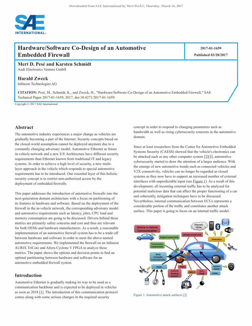
Since at least researchers from the Center for Automotive Embedded Systems Security (CAESS) showed that the vehicle's electronics can be attacked such as any other computer system [2][3], automotive cybersecurity started to draw the attention of a larger audience. With the emerge of new automotive trends such as connected vehicles and V2X connectivity, vehicles can no longer be regarded as closed systems as they now have to support an increased number of external interfaces with unpredictable input (see Figure 1). As a result of this development, all incoming external traffic has to be analyzed for potential malicious data that can affect the proper functioning of a car and coherently, mitigation techniques have to be discussed. Nevertheless, internal communication between ECUs represents a considerable portion of the traffic and constitutes another attack surface. This paper is going to focus on an internal traffic model.
Figure 1. Automotive attack surfaces [3]
Hardware/Software Co-Design of an Automotive Embedded Firewall
2017-01-1659
Published 03/28/2017
Mert D. Pesé and Karsten SchmidtAudi Electronics Venture GmbH
Harald ZweckInfineon Technologies AG
CITATION: Pesé, M., Schmidt, K., and Zweck, H., "Hardware/Software Co-Design of an Automotive Embedded Firewall," SAE Technical Paper 2017-01-1659, 2017, doi:10.4271/2017-01-1659.
A holistic security concept based on a multi-layer approach in the car has to be considered for a high level of security in cars which has to respond to a changing adversary model. [4] suggests four levels of security barriers:
• Access control to network • Secure on-board communication • Data usage policies • Anomaly detection and defense
The first level elaborates on restricting non-authorized access to the in-vehicle network (IVN) by the means of filters/firewalls. The second level suggests ways for message authentication and ensuring data integrity. Furthermore, semantics have to be analyzed and policies restricting the execution of critical functions have to be defined. This is already partly achieved through firewalling. Last but not least, anomalies have to be detected and mitigated by the means of Intrusion Detection and Prevention Systems (IDPS) which are constantly checking several properties of network traffic and reacting to deviations.
This paper focuses on the first level of this concept and addresses an automotive firewall concept and design. We will especially concentrate on how an optimal partitioning of firewall features based on automotive requirements can be achieved. Please note that this proof-of-concept just constitutes one possible approach for an automotive firewall design and not a final solution. First, we will give a quick overview of existing firewall technologies and discuss the adversary model as well as special automotive requirements. Related work on HW/SW co-design of firewalls will also be introduced. In the next chapter, we will present a concept and experimental setup for the implementation of an automotive firewall in HW and SW. Eventually, this test system is evaluated and recommendations for an optimal partitioning between hardware and software are given.
Problem Statement and Related Work
Basic ConceptsThis chapter will introduce basic concepts for the understanding of this paper, such as a vehicle’s E/E architecture, available firewall technologies and the corresponding adversary model to identify possible attacks on a firewall.
In the upcoming domain controller architecture, a decentralized approach is going to be pursued in the automotive E/E architecture. Domains will not merge into a centralized gateway anymore, but will be connected to special ECUs called domain controllers (DCs). Ethernet will be used as a backbone to connect multiple domain controllers with a connectivity gateway, as depicted in Figure 2. As a result, Ethernet will be a shared medium responsible for transporting all internal communication between the DCs as well as external traffic from outside the gateway (e.g. LTE, OBD) to the respective ECUs in a domain.
For the design of the firewall, the domain architecture is going to be considered as the firewall will be based on Ethernet. Domain controllers are directly connected to the switch of a connected gateway using Ethernet. The data rate of the link between a domain controller and the switch can vary according to the required
bandwidth. For instance, the transmission rate of the link between the powertrain domain controller and the gateway is usually 100 MBit/s as only small control messages are sent whereas the link between the infotainment unit and gateway might need Gigabit connection to satisfy the excessive bandwidth of multimedia data. In our example, the gateway is also connected to the outside by two external interfaces. For these again, Ethernet is used in different speed grades. One interface is for diagnostic purposes and the other is a cellular module for remote wireless connections via LTE, WiFi, etc.
The domains from Figure 2 can be grouped into different security zones. These are an approach to separate large topologies such as the vehicular on-board network into small virtual networks. This can be achieved through the use of VLANs. To sum up, VLANs enforce the separation of domains which is important as e.g. ECUs in the powertrain domain shall not communicate with ECUs in the infotainment domain and vice versa. Basically, they make communication only possible between nodes in the same VLAN.
Figure 2. Future domain controller architecture with indicated security zones
The major firewall technologies can be summarized as stateless packet filters, stateful packet inspection, proxy servers and application layer firewalls with capabilities of deep packet inspection. The latter one additionally analyzes layers 5-7 in the OSI model whereas the rest just supports up to layer 4. Simple packet filters just analyze the header fields of the protocols on layer 2-4, such as MAC addresses, IP addresses and port numbers. They do not store any information about the state of a connection and thus have to apply the entire filter to every incoming packet. In terms of the adversary model, this type of firewall is able to block unauthorized traffic and possible malicious data from reaching its destination. [6] categorizes attacks in a domain controller architecture into obtaining network control by installing or corrupting a device on the network to control the operation of other devices, denial of service (DoS) attacks in order to deny access to network resources to other devices on the network and snooping or information theft. According to classification, stateless packet filters can only prevent network control. Stateful packet filters have the additional capability of tracking a connection’s state by working with a state table. In the case of TCP, incoming packets would be analyzed for their flags in the TCP header and this information would be used to identify that packet as part of an existing or the beginning of a new connection. This firewall type does not only reduce the time needed for the packet to pass through the firewall but also can detect some DoS attacks such as SYN flooding. As a result, integrity and availability can be ensured by firewalls whereas confidentiality in terms of snooping the content of traffic on the network has to be handled by other layers in the multi-layer approach. More advanced firewalls also support features such as rate limiting, probability-based matching or unicast reverse path forwarding (URPF) verification. Application layer firewalls are stateful packet filters also supporting several protocols on the top layers and are often – in combination with deep packet
inspection – very effective as not only the packet headers, but also the payload is analyzed. Unfortunately, the more sophisticated a firewall gets, it comes at the expense of performance, leading to the problem of finding a sufficient trade-off between functionality and performance.
Automotive RequirementsTypical requirements for firewalls in IT are throughput and latency caused by the processing of the firewall. These requirements are certainly also important for the evaluation of a firewall performance in vehicles, but not sufficient as Automotive Ethernet has different drivers.
Security is an abstract term that describes the hardiness of a system against deliberate attacks. Security consists of the following properties: safety, dependability, availability, maintainability, integrity and confidentiality. For automotive security, safety and dependability are key properties. The vehicle has to operate properly without failing for a certain amount of time. Otherwise, safety cannot be guaranteed and can result in abysmal consequences for passengers and their environment.
Without any doubt, functional safety is the primary driver which leads to a redefinition of requirements in an automotive firewall design. Compared to IT, safety requirements are considerably higher and adherence to time limits is essential. E2E latency and particularly jitter are decisive metrics in the design of a firewall since internal communication has fixed timing deadlines which might not be exceeded. For instance, we can assume that certain control signals have to reach their destination in under one millisecond to maintain proper functionality of the vehicle’s functions. [7] even acts on the assumption that a control signal transported over UDP has to meet a deadline of just 100µs. As we will see later, these hard real-time requirements are difficult to satisfy with a pure SW implementation.
Another driver defining new requirements in the automotive is cost which is interesting for both OEMs and semiconductor manufacturers. Cost is heavily affected by the used hardware. As a result, RAM usage and CPU load have to be considered in the firewall design. Automotive hardware usually features custom-made chips which are manufactured in high quantities. A more optimized usage of the memory or load on the CPU would result in cheaper prices of a single IC and thus both OEM and chip manufacturer would benefit from an optimized firewall design. Furthermore, cost is not the only driver for aiming at a minimum CPU load. As we will discuss in the next chapter, software firewalls are intended to be deployed on DCs. These ECUs have several other tasks running on them as the entire domain traffic is running together at it. In order to ensure higher priority safety-critical tasks enough resources to function properly, the firewall task has to claim the CPU as little as possible.
Throughput is another relevant metric in a firewall design, especially in IT. Firewalls reduce the throughput as a result of the additional processing pipeline the packets have to traverse before reaching their destination. Depending on the location of the firewall in the IVN, this can be a real problem at choke points. In the E/E architecture of the car, the connectivity gateway could be such a choke point since multiple domain controllers which at least require a 100Mbit/s link to
the gateway need the gateway to work properly with data rates of up to 10Gbit/s (considering 10 DCs and 5 1Gbit/s and 100Mbit/s DCs respectively). Thus, we need to analyze the impact of a firewall design on the throughput of Ethernet traffic.
Eventually, some further automotive only requirements are going to be mentioned, but not analyzed later in the test setup. A major difference between firewalls in IT and vehicles is the configurability. After production time, it is harder to update rule sets than in a locally administered computer network. This point gets more important when a mandatory long life cycle of ECUs and thus the firewall application is taken into consideration.
Related WorkBefore continuing with the firewall concept we are going to suggest for vehicles, a brief summary on related work on HW/SW partitioning of firewalls shall be given.
[9] suggests a hybrid packet filter based on netfilter/iptables [10] on the software side and an FPGA implementation as the hardware solution. Theoretically, hardware can range from GPUs over NPUs to FPGAs. The basic idea was to keep the simple part of the packet filtering in specialized matching hardware and the complex part with more sophisticated rules in software. The hardware rules shall be kept general so a lot of pre-processing can already be done at hardware level which comes with considerably lower network latency [11]. Furthermore, according to [8], examinations of real-world traffic showed that the major part of traffic can already be analyzed with simple packet filter rules and this can be a significant performance boost. More difficult rules which are getting updated over time (e.g. by OTA) are kept in software for easier configurability.
Search operations in software are sequential and the simplest, but also slowest form is linear search as it is used in netfilter. Linear search consumes less memory resources though and are thus ideal for the SW firewall implementation in our case. Searching in hardware is more effective, as it can be parallelized by processing the incoming packet by parallel filter blocks, each implementing a rule of the policy. The most common architecture for this is Content Addressable Memory (CAM) as it can search input data in a fixed number of clock cycles. CAM is a widely used technology and commonly implemented in Ethernet switches.
System ConceptThis chapter describes our firewall design which is going to be evaluated based on the most relevant automotive requirements.
Our experimental setup is depicted in Figure 3. It consists of two state-of-the-art multicore automotive grade MCUs. We deployed AURIX™ TriCore™ TC297-TF [17] boards from Infineon which act as a DC in our IVN. The reason for choosing this MCU is its wide use as automotive ECU as well as offering a 100Mbit/s Ethernet interface. The MCUs are running ERIKA Enterprise, an open-source and real-time OSEK/VDX compliant kernel which is widely used real-time OS for automotive ECUs. We deployed lwIP [12] as TCP/IP stack on the OS as it has a relatively small footprint compared to other competitors. For the hardware implementation, we chose an Altera Cyclone V FPGA [14] with two Fast Ethernet ports (without
taking advantage of its HPS capabilities). In the setup, we used an attacker MCU and a victim MCU which are connected by a Layer-2 switch. The FPGA is connected between the switch and the victim MCU as a packet filter and preprocesses the incoming traffic from the attacker. For time measurements, we used the Precision Time Protocol (PTP). This protocol can synchronize clocks on network nodes with up to 1µs accuracy so all devices have the same reference time. For this purpose, an open-source implementation of PTP called PTPd has been implemented on the MCUs and it provides a hardware accuracy of 25µs. In order to enhance the time precision, we used a PTP-capable network switch in our setup.
Figure 3. Experimental Setup
In the following, we are going to focus on internal firewalls only. Although external firewalls are also of utmost importance [5], the adversary model for this kind of communication is completely different than for internal communication. The main threat in internal communication is the compromise of an ECU or a DC in the IVN which sends unauthorized data to other domains and thus possibly affecting the functionality of the vehicle. Another notable attack category are DoS attacks to make other ECUs go offline which has severe consequences for passenger safety.
The setup in Figure 3 tries to imitate a real-world E/E architecture. The MCUs represent DCs and the switch is part of the connectivity gateway connecting all DCs of the Ethernet backbone as depicted in Figure 2. The FPGA in the setup imitates a firewall located on top of the switch inside the gateway. Thus, in a real-world setup it would sit at the choke point of the entire internal Ethernet traffic and have to handle high throughputs. Furthermore, the gateway would have additional external firewalls shielding external interfaces such as the LTE module which are not considered in our setup. To sum up, the domain controller architecture will have multiple distributed firewalls which are specialized for different traffic conditions.
The HW firewall on the FPGA is a simple packet filter which takes the Ethernet packets from the attacker as an input and immediately drops packets which are not allowed on the internal network according to a pre-defined whitelist policy. Only packets matching one of the rules in this rule set are allowed to be shunted to the DC which runs a SW firewall for further classification. The SW firewall is a stateful packet filter which analyzes packets that passed the first firewall on the FPGA. It has a more sophisticated logic as it can analyze the connection state of TCP packets and detect DoS attacks such as SYN flooding. Furthermore, it features rate limiting to slacken off incoming traffic to the MCU in order to preserve its CPU load.
For analyzing the impact of each firewall functionality, the SW firewall is built modularly as depicted in Figure 4. We will see why parts of the packet filtering should already be done at an early stage by the FPGA and what functionalities should be kept on the MCU. As a result, this paper will give recommendations for an optimal partitioning of firewall functionalities in HW and SW based on metrics such as E2E latency, jitter, throughput, memory consumption and CPU load.
Figure 4. Successive analysis of firewall functionalities on MCU
EvaluationThe following diagrams refer mostly to measurements on the victim MCU if not indicated otherwise. The reasons behind this is that the impact of the co-design can either only be evaluated on the victim MCU (E2E latency, jitter) or it cannot be measured on the FPGA (CPU utilization).
E2E Latency and JitterThis section analyzes two of the most important metrics, latency and jitter. First of all, we want to explain the workflow on the MCUs without the FPGA included in the setup. On both DCs, client/server parts of TCP or UDP sockets were running using the Socket API of lwIP. For measuring the time difference between attacker and victim, we used the PTPd implementation as already mentioned. The attacker put its PTP synchronized timestamp into the payload of the TCP segment or UDP datagram right before sending it. After reception of the packet on the victim side, this timestamp was extracted and the difference to the current time on that MCU was calculated in the Socket API task. As a result, the E2E latency we are referring to here includes delays caused by the TCP/IP stack it has to traverse before it arrives at the high level socket task. We are only interested in the additional delay caused by the firewall application so the stack delay can be neglected. The firewall task is embedded into the receive path of the TCP/IP stack. Shortly after the Ethernet frame has been made available by the MAC, it is being classified according to its delivery semantic (Unicast, Multicast, Broadcast) and its header fields are being extracted from the packet. Based on the number of filter rules defined during initialization of the firewall, it is matched against each of them until a match is found. In the case of a match, the packet is given permission to continue its route in the receive path (i.e. it is passed to the Layer 3 handler, etc.). If no rule matches the packet, it is discarded and is not further processed by the TCP/IP stack. We want to point out that all filter rules are stored efficiently in the RAM of the MCU and are matched sequentially against the input data.
For the FPGA implementation, we chose an open-source Layer 2 switch IP core [15] as a base line for our packet filter implementation. Due to hardware restrictions of the board, the interfaces could only support MII interfaces of up to 100Mbit/s. The FPGA application uses a clock rate of 150MHz for data operations, 100MHz for search operations and 50MHz for various control tasks. We want to point out that the MAC used in our IP core does not support PTP and thus incoming and outgoing frames through this HW switch are not synchronized. Again, this was not an issue for the preciseness of our timing calculations since the delay through the FPGA (i.e. reading, filtering, switching, shunting) was constant for packets of the same length. The reason for a constant delay of just 2 clock cycles for packet filtering is described in Figure 5. As already mentioned, the extracted relevant header data is used as an input to multiple parallel match units. They receive the input at the same time and match the input against one filter rule each in just one clock cycle. The results of the match units are then combined to a match vector and a decision is made. Using the search clock of 100MHz for the match units, the packet filtering operation can be finished in just 20ns. Combined with the reading, writing and switching delay, the FPGA takes a maximum of 79µs for a packet with an MTU length of 1500 bytes which is very high. Although the switch delay is relatively small compared to that value (few microseconds), reading the data from the input PHY and writing it to the output PHY takes a considerable amount of time. Simulated with RGMII instead of MII, the maximum time for a packet of the before mentioned MTU reduces to 28µs. Compared to 700µs E2E latency of a packet with MTU length (not depicted in any figures in this paper), this is a relatively small amount which can be taken into account if further advantages of FPGA packet filters prevail. As a result, an FPGA with at least Gigabit Ethernet ports is required for our combined firewall to work properly. The actual firewall delay can be defined as the time between the last byte of the packet is received and the first byte of the processed packet is transmitted. This figure currently stands at approximately 3µs. The switch delay is not included in this time since the switching is already done while the packet is being received. Furthermore, please note that CAM is not going to be used in our firewall design as it does not meet automotive requirements: They are expensive in memory resources and power-intensive. Instead, an alternative matching unit (see Figure 5) is deployed.
We provide a fully configurable firewall test setup on an MCU and an FPGA. The amount of filter rules can be set on both devices. Furthermore, the MCU offers more parameters such as the size of the TCP state table, the rate limit and several more which can all be configured freely by the user.
Figure 5. Parallel processing of header data in match units
For our evaluation, we are using a rule set of 16 filter rules, a TCP state table size of 16 entries and a rate limit of 10 packets per second. For each measurement, packets were captured for 60 seconds so enough data points were available for a reasonable evaluation. Scenarios for SYN flooding which can be detected by the MCU or a full benchmark are not depicted in the following. Our goal is to convey the relevant impacts of single firewall functions in HW and SW on the E2E latency and jitter and to implicate decision points for the partitioning of firewalls in HW and SW.
The following two diagrams in Figure 6 and 7 focus on the E2E latency of a simple packet filter implementation on the victim MCU. It can easily be seen that the latency increases linearly with the number of filter rules. The first data point indicates that no packet filter is activated. If you consider a possible definition of 500 rules in a firewall ruleset, the resulting E2E latency can be approximated to 2.3ms (TCP and UDP). A firewall delay of approximately 2.2ms would not meet the deadlines for certain signals as specified in [7]. This is also the reason why a standalone SW packet filter is not suited for automotive firewall applications.
Figure 6. E2E latency Packet Filter for TCP traffic as a function of number of filter rules
Figure 7. E2E latency Packet Filter for UDP traffic as a function of number of filter rules
The jitter is at least as important as the average delay caused by the packet filter. The deviation from the mean value for each measurement is depicted in the boxplots in Figures 6 and 7. The maximum difference between a data point and the mean value is called jitter or Instantaneous Packet Delay Variation (IPDV) as defined in RFC 3393 [13]. This metric is displayed in Figure 8 for packet filters. Apart from some spikes at the UDP curve, we can say that the IPDV is constantly below 40µs for TCP and 20µs for UDP. These values have to be considered in our analysis as they describe the worst case for E2E latency.
Figure 8. Jitter as a function of number of filter rules for TCP and UDP traffic
Figure 9. E2E latency for different modules for TCP traffic as a function of number of filter rules
So far, we only analyzed the timing of packet filters. In our firewall design, we also want to analyze the impact of rate limiting and stateful packet inspection on E2E latency and jitter. Figure 9 compares the E2E latency mean for all three functionalities. Rate limiting is just an additional module before the matching algorithm starts to classify the packet. The MCU uses an internal timer to measure the amount of packets in a time span and compares this calculated value to a user-defined parameter. All traffic is dropped at reception time if the packet rate is higher than the desired value. As can be seen from Figure 9, rate limiting barely affects the E2E latency for a larger number of filter rules. The addition of stateful packet inspection leads to a major enhancement in latency as it remains constant independent of the number of filter rules. A TCP packet initially traverses the filter ruleset just once and is added to the
TCP state table. After the entry has been added, packets belonging to this connection are identified and matched against the entries in the state table which only stores the tuple of IP addresses and port numbers. We considered an empty state table for the measurement in Figure 9. The SIF module furthermore has the capability to delete closed connections during runtime in order to prevent a buffer overflow. The jitter for these two additional modules is not shown, but remains approximately the same as in the packet filter scenario.
To sum up, RL and SIF are functionalities which do not affect E2E latency negatively. Latency of a stateless packet filter scales poorly with a larger amount of filter rules. The jitter remains constant among all three variations. Although a SW implementation with enabled SIF keeps the latency relatively low and constant, it can still be enhanced by using a HW packet filter as even with SIF, the first packet of a connection has to be checked against all the rules (and in the worst case it can take pretty long). Other reasons for using a combined HW/SW solution will be given during discussion of the following metrics.
ThroughputThe throughput is defined as the ratio of the amount of data that is transferred between two points in a certain time. For analyzing the throughput, it makes sense to analyze it for different packet payload lengths. Figure 10 shows the throughput for a packet filter with RL functionality for UDP traffic. Without any enabled firewall, the throughput for the MSS of UDP is approximately 20.8 Mbit/s. This value decreases with an increasing number of filter rules as the E2E latency increases. A stateful packet filter would lead to constant throughput as the latency remains constant as well. Again, by a HW packet filter implementation instead of on SW, we would not negatively affect the throughput in our network.
Figure 10. Throughput for UDP traffic with rate limiting as a function of number of filter rules and packet length
Memory ConsumptionMemory consumption refers to FLASH and RAM usage of the MCU. Especially RAM is a valuable resource which usually has a smaller size than FLASH, primarily due to higher production costs. In the following, we are going to present the total memory consumption of the firewall on the MCU as a function of the number of filter rules and firewall functionalities. Furthermore, we will separately analyze the RAM usage. Figure 11 depicts the total memory consumption (FLASH and RAM) whereas Figure 12 only shows the more
important RAM usage. In both cases, the memory increases linearly with the amount of filter rules. We assumed 16 state table entries for the SIF case. The figures show that the RAM consumption makes up approximately a fifth of the entire memory usage.
Figure 11. Total memory size as a function of number of filter rules and firewall functionalities
The automotive multi-core MCU used in our experiments features 768 kB of RAM [17] which is relatively high compared to other automotive MCUs [16]. Assuming a full firewall application running on the MCU with 500 filter rules, rate limiting. stateful packet inspection and considering a linear increase of RAM according to Figure 12, the used RAM size will add up to 107 kB resulting in an additional RAM size of 33 kB solely for the firewall application. As a result, the firewall scales poorly for a more complex filter ruleset, but only requires an additional constant RAM size of approximately 1 kB for stateful inspection (size of state table). In a combined setup of FPGA and MCU with the MCU merely running the SIF module, the memory advantage is obvious.
Figure 12. RAM usage as a function of number of filter rules and firewall functionalities
To sum up, the main source of memory consumption is the packet filter module. It is recommended to save valuable RAM size on the MCU by implementing the packet filter on the FPGA. Besides better E2E performance, the FPGA offers a resource conserving memory utilization as well. The resource utilization of the FPGA (Altera Cyclone V 5CSXFC6D6F31C8) is displayed in Table 1. Since we did
not use CAM blocks in our design (they are built from RAM modules), the total amount of block memory bits remains constant. A CAM block consisting of just 16 rules would consume an additional 6% of the block memory. If we consider 500 filter rules again, the logic utilization will increase to 35% of the available ALMs for our device.
Table 1. FPGA Resource Utilization for Ethernet dual-port switch application without and with packet filter (16 filter rules)
CPU LoadLast but not least the CPU utilization on the MCU is going to be analyzed. Embedded CPUs come with limited clock rates as the power consumption is directly influenced by it. Our experimental MCU again has a relatively high clock frequency of 300 MHz [17] and three cores with only one used for our application.
CPU utilization is measured by the ratio of time the entire program spends to the total time. For our experiment, we captured the time that the single tasks were spending on our RTOS during 60 seconds runtime. As the firewall is considered as a light background task on a DC with numerous heavier tasks running on it, the firewall is supposed to consume minimal CPU load. Without any active firewall (just the TCP/IP stack running on the OS), the total CPU load amounted to approximately 8.8%. Figure 13 depicts the CPU utilization caused by only firewall tasks. A pure packet filter application would again scale poorly with an increasing number of filter rules. SIF on the MCU would demand constant CPU utilization of approximately 0.03% (or 0.3% of the running tasks) which is an acceptable amount for a background task.
Figure 13. CPU utilization for firewall relevant tasks as a function of number of filter rules and firewall functionalities
Summary/ConclusionsThis paper discussed the introduction of automotive firewalls into the next-generation Ethernet domain architecture. We showed where internal firewalls can be deployed in the E/E architecture and introduced automotive requirements. In order to propose an optimal partitioning between SW and HW, we implemented several functionalities of an automotive firewall on an MCU and an FPGA and evaluated the requirements. We came to the conclusion that a simple stateless packet filter wastes the valuable resources on the MCU and an FPGA can discharge the SW firewall considerably. As a result, a combined firewall solution is suggested: The HW firewall (located at the connectivity gateway) shall handle a large, simple and generic ruleset to restrict the traffic between domains whereas the SW firewall shall focus on a small filter ruleset for custom-made rules and stateful packet inspection. Packets which pass the first layer of security (HW firewall) are shunted to the SW firewall on the DC for a deeper analysis. The ruleset on the DC can also be extended for specific application layer filtering in order to support automotive high layer protocols such as DoIP or SOME/IP, as long as it is kept at a small size. Although this proof-of-concept has been designed to be based on a real-world architecture as closely as possible, it cannot reflect the complex reality due to some technical drawbacks. The traffic model has been simplified for our analysis purposes and the deployed hardware reduced to just run our firewall. SYN flooding attacks can be detected by the stateful SW firewall, but have not been further analyzed in the experimental setup. Furthermore, most DCs are intended to run an AUTOSAR-compliant RTOS which is a further development of our ERIKA OSEK. All in all, this paper offers an initial work on automotive firewalls while allowing for future developments.
References1. Wittmack,K., “Introducing Automotive Ethernet. A Project
Manager’s Account,” 5th IEEE Standards Association (IEEE-SA) Ethernet & IP @ Automotive Technology Day, 2015
2. Koscher,K., Czeskis,A., Roesner,F., Patel,S., “Experimental security analysis of a modern automobile”, Proceedings of the 2010 IEEE Symposium on Security and Privacy, SP ’10, pages 447–462, Washington, DC, USA, 2010. IEEE Computer Society
4. Ziehensack M., “Safe and Secure Communication with Automotive Ethernet”, IEEE-SA ETHERNET & IP @ AUTOMOTIVE TECHNOLOGY DAY, 2015
5. Schmidt,K., Zweck,H., and Dannebaum,U., "Hardware and Software Constraints for Automotive Firewall Systems?," SAE Technical Paper 2016-01-0063, 2016, doi:10.4271/2016-01-0063
6. Gale,B., “Ethernet Security in the Car”, Broadcom Corporation, 2014
7. Lee,Y. and Park,K., “Meeting the real-time constraints with standard Ethernet in an in-vehicle network”, Intelligent Vehicles Symposium (IV), 2013 IEEE, pages 1313-1318, June 2013
8. Accardi,K., Bock,T., Hady,F. and Krueger,J., “Network processor acceleration for a linux* netfilter firewall”, ANCS ’05: Proceedings of the 2005 Symposium on Architectures for Networking and Communication Systems, pages 115–123, Oct. 2005
9. Fiessler,A., Hager,S., Scheuermann,B., Moore,A., “HyPaFilter – A Versatile Hybrid FPGA Packet Filter”, ANCS ’16, March 17 - 18, 2016, Santa Clara, CA, USA, doi:10.1145/2881025.2881033
10. The netfilter.org project, www.netfilter.org, Last accessed: 09/19/16
11. Putnam,A.,Caulfield,A., Chung,E., Chiou,D., “A reconfigurable fabric for accelerating large-scale datacenter services”, ISCA ’14: Proceedings of the 41st International Symposium on Computer Architecture, pages 13-24, June 2014
12. LwIP – A Lightweight TCP/IP stack, http://savannah.nongnu.org/projects/lwip, Last accessed: 09/20/16
13. Demichelis,C., Chimento,P., “IP Packet Delay Variation Metric for IP Performance Metrics (IPPM)”, RFC 3393, November 2002
14. Altera, Cyclone V Device Overview, Version 2016.06.10
15. Maarsen,B., Ethernet Switch on Configurable Logic, http://opencores.org/project,esoc, Last accessed: 10/01/16
16. Renesas, RH850 Family (Automotive only), https://www.renesas.com/en-us/products/microcontrollers-microprocessors/rh850.html, Last accessed: 10/01/16
17. Infineon Technologies. AURIXTM Family – TC29xT. http://www.infineon.com/cms/en/product/microcontroller/32-bit-tricore-tm-microcontroller/aurix-tm-family/aurix-tm-family-%E2%80%93-tc29xt/channel.html?channel=db3a304342c787030142dc92c9aa1674, Last accessed: 10/01/16
Contact InformationMert D. Pesé, M.Sc.Audi Electronics Venture GmbH85080 [email protected]@umich.edu
RGMII - Reduced Gigabit Media Independent Interface
RL - Rate Limiting
SW - Software
SIF - Stateful Packet Inspection Filter
TCP - Transmission Control Protocol
UDP - User Datagram Protocol
VLAN - Virtual Local Area Network
The Engineering Meetings Board has approved this paper for publication. It has successfully completed SAE’s peer review process under the supervision of the session organizer. The process requires a minimum of three (3) reviews by industry experts.
All rights reserved. No part of this publication may be reproduced, stored in a retrieval system, or transmitted, in any form or by any means, electronic, mechanical, photocopying, recording, or otherwise, without the prior written permission of SAE International.
Positions and opinions advanced in this paper are those of the author(s) and not necessarily those of SAE International. The author is solely responsible for the content of the paper.