Page 1
Harmonic influence analysis of unified power flow controllerbased on modular multilevel converter
Yubo YUAN1, Peng LI1, Xiangping KONG1, Jiankun LIU1,
Qun LI1, Ye WANG1
Abstract The unified power flow controller (UPFC)
based on modular multilevel converter (MMC) is the most
creative flexible ac transmission system (FACTS) device. In
theory, the output voltage of the series MMC in MMC-
UPFC can be regulated from 0 to the rated value. However,
there would be relatively large harmonics in the output
voltage if the voltage modulation ratio is small. In order to
analyze the influence of MMC-UPFC on the harmonics of
the power grid, the theoretical calculation method and
spectra of the output voltage harmonics of MMC are pre-
sented. Subsequently, the calculation formulas of the har-
monics in the power grid with UPFC are proposed. Based
on it, the influence of UPFC on the grid voltage harmonics
is evaluated, when MMC-UPFC is operated with different
submodular numbers and voltage modular ratios. Eventu-
ally, the proposed analysis method is validated using digital
simulation. The study results would provide guideline for
the design and operation of MMC-UPFC project.
Keywords Unified power flow controller (UPFC),
Modular multilevel converter (MMC), Harmonic features,
Voltage modulation ratio, Submodular number
1 Introduction
In order to improve the performance of the existing
power systems, the flexible ac transmission system
(FACTS) devices have been widely applied in the power
systems [1]. Among the FACTS device family, the unified
power flow controller (UPFC) is the most creative FACTS
device, which can simultaneously regulate multi electrical
parameters to improve the power transfer capability and
stability level of the power grid [2].
Since the modular multilevel converter (MMC) has the
advantages of modular structure, inherent redundancy and
ease of expandability, it has successfully made its way into
industrial high voltage and larger power applications [3–5].
The carrier phase shifted sinusoidal pulse width modula-
tion (CPS-SPWM) or the nearest level modulation (NLM)
is usually adopted by the MMC to reduce the switching
frequency, voltage and current harmonics [4–6].
The basic principle of NLM is to calculate the number
of submodules (SMs) which should be put into operation
based on the voltage modulation ratio, and then generate
trigger pulses according to the sort of the SMs’ capacitor
voltages. If the voltage levels reach to a large number (such
as tens or hundreds), the NLM stands out among other
modulation methods, since it has the following advantages:
ease of implementation, low switch frequency, and small
output voltage harmonics [7, 8].
CrossCheck date: 13 December 2015
Received: 16 November 2015 / Accepted: 17 December 2015 /
Published online: 16 January 2016
� The Author(s) 2016. This article is published with open access at
Springerlink.com
& Xiangping KONG
[email protected]
Yubo YUAN
[email protected]
Peng LI
[email protected]
Jiankun LIU
[email protected]
Qun LI
[email protected]
Ye WANG
[email protected]
1 State Grid Jiangsu Electric Power Company Research
Institute, Nanjing 211103, Jiangsu, China
123
J. Mod. Power Syst. Clean Energy (2016) 4(1):10–18
DOI 10.1007/s40565-015-0175-2
Page 2
For the voltage source converter based high voltage
direct current (VSC-HVDC) application, the single phase
unit of the MMC consists of hundreds of SMs, and the
output voltage of MMC is usually around the rated value
under normal operation condition. In this context, the
harmonics in the output voltage are very small [4, 8].The
dc side harmonic in MMC is studied in [9, 10]. The ana-
lytical approaches to calculate the harmonics for MMC
with different modulation methods are presented in [7, 11].
A modular harmonic domain modeling technique for UPFC
is developed in [12]. However, being different from the
operation condition of the VSC-HVDC, the output voltage
of the series MMC in MMC-UPFC can be regulated from 0
and the rated value [13, 14]. The waveform of the output
voltage would be distorted if the voltage is not so large, and
the harmonics would be rather remarkable. Hence, the
research on the harmonic characteristics of MMC-UPFC is
of great significance to the safe and stable operation of the
power grid with UPFC.
To this end, the influence of the MMC-UPFC on the
harmonics of the power grid is analyzed in this paper. The
structure and operating principle of MMC-UPFC is put
forward. The theoretical calculation method and spectra of
the output voltage harmonics of the MMC based on NLM
are proposed. Then the harmonic study approach of the
power grid with MMC-UPFC is presented. Finally, the
simulation study which validates the proposed harmonic
analysis approach is demonstrated. The harmonic sup-
pression measures are discussed.
2 MMC-UPFC model
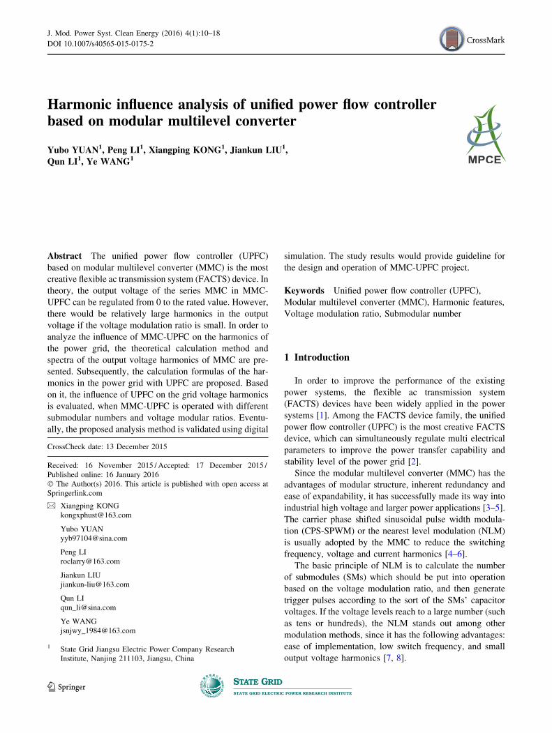
The topology of the MMC is depicted in Fig. 1 [15].
It can be found that the MMC consists of three parallel-
connected phase units, each with upper and lower arms.
The single arm has a modular structure with N series-
connected submodules (SMs) and a series inductance. Each
SM contains two insulated-gate bipolar transistor
(IGBT)/diode switches and a capacitor [4, 5].
The MMC-UPFC consists of shunt MMC and series
MMC which are connected back-to-back with the common
dc bus [13], as shown in Fig. 2. The shunt MMC interfaces
to the power grid through the shunt transformer, and can
absorb or generate controllable reactive power for AC bus
voltage regulation. Meanwhile, it can exchange the active
power with the power grid to maintain the dc bus voltage
constant. In addition, the series MMC interfaces to the
power grid through the series transformer. The power flow
of the transmission line can be regulated by adjusting the
magnitude and phase angle of the voltage injected by series
MMC [1, 2].
3 Harmonic spectra of MMC based on NLM
3.1 Basic principle of NLM
At present, the NLM is the most commonly used mod-
ulation technology for MMC, whose basic principle can be
elaborated as follows [7]:
According to the operating principle of MMC, the
number of SMs which are put into operation at every
switch cycle should always be N (N is number of the SMs
in the single arm). uref is the modulation voltage, VC is the
capacitor voltage of single SM.
With the increase of the instantaneous value of uref, the
number of SMs which are put into operation in the lower
arm should increase, and the number of SMs which are put
into operation in the upper arm should decrease at the same
time. Consequently, the output voltage would increase. At
every switch cycle, the numbers of SMs which are put into
operation in the upper and lower arms can be determined
according to (1).
iPa ipb
SMb1
SMb2
SMbN
ipc
SMc1
SMc2
SMcN
iNa iNb
id
Udc O
P
N
a b cVsaRs
Rs
Rs
Ls
Ls
Ls
Vsb
Vsc
D2
+VC
T1
T2
D1
Vc1
MMC SM
Phase unit Arm
SMa1
SMa2
SMaN
SMb1
SMb2
SMbN
SMc1
SMc2
SMcN
upa
una
SMaN
SMa2
SMa1
isa
isb
isc
iNc
Fig. 1 The topology of MMC
Fig. 2 System structure of UPFC
Harmonic influence analysis of unified power flow controller based on modular multilevel converter 11
123
Page 3
np ¼N
2� uref
VC
� �; 0� np �N
nn ¼N
2þ uref
VC
� �; 0� nn �N
8>>><>>>:
ð1Þ
where np is the number of SMs which are put into operation
in the upper arm; nn is the number of SMs which are put
into operation in the lower arm; [x] is the integer which is
the closest to x.
Theoretically, the error between the output voltage and
the instantaneous value of the modulation voltage can be
controlled within ±VC/2.
3.2 Analysis on the output voltage harmonics
of MMC
Assume that the modulation voltage of phase j (which is
denoted by uref j, and j represents a, b and c) is the sinu-
soidal wave and can be expressed as
uref j ¼ Um sin xt ð2Þ
where Um is the peak value of the modulation voltage.
According to the definition given in [2], the voltage
modulation ratio m can be expressed in (3).
m ¼ Um
12Udc
ð3Þ
where Udc is the dc bus voltage.
Assume each SM has the same capacitor voltage, then
Udc ¼ NVc ð4Þ
Hence, the following expression can be obtained.
uref j ¼mN
2VC sin xt ð5Þ
Then the numbers of SMs which are put into operation
in the upper and lower arms of the j phase unit are
npj ¼N
2� mN
2sin xt
� �; 0� npj �N
nnj ¼N
2þ mN
2sin xt
� �; 0� nnj �N
8>>><>>>:
ð6Þ
Hence, the output voltage of phase j is
uvj ¼unj � upj
2¼ mN
2sinxt
� �VC ¼ KVC ð7Þ
where upj and unj are respectively the upper arm voltage
and lower arm voltage of the phase j unit; K is the integer
and satisfies the following condition:
K � 1
2\
mN
2sin xt�K þ 1
2ð8Þ
Taking the MMC with 11 voltage levels for example,
Fig. 3 depicts the modulation voltage and the output
voltage of MMC.
In Fig. 3, Kmax is the number of the voltage levels in the
first quarter period (for the MMC with 11 voltage levels,
Kmax should be 5). The electrical angles of each voltage
level are respectively denoted by h1,…,hK,…,hKmax.According to (8), (9) can be obtained.
�mN
2� 1
2�K\
mN
2þ 1
2ð9Þ
Meanwhile, K should satisfy the following condition:
�N
2�K� N
2ð10Þ
Since it is an integer, Kmax should be
Kmax ¼ minm � N2
þ 1
2
� �;N
2
� �ð11Þ
where xb c is the largest integer that smaller than x, and min
(a,b) is to obtain the smaller one of a and b.
Besides, hK should satisfy the following expression.
K � 1
2¼ mN
2sinðhKÞ; K ¼ 1; 2; � � � ;Kmax ð12Þ
Hence,
hK ¼ arcsin2K � 1
m � N
� �; K ¼ 1; 2; � � � ;Kmax ð13Þ
Moreover, apply Fourier decomposition to the output
voltage of MMC, and (14) can be obtained.
uvj ¼ a0j þX
s¼1;2;���½asj cosðsxtÞ þ bsj sinðsxtÞ� ð14Þ
As Fig. 3 shows, output voltage of MMC is odd symmetry,
subsequently,
as ¼ 0; s ¼ 0; 1; 2; � � � ð15Þbs ¼ 0; s ¼ 2; 4; 6 � � � ð16Þ
0
uva Output voltage uvj
Modulation voltage uref j
VC0.5VC
1.5VC
2.5VC2VC
3VC
4VC3.5VC
4.5VC5VC
θ1θ2θ3 π/2θKmax θ
Fig. 3 Modulation voltage and output voltage of MMC
12 Yubo YUAN et al.
123
Page 4
bs ¼8
T
Z T4
0
uvj sinðsxtÞdt ¼
8
xT
XKmax
K¼1
Z hKþ1
hK
KVc sinðshÞdh; s ¼ 1; 3; 5; � � � ¼
4Vc
p1
s
XKmax
K¼1
cosðshKÞ
ð17Þ
where hKmaxþ1 ¼ p=2.Hence, the output voltage of MMC can be expressed by
uvj ¼4Vc
p
Xs¼1;3;���
1
s
XKmax
K¼1
cosðshKÞ" #
� sinðsxtÞ ð18Þ
It can be found that there are odd harmonics, but no even
harmonic in the output voltage of MMC. Moreover, the
content of each harmonic can be calculated with (19).
HuvjðsÞ ¼1s
PKmax
K¼1
cosðshKÞ
PKmax
K¼1
cosðhKÞs ¼ 3; 5; 7; � � � ð19Þ
4 Harmonic analysis of UPFC
Since the output voltage of the shunt MMC in UPFC is
always close to the rated value, and the voltage modulation
ratio is close to 1.0, the harmonics in the output voltage of
the shunt MMC and their influence on the power grid are
very small. Hence, the harmonics in the output voltage of
the shunt MMC is not discussed here.
In order to study the influence of the series MMC in
UPFC on the harmonics of the power grid, Fig. 4 gives the
equivalent circuit of the power grid with UPFC.
In Fig. 4, the series part of UPFC (consists of series
MMC and series transformer) is entirely represented by the
equivalent voltage source ev which is series-connected in
the transmission line MN at Bus M. The equivalent system
sources at the two terminals are represented by em and en,
the equivalent inductances of the two voltage sources are
respectively denoted by Lm and Ln. Besides, the resistance
of the transmission line MN is ignored since it is very
small, and the inductance is Ll.
It can be obtained from Fig. 4 that
em ¼ ev þ en þðLm þ Ll þ LnÞdi
dtð20Þ
un ¼ en þ Lndi
dt
um ¼ em � Lmdi
dt
8><>: ð21Þ
Accordingly, the voltages of Bus M and Bus N which
are denoted by um and un are respectively:
un ¼emLn þ enðLm þ LlÞ
Lm þ Ll þ Ln� Ln
Lm þ Ll þ Lnev
um ¼ emðLl þ LnÞ þ enLm
Lm þ Ll þ Lnþ Lm
Lm þ Ll þ Lnev
8>><>>:
ð22Þ
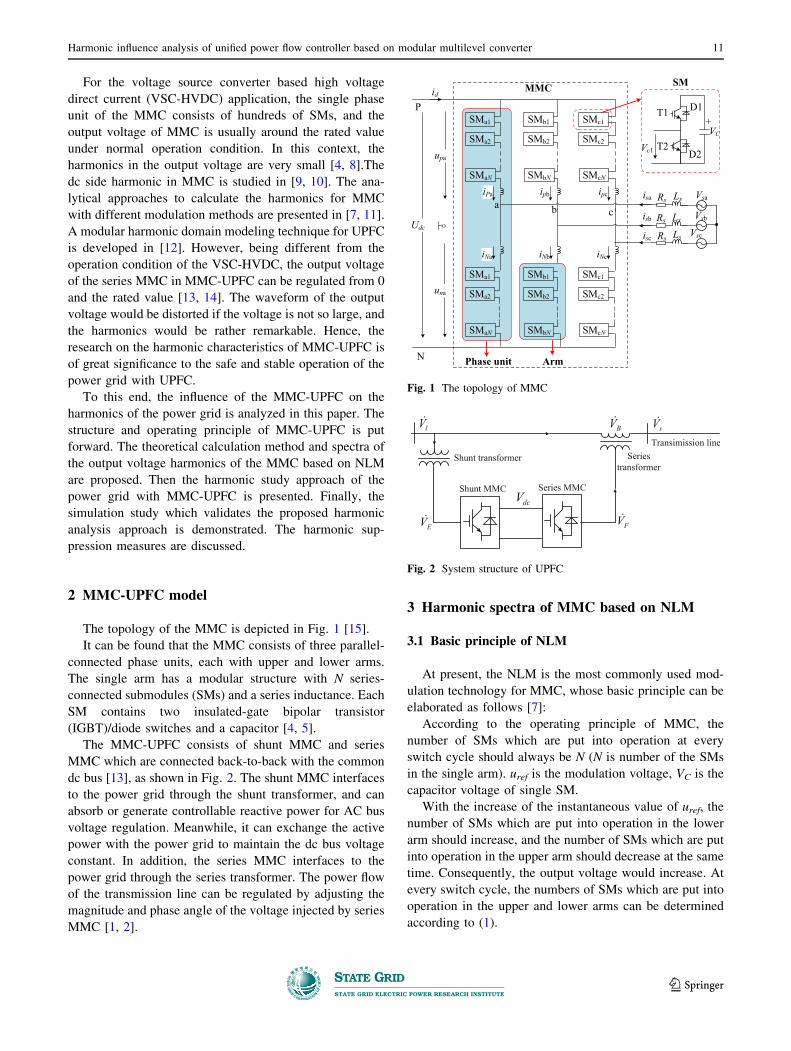
Moreover, the equivalent circuit of the series
transformer in UPFC is given in Fig. 5.
In Fig. 5, uv is the output voltage of the series MMC, epis the voltage of the series transformer’s primary winding.
ep = kuv, and k is the turns ratio of the series transformer.
LT and LTm are respectively the equivalent leakage induc-
tance and magnetic inductance of the series transformer.
Hence, the detailed equivalent circuit of the power grid
with UPFC is depicted in Fig. 6.
By replacing Ll and ev in (22) respectively with Ll?LTand kuvj, the following expression can be obtained.
un ¼emLnþ enðLmþLlþLTÞ
LmþLlþLT þLn� Ln
LmþLlþLT þLnk �uvj
um ¼ emðLlþLT þLnÞþ enLm
LmþLlþLT þLnþ Lm
LmþLlþLT þLnk �uvj
8>><>>:
ð23Þ
It can be found that um and un both consist of two parts.
The first parts are fundamental frequency components and
only related to the equivalent system sources. The second
parts are related to the output voltage of the series MMC.
Hence, there are also odd harmonics in um and un.
Rewrite (23) in the following forms:
un ¼ An sinðxt þ unÞ þ Bn � uvjum ¼ Am sinðxt þ umÞ þ Bm � uvj
(ð24Þ
Lm LnLli
um unem
e v
en
Bus M Bus N
Fig. 4 The equivalent circuit of the power grid with UPFC
LT
ep evLTm
i1:k
uv
Fig. 5 Equivalent circuit of the series transformer
Harmonic influence analysis of unified power flow controller based on modular multilevel converter 13
123
Page 5
where An, un, Am and um can be determined by applying
triangular calculation to the first parts of um and un. Bn and
Bm satisfy the following conditions.
Bn ¼ � Lnk
Lm þ Ll þ LT þ Ln
Bm ¼ Lmk
Lm þ Ll þ LT þ Ln
8><>: ð25Þ
According to (17), (18) and (24), the harmonic contents
in um and un can be calculated with (26).
HunðsÞ ¼Bnbsffiffiffiffiffiffiffiffiffiffiffiffiffiffiffiffiffiffiffiffiffiffiffiffiffiffiffiffiffiffiffiffiffiffiffiffiffiffiffiffiffiffiffiffiffiffiffiffiffiffiffiffiffiffiffiffiffiffiffiffiffiffi
A2n þ 2Anb1Bn cosun þ b1Bn
2q
HumðsÞ ¼Bmbsffiffiffiffiffiffiffiffiffiffiffiffiffiffiffiffiffiffiffiffiffiffiffiffiffiffiffiffiffiffiffiffiffiffiffiffiffiffiffiffiffiffiffiffiffiffiffiffiffiffiffiffiffiffiffiffiffiffiffiffiffiffiffiffiffiffi
A2m þ 2Amb1Bm cosum þ b1Bm
2q
8>>>>><>>>>>:s ¼ 3; 5; 7; � � �
ð26Þ
5 Simulation analysis
5.1 Output voltage harmonics of MMC
For different voltage modulation ratios, Fig. 7 demon-
strates the harmonic contents in the output voltage of
MMC, whose orders are not larger than 51. It is noted that
N = 26, Udc = 40 kV.
Besides, for different SM numbers, the relationship
between the total harmonic distortion (THD) in the output
voltage of MMC and the voltage modulation ratio m is
given in Fig. 8.
According to the results shown in Fig. 7 and Fig. 8, the
following conclusions can be drawn.
1) There are odd harmonics in the output voltage of
MMC.
2) If m B 1.0, with the increase of m, the harmonic
contents would decrease. When m reaches to 1.0, the
harmonic contents are the smallest. If m[ 1.0, the
harmonic contents would increase greatly.
3) With the increase of N, the harmonic contents in the
output voltage ofMMCwould decrease. However, ifN is
larger than 20,with the increase ofN, the improvement of
the harmonic contents would be not that significant.
5.2 Harmonic analysis of the power grid with UPFC
The parameters of the components in Fig. 6 are:
Lm = 0.1 H, Ln = 0.2 H, Ll = 0.02 H, LT = 0.5 H,
k = 26.5/20.8 kV, em = 127sin(xt?0.175) kV, en = 127-
sin xt kV.
Lm LnLli
um unem en
LTep
ev
1:k
uvj
Seires transformer
Bus M Bus N
Fig. 6 The detailed equivalent circuit of the power grid with UPFC
0 0.005 0.010 0.015 0.020-5
0
5
Time(s)(a) Output voltage of MMC with
m=0.2
Vol
tage
(kV
)
urefuv
0 20 40 600
5
10
Harmonic order
0 0.005 0.010 0.015 0.020Time(s)
00
20 40 60Harmonic order
0 0.005 0.010 0.015 0.020Time(s)
0 20 40 60Harmonic order
(b) Harmonic spectra with m=0.2
Har
mon
ic
cont
ent(%
)
-100
10
(c) Output voltage of MMC with m=0.6
Vol
tage
(kV
)
urefuv 1
2
(d) Harmonic spectra with m=0.6
Har
mon
ic
cont
ent(%
)
-20
0
20
(e) Output voltage of MMC with m=1.0
Vol
tage
(kV
)
urefuv
0
0.5
1.0
(f) Harmonic spectra with m=1.0
Har
mon
ic
cont
ent(%
)
Fig. 7 Output voltages of MMC and the harmonic contents
0.2 0.4 0.6 0.8 1.0 1.2 1.4 1.60
5
10
15
20
25
30
35
m
THD
(%)
N=10N=20N=26N=40N=50
Fig. 8 Relationship between THD of output voltage and modulate
ratio
14 Yubo YUAN et al.
123
Page 6
For N = 26 and Udc = 40 kV, the waveforms of um and
un, as well as their harmonic contents with different voltage
modulation ratios are depicted in Fig. 9 and Fig. 10.
Besides, for different SM numbers, the relationships
between the THD of um, un and the voltage modulation
ratio m are given in Fig. 11.
Based on the results shown in Fig. 9, Fig. 10 and
Fig. 11, the following conclusions can be drawn.
1) There are odd harmonics in the bus voltages, related to
the odd harmonics in the output voltage of MMC.
2) If m\ 1.0, with the increase of m, the harmonic
contents decreases slightly. When m reaches to 1.0, the
harmonic contents are the smallest. If m[ 1.0, the
harmonic contents would increase greatly with the
increase of m.
3) With the increase of N, the harmonic contents in the
bus voltages would decrease. However, if N is larger
than 20, with the increase of N, the improvement of the
harmonic contents would be not that significant.
5.3 Simulation results
The simulation model of the power grid with UPFC is
built using PSCAD/EMTDC, where N = 26, Udc = 40 kV,
and NLM is adopted. Besides, the parameters of the power
grid are configured according to a practical UPFC project.
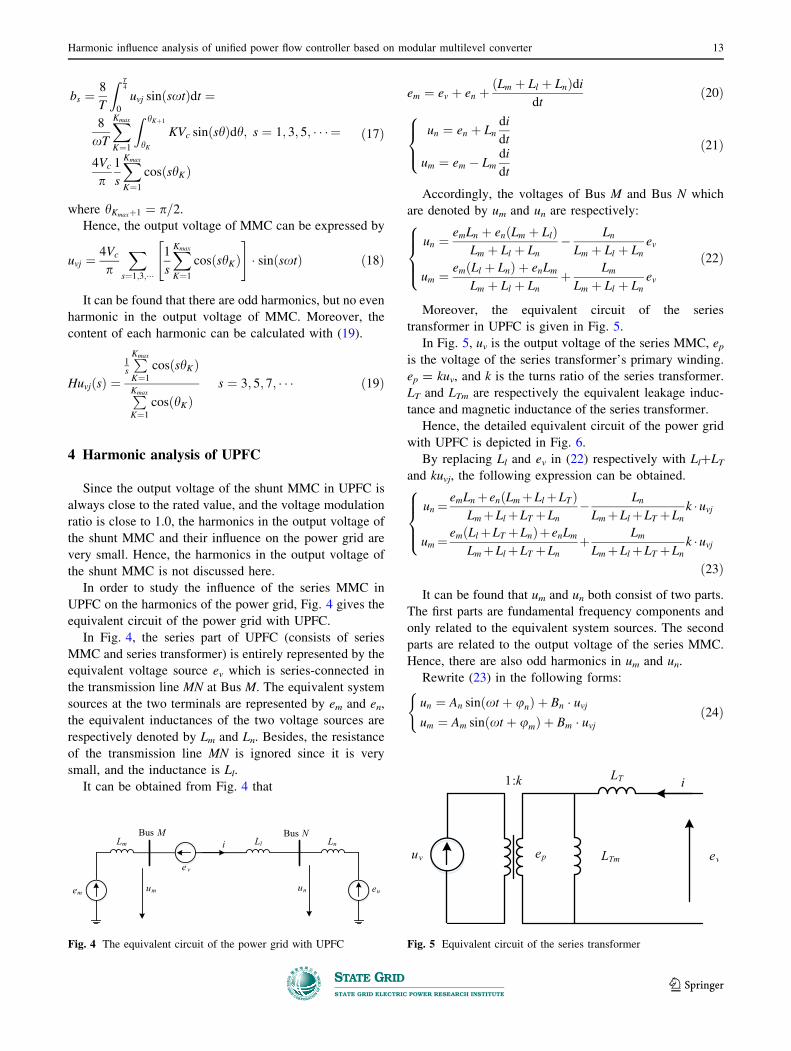
With different voltage modulation ratios, Fig. 12 shows
the comparison of the theoretical results and simulation
results of the series MMC’s output voltage, and Fig. 13
demonstrates the comparison of the theoretical results and
simulation results of the system voltage.
0 0.005 0.010 0.015 0.020-200-100
0100200
Time(s)(a) Voltage of Bus N with
m=0.8
Vol
tage
(kV
)
0 20 40 60
0.01
0.02
0.03
Harmonic order(b) Harmonic spectra with
m=0.8
Har
mon
ic c
onte
nt (%
)
0 0.005 0.010 0.015 0.020-200-100
0100200
Time(s)(c) Voltage of Bus M with
m=0.8
Vol
tage
(kV
)
0 20 40 60
0.005
0.010
0.015
Harmonic order(d) Harmonic spectra with
m=0.8
Ham
onic
con
tent
(%)
Fig. 9 Bus voltages and harmonic contents (m = 0.8)
0 0.005 0.010 0.015 0.020-200-100
0100200
Time(s)(a) Voltage of Bus N with
m=0.4
Vol
tage
(kV
)
0 20 40 60
0.02
0.04
Harmonic order(b) Harmonic spectra with
m=0.4
Har
mon
ic c
onte
nt (%
)
0 0.005 0.010 0.015 0.020-200-100
0100200
Time(s)
(c) Voltage of Bus M with m=0.4
Vol
tage
(kV
)
0 20 40 60
0.0050.0100.0150.020
Harmonic order
(d) Harmonic spectra with m=0.4
Har
mon
ic c
onte
nt (%
)
Fig. 10 Bus voltages and harmonic contents (m = 0.4)
0.2 0.4 0.6 0.8 1.0 1.2 1.4 1.60
0.1
0.2
0.3
0.4
0.5
0.6
0.7
m
THD
(%)
N=10N=20N=26N=40N=50
(a) THD of voltage at Bus N
0.2 0.4 0.6 0.8 1.0 1.2 1.4 1.60
0.05
0.10
0.15
0.20
0.25
0.30
0.35
m
THD
(%)
N=10N=20N=26N=40N=50
(b) THD of voltage at Bus M
Fig. 11 Relationships between THD of bus voltages and modulate
ratio
Harmonic influence analysis of unified power flow controller based on modular multilevel converter 15
123
Page 7
It can be found that the simulation results about the
harmonic contents of the series MMC’s output voltage and
the system voltage agree with the theoretical results rather
well, which validate the effectiveness of the proposed
theoretical analysis method.
6 Influence factors of harmonics in the power gridand countermeasures
6.1 Influence analysis of UPFC on harmonics
It can be found from the above analysis that the har-
monics of the power grid caused by MMC-UPFC are
related to the SM number, voltage modulation ratio, rated
dc bus voltage of UPFC, and the AC system parameters.
1) Influence of the AC system voltage
According to (23), the smaller the voltage of the AC
system is, the larger the influence of UPFC on the
harmonics of the power grid is. In order to validate the
theoretical analysis result, Table 1 shows the relation-
ship between the AC system voltage and the maximum
harmonic content, THD in the bus voltage of the
power grid. It is noted that m = 0.5, Udc = 40 kV, and
N = 20.
2) Influence of rated dc bus voltage of UPFC
For the same SM number, with the increase of the
rated dc bus voltage of UPFC, the single SM’s
capacitor voltage would also increase. Hence, the
number of the output voltage levels would decrease
when the voltage modulation ratio is small. In this
context, the influence of UPFC on the bus voltage
harmonics of the power grid would be larger with the
0 0.01 0.02 0.03 0.04-5
0
5
Time(s)(a) Output voltage of MMC with
m=0.2
Vol
tage
(kV
)
0 0.01 0.02 0.03 0.04-20
-10
0
10
20
Time(s)(c) Output voltage of MMC with
m=0.6
Vol
tage
(kV
)
3 5 7 9 11131517192123250
0.5
1.0
1.5
2.0
Harmonic order(d) Harmonic spectra with
m=0.6
Har
mon
ic c
onte
nt (%
)
3 5 7 9 11131517192123250
5
10
Harmonic order(b) Harmonic spectra with
m=0.2
Har
mon
ic c
onte
nt (%
)
simulation calculation
simulation calculation
Fig. 12 Output voltages of series MMC and the harmonic contents
Table 1 Maximum harmonic content and THD under different AC
system voltages
AC system voltage
(kV)
Maximum harmonic content
(%)
THD
(%)
10 1.73 3.98
35 0.34 0.79
110 0.10 0.23
220 0.05 0.11
500 0.02 0.05
Table 2 Maximum harmonic content and THD under different rated
dc bus voltages
Rated dc bus voltage
(kV)
Maximum harmonic content
(%)
THD
(%)
40 0.049 0.114
80 0.101 0.231
100 0.127 0.291
150 0.194 0.447
200 0.265 0.611
Table 3 Maximum harmonic content and THD with different Ln
Ln (H) Maximum harmonic content (%) THD (%)
0.1 0.028 0.064
0.2 0.049 0.114
0.5 0.092 0.211
1.0 0.128 0.298
1.5 0.148 0.342
0 0.01 0.02 0.03 0.04-200-100
0100200
Time(s)
(a) System voltage with m=0.2
Vol
tage
(kV
)
0 5 10 15 20 250
0.050.100.150.20
Harmonic order
(b) Harmonic spectra with m=0.2
Har
mon
ic c
onte
nt(%
)
simulation calculation
0 0.01 0.02 0.03 0.04-200
-100
0
100
200
Time(s)
(c) System voltage with m=0.6
Vol
tage
(kV
)
0 5 10 15 20 250
0.05
0.10
0.15
Harmonic order
(d) Harmonic spectra with m=0.6
Har
mon
ic c
onte
nt(%
)
simulation calculation
Fig. 13 System voltage and harmonic contents
16 Yubo YUAN et al.
123
Page 8
increase of the rated dc bus voltage of UPFC. Table 2
shows the relationship between the rated dc bus
voltage of UPFC and the maximum harmonic content,
THD in the bus voltage of the power grid. It is noted
that m = 0.5, Uac = 220 kV, and N = 20.
3) Influence of AC system parameters
As shown in (23), the influence of UPFC on the
harmonics of the power grid would increase with the
decrease of the short circuit capability of the AC
system. In order to validate the theoretical analysis
result, Table 3 shows the relationship between Ln and
the maximum harmonic content, THD in the bus
voltage of the power grid. Noted that m = 0.5,
Uac = 220 kV, Udc = 40 kV and N = 20.
From the above theoretical analysis and simulation
study, it can be found that if the AC system voltage is
rather high, its influence on the harmonics in the bus
voltage of the power grid is rather small and can be
ignored. If the rated dc bus voltage of the UPFC is large, or
the short circuit capability of the AC system is weak, the
influence of UPFC on the bus voltage harmonics of the
power grid is relatively larger, which should be taken into
consideration for the UPFC project design and operation.
Meanwhile, special countermeasures should be taken to
improve the power quality of the power grid.
6.2 Countermeasures
In order to reduce the influence of the MMC-UPFC on
the harmonics of the power grid, some special counter-
measures are presented, such as optimizing the planning
and design of the UPFC project, as well as improving the
control scheme of UPFC.
1) During the planning and design stage of the UPFC
project, the access point of UPFC, AC system voltage
and UPFC parameters (such as rated dc bus voltage
and SM number) should be chosen reasonably. More-
over, the filters should be installed when necessary,
though the investment would increase.
2) If the voltage modulation ratio is small, the number of
the output voltage levels would decrease, which
increase the harmonic contents. In order to address
the above issue, improved control scheme of UPFC
should be adopted. For example, the coordinate
control of the series MMC and shunt MMC should
be implemented, to improve the number of output
voltage levels by reducing the single SM’s capacitor
voltage. Moreover, the margin of the voltage modu-
lation ratio, redundant SMs and on-load tap regulation
switch of the shunt transformer should be employed to
increase the number of the output voltage levels. The
above improved control scheme of UPFC would not
increase the investment, and can improve the control
and operation feasibility of UPFC.
The advantage of increasing number of output voltage
levels on the harmonic suppression is analyzed as
follows.
If N = 30, Udc = 40 kV, then the single SM’s capacitor
voltage Usm should be 1.33 kV. Assuming m = 0.8, the
peak value of the output voltage of the shunt MMC is
UacP ¼ mUdc
2¼ 20� 0:8 ¼ 16 kV ð27Þ
On condition that the output voltage of the shunt MMC
keeps constant, the following expressions can be obtained.
Udc ¼ 2UacP
m¼ 2UacP ¼ 32 kV
Usm ¼ 2UacP
Ne
¼ 1:067 kV
8><>: ð28Þ
It can be found that Usm reduces to be 1.067 kV.
Furthermore, if the redundant SMs whose number is 5
are put into operation, Usm would reduce to be 0.914 kV, as
given in (29):
Usm ¼ 2UacP
Ne þ Nred
¼ 0:914 kV ð29Þ
where Nred is the number of the redundant SMs.
For the different AC system voltages, the numbers of the
output voltage levels with and without reducing single
SM’s capacitor voltage are given in Table 4.
It can be found that with reducing single SM’s capacitor
voltage, the number of the output voltage levels can be
increased to reduce the harmonics injected by UPFC.
7 Conclusion
According to the operation of MMC-UPFC, the har-
monics of the MMC-UPFC is studied in this paper. Based
on the harmonic features of MMC and equivalent circuit of
the power grid with UPFC, the harmonic spectra analysis
Table 4 The level numbers with different AC system voltage
Peak value of
AC system
voltage (kV)
Level number without
reducing single SM’s
capacitor voltage
Level number with
reducing single SM’s
capacitor voltage
1.0 3 3
1.6 3 5
2.5 5 7
3.7 7 9
4.5 7 11
Harmonic influence analysis of unified power flow controller based on modular multilevel converter 17
123
Page 9
method of the power grid is studied. Moreover, the influ-
ence of SM number, voltage modulation ratio, and AC
system voltage on the harmonics of the power grid are
analyzed. The effectiveness of the proposed analysis
method is validated using PSCAD/EMTDC simulation.
Finally, the countermeasures which can help to suppress
the harmonics in the power grid are presented. The study
results of this paper can provide guideline for the design
and operation of the UPFC project.
Acknowledgment This work was supported by State Grid Corpo-
ration of China (SGCC)’s Major Science and Technology Demon-
strative Project of UPFC in West Nanjing Power Grid (No. SGCC-
2015-011).
Open Access This article is distributed under the terms of the
Creative Commons Attribution 4.0 International License (http://
creativecommons.org/licenses/by/4.0/), which permits unrestricted
use, distribution, and reproduction in any medium, provided you give
appropriate credit to the original author(s) and the source, provide a
link to the Creative Commons license, and indicate if changes were
made.
References
[1] Li CB, Xiao LW, Cao YJ et al (2014) Optimal allocation of
multi-type FACTS devices in power systems based on power
flow entropy. J Mod Power Syst Clean Energy 2(2):173–180.
doi:10.1007/s40565-014-0059-x
[2] Gyugyi L, Schauder CD, Williams SL et al (1995) The unified
power flow controller: a new approach to power transmission
control. IEEE Trans Power Deliv 10(2):1085–1097
[3] Dorn J, Huang H, Retzmann D (2007) Novel voltage-sourced
converters for HVDC and FACTS application. In: Proceedings
of the CIGRE symposium on system development and asset
management under restructuring, Osaka, Japan, 1–4 Nov 2007, 8
pp
[4] Song JY, Feng XQ, Cui FB et al (2014) Dynamic modeling and
internal characteristic simulation research of MMC-UPFC. Proc
CSEE 34:67–75 (in Chinese)
[5] Tu QR, Xu Z, Zheng X et al (2010) Mechanism analysis on the
circulating current in modular multilevel converter based
HVDC. High Volt Eng 36(2):547–552 (in Chinese)
[6] Wang SS, Zhou XX, Tang GF et al (2011) Modeling of modular
multi-level voltage source converter. Proc CSEE 31(24):1–8 (in
Chinese)
[7] Tu QR, Xu Z (2011) Impact of sampling frequency on harmonic
distortion for modular multilevel converter. IEEE Trans Power
Deliv 26(1):298–306
[8] Guan Y, Xu Z, Tu QR et al (2010) Nearest level modulation for
modular multilevel converters in HVDC transmission. Autom
Electr Power Syst 34(2):48–52 (in Chinese)
[9] Wang F, Xu Z, Huang Y et al (2010) DC harmonic current
calculation for HVDC systems based on the classical transmis-
sion line model. In: Proceedings of the 2010 international con-
ference on power system technology, Hangzhou, China, 24–28
Oct 2010, 5 pp
[10] Zhang ZR, Xu Z, Xue YL et al (2015) DC-side harmonic cur-
rents calculation and DC-loop resonance analysis for an LCC–
MMC hybrid HVDC transmission system. IEEE Trans Power
Deliv 30(2):642–651
[11] Wang LQ, Lin P, Li JL et al (2004) Harmonic characteristic of
sample time staggered space vector modulation for multi-mod-
ular or multilevel converters. In: Proceedings of the IEEE 35th
annual power electronics specialists conference, vol 6, Aachen,
Germany, 20–25 Jun 2004, pp 4554–4557
[12] Collins C, Watson N, Wood A (2006) UPFC modeling in the
harmonic domain. IEEE Trans Power Deliv 21(2):933–938
[13] Zhang ZH, Jiang DZ (2012) Control strategy simulation of
UPFC based on modular multilevel converters. Power Syst Prot
Control 40(3):73–77 (in Chinese)
[14] Jing P, Zhou F, Song JY et al (2013) Design and simulation of
unified power flow controller based on modular multilevel
converter. Power Syst Technol 37(2):356–361 (in Chinese)
[15] Wang PY, Zhang XP, Coventry PF et al (2014) Control and
protection strategy for MMC MTDC system under converter-
side AC fault during converter blocking failure. J Mod Power
Syst Clean Energy 2(3):272–281. doi:10.1007/s40565-014-
0064-0
Yubo YUAN received the Ph.D. degree in School of Electrical
Engineering from Southeast University, Nanjing, China, in 2004.
Currently, he is a professorate engineer in State Grid Jiangsu Electric
Power Company Research Institute. His research interest is protective
relaying.
Peng LI received the Ph.D. degree in School of Electrical Engineer-
ing from Xi’an Jiaotong University, Xi’an, China, in 2011. Currently,
he is a senior engineer in State Grid Jiangsu Electric Power Company
Research Institute. His research interest is control and protection of
HVDC.
Xiangping KONG received the Ph.D. degree in School of Electrical
and Electronic Engineering from Huazhong University of Science and
Technology, Wuhan, China, in 2014. Currently, he is an engineer in
State Grid Jiangsu Electric Power Company Research Institute. His
research interest is protective relaying.
Jiankun LIU received the Master Degree in School ofElectrical
Engineering from Xi’an Jiaotong University,Xi’an, China, in 2004.
Currently, he is a Senior Engineer inState Grid Jiangsu Electric Power
Company ResearchInstitute. His research interest is power system
analysis.
Qun LI received the Ph.D. degree in School of Electrical Engineeringfrom Southeast University, Nanjing, China, in 1999. Currently, he is a
professorate senior engineer in State Grid Jiangsu Electric Power
Company Research Institute. His research interest is power quality
analysis and renewable power integration.
Ye WANG received the Ph.D. degree in School of Electrical
Engineering from Southeast University, Nanjing, China, in 2013.
Currently, he is an engineer in State Grid Jiangsu Electric Power
Company Research Institute. His research interest is control and
protection of HVDC.
18 Yubo YUAN et al.
123


![Power Quality Improvement using Voltage Source Converter ... · power quality offered by the harmonic sensitive loads [5]. 2. THE UNIFIED POWER QUALITY CONDITIONER nified Power Quality](https://static.documents.pub/doc/80x56/5ed3578b4e15b65b4670b614/power-quality-improvement-using-voltage-source-converter-power-quality-offered.jpg)
![i .] APPROXIMATING HARMONIC FUNCTIONS 499€¦ · APPROXIMATING HARMONIC FUNCTIONS 499 THE APPROXIMATION OF HARMONIC FUNCTIONS BY HARMONIC POLYNOMIALS AND BY HARMONIC RATIONAL FUNCTIONS*](https://static.documents.pub/doc/80x56/5f0873ba7e708231d42214c2/i-approximating-harmonic-functions-499-approximating-harmonic-functions-499-the.jpg)


