68
Total Motion Control Harmonic Drive ™ actuator Precision Gearing & Motion Control H ollow S Haft a ctuatorS SHA Series
| Date post: | 12-Jul-2015 |
| Category: |
Technology |
| Upload: | electromate |
| View: | 64 times |
| Download: | 4 times |
Total Motion Control
Harmonic Drive™actuatorP r e c i s i o n G e a r i n g & M o t i o n C o n t r o l
H o l l o w S H a f t a c t u a t o r SSHA Series
AC Servo Actuator
SHA series manual
_ Thank you for purchasing our SHA series AC Servo Actuator.
_ Improper handling or use of this product may result in an accidentor reduced life of the product. Read this document carefully anduse the product correctly so that the product can be used safelyfor many years to come.
_ Product specifications are subject to change without notice.
_ Keep this manual in a convenient location and refer to it asnecessary when operating or maintaining the actuator.
_ The end user of the actuator should have a copy of this manual.
ISO14001(Hotaka plant)ISO9001
ELECTROMATEToll Free Phone (877) SERVO98
Toll Free Fax (877) SERV099www.electromate.com
Sold & Serviced By:
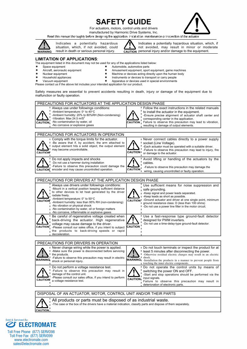
SAFETY GUIDEFor actuators, motors, control units and driversmanufactured by Harmonic Drive Systems, Inc.
Indicates a potentially hazardoussituation, which, if not avoided, couldresult in death or serious personal injury.
Indicates a potentially hazardous situation, which, ifnot avoided, may result in minor or moderatepersonal injury and/or damage to the equipment.
LIMITATION OF APPLICATIONS:The equipment listed in this document may not be used for any of the applications listed below: Space equipment Automobile, automotive parts Aircraft, aeronautic equipment Amusement equipment, sport equipment, game machines Nuclear equipment Machine or devices acting directly upon the human body Household appliances Instruments or devices to transport or carry people Vacuum equipment Apparatus or devices used in special environmentsPlease contact us if the above list includes your intended application for our product.
Safety measures are essential to prevent accidents resulting in death, injury or damage of the equipment due tomalfunction or faulty operation.
PRECAUTIONS FOR ACTUATORS AT THE APPLICATION DESIGN PHASEAlways use under followings conditions:-Ambient temperature: 0° to 40°C-Ambient humidity: 20% to 80%RH (Non-condensing)-Vibration: Max 24.5 m/S2
-No contamination by water, oil-No corrosive or explosive gases
Follow the exact instructions in the related manualsto install the actuator in the equipment.-Ensure precise alignment of actuator shaft center andcorresponding center in the application.Failure to observe this precaution may lead to vibration,resulting in damage of output elements.
PRECAUTIONS FOR ACTUATORS IN OPERATIONComply with the torque limits for the actuator.-Be aware that if, by accident, the arm attached tooutput element hits a solid object, the output elementmay become uncontrollable.
Never connect cables directly to a power supplysocket (Line Voltage).-Each actuator must be operated with a suitable driver.-Failure to observe this precaution may lead to injury, fireor damage to the actuator.
Do not apply impacts and shocks-Do not use a hammer during installation-Failure to observe this precaution could damage theencoder and may cause uncontrolled operation.
Avoid lifting or handling of the actuators by thecables.-Failure to observe this precaution may damage thewiring, causing uncontrolled or faulty operation.
PRECAUTIONS FOR DRIVERS AT THE APPLICATION DESIGN PHASEAlways use drivers under followings conditions:-Mount in a vertical position keeping sufficient distanceto other devices to let heat generated by the driverradiate freely.-Ambient temperature: 0° to 50°C-Ambient humidity: less than 95% RH (non-condensing)-No vibration or physical shock-No contamination by water, oil or foreign matters-No corrosive, inflammable or explosive gases
Use sufficient means for noise suppression andsafe grounding.-Keep signal and power leads separated.-Keep leads as short as possible.-Ground actuator and driver at one single point, minimumground resistance class: D (less than 100 ohms)-Do not use a power line filter in the motor circuit.
Be careful of regenerative voltage created whenback-driving the actuator. High regenerativevoltage may cause damage to the driver.-Please consult our sales office, if you intent to subjectthe products to back-driving speeds or rapiddecceleration.
Use a fast-response type ground-fault detectordesigned for PWM inverters.-Do not use a time-delay-type ground-fault detector.
PRECAUTIONS FOR DRIVERS IN OPERATIONNever change wiring while the power is applied.-Make sure the power is disconnected before servicingthe products.-Failure to observe this precaution may result in electricshock or personal injury.
Do not touch terminals or inspect the product for atleast 5 minutes after disconnecting the power.-Otherwise residual electric charges may result in an electricshock.-Installation the products in a manner to prevent people fromtouching the inner electric components.
Do not perform a voltage resistance test.-Failure to observe this precaution may result indamage of the control unit.-Please consult our sales office, if you intend to performa voltage resistance test.
Do not operate the control units by means ofswitching the power ON and OFF.-Start and stop operations should be performed via theinput signals.Failure to observe this precaution may result indeterioration of electronic parts.
DISPOSAL OF AN ACTUATOR, MOTOR, CONTROL UNIT AND/OR THEIR PARTS
All products or parts must be disposed of as industrial waste.-The case or the box of the drivers have a material indication, classify parts and dispose of them separately.
CAUTION CAUTION
CAUTION CAUTION
CAUTION CAUTION
CAUTIONWARNING
CAUTION CAUTION
CAUTION CAUTION
WARNING WARNING
CAUTION CAUTION
CAUTION
ELECTROMATEToll Free Phone (877) SERVO98
Toll Free Fax (877) SERV099www.electromate.com
Sold & Serviced By:
SHA series manual
-Contents 1 -
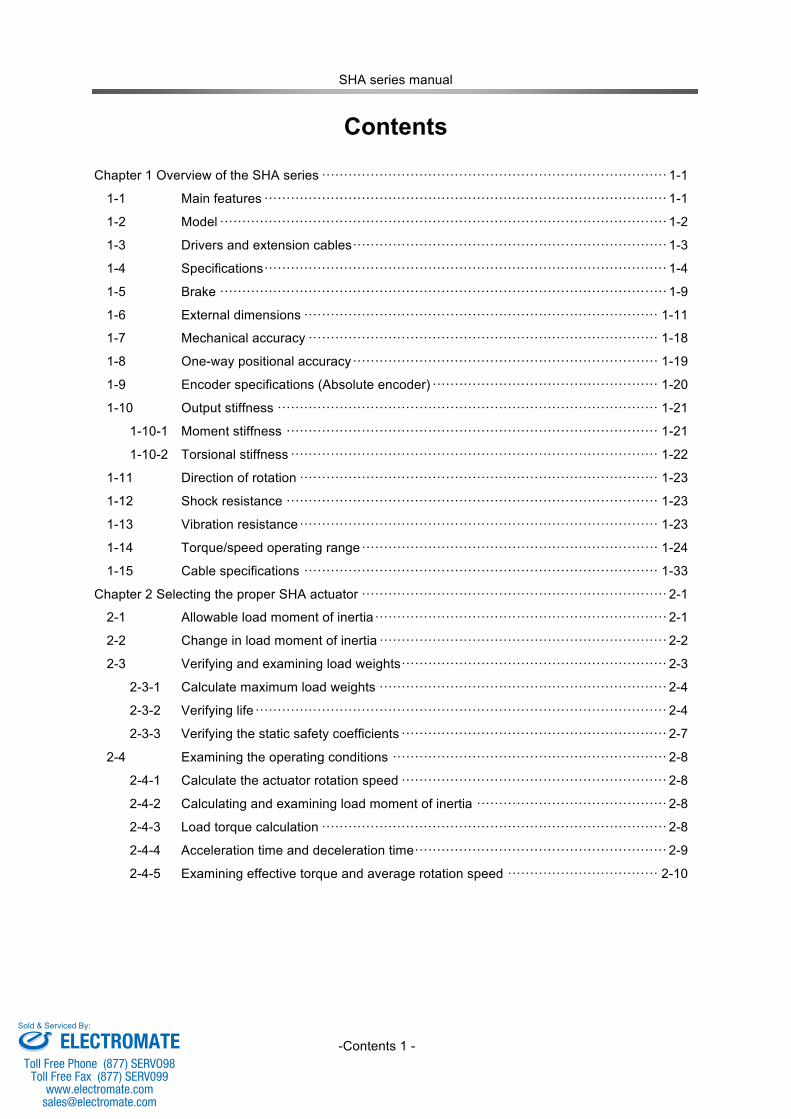
Contents
Chapter 1 Overview of the SHA series ·············································································· 1-1
1-1 Main features ··························································································· 1-1
1-2 Model ····································································································· 1-2
1-3 Drivers and extension cables ······································································· 1-3
1-4 Specifications ··························································································· 1-4
1-5 Brake ····································································································· 1-9
1-6 External dimensions ················································································ 1-11
1-7 Mechanical accuracy ··············································································· 1-18
1-8 One-way positional accuracy ····································································· 1-19
1-9 Encoder specifications (Absolute encoder) ··················································· 1-20
1-10 Output stiffness ······················································································ 1-21
1-10-1 Moment stiffness ···················································································· 1-21
1-10-2 Torsional stiffness ··················································································· 1-22
1-11 Direction of rotation ················································································· 1-23
1-12 Shock resistance ···················································································· 1-23
1-13 Vibration resistance ················································································· 1-23
1-14 Torque/speed operating range ··································································· 1-24
1-15 Cable specifications ················································································ 1-33
Chapter 2 Selecting the proper SHA actuator ····································································· 2-1
2-1 Allowable load moment of inertia ·································································· 2-1
2-2 Change in load moment of inertia ································································· 2-2
2-3 Verifying and examining load weights ···························································· 2-3
2-3-1 Calculate maximum load weights ································································· 2-4
2-3-2 Verifying life ····························································································· 2-4
2-3-3 Verifying the static safety coefficients ···························································· 2-7
2-4 Examining the operating conditions ······························································ 2-8
2-4-1 Calculate the actuator rotation speed ···························································· 2-8
2-4-2 Calculating and examining load moment of inertia ··········································· 2-8
2-4-3 Load torque calculation ·············································································· 2-8
2-4-4 Acceleration time and deceleration time ························································· 2-9
2-4-5 Examining effective torque and average rotation speed ·································· 2-10
ELECTROMATEToll Free Phone (877) SERVO98
Toll Free Fax (877) SERV099www.electromate.com
Sold & Serviced By:
SHA series manual
-Contents 2 -
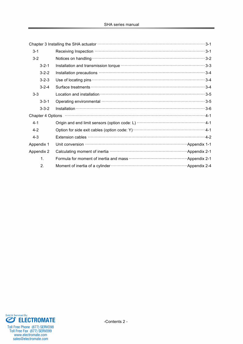
Chapter 3 Installing the SHA actuator ··············································································· 3-1
3-1 Receiving Inspection ················································································· 3-1
3-2 Notices on handling ··················································································· 3-2
3-2-1 Installation and transmission torque ······························································ 3-3
3-2-2 Installation precautions ·············································································· 3-4
3-2-3 Use of locating pins ··················································································· 3-4
3-2-4 Surface treatments ···················································································· 3-4
3-3 Location and installation ············································································· 3-5
3-3-1 Operating environmental ············································································ 3-5
3-3-2 Installation ······························································································· 3-6
Chapter 4 Options ······································································································· 4-1
4-1 Origin and end limit sensors (option code: L) ·················································· 4-1
4-2 Option for side exit cables (option code: Y) ····················································· 4-1
4-3 Extension cables ······················································································ 4-2
Appendix 1 Unit conversion ··········································································· Appendix 1-1
Appendix 2 Calculating moment of inertia ························································· Appendix 2-1
1. Formula for moment of inertia and mass ··········································· Appendix 2-1
2. Moment of inertia of a cylinder ························································ Appendix 2-4
ELECTROMATEToll Free Phone (877) SERVO98
Toll Free Fax (877) SERV099www.electromate.com
Sold & Serviced By:
Chapter 1 Overview of the SHA series
- 1-1 -
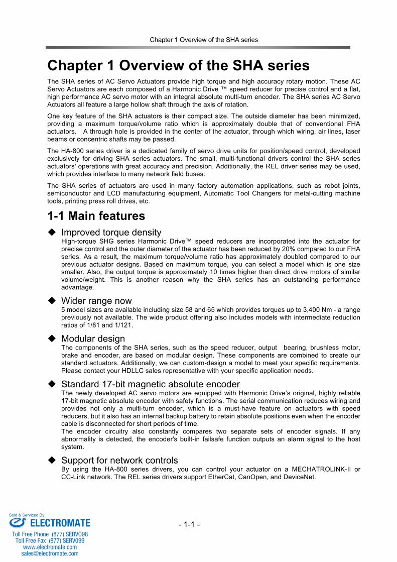
Chapter 1 Overview of the SHA series The SHA series of AC Servo Actuators provide high torque and high accuracy rotary motion. These AC Servo Actuators are each composed of a Harmonic Drive ™ speed reducer for precise control and a flat, high performance AC servo motor with an integral absolute multi-turn encoder. The SHA series AC Servo Actuators all feature a large hollow shaft through the axis of rotation.
One key feature of the SHA actuators is their compact size. The outside diameter has been minimized, providing a maximum torque/volume ratio which is approximately double that of conventional FHA actuators. A through hole is provided in the center of the actuator, through which wiring, air lines, laser beams or concentric shafts may be passed.
The HA-800 series driver is a dedicated family of servo drive units for position/speed control, developed exclusively for driving SHA series actuators. The small, multi-functional drivers control the SHA series actuators' operations with great accuracy and precision. Additionally, the REL driver series may be used, which provides interface to many network field buses.
The SHA series of actuators are used in many factory automation applications, such as robot joints, semiconductor and LCD manufacturing equipment, Automatic Tool Changers for metal-cutting machine tools, printing press roll drives, etc.
1-1 Main features Improved torque density
High-torque SHG series Harmonic Drive™ speed reducers are incorporated into the actuator for precise control and the outer diameter of the actuator has been reduced by 20% compared to our FHA series. As a result, the maximum torque/volume ratio has approximately doubled compared to our previous actuator designs. Based on maximum torque, you can select a model which is one size smaller. Also, the output torque is approximately 10 times higher than direct drive motors of similar volume/weight. This is another reason why the SHA series has an outstanding performance advantage.
Wider range now 5 model sizes are available including size 58 and 65 which provides torques up to 3,400 Nm - a range previously not available. The wide product offering also includes models with intermediate reduction ratios of 1/81 and 1/121.
Modular design The components of the SHA series, such as the speed reducer, output bearing, brushless motor, brake and encoder, are based on modular design. These components are combined to create our standard actuators. Additionally, we can custom-design a model to meet your specific requirements. Please contact your HDLLC sales representative with your specific application needs.
Standard 17-bit magnetic absolute encoder The newly developed AC servo motors are equipped with Harmonic Drive’s original, highly reliable 17-bit magnetic absolute encoder with safety functions. The serial communication reduces wiring and provides not only a multi-turn encoder, which is a must-have feature on actuators with speed reducers, but it also has an internal backup battery to retain absolute positions even when the encoder cable is disconnected for short periods of time. The encoder circuitry also constantly compares two separate sets of encoder signals. If any abnormality is detected, the encoder's built-in failsafe function outputs an alarm signal to the host system.
Support for network controls By using the HA-800 series drivers, you can control your actuator on a MECHATROLINK-II or CC-Link network. The REL series drivers support EtherCat, CanOpen, and DeviceNet.
ELECTROMATEToll Free Phone (877) SERVO98
Toll Free Fax (877) SERV099www.electromate.com
Sold & Serviced By:
Chapter 1 Overview of the SHA series
- 1-2 -
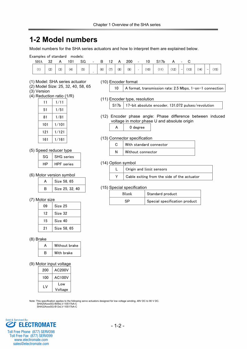
1-2 Model numbers Model numbers for the SHA series actuators and how to interpret them are explained below.
Examples of standard models: SHA 32 A 101 SG - B 12 A 200 - 10 S17b A - C
(1) (2) (3) (4) (5) -
(6) (7) (8) (9) - (10) (11) (12) - (13) (14) - (15)
(1) Model: SHA series actuator (2) Model Size: 25, 32, 40, 58, 65 (3) Version (4) Reduction ratio (1/R)
11 1/11
51 1/51
81 1/81
101 1/101
121 1/121
161 1/161
(5) Speed reducer type
SG SHG series
HP HPF series
(6) Motor version symbol
A Size 58, 65
B Size 25, 32, 40
(7) Motor size
09 Size 25
12 Size 32
15 Size 40
21 Size 58, 65
(8) Brake
A Without brake
B With brake
(9) Motor input voltage
200 AC200V
100 AC100V
LV Low
Voltage
Note: This specification applies to the following servo actuators designed for low voltage winding, 48V DC to 90 V DC. SHA25AxxxSG-B09xLV-10S17bA-C SHA32AxxxSG-B12xLV-10S17bA-C
(10) Encoder format 10 A format, transmission rate: 2.5 Mbps, 1-on-1 connection
(11) Encoder type, resolution
S17b 17-bit absolute encoder, 131,072 pulses/revolution
(12) Encoder phase angle: Phase difference between induced
voltage in motor phase U and absolute origin A 0 degree
(13) Connector specification
C With standard connector
N Without connector
(14) Option symbol
L Origin and limit sensors
Y Cable exiting from the side of the actuator
(15) Special specification
Blank Standard product
SP Special specification product
ELECTROMATEToll Free Phone (877) SERVO98
Toll Free Fax (877) SERV099www.electromate.com
Sold & Serviced By:
Chapter 1 Overview of the SHA series
- 1-3 -
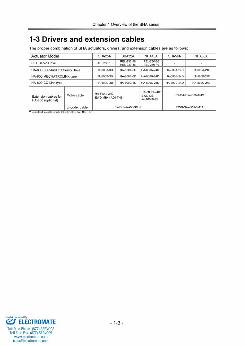
1-3 Drivers and extension cables
The proper combination of SHA actuators, drivers, and extension cables are as follows:
Actuator Model SHA25A SHA32A SHA40A SHA58A SHA65A
REL Servo Drive REL-230-18 REL-230-18 REL-230-36
REL-230-36 REL-230-40 - -
HA-800 Standard I/O Servo Drive HA-800A-3D HA-800A-6D HA-800A-24D HA-800A-24D HA-800A-24D
HA-800 MECHATROLINK type HA-800B-3D HA-800B-6D HA-800B-24D HA-800B-24D HA-800B-24D
HA-800 CC-Link type HA-800C-3D HA-800C-6D HA-800C-24D HA-800C-24D HA-800C-24D
Extension cables for HA-800 (optional)
Motor cable HA-800□-24D: EWD-MB**-A06-TN3
HA-800□-24D: EWD-MB **-A06-TMC
EWD-MB**-D09-TMC
Encoder cable EWD-S**-A08-3M14 EWD-S**-D10-3M14 ** indicates the cable length: 03 = 3m, 05 = 5m, 10 = 10m
ELECTROMATEToll Free Phone (877) SERVO98
Toll Free Fax (877) SERV099www.electromate.com
Sold & Serviced By:
Chapter 1 Overview of the SHA series
- 1-4 -
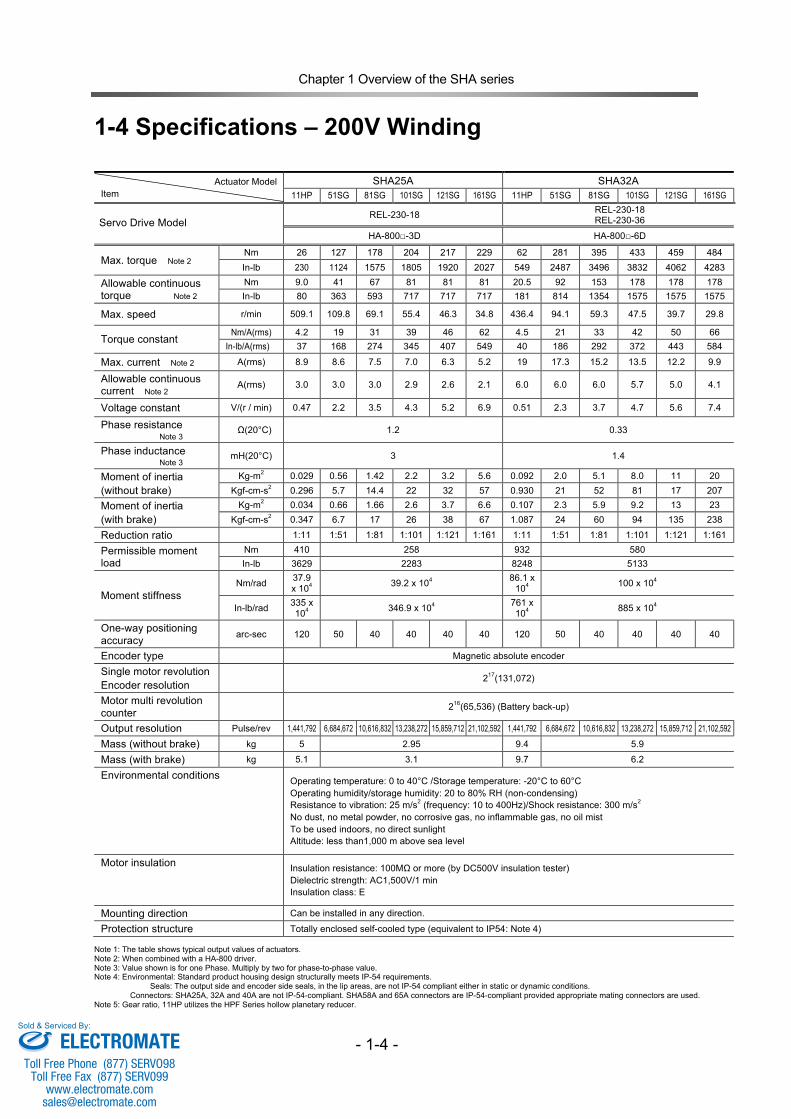
1-4 Specifications – 200V Winding
Actuator Model Item
SHA25A SHA32A 11HP 51SG 81SG 101SG 121SG 161SG 11HP 51SG 81SG 101SG 121SG 161SG
Servo Drive Model
REL-230-18 REL-230-18 REL-230-36
HA-800□-3D HA-800□-6D
Max. torque Note 2 Nm 26 127 178 204 217 229 62 281 395 433 459 484 In-lb 230 1124 1575 1805 1920 2027 549 2487 3496 3832 4062 4283
Allowable continuous torque Note 2
Nm 9.0 41 67 81 81 81 20.5 92 153 178 178 178 In-lb 80 363 593 717 717 717 181 814 1354 1575 1575 1575
Max. speed r/min 509.1 109.8 69.1 55.4 46.3 34.8 436.4 94.1 59.3 47.5 39.7 29.8
Torque constant Nm/A(rms) 4.2 19 31 39 46 62 4.5 21 33 42 50 66
In-lb/A(rms) 37 168 274 345 407 549 40 186 292 372 443 584
Max. current Note 2 A(rms) 8.9 8.6 7.5 7.0 6.3 5.2 19 17.3 15.2 13.5 12.2 9.9
Allowable continuous current Note 2 A(rms) 3.0 3.0 3.0 2.9 2.6 2.1 6.0 6.0 6.0 5.7 5.0 4.1
Voltage constant V/(r / min) 0.47 2.2 3.5 4.3 5.2 6.9 0.51 2.3 3.7 4.7 5.6 7.4
Phase resistance Note 3 Ω(20°C) 1.2 0.33
Phase inductance Note 3 mH(20°C) 3 1.4
Moment of inertia (without brake)
Kg-m2 0.029 0.56 1.42 2.2 3.2 5.6 0.092 2.0 5.1 8.0 11 20 Kgf-cm-s2 0.296 5.7 14.4 22 32 57 0.930 21 52 81 17 207
Moment of inertia (with brake)
Kg-m2 0.034 0.66 1.66 2.6 3.7 6.6 0.107 2.3 5.9 9.2 13 23 Kgf-cm-s2 0.347 6.7 17 26 38 67 1.087 24 60 94 135 238
Reduction ratio 1:11 1:51 1:81 1:101 1:121 1:161 1:11 1:51 1:81 1:101 1:121 1:161
Permissible moment load
Nm 410 258 932 580 In-lb 3629 2283 8248 5133
Moment stiffness Nm/rad 37.9
x 104 39.2 x 10⁴ 86.1 x 10⁴ 100 x 104
In-lb/rad 335 x 104 346.9 x 10⁴ 761 x
104 885 x 104
One-way positioning accuracy arc-sec 120 50 40 40 40 40 120 50 40 40 40 40
Encoder type Magnetic absolute encoder
Single motor revolution Encoder resolution
217(131,072)
Motor multi revolution counter 216(65,536) (Battery back-up)
Output resolution Pulse/rev 1,441,792 6,684,672 10,616,832 13,238,272 15,859,712 21,102,592 1,441,792 6,684,672 10,616,832 13,238,272 15,859,712 21,102,592
Mass (without brake) kg 5 2.95 9.4 5.9
Mass (with brake) kg 5.1 3.1 9.7 6.2
Environmental conditions Operating temperature: 0 to 40°C /Storage temperature: -20°C to 60°C Operating humidity/storage humidity: 20 to 80% RH (non-condensing) Resistance to vibration: 25 m/s2 (frequency: 10 to 400Hz)/Shock resistance: 300 m/s2 No dust, no metal powder, no corrosive gas, no inflammable gas, no oil mist To be used indoors, no direct sunlight Altitude: less than1,000 m above sea level
Motor insulation Insulation resistance: 100MΩ or more (by DC500V insulation tester) Dielectric strength: AC1,500V/1 min Insulation class: E
Mounting direction Can be installed in any direction.
Protection structure Totally enclosed self-cooled type (equivalent to IP54: Note 4)
Note 1: The table shows typical output values of actuators. Note 2: When combined with a HA-800 driver. Note 3: Value shown is for one Phase. Multiply by two for phase-to-phase value. Note 4: Environmental: Standard product housing design structurally meets IP-54 requirements. Seals: The output side and encoder side seals, in the lip areas, are not IP-54 compliant either in static or dynamic conditions. Connectors: SHA25A, 32A and 40A are not IP-54-compliant. SHA58A and 65A connectors are IP-54-compliant provided appropriate mating connectors are used. Note 5: Gear ratio, 11HP utilizes the HPF Series hollow planetary reducer.
ELECTROMATEToll Free Phone (877) SERVO98
Toll Free Fax (877) SERV099www.electromate.com
Sold & Serviced By:
Chapter 1 Overview of the SHA series
- 1-5 -
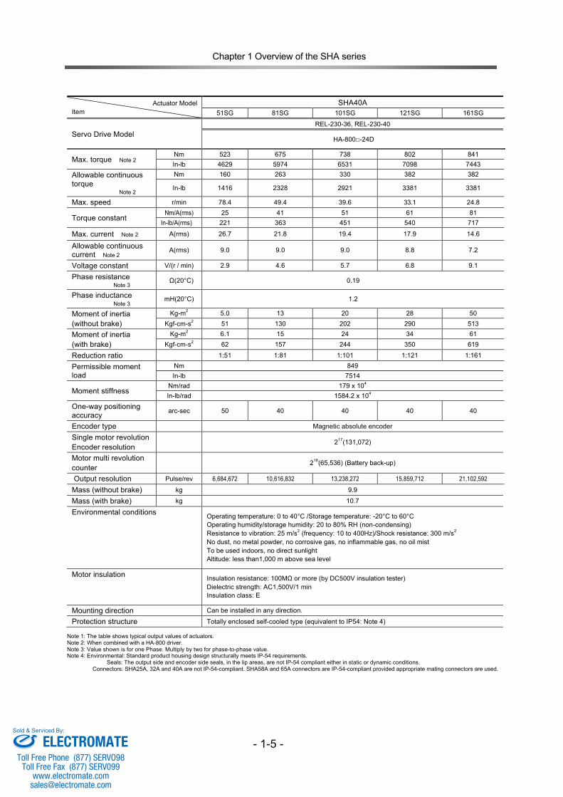
Actuator Model Item
SHA40A 51SG 81SG 101SG 121SG 161SG
Servo Drive Model
REL-230-36, REL-230-40
HA-800□-24D
Max. torque Note 2 Nm 523 675 738 802 841 In-lb 4629 5974 6531 7098 7443
Allowable continuous torque Note 2
Nm 160 263 330 382 382
In-lb 1416 2328 2921 3381 3381
Max. speed r/min 78.4 49.4 39.6 33.1 24.8
Torque constant Nm/A(rms) 25 41 51 61 81
In-lb/A(rms) 221 363 451 540 717
Max. current Note 2 A(rms) 26.7 21.8 19.4 17.9 14.6
Allowable continuous current Note 2 A(rms) 9.0 9.0 9.0 8.8 7.2
Voltage constant V/(r / min) 2.9 4.6 5.7 6.8 9.1
Phase resistance Note 3 Ω(20°C) 0.19
Phase inductance Note 3 mH(20°C) 1.2
Moment of inertia (without brake)
Kg-m2 5.0 13 20 28 50 Kgf-cm-s2 51 130 202 290 513
Moment of inertia (with brake)
Kg-m2 6.1 15 24 34 61 Kgf-cm-s2 62 157 244 350 619
Reduction ratio 1:51 1:81 1:101 1:121 1:161
Permissible moment load
Nm 849 In-lb 7514
Moment stiffness Nm/rad 179 x 104 In-lb/rad 1584.2 x 104
One-way positioning accuracy arc-sec 50 40 40 40 40
Encoder type Magnetic absolute encoder
Single motor revolution Encoder resolution
217(131,072)
Motor multi revolution counter
216(65,536) (Battery back-up)
Output resolution Pulse/rev 6,684,672 10,616,832 13,238,272 15,859,712 21,102,592
Mass (without brake) kg 9.9
Mass (with brake) kg 10.7
Environmental conditions Operating temperature: 0 to 40°C /Storage temperature: -20°C to 60°C Operating humidity/storage humidity: 20 to 80% RH (non-condensing) Resistance to vibration: 25 m/s2 (frequency: 10 to 400Hz)/Shock resistance: 300 m/s2 No dust, no metal powder, no corrosive gas, no inflammable gas, no oil mist To be used indoors, no direct sunlight Altitude: less than1,000 m above sea level
Motor insulation Insulation resistance: 100MΩ or more (by DC500V insulation tester) Dielectric strength: AC1,500V/1 min Insulation class: E
Mounting direction Can be installed in any direction.
Protection structure Totally enclosed self-cooled type (equivalent to IP54: Note 4)
Note 1: The table shows typical output values of actuators. Note 2: When combined with a HA-800 driver. Note 3: Value shown is for one Phase. Multiply by two for phase-to-phase value. Note 4: Environmental: Standard product housing design structurally meets IP-54 requirements. Seals: The output side and encoder side seals, in the lip areas, are not IP-54 compliant either in static or dynamic conditions. Connectors: SHA25A, 32A and 40A are not IP-54-compliant. SHA58A and 65A connectors are IP-54-compliant provided appropriate mating connectors are used.
ELECTROMATEToll Free Phone (877) SERVO98
Toll Free Fax (877) SERV099www.electromate.com
Sold & Serviced By:
Chapter 1 Overview of the SHA series
- 1-6 -
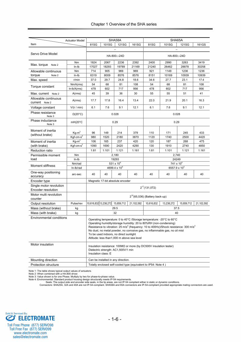
Actuator Model Item
SHA58A SHA65A 81SG 101SG 121SG 161SG 81SG 101SG 121SG 161GS
Servo Drive Model
– –
HA-800□-24D HA-800□-24D
Max. torque Note 2 Nm 1924 2067 2236 2392 2400 2990 3263 3419 In-lb 17027 18293 19789 21169 21240 26462 28878 30258
Allowable continuous torque Note 2
Nm 714 905 969 969 921 1149 1236 1236 In-lb 6319 8009 8576 8576 8151 10169 10939 10939
Max. speed r/min 37.0 29.7 24.8 18.6 34.6 27.7 23.1 17.4
Torque constant Nm/A(rms) 54 68 81 108 54 68 81 108
In-lb/A(rms) 478 602 717 956 478 602 717 956
Max. current Note 2 A(rms) 45 39 36 30 55 55 51 41
Allowable continuous current Note 2 A(rms) 17.7 17.8 16.4 13.4 22.0 21.9 20.1 16.3
Voltage constant V/(r / min) 6.1 7.6 9.1 12.1 6.1 7.6 9.1 12.1
Phase resistance Note 3 Ω(20°C) 0.028 0.028
Phase inductance Note 3 mH(20°C 0.29 0.29
Moment of inertia (without brake)
Kg-m2 96 149 214 379 110 171 245 433 Kgf-cm-s2 980 1520 2180 3870 1120 1740 2500 4420
Moment of inertia (with brake)
Kg-m2 106 165 237 420 120 187 268 475 Kgf-cm-s2 1090 1690 2420 4290 130 1910 2740 4850
Reduction ratio 1:81 1:101 1:121 1:161 1:81 1:101 1:121 1:161
Permissible moment load
Nm 2,180 2,740 In-lb 19293 24249
Moment stiffness Nm/rad 531 x 104 741 x 104 In-lb/rad 4699.4 x 104 6557.9 x 104
One-way positioning accuracy arc-sec 40 40 40 40 40 40 40 40
Encoder type Magnetic 17-bit absolute encoder
Single motor revolution Encoder resolution 217(131,072)
Motor multi revolution counter 216(65,536) (Battery back-up)
Output resolution Pulse/rev 10,616,832 13,238,272 15,859,712 21,102,592 10,616,832 13,238,272 15,859,712 21,102,592
Mass (without brake) kg 29.5 37.5
Mass (with brake) kg 32 40
Environmental conditions Operating temperature: 0 to 40°C /Storage temperature: -20°C to 60°C Operating humidity/storage humidity: 20 to 80%RH (non-condensing) Resistance to vibration: 25 m/s2 (frequency: 10 to 400Hz)/Shock resistance: 300 m/s2 No dust, no metal powder, no corrosive gas, no inflammable gas, no oil mist To be used indoors, no direct sunlight Altitude: less than1,000 m above sea level
Motor insulation Insulation resistance: 100MΩ or more (by DC500V insulation tester) Dielectric strength: AC1,500V/1 min Insulation class: E
Mounting direction Can be installed in any direction.
Protection structure Totally enclosed self-cooled type (equivalent to IP54: Note 4 )
Note 1: The table shows typical output values of actuators. Note 2: When combined with a HA-800 driver. Note 3: Value shown is for one Phase. Multiply by two for phase-to-phase value. Note 4: Environmental: Standard product housing design structurally meets IP-54 requirements. Seals: The output side and encoder side seals, in the lip areas, are not IP-54 compliant either in static or dynamic conditions. Connectors: SHA25A, 32A and 40A are not IP-54-compliant. SHA58A and 65A connectors are IP-54-compliant provided appropriate mating connectors are used.
ELECTROMATEToll Free Phone (877) SERVO98
Toll Free Fax (877) SERV099www.electromate.com
Sold & Serviced By:
Chapter 1 Overview of the SHA series
- 1-7 -
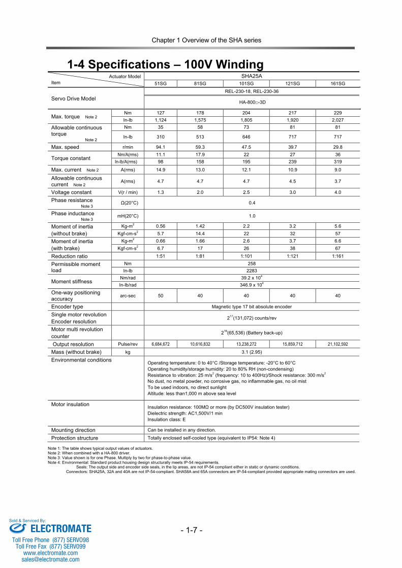
1-4 Specifications – 100V Winding
Actuator Model Item
SHA25A 51SG 81SG 101SG 121SG 161SG
Servo Drive Model
REL-230-18, REL-230-36
HA-800□-3D
Max. torque Note 2 Nm 127 178 204 217 229 In-lb 1,124 1,575 1,805 1,920 2,027
Allowable continuous torque Note 2
Nm 35 58 73 81 81
In-lb 310 513 646 717 717
Max. speed r/min 94.1 59.3 47.5 39.7 29.8
Torque constant Nm/A(rms) 11.1 17.9 22 27 36
In-lb/A(rms) 98 158 195 239 319
Max. current Note 2 A(rms) 14.9 13.0 12.1 10.9 9.0
Allowable continuous current Note 2 A(rms) 4.7 4.7 4.7 4.5 3.7
Voltage constant V(r / min) 1.3 2.0 2.5 3.0 4.0
Phase resistance Note 3 Ω(20°C) 0.4
Phase inductance Note 3 mH(20°C) 1.0
Moment of inertia (without brake)
Kg-m2 0.56 1.42 2.2 3.2 5.6 Kgf-cm-s2 5.7 14.4 22 32 57
Moment of inertia (with brake)
Kg-m2 0.66 1.66 2.6 3.7 6.6 Kgf-cm-s2 6.7 17 26 38 67
Reduction ratio 1:51 1:81 1:101 1:121 1:161
Permissible moment load
Nm 258 In-lb 2283
Moment stiffness Nm/rad 39.2 x 10⁴ In-lb/rad 346.9 x 10⁴
One-way positioning accuracy arc-sec 50 40 40 40 40
Encoder type Magnetic type 17 bit absolute encoder
Single motor revolution Encoder resolution
217(131,072) counts/rev
Motor multi revolution counter 216(65,536) (Battery back-up)
Output resolution Pulse/rev 6,684,672 10,616,832 13,238,272 15,859,712 21,102,592
Mass (without brake) kg 3.1 (2.95)
Environmental conditions Operating temperature: 0 to 40°C /Storage temperature: -20°C to 60°C Operating humidity/storage humidity: 20 to 80% RH (non-condensing) Resistance to vibration: 25 m/s2 (frequency: 10 to 400Hz)/Shock resistance: 300 m/s2 No dust, no metal powder, no corrosive gas, no inflammable gas, no oil mist To be used indoors, no direct sunlight Altitude: less than1,000 m above sea level
Motor insulation Insulation resistance: 100MΩ or more (by DC500V insulation tester) Dielectric strength: AC1,500V/1 min Insulation class: E
Mounting direction Can be installed in any direction.
Protection structure Totally enclosed self-cooled type (equivalent to IP54: Note 4)
Note 1: The table shows typical output values of actuators. Note 2: When combined with a HA-800 driver. Note 3: Value shown is for one Phase. Multiply by two for phase-to-phase value. Note 4: Environmental: Standard product housing design structurally meets IP-54 requirements. Seals: The output side and encoder side seals, in the lip areas, are not IP-54 compliant either in static or dynamic conditions. Connectors: SHA25A, 32A and 40A are not IP-54-compliant. SHA58A and 65A connectors are IP-54-compliant provided appropriate mating connectors are used.
ELECTROMATEToll Free Phone (877) SERVO98
Toll Free Fax (877) SERV099www.electromate.com
Sold & Serviced By:
Chapter 1 Overview of the SHA series
- 1-8 -
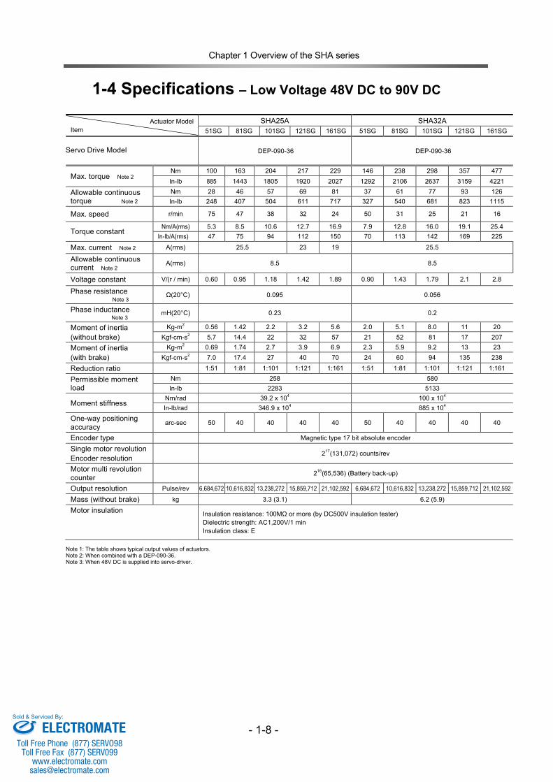
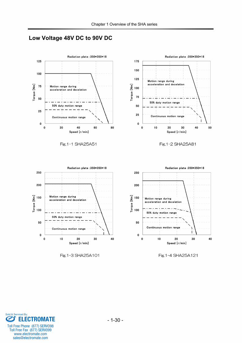
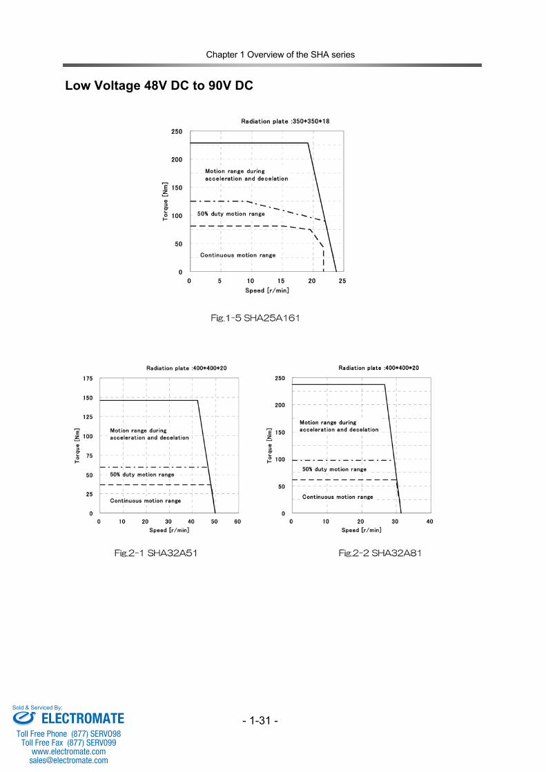
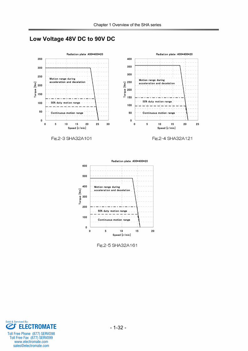
1-4 Specifications – Low Voltage 48V DC to 90V DC
Actuator Model Item
SHA25A SHA32A 51SG 81SG 101SG 121SG 161SG 51SG 81SG 101SG 121SG 161SG
Servo Drive Model
DEP-090-36 DEP-090-36
Max. torque Note 2 Nm 100 163 204 217 229 146 238 298 357 477 In-lb 885 1443 1805 1920 2027 1292 2106 2637 3159 4221
Allowable continuous torque Note 2
Nm 28 46 57 69 81 37 61 77 93 126 In-lb 248 407 504 611 717 327 540 681 823 1115
Max. speed r/min 75 47 38 32 24 50 31 25 21 16
Torque constant Nm/A(rms) 5.3 8.5 10.6 12.7 16.9 7.9 12.8 16.0 19.1 25.4
In-lb/A(rms) 47 75 94 112 150 70 113 142 169 225
Max. current Note 2 A(rms) 25.5 23 19 25.5
Allowable continuous current Note 2 A(rms) 8.5 8.5
Voltage constant V/(r / min) 0.60 0.95 1.18 1.42 1.89 0.90 1.43 1.79 2.1 2.8
Phase resistance Note 3 Ω(20°C) 0.095 0.056
Phase inductance Note 3 mH(20°C) 0.23 0.2
Moment of inertia (without brake)
Kg-m2 0.56 1.42 2.2 3.2 5.6 2.0 5.1 8.0 11 20 Kgf-cm-s2 5.7 14.4 22 32 57 21 52 81 17 207
Moment of inertia (with brake)
Kg-m2 0.69 1.74 2.7 3.9 6.9 2.3 5.9 9.2 13 23 Kgf-cm-s2 7.0 17.4 27 40 70 24 60 94 135 238
Reduction ratio 1:51 1:81 1:101 1:121 1:161 1:51 1:81 1:101 1:121 1:161
Permissible moment load
Nm 258 580 In-lb 2283 5133
Moment stiffness Nm/rad 39.2 x 10⁴ 100 x 104 In-lb/rad 346.9 x 10⁴ 885 x 104
One-way positioning accuracy arc-sec 50 40 40 40 40 50 40 40 40 40
Encoder type Magnetic type 17 bit absolute encoder
Single motor revolution Encoder resolution
217(131,072) counts/rev
Motor multi revolution counter 216(65,536) (Battery back-up)
Output resolution Pulse/rev 6,684,672 10,616,832 13,238,272 15,859,712 21,102,592 6,684,672 10,616,832 13,238,272 15,859,712 21,102,592
Mass (without brake) kg 3.3 (3.1) 6.2 (5.9)
Motor insulation Insulation resistance: 100MΩ or more (by DC500V insulation tester) Dielectric strength: AC1,200V/1 min Insulation class: E
Note 1: The table shows typical output values of actuators. Note 2: When combined with a DEP-090-36. Note 3: When 48V DC is supplied into servo-driver.
ELECTROMATEToll Free Phone (877) SERVO98
Toll Free Fax (877) SERV099www.electromate.com
Sold & Serviced By:
Chapter 1 Overview of the SHA series
- 1-9 -
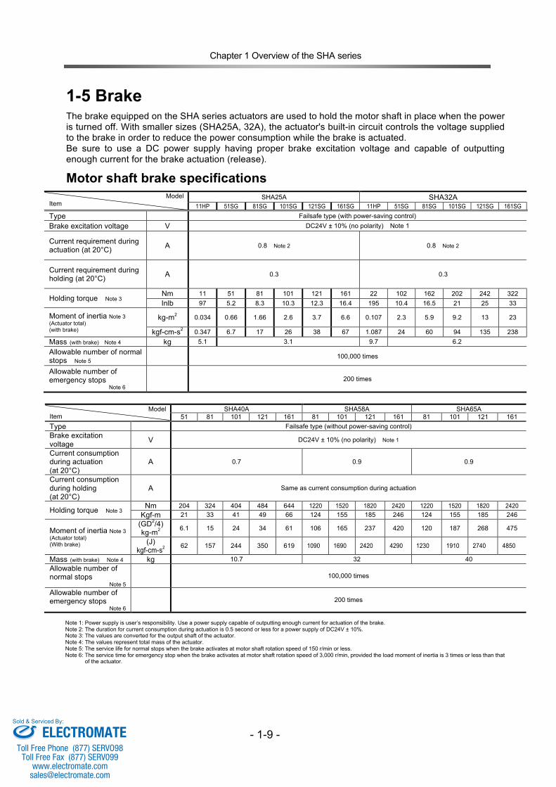
1-5 Brake The brake equipped on the SHA series actuators are used to hold the motor shaft in place when the power is turned off. With smaller sizes (SHA25A, 32A), the actuator's built-in circuit controls the voltage supplied to the brake in order to reduce the power consumption while the brake is actuated. Be sure to use a DC power supply having proper brake excitation voltage and capable of outputting enough current for the brake actuation (release).
Motor shaft brake specifications Model
Item SHA25A SHA32A
11HP 51SG 81SG 101SG 121SG 161SG 11HP 51SG 81SG 101SG 121SG 161SG Type Failsafe type (with power-saving control) Brake excitation voltage V DC24V ± 10% (no polarity) Note 1
Current requirement during actuation (at 20°C) A 0.8 Note 2 0.8 Note 2
Current requirement during holding (at 20°C) A 0.3 0.3
Holding torque Note 3 Nm 11 51 81 101 121 161 22 102 162 202 242 322 Inlb 97 5.2 8.3 10.3 12.3 16.4 195 10.4 16.5 21 25 33
Moment of inertia Note 3 (Actuator total) (with brake)
kg-m2 0.034 0.66 1.66 2.6 3.7 6.6 0.107 2.3 5.9 9.2 13 23
kgf-cm-s2 0.347 6.7 17 26 38 67 1.087 24 60 94 135 238 Mass (with brake) Note 4 kg 5.1 3.1 9.7 6.2 Allowable number of normal stops Note 5 100,000 times
Allowable number of emergency stops Note 6
200 times
Model
Item SHA40A SHA58A SHA65A
51 81 101 121 161 81 101 121 161 81 101 121 161 Type Failsafe type (without power-saving control) Brake excitation voltage V DC24V ± 10% (no polarity) Note 1
Current consumption during actuation (at 20°C)
A 0.7 0.9 0.9
Current consumption during holding (at 20°C)
A Same as current consumption during actuation
Holding torque Note 3 Nm 204 324 404 484 644 1220 1520 1820 2420 1220 1520 1820 2420 Kgf-m 21 33 41 49 66 124 155 185 246 124 155 185 246
Moment of inertia Note 3 (Actuator total) (With brake)
(GD2/4) kg-m2 6.1 15 24 34 61 106 165 237 420 120 187 268 475
(J) kgf-cm-s2 62 157 244 350 619 1090 1690 2420 4290 1230 1910 2740 4850
Mass (with brake) Note 4 kg 10.7 32 40 Allowable number of normal stops Note 5
100,000 times
Allowable number of emergency stops Note 6
200 times
Note 1: Power supply is user’s responsibility. Use a power supply capable of outputting enough current for actuation of the brake. Note 2: The duration for current consumption during actuation is 0.5 second or less for a power supply of DC24V ± 10%. Note 3: The values are converted for the output shaft of the actuator. Note 4: The values represent total mass of the actuator. Note 5: The service life for normal stops when the brake activates at motor shaft rotation speed of 150 r/min or less. Note 6: The service time for emergency stop when the brake activates at motor shaft rotation speed of 3,000 r/min, provided the load moment of inertia is 3 times or less than that
of the actuator.
ELECTROMATEToll Free Phone (877) SERVO98
Toll Free Fax (877) SERV099www.electromate.com
Sold & Serviced By:
Chapter 1 Overview of the SHA series
- 1-10 -
The motor shaft holding brake cannot be used for deceleration. Do not use the holding brake more than the allowable number of normal stops (100,000 times with the motor shaft rotation speed of 150 r/min or less) or the allowable number of emergency stops (200 times with the motor shaft rotation speed of 3,000 r/min, provided the load moment of inertia is 3 times or less than that of the actuator). Exceeding the allowable number of normal stops or allowable number of emergency stops may deteriorate the holding torque, and it may consequently fail to properly serve as a brake.
WARNING
ELECTROMATEToll Free Phone (877) SERVO98
Toll Free Fax (877) SERV099www.electromate.com
Sold & Serviced By:
Chapter 1 Overview of the SHA series
- 1-11 -
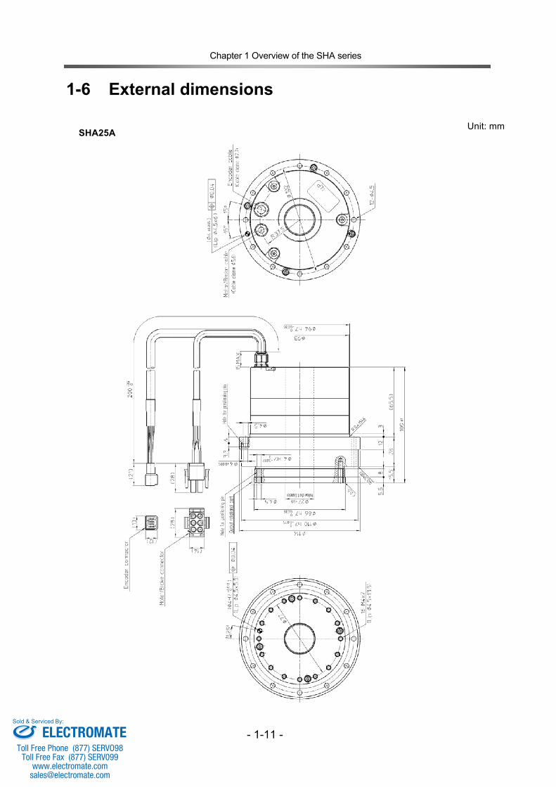
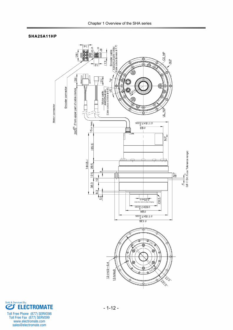
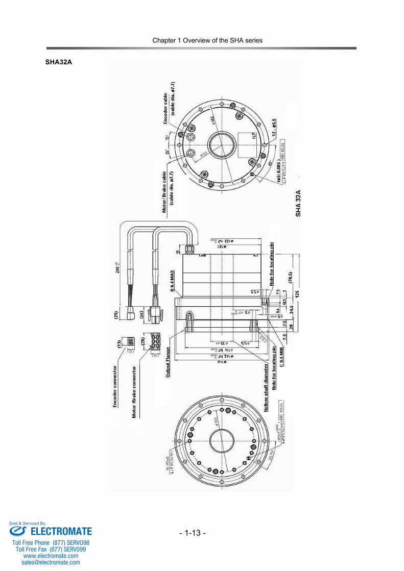
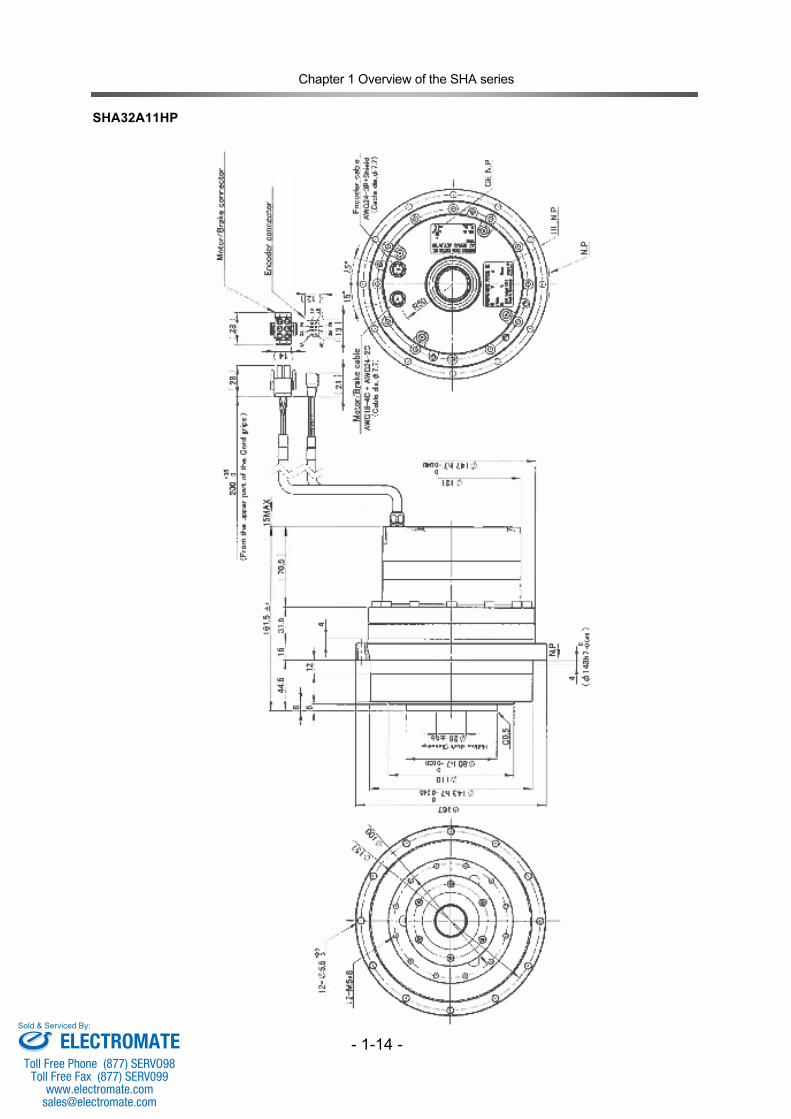
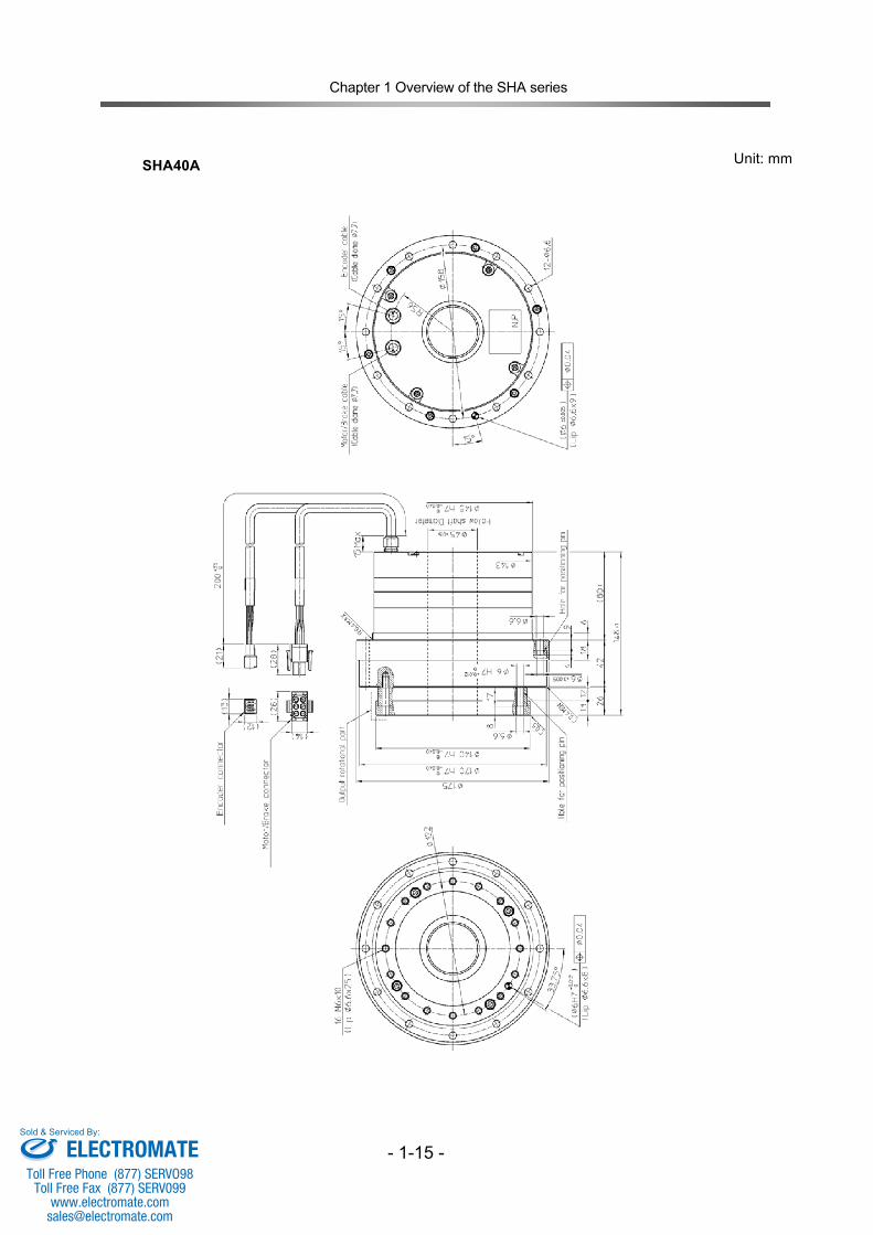
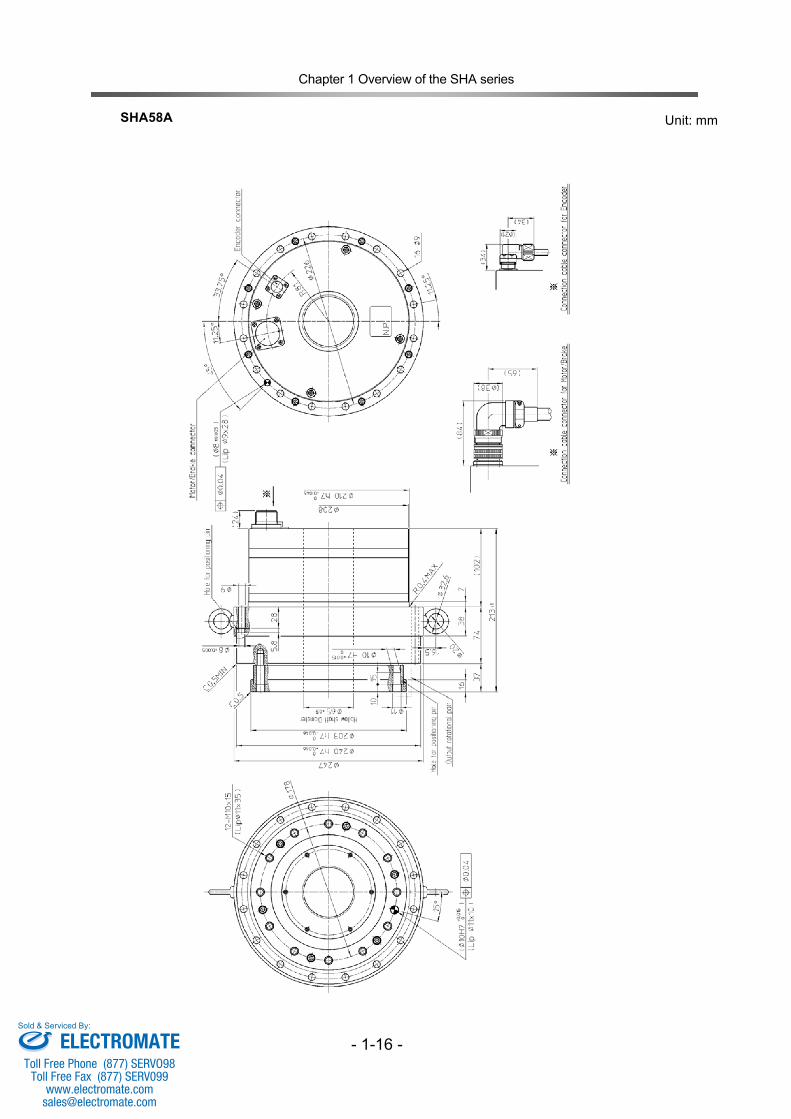
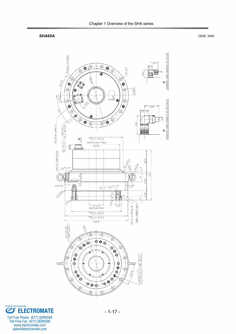
1-6 External dimensions
Unit: mm
SHA25A
ELECTROMATEToll Free Phone (877) SERVO98
Toll Free Fax (877) SERV099www.electromate.com
Sold & Serviced By:
Chapter 1 Overview of the SHA series
- 1-12 -
SHA25A11HP
ELECTROMATEToll Free Phone (877) SERVO98
Toll Free Fax (877) SERV099www.electromate.com
Sold & Serviced By:
Chapter 1 Overview of the SHA series
- 1-13 -
SHA32A
ELECTROMATEToll Free Phone (877) SERVO98
Toll Free Fax (877) SERV099www.electromate.com
Sold & Serviced By:
Chapter 1 Overview of the SHA series
- 1-14 -
SHA32A11HP
ELECTROMATEToll Free Phone (877) SERVO98
Toll Free Fax (877) SERV099www.electromate.com
Sold & Serviced By:
Chapter 1 Overview of the SHA series
- 1-15 -
Unit: mm
SHA40A
ELECTROMATEToll Free Phone (877) SERVO98
Toll Free Fax (877) SERV099www.electromate.com
Sold & Serviced By:
Chapter 1 Overview of the SHA series
- 1-16 -
Unit: mm
SHA58A
ELECTROMATEToll Free Phone (877) SERVO98
Toll Free Fax (877) SERV099www.electromate.com
Sold & Serviced By:
Chapter 1 Overview of the SHA series
- 1-17 -
Unit: mm
SHA65A
ELECTROMATEToll Free Phone (877) SERVO98
Toll Free Fax (877) SERV099www.electromate.com
Sold & Serviced By:
Chapter 1 Overview of the SHA series
- 1-18 -
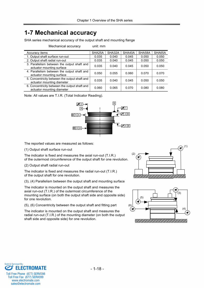
1-7 Mechanical accuracy SHA series mechanical accuracy of the output shaft and mounting flange
Mechanical accuracy unit: mm
Accuracy items SHA25A SHA32A SHA40A SHA58A SHA65A 1. Output shaft surface run-out 0.035 0.040 0.045 0.050 0.050 2. Output shaft radial run-out 0.035 0.040 0.045 0.050 0.050 3. Parallelism between the output shaft and
actuator mounting surface 0.035 0.040 0.045 0.050 0.050
4. Parallelism between the output shaft and actuator mounting surface 0.050 0.055 0.060 0.070 0.070
5. Concentricity between the output shaft and actuator mounting diameter 0.035 0.040 0.045 0.050 0.050
6. Concentricity between the output shaft and actuator mounting diameter 0.060 0.065 0.070 0.080 0.080
Note: All values are T.I.R. (Total Indicator Reading).
The reported values are measured as follows:
(1) Output shaft surface run-out
The indicator is fixed and measures the axial run-out (T.I.R.) of the outermost circumference of the output shaft for one revolution.
(2) Output shaft radial run-out
The indicator is fixed and measures the radial run-out (T.I.R.) of the output shaft for one revolution.
(3), (4) Parallelism between the output shaft and mounting surface
The indicator is mounted on the output shaft and measures the axial run-out (T.I.R.) of the outermost circumference of the mounting surface (on both the output shaft side and opposite side) for one revolution.
(5), (6) Concentricity between the output shaft and fitting part
The indicator is mounted on the output shaft and measures the radial run-out (T.I.R.) of the mounting diameter (on both the output shaft side and opposite side) for one revolution.
A 5 ◎
2
A B
1
A 6 ◎
3 B
4 B
(1)
(2)
(3)
(5)
(6)
(4)
ELECTROMATEToll Free Phone (877) SERVO98
Toll Free Fax (877) SERV099www.electromate.com
Sold & Serviced By:
Chapter 1 Overview of the SHA series
- 1-19 -
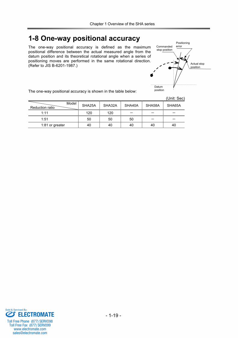
1-8 One-way positional accuracy The one-way positional accuracy is defined as the maximum positional difference between the actual measured angle from the datum position and its theoretical rotational angle when a series of positioning moves are performed in the same rotational direction. (Refer to JIS B-6201-1987.)
The one-way positional accuracy is shown in the table below:
(Unit: Sec) Model
Reduction ratio SHA25A SHA32A SHA40A SHA58A SHA65A
1:11 120 120 ‐ ‐ ‐
1:51 50 50 50 ‐ ‐
1:81 or greater 40 40 40 40 40
Datum position
Actual stop position
Commanded stop position
Positioning error
ELECTROMATEToll Free Phone (877) SERVO98
Toll Free Fax (877) SERV099www.electromate.com
Sold & Serviced By:
Chapter 1 Overview of the SHA series
- 1-20 -
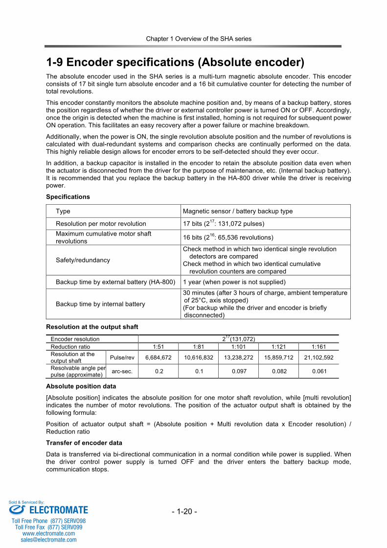
1-9 Encoder specifications (Absolute encoder) The absolute encoder used in the SHA series is a multi-turn magnetic absolute encoder. This encoder consists of 17 bit single turn absolute encoder and a 16 bit cumulative counter for detecting the number of total revolutions.
This encoder constantly monitors the absolute machine position and, by means of a backup battery, stores the position regardless of whether the driver or external controller power is turned ON or OFF. Accordingly, once the origin is detected when the machine is first installed, homing is not required for subsequent power ON operation. This facilitates an easy recovery after a power failure or machine breakdown.
Additionally, when the power is ON, the single revolution absolute position and the number of revolutions is calculated with dual-redundant systems and comparison checks are continually performed on the data. This highly reliable design allows for encoder errors to be self-detected should they ever occur.
In addition, a backup capacitor is installed in the encoder to retain the absolute position data even when the actuator is disconnected from the driver for the purpose of maintenance, etc. (Internal backup battery). It is recommended that you replace the backup battery in the HA-800 driver while the driver is receiving power.
Specifications
Type Magnetic sensor / battery backup type
Resolution per motor revolution 17 bits (217: 131,072 pulses) Maximum cumulative motor shaft
revolutions 16 bits (216: 65,536 revolutions)
Safety/redundancy
Check method in which two identical single revolution detectors are compared
Check method in which two identical cumulative revolution counters are compared
Backup time by external battery (HA-800) 1 year (when power is not supplied)
Backup time by internal battery
30 minutes (after 3 hours of charge, ambient temperature of 25°C, axis stopped) (For backup while the driver and encoder is briefly disconnected)
Resolution at the output shaft
Encoder resolution 217(131,072) Reduction ratio 1:51 1:81 1:101 1:121 1:161 Resolution at the output shaft Pulse/rev 6,684,672 10,616,832 13,238,272 15,859,712 21,102,592
Resolvable angle per pulse (approximate) arc-sec. 0.2 0.1 0.097 0.082 0.061
Absolute position data
[Absolute position] indicates the absolute position for one motor shaft revolution, while [multi revolution] indicates the number of motor revolutions. The position of the actuator output shaft is obtained by the following formula:
Position of actuator output shaft = (Absolute position + Multi revolution data x Encoder resolution) / Reduction ratio
Transfer of encoder data
Data is transferred via bi-directional communication in a normal condition while power is supplied. When the driver control power supply is turned OFF and the driver enters the battery backup mode, communication stops.
ELECTROMATEToll Free Phone (877) SERVO98
Toll Free Fax (877) SERV099www.electromate.com
Sold & Serviced By:
Chapter 1 Overview of the SHA series
- 1-21 -
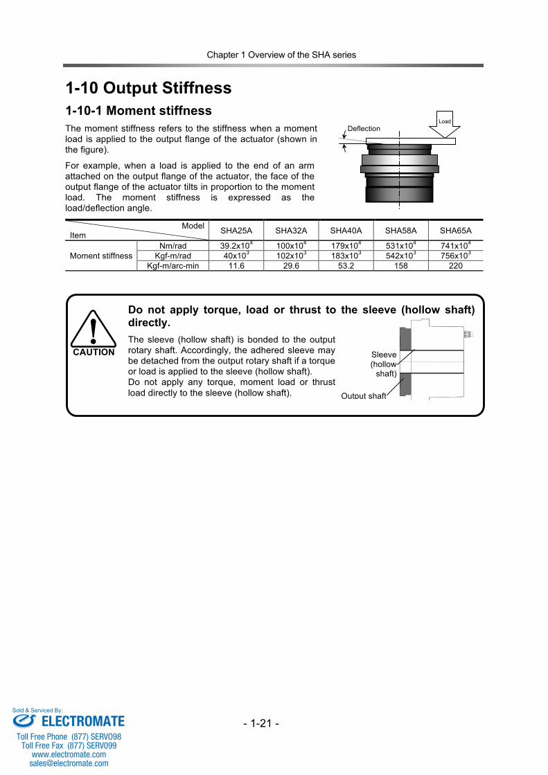
1-10 Output Stiffness 1-10-1 Moment stiffness The moment stiffness refers to the stiffness when a moment load is applied to the output flange of the actuator (shown in the figure).
For example, when a load is applied to the end of an arm attached on the output flange of the actuator, the face of the output flange of the actuator tilts in proportion to the moment load. The moment stiffness is expressed as the load/deflection angle.
Model Item SHA25A SHA32A SHA40A SHA58A SHA65A
Moment stiffness Nm/rad 39.2x10⁴ 100x104 179x104 531x104 741x104
Kgf-m/rad 40x103 102x103 183x103 542x103 756x103 Kgf-m/arc-min 11.6 29.6 53.2 158 220
Do not apply torque, load or thrust to the sleeve (hollow shaft) directly. The sleeve (hollow shaft) is bonded to the output rotary shaft. Accordingly, the adhered sleeve may be detached from the output rotary shaft if a torque or load is applied to the sleeve (hollow shaft). Do not apply any torque, moment load or thrust load directly to the sleeve (hollow shaft).
CAUTION
Load
Deflection
Sleeve (hollow
shaft)
Output shaft
ELECTROMATEToll Free Phone (877) SERVO98
Toll Free Fax (877) SERV099www.electromate.com
Sold & Serviced By:
Chapter 1 Overview of the SHA series
- 1-22 -
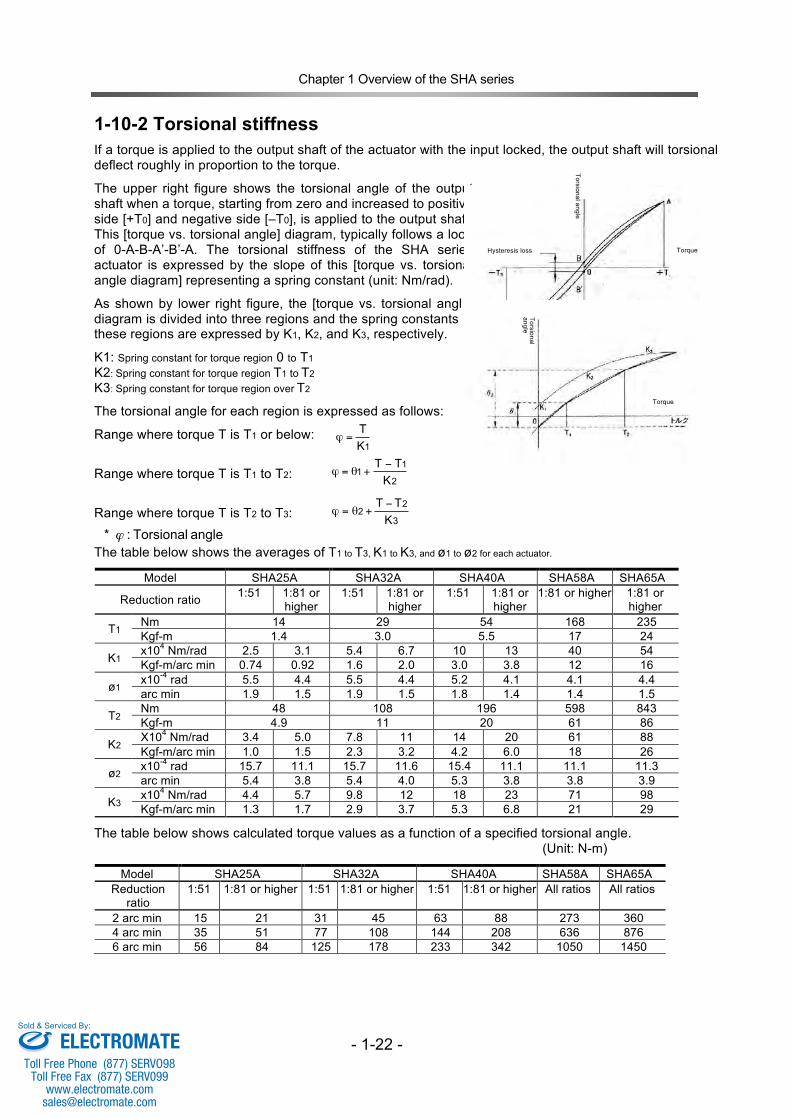
1-10-2 Torsional stiffness If a torque is applied to the output shaft of the actuator with the input locked, the output shaft will torsional deflect roughly in proportion to the torque.
The upper right figure shows the torsional angle of the output shaft when a torque, starting from zero and increased to positive side [+T0] and negative side [–T0], is applied to the output shaft. This [torque vs. torsional angle] diagram, typically follows a loop of 0-A-B-A’-B’-A. The torsional stiffness of the SHA series actuator is expressed by the slope of this [torque vs. torsional angle diagram] representing a spring constant (unit: Nm/rad).
As shown by lower right figure, the [torque vs. torsional angle] diagram is divided into three regions and the spring constants in these regions are expressed by K1, K2, and K3, respectively.
K1: Spring constant for torque region 0 to T1 K2: Spring constant for torque region T1 to T2 K3: Spring constant for torque region over T2
The torsional angle for each region is expressed as follows:
Range where torque T is T1 or below:
Range where torque T is T1 to T2:
Range where torque T is T2 to T3:
The table below shows the averages of T1 to T3, K1 to K3, and ø1 to ø2 for each actuator.
Model SHA25A SHA32A SHA40A SHA58A SHA65A
Reduction ratio 1:51 1:81 or higher
1:51 1:81 or higher
1:51 1:81 or higher
1:81 or higher 1:81 or higher
T1 Nm 14 29 54 168 235 Kgf-m 1.4 3.0 5.5 17 24
K1 x104 Nm/rad 2.5 3.1 5.4 6.7 10 13 40 54 Kgf-m/arc min 0.74 0.92 1.6 2.0 3.0 3.8 12 16
ø1 x10⁻⁴ rad 5.5 4.4 5.5 4.4 5.2 4.1 4.1 4.4 arc min 1.9 1.5 1.9 1.5 1.8 1.4 1.4 1.5
T2 Nm 48 108 196 598 843 Kgf-m 4.9 11 20 61 86
K2 X104 Nm/rad 3.4 5.0 7.8 11 14 20 61 88 Kgf-m/arc min 1.0 1.5 2.3 3.2 4.2 6.0 18 26
ø2 x10⁻⁴ rad 15.7 11.1 15.7 11.6 15.4 11.1 11.1 11.3 arc min 5.4 3.8 5.4 4.0 5.3 3.8 3.8 3.9
K3 x104 Nm/rad 4.4 5.7 9.8 12 18 23 71 98 Kgf-m/arc min 1.3 1.7 2.9 3.7 5.3 6.8 21 29
The table below shows calculated torque values as a function of a specified torsional angle. (Unit: N-m)
Model SHA25A SHA32A SHA40A SHA58A SHA65A Reduction
ratio 1:51 1:81 or higher 1:51 1:81 or higher 1:51 1:81 or higher All ratios All ratios
2 arc min 15 21 31 45 63 88 273 360 4 arc min 35 51 77 108 144 208 636 876 6 arc min 56 84 125 178 233 342 1050 1450
3
22
K
TT !+"=#
2
11
K
TT !+"=#
Torsional angle
Torsional angle
1K
T=!
angle Torsional: * !
Hysteresis loss Torque
Torque
ELECTROMATEToll Free Phone (877) SERVO98
Toll Free Fax (877) SERV099www.electromate.com
Sold & Serviced By:
Chapter 1 Overview of the SHA series
- 1-23 -
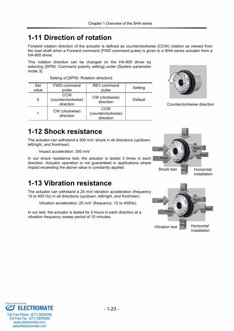
1-11 Direction of rotation Forward rotation direction of the actuator is defined as counterclockwise (CCW) rotation as viewed from the load shaft when a Forward command (FWD command pulse) is given to a SHA series actuator from a HA-800 driver.
This rotation direction can be changed on the HA-800 driver by selecting [SP50: Command polarity setting] under [System parameter mode 3].
Setting of [SP50: Rotation direction]
Set value
FWD command pulse
REV command pulse Setting
0 CCW
(counterclockwise) direction
CW (clockwise) direction
Default
1 CW (clockwise) direction
CCW (counterclockwise)
direction
1-12 Shock resistance The actuator can withstand a 300 m/s2 shock in all directions (up/down, left/right, and front/rear):
Impact acceleration: 300 m/s2
In our shock resistance test, the actuator is tested 3 times in each direction. Actuator operation is not guaranteed in applications where impact exceeding the above value is constantly applied.
1-13 Vibration resistance The actuator can withstand a 25 m/s2 vibration acceleration (frequency 10 to 400 Hz) in all directions (up/down, left/right, and front/rear):
Vibration acceleration: 25 m/s2 (frequency: 10 to 400Hz)
In our test, the actuator is tested for 2 hours in each direction at a vibration frequency sweep period of 10 minutes.
Shock test Horizontal installation
Right Left
Up
Down
Rear
Vibration test Horizontal installation
Up
Down
Front
Rear Front
Counterclockwise direction
Right Left
ELECTROMATEToll Free Phone (877) SERVO98
Toll Free Fax (877) SERV099www.electromate.com
Sold & Serviced By:
Chapter 1 Overview of the SHA series
- 1-24 -
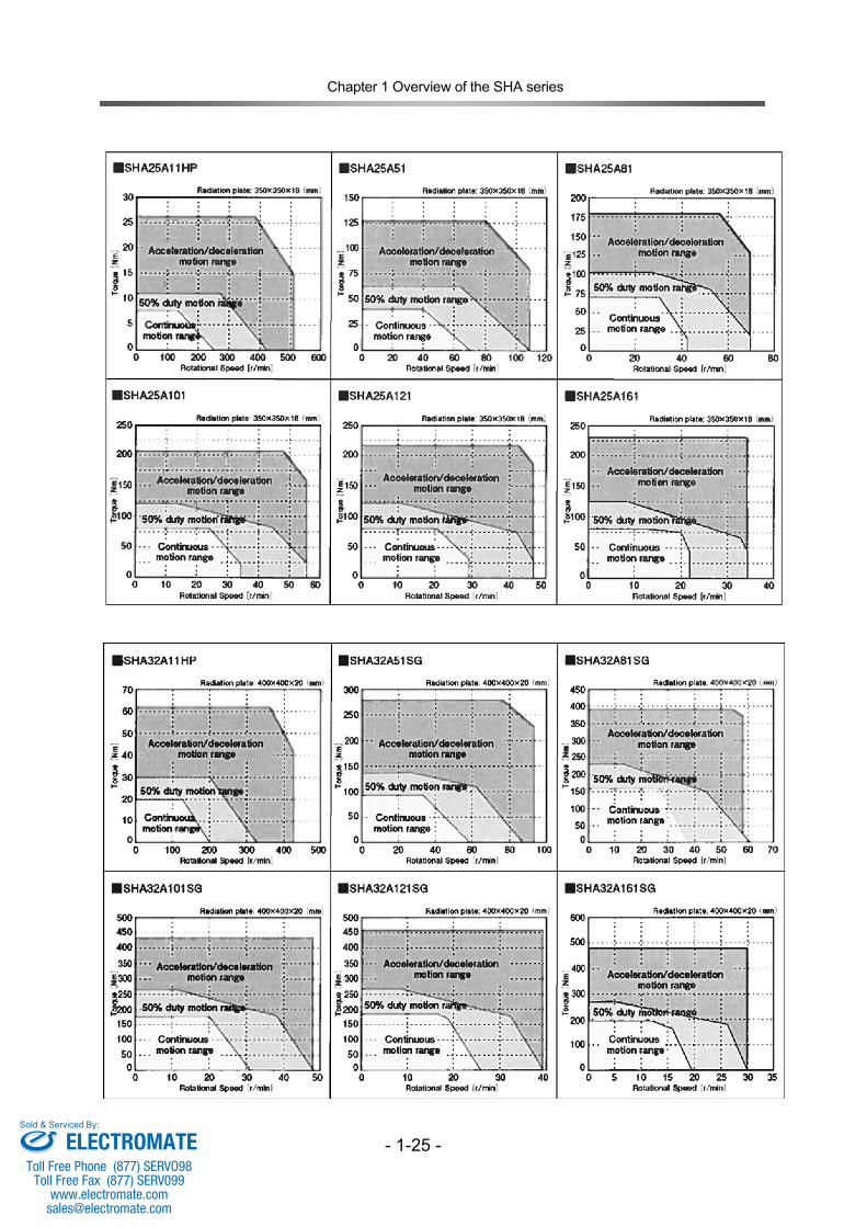
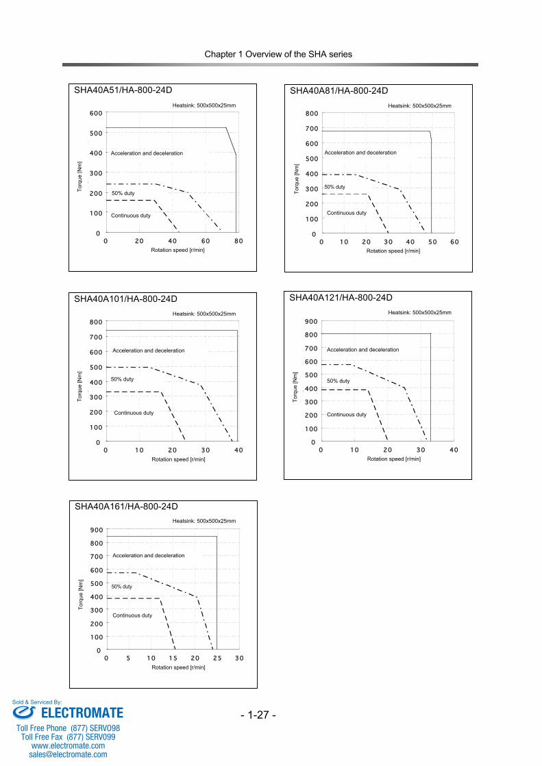
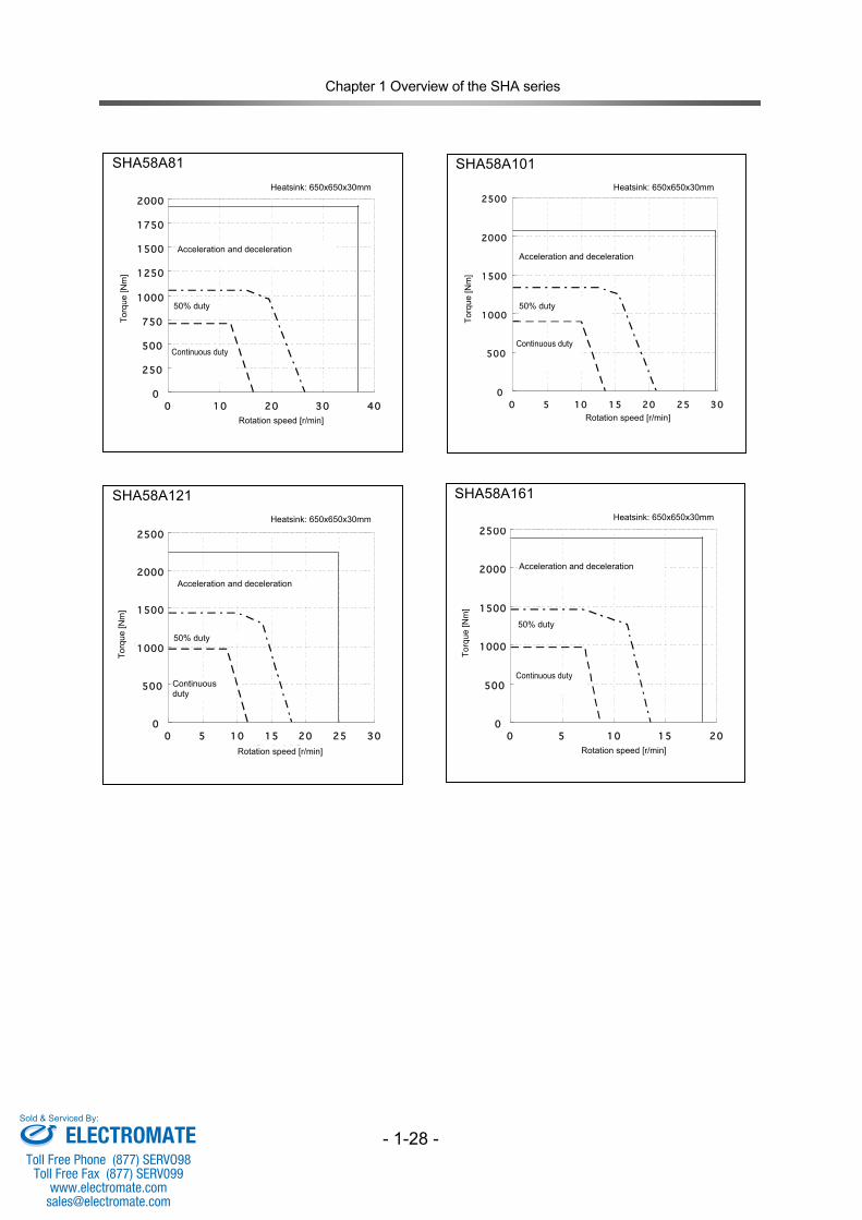
1-14 Torque / Speed operating range The graphs on the next page indicate the torque/speed operating range for the SHA actuators (when used with the HA-800 driver). For details on driver selection, refer to [Chapter 2 SHA series selection].
(1) Continuous duty range
The range allows continuous operation of the actuator.
(2) 50% duty range
This range indicates the torque/speed where 50% duty cycle operation is permitted (the ratio of operating time and idle time is 50:50).
(3) Acceleration and deceleration range
This range indicates the torque/speed which the actuator can be operated momentarily. The range allows instantaneous operation like acceleration and deceleration. The continuous and 50% duty motion ranges in each graph are measured when the actuator is mounted to an aluminum heatsink as specified in the graph. Notice When the SHA actuator is operated at a constant speed (motor shaft speed of 1,000 r/min or less) rotating in one direction under a constant load torque in a condition where the output shaft is facing up, the grease lubrication may not function properly, and may cause abnormal sound or wear, leading to a reduced life. This situation can be prevented by changing the speed in the normal operation pattern, such as by periodically stopping or reversing the actuator.
ELECTROMATEToll Free Phone (877) SERVO98
Toll Free Fax (877) SERV099www.electromate.com
Sold & Serviced By:
Chapter 1 Overview of the SHA series
- 1-25 -
ELECTROMATEToll Free Phone (877) SERVO98
Toll Free Fax (877) SERV099www.electromate.com
Sold & Serviced By:

Chapter 1 Overview of the SHA series
- 1-26 -
SHA40A51/HA-800-6D
?@?@?@?@?@?@?@?@?@?@?@?@?@?@?@?@?@?@•ú”M”Â?F500*500*25
0
100
200
300
400
500
600
0 20 40 60 80‰ñ“]‘¬“x?@[r/min]
ƒgƒ‹ƒ
N?@[N
m]
‰ÁŒ¸‘¬‰^“]—̈æ
˜A‘±?g—p—̈æ
50%Ã?-°Ã¨—̈æ
SHA40A101/HA-800-6D ?@?@?@?@?@?@?@?@?@?@?@?@?@?@?@?@?@?@•ú”M”Â?F500*500*25
0
100
200
300
400
500
600
700
800
0 10 20 30 40‰ñ“]‘¬“x?@[r/min]
ƒgƒ‹ƒ
N?@[N
m]
‰ÁŒ¸‘¬‰^“]—̈æ
˜A‘±?g—p—̈æ
50%Ã?-°Ã¨—̈æ
SHA40A81/HA-800-6D ?@?@?@?@?@?@?@?@?@?@?@?@?@?@?@?@?@?@•ú”M”Â?F500*500*25
0
100
200
300
400
500
600
700
800
0 10 20 30 40 50 60‰ñ“]‘¬“x?@[r/min]
ƒgƒ‹ƒ
N?@[N
m]
‰ÁŒ¸‘¬‰^“]—̈æ
˜A‘±?g—p—̈æ
50%Ã?-°Ã¨—̈æ
SHA40A121/HA-800-6D ?@?@?@?@?@?@?@?@?@?@?@?@?@?@?@?@?@?@•ú”M”Â?F500*500*25
0
100
200
300
400
500
600
700
800
900
0 10 20 30 40‰ñ“]‘¬“x?@[r/min]
ƒgƒ‹ƒ
N?@[N
m] ‰ÁŒ¸‘¬‰^“]—̈æ
˜A‘±?g—p—̈æ
50%Ã?-°Ã¨—̈æ
SHA40A161/HA-800-6D ?@?@?@?@?@?@?@?@?@?@?@?@?@?@?@?@?@?@•ú”M”Â?F500*500*25
0
100
200
300
400
500
600
700
800
900
0 5 10 15 20 25 30‰ñ“]‘¬“x?@[r/min]
ƒgƒ‹ƒ
N?@[N
m] ‰ÁŒ¸‘¬‰^“]—̈æ
˜A‘±?g—p—̈æ
50%Ã?-°Ã¨—̈æ
Heatsink: 500x500x25mm
Heatsink: 500x500x25mm
Heatsink: 500x500x25mm
Heatsink: 500x500x25mm
Heatsink: 500x500x25mm
Acceleration and deceleration
Acceleration and deceleration
50% duty 50% duty
50% duty 50% duty
50% duty
Acceleration and deceleration
Acceleration and deceleration
Acceleration and deceleration
Continuous duty Continuous duty
Continuous duty
Continuous duty Continuous duty
Rotation speed [r/min] Rotation speed [r/min]
Rotation speed [r/min] Rotation speed [r/min]
Rotation speed [r/min]
Torq
ue [N
m]
Torq
ue [N
m]
Torq
ue [N
m]
Torq
ue [N
m]
Torq
ue [N
m]
ELECTROMATEToll Free Phone (877) SERVO98
Toll Free Fax (877) SERV099www.electromate.com
Sold & Serviced By:
Chapter 1 Overview of the SHA series
- 1-27 -
SHA40A51/HA-800-24D ?@?@?@?@?@?@?@?@?@?@?@?@?@?@?@?@?@?@•ú”M”Â?F500*500*25
0
100
200
300
400
500
600
0 20 40 60 80‰ñ“]‘¬“x?@[r/min]
ƒgƒ‹ƒ
N?@[N
m]
‰ÁŒ¸‘¬‰^“]—̈æ
˜A‘±?g—p—̈æ
50%Ã?-°Ã¨—̈æ
SHA40A101/HA-800-24D ?@?@?@?@?@?@?@?@?@?@?@?@?@?@?@?@?@?@•ú”M”Â?F500*500*25
0
100
200
300
400
500
600
700
800
0 10 20 30 40‰ñ“]‘¬“x?@[r/min]
ƒgƒ‹ƒ
N?@[N
m] ‰ÁŒ¸‘¬‰^“]—̈æ
˜A‘±?g—p—̈æ
50%Ã?-°Ã¨—̈æ
SHA40A81/HA-800-24D ?@?@?@?@?@?@?@?@?@?@?@?@?@?@?@?@?@?@•ú”M”Â?F500*500*25
0
100
200
300
400
500
600
700
800
0 10 20 30 40 50 60‰ñ“]‘¬“x?@[r/min]
ƒgƒ‹ƒ
N?@[N
m]
‰ÁŒ¸‘¬‰^“]—̈æ
˜A‘±?g—p—̈æ
50%Ã?-°Ã¨—̈æ
SHA40A121/HA-800-24D ?@?@?@?@?@?@?@?@?@?@?@?@?@?@?@?@?@?@•ú”M”Â?F500*500*25
0
100
200
300
400
500
600
700
800
900
0 10 20 30 40‰ñ“]‘¬“x?@[r/min]
ƒgƒ‹ƒ
N?@[N
m] ‰ÁŒ¸‘¬‰^“]—̈æ
˜A‘±?g—p—̈æ
50%Ã?-°Ã¨—̈æ
SHA40A161/HA-800-24D ?@?@?@?@?@?@?@?@?@?@?@?@?@?@?@?@?@?@•ú”M”Â?F500*500*25
0
100
200
300
400
500
600
700
800
900
0 5 10 15 20 25 30‰ñ“]‘¬“x?@[r/min]
ƒgƒ‹ƒ
N?@[N
m] ‰ÁŒ¸‘¬‰^“]—̈æ
˜A‘±?g—p—̈æ
50%Ã?-°Ã¨—̈æ
Heatsink: 500x500x25mm
Heatsink: 500x500x25mm
Acceleration and deceleration
Heatsink: 500x500x25mm
Heatsink: 500x500x25mm
Acceleration and deceleration
Acceleration and deceleration
Acceleration and deceleration
50% duty
50% duty
50% duty
50% duty
Acceleration and deceleration
50% duty
Continuous duty Continuous duty
Continuous duty Continuous duty
Continuous duty
Heatsink: 500x500x25mm
Rotation speed [r/min] Rotation speed [r/min]
Rotation speed [r/min] Rotation speed [r/min]
Rotation speed [r/min]
Torq
ue [N
m]
Torq
ue [N
m]
Torq
ue [N
m]
Torq
ue [N
m]
Torq
ue [N
m]
ELECTROMATEToll Free Phone (877) SERVO98
Toll Free Fax (877) SERV099www.electromate.com
Sold & Serviced By:
Chapter 1 Overview of the SHA series
- 1-28 -
SHA58A81 ?@?@?@?@?@?@?@?@?@?@?@?@?@?@?@?@?@?@•ú”M”Â?F650*650*30
0
250
500
750
1000
1250
1500
1750
2000
0 10 20 30 40‰ñ“]‘¬“x?@[r/min]
ƒgƒ‹ƒ
N?@[N
m]
‰ÁŒ¸‘¬‰^“]—̈æ
˜A‘±?g—p—̈æ
50%Ã?-°Ã¨—̈æ
SHA58A121 ?@?@?@?@?@?@?@?@?@?@?@?@?@?@?@?@?@?@•ú”M”Â?F650*650*30
0
500
1000
1500
2000
2500
0 5 10 15 20 25 30‰ñ“]‘¬“x?@[r/min]
ƒgƒ‹ƒ
N?@[N
m]
‰ÁŒ¸‘¬‰^“]—̈æ
˜A‘±?g—p—̈æ
50%Ã?-°Ã¨—̈æ
SHA58A101 ?@?@?@?@?@?@?@?@?@?@?@?@?@?@?@?@?@•ú”M”Â?F650*650*30
0
500
1000
1500
2000
2500
0 5 10 15 20 25 30
‰ñ“]‘¬“x?@[r/min]
ƒg
ƒ‹ƒ
N?@
[Nm
]
‰ÁŒ¸‘¬‰^“]—̈æ
˜A‘±?g—p—̈æ
50%Ã?-°Ã¨—̈æ
SHA58A161 ?@?@?@?@?@?@?@?@?@?@?@?@?@?@?@?@?@?@•ú”M”Â?F650*650*30
0
500
1000
1500
2000
2500
0 5 10 15 20‰ñ“]‘¬“x?@[r/min]
ƒgƒ‹ƒ
N?@[N
m]
‰ÁŒ¸‘¬‰^“]—̈æ
˜A‘±?g—p—̈æ
50%Ã?-°Ã¨—̈æ
Heatsink: 650x650x30mm
Heatsink: 650x650x30mm
Heatsink: 650x650x30mm
Heatsink: 650x650x30mm
Acceleration and deceleration
Acceleration and deceleration
Acceleration and deceleration
Acceleration and deceleration
50% duty 50% duty
50% duty 50% duty
Continuous duty Continuous duty
Continuous duty
Continuous duty
Torq
ue [N
m]
Torq
ue [N
m]
Torq
ue [N
m]
Torq
ue [N
m]
Rotation speed [r/min] Rotation speed [r/min]
Rotation speed [r/min] Rotation speed [r/min]
ELECTROMATEToll Free Phone (877) SERVO98
Toll Free Fax (877) SERV099www.electromate.com
Sold & Serviced By:

Chapter 1 Overview of the SHA series
- 1-29 -
SHA65A81 ?@?@?@?@?@?@?@?@?@?@?@?@?@?@?@?@?@?@•ú”M”Â?F650*650*30
0
500
1000
1500
2000
2500
3000
0 10 20 30 40
‰ñ“]‘¬“x?@[r/min]
ƒgƒ‹ƒ
N?@[N
m]
‰ÁŒ¸‘¬‰^“]—̈æ
˜A‘±?g—p—̈æ
50%Ã?-°Ã¨—̈æ
SHA65A121 ?@?@?@?@?@?@?@?@?@?@?@?@?@?@?@?@?@?@•ú”M”Â?F650*650*30
0
500
1000
1500
2000
2500
3000
3500
0 5 10 15 20 25‰ñ“]‘¬“x?@[r/min]
ƒgƒ‹ƒ
N?@[N
m]
‰ÁŒ¸‘¬‰^“]—̈æ
˜A‘±?g—p—̈æ
50%Ã?-°Ã¨—̈æ
SHA65A101 ?@?@?@?@?@?@?@?@?@?@?@?@?@?@?@?@?@•ú”M”Â?F650*650*30
0
500
1000
1500
2000
2500
3000
3500
0 5 10 15 20 25 30‰ñ“]‘¬“x?@[r/min]
ƒg
ƒ‹ƒ
N?@
[Nm
]
‰ÁŒ¸‘¬‰^“]—̈æ
˜A‘±?g—p—̈æ
50%Ã?-°Ã¨—̈æ
SHA65A161 ?@?@?@?@?@?@?@?@?@?@?@?@?@?@?@?@?@?@•ú”M”Â?F650*650*30
0
500
1000
1500
2000
2500
3000
3500
0 5 10 15 20‰ñ“]‘¬“x?@[r/min]
ƒgƒ‹ƒ
N?@[N
m] ‰ÁŒ¸‘¬‰^“]—̈æ
˜A‘±?g—p—̈æ
50%Ã?-°Ã¨—̈æ
Heatsink: 650x650x30mm
Heatsink: 650x650x30mm
Heatsink: 650x650x30mm
Heatsink: 650x650x30mm
Acceleration and deceleration
Acceleration and deceleration
Acceleration and deceleration
Acceleration and deceleration
50% duty 50% duty
50% duty 50% duty
Continuous duty Continuous
duty
Continuous duty Continuous duty
Rotation speed [r/min] Rotation speed [r/min]
Rotation speed [r/min] Rotation speed [r/min]
Torq
ue [N
m]
Torq
ue [N
m]
Torq
ue [N
m]
Torq
ue [N
m]
ELECTROMATEToll Free Phone (877) SERVO98
Toll Free Fax (877) SERV099www.electromate.com
Sold & Serviced By:
Chapter 1 Overview of the SHA series
- 1-30 -
Low Voltage 48V DC to 90V DC
ELECTROMATEToll Free Phone (877) SERVO98
Toll Free Fax (877) SERV099www.electromate.com
Sold & Serviced By:
Chapter 1 Overview of the SHA series
- 1-31 -
Low Voltage 48V DC to 90V DC
ELECTROMATEToll Free Phone (877) SERVO98
Toll Free Fax (877) SERV099www.electromate.com
Sold & Serviced By:
Chapter 1 Overview of the SHA series
- 1-32 -
Low Voltage 48V DC to 90V DC
ELECTROMATEToll Free Phone (877) SERVO98
Toll Free Fax (877) SERV099www.electromate.com
Sold & Serviced By:
Chapter 1 Overview of the SHA series
- 1-33 -
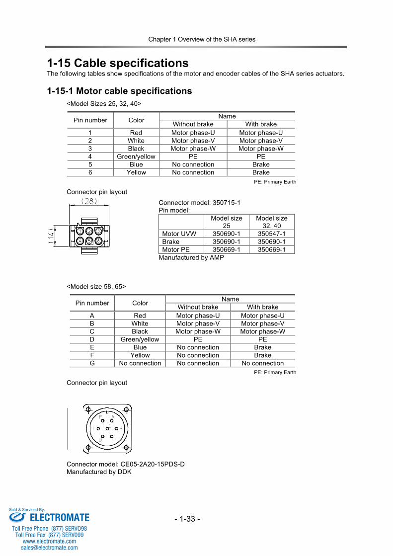
1-15 Cable specifications The following tables show specifications of the motor and encoder cables of the SHA series actuators.
1-15-1 Motor cable specifications
<Model Sizes 25, 32, 40>
Pin number Color Name Without brake With brake
1 Red Motor phase-U Motor phase-U 2 White Motor phase-V Motor phase-V 3 Black Motor phase-W Motor phase-W 4 Green/yellow PE PE 5 Blue No connection Brake 6 Yellow No connection Brake
Connector pin layout
<Model size 58, 65>
Pin number Color Name Without brake With brake
A Red Motor phase-U Motor phase-U B White Motor phase-V Motor phase-V C Black Motor phase-W Motor phase-W D Green/yellow PE PE E Blue No connection Brake F Yellow No connection Brake G No connection No connection No connection
Connector pin layout
Connector model: CE05-2A20-15PDS-D Manufactured by DDK
Connector model: 350715-1 Pin model: Model size
25 Model size
32, 40 Motor UVW 350690-1 350547-1 Brake 350690-1 350690-1 Motor PE 350669-1 350669-1
Manufactured by AMP
PE: Primary Earth
PE: Primary Earth
ELECTROMATEToll Free Phone (877) SERVO98
Toll Free Fax (877) SERV099www.electromate.com
Sold & Serviced By:
Chapter 1 Overview of the SHA series
- 1-34 -
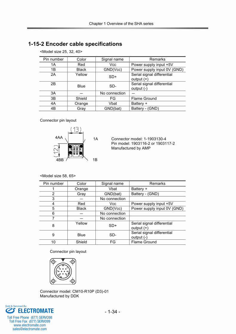
1-15-2 Encoder cable specifications
<Model size 25, 32, 40>
Pin number Color Signal name Remarks 1A Red Vcc Power supply input +5V 1B Black GND(Vcc) Power supply input 0V (GND) 2A Yellow SD+ Serial signal differential
output (+) 2B Blue SD- Serial signal differential
output (-) 3A ‐ No connection ‐ 3B Shield FG Flame Ground 4A Orange Vbat Battery + 4B Gray GND(bat) Battery - (GND)
Connector pin layout
<Model size 58, 65>
Pin number Color Signal name Remarks 1 Orange Vbat Battery + 2 Gray GND(bat) Battery - (GND) 3 ― No connection 4 Red Vcc Power supply input +5V 5 Black GND(Vcc) Power supply input 0V (GND) 6 ― No connection 7 ― No connection
8 Yellow SD+ Serial signal differential output (+)
9 Blue SD- Serial signal differential output (-)
10 Shield FG Flame Ground Connector pin layout
Connector model: CM10-R10P (D3)-01 Manufactured by DDK
Connector model: 1-1903130-4 Pin model: 1903116-2 or 1903117-2 Manufactured by AMP
1A
1B
4AA
4BB
ELECTROMATEToll Free Phone (877) SERVO98
Toll Free Fax (877) SERV099www.electromate.com
Sold & Serviced By:
Chapter 2 SHA series selection
2-1
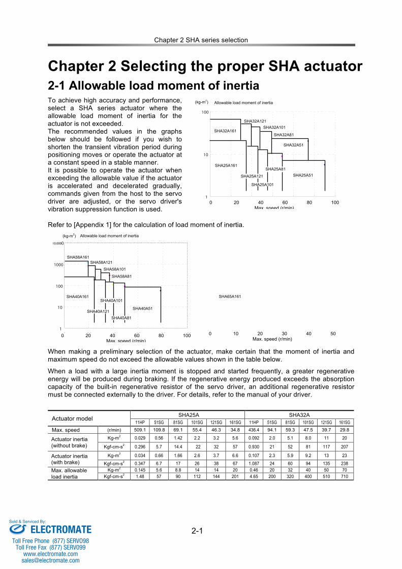
Chapter 2 Selecting the proper SHA actuator 2-1 Allowable load moment of inertia To achieve high accuracy and performance, select a SHA series actuator where the allowable load moment of inertia for the actuator is not exceeded. The recommended values in the graphs below should be followed if you wish to shorten the transient vibration period during positioning moves or operate the actuator at a constant speed in a stable manner. It is possible to operate the actuator when exceeding the allowable value if the actuator is accelerated and decelerated gradually, commands given from the host to the servo driver are adjusted, or the servo driver's vibration suppression function is used. Refer to [Appendix 1] for the calculation of load moment of inertia.
When making a preliminary selection of the actuator, make certain that the moment of inertia and maximum speed do not exceed the allowable values shown in the table below.
When a load with a large inertia moment is stopped and started frequently, a greater regenerative energy will be produced during braking. If the regenerative energy produced exceeds the absorption capacity of the built-in regenerative resistor of the servo driver, an additional regenerative resistor must be connected externally to the driver. For details, refer to the manual of your driver.
Actuator model SHA25A SHA32A 11HP 51SG 81SG 101SG 121SG 161SG 11HP 51SG 81SG 101SG 121SG 161SG
Max. speed (r/min) 509.1 109.8 69.1 55.4 46.3 34.8 436.4 94.1 59.3 47.5 39.7 29.8
Actuator inertia (without brake)
Kg-m2 0.029 0.56 1.42 2.2 3.2 5.6 0.092 2.0 5.1 8.0 11 20
Kgf-cm-s2 0.296 5.7 14.4 22 32 57 0.930 21 52 81 117 207
Actuator inertia (with brake)
Kg-m2 0.034 0.66 1.66 2.6 3.7 6.6 0.107 2.3 5.9 9.2 13 23
Kgf-cm-s2 0.347 6.7 17 26 38 67 1.087 24 60 94 135 238 Max. allowable load inertia
Kg-m2 0.145 5.6 8.8 14 14 20 0.46 20 32 40 50 70 Kgf-cm-s2 1.48 57 90 112 144 201 4.65 200 320 400 510 710
30 3
100r/min
1
10
100
0 20 40 60 80 100 120
SHA25A51
SHA32A51
SHA25A101
SHA32A101
SHA25A161
SHA32A161
Max. speed (r/min)
Allowable load moment of inertia
(kg-m2)
SHA25A121
SHA25A81
SHA32A81
SHA32A121
1
10
100
1000
10000
0 20 40 60 80 100
SHA40A51
SHA40A101 SHA40A161
SHA40A81 SHA40A121
SHA58A101
SHA58A161
SHA58A81
SHA58A121
0 20 40 60 80 100 Max. speed (r/min)
Allowable load moment of inertia (kg-m2)
SHA65A161 SHA65A161
10,000
0 20 40 60 80 100 Max. speed (r/min)
0 10 20 30 40 50 Max. speed (r/min)
ELECTROMATEToll Free Phone (877) SERVO98
Toll Free Fax (877) SERV099www.electromate.com
Sold & Serviced By:
Chapter 2 SHA series selection
2-2
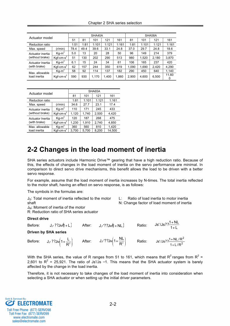
Actuator model SHA40A SHA58A
51 81 101 121 161 81 101 121 161 Reduction ratio 1:51 1:81 1:101 1:121 1:161 1:81 1:101 1:121 1:161 Max. speed (r/min) 78.4 49.4 39.6 33.1 24.8 37.0 29.7 24.8 18.6 Actuator inertia (without brake)
Kg-m2 5.0 13 20 28 50 96 149 214 379 Kgf-cm-s2 51 130 202 290 513 980 1,520 2,180 3,870
Actuator Inertia (with brake)
Kg-m2 6.1 15 24 34 61 106 165 237 420 Kgf-cm-s2 62 157 244 350 619 1,090 1,690 2,420 4,290
Max. allowable load inertia
Kg-m2 58 92 114 137 182 290 450 640 1,140
Kgf-cm-s2 590 930 1,170 1,400 1,860 2,900 4,600 6,500 11,600
Actuator model
SHA65A 81 101 121 161
Reduction ratio 1:81 1:101 1:121 1:161 Max. speed (r/min) 34.6 27.7 23.1 17.4 Actuator inertia (without brake)
Kg-m2 110 171 245 433 Kgf-cm-s2 1,120 1,740 2,500 4,420
Actuator Inertia (with brake)
Kg-m2 120 187 268 475 Kgf-cm-s2 1,230 1,910 2,740 4,850
Max. allowable load inertia
Kg-m2 360 560 810 1,420 Kgf-cm-s2 3,700 5,700 8,200 14,500
2-2 Changes in the load moment of inertia SHA series actuators include Harmonic Drive™ gearing that have a high reduction ratio. Because of this, the effects of changes in the load moment of inertia on the servo performance are minimal. In comparison to direct servo drive mechanisms, this benefit allows the load to be driven with a better servo response.
For example, assume that the load moment of inertia increases by N-times. The total inertia reflected to the motor shaft, having an effect on servo response, is as follows:
The symbols in the formulas are:
JS: Total moment of inertia reflected to the motor shaft JM: Moment of inertia of the motor R: Reduction ratio of SHA series actuator
L: Ratio of load inertia to motor inertia N: Change factor of load moment of inertia
Direct drive
Before: After: Ratio:
Driven by SHA series
Before: After: Ratio:
With the SHA series, the value of R ranges from 51 to 161, which means that R2 ranges from R2 = 2,601 to R2 = 25,921. The ratio of Js'/Js =1. This means that the SHA actuator system is barely affected by the change in the load inertia.
Therefore, it is not necessary to take changes of the load moment of inertia into consideration when selecting a SHA actuator or when setting up the initial driver parameters.
70r/min
50r/min
35r/min
Linear travel speed (mm/min)
Rotation speed (r/min)
L1
NL1/JsJs'
+
+??( )NL1J'J M +??,r( )L1JJ M +??,r
2
2
R/L1
R/NL1/JsJs'
+
+??
!!!
"
#
$$$
%
&+
2R
NL1J'J M??,r
!!!
"
#
$$$
%
&+
2R
L1JJ M??,r
ELECTROMATEToll Free Phone (877) SERVO98
Toll Free Fax (877) SERV099www.electromate.com
Sold & Serviced By:
Chapter 2 SHA series selection
2-3
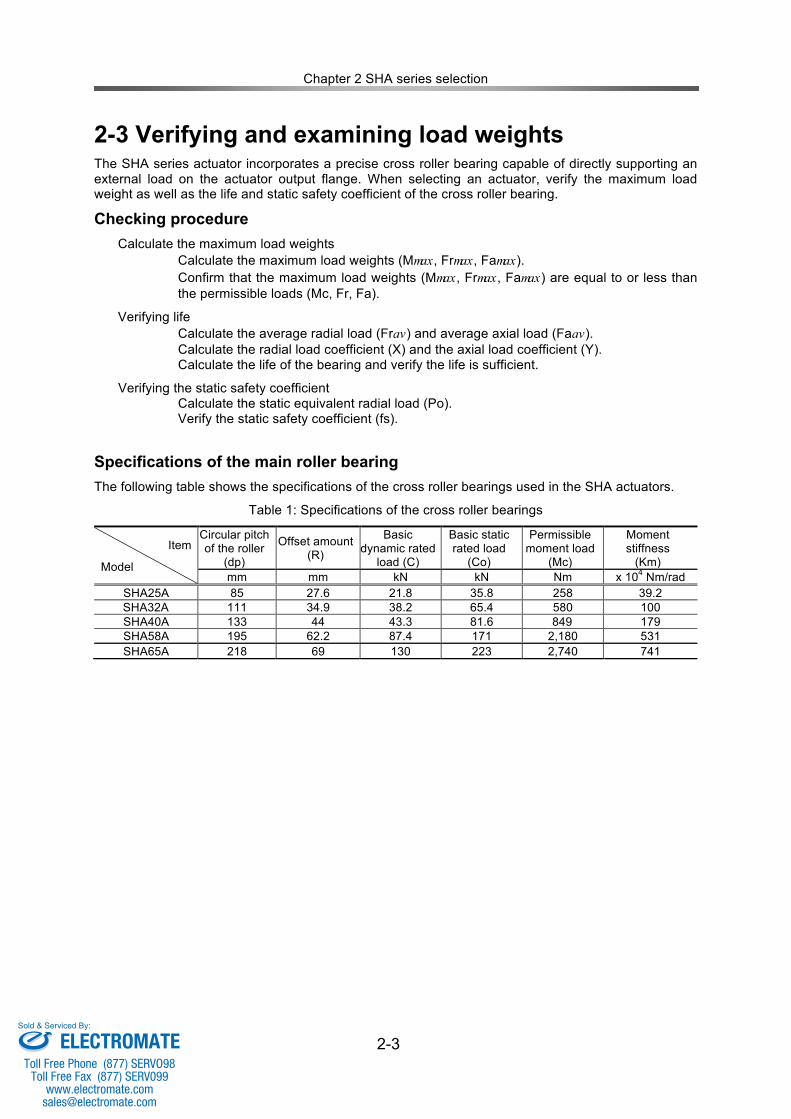
2-3 Verifying and examining load weights
The SHA series actuator incorporates a precise cross roller bearing capable of directly supporting an external load on the actuator output flange. When selecting an actuator, verify the maximum load weight as well as the life and static safety coefficient of the cross roller bearing.
Checking procedure Calculate the maximum load weights
Calculate the maximum load weights (Mmax, Frmax, Famax). Confirm that the maximum load weights (Mmax, Frmax, Famax) are equal to or less than the permissible loads (Mc, Fr, Fa).
Verifying life Calculate the average radial load (Frav) and average axial load (Faav). Calculate the radial load coefficient (X) and the axial load coefficient (Y). Calculate the life of the bearing and verify the life is sufficient.
Verifying the static safety coefficient Calculate the static equivalent radial load (Po). Verify the static safety coefficient (fs).
Specifications of the main roller bearing The following table shows the specifications of the cross roller bearings used in the SHA actuators.
Table 1: Specifications of the cross roller bearings
Item
Model
Circular pitch of the roller
(dp)
Offset amount (R)
Basic dynamic rated
load (C)
Basic static rated load
(Co)
Permissible moment load
(Mc)
Moment stiffness
(Km) mm mm kN kN Nm x 104 Nm/rad
SHA25A 85 27.6 21.8 35.8 258 39.2 SHA32A 111 34.9 38.2 65.4 580 100 SHA40A 133 44 43.3 81.6 849 179 SHA58A 195 62.2 87.4 171 2,180 531 SHA65A 218 69 130 223 2,740 741
ELECTROMATEToll Free Phone (877) SERVO98
Toll Free Fax (877) SERV099www.electromate.com
Sold & Serviced By:
Chapter 2 SHA series selection
2-4
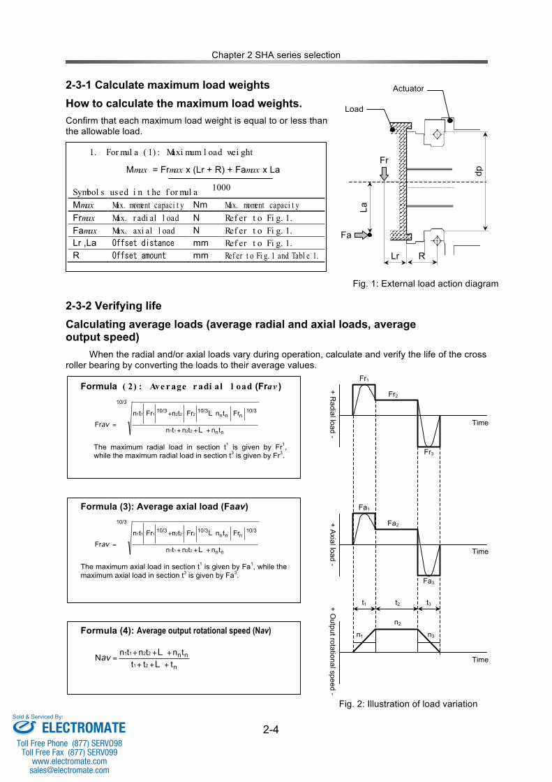
2-3-1 Calculate maximum load weights How to calculate the maximum load weights. Confirm that each maximum load weight is equal to or less than the allowable load.
2-3-2 Verifying life Calculating average loads (average radial and axial loads, average output speed)
When the radial and/or axial loads vary during operation, calculate and verify the life of the cross roller bearing by converting the loads to their average values.
1. For mul a ( 1) : Maxi mum l oad wei ght
Mmax = Frmax x (Lr + R) + Famax x La
Symbol s used i n t he f or mul a 1000 Mmax Max. moment capaci t y Nm Max. moment capaci t y Frmax Max. r adi al l oad N Ref er t o Fi g. 1. Famax Max. axi al l oad N Ref er t o Fi g. 1. Lr ,La Offset distance mm Ref er t o Fi g. 1. R Offset amount mm Ref er t o Fi g. 1 and Tabl e 1.
Fig. 1: External load action diagram
Time
+ Radial load -
Fr1
Fr2
Fr3
Time
+ Axial load -
Fa1
Fa2
Fa3
Time
+ Output rotational speed -
n1 n2
n3
t1 t2 t3
Formula ( 2) : Ave r age r adi al l oad (Frav )
nn
10/3 n nn
10/310/3
10/3
tntntn
Fr tnFr tnFr tn
Fr2211
2 22 1 11
+++
+
=L
L
av
The maximum radial load in section t1 is given by Fr1, while the maximum radial load in section t3 is given by Fr3.
Formula (3): Average axial load (Faav)
nn
10/3 n nn
10/310/3
10/3
tntntn
Fr tnFr tnFr tn
Fr2211
2 22 1 11
+++
+
=L
L
av
The maximum axial load in section t1 is given by Fa1, while the maximum axial load in section t3 is given by Fa3.
Formula (4): Average output rotational speed (Nav)
n
nn
ttt
tntntnN
21
2211
+++
+++=
L
Lav
Fig. 2: Illustration of load variation
dp Fr
R Lr
Actuator
La
Fa
Load
ELECTROMATEToll Free Phone (877) SERVO98
Toll Free Fax (877) SERV099www.electromate.com
Sold & Serviced By:
Chapter 2 SHA series selection
2-5
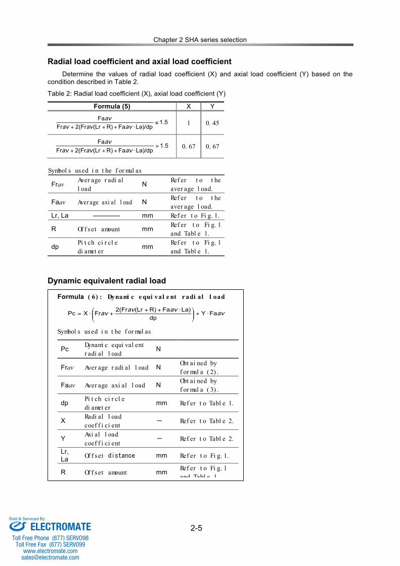
Radial load coefficient and axial load coefficient Determine the values of radial load coefficient (X) and axial load coefficient (Y) based on the condition described in Table 2.
Table 2: Radial load coefficient (X), axial load coefficient (Y)
Formula (5) X Y
5.1La)/dpFaR)(Lr2(FrFr
Fa!
"+++ avavav
av 1 0. 45
1.5La)/dpFaR)(Lr2(FrFr
Fa>
!+++ avavav
av 0. 67 0. 67
Dynamic equivalent radial load
Symbol s used i n t he f or mul as
Frav Aver age r adi al l oad
N Ref er t o t he aver age l oad.
Faav Aver age axi al l oad N Ref er t o t he aver age l oad.
Lr, La ―――― mm Ref er t o Fi g. 1.
R Of f set amount mm Ref er t o Fi g. 1 and Tabl e 1.
dp Pi t ch ci r cl e di amet er
mm Ref er t o Fi g. 1 and Tabl e 1.
Formula ( 6) : Dynami c e qui val e nt r adi al l oad
avavav
av FaYdp
La)FaR)(Lr2(FrFrXPc !+""
#
$%%&
' !+++!=
Symbol s used i n t he f or mul as
Pc Dynami c equi val ent r adi al l oad
N
Frav Aver age r adi al l oad N Obt ai ned by f or mul a ( 2) .
Faav Aver age axi al l oad N Obt ai ned by f or mul a ( 3) .
dp Pi t ch ci r cl e di amet er
mm Ref er t o Tabl e 1.
X Radi al l oad coef f i ci ent
‐ Ref er t o Tabl e 2.
Y Axi al l oad coef f i ci ent
‐ Ref er t o Tabl e 2.
Lr, La Of f set distance mm Ref er t o Fi g. 1.
R Of f set amount mm Ref er t o Fi g. 1 and Tabl e 1.
ELECTROMATEToll Free Phone (877) SERVO98
Toll Free Fax (877) SERV099www.electromate.com
Sold & Serviced By:
Chapter 2 SHA series selection
2-6
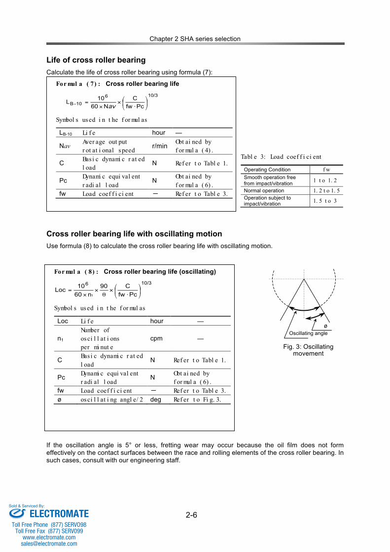
Life of cross roller bearing Calculate the life of cross roller bearing using formula (7):
Cross roller bearing life with oscillating motion Use formula (8) to calculate the cross roller bearing life with oscillating motion.
If the oscillation angle is 5° or less, fretting wear may occur because the oil film does not form effectively on the contact surfaces between the race and rolling elements of the cross roller bearing. In such cases, consult with our engineering staff.
For mul a ( 7) : Cross roller bearing life 10/36
10BPcfw
C
N60
10L !
"
#$%
&
'(
(=)
av
Symbol s used i n t he f or mul as
LB-10 Li f e hour ―
Nav Aver age out put r ot at i onal speed r/min Obt ai ned by
f or mul a ( 4) .
C Bas i c dynami c r at ed l oad
N Ref er t o Tabl e 1.
Pc Dynami c equi val ent r adi al l oad
N Obt ai ned by f or mul a ( 6) .
fw Load coef f i ci ent ‐ Ref er t o Tabl e 3.
Tabl e 3: Load coef f i ci ent
Operating Condition f w Smooth operation free from impact/vibration 1 t o 1. 2
Normal operation 1. 2 t o 1. 5 Operation subject to impact/vibration 1. 5 t o 3
For mul a ( 8) : Cross roller bearing life (oscillating) 10/36
Pcfw
C90
n60
10Loc
1
!"
#$%
&
'(
)(
(=
Symbol s used i n t he f or mul as
Loc Li f e hour ―
n1 Number of osci l l at i ons per mi nut e
cpm ―
C Bas i c dynami c r at ed l oad
N Ref er t o Tabl e 1.
Pc Dynami c equi val ent r adi al l oad
N Obt ai ned by f or mul a ( 6) .
fw Load coef f i ci ent ‐ Ref er t o Tabl e 3. ø osci l l at i ng angl e/ 2 deg Ref er t o Fi g. 3.
Oscillating angle ø
Fig. 3: Oscillating movement
ELECTROMATEToll Free Phone (877) SERVO98
Toll Free Fax (877) SERV099www.electromate.com
Sold & Serviced By:
Chapter 2 SHA series selection
2-7
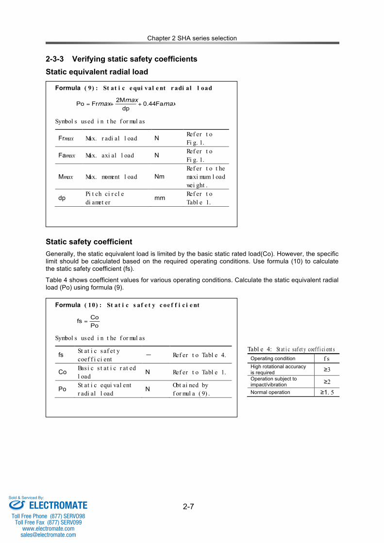
2-3-3 Verifying static safety coefficients Static equivalent radial load
Static safety coefficient Generally, the static equivalent load is limited by the basic static rated load(Co). However, the specific limit should be calculated based on the required operating conditions. Use formula (10) to calculate the static safety coefficient (fs).
Table 4 shows coefficient values for various operating conditions. Calculate the static equivalent radial load (Po) using formula (9).
Formula ( 9) : St at i c e qui val e nt r adi al l oad
maxmax
max Fa44.0dp
2MFrPo ++=
Symbol s used i n t he f or mul as
Frmax Max. r adi al l oad N Ref er t o Fi g. 1.
Famax Max. axi al l oad N Ref er t o Fi g. 1.
Mmax Max. moment l oad Nm Ref er t o t he maxi mum l oad wei ght .
dp Pi t ch ci r cl e di amet er
mm Ref er t o Tabl e 1.
Formula ( 10) : St at i c s af e t y c oe f f i c i e nt
Po
Cofs =
Symbol s used i n t he f or mul as
fs St at i c saf et y coef f i ci ent
‐ Ref er t o Tabl e 4.
Co Bas i c s t at i c r at ed l oad
N Ref er t o Tabl e 1.
Po St at i c equi val ent r adi al l oad
N Obt ai ned by f or mul a ( 9) .
Tabl e 4: St at i c saf et y coef f i ci ent s Operating condition f s High rotational accuracy is required ≥3 Operation subject to impact/vibration ≥2 Normal operation ≥1. 5
ELECTROMATEToll Free Phone (877) SERVO98
Toll Free Fax (877) SERV099www.electromate.com
Sold & Serviced By:
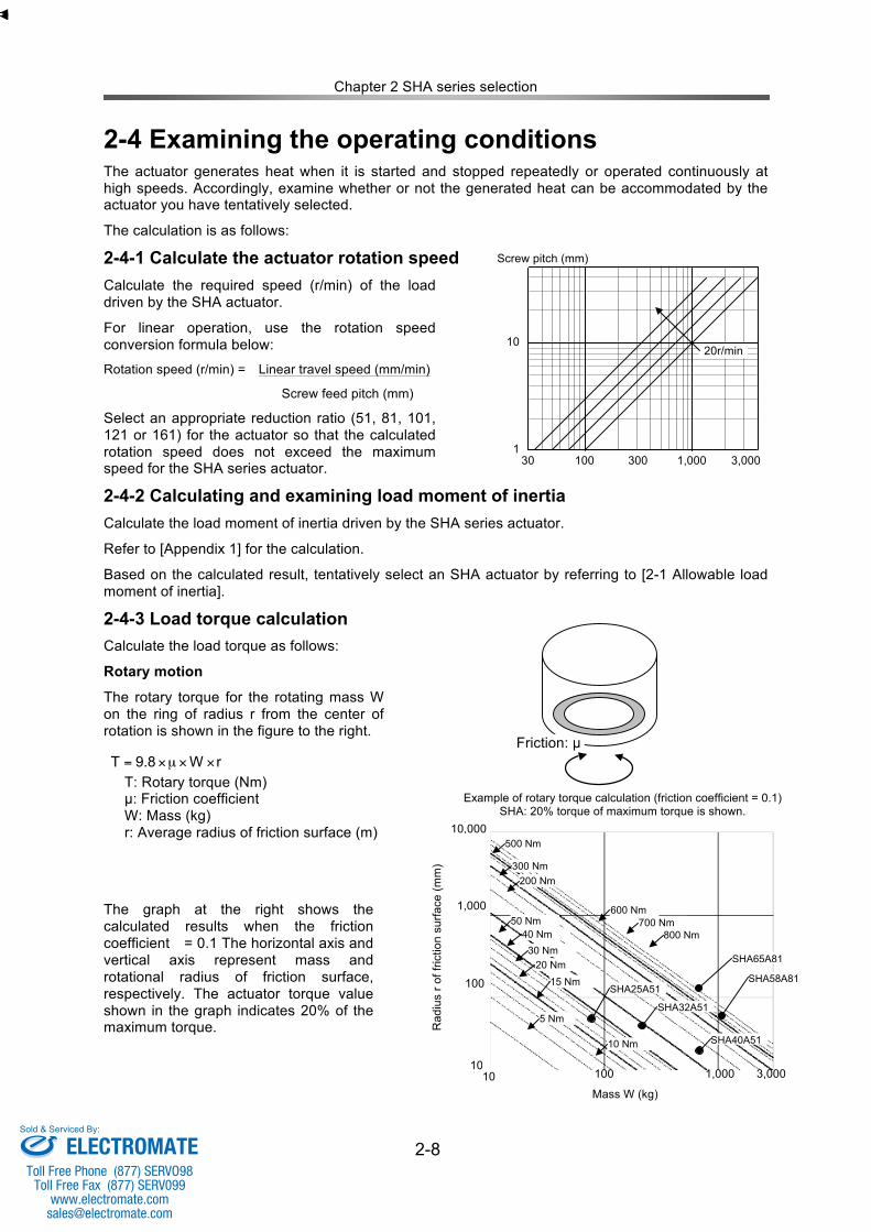
Chapter 2 SHA series selection
2-8
2-4 Examining the operating conditions The actuator generates heat when it is started and stopped repeatedly or operated continuously at high speeds. Accordingly, examine whether or not the generated heat can be accommodated by the actuator you have tentatively selected.
The calculation is as follows:
2-4-1 Calculate the actuator rotation speed Calculate the required speed (r/min) of the load driven by the SHA actuator.
For linear operation, use the rotation speed conversion formula below:
Rotation speed (r/min) = Linear travel speed (mm/min)
Screw feed pitch (mm)
Select an appropriate reduction ratio (51, 81, 101, 121 or 161) for the actuator so that the calculated rotation speed does not exceed the maximum speed for the SHA series actuator.
2-4-2 Calculating and examining load moment of inertia Calculate the load moment of inertia driven by the SHA series actuator.
Refer to [Appendix 1] for the calculation.
Based on the calculated result, tentatively select an SHA actuator by referring to [2-1 Allowable load moment of inertia].
2-4-3 Load torque calculation Calculate the load torque as follows:
Rotary motion
The rotary torque for the rotating mass W on the ring of radius r from the center of rotation is shown in the figure to the right.
T: Rotary torque (Nm) µ: Friction coefficient W: Mass (kg) r: Average radius of friction surface (m)
The graph at the right shows the calculated results when the friction coefficient = 0.1 The horizontal axis and vertical axis represent mass and rotational radius of friction surface, respectively. The actuator torque value shown in the graph indicates 20% of the maximum torque.
100 1,000 3,000 30 300 1
10
30 3
100r/min
70r/min
50r/min
35r/min
Linear travel speed (mm/min)
Screw pitch (mm)
Rotation speed (r/min)
20r/min
Mass: W
Friction: µ rW8.9T !!µ!=
Example of rotary torque calculation (friction coefficient = 0.1) SHA: 20% torque of maximum torque is shown.
500 Nm 10,000
300 Nm
Rad
ius
r of f
rictio
n su
rface
(mm
)
200 Nm
600 Nm 700 Nm
1,000
SHA65A81
SHA25A51
5 Nm
15 Nm 20 Nm
30 Nm 40 Nm
50 Nm 800 Nm
SHA32A51
SHA58A81 100
10 Nm SHA40A51
10 10
3,000 1,000 100
Mass W (kg)
500 Nm
ELECTROMATEToll Free Phone (877) SERVO98
Toll Free Fax (877) SERV099www.electromate.com
Sold & Serviced By:
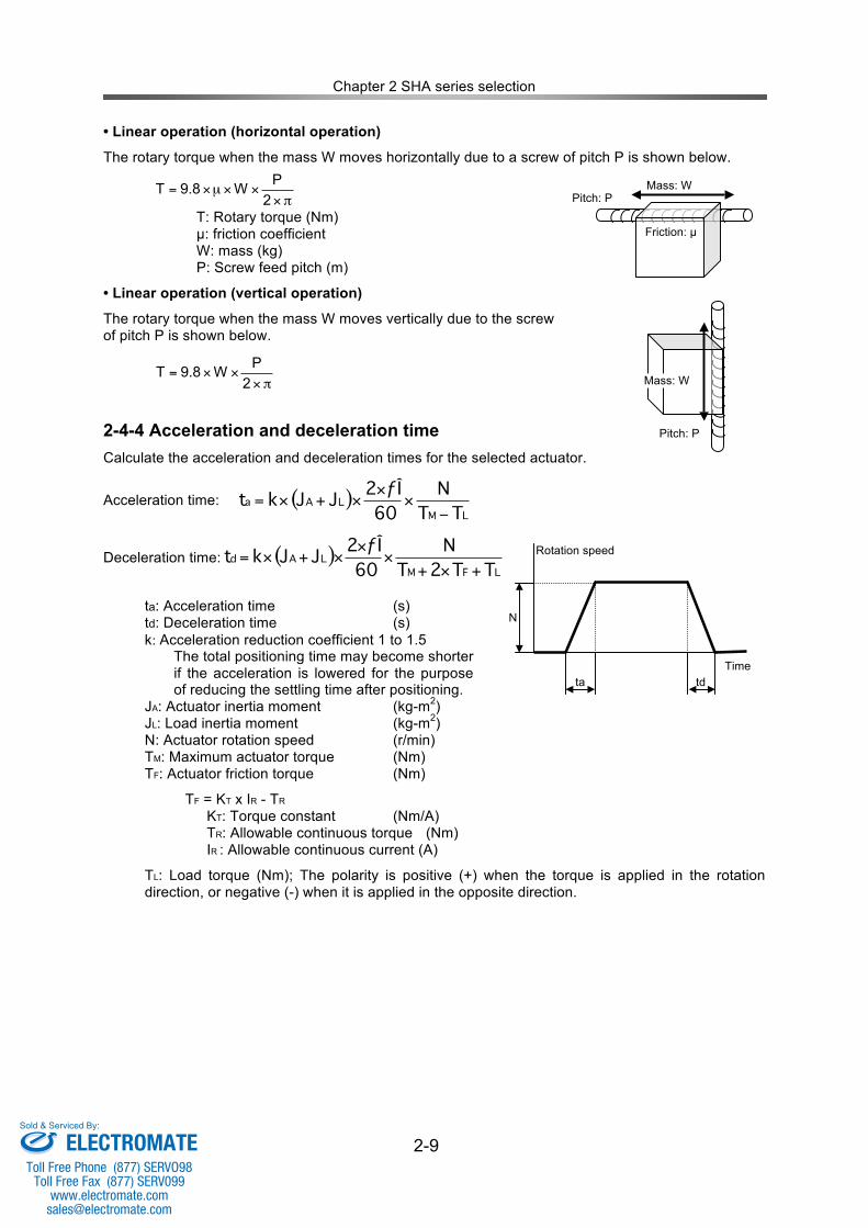
Chapter 2 SHA series selection
2-9
• Linear operation (horizontal operation)
The rotary torque when the mass W moves horizontally due to a screw of pitch P is shown below.
T: Rotary torque (Nm) µ: friction coefficient W: mass (kg) P: Screw feed pitch (m)
• Linear operation (vertical operation)
The rotary torque when the mass W moves vertically due to the screw of pitch P is shown below.
2-4-4 Acceleration and deceleration time Calculate the acceleration and deceleration times for the selected actuator.
Acceleration time:
Deceleration time: ( )LFM
LAdTT2T
N
60
ƒÎ2JJkt
+!+!
!!+!=
ta: Acceleration time (s) td: Deceleration time (s) k: Acceleration reduction coefficient 1 to 1.5 The total positioning time may become shorter
if the acceleration is lowered for the purpose of reducing the settling time after positioning.
JA: Actuator inertia moment (kg-m2) JL: Load inertia moment (kg-m2) N: Actuator rotation speed (r/min) TM: Maximum actuator torque (Nm) TF: Actuator friction torque (Nm)
TF = KT x IR - TR KT: Torque constant (Nm/A) TR: Allowable continuous torque (Nm) IR : Allowable continuous current (A)
TL: Load torque (Nm); The polarity is positive (+) when the torque is applied in the rotation direction, or negative (-) when it is applied in the opposite direction.
!"""µ"=2
PW8.9T Mass: W
Pitch: P
Friction: µ
Pitch: P
Mass: W !"""=2
PW8.9T
( )LM
LAaTT
N
60
ƒÎ2JJkt
!"
""+"=
ta td
N
Time
Rotation speed
ELECTROMATEToll Free Phone (877) SERVO98
Toll Free Fax (877) SERV099www.electromate.com
Sold & Serviced By:
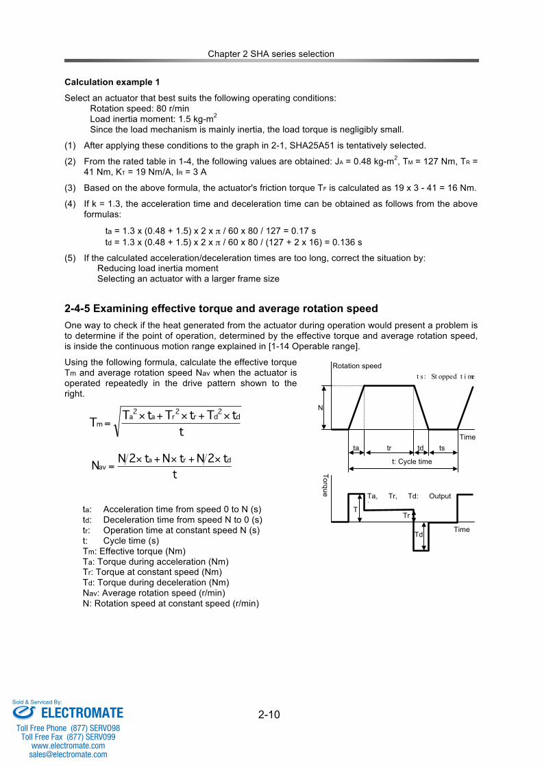
Chapter 2 SHA series selection
2-10
Calculation example 1
Select an actuator that best suits the following operating conditions: Rotation speed: 80 r/min Load inertia moment: 1.5 kg-m2 Since the load mechanism is mainly inertia, the load torque is negligibly small.
(1) After applying these conditions to the graph in 2-1, SHA25A51 is tentatively selected.
(2) From the rated table in 1-4, the following values are obtained: JA = 0.48 kg-m2, TM = 127 Nm, TR = 41 Nm, KT = 19 Nm/A, IR = 3 A
(3) Based on the above formula, the actuator's friction torque TF is calculated as 19 x 3 - 41 = 16 Nm.
(4) If k = 1.3, the acceleration time and deceleration time can be obtained as follows from the above formulas:
ta = 1.3 x (0.48 + 1.5) x 2 x π / 60 x 80 / 127 = 0.17 s td = 1.3 x (0.48 + 1.5) x 2 x π / 60 x 80 / (127 + 2 x 16) = 0.136 s
(5) If the calculated acceleration/deceleration times are too long, correct the situation by: Reducing load inertia moment Selecting an actuator with a larger frame size
2-4-5 Examining effective torque and average rotation speed One way to check if the heat generated from the actuator during operation would present a problem is to determine if the point of operation, determined by the effective torque and average rotation speed, is inside the continuous motion range explained in [1-14 Operable range].
Using the following formula, calculate the effective torque Tm and average rotation speed Nav when the actuator is operated repeatedly in the drive pattern shown to the right.
ta: Acceleration time from speed 0 to N (s) td: Deceleration time from speed N to 0 (s) tr: Operation time at constant speed N (s) t: Cycle time (s) Tm: Effective torque (Nm) Ta: Torque during acceleration (Nm) Tr: Torque at constant speed (Nm) Td: Torque during deceleration (Nm) Nav: Average rotation speed (r/min) N: Rotation speed at constant speed (r/min)
Time
ta td
N
tr Time
Rotation speed
t: Cycle time
ts
Ta
Torque
Td
Tr
t s : St opped t i me
Ta, Tr, Td: Output torques
t
tTtTtTT
d2
dr2ra
2a
m
!+!+!=
t
t2NtNt2NN
dra
av
!+!+!=
ELECTROMATEToll Free Phone (877) SERVO98
Toll Free Fax (877) SERV099www.electromate.com
Sold & Serviced By:
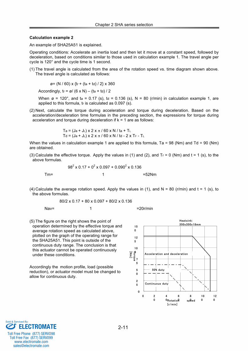
Chapter 2 SHA series selection
2-11
Calculation example 2
An example of SHA25A51 is explained.
Operating conditions: Accelerate an inertia load and then let it move at a constant speed, followed by deceleration, based on conditions similar to those used in calculation example 1. The travel angle per cycle is 120° and the cycle time is 1 second.
(1) The travel angle is calculated from the area of the rotation speed vs. time diagram shown above. The travel angle is calculated as follows:
ø= (N / 60) x {tr + (ta + td) / 2} x 360
Accordingly, tr = ø/ (6 x N) – (ta + td) / 2
When ø = 120°, and ta = 0.17 (s), td = 0.136 (s), N = 80 (r/min) in calculation example 1, are applied to this formula, tr is calculated as 0.097 (s).
(2) Next, calculate the torque during acceleration and torque during deceleration. Based on the acceleration/deceleration time formulas in the preceding section, the expressions for torque during acceleration and torque during deceleration if k = 1 are as follows:
Ta = (Ja + JL) x 2 x π / 60 x N / ta + TL Td = (Ja + JL) x 2 x π / 60 x N / td - 2 x TF - TL
When the values in calculation example 1 are applied to this formula, Ta = 98 (Nm) and Td = 90 (Nm) are obtained.
(3) Calculate the effective torque. Apply the values in (1) and (2), and Tr = 0 (Nm) and t = 1 (s), to the above formulas.
982 x 0.17 + 02 x 0.097 + 0.0902 x 0.136
Tm= 1 =52Nm
(4) Calculate the average rotation speed. Apply the values in (1), and N = 80 (r/min) and t = 1 (s), to the above formulas.
80/2 x 0.17 + 80 x 0.097 + 80/2 x 0.136
Nav= 1 =20r/min
(5) The figure on the right shows the point of
operation determined by the effective torque and average rotation speed as calculated above, plotted on the graph of the operating range for the SHA25A51. This point is outside of the continuous duty range. The conclusion is that this actuator cannot be operated continuously under these conditions.
Accordingly the motion profile, load (possible reduction), or actuator model must be changed to allow for continuous duty.
Mass: W
Operating range of SHA25A51
★
Heatsink:
350x350x18mm
0
2
5
5
0
7
5
10
0
12
5
15
0
0 2
0 4
0 6
0 8
0 10
0 12
0 Rotation speed
[r/min]
Acceleration and deceleration
Continuous duty
50% duty
Torque
[Nm]
ELECTROMATEToll Free Phone (877) SERVO98
Toll Free Fax (877) SERV099www.electromate.com
Sold & Serviced By:
Chapter 2 SHA series selection
2-12
The following formula is a modified version of the formula for calculating effective torque. By applying the value of allowable continuous torque to Tm in this formula, the allowable cycle time can be calculated.
2
222
m
ddrraa
T
tTtTtTt
!+!+!=
Apply the following: Ta = 98 Nm, Tr = 0 Nm, Td = 90 Nm, Tm = 41 Nm, ta = 0.17 s, tr = 0.097 s, td = 0.136 s Then, the following equation is obtained:
t = (982 x 0.17 + 902 x 0.136) / 412 = 1.64 s
Based on the result, setting the cycle time to 1.7 seconds or more to provide a longer stopped time gives Tm = 41 Nm or less, thereby permitting continuous operation within the allowable continuous torque.
Notice
The aforementioned continuous duty range represents an allowable range when the actuator is installed on the specified aluminum heatsink and operated under natural air cooling. If the radiation area of the mounting member is smaller or the heat conduction of the material is poor, adjust the operating conditions to limit the temperature rise of the actuator to 40º C or less.
ELECTROMATEToll Free Phone (877) SERVO98
Toll Free Fax (877) SERV099www.electromate.com
Sold & Serviced By:
Chapter 3 Installing the SHA actuator
- 3-1 -
Chapter 3 Installing the SHA actuator 3-1 Receiving Inspection Check the following items after unpacking the actuator.
Inspection procedure (1) Check the items thoroughly for any damage sustained during transportation. If any item is
damaged, immediately contact the seller.
(2) The nameplate is found on the rear face of the SHA series actuator. Check the TYPE field on the nameplate to confirm that it is indeed the model you have ordered. If any item is wrong, immediately contact the seller.
Refer to the section 1-2 in this manual for the details of the model codes.
(3) The applicable SHA series actuator models are shown in the ADJUSTED FOR USE WITH field of the nameplate on the HA-800 driver. Make sure your actuator is combined with the correct driver.
(4) The driver's model code is shown in the TYPE field of the driver's nameplate. The last three digits of this model code indicate the input voltage to be input.
200: 3-phase/single-phase 200V power supply
If the voltage to be supplied is different from the label voltage, immediately contact the seller it was purchased from.
Only connect the actuator specified on the driver label. The characteristics of this driver have been adjusted according to the actuator. Wrong combinations of drivers and actuators may cause low torque problems or over-current that may cause thermal damage to the actuator, injury or fire. WARNING
Do not connect a supply voltage other than the voltage specified on the driver label. The wrong power supply voltage may damage the driver resulting in physical injury and fire. WARNING
ELECTROMATEToll Free Phone (877) SERVO98
Toll Free Fax (877) SERV099www.electromate.com
Sold & Serviced By:
Chapter 3 Installing the SHA actuator
- 3-2 -
3-2 Notices on handling Handle the SHA series actuator carefully by observing the notices specified below.
(1) Do not apply any excessive force or impact, especially to the actuator's output shaft.
(2) Do not put the SHA series actuator on a table, shelf, etc., where the actuator could easily fall.
(3) Do not connect the actuator terminals directly to a power supply (line voltage). The actuator may burn and cause a fire or electric shock.
(4) The allowable storage temperature is -20 to +60°C. Do not expose the actuator to direct sunlight for long periods of time or store it in areas in low or high temperature.
(5) The allowable relative storage humidity is 80% or less. Do not store the actuator in a very humid place or in areas where temperatures are likely to fluctuate greatly during day and night.
(6) Do not use or store the actuator in locations subject to flammable or corrosive gases or dust particles.
(7) The large models (SHA58A, SHA65A) are heavy. Handling these models may cause lower back pain or injury. Injury may occur if the actuator falls and you are pinned underneath. Handle your actuators with due care and wear safety shoes or take other proper precaution. Use supporting fixtures and lifting equipment as necessary for safe handling.
CAUTION
ELECTROMATEToll Free Phone (877) SERVO98
Toll Free Fax (877) SERV099www.electromate.com
Sold & Serviced By:
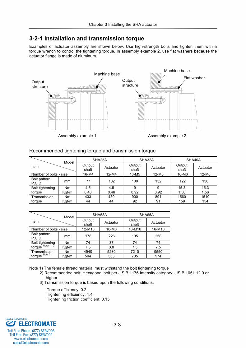
Chapter 3 Installing the SHA actuator
- 3-3 -
3-2-1 Installation and transmission torque Examples of actuator assembly are shown below. Use high-strength bolts and tighten them with a torque wrench to control the tightening torque. In assembly example 2, use flat washers because the actuator flange is made of aluminum.
Assembly example 1 Assembly example 2
Recommended tightening torque and transmission torque
Model Item
SHA25A SHA32A SHA40A Output shaft Actuator Output
shaft Actuator Output shaft Actuator
Number of bolts - size 16-M4 12-M4 16-M5 12-M5 16-M6 12-M6 Bolt pattern P.C.D. mm 77 102 100 132 122 158
Bolt tightening torque
Nm 4.5 4.5 9 9 15.3 15.3 Kgf-m 0.46 0.46 0.92 0.92 1.56 1.56
Transmission torque
Nm 433 430 900 891 1560 1510 Kgf-m 44 44 92 91 159 154
Model Item
SHA58A SHA65A Output shaft Actuator Output
shaft Actuator
Number of bolts - size 12-M10 16-M8 16-M10 16-M10 Bolt pattern P.C.D. mm 178 226 195 258
Bolt tightening torque Notes 1, 2
Nm 74 37 74 74 Kgf-m 7.5 3.8 7.5 7.5
Transmission torque Note 3
Nm 4940 5230 7210 9550 Kgf-m 504 533 735 974
Note 1) The female thread material must withstand the bolt tightening torque 2) Recommended bolt: Hexagonal bolt per JIS B 1176 Intensity category: JIS B 1051 12.9 or higher 3) Transmission torque is based upon the following conditions:
Torque efficiency: 0.2 Tightening efficiency: 1.4 Tightening friction coefficient: 0.15
Machine base
Output structure
Output structure
Machine base
Flat washer
ELECTROMATEToll Free Phone (877) SERVO98
Toll Free Fax (877) SERV099www.electromate.com
Sold & Serviced By:
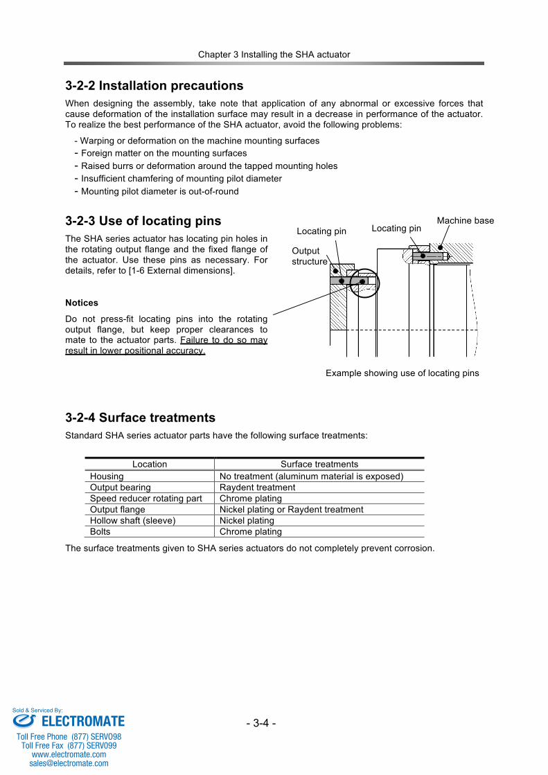
Chapter 3 Installing the SHA actuator
- 3-4 -
3-2-2 Installation precautions When designing the assembly, take note that application of any abnormal or excessive forces that cause deformation of the installation surface may result in a decrease in performance of the actuator. To realize the best performance of the SHA actuator, avoid the following problems:
- Warping or deformation on the machine mounting surfaces - Foreign matter on the mounting surfaces - Raised burrs or deformation around the tapped mounting holes - Insufficient chamfering of mounting pilot diameter - Mounting pilot diameter is out-of-round
3-2-3 Use of locating pins The SHA series actuator has locating pin holes in the rotating output flange and the fixed flange of the actuator. Use these pins as necessary. For details, refer to [1-6 External dimensions].
Notices
Do not press-fit locating pins into the rotating output flange, but keep proper clearances to mate to the actuator parts. Failure to do so may result in lower positional accuracy.
3-2-4 Surface treatments Standard SHA series actuator parts have the following surface treatments:
Location Surface treatments Housing No treatment (aluminum material is exposed) Output bearing Raydent treatment Speed reducer rotating part Chrome plating Output flange Nickel plating or Raydent treatment Hollow shaft (sleeve) Nickel plating Bolts Chrome plating
The surface treatments given to SHA series actuators do not completely prevent corrosion.
Output structure
Machine base Locating pin Locating pin
Example showing use of locating pins
ELECTROMATEToll Free Phone (877) SERVO98
Toll Free Fax (877) SERV099www.electromate.com
Sold & Serviced By:
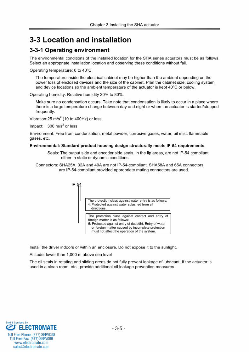
Chapter 3 Installing the SHA actuator
- 3-5 -
3-3 Location and installation 3-3-1 Operating environment The environmental conditions of the installed location for the SHA series actuators must be as follows. Select an appropriate installation location and observing these conditions without fail.
Operating temperature: 0 to 40ºC
The temperature inside the electrical cabinet may be higher than the ambient depending on the power loss of enclosed devices and the size of the cabinet. Plan the cabinet size, cooling system, and device locations so the ambient temperature of the actuator is kept 40ºC or below.
Operating humidity: Relative humidity 20% to 80%.
Make sure no condensation occurs. Take note that condensation is likely to occur in a place where there is a large temperature change between day and night or when the actuator is started/stopped frequently.
Vibration: 25 m/s2 (10 to 400Hz) or less
Impact: 300 m/s2 or less
Environment: Free from condensation, metal powder, corrosive gases, water, oil mist, flammable gases, etc.
Environmental: Standard product housing design structurally meets IP-54 requirements.
Seals: The output side and encoder side seals, in the lip areas, are not IP-54 compliant either in static or dynamic conditions.
Connectors: SHA25A, 32A and 40A are not IP-54-compliant. SHA58A and 65A connectors are IP-54-compliant provided appropriate mating connectors are used.
IP-54
Install the driver indoors or within an enclosure. Do not expose it to the sunlight.
Altitude: lower than 1,000 m above sea level
The oil seals in rotating and sliding areas do not fully prevent leakage of lubricant. If the actuator is used in a clean room, etc., provide additional oil leakage prevention measures.
The protection class against contact and entry of foreign matter is as follows: 5: Protected against entry of dust/dirt. Entry of water or foreign matter caused by incomplete protection must not affect the operation of the system.
The protection class against water entry is as follows: 4: Protected against water splashed from all directions.
ELECTROMATEToll Free Phone (877) SERVO98
Toll Free Fax (877) SERV099www.electromate.com
Sold & Serviced By:
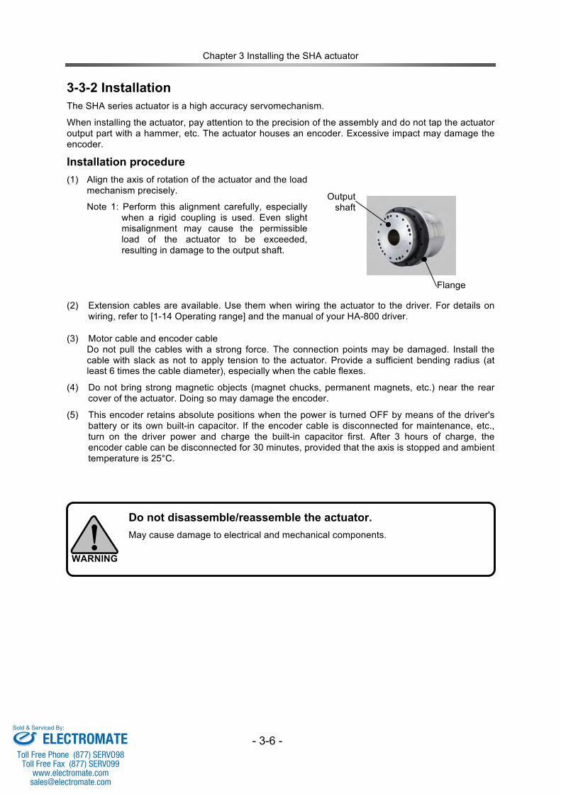
Chapter 3 Installing the SHA actuator
- 3-6 -
3-3-2 Installation
The SHA series actuator is a high accuracy servomechanism.
When installing the actuator, pay attention to the precision of the assembly and do not tap the actuator output part with a hammer, etc. The actuator houses an encoder. Excessive impact may damage the encoder.
Installation procedure (1) Align the axis of rotation of the actuator and the load
mechanism precisely.
Note 1: Perform this alignment carefully, especially when a rigid coupling is used. Even slight misalignment may cause the permissible load of the actuator to be exceeded, resulting in damage to the output shaft.
(2) Extension cables are available. Use them when wiring the actuator to the driver. For details on wiring, refer to [1-14 Operating range] and the manual of your HA-800 driver.
(3) Motor cable and encoder cable Do not pull the cables with a strong force. The connection points may be damaged. Install the cable with slack as not to apply tension to the actuator. Provide a sufficient bending radius (at least 6 times the cable diameter), especially when the cable flexes.
(4) Do not bring strong magnetic objects (magnet chucks, permanent magnets, etc.) near the rear cover of the actuator. Doing so may damage the encoder.
(5) This encoder retains absolute positions when the power is turned OFF by means of the driver's battery or its own built-in capacitor. If the encoder cable is disconnected for maintenance, etc., turn on the driver power and charge the built-in capacitor first. After 3 hours of charge, the encoder cable can be disconnected for 30 minutes, provided that the axis is stopped and ambient temperature is 25°C.
Output shaft
Flange
Do not disassemble/reassemble the actuator. May cause damage to electrical and mechanical components.
WARNING
ELECTROMATEToll Free Phone (877) SERVO98
Toll Free Fax (877) SERV099www.electromate.com
Sold & Serviced By:
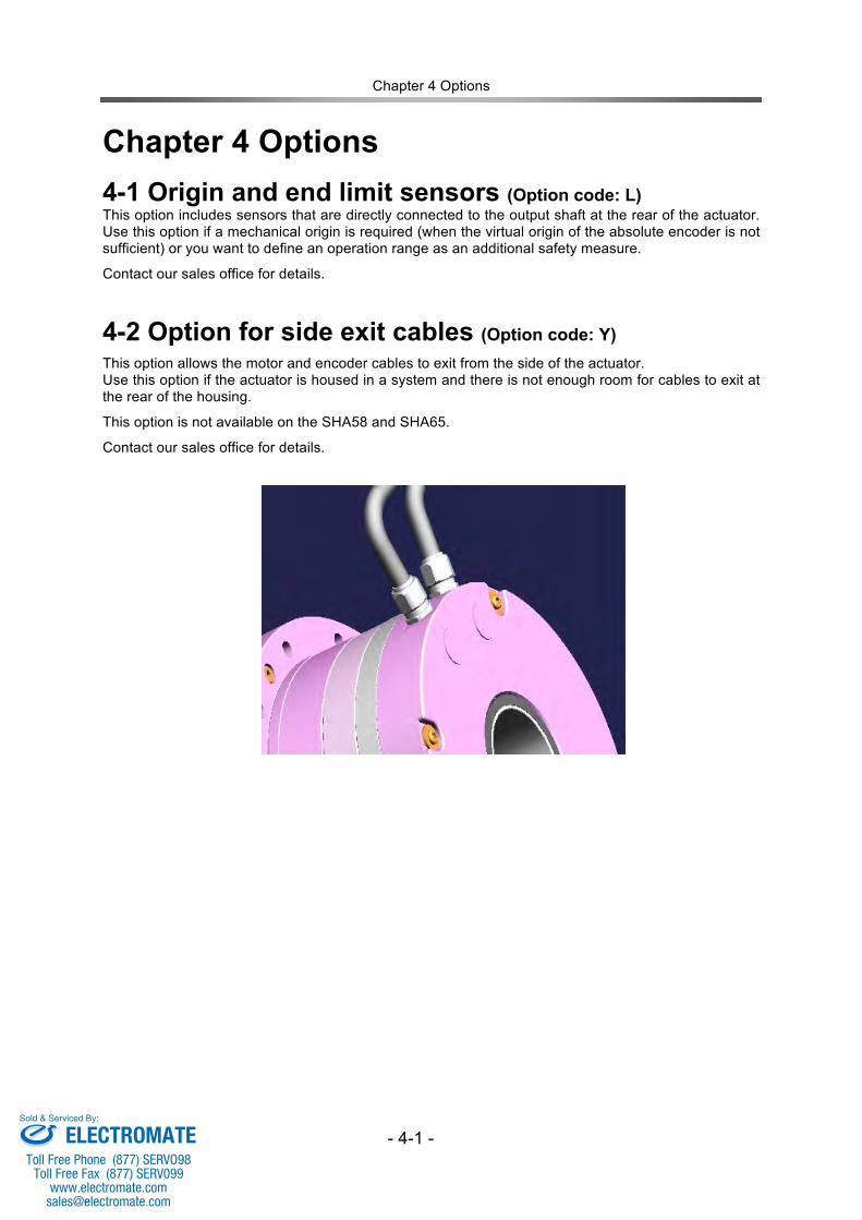
Chapter 4 Options
- 4-1 -
Chapter 4 Options 4-1 Origin and end limit sensors (Option code: L) This option includes sensors that are directly connected to the output shaft at the rear of the actuator. Use this option if a mechanical origin is required (when the virtual origin of the absolute encoder is not sufficient) or you want to define an operation range as an additional safety measure.
Contact our sales office for details.
4-2 Option for side exit cables (Option code: Y) This option allows the motor and encoder cables to exit from the side of the actuator. Use this option if the actuator is housed in a system and there is not enough room for cables to exit at the rear of the housing.
This option is not available on the SHA58 and SHA65.
Contact our sales office for details.
ELECTROMATEToll Free Phone (877) SERVO98
Toll Free Fax (877) SERV099www.electromate.com
Sold & Serviced By:
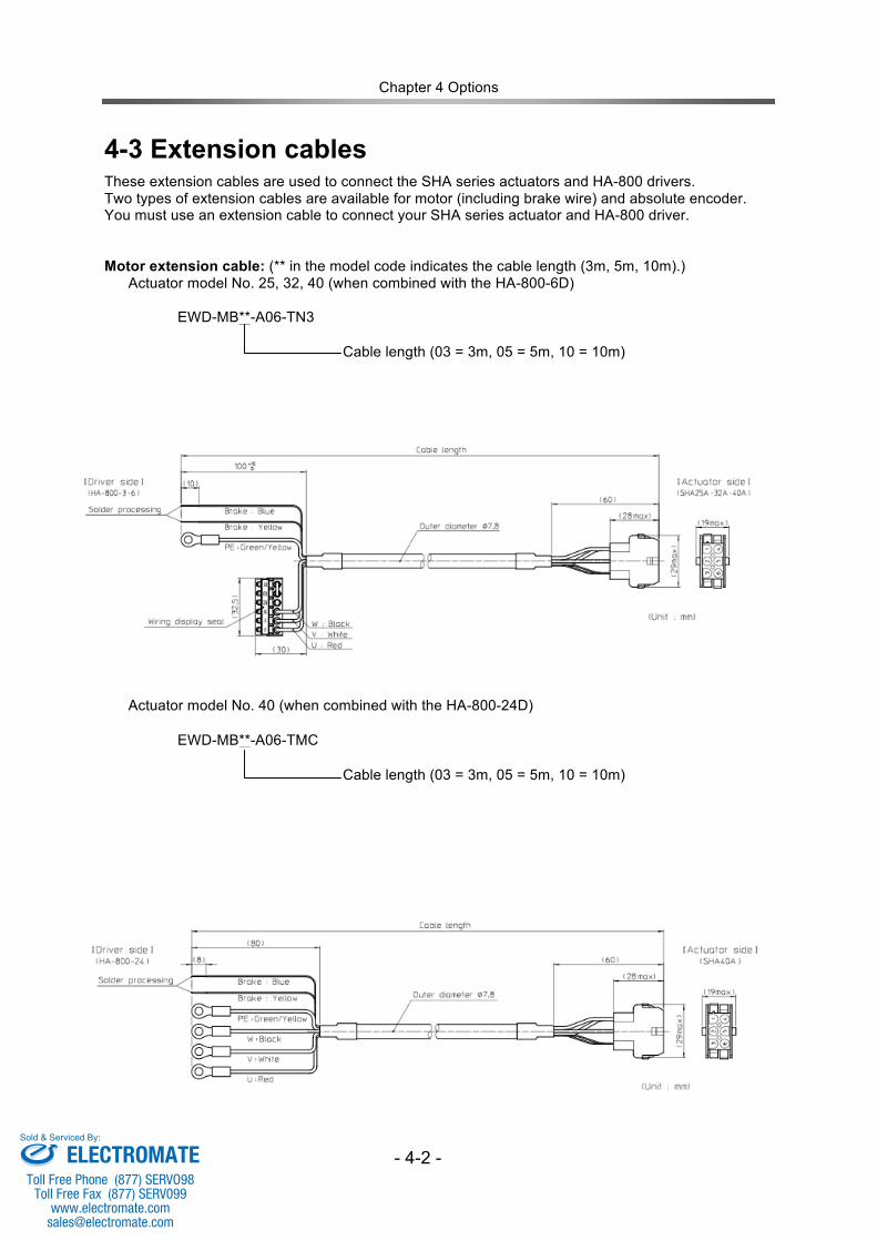
Chapter 4 Options
- 4-2 -
4-3 Extension cables These extension cables are used to connect the SHA series actuators and HA-800 drivers. Two types of extension cables are available for motor (including brake wire) and absolute encoder. You must use an extension cable to connect your SHA series actuator and HA-800 driver. Motor extension cable: (** in the model code indicates the cable length (3m, 5m, 10m).)
Actuator model No. 25, 32, 40 (when combined with the HA-800-6D)
EWD-MB**-A06-TN3
Cable length (03 = 3m, 05 = 5m, 10 = 10m)
Actuator model No. 40 (when combined with the HA-800-24D)
EWD-MB**-A06-TMC
Cable length (03 = 3m, 05 = 5m, 10 = 10m)
ELECTROMATEToll Free Phone (877) SERVO98
Toll Free Fax (877) SERV099www.electromate.com
Sold & Serviced By:
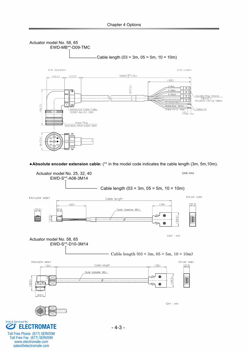
Chapter 4 Options
- 4-3 -
Actuator model No. 58, 65
EWD-MB**-D09-TMC
Cable length (03 = 3m, 05 = 5m, 10 = 10m)
●Absolute encoder extension cable: (** in the model code indicates the cable length (3m, 5m,10m).
Actuator model No. 25, 32, 40 EWD-S**-A08-3M14
Cable length (03 = 3m, 05 = 5m, 10 = 10m)
Actuator model No. 58, 65
EWD-S**-D10-3M14 Cable length (03 = 3m, 05 = 5m, 10 = 10m)
(Unit: mm)
ELECTROMATEToll Free Phone (877) SERVO98
Toll Free Fax (877) SERV099www.electromate.com
Sold & Serviced By:
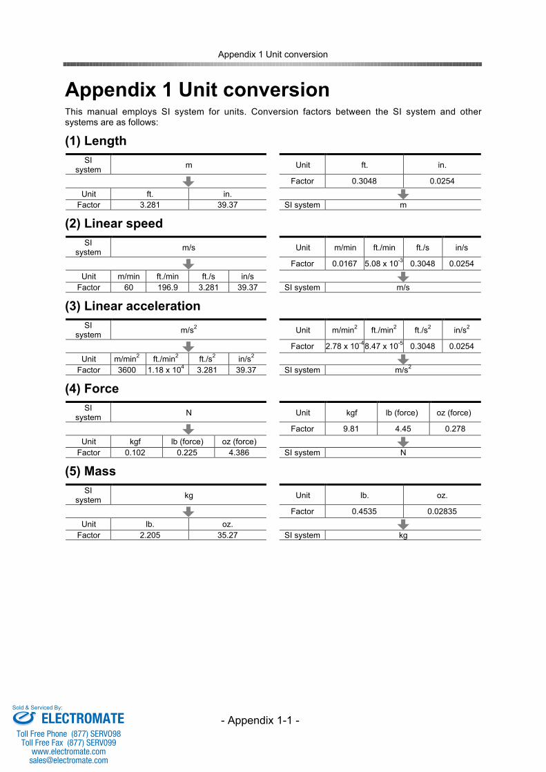
Appendix 1 Unit conversion
- Appendix 1-1 -
Appendix 1 Unit conversionThis manual employs SI system for units. Conversion factors between the SI system and othersystems are as follows:
(1) LengthSI
system m Unit ft. in.
Factor 0.3048 0.0254Unit ft. in.
Factor 3.281 39.37 SI system m
(2) Linear speedSI
system m/s Unit m/min ft./min ft./s in/s
Factor 0.0167 5.08 x 10⁻³ 0.3048 0.0254Unit m/min ft./min ft./s in/s
Factor 60 196.9 3.281 39.37 SI system m/s
(3) Linear accelerationSI
system m/s2 Unit m/min2 ft./min2 ft./s2 in/s2
Factor 2.78 x 10-48.47 x 10-5 0.3048 0.0254Unit m/min2 ft./min2 ft./s2 in/s2
Factor 3600 1.18 x 10⁴ 3.281 39.37 SI system m/s2
(4) ForceSI
system N Unit kgf lb (force) oz (force)
Factor 9.81 4.45 0.278Unit kgf lb (force) oz (force)
Factor 0.102 0.225 4.386 SI system N
(5) MassSI
system kg Unit lb. oz.
Factor 0.4535 0.02835Unit lb. oz.
Factor 2.205 35.27 SI system kg
ELECTROMATEToll Free Phone (877) SERVO98
Toll Free Fax (877) SERV099www.electromate.com
Sold & Serviced By:
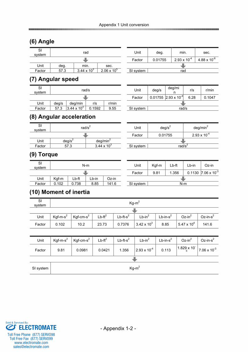
Appendix 1 Unit conversion
- Appendix 1-2 -
(6) AngleSI
system rad Unit deg. min. sec.
Factor 0.01755 2.93 x 10⁻⁴ 4.88 x 10⁻⁶
Unit deg. min. sec.Factor 57.3 3.44 x 10³ 2.06 x 10⁵ SI system rad
(7) Angular speedSI
system rad/s Unit deg/s deg/min r/s r/min
Factor 0.01755 2.93 x 10⁻⁴ 6.28 0.1047Unit deg/s deg/min r/s r/min
Factor 57.3 3.44 x 10³ 0.1592 9.55 SI system rad/s
(8) Angular accelerationSI
system rad/s2 Unit deg/s2 deg/min2
Factor 0.01755 2.93 x 10⁻⁴
Unit deg/s2 deg/min2
Factor 57.3 3.44 x 10³ SI system rad/s2
(9) TorqueSI
system N-m Unit Kgf-m Lb-ft Lb-in Oz-in
Factor 9.81 1.356 0.1130 7.06 x 10⁻³
Unit Kgf-m Lb-ft Lb-in Oz-inFactor 0.102 0.738 8.85 141.6 SI system N-m
(10) Moment of inertiaSI
system Kg-m2
Unit Kgf-m-s2 Kgf-cm-s2 Lb-ft2 Lb-ft-s2 Lb-in2 Lb-in-s2 Oz-in2 Oz-in-s2
Factor 0.102 10.2 23.73 0.7376 3.42 x 10³ 8.85 5.47 x 10⁴ 141.6
Unit Kgf-m-s2 Kgf-cm-s2 Lb-ft2 Lb-ft-s2 Lb-in2 Lb-in-s2 Oz-in2 Oz-in-s2
Factor 9.81 0.0981 0.0421 1.356 2.93 x 10⁻⁴ 0.113 1.829 x 10-
5 7.06 x 10⁻³
SI system Kg-m2
ELECTROMATEToll Free Phone (877) SERVO98
Toll Free Fax (877) SERV099www.electromate.com
Sold & Serviced By:
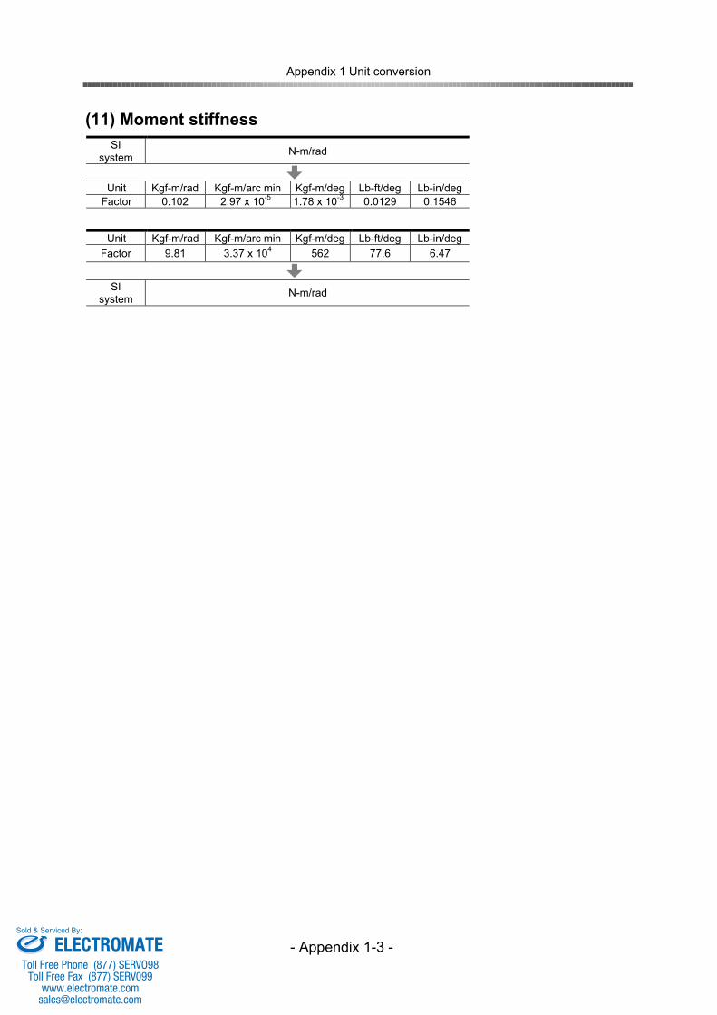
Appendix 1 Unit conversion
- Appendix 1-3 -
(11) Moment stiffnessSI
system N-m/rad
Unit Kgf-m/rad Kgf-m/arc min Kgf-m/deg Lb-ft/deg Lb-in/degFactor 0.102 2.97 x 10⁻⁵ 1.78 x 10⁻³ 0.0129 0.1546
Unit Kgf-m/rad Kgf-m/arc min Kgf-m/deg Lb-ft/deg Lb-in/degFactor 9.81 3.37 x 10⁴ 562 77.6 6.47
SIsystem N-m/rad
ELECTROMATEToll Free Phone (877) SERVO98
Toll Free Fax (877) SERV099www.electromate.com
Sold & Serviced By:
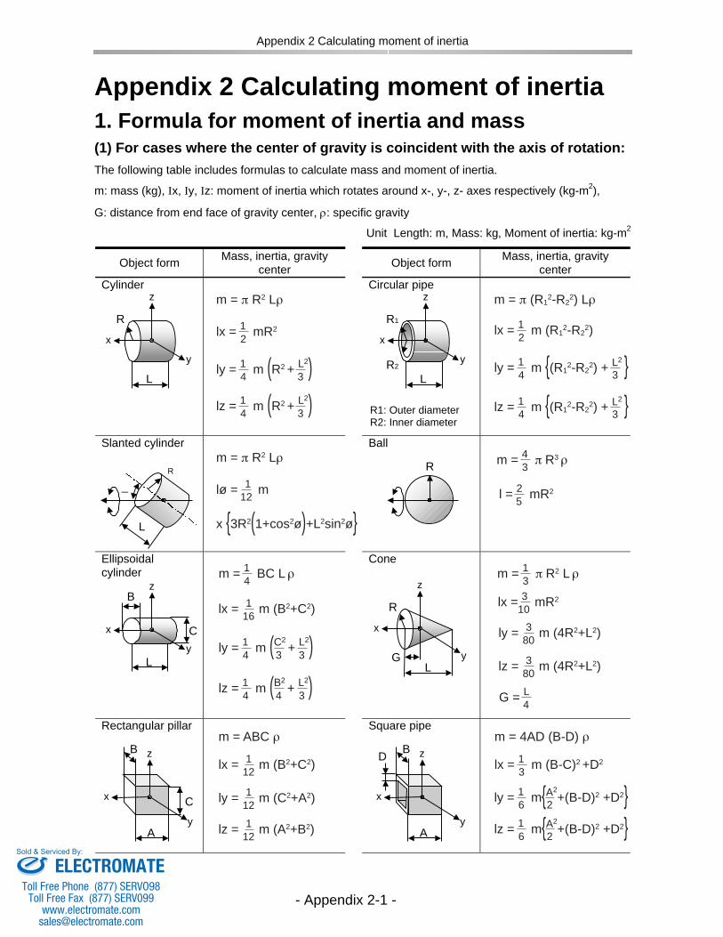
m = π R2 Lρ
lx = 1 mR22
ly = 1 m (R2 + L2)4 3
ly = 1 m (C2 + L
2)4 33
lz = 1 m (B2 + L
2)4 34
lz = 1 m (R2 + L2)4 3
m = π R2 Lρ
m = ABC ρ
x {3R2(1+cos2ø)+L2sin2ø}lø = 1 m12
m = π (R12-R2
2) Lρ
lx = 1 m (R12-R2
2)2
lx = 1 m (B2+C2)16
lx = 1 m (B2+C2)12
m = 4AD (B-D) ρ
lx = 1 m (B-C)2 +D23
ly = 1 m (C2+A2)12
lz = 1 m (A2+B2)12
ly = 3 m (4R2+L2)80
lz = 3 m (4R2+L2)80
ly = 1 m {(R12-R2
2) + L2 }4 3
lz = 1 m {(R12-R2
2) + L2 }4 3
ly = 1 m{A2+(B-D)2 +D2}6 2
lz = 1 m{A2+(B-D)2 +D2}6 2
m = 4 π R3 ρ3
G = L 4
m = 1 BC L ρ4 m = 1 π R2 L ρ3
l = 2 mR2 5
lx = 3 mR2 10
Appendix 2 Calculating moment of inertia
- Appendix 2-1 -
Appendix 2 Calculating moment of inertia
1. Formula for moment of inertia and mass(1) For cases where the center of gravity is coincident with the axis of rotation:
The following table includes formulas to calculate mass and moment of inertia.
m: mass (kg), Ix, Iy, Iz: moment of inertia which rotates around x-, y-, z- axes respectively (kg-m2),
G: distance from end face of gravity center, : specific gravity
Unit Length: m, Mass: kg, Moment of inertia: kg-m2
Object form Mass, inertia, gravitycenter Object form Mass, inertia, gravity
centerCylinder Circular pipe
Slanted cylinder Ball
Ellipsoidalcylinder
Cone
Rectangular pillar Square pipe
R
L
z
x
y
R1
LR2
z
x
y
R1: Outer diameterR2: Inner diameter
B
L
z
x
yC
R
L
z
x
yG
z
x
y
C
B
A
D B
A
z
x
y
R
L
_
R
ELECTROMATEToll Free Phone (877) SERVO98
Toll Free Fax (877) SERV099www.electromate.com
Sold & Serviced By:
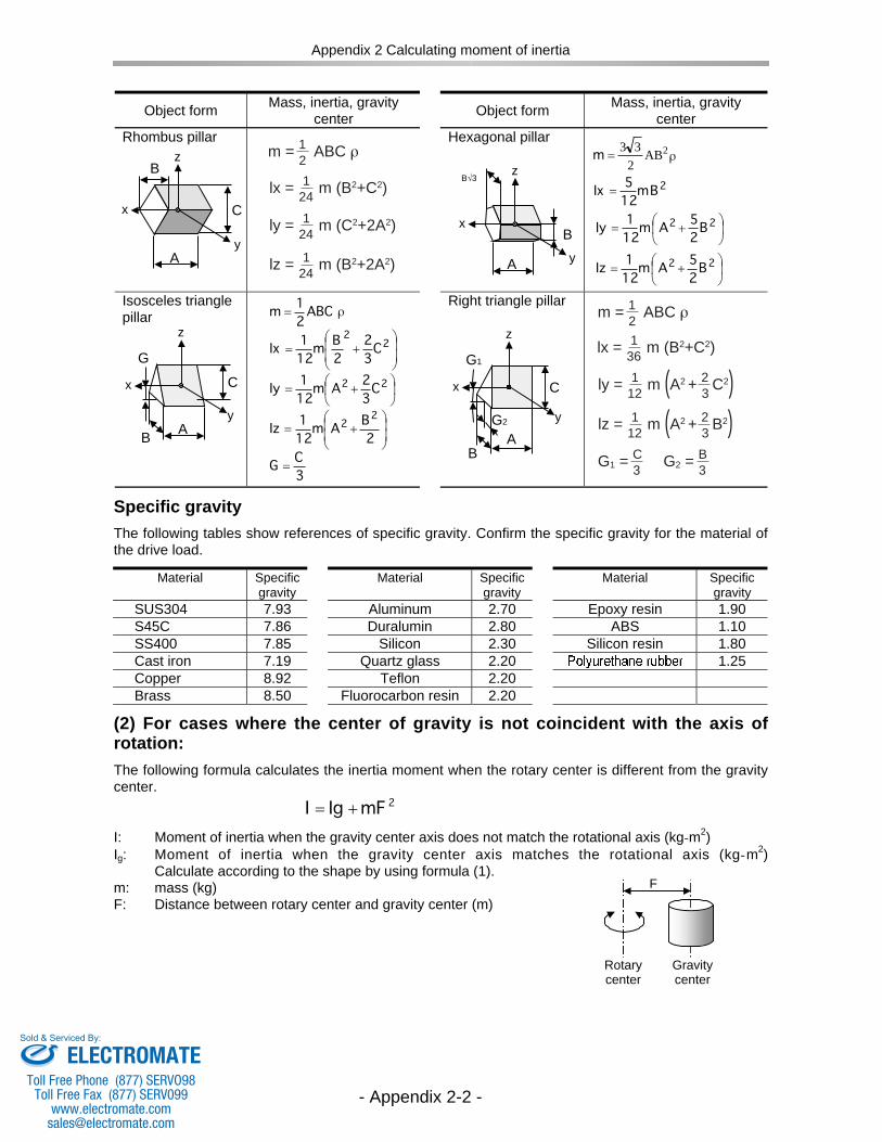
Appendix 2 Calculating moment of inertia
- Appendix 2-2 -
Object form Mass, inertia, gravitycenter Object form Mass, inertia, gravity
centerRhombus pillar Hexagonal pillar
Isosceles trianglepillar
Right triangle pillar
Specific gravity
The following tables show references of specific gravity. Confirm the specific gravity for the material ofthe drive load.
Material Specificgravity
Material Specificgravity
Material Specificgravity
SUS304 7.93 Aluminum 2.70 Epoxy resin 1.90S45C 7.86 Duralumin 2.80 ABS 1.10SS400 7.85 Silicon 2.30 Silicon resin 1.80Cast iron 7.19 Quartz glass 2.20 1.25Copper 8.92 Teflon 2.20Brass 8.50 Fluorocarbon resin 2.20
(2) For cases where the center of gravity is not coincident with the axis ofrotation:
The following formula calculates the inertia moment when the rotary center is different from the gravitycenter.
I: Moment of inertia when the gravity center axis does not match the rotational axis (kg-m2)Ig: Moment of inertia when the gravity center axis matches the rotational axis (kg-m2)
Calculate according to the shape by using formula (1).m: mass (kg)F: Distance between rotary center and gravity center (m)
Rotarycenter
Gravitycenter
F
ñABC2
1m =
+=2
2
C3
2
2
Bm
12
1Ix
+=22 C
3
2Am
12
1Iy
+=
2
BAm
12
1Iz
22
3
CG =
G
z
x
y
B A
CG1
z
x
y
BA
G2
C
z
x
y
C
A
B z
x
y
B
B 3
A
2Bm
12
5Ix =
+=22 B
2
5Am
12
1Iy
+=22
B2
5Am
12
1Iz
ñAB2
33 2=m
2mFIgI +=
m = 1 ABC ρ2
m = 1 ABC ρ2
ly = 1 m (A2 + 2 C2)12 3
lz = 1 m (A2 + 2 B2)12 3
lx = 1 m (B2+C2)24
lx = 1 m (B2+C2)36
ly = 1 m (C2+2A2)24
lz = 1 m (B2+2A2)24
G1 = C 3 G2 = B 3
ρ
ρ
ELECTROMATEToll Free Phone (877) SERVO98
Toll Free Fax (877) SERV099www.electromate.com
Sold & Serviced By:
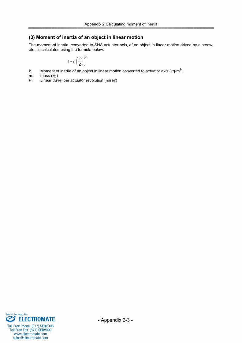
Appendix 2 Calculating moment of inertia
- Appendix 2-3 -
(3) Moment of inertia of an object in linear motionThe moment of inertia, converted to SHA actuator axis, of an object in linear motion driven by a screw,etc., is calculated using the formula below:
I: Moment of inertia of an object in linear motion converted to actuator axis (kg-m2)m: mass (kg)P: Linear travel per actuator revolution (m/rev)
2
2PmI
=
ELECTROMATEToll Free Phone (877) SERVO98
Toll Free Fax (877) SERV099www.electromate.com
Sold & Serviced By:
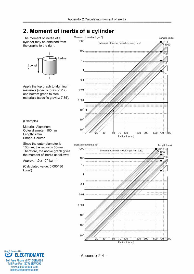
Appendix 2 Calculating moment of inertia
- Appendix 2-4 -
2. Moment of inertia of a cylinderThe moment of inertia of acylinder may be obtained fromthe graphs to the right.
Apply the top graph to aluminummaterials (specific gravity: 2.7)and bottom graph to steelmaterials (specific gravity: 7.85).
(Example)
Material: AluminumOuter diameter: 100mmLength: 7mmShape: Column
Since the outer diameter is100mm, the radius is 50mm.Therefore, the above graph givesthe moment of inertia as follows:
Approx. 1.9 x 10⁻⁴ kg-m2
(Calculated value: 0.000186kg-m2)
1000
100
10
1
0.1
0.01
0.001
10-4
10-5
10-6
10 100 100020 30 50 70 200 300 500 700
Moment of inertia (specific gravity: 7.85)
Inertia moment (kg-m2)
Radius R (mm)
Radius
1000
100
10
1
0.1
0.01
0.001
10-4
10-5
10-6
10 100 100020 30 50 70 200 300 500 700
Moment of inertia (specific gravity: 2.7)
Moment of inertia (kg-m2)
Radius R (mm)
Length (mm)
1000
100
10
Length (mm)
1000
100
10
LLength
Lengt
hLengt
hLengt
hLengt
hL1
1
ELECTROMATEToll Free Phone (877) SERVO98
Toll Free Fax (877) SERV099www.electromate.com
Sold & Serviced By:
The SHA series actuators warranty is as follows:Warranty periodSeller warrants that new and unused SHA actuator products sold by Seller shall be freefrom defects in material or workmanship for the shorter period of one (1) year from thedate of shipment or 2000 hours of operation.
Warranty termsEXCLUSIVE WARRANTY: THIS WARRANTY IS EXCLUSIVE AND IS IN LIEU OFANY OTHER WARRANTY, EXPRESS OR IMPLIED, INCLUDING, BUT NOT LIMITEDTO, ANY IMPLIED WARRANTY OF MERCHANTABILITY, FITNESS FOR APARTICULAR PURPOSE OR INFRINGEMENT.The Buyer shall promptly notify Seller in writing of any alleged defect. Warranty claimsmust be made by the Buyer who originally purchased the product from Seller. Thiswarranty is not transferrable to a third party.The Seller’s obligation under this warranty is limited to circumstances where the producthas been used under normal conditions for which it was designed and has beeninstalled, operated and maintained in accordance with the product specification andhandling instructions. This Warranty does not cover defects which were the result ofmisuse, improper installation or repair, alterations or modifications by the Buyer or anythird party, any natural disaster or any loss, damage, defect, claim or non-performanceresulting from or attributable to the Buyer’s specification.EXCLUSIVE REMEDY; LIMITATION OF DAMAGES: Seller's total liability and Buyer'sexclusive remedy under this contract is limited, at Seller's sole discretion , to eitherrepair, replace or return the purchase price paid, for any product, part or service whichis covered under this warranty and found by Seller to be defective. In no event shallSeller's liability exceed the contract price for the goods or services that are the basis forany covered claim. Even if the repair or replacement remedy should be deemed tohave failed of its essential purpose under Section 2-719 of the Uniform CommercialCode, Seller shall have no liability to Buyer for any consequential damages, including,but not limited to, lost profits, lost revenue, cost associated with removal, service, andinstallation of product, damage to other equipment, or liability for injury to a third party.
Warranty Period and Terms
ELECTROMATEToll Free Phone (877) SERVO98
Toll Free Fax (877) SERV099www.electromate.com
Sold & Serviced By:


