International Journal of Data Science and Analysis 2017; 3(6): 58-68 http://www.sciencepublishinggroup.com/j/ijdsa doi: 10.11648/j.ijdsa.20170306.11 ISSN: 2575-1883 (Print); ISSN: 2575-1891 (Online) Conference Paper Harmonics Reduction in a Wind Energy Conversion System with a Permanent Magnet Synchronous Generator Abdulhakim Nasr 1 , Mohammed El-Hawary 2 1 Department of Electrical Engineering, Collage of Engineering Technology, Huon, Libya 2 Department of Electrical & Computer Engineering, Dalhousie University Halifax, NS, Canada Email address: To cite this article: Abdulhakim Nasr, Mohammed El-Hawary. Harmonics Reduction in a Wind Energy Conversion System with a Permanent Magnet Synchronous Generator. International Journal of Data Science and Analysis. Vol. 3, No. 6, 2017, pp. 58-68. doi: 10.11648/j.ijdsa.20170306.11 Received: September 8, 2017; Accepted: October 10, 2017; Published: November 8, 2017 Abstract: This paper is mainly doing simulation using Matlab to filter harmonics which are found in a Permanent Magnet Synchronous Generator (PMSG) Wind Energy Conversion System (WECS) connected to a three-phase load through a full converter (AC/DC/AC). Harmonics are caused by the converter system. To reduce these harmonics, an effective filter is needed. There are two types of filters that are usually used, active and passive filters. Among the types of passive filters are band pass which block lower harmonics orders such as 5 th , 7 th , 11 th , and 13 th , and high pass filters which are responsible to filter higher harmonics such as 24 th . So, we use two stages of harmonic filtering. The first stage includes a c- type high pass filter (for lower orders), a double – tuned filter (for 11 th and 13 th ) and high pass filter (for higher orders). Secondly, this stage includes a single – tuned filter instead of C- type filter with keeping the other filters. We applied Fast Fourier Transform (FFT) to determine the harmonics and purposes. In this thesis, we investigate and analyse the level of harmonic content of two AC/DC converters working at different wind speeds. Our findings indicate significant improvements in Total Harmonic Distortion (THD) with best results in the second method. Keywords: Wind, Turbine, Power, Harmonics, Filter 1. Introduction The achievement of wind energy has grown in recently years [1]. According to the Global Wind Energy Council (GWEC), the capacity of installed wind energy has grown up to 19% in 2012 to 282 GW. The total installed wind capacity in the world by the end of 2012 is 44.711 GW [2]. With the remarkable progress to the use of wind power, the wind energy conversion system has been installed in many countries. However, the generated power from the wind is variable due to the variations in wind speed. Wind turbine concepts are divided into four types: first, fixed – speed wind turbine, secondly, variable speed wind turbine with variable rotor resistance, the third is a variable speed wind turbine with partial – scale power converter, and lastly, variable speed wind turbine with full – scale power converter. In fixed speed turbine, the generator used is mostly a Squirrel Cage Induction Generator (SCIG) and it is connected straightway to the grid through a transformer. The second configuration is connected to an Optislip Induction Generator (OSIG). One advantage of this type is no need of slip – rings due to the control system in the rotor windings. Thirdly, the most common generator used with this type is a Doubly – Fed Induction Generator (DFIG). Lastly, it is a variable speed wind turbine concept with full – scale power converter. There are two possible generators that could be used in this configuration. They are Permanent Magnet Synchronous Generator (PMSG) and (SCIG) [3]. Power electronic is an important part in wind turbine systems [4]. It uses to integrate the variable speed wind power generation to improve the efficiency and performance to the system. The disadvantages of using power electronics are increasing the cost and power losses. Moreover, they produce harmonics in WECS, such as rising electrical losses and the
Transcript
International Journal of Data Science and Analysis 2017; 3(6): 58-68
http://www.sciencepublishinggroup.com/j/ijdsa
doi: 10.11648/j.ijdsa.20170306.11
ISSN: 2575-1883 (Print); ISSN: 2575-1891 (Online)
Conference Paper
Harmonics Reduction in a Wind Energy Conversion System with a Permanent Magnet Synchronous Generator
Abdulhakim Nasr1, Mohammed El-Hawary
2
1Department of Electrical Engineering, Collage of Engineering Technology, Huon, Libya 2Department of Electrical & Computer Engineering, Dalhousie University Halifax, NS, Canada
Email address:
To cite this article: Abdulhakim Nasr, Mohammed El-Hawary. Harmonics Reduction in a Wind Energy Conversion System with a Permanent Magnet
Synchronous Generator. International Journal of Data Science and Analysis. Vol. 3, No. 6, 2017, pp. 58-68. doi: 10.11648/j.ijdsa.20170306.11
Received: September 8, 2017; Accepted: October 10, 2017; Published: November 8, 2017
Abstract: This paper is mainly doing simulation using Matlab to filter harmonics which are found in a Permanent Magnet
Synchronous Generator (PMSG) Wind Energy Conversion System (WECS) connected to a three-phase load through a full
converter (AC/DC/AC). Harmonics are caused by the converter system. To reduce these harmonics, an effective filter is needed.
There are two types of filters that are usually used, active and passive filters. Among the types of passive filters are band pass
which block lower harmonics orders such as 5th
, 7th
, 11th
, and 13th
, and high pass filters which are responsible to filter higher
harmonics such as 24th
. So, we use two stages of harmonic filtering. The first stage includes a c- type high pass filter (for lower
orders), a double – tuned filter (for 11th
and 13th
) and high pass filter (for higher orders). Secondly, this stage includes a single –
tuned filter instead of C- type filter with keeping the other filters. We applied Fast Fourier Transform (FFT) to determine the
harmonics and purposes. In this thesis, we investigate and analyse the level of harmonic content of two AC/DC converters
working at different wind speeds. Our findings indicate significant improvements in Total Harmonic Distortion (THD) with best
results in the second method.
Keywords: Wind, Turbine, Power, Harmonics, Filter
1. Introduction
The achievement of wind energy has grown in recently
years [1]. According to the Global Wind Energy Council
(GWEC), the capacity of installed wind energy has grown up
to 19% in 2012 to 282 GW. The total installed wind capacity
in the world by the end of 2012 is 44.711 GW [2].
With the remarkable progress to the use of wind power,
the wind energy conversion system has been installed in
many countries. However, the generated power from the
wind is variable due to the variations in wind speed. Wind
turbine concepts are divided into four types: first, fixed –
with variable rotor resistance, the third is a variable speed
wind turbine with partial – scale power converter, and lastly,
variable speed wind turbine with full – scale power converter.
In fixed speed turbine, the generator used is mostly a Squirrel
Cage Induction Generator (SCIG) and it is connected
straightway to the grid through a transformer. The second
configuration is connected to an Optislip Induction
Generator (OSIG). One advantage of this type is no need of
slip – rings due to the control system in the rotor windings.
Thirdly, the most common generator used with this type is a
Doubly – Fed Induction Generator (DFIG). Lastly, it is a
variable speed wind turbine concept with full – scale power
converter. There are two possible generators that could be
used in this configuration. They are Permanent Magnet
Synchronous Generator (PMSG) and (SCIG) [3].
Power electronic is an important part in wind turbine
systems [4]. It uses to integrate the variable speed wind power
generation to improve the efficiency and performance to the
system. The disadvantages of using power electronics are
increasing the cost and power losses. Moreover, they produce
harmonics in WECS, such as rising electrical losses and the
59 Abdulhakim Nasr and Mohammed El-Hawary: Harmonics Reduction in a Wind Energy Conversion
System with a Permanent Magnet Synchronous Generator
low quality of the output power [5]. The active filters could be
a choice to reduce those harmonics as well as passive filters.
But, in this study, we will use active filters. In this type of
filters, based on the output signals the essential high pass filter
is connected to the lines to decrease the harmonics in the
system.
1.1. Harmonics in Wind Turbine Systems
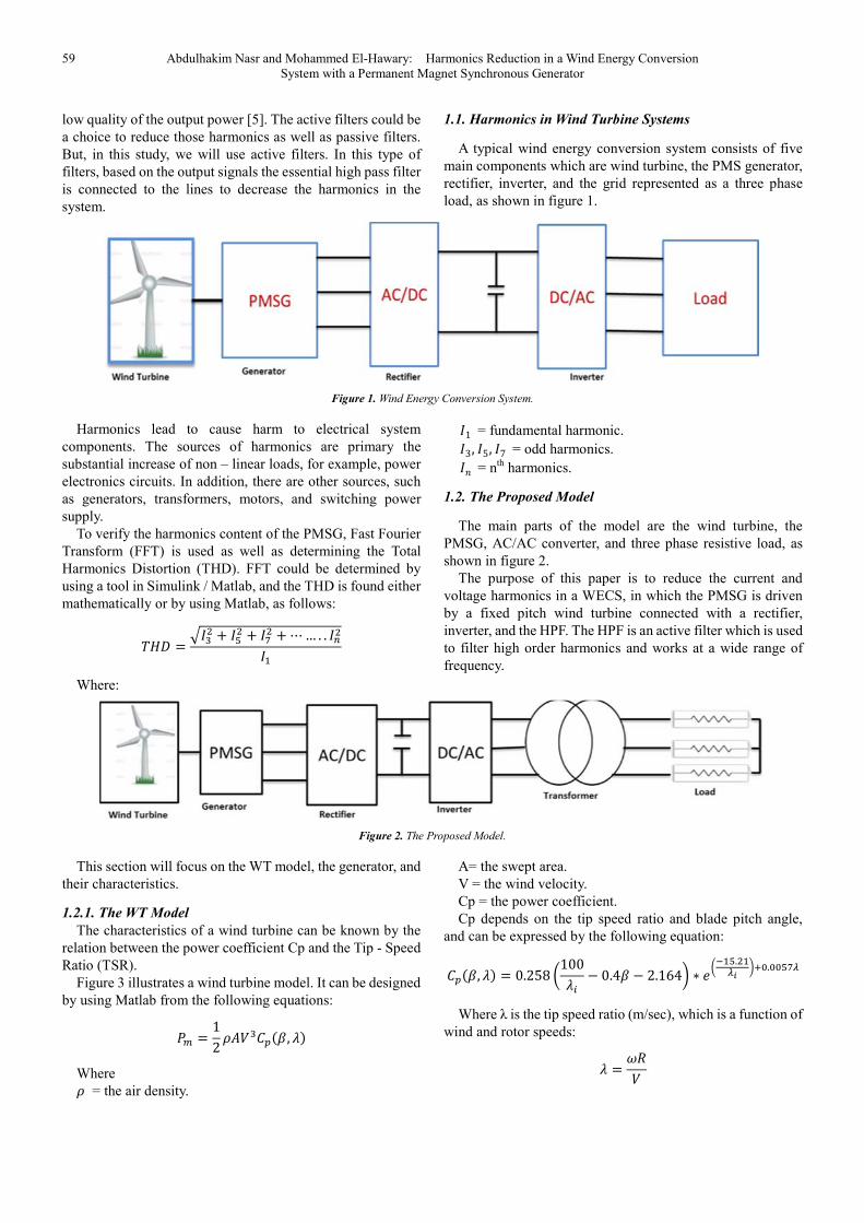
A typical wind energy conversion system consists of five
main components which are wind turbine, the PMS generator,
rectifier, inverter, and the grid represented as a three phase
load, as shown in figure 1.
Figure 1. Wind Energy Conversion System.
Harmonics lead to cause harm to electrical system
components. The sources of harmonics are primary the
substantial increase of non – linear loads, for example, power
electronics circuits. In addition, there are other sources, such
as generators, transformers, motors, and switching power
supply.
To verify the harmonics content of the PMSG, Fast Fourier
Transform (FFT) is used as well as determining the Total
Harmonics Distortion (THD). FFT could be determined by
using a tool in Simulink / Matlab, and the THD is found either
mathematically or by using Matlab, as follows:
⋯… . .
Where:
1 = fundamental harmonic.
3, 5, 7 = odd harmonics.
= nth
harmonics.
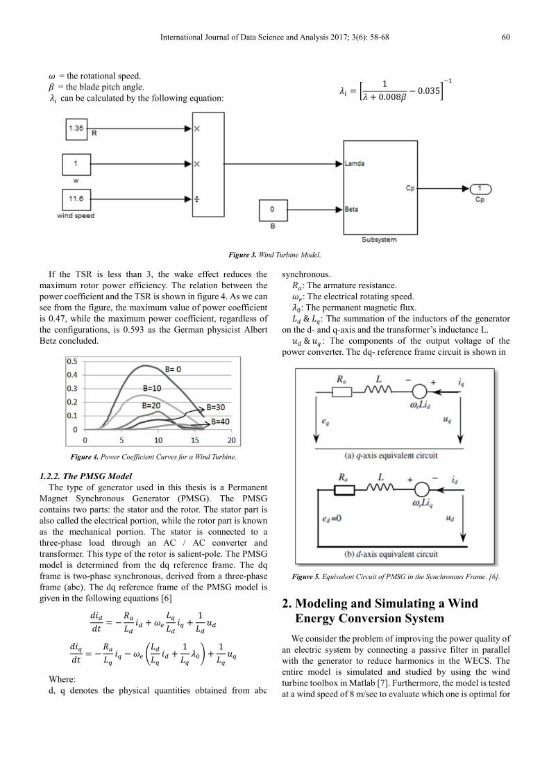
1.2. The Proposed Model
The main parts of the model are the wind turbine, the
PMSG, AC/AC converter, and three phase resistive load, as
shown in figure 2.
The purpose of this paper is to reduce the current and
voltage harmonics in a WECS, in which the PMSG is driven
by a fixed pitch wind turbine connected with a rectifier,
inverter, and the HPF. The HPF is an active filter which is used
to filter high order harmonics and works at a wide range of
frequency.
Figure 2. The Proposed Model.
This section will focus on the WT model, the generator, and
their characteristics.
1.2.1. The WT Model
The characteristics of a wind turbine can be known by the
relation between the power coefficient Cp and the Tip - Speed
Ratio (TSR).
Figure 3 illustrates a wind turbine model. It can be designed
by using Matlab from the following equations:
12 , !"
Where = the air density.
A= the swept area.
V = the wind velocity.
Cp = the power coefficient.
Cp depends on the tip speed ratio and blade pitch angle,
and can be expressed by the following equation:
, !" 0.258 %100!& ' 0.4 ' 2.164* ∗ ,%-../ *01.11.
Where λ is the tip speed ratio (m/sec), which is a function of
wind and rotor speeds:
! 23
International Journal of Data Science and Analysis 2017; 3(6): 58-68 60
2 = the rotational speed. = the blade pitch angle. !4 can be calculated by the following equation: !& 5 1
! 0.008 ' 0.0356-
Figure 3. Wind Turbine Model.
If the TSR is less than 3, the wake effect reduces the
maximum rotor power efficiency. The relation between the
power coefficient and the TSR is shown in figure 4. As we can
see from the figure, the maximum value of power coefficient
is 0.47, while the maximum power coefficient, regardless of
the configurations, is 0.593 as the German physicist Albert
Betz concluded.
Figure 4. Power Coefficient Curves for a Wind Turbine.
1.2.2. The PMSG Model
The type of generator used in this thesis is a Permanent
Magnet Synchronous Generator (PMSG). The PMSG
contains two parts: the stator and the rotor. The stator part is
also called the electrical portion, while the rotor part is known
as the mechanical portion. The stator is connected to a
three-phase load through an AC / AC converter and
transformer. This type of the rotor is salient-pole. The PMSG
model is determined from the dq reference frame. The dq
frame is two-phase synchronous, derived from a three-phase
frame (abc). The dq reference frame of the PMSG model is
given in the following equations [6]
74879 '3:;8 48 2<;=;8 4=
1;8 >8
74=79 '3:;= 4= ' 2< ?;8;= 48 1;= !1@
1;= >=
Where:
d, q denotes the physical quantities obtained from abc
synchronous. 3A: The armature resistance. 2,: The electrical rotating speed. !0: The permanent magnetic flux. ;7&;D: The summation of the inductors of the generator
on the d- and q-axis and the transformer’s inductance L. >7&>D : The components of the output voltage of the
power converter. The dq- reference frame circuit is shown in
Figure 5. Equivalent Circuit of PMSG in the Synchronous Frame. [6].
2. Modeling and Simulating a Wind
Energy Conversion System
We consider the problem of improving the power quality of
an electric system by connecting a passive filter in parallel
with the generator to reduce harmonics in the WECS. The
entire model is simulated and studied by using the wind
turbine toolbox in Matlab [7]. Furthermore, the model is tested
at a wind speed of 8 m/sec to evaluate which one is optimal for
61 Abdulhakim Nasr and Mohammed El-Hawary: Harmonics Reduction in a Wind Energy Conversion
System with a Permanent Magnet Synchronous Generator
operation. We will study the system performance at three
levels of wind speeds and compare the generator output
voltage and current waveforms in three cases. Figure 6 shows
the distributed generation based on a stand-alone wind energy
conversion system (WECS) including PMSG is simulated,
with the model. This is an 8 MW wind turbine connected to a
PMSG through an AC/DC/AC converter and 575/100 V
transformer to a three-phase resistive load (300 Ω).
Figure 6. The Simulated Model.
We used two different AC/DC/AC converter which are
diode rectifier and thyristor rectifier. In the model, which
has been simulated in a normal situation, we find that
there are harmonics in the generator through the output
voltage and current waves. The harmonics orders found in
this system are mostly 3rd
, 5th
, 7th
, 11th
, and 24th
. So, we try
to improve the Total Harmonic Distortion (THD) by
adding a three-phase filter in parallel with the generator
side through a circuit breaker.
2.1. The Three-Phase Harmonic Filter
The three-phase harmonic filter is built of RLC
elements, with resistance, inductance, and capacitance
values determined from the filter type and the following
parameters:
1. Reactive power at nominal voltage.
2. Tuning frequencies.
3. Quality factor. (The quality factor is a measure of
the sharpness of the tuning frequency, determined by
the resistance value.)
2.2. The Harmonics Filtering Method
The harmonics found in this system fluctuate between
the 3rd
and the 24th
. Therefore, our approach is to try two
different stages of harmonic filters to connect to the
generator. The first stage contains double-tuned filters,
C-type high-pass filters, and high-pass filters (HPF), due
to their abilities to work in these frequency ranges.
Secondly, three filters are connected in parallel to the
generator. They are single – tuned, double – tuned and
high – pass filters. We will use those combinations with
diode rectifier and thyristor rectifier converters. Before
selecting the filter, the impedance vs. frequency of the
harmonics is determined. This is shown in Figure 7. As
can be seen, the impedance of the three-phase filters at the
system frequency (60 Hz) is 0.001 ohms with '900" phase angle. The following equation can be used to
compute the total reactive power provided by filters [8].
FG HG
where:
FI is the total reactive power of the filters.
V is the phase-to-phase voltage of the generator, equal
to 730 volts.
HI is capacitor reactance at a fundamental frequency
(60 Hz)
In order to minimize the total harmonic distortion, we
evaluated the best parameters. The filter designed in this
thesis consists of the following four components:
1. One capacitor bank.
2. One high-pass filter tuned to the 24th
harmonic order.
3. One double-tuned filter of the 11/13th
harmonics
orders.
4. One C-type high-pass filter tuned to the 3rd
harmonic
order.
Each component provides a negative reactive power, as
follows:
FI 2HI
73020.001 532.9JKAL
Assuming four identical capacitors, each will supply
133.22 Mvar (we will use a Single – tuned filter instead of C-
type high pass in case 3).
So, the final setting of filters is
1. One capacitor bank of 133.22 Mvar.
2. One C-type high-pass filter (133.22 Mvar).
3. One double-tuned filter (133.22 Mvar).
4. One high-pass filter (133.22 Mvar).
5. Single – tuned filter (133.22 Mvar).
International Journal of Data Science and Analysis 2017; 3(6): 58-68 62
Figure 7. Frequency-Domain Response.
Next, we will calculate the parameters of each type of
Reactive power (Mvar) 133.22 Tuning frequencies (Hz) [5*60] 5
The quality factor F MNO 2
We discuss three cases of harmonics filtering. The first
case is to simulate the system without having three phase
filters. Secondly, we simulate the system with having one
stage of three phase filters. The third case is to simulate the
system with having two stages of three phase filters. The
output voltage and current generator signals are presented
and analyzed. Results are compared and discussed using two
different converters.
3. The Generator Voltage and Current
Outputs
3.1. Using Diode Rectifier Converter
Figure 8-a shows the distorted generator voltage output
due to AC/DC diode rectifier. It appears as if there are many
harmonics passing through the generator. After deploying
the filters, the voltage harmonics are considered a sine wave
form. Figure 8-b illustrates the improved generator voltage
output due to AC/DC diode rectifier. The simulated THD
for the improved voltage waveform decreased from 4.17%
to 0.79%. Figure 8-c illustrates the improved generator
voltage output after placing two stages of filters. The total
harmonic distortion of the sine wave voltage signal reduced
from 0.79% to 0.52%.
a. case 1.
63 Abdulhakim Nasr and Mohammed El-Hawary: Harmonics Reduction in a Wind Energy Conversion
System with a Permanent Magnet Synchronous Generator
b. case 2.
c. case 3.
Figure 8. The Generator Voltage Output for the Three Cases Using Diode Rectifier.
Figure 9-a shows the distorted generator current output. It
appears as if there are many harmonics passing through the
generator. After placing the filters, the current harmonics are
considered a sine wave form. Figure 9-b illustrates the
improved generator voltage output due to AC/DC diode
rectifier. The simulated THD for the improved voltage
waveform decreased from 7.55% to 0.75%. Figure 9-c
illustrates the improved generator voltage output after placing
two stages of filters. The total harmonic distortion of the sine
wave voltage signal reduced from 0.75% to 0.5%.
a. case 1.
b. case 2.
c. case 3.
Figure 9. The Generator Current Output for the Three Cases Using Diode Rectifier.
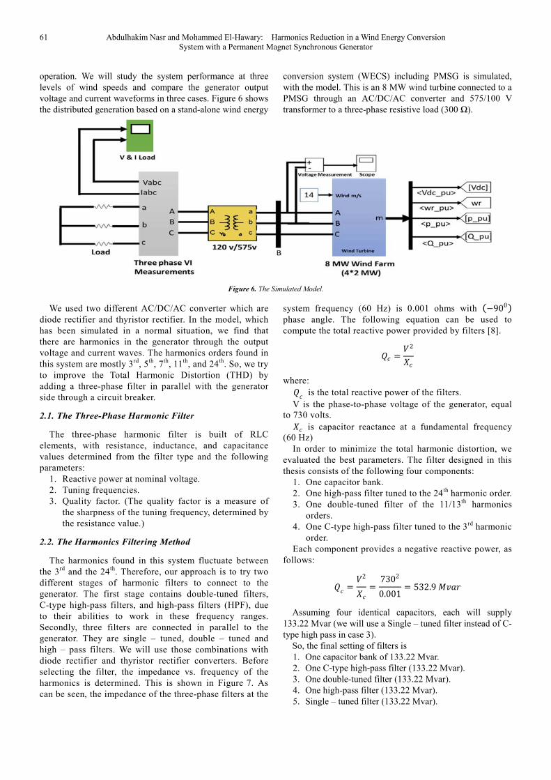
3.2. Using Thyristor Rectifier Converter
Figure 10-a illustrates the distorted generator phase A
voltage output due to AC/DC thyristor rectifier. As shown in
the figure, it is slightly distorted. Based on this distorted signal,
there appear to be much harmonic contents passing through
the generator. Figure 10-b shows the improved generator
phase A voltage output after placing three phase filters, As we
can see from the figure, it is significantly developed. The
simulated THD for the improved voltage waveform decreased
from 11.16% to 0.63%. We get improvements in THVD for
this method comparing with using diode rectifier in this case.
International Journal of Data Science and Analysis 2017; 3(6): 58-68 64
Figure 10-c illustrates the improved generator phase A voltage
output after placing another stage of three phase filters. It is
significantly developed. The simulated THD for the improved
voltage waveform decreased from 0.63% to 0.62%. We get
better results in both THVD for this method comparing with
the second one.
a. case 1.
b. case 2.
c. case 3.
Figure 10. The Generator Voltage Output for the Three Cases Using Thyristor Rectifier.
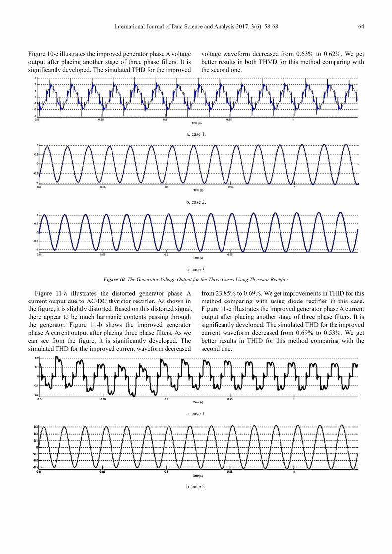
Figure 11-a illustrates the distorted generator phase A
current output due to AC/DC thyristor rectifier. As shown in
the figure, it is slightly distorted. Based on this distorted signal,
there appear to be much harmonic contents passing through
the generator. Figure 11-b shows the improved generator
phase A current output after placing three phase filters, As we
can see from the figure, it is significantly developed. The
simulated THD for the improved current waveform decreased
from 23.85% to 0.69%. We get improvements in THID for this
method comparing with using diode rectifier in this case.
Figure 11-c illustrates the improved generator phase A current
output after placing another stage of three phase filters. It is
significantly developed. The simulated THD for the improved
current waveform decreased from 0.69% to 0.53%. We get
better results in THID for this method comparing with the
second one.
a. case 1.
b. case 2.
65 Abdulhakim Nasr and Mohammed El-Hawary: Harmonics Reduction in a Wind Energy Conversion
System with a Permanent Magnet Synchronous Generator
c. case 3.
Figure 11. The Generator Current Output for the Three Cases Using Thyristor Rectifier.
4. Harmonics Contents of the Generator
Voltage and Current
4.1. Using Diode Rectifier
To find the harmonics, the Fast Fourier Transform is
applied to these signals by using a Matlab function of FFT to
calculate the order harmonics and the THD. The amplitudes of
the 5th and 7th harmonics are 4.3% and 4.1% of the
fundamental component, respectively. We can observe from
the figures that the harmonic orders of the 5th, 7th, 11th, and
13th are significant. The total harmonic distortion obtained
for the output voltage is THD=4.17%. Therefore, we attempt
to lower these percentages by using a three-phase harmonic
filter. After we place one stage of filters, we got better THD
which is 0.79%. And 0.52% when we use two stages of
filters. Harmonics voltage content of the three cases is shown
in Figure 12.
a. case 1.
b. case 2.
c. case 3.
Figure 12. Harmonics Content of the Generator Output Voltage When Using
Diode Converter.
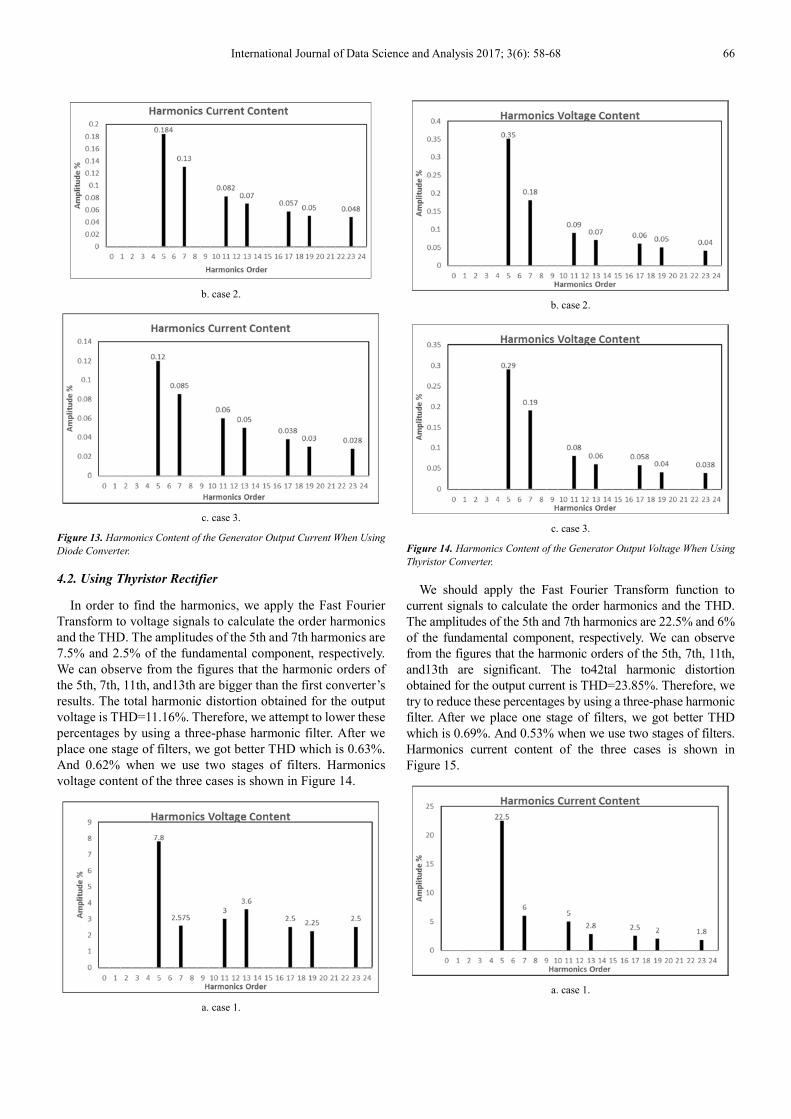
We find the harmonics by using the Fast Fourier Transform
function to current signals to calculate the order harmonics
and the THD. The amplitudes of the 5th and 7th harmonics are
16.5% and 11% of the fundamental component, respectively.
We can observe from the figures that the harmonic orders of
the 5th, 7th, 11th, and13th are significant. The total harmonic
distortion obtained for the output current is THD=7.55%.
Therefore, we try to decrease these percentages by using a
three-phase harmonic filter. After we place one stage of filters,
we got better THD which is 0.75%. And 0.50% when we use
two stages of filters.
Harmonics current content of the three cases is shown in
Figure 13.
a. case 1.
International Journal of Data Science and Analysis 2017; 3(6): 58-68 66
b. case 2.
c. case 3.
Figure 13. Harmonics Content of the Generator Output Current When Using
Diode Converter.
4.2. Using Thyristor Rectifier
In order to find the harmonics, we apply the Fast Fourier
Transform to voltage signals to calculate the order harmonics
and the THD. The amplitudes of the 5th and 7th harmonics are
7.5% and 2.5% of the fundamental component, respectively.
We can observe from the figures that the harmonic orders of
the 5th, 7th, 11th, and13th are bigger than the first converter’s
results. The total harmonic distortion obtained for the output
voltage is THD=11.16%. Therefore, we attempt to lower these
percentages by using a three-phase harmonic filter. After we
place one stage of filters, we got better THD which is 0.63%.
And 0.62% when we use two stages of filters. Harmonics
voltage content of the three cases is shown in Figure 14.
a. case 1.
b. case 2.
c. case 3.
Figure 14. Harmonics Content of the Generator Output Voltage When Using
Thyristor Converter.
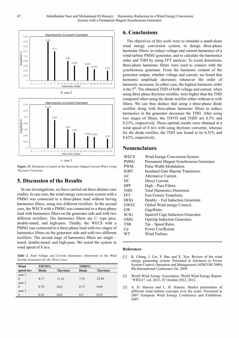
We should apply the Fast Fourier Transform function to
current signals to calculate the order harmonics and the THD.
The amplitudes of the 5th and 7th harmonics are 22.5% and 6%
of the fundamental component, respectively. We can observe
from the figures that the harmonic orders of the 5th, 7th, 11th,
and13th are significant. The to42tal harmonic distortion
obtained for the output current is THD=23.85%. Therefore, we
try to reduce these percentages by using a three-phase harmonic
filter. After we place one stage of filters, we got better THD
which is 0.69%. And 0.53% when we use two stages of filters.
Harmonics current content of the three cases is shown in
Figure 15.
a. case 1.
67 Abdulhakim Nasr and Mohammed El-Hawary: Harmonics Reduction in a Wind Energy Conversion
System with a Permanent Magnet Synchronous Generator
b. case 2.
c. case 3.
Figure 15. Harmonics Content of the Generator Output Current When Using
Thyristor Converter.
5. Discussion of the Results
In our investigations, we have carried out three distinct case
studies. In one case, the wind energy conversion system with a
PMSG was connected to a three-phase load without having
harmonics filters, using two different rectifiers. In the second
case, the WECS with a PMSG was connected to a three-phase
load with harmonics filters on the generator side and with two
different rectifiers. The harmonics filters are C- type pass,
double-tuned, and high-pass. Thirdly, the WECS with a
PMSG was connected to a three-phase load with two stages of
harmonics filters on the generator side and with two different
rectifiers. The second stage of harmonics filters are single –
tuned, double-tuned, and high-pass. We tested the system in
wind speed of 8 m/s.
Table 2. Total Voltage and Current Harmonics Distortions in the Wind
Turbine Generator for the Three Cases.
Wind
speed m/s
THVD% THID%
Diode Thyristor Diode Thyristor
case 1
8 4.17 11.16 7.55 23.85
case 2
8 0.79 0.63 0.75 0.69
case 3
8 0.52 0.62 0.5 0.53
6. Conclusions
The objectives of this work were to simulate a stand-alone
wind energy conversion system, to design three-phase
harmonic filters, to reduce voltage and current harmonics of a
wind turbine PMSG generator, and to calculate the harmonics
order and THD by using FFT analysis. To avoid distortions,
three-phase harmonic filters were used to connect with the
synchronous generator. From the harmonic content of the
generator output, whether voltage and current, we found that
harmonic amplitude decreases whenever the order of
harmonic increases. In either case, the highest harmonic order
is the 5th
. The obtained THD of both voltage and current, when
using three phase thyristor rectifier, were higher than the THD
computed when using the diode rectifier either without or with
filters. We can thus deduce that using a three-phase diode
rectifier along with three-phase harmonic filters to reduce
harmonics in the generator decreases the THD. After using
two stages of filters, the THVD and THID are 0.5% and
0.53%, respectively. These optimal results were obtained at a
wind speed of 8 m/s with using thyristor converter, whereas
for the diode rectifier, the THD was found to be 0.52% and
0.62%, respectively.
Nomenclature
WECS Wind Energy Conversion System.
PMSG Permanent Magnet Synchronous Generator.
PWM Pulse Width Modulation.
IGBT Insulated Gate Bipolar Transistors.
AC Alternative Current.
DC Direct Current.
HPF High – Pass Filters.
THD Total Harmonics Distortion.
FFT Fast Fourier Transform.
DFIG Doubly – Fed Induction Generator.
GWEC Global Wind energy Council.
GW GigaWatts.
SCIG Squirrel Cage Induction Generator.
OSIG Optislip Induction Generator.
TSR Tip – Speed Ratio.
Cp Power Coefficient.
WT Wind Turbine.
References
[1] K. Cheng, J. Lin, Y. Bao and X. Xue. Review of the wind energy generating system. Presented at Advances in Power System Control, Operation and Management (APSCOM 2009), 8th International Conference On. 2009.
[2] World Wind Energy Association, World Wind Energy Report, "WWEA", vol. 2013, 07 October 2012, 2012.
[3] A. D. Hansen and L. H. Hansen. Market penetration of different wind turbine concepts over the years. Presented at 2007 European Wind Energy Conference and Exhibition. 2007.
International Journal of Data Science and Analysis 2017; 3(6): 58-68 68
[4] Z. Chen, J. M. Guerrero and F. Blaabjerg. A review of the state of the art of power electronics for wind turbines. Power Electronics, IEEE Transactions On 24(8), pp. 1859-1875. 2009.
[5] A. Hoseinpour, S. Masoud Barakati and R. Ghazi. Harmonic reduction in wind turbine generators using a shunt active filter based on the proposed modulation technique. International Journal of Electrical Power & Energy Systems 43(1), pp. 1401-1412. 2012.
[6] M. Yin, G. Li, M. Zhou and C. Zhao. Modeling of the wind
turbine with a permanent magnet synchronous generator for integration. Presented at Power Engineering Society General Meeting, 2007. IEEE. 2007.
[7] Wind Farm - Synchronous Generator and Full Scale Converter (Type 4) Average Model, Http://www. Mathworks. com/help/physmod/powersys/examples/wind-Farm-Synchronous-Generator-and-Full-Scale-Converter-Type-4-Average-Model.