Page 1
HASH GRAPH BASED KEY PREDISTRIBUTION SCHEME FOR MOBILE
AND MULTIPHASE WIRELESS SENSOR NETWORKS
by
SALİM SARIMURAT
Submitted to the Graduate School of Engineering and Natural Sciences
in partial fulfillment of
the requirements for the degree of
Master of Science
Sabancı University
August 2013
brought to you by COREView metadata, citation and similar papers at core.ac.uk
provided by Sabanci University Research Database
Page 3
iii
© Salim Sarımurat 2013
All Rights Reserved
Page 4
iv
HASH GRAPH BASED KEY PREDISTRIBUTION SCHEME FOR MOBILE AND
MULTIPHASE WIRELESS SENSOR NETWORKS
Salim Sarımurat
Computer Science and Engineering, MS Thesis, 2013
Thesis Supervisor: Assoc. Prof. Albert Levi
Keywords: Key Predistribution, Security, Multiphase Wireless Sensor Networks, and
Mobile Wireless Sensor Networks
Abstract
Wireless Sensor Networks (WSN) consist of small sensor nodes which operate until
their energy reserve is depleted. These nodes are generally deployed to the environments
where network lifespan is much longer than the lifetime of a node. Therefore, WSN are
typically operated in a multiphase fashion, where new nodes are periodically deployed to
the environment to ensure constant local and global network connectivity. Besides,
significant amount of the research in the literature studies only static WSN and there is
very limited work considering mobility of the sensor nodes.
In this thesis, we present a key predistribution scheme for mobile and multiphase
WSN which is resilient against eager and temporary node capture attacks. In our Hash
Graph based (HaG) scheme, every generation has its own key pool which is generated
using the key pool of the previous generation. This allows nodes deployed at different
generations to have the ability to establish secure channels. Likewise, a captured node
can only be used to obtain keys for a limited amount of successive generations. We also
consider sensor nodes as mobile and use different mobility models to show its effects on
the performance. We compare the connectivity and resiliency performance of our
scheme with a well-known multiphase key predistribution scheme and show that our
scheme performs better when the attack rate is low. When the attack rate increases, our
scheme still has better resiliency performance considering that it requires less key ring
size compared to a state-of-the-art multiphase scheme.
Page 5
v
ÇOK FAZLI VE MOBİL KABLOSUZ DUYARGA AĞLARI İÇİN TASARLANMIŞ
ÖZET ÇİZGESİ TABANLI ÖNYÜKLEMELİ ANAHTAR DAĞITIM ŞEMASI
Salim Sarımurat
Bilgisayar Bilimi ve Mühendisliği, Yüksek Lisans Tezi, 2013
Tez Danışmanı: Doç. Dr. Albert Levi
Anahtar Kelimeler: Anahtar Ön Dağıtımı, Güvenlik, Çok Fazlı Kablosuz Duyarga
Ağları, Mobil Kablosuz Duyarga Ağları
Özet
Kablosuz Duyarga Ağları (KDA), duyarga düğümü adı verilen ve enerji kaynakları
kısıtlı olan küçük aygıtlardan oluşur. Bu düğümler genellikle ağ ömrünün duyarga
düğümünün pil ömründen çok daha fazla olduğu ortamlarda konuşlandırılırlar.
Dolayısıyla KDA’lar yerel ve genel bağlantı oranlarını sabit bir değerde tutmak için
ortama sürekli yeni düğümlerin konuşlandırıldığı çok fazlı bir biçimde çalışmaktadırlar.
Bunun yanısıra, literatürdeki araştırmaların önemli bir kısmı statik KDAlar üzerine
yapılan çalışmaları içerirken, duyarga düğümlerinin mobil olması durumunu
değerlendiren çok kısıtlı çalışma bulunmaktadır.
Bu tezde, mobil ve çok fazlı KDAlarda kullanılmak üzere tasarlanmış, sürekli ve
geçici düğüm ele geçirme saldırılarına karşı dayanıklı bir anahtar ön dağıtım şeması
sunulmaktadır. Önerilen Özet Çizgesi Tabanlı (ÖÇT) şemada, bütün nesillerin
kendilerine ait bir anahtar havuzu bulunmaktadır. Bu havuzlar önceki neslin anahtar
havuzu kullanılarak üretilmekte, ve bu sayede farklı nesillerde konuşlandırılan düğümler
birbirleriyle iletişim kurma imkanı bulmaktadırlar. Ayrıca, ele geçirilen bir düğüm
sadece kısıtlı bir sayıdaki ardışık nesillerin anahtar havuzlarından ufak bir miktarda
anahtarı ifşa etmektedir. Önerilen şema ile iyi bilinen bir şema arasında karşılaştırmalı
analizler gerçekleştirilmiş ve saldırı oranı düşük olduğu durumda önerilen şemanın çok
daha iyi dayanıklılık performansı sergilendiği gözlemlenmiştir. Saldırı oranı
artırıldığında da, karşılaştırılan şemadan daha az anahtar kullanarak aynı yerel bağlantı
oranı yakalandığı gözlenmiş ve yine daha iyi oranda dayanıklılık performansı
görülmüştür.
Page 7
vii
Acknowledgements
The accomplishments in this work were made possible by the help and support of many
individuals. First, and foremost, I would like to express my sincere gratitude to my
advisor, Albert Levi, for all his support, guidance, suggestions, patience, and friendship
during the course of this work. He has provided me with a perfect example by
establishing a productive and enjoyable advisor-student relationship. I am also grateful
to Yücel Saygın, Cem Güneri, Kemalettin Erbatur and Tonguç Ünlüyurt for devoting
their time to join my jury despite their busy schedule.
I received generous support from CISec Lab (a.k.a. FENS 2001) crew, with whom I
shared a considerable amount of my daily life. I would like to recognize the assistance
given to me by my friends Onur Çatakoğlu and Merve Şahin during the course of this
research project. I also received generous support from Mus'ab Husaini, Uğur Koç,
Barış Altop, Cengiz Örencik and all other classmates and friends at Sabancı University.
I owe my gratitude to them for helping me out in my classes and giving me great time
during graduate studies.
I particularly thank my beautiful family for supporting me in every aspects of my life
and growing me up to this day. This thesis would not have been possible without them.
I specially thank TÜBİTAK (Scientific and Technological Research Council of Turkey)
for providing scholarship for my graduate education and support this research project
under grant 110E180. I also thank Sabancı University for offering me the tuition waiver
scholarship. I am indebted to these foundations for supporting my education.
Page 8
viii
Table of Contents
1. Introduction ..................................................................................................................... 1
2. Background Information ................................................................................................. 6
2.1. Wireless Sensor Networks (WSNs) .................................................................. 6
2.2. Security Requirements of Wireless Sensor Networks ....................................... 7
2.3. Hash Functions .................................................................................................. 8
2.4. Key Predistribution Schemes .......................................................................... 10
2.5. Mobility Models .............................................................................................. 15
2.5.1. Random Walk Mobility Model .................................................................. 16
2.5.2. Reference Point Group Mobility Model ..................................................... 17
2.5.3. Circular Move Mobility Model .................................................................. 18
3. A Key Predistribution Scheme Based on Hash Graphs ................................................ 21
3. 1. Overview ......................................................................................................... 21
3. 2. Motivation and Scalability of the Scheme ...................................................... 23
3. 3. Key Establishment Phases ............................................................................... 24
3.3.1. Key Pool Generation .................................................................................. 24
3.3.2. Key Ring Predistribution ............................................................................ 25
3.3.3. Pairwise Key Establishment ....................................................................... 28
Page 9
ix
3.3.4. Key Establishment Example ...................................................................... 28
4. Performance Evaluation of HaG Scheme ..................................................................... 30
4. 1. Attack Model and Resiliency Metrics Formulation ........................................ 30
4.1.1. Active Resiliency ....................................................................................... 31
4.1.2. Total Resiliency .......................................................................................... 32
4.2. Analytical Formulations .................................................................................. 32
4.3. Simulation Setup ............................................................................................. 35
4.4. Network Connectivity ..................................................................................... 36
4.5. Resiliency Against Node Capture Attacks ...................................................... 39
4.5.1. Resiliency Performance using Random Walk Mobility ............................. 40
4.5.2. Resiliency Performance using Circular Move Mobility ............................. 42
4.6. Comparison of Analytical Formulations and Simulation Performance .......... 44
5. Conclusions and Future Work ...................................................................................... 49
Bibliography ................................................................................................................. 51
Page 10
x
List of Figures
Figure 1 - Movement pattern of a single node using Random Walk Mobility
model .............................................................................................................................. 16
Figure 2 - Movement pattern of a group with ten nodes using Reference Point
Group Mobility model .................................................................................................... 17
Figure 3 - Movement model of Circular Move Mobility model with sample sensor
nodes ............................................................................................................................... 18
Figure 4 - Movement pattern of Circular Move Mobility model in simulations .. 19
Figure 5 - Key pool generation and pairwise key establishment in our scheme ... 27
Figure 6 - Global Connectivity of RoK and HaG scheme using Circular Move
Mobility model (with same Local Connectivity) ............................................................ 37
Figure 7 - Local Connectivity of RoK and HaG scheme using Random Walk
Mobility or Reference Point Group Mobility model ...................................................... 38
Figure 8 - Local Connectivity of RoK and HaG scheme using Circular Move
Mobility model ............................................................................................................... 39
Figure 9 - Active Compromised Links Ratio of RoK and HaG schemes with an
eager attacker having capture rates of 1, 3 and 5 nodes per round (using Random Walk
Mobility or Reference Point Group Mobility model) ..................................................... 40
Page 11
xi
Figure 10 - Total Compromised Links Ratio of RoK and HaG schemes with an
eager attacker having capture rates of 1, 3 and 5 nodes per round (using Random Walk
Mobility or Reference Point Group Mobility model) ..................................................... 41
Figure 11 - Active Compromised Links Ratio of RoK and HaG schemes with a
temporary attacker having capture rates of 1, 3 and 5 nodes per round (using Random
Walk Mobility or Reference Point Group Mobility model) ........................................... 42
Figure 12 - Active Compromised Links Ratio of RoK and HaG schemes with an
eager attacker having capture rates of 1, 3 and 5 nodes per round (using Circular Move
Mobility model) .............................................................................................................. 43
Figure 13 - Active Compromised Links Ratio of RoK and HaG schemes with a
temporary attacker having capture rates of 1, 3 and 5 nodes per round (using Circular
Move Mobility model) .................................................................................................... 44
Figure 14 - Total Compromised Links Ratio of RoK and HaG schemes with a
temporary attacker having capture rates of 1, 3 and 5 nodes per round (using Circular
Move Mobility model) .................................................................................................... 45
Figure 15 - Local Connectivity comparison of HaG Scheme: simulation vs.
analytical (using Random Walk Mobility Model or Reference Point Group Mobility
model). ............................................................................................................................ 46
Figure 16 - Local Connectivity comparison of HaG Scheme: simulation vs.
analytical (using Circular Move Mobility Model). ......................................................... 46
Figure 17 - Active Compromised Links Ratio comparison of HaG Scheme with an
eager attacker having capture rates of 3 and 5 nodes per round: simulation vs. analytical
(using Random Walk Mobility Model or Reference Point Group Mobility Model). ..... 47
Figure 18 - Active Compromised Links Ratio comparison of HaG Scheme with an
eager attacker having capture rates of 3 and 5 nodes per round: simulation vs. analytical
(using Circular Move Mobility Model). ......................................................................... 48
Page 12
xii
List of Tables
Table 1 - List of Symbols Used in RoK Scheme .................................................. 12
Table 2 - List of Symbols Used in Our Scheme .................................................... 22
Page 13
1
Chapter 1
Introduction
Wireless Sensor Networks (WSN) are composed of sensor nodes which have limited
amount of memory, energy and computation power. In typical application settings,
sensor nodes are spread randomly over an environment and collect data that is
transferred to a trusted central point for further examination [4]. Most of these
application scenarios require long term sensing of the environment and energy reserve of
the sensor nodes last for a very limited time. Therefore, deploying new nodes to the
environment in certain intervals, called generations, is the only way to have stable
network connectivity. Since the network lifespan is much longer than the lifetime of a
sensor node, it is most likely that we have multiple generations while sensing an
environment. Networks that provide this property are called Multiphase WSN.
Security of the communication between sensor nodes becomes an important criterion
when WSNs are deployed in hostile environments. Wireless nature of the
communication has both advantages and disadvantages on the network. A sensor node
can easily create communication links with its neighboring nodes, however this link can
be intercepted by an intruder and the transferred information can be eavesdropped by
Page 14
2
means of third party attackers. One other security risk is that these nodes are often
deployed unattended. They are left to the environment and not checked for a long time.
Therefore, they are open to physical attacks as well. These security problems and some
other ones are addressed in [11] and many researchers have studied security related
issues in relation to WSN deployments.
These security problems encountered in WSN are addressed by applying cryptographic
primitives on the data that is transferred over the communication link. As we have
pointed before, sensor nodes have limited resources; therefore, it is not possible to use
cryptographic mechanisms requiring high computational power, such as public key
cryptography. Instead, symmetric key cryptography approaches are employed in WSN to
provide security. Symmetric key cryptography is more CPU-efficient and does not
require high amount of computational power and energy. However, sensor nodes collect
excesive amount of data and it is not feasible to transfer this data to the base station one
at a time. As an alternative, sensor nodes should have the capability to process the data
before transferring it to the base station. When a sensor node receives some encrypted
information from its neighbor, it should be able to see the data and fuse it with its own
collected information before transferring it to other nodes. This entails that the keys need
to be shared among the sensor nodes. In other words, secure communication between
WSN nodes should be possible.
There exists many different key agreement protocol proposals for WSNs and we can
organize them in three groups: (i) trusted server approaches, (ii) public key cryptography
based mechanisms and (iii) key predistribution schemes. Among these, key
predistribution approach is the most viable method for WSNs [11]. In key predistribution
schemes, keys are distributed to all sensor nodes prior to deployment and nodes use these
keys to create secure communication links. There exist various solutions in this category
such as single master key, full pairwise [5], probabilistic [5, 6] and deterministic [7, 8,
12] approaches. These key predistribution schemes try to balance the two important
metrics for sensor networks: network connectivity and resiliency against node capture
attacks.
In some application scenarios, WSNs should be considered as mobile and sensor nodes
should be able to adapt to rapid changes in the network. Introducing mobility to sensor
Page 15
3
nodes in WSN can enhance its capability and flexibility to support multiple missions and
handle many of the problems mentioned before. Sensors can be attached to people for
health monitoring, which may take account of the heart rate, blood pressure etc.
However, most of the key predistribution schemes in the literature are proposed for static
and single phase WSN. There exist a handful of research efforts for mobile WSNs [14,
18-21] but none of them considers a multiphase network.
1.1. Our Motivation and Contribution of the Thesis
In the literature, most of the proposed key predistribution schemes are designed for
single phase WSN and ignore the fact that sensor nodes have very limited amount of
battery power. Since the battery of sensor nodes deplete in a very short time, deploying
new sensor nodes to the environment in multiphase fashion is essential in maintaining
long term surveillance. One other problem of the single phase WSN solutions is node
additions to the network. Although they allow node additions to the network when the
deployed sensor nodes die, this operation is not stress-free and secure. Modification of
single phase WSN key predistribution solutions to adapt multiphase WSN has the
weakness of continuous usage of the same list of keys for multiple generations. Keys
captured by an attacker at any time can be used in the course of the network’s operation
time. However, with multiphase WSN, we can use different generation key lists that are
completely different from the key lists used in other generations. This way, an attacker
would only be able to compromise some portion of the network and after some time, the
percentage of the compromised nodes will become stable if the attack is permanent. To
the best of our knowledge, there are only a few key predistribution schemes [1-4, 9-10]
addressing multiple deployments of the sensor nodes, which is called multiphase WSN.
One other thing about the WSN deployments is that sensor nodes are often perceived
as static. There is very limited work that considers sensor nodes as mobile [14].
However, it is very likely that these nodes will be deployed to the environments where
natural effects will cause them to move from one location to the other. Therefore, key
predistribution schemes should also consider the mobility of the WSN [14]. There exist
several entity and group mobility models for sensor networks and they are categorized as
entity and group mobility models. Entity mobility models consider each sensor node
Page 16
4
individually, whereas group mobility models form sets of nodes [13]. In our study, we
have used Random Walk Mobility model as entity model and Reference Point Group
Mobility model as the group mobility model. We have also used Circular Move Mobility
model, which is in between entity and group mobility models, because it considers each
sensor node independently but the nature of the environment forces nodes to move in
groups. Circular Move Mobility model is an environmentally friendly hybrid mobility
model that is first proposed by our research group and we describe its model in detail.
In this thesis, we present a new key predistribution scheme which is based on hash
graphs of keys and it provides better secure connectivity between sensor nodes deployed
at different generations. In our Hash Graph based (HaG) scheme, each deployment
generation has its own key pool and these pools are generated using the pool of the
previous generation. Key pool of the first generation is randomly generated and the
subsequent generations use two consecutive keys of the preceding generation to form a
key for the next generation. More specifically, two sequential keys are XORed (i.e.
logical Exclusive Disjunction operation) and hashed together using a secure hash
function to constitute a key of the next generation key pool. When two nodes are in the
communication range, they use the generation that they have been deployed to the
network in conjunction with the identification numbers to decide whether they have a
common key or not. If they can find at least one common key, then nodes perform XOR
operation on all common keys to generate a direct link key that is used for secure
communication. With the HaG scheme, a temporary attacker can only compromise some
portion of the network and right after the attack stops, scheme self-heals the keys until
the compromised key ratio decreases to zero. Similarly, an eager attacker is only able to
compromise some steady fraction of the network. Attack models and network resiliency
metrics are described in performance evaluation section. Compared to other multiphase
schemes, HaG scheme provides better in resiliency if the attack rate is low. If the attack
rate is high, we have some considerable improvements on the resiliency as well. Using a
smaller amount of keys, HaG scheme delivers same connectivity rate with better
resiliency performance.
Page 17
5
1.2. Organization of the Thesis
The rest of this thesis is organized as follows. Chapter 2 summarizes existing key
predistribution methods and gives background information about the mobility models. In
Chapter 3, we provide detailed information about the scheme that we propose. Chapter 4
discusses the comparative performance analysis of our scheme and RoK scheme. Finally
Chapter 5 concludes the thesis.
Page 18
6
Chapter 2
Background Information
In this section, we give background information on Wireless Sensor Networks and
describe their security requirements. Then we summarize previously proposed key
predistribution schemes that provide these requirements. We also give details of the
mobility models that we have used to evaluate the performance of our proposal.
2.1. Wireless Sensor Networks (WSNs)
Wireless Sensor Networks (WSNs) consist of small devices which are deployed to
different environments in large numbers [4]. These devices, called sensor nodes, are
very small with limited memory, battery power, bandwidth, transmission range, and
computational power. A WSN is distributed to an environment without any prior
knowledge of the network topology. Sensor nodes, once deployed, search for their
neighboring nodes and try to transmit the gathered information to some limited amount
of Base Stations (BS) available in the network. These BS collect all the information
from the network for further analysis.
Page 19
7
Sensor nodes have a wide variety of applications in both military and civilian areas.
They are being used to collect many type of information from different of environments,
such as magnetic, acoustic, temperature, seismic etc. Nevertheless, data in the sensor
nodes deployed in military, health care, or some commercial applications need to be
securely transmitted. The interception of such data can cause bad circumstances and
therefore it must be prevented by taking some actions. Wireless nature of the
communication, resource limitation on sensor nodes, very large and dense deployments,
lack of fixed infrastructure, unknown network topology before deployment, and high risk
of physical attacks to unattended sensor nodes are just a few challenges to the security of
WSNs [4, 22-23].
2.2. Security Requirements of Wireless Sensor Networks
For security reasons, cryptographic keys must be stored in sensor nodes and they
should have the ability to carry out secure communication. Therefore key management
becomes an important problem in WSNs. The key establishment techniques must
incorporate the following properties [15-17]:
Availability: Guaranteeing that the service offered by the whole WSNs is
available whenever required.
Authenticity: Ability to verify that the message sent by a node is authentic.
Confidentiality: The key establishment method should safeguard the disclosure of
any data from the network to any unauthorized third party.
Flexibility: Key establishment method should allow adding new nodes at any time
and it should be useful in multiple applications.
Scalability: Key establishment method should allow for the variations in the
network size.
Integrity: Ensuring that the data transmitted by any node is not modified by any
unauthorized third party.
Page 20
8
Non-repudiation: Ability to prevent malicious nodes from hiding their activities.
Time Synchronization: Ability to synchronize time between different sensor
nodes.
Similarly, security protocols for WSNs have the following constraints and
requirements. These issues should be kept in mind while designing a new key
establishment protocol [17]:
Memory: Number of keys required for secure communication in the network
should be as small as possible.
Computational power: Computational overhead of the key establishment process
should be as low as possible.
Scalability: It should be possible to add new nodes to the network as needed.
Communication power: Key establishment process should limit the amount of
broadcast information.
Secure communication: Probability that two neighboring sensor nodes share some
common key for secure communication must be high.
Resiliency: When a node is captured by an attacker, the impact of this
compromised node on the rest of the network should be as low as possible.
2.3. Hash Functions
In order to provide the security of the keys in our key predistribution proposal, we use
cryptographic mechanism called hash functions. Hash functions are basic components of
many cryptographic algorithms and they can be used to make many algorithms more
efficient. In this section, we discuss the basic properties of secure hash functions.
However, these hash functions should bear some security properties.
Page 21
9
A secure cryptographic hash function, , takes an input message of arbitrary length
and produces an output message digest of fixed length. More formally, a hash function
can be defined as:
( ) { } { }
where is the input message of arbitrary length and is the output message digest of
length .
Secure hash functions must have the following special characteristics:
i. Computability: Given a message , it should be very easy and fast to
calculate the message digest ( ).
ii. One Way Property: Given a hash ( ), it is computationally infeasible
to find the message .
iii. Weak Collision Resistance: Given a hash , it is computationally infeasible to
find a message , such that ( ). Note that we are not trying to find
the exact message that has the hash value . Instead, this property indicates
that finding some message , which has the same hash ( ) value,
should be hard.
iv. Strong Collision Resistance: Given a message , it is computationally
infeasible to find another message , such that ( ) ( ).
It is clear from the formal description that the set of possible input messages is much
larger than the set of possible message digests. Therefore, there should always be many
examples of messages and with ( ) ( ). Requirement iv. says that it
should be hard to find these examples, but it does not claim that it should be impossible
to find another message with the same message digest value.
In our key predistribution scheme, we are using a hash functions to calculate keys
using a set of other keys. There are many secure hash functions available in the
literature, such as MD5 [26], SHA-1 [24] and SHA-2 [25]. MD5 algorithm is no longer
secure; therefore, SHA-1 is preferred in this work.
Page 22
10
2.4. Key Predistribution Schemes
Depending on the application area of the WSN, security of the communication
becomes an important criterion. Different key agreement protocols have been suggested
for WSNs and we can organize them in three groups: trusted server, public key and key
predistribution. It has been discussed by different researchers and shown that out of
these three suggestions, key predistribution approach is the most suitable method for
WSNs [4-6, 11-12, and 28-32]. In key predistribution schemes, keys are distributed to
all sensor nodes prior to deployment and nodes use these keys to create secure
communication links. There exist various solutions to the key predistribution problem,
such as single master key, full pairwise [5], probabilistic [5, 6] and deterministic [7, 8,
12] approaches.
In single master key approach, a master key is predistributed to all nodes and used all
the time. Though this method is simple and has perfect connectivity between nodes, it
has very bad network resilience. Once the attacker captures this key, the security of the
entire network becomes compromised. Full pairwise scheme proposed by Chan et al.
loads pairwise keys to every node of the nodes in the network [5]. Although this
scheme provides high level of security, it requires high amount of memory on the sensor
nodes to store pairwise keys. Besides, addition of new nodes to the network is only
possible if pairwise keys of them are preloaded to the nodes that are deployed before.
Therefore, these naive approaches are not suitable for WSNs security.
In probabilistic schemes, nodes receive a group of randomly selected keys, amount of
which is enough for having a good connectivity percentage over the network. Although
probabilistic schemes are less secure compared to the full pairwise scheme, they
circumvent the memory overhead and require nodes to store only some predefined
amount of keys in their memory. Practically all of the probabilistic schemes have three
stages: ( ) key predistribution, ( )shared key discovery and ( ) path key
establishment. Eschenauer and Gligor’s well-known Basic Scheme [6] is one example
for the probabilistic schemes. In key predistribution phase, each sensor node is loaded
with keys that are randomly selected from a key pool of size where . After
deployment, sensor nodes try to discover their neighbors. When two neighboring nodes
Page 23
11
find at least one common key, then they can create a direct link to communicate
securely. If no common key exists, then nodes start the path key establishment phase
and they try to create a direct link with the help of their common neighbors. When we
evaluate the performance of the Basic scheme, since , majority of the keys will be
loaded on multiple nodes and this decreases the resiliency. Finding neighbors with
common keys, called local connectivity, is also an important performance criterion.
Therefore, the value of should be selected wisely to balance resiliency and local
connectivity. Considering this weakness of the Basic Scheme, Chan et al. [5] have
proposed a modification on the Basic Scheme, known as q-Composite Scheme, which
requires two nodes to have at least keys in common in order to establish a secure
direct link. This improvement increases the resiliency of the scheme, but decreases the
connectivity of the network.
In the literature, we also have deterministic key predistribution approaches which are
developed from the idea of Blom [7]. Generating one public and one private matrices
and storing only keys from these matrices allow the nodes to generate a secure
direct key with any of the nodes in the network. However, compromising more than
nodes in the network will compromise all of the keys used in the network. Du et al. [8]
propose a combination of the Basic Scheme [6] and Blom’s Scheme [7] without
increasing value. This Multiple Space Key Predistribution scheme provides very good
resilience but it has higher memory requirement and communication overhead.
One other deterministic approach is proposed by Camtepe and Yener (C-Y scheme)
[12] and they are the first to apply combinatorial design to key predistribution problem.
They have presented two different combinatorial designs: symmetric balanced
incomplete block designs and generalized quadrangles. Their design includes points and
blocks as distinct key identifiers and nodes. Although they have increased connectivity
of the network compared to other schemes, their proposal is limited in network size and
resiliency measures.
Up to now, all discussed key predistribution schemes are intended for single phase
WSN. Even though they allow node additions to the network, it is not a stress-free and
secure operation. Furthermore, modification of single phase WSN key predistribution
Page 24
12
solutions to adapt multiphase network has the weakness of continuous usage of the
same key pool for multiple generations. Keys captured by an attacker at any time can be
used in the course of the network’s operation time. However, with multiphase WSN, we
can use different generation pools that are completely different from the key pools used
in other generations. This way, an attacker would only be able to compromise some
portion of the network and after some time, the percentage of the compromised nodes
will become stable if the attack is permanent. To the best of our knowledge, there are
only a few key predistribution schemes addressing multiple deployments of the sensor
nodes, i.e. multiphase WSN [1-4, 9-10].
Robust Key predistribution (RoK) scheme is proposed by Castelluccia et al. [1] for
multiphase WSN. This scheme increases the network resiliency increases without
reducing secure connectivity. The RoK scheme improves the security by limiting the
lifetime of the key pools and by refreshing the keys in time. RoK has forward and
backward key pools for each generation; referred as and respectively. Keys in
these pools are randomly generated and they are updated in forward and backward orders
by hashing.
We know describe the key establishment process of RoK scheme and the symbols we
use are listed in Table I below.
Table 1 - List of symbols used in RoK scheme
Symbol Definition
Key pool size
Forward key pool at generation
Backward key pool at generation
Forward key ring of node at generation
Backward key ring of node at generation
Forward key with index at generation
Backward key with index at generation
Key group with index at generation
Direct link key between nodes and for generation
( ) Secure hash function
{ } { }
Page 25
13
To put it in more concrete terms for comparison with our proposal, forward and
backward key pools of the RoK scheme at generation is denoted as follows:
{
}, (1)
{
}, (2)
where P is the key pool size, as it is given in Table 1 below.
Then forward and backward key pool at the next generation is defined as
follows:
{
} (3)
{
} (4)
Although they look similar in formulation, there is an important difference between
the keys in these pools. Forward keys in the generation are generated by just
performing a simple hash operation over the keys in the previous generation. However,
backward keys in the generation are used to generate the keys in the generation by
performing the same hash operation. These operations are denoted as follows:
( ) (5)
(
) (6)
Nodes are loaded with equal number of keys having the same key identifier from
forward and backward key pools. Lifetime of node is constrained by generations
where is the deployment generation of the node and is the generation window. A
node can only produce forward keys for generation j where , and backward keys for
generation where . Therefore, a node A deployed at generation will
carry two key rings: forward and backward key rings. The forward key ring
contains randomly selected forward keys from . Similarly, the backward key ring
contains randomly selected backward keys from . Key ring of the
node A is defined as (
) and these key rings are denoted as follows:
Page 26
14
{
( | | ) } (7)
{
( | | ) } (8)
As it can be observed from these key rings, node A can only update its key ring
for the generation between and . Here, we shall assume that there is a second
node B and both nodes have common key indexes of . This means that they
can compute all the forward keys { } and
all backward keys { }. Therefore, node A
and B can compute the following secret key and use it to encrypt the communication link
between them:
(
) (9)
When two nodes are in communication range, they exchange their generation number
and node identifier. Using these values, they calculate the identifier of the keys that are
loaded on the node to be communicated and if they find at least one match, then they
create the session key and start the secure communication. When an attacker captures a
node from generation , he would only be able to compromise keys that are used between
generations ] [ because of the generation window boundary. Therefore, attacker
should be continuously capturing at some rate permanently to have some portion of the
network compromised. In the formulation (9), forward keys provide forward secrecy,
meaning attacker will not be able to learn previous keys even if it learns a forward key
from this list. Similarly, backward keys provide backward secrecy and the attacker will
not be able to learn any future keys between nodes. Even though the attacker
permanently captures nodes, he would only be able to compromise some portion of the
network and as soon as he stops the captures, this percentage will start decreasing and
become zero after some time. However, RoK scheme requires number of generations to
be determined before starting the network because of the offline backward key pool
generation phase. Also, sensor nodes use high computational power to update forward
keys at every generation time.
Page 27
15
Random Generation Material (RGM) scheme [2-3] is another multiphase WSN key
predistribution method proposal. RGM scheme has one key pool for every generation
and there is no relation between key pools of different generations. Nodes are loaded
with keys from their deployment generation key pool. Communication between nodes
deployed at different generations is provided with keys that are generated by XORing the
keys between the generations of these two nodes. Then the XORed key is hashed and
used to create a direct link between two nodes that are deployed in different generations.
Compared to the RoK scheme, RGM has better resiliency because keys compromised
from two nodes are only used in the generations that these nodes are deployed. Also,
RGM has no limit on the deployment of the number of nodes to the network. However,
increasing value also increases the communication and computation cost of this
scheme.
2.5. Mobility Models
WSNs are deployed randomly to different environments and they build an ad-hoc
network of sensor nodes. Significant amount of the research in the literature is
considering these nodes to be stationary. In real world, nodes are deployed to
environments where natural forces may affect the position of the node. Usually, the
communication network is expected to have the ability to adapt to modifications, such
as movements caused by the dynamics in the nature [13]. One important thing to note
here is that sensor nodes are assumed to be unaware of their position data and they
cannot form a multi-hop routing table that can be used all the time. Therefore, every
time a node wants to transmit information gathered from the environment, it is expected
to search for other nodes to which there is a secure communication line exists. It is clear
that if all nodes are moving, then WSNs are more likely affected by the mobility.
In this study, we have used Random Walk Mobility (RWM), Reference Point Group
Mobility (RPGM), and Circular Move Mobility (CMM) models while performing our
analyses. RWM and RPGM mobility models have been used in the literature before and
cited in some surveys [13], but CMM is newly proposed by our research group.
Page 28
16
2.5.1. Random Walk Mobility Model
In Random Walk Mobility Model (RWM), a mobile sensor node moves from its
current location to a new location by randomly selecting a direction and speed from pre-
defined ranges, [ ] and [ ] respectively. Each movement in
this model occurs in a constant time interval , at the end of which a new direction and
speed values are calculated. When a node reaches the boundary of the environment that
it is deployed, it bounces off the border with the reverse angle that it was moving from
and continues to move in the area. The Random Walk Mobility Model is in “entity”
mobility mode class in the literature because it considers each node independent of
others [13].
Figure 1 - Movement pattern of a single node using Random Walk Mobility model
Page 29
17
2.5.2. Reference Point Group Mobility Model
In Reference Point Group Mobility Model (RPGM), sensor nodes move in groups and
their movement is based upon the path traveled by a randomly selected logical center
node. This center node moves according to an entity mobility model, which we have
selected as the Random Walk Mobility Model in our study. Each node is assigned a
reference point which follows the movements of the center node and they try to move
within a pre-defined range around the center. Every node randomly moves from its
current location to its next location based on its reference point. Therefore, RPGM
model allows independent random motion behavior for each node that is performed
inside the bounds of a group motion. The Reference Point Group Mobility Model is one
of the widely used group mobility model because it is possible to choose different entity
mobility models as the movement pattern of the logical center.
Figure 2 - Movement pattern of a group with ten nodes using Reference Point Group
Mobility model
Page 30
18
2.5.3. Circular Move Mobility Model
The Circular Move Mobility Model is another form that is in between entity and
group mobility models. Sensor nodes are placed in the environment at 8 deployment
locations in a circular border and they move to the center of the circle with randomly
selected speed and direction from pre-defined ranges, [ ] and
[ ] respectively. Each movement in this model occurs in a constant time interval
, as in Random Walk Mobility model. However, nodes in this model are moving
towards a smaller circular zone in the center of the area and this behavior forces the
movement to be in groups; meaning closely deployed nodes will be neighbors with high
probability.
Figure 3 - Movement model of Circular Move Mobility model with sample sensor
nodes
Page 31
19
We depict a small sample movement model in Figure 3 using 24 sensor nodes
deployed at 8 locations 3 nodes at a time. Directed lines show the movement direction
and point to deployment locations on the border. We have assumed that there is a car
moving on the border of the environment and stopping at these 8 pre-defined locations
to deploy nodes. Since these nodes are deployed sequentially, they move to the center in
spiral manner. Their movement pattern in the simulation environment is shown in
Figure 4. As it can be observed from the movement pattern, nodes are covering the
whole area with certain probability and they reach to every location on the environment
while moving to the center of the area.
Figure 4 - Movement pattern of Circular Move Mobility model in simulations
Page 32
20
Besides combining entity and group mobility model features, Circular Move Mobility
Model is an environmentally friendly mobility model. Sensor nodes end up at the
circular area at the center of the environment when their batteries deplete. Therefore, in
this mobility model, recycling dead nodes is much easier as compared to other models.
Page 33
21
Chapter 3
Our Proposal: A Key Predistribution Scheme Based on Hash
Graphs
This section describes our hash graph based key predistribution scheme proposal for
mobile and multiphase wireless sensor networks. We provide the motivation behind this
proposal; and we explain the key establishment phases along with an example to
illustrate the procedure.
3. 1. Overview
Sensor nodes have very limited amount of energy reserve that limits their lifetime to a
small period of time. Typically, this restricted lifetime of sensor nodes is very short
compared to the lifespan of the network. Hence, new sensor nodes need to be deployed
to the network in some intervals called generations. WSNs with multiple generations are
called multiphase WSNs in the literature. We propose a hash graph based key
predistribution scheme (HaG) for multiphase WSNs that uses different key pools, called
generation key pool, for each generation of the network. Nodes in HaG scheme are
Page 34
22
deployed with a single generation key ring. Using this generation key ring, nodes can
establish secure channels and communicate with their neighbor nodes for multiple
generations.
In HaG scheme, key pool for a specific generation is constructed using key pools of
previous generations. Two or more keys from previous generation are used to produce a
key in a generation key pool. To some degree, nodes can use their key ring to generate
keys in different key pools and use them for secure communication. Although there is a
relation between key pools of different generations, this relation reduces in time in order
to decrease attacker’s ability to intercept certain portions of the network communication.
This relation between different key pools allows nodes to be able to establish secure
channels with the nodes that are deployed in different generations. This feature allows
HaG scheme to have better connectivity between sensor nodes; details of which will be
discussed in performance evaluation section.
The symbols and notations we use for our scheme in the rest of the thesis are listed in
Table 2 below.
Table 2 - List of symbols used in our scheme
Symbol Definition
Key pool size
Maximum lifetime
Key pool at generation
Key ring of node at generation
Key with index at generation
Key group with index at generation
Direct link key between nodes and for generation
( ) Secure hash function
{ } { }
( ) Hash function
{ } { }
Number of key ring groups that are drawn from key pool
Number of key groups in the key ring of a node
Number of keys in the key ring of a node at the initial
deployment time
Page 35
23
In order to improve the resiliency against node capture attacks, we have employed the
sensor node lifetime as an important parameter for our HaG scheme. Each sensor node
has an upper bound of lifetime defined as generations, which is referred as
maximum lifetime. A node deployed at generation will drain its battery before
generation reaches. A node that is deployed at generation should be able to
establish a secure channel with the nodes that are deployed between [
] generation periods, in an ideal world. However, it has very low probability to find
two sensor nodes whose deployment generation difference is close to . Therefore,
key rings of nodes are distributed in groups considering the deployment generation
difference. This restricts the use of a particular key for specific generations and therefore
improves the resiliency against node capture attacks.
3. 2. Motivation and Scalability of the Scheme
Main motivation behind our HaG scheme is to develop a key predistribution scheme
for multiphase wireless sensor networks that has better resiliency against node capture
attacks when compared to previously proposed schemes. Ergun et al. [3] have performed
simulations to evaluate how much of the resiliency behavior of RoK scheme is
attributable to backward and forward key pools. They have shown that backward key
pool plays an important role in maintaining secure communication between sensor
nodes. Their analysis also shows that the effect of the forward key pool to the security of
the scheme remains constant after 5th
generation. This means that most of the nodes
deployed at the beginning of the network are still alive when the security provided by the
forward key pool becomes steady. This observation is the base of our HaG scheme
because we use one key pool of backward hashed keys in forward direction to deliver
security in WSNs. Instead of using forward and backward hash chains, as in RoK
scheme, we use one key pool and evolve it in hash graph manner that simulates the
backward key pool behavior in itself. This form of key pool generation makes sure that
our proposal includes both forward and backward secrecy features.
Furthermore, multiphase wireless sensor networks are deployed to environments in
order to accomplish various tasks for a long period of time. Although network lifetime
can be determined before starting the node deployment, this may not be the case for all
Page 36
24
deployment scenarios. Therefore a key predistribution scheme should be able to adapt
changes in the network and its lifetime. As we have mentioned before, RoK scheme uses
one backward and one forward key pool. However, backward key pool of RoK scheme
should be computed before starting the deployment phase and this makes it impossible to
change the lifetime of the WSNs once it starts to operate. Therefore we can say that it is
not possible to scale the WSNs lifetime if we are using RoK scheme. Conversely, HaG
scheme starts functioning with one key pool and evolves its keys in time using an
algorithm that we will be explaining in detail below. This feature makes it easy to scale
the network lifetime and add more generations to the WSNs as desired. The last
generation key pool of the proposed scheme can be evolved using the same algorithm
and this new key pool can be used for the nodes that are to be deployed in new
generations. Therefore, HaG scheme does not have a lifetime scalability problem.
3. 3. Key Establishment Phases
There are three implementation procedures for our scheme: key pool generation, key
ring predistribution and pairwise key establishment. The subsections below explain the
details of these procedures. Figure 5 shows the generation key pools and depicts the key
rings of two nodes. This figure is used in explaining the procedures and denoting the
equations. We also give an example for key establishment phase using the nodes shown
on Figure 5.
3.3.1. Key Pool Generation
Key pool of HaG scheme is updated at each generation. Unlike RoK scheme, we use
only one key pool for generations and evolve them with different algorithm. The initial
key pool has randomly generated keys. When the generation period ends, two
consecutive keys are XORed and hashed with a secure hash function { }
{ } , such as SHA1 [14], to generate one key from key pool of the next generation.
Generation key pool of the first generation is depicted in Figure 5, as the first row.
More precisely, initial key pool of the network at generation 0 is defined as follows:
Page 37
25
{
} (10)
where each value is randomly generated.
Key pool at generation and is denoted as follows:
{
} (11)
{
} (12)
Keys in the generation are generated by just performing a simple hash operation
over two keys from the previous generation . The relation between keys at different
generations can be defined as:
(
) (13)
To reserve the key pool size in every generation,
key is generated randomly
and added to the end of key pool.
Generation key pools of the successive generations are shown in Figure 5 and they are
marked with their generation number on left. Purpose of having some colored keys is
explained in Section 3.3.3.
3.3.2. Key Ring Predistribution
In our scheme, we predistribute keys in groups of keys from the generation key
pool of size . Each node has keys that can be used to communicate with other nodes
that are deployed to the environment at the same generation. Thus, nodes are loaded with
⁄ different key groups from the key pool of their deployment generation. These
key groups are selected using a pseudorandom function ( ) which does not produce
consecutive numbers for the same node. For example, the first key group of the node A
deployed at generation is ( ) which contains keys in [ ( )
( ) ( )[ interval.
More precisely, key ring of node is constructed as:
{
( ) } (14)
Page 38
26
And one of these key groups can be defined as:
{
( )
} (15)
Distribution of keys in groups allows nodes to have better chances of communication
with nodes deployed in the future generations. As shown in Figure 5, a node can only
update its key ring for a limited number of generations. We also make sure that our
pseudorandom function ( ) does not give two consecutive group numbers for the same
node; because this will give the attacker the advantage to compromise keys for more
generations, and eventually reduce the resiliency of the scheme faster. For the same
reason, we suggest that the number of keys in groups, value, should be determined
close to ⁄ ; based on the observations on age distribution of the nodes provided in
RoK scheme [1].
One thing to note here is that a given node can only update its key ring for the
generation between and . This situation is shown in Figure 3 for two nodes.
Since he will have at most keys in groups and the ( ) function does not give
consecutive group numbers, node A cannot update its key ring beyond generation
. This means that the lifetime of the key ring possessed by the node is limited.
Therefore, an attacker that captures a node will only be able to use its compromised keys
for a very limited period of time. As we will see later in performance analysis section,
this is an important feature of HaG scheme that makes it more resilient against node
capture attacks.
By design, HaG scheme provides some security measures for the generation key
pools. Security of the future generation key pool is provided by using two sequential
keys to produce a key in the next generation. If an attacker captures a node, he will only
be able to compromise keys for generations. Security of past generation key pool is
provided by the secure hash function ( ). An attacker is not able to recover any of the
past keys even he captures all of the alive nodes in the network. These security
precautions increase the resiliency of the HaG scheme against node capture attacks.
Page 39
27
Figure 5 - Key pool generation and pairwise key establishment in our scheme
Page 40
28
3.3.3. Pairwise Key Establishment
Nodes start pairwise key establishment phase right after being deployed to the
environment. When a sensor node A, with node identifier , is deployed to the network
at generation , it broadcast a message containing these values. Neighbor nodes can use
this message to construct list of indexes in the key ring and using this key index list.
Then using this list, they can check whether they have at least one common key or not.
If node A is deployed at generation and node B is deployed at generation where
, then they can find a common key in [ [ generation interval. If they find at
least one common key, then they XOR all common keys and then hash the result to
generate which is used to secure the communication between nodes A and B. Note
that if A and B have the key indices in common, then they both can compute
the keys { } and use them for secure
communication.
Node A and B can then compute their secret key for generation as follows:
(
) (16)
The key
can then be used to secure communication between sensor nodes A and
B until the generation period ends. When the generation period ends, nodes should
immediately generate the keys of the succeeding generation and delete the keys from
the past generation key pool. This improves the resiliency of the network deeply
because nodes that are not yet captured by an attacker will not disclose as much key as
they would, if they were to store the keys of the past generations.
3.3.4. Key Establishment Example
In this section, we provide an example for the pairwise key establishment protocol of
HaG scheme. As seen in Figure 5, we have two nodes, A and B, that are deployed at
generations and consecutively, with a maximum lifetime and
⁄ . Node A is deployed with the blue colored keys and node B is deployed
with the yellow colored keys in their initial deployment generation. More formally, key
rings of these nodes are as follows:
Page 41
29
{
}
{
}
These key rings allow node A and B to communicate in and generations
only, using the set of {
} keys. They cannot
communicate in any other generation using these two key groups but this is just for
illustration purposes. Formally, secret key between node A and B in generations
and can be defined as:
(
) (17)
(
) (18)
When the generation arrives, node A and B update their key rings. They should
also immediately erase keys from the generation , in order to increase the resiliency
of the network. One other thing to note here is that node A can only communicate with
the nodes deployed between generation and . Similarly, node B can only
communicate with the nodes deployed between generation and . This
limitation is because of the number of keys in groups, value, and its relation is
described above in Key Ring Predistribution section.
Page 42
30
Chapter 4
Performance Evaluation of HaG Scheme
Performance analysis of the proposed HaG scheme is done by carrying out several
simulations. We have considered different scenarios and mobility models in these
simulations and compared our results with RoK scheme. We first describe the attack
model and formulate the resiliency metrics. Then we explain the simulation setup and
discuss performance results obtained.
4. 1. Attack Model and Resiliency Metrics Formulation
In this section, we are going to define attack models to WSNs and formulate our
resiliency metrics. We use node capture attacks as the main threat in WSNs as in other
studies in the literature such as [1-3, 5-10].
In the attack model, we assume that there is an attacker who has the ability to capture
nodes at random locations from the environment. The rate at which this attacker
captures nodes is defined as a system parameter and we have clearly indicated these
Page 43
31
values in our simulations. When a node is captured by the attacker, all the keys
possessed by that node are recorded in the memory of the attacker for further use in
eavesdropping communications between other nodes. Because same keys can be reused
during the course of the network by several nodes, attacker can use these captured keys
to compromise the secure links between nodes that are not yet captured. Attacker uses
captured keys and builds a hash graph of generation key pools as he continues to
capture nodes. As we described before, our aim is to reduce the effect of node capture
attacks on the security of the links between these unaware nodes and subsequently
increase the resiliency against node capture attacks.
We considered two different types of attackers: the eager and the temporary attackers.
Both of these attackers start capturing nodes from 5th generation of the network. An
eager attacker continuously compromise nodes at constant rate until the end of the
network lifetime. This rate is defined as a system parameter and given in simulation
results. Conversely, temporary attacker compromises nodes till 14th generation in our
simulations. We have selected these generation parameters to be compatible with the
simulations in RoK scheme [1].
We then calculated, at each time interval, the number of compromised links in order
to evaluate the resiliency performance against node capture attacks. This is the number
of links that are secured using keys captured by the attacker; i.e. compromised links that
can be eavesdropped. As it is clear from the description, if this number is low, then the
employed key predistribution scheme is more resilient.
In our simulations, we have used two resiliency metrics for evaluation: active
resiliency and total resiliency. We have evaluated these metrics for both schemes, RoK
and HaG, by performing simulation and discussed the results in Section 4.5.
4.1.1. Active Resiliency
Active Resiliency is the resiliency of currently active links against node capture
attack. A communication link is said to be active when both nodes at its ends are still
alive and they both continue collecting information from the environment. An attacker
Page 44
32
that holds the encryption key of an active communication link can decrypt all the
messages between communicating nodes. Active resiliency is measured as active
compromised link ratio; defined as the ratio of the number of indirectly compromised
active communication links over the total number of active communication links.
Active resiliency performance of the network is better when this ratio is lower.
4.1.2. Total Resiliency
Total Resiliency is the resiliency of all links (established by active and dead nodes)
against node capture attacks. It is measured as total compromised link ratio, which is the
ratio of the number of indirectly compromised active and dead communication links
that are formed from the beginning of the network over the total number of
communication links that are formed from the beginning of the network. If the total
compromised links ratio is lower, total resiliency performance of the network is better.
This metric is important because attacker can record all the information transferred over
the network even if he does not have the ability to decrypt the message. Later he can use
all the keys that he gathered from the captured nodes and go over these messages to
decrypt them. Therefore, Total Resiliency of the scheme is as important as the Active
Resiliency in evaluating a key predistribution scheme.
Although these metrics are called active and total resiliency, they both have an
inverse relation to the active and total compromised links ratio. When these ratios are
low, then the network’s resiliency is high. Therefore, this inverse relation should be
kept in mind while evaluating the performance results.
4.2. Analytical Formulations
In this section, we describe analytical formulations o HaG performance metrics. In
related literature, such as Basic [6], RoK [1] and RGM [2-3] schemes, performance
metrics are formulated using some set theoretic rules and expressions. We also follow
the same techniques in our formulations. We give formulations for both local
connectivity and resiliency metric of HaG scheme.
Page 45
33
We first formulate the key sharing probability of two neighboring nodes that are
deployed at the same generation and define it as . As we have described before,
nodes will get their key rings from the same key pool if they are being deployed at the
same generation. Assuming that the probability of sharing at least keys is defined as
, we formulate this as:
( ) (
( )
) ( ( )
)
(
)
(17)
where is the key ring size and is the key pool size.
Therefore, the probability that two nodes deployed at the same generation share at
least one key is defined as , which is:
(
) (
)
(
)
(17)
Then we formulate the probability that neighboring nodes share at least one key when
they are deployed at different generations and define it as . Using a set of keys, a
node can generate keys in its future generations. Because nodes will update their
key rings at each generation change and their keys will be deployed in groups of keys,
they will at most be able to generate keys in their future generations. This is also
dependent on the lifetime of the node, which will be described later. Therefore,
probability formulation for the nodes deployed at different generations is:
(
) (
)
(
)(
)
(18)
Considering these two equations, we need to find a threshold value for the
connectivity of the network. We know that dead nodes are being replaced with new
ones in the network when the generation period changes. Observing Equation 17 and
18, we can see that has amount of effect in the total probability and has
Page 46
34
amount of effect on the probability. This will conclude that the probability of sharing at
least one key is calculated as:
(19)
In Equation 19, nothing is dependent on the node density. The effect of node density
is formulated in other schemes and we have employed their method for our calculations.
Our resiliency calculation consider the probability that a link is compromised when a
given set of nodes are captured by the attacker. However, gradual changes at the round
level cannot be observed due to approximations and randomness of the proposed
scheme. We have performed extensive simulations to provide resiliency analysis of the
proposed scheme, but we believe that providing an approximate analytical formulation
is supportive.
Assuming that the average number of captured nodes at a given time is , we know
that the probability that a given key is not yet compromised is (
)
. If a given link
is secured by q keys, then the probability that this link is compromised is defined as
( (
)
)
. Therefore, the probability that an active link is compromised at
generation is defined as follows:
∑ ( (
)
[ ]
(
)
[ ]
)
(20)
The [ ] in this calculation uses as the upper limit instead of the maximum
lifetime value . Therefore, the expected value of Z can be defined as:
[ ] ∑ { }
(21)
Page 47
35
In Equation 20, nothing is dependent on the deployment generation because it will
make the formulations much harder to define. We have left the final form to be
independent of the deployment generation and therefore the results of these
formulations will be constant. However, changes on the resiliency metric will be
observable. We now give the analyses on simulations and then compare it with the
analytical formulation results.
4.3. Simulation Setup
We perform several simulations and compare our scheme with RoK scheme. We
have used C# programming language to implement the simulations and run them on
Microsoft Windows 7 operating system environment.
In these simulations, we set the key pool size to 10,000 keys for both schemes. We
place sensor nodes to the environment in totally random manner to have more realistic
simulations. We use 1,000 sensors on square environment for
simulations with Random Walk Mobility and Reference Point Group Mobility models.
In simulations where Circular Move Mobility model is used, average number of nodes
is around 1,200 and diameter of the environment is set to . Since we are deploying
25 nodes per round, number of sensor nodes in the environment fluctuates when we use
Circular Move Mobility model. Communication range for nodes is set to in both of
these simulation environments. is set to 10 and sensor nodes have a random
lifetime that is determined using a Normal distribution function with mean ⁄ and
standard deviation ⁄ . As explained before, value is set to be 6 which is close to
⁄ . We have also assumed that each generation consists of 10 smaller time units
called rounds. Dead nodes are replaced with new randomly placed nodes at the
beginning of each generation.
Attack model that we have employed to evaluate the performance of the proposed
scheme is described in Section 4. 1. above. Attacker’s capture rate is selected as one,
three and five nodes per round.
We run the simulations for 30 generations. Also, all of our simulations are run for 25
times and we report their average values for the sake of smoothness in the results.
Page 48
36
4.4. Network Connectivity
We perform Global Connectivity and Local Connectivity analyses on both HaG and
RoK schemes and compare their results using different mobility models.
We base our analyses on the Local Connectivity of the network and select key ring
sizes according to Local Connectivity metric. For that reason, simulations on
connectivity analysis of RoK and HaG schemes are done using key ring sizes of 200, 220
and 250 keys when nodes are moved using Random Walk Mobility and Reference Point
Group Mobility models. For Circular Move Mobility model, we perform our simulations
using 160, 205 and 265 keys.
Global Connectivity of the network is the ratio of the largest key sharing graph over
the size of the network. This metric is useful in understanding the overall connectivity of
the network. With the specified key ring sizes, both RoK and our scheme have 100%
Global Connectivity using Random Walk Mobility and Reference Point Group Mobility
models. Therefore, we do not show the Global Connectivity performance of RoK and
HaG scheme using these mobility models. However, when we use Circular Move
Mobility model, then the Global Connectivity of HaG scheme becomes around 95%,
whereas Global Connectivity of HaG scheme is around 98%. We compare Global
Connectivity of HaG and RoK scheme in Figure 6.
The difference between Global Connectivity results of RoK and HaG schemes is
caused by the key ring size difference. In order to have same Local Connectivity value,
we have selected the key ring sizes as 205 and 265 for HaG and RoK schemes
respectively. But using lower number of keys in HaG ended up decreasing the Global
Connectivity value as well. Besides, as seen in Figure 4, high density of the sensor nodes
in the environment also affects the Global Connectivity results. Since we do not replace
the dead nodes in the network, the graphs are a bit rugged in the Circular Move Mobility
model.
Page 49
37
Figure 6 - Global Connectivity of RoK and HaG scheme using Circular Move Mobility
model (with same Local Connectivity)
Local Connectivity is the probability that any two neighbor sensor nodes share at least
one common key in their ring. This metric is especially important because it shows the
probability of creating secure links between neighboring nodes. We have observed that
using either Random Walk Mobility model or Reference Point Group Mobility model do
not affect the Local Connectivity performance. Therefore, we treat them equally and
show their performance in the same figure. Figure 7 shows the Local Connectivity values
for both RoK and HaG schemes using 200, 220 and 250 keys as key ring sizes. As seen
from this figure, nodes in both schemes have 0.8 Local Connectivity value when using
220 keys for HaG scheme and 250 keys for RoK scheme. For a WSN, 80% Local
Connectivity is sufficient for covering most of the network. Figure 7 also shows that for
the same key ring sizes, Local Connectivity performance of HaG scheme is around 10%
better than the RoK scheme.
Page 50
38
Similarly, simulations are performed to evaluate the Local Connectivity performance
of HaG and RoK scheme when Circular Move Mobility model is used. In this
simulation, we employ different key ring sizes and came up with a point where Local
Connectivity value is around 90%. Local Connectivity performance using Circular Move
Mobility model is presented using 160, 205 and 265 keys as shown in Figure 8. Local
Connectivity performance of HaG scheme is around 10% better than the performance of
RoK scheme, when the key ring sizes are the same.
Figure 7 - Local Connectivity of RoK and HaG scheme using Random Walk Mobility
or Reference Point Group Mobility model
Page 51
39
Figure 8 - Local Connectivity of RoK and HaG scheme using Circular Move Mobility
model
Since Random Walk Mobility and Reference Point Group Mobility models have the
same Local and Global Connectivity performance, we continue to use Random Walk
Mobility together with Circular Move Mobility model and drop Reference Point Group
Mobility Model in our further evaluations.
4.5. Resiliency against Node Capture Attacks
Considering the Local Connectivity as the basis of our measures, we perform the
resiliency analyses using Random Walk Mobility and Circular Move Mobility models. In
our simulations, attacker actively captures 1, 3 and 5 nodes per round randomly and
compromises all of the keys available in their memory.
Page 52
40
4.5.1. Resiliency Performance using Random Walk Mobility
In Random Walk Mobility model, key ring size is set to 220 for HaG scheme and 250
for RoK scheme. These key ring sizes are selected according to the Local Connectivity
performances, which is same for both schemes and around 0.8 as seen in Figure 7. Figure
9 and 10 show the Active Resiliency and Total Resiliency comparison of RoK scheme
and our HaG scheme using actual and total compromised links ratios; the lower the
compromised links ratio, the better.
Active compromised links ratio is calculated using nodes that are currently alive and
has some keys compromised because attacker has captured some other nodes that are
able to communicate. As it can be seen in Figure 9, active compromised links ratio
reaches its highest value in around 10th
generation when most of the nodes that are
deployed at the 5th
generation are still alive. After 10th
generation, nodes that are
deployed at 5th
generation start to die in accordance with their lifetime determined using
normal distribution.
Figure 9 - Active Compromised Links Ratio of RoK and HaG schemes with an eager
attacker having capture rates of 1, 3 and 5 nodes per round (using Random Walk
Mobility or Reference Point Group Mobility model)
Page 53
41
Our results show that our scheme performs nearly 50% better when the attack rate is
low, i.e. attacker captures one node per round. Although increasing attack rate negatively
affects the performance of our scheme, our results are still better than RoK scheme.
Total compromised links ratio is calculated by considering all dead (i.e. captured) or
alive links that are established over the course of the network. Our simulations have
shown that total resiliency of HaG scheme also outperforms the RoK scheme as it can be
seen in Figure 10. Similar to the active resiliency, HaG scheme has nearly 50% better
results when the attack rate is low. When the attack rate increases, HaG scheme still has
lower total compromised links ratio compared to the RoK scheme.
Figure 10 - Total Compromised Links Ratio of RoK and HaG schemes with an eager
attacker having capture rates of 1, 3 and 5 nodes per round (using Random Walk
Mobility or Reference Point Group Mobility model)
Figure 11 shows the active compromised links ratio of HaG and RoK schemes in case
of a temporary attacker starting its activity in generation 5 and ending in generation 14.
The attacker starts capturing 1, 3 and 5 nodes per round and the compromised links ratio
Page 54
42
increases to its highest value. After the attack stops, both networks start to heal, i.e.
recover their initial state and eliminate the effects of the attack on the key pools. As it
can be seen from the Figure 11, networks completely heal at almost the same time.
However, our HaG scheme’s healing acceleration is higher than RoK; thus, HaG’s
healing effect starts to improve resiliency at earlier generations as compared to RoK after
the attack stops.
Figure 11 - Active Compromised Links Ratio of RoK and HaG schemes with a
temporary attacker having capture rates of 1, 3 and 5 nodes per round (using Random
Walk Mobility or Reference Point Group Mobility model)
4.5.2. Resiliency Performance using Circular Move Mobility
When Circular Move Mobility model is used, key ring sizes are selected as 205 and
265 for HaG and RoK schemes respectively. Using these key ring sizes, Local
Connectivity performance of HaG and RoK scheme is around 0.9 as seen in Figure 8.
Active compromised links ratio comparison of HaG and RoK scheme using Circular
Move Mobility model in case of eager and temporary attackers is shown in Figure 12
Page 55
43
and 13, respectively. Simulation results show that our scheme performs nearly 40%
better when the attack rate is low, i.e. attacker captures one node per round. However,
the effect of increasing attack rate is not that sharp when compared to the performance of
other mobility models. In fact, there is a considerable amount of gap between the
resiliency performances of HaG and RoK even if the attack rate is increased to five
nodes per round. The reason behind this difference is the difference between key ring
sizes. We use the same key pool size for both schemes but HaG has considerable amount
of reduced key ring size. However, they both have the same Local Connectivity values in
the analysis as mentioned above.
Figure 12 - Active Compromised Links Ratio of RoK and HaG schemes with an eager
attacker having capture rates of 1, 3 and 5 nodes per round (using Circular Move
Mobility model)
Page 56
44
Figure 13 - Active Compromised Links Ratio of RoK and HaG schemes with a
temporary attacker having capture rates of 1, 3 and 5 nodes per round (using Circular
Move Mobility model)
Total compromised links ratio comparison of HaG and RoK scheme using Circular
Move Mobility model is shown in Figure 14. Our simulations show that total resiliency
of HaG scheme also outperforms the RoK scheme. Similar to the active resiliency, HaG
scheme performs nearly 40% better when the attack rate is low. When the attack rate
increases, HaG scheme still has lower total compromised links ratio compared to the
RoK scheme and the difference between these schemes is much clearer than that of
Random Walk Mobility case.
4.6. Comparison of Analytical Formulations and Simulation Performance
In this section, we compare the simulation results of HaG scheme with the result of
the corresponding analytical formulations. The reason of making such comparison is to
validate our simulations. As sample cases from connectivity and resiliency analyses, we
have considered local connectivity and active compromised links ratio metrics.
Page 57
45
Figure 14 - Total Compromised Links Ratio of RoK and HaG schemes with a
temporary attacker having capture rates of 1, 3 and 5 nodes per round (using Circular
Move Mobility model)
Figure 15 and 16 show the comparison of simulation results of local connectivity with
the analytical formulation given in Equation 19. As seen in these figures, analytical
results and the corresponding simulation results are the same. We have used two
different graphs to show the local connectivity comparison because node densities in
different mobility models are not the same. Essentially, we have two different
environments for Random Walk Mobility model and Circular Move Mobility model. As
we discuss in analytical formulations section, this difference in node densities affects the
local connectivity performance.
Page 58
46
Figure 15 - Local Connectivity comparison of HaG Scheme: simulation vs. analytical
(using Random Walk Mobility Model or Reference Point Group Mobility model).
Figure 16 - Local Connectivity comparison of HaG Scheme: simulation vs. analytical
(using Circular Move Mobility Model).
Page 59
47
Figure 17 and 18 show the comparison of simulation results of active compromised
links ratio with the analytical formulation given in Equation 14. As seen in these figures,
analytical results go over a line that averages the corresponding simulation results. The
reason of having a straight line and not having zigzags in the analytical case is that we do
not consider rounds in our formulations.
These observations clearly verify our simulation results and the correctness of our
simulation environment.
Figure 17 - Active Compromised Links Ratio comparison of HaG Scheme with an eager
attacker having capture rates of 3 and 5 nodes per round: simulation vs. analytical
(using Random Walk Mobility Model or Reference Point Group Mobility Model).
Page 60
48
Figure 18 - Active Compromised Links Ratio comparison of HaG Scheme with an eager
attacker having capture rates of 3 and 5 nodes per round: simulation vs. analytical
(using Circular Move Mobility Model).
Page 61
49
Chapter 6
Conclusions and Future Work
In this thesis, we propose a new key predistribution scheme that is designed for
multiphase wireless sensor networks. Our scheme starts with an initial set of random key
pool that evolves over time, in a graph fashion, to generate key pools for the subsequent
generations. Sensors deployed at different generations start with a key ring that is
randomly selected from the key pool of their deployment generation in groups.
Deploying keys in groups increases connectivity and decreases resiliency. An attacker
capturing a node can only compromise keys for generations bounded by the key group
size.
We have performed simulations on different mobility models and discussed their
performance results. Our simulations have shown that after fixing the local connectivity
value to the same value for both our scheme and RoK scheme using both Random Walk
and Circular Move mobility model, resiliency performance of our scheme is 50% better
when the attack rate is small. When the attack rate increases, our scheme still performs
better as compared to RoK scheme but relative benefit decrease to %10. Our analysis has
Page 62
50
shown that Circular Move mobility model gives better results for our proposal than
Random Walk Mobility and Reference Point Group Mobility models.
Our broad analyses on both active and total resiliency metrics have shown that our
HaG scheme has better resiliency performance than the RoK scheme at all capture rates.
HaG scheme increases the resiliency performance by 50% when the attack rate is low.
When the attack rate increases; resiliency performance increases by 10% and 30% for
Random Walk Mobility and Circular Move Mobility models respectively.
Finally, we discuss some future works that can be done on top of HaG scheme in
order to further improve resiliency performance. We have simply used two consecutive
keys to update the generation key pools in HaG, but one could use multiple keys or even
different methods to update the key pools. Using multiple keys to update a key to the
next generation would increase resiliency against node capture attacks. Instead of using
just one hash graph to distribute key rings to sensor nodes, one could use multiple hash
graphs and increase the resiliency. Similarly, one could use one forward and one
backward hash graph and update them as in RoK scheme. This would decrease the
connectivity of the network drastically, but its effect on the resiliency is worth
analyzing. For that matter, usage of multiple forward and backward hash graphs may as
well have better resiliency performance.
Page 63
51
Bibliography
[1] C. Castelluccia and A. Spognardi, “RoK: A robust key pre-distribution protocol for
multi-phase wireless sensor networks”, in Proceedings of the 3rd
International
Conference on Security and Privacy in Communications Networks, 2007, pp. 351–
360.
[2] M. Ergun, A. Levi and E. Savas, “A resilient key pre-distribution scheme for
multiphase wireless sensor networks”, in Proceedings of the 24th
International
Symposium on Computer and Information Sciences, IEEE Computer Society,
Washington, DC, USA, 2009, pp. 375–380.
[3] M. Ergun, A. Levi and E. Savas, “Increasing Resiliency in Multi-phase Wireless
Sensor Networks: Generationwise Key Predistribution Approach”, in The Computer
Journal, vol. 54 (4), pp. 602–616, 2011.
[4] M. A. Simplício, Jr., P. S. L. M. Barreto, C. B. Margi and T. C. M. B. Carvalho, “A
survey on key management mechanisms for distributed Wireless Sensor Networks”,
in Computer Networks, vol. 54 (15), pp. 2591-2612, October, 2010.
[5] H. Chan, A. Perrig and D. Song, “Random key predistribution schemes for sensor
networks”, in Proceedings of the 2003 IEEE Symposium on Security and Privacy,
Washington, DC, USA, 2003, pp. 197–213.
[6] L. Eschenauer and V. D. Gligor, “A key-management scheme for distributed sensor
networks,” in Proceedings of the 9th ACM Conference on Computer and
Communications Security, 2002, pp. 41–47.
Page 64
52
[7] R. Blom, “An optimal class of symmetric key generation systems,” in Proceedings
of the EUROCRYPT 84 Workshop on Advances in Cryptology, Springer, Berlin,
1985, pp. 335–338.
[8] W. Du, J. Deng, Y. S. Han, P. K. Varshney, J. Katz and A. Khalili, “A pairwise key
pre-distribution scheme for wireless sensor networks”, ACM Transactions on
Information and System Security vol. 8 (2), pp. 228–258, May, 2005.
[9] O. Z. Yilmaz, A. Levi and E. Savas, “Multiphase deployment models for fast self
healing in wireless sensor networks”, in Proceedings of International Conference on
Security and Cryptography, 2008, pp. 136–144.
[10] K. Kalkan, S. Yilmaz, O. Z. Yilmaz and A. Levi, “A highly resilient and zone-
based key predistribution protocol for multiphase wireless sensor networks”, in
Proceedings of the 5th ACM symposium on QoS and security for wireless and
mobile networks, NY, USA, pp. 29–36.
[11] S.A. Çamtepe and B. Yener, “Key Distribution Mechanisms for Wireless Sensor
Networks: a Survey”, Technical Report TR-05-07 Rensselaer Polytechnic Institute,
Computer Science Department, March 2005. Book Chapter: Key Management in
the book Wireless Sensor Networks Security, IOS Press.
[12] S. A. Camtepe and B.Yener, “Combinatorial design of key distribution
mechanisms for wireless sensor network”, in Proceedings of Computer Security -
ESORICS, 2004, pp. 293–308.
[13] T. Camp, J. Boleng and V. Davies, “A survey of mobility models for ad hoc
network research”, Wireless Communications & Mobile Computing (WCMC), vol.
2, no. 5, pp. 483-502, 2002.
[14] Munir S. A., Biao R., Weiwei J., Bin W., Dongliang X., Man M., “Mobile
wireless sensor network: Architecture and enabling technologies for ubiquitous
computing”, In Advanced Information Networking and Applications Workshops,
2007, AINAW '07. 21st International Conference on, vol.2, no., 21-23 May 2007,
pp.113-120.
[15] Y. Xiao, V. K. Rayi, B. Sun, X. Du, F. Hu, and M. Galloway. “A survey of key
management schemes in wireless sensor networks.” Computer Communications,
30(11–12):2314–2341, 2007.
Page 65
53
[16] Y. Zhou, Y. Fang, Y. Zhang, “Securing wireless sensor networks: a survey.”
Communications Surveys & Tutorials, IEEE, vol.10, no.3, pp.6-28, Third Quarter
2008.
[17] J.P. Walters, Z. Liang, W. Shi, V. Chaudhary, “Wireless sensor network
security: a survey.” In Security in Distributed, Grid, and Pervasive Computing,
Auerbach Publications, CRC Press.
[18] W. Bechkit, Y. Challal, A. Bouabdallah and V. Tarokh, “A Highly Scalable Key
Pre-Distribution Scheme for Wireless Sensor Networks,” Wireless Communications,
IEEE Transactions on , vol.12, no.2, pp.948,959, February 2013.
[19] R. Javad, M. Marjan and I. Samad, “Mobile Wireless Sensor Networks
Overview”, IJCCN International Journal of Computer Communications and
Networks, Volume 2, Issue 1, February 2012.
[20] J. Filali, F. Bonnet and C. Harri, “Mobility models for vehicular ad hoc
networks: a survey and taxonomy,” Communications Surveys & Tutorials, IEEE,
vol. 11, pp. 19-41, 2009.
[21] G. Cao, G. Kesidis, T. L. Porta, B. Yao, and S. Phoha, “Purposeful mobility in
tactical sensor networks” Sensor Network Operations, 2006.
[22] I. F. Akyildiz, W. Su, Y. Sankarasubramaniam, and E. Cayirci, “A survey on
sensor networks” IEEE Communications Magazine, vol. 40, no. 8, pp. 102–114,
2002.
[23] S. S. Dhillon and K. Chakrabarty, “Sensor placement for effective coverage and
surveillance in distributed sensor networks” in IEEE Wireless Communications and
Networking Conference, 2003, pp. 1609–1614.
[24] D. Eastlake and P. Jones, “US Secure Hash Algorithm 1 (SHA1)”, RFC 3174,
September 2001.
[25] S. Turner, “US Secure Hash Algorithm 2 (SHA2)”, RFC 3370, September 2010.
[26] Rivest, R., “The MD5 Message-Digest Algorithm”, RFC 1321, April 1992.
[27] W. Du, J. Deng, Y. Han, S. Chen, and P. Varshney, “A key management scheme
for wireless sensor networks using deployment knowledge.”, Proceedings of IEEE
Infocom’04.
Page 66
54
[28] Levi, A., Tasci, S. E., Lee, Y. J., Lee, Y. J., Bayramoglu, E., Ergun, M. (2009)
Simple, Extensible and Flexible Random Key Predistribution Schemes for Wireless
Sensor Networks using Reusable Key Pools. accepted to Journal of Intelligent
Manufacturing, 2009.
[29] Zhang, J. and Varadharajan, V. (2009) Wireless sensor network key
management survey and taxonomy. Journal of Network and Computer Applications,
doi:10.1016/j.jnca.2009.10.001.
[30] Lee, J. C., Leung, V. C. M., Wong, K. H., Cao, J. and Chan, H. C. B. (2007)
Key management issues in wireless sensor networks: current proposals and future
developments. IEEE Wireless Communications, vol. 14, no. 5, pp. 76-84.
[31] Xiao, Y., Rayi, V. K., Sun, B., Du, X., Hu, F., and Galloway, M. (2007) A
survey of key management schemes in wireless sensor networks. Comput. Commun.
30, 11-12 (Sep. 2007), 2314-2341.
[32] Yilmaz, O. Z., Levi, A., and Savas, E. (2008) Multiphase deployment models for
fast self healing in wireless sensor networks. Proceedings of SECRYPT 2008 -
International Conference on Security and Cryptography, Porto, Portugal.


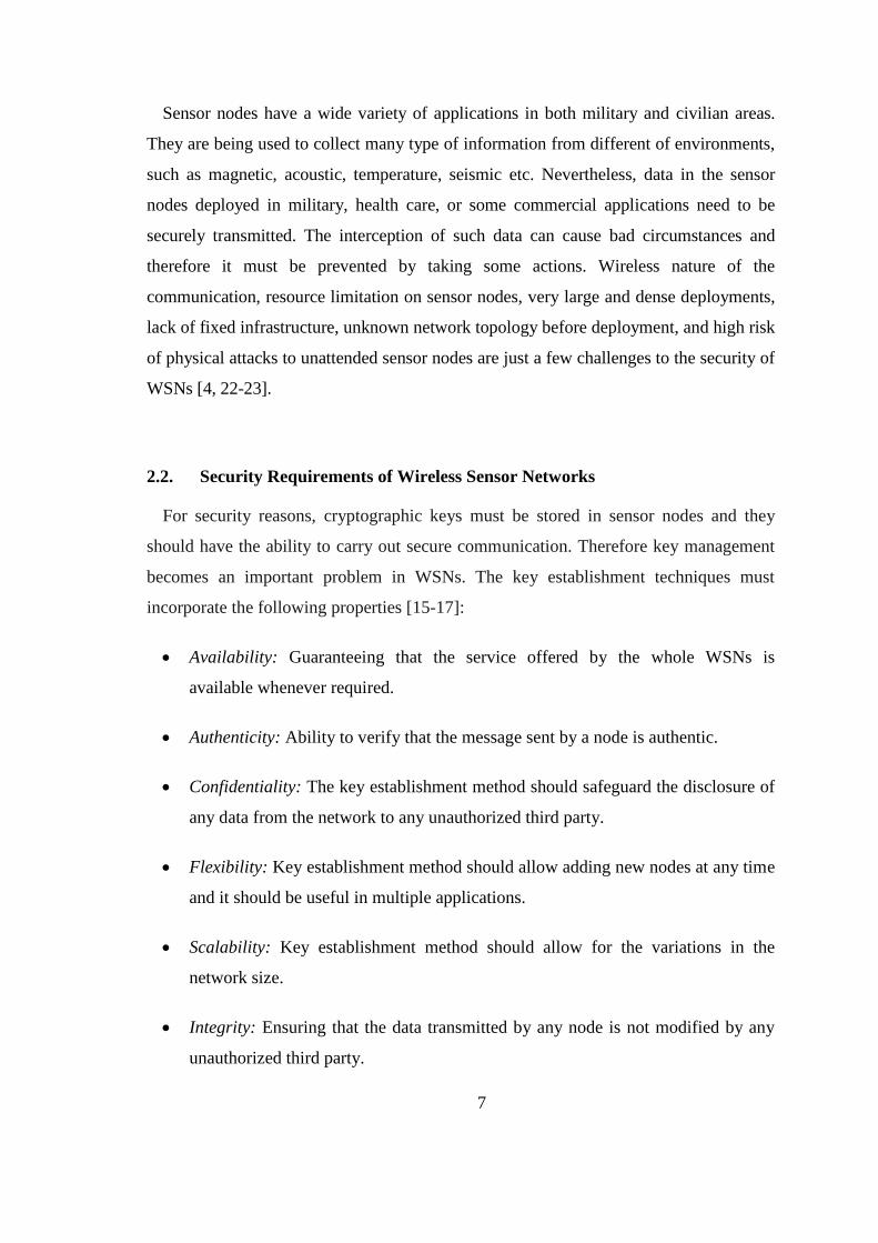


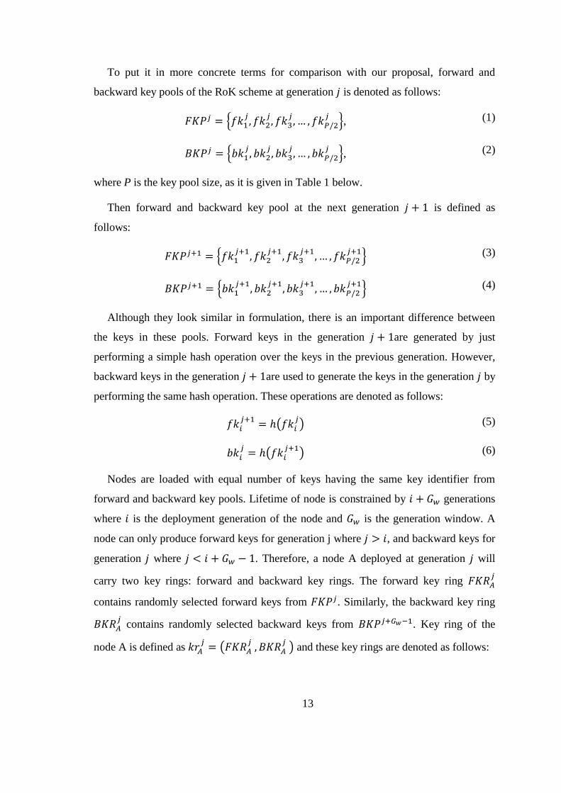


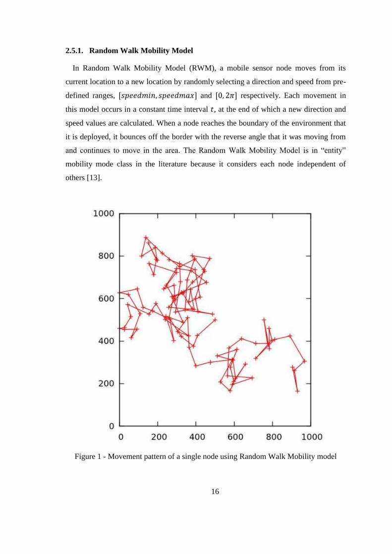
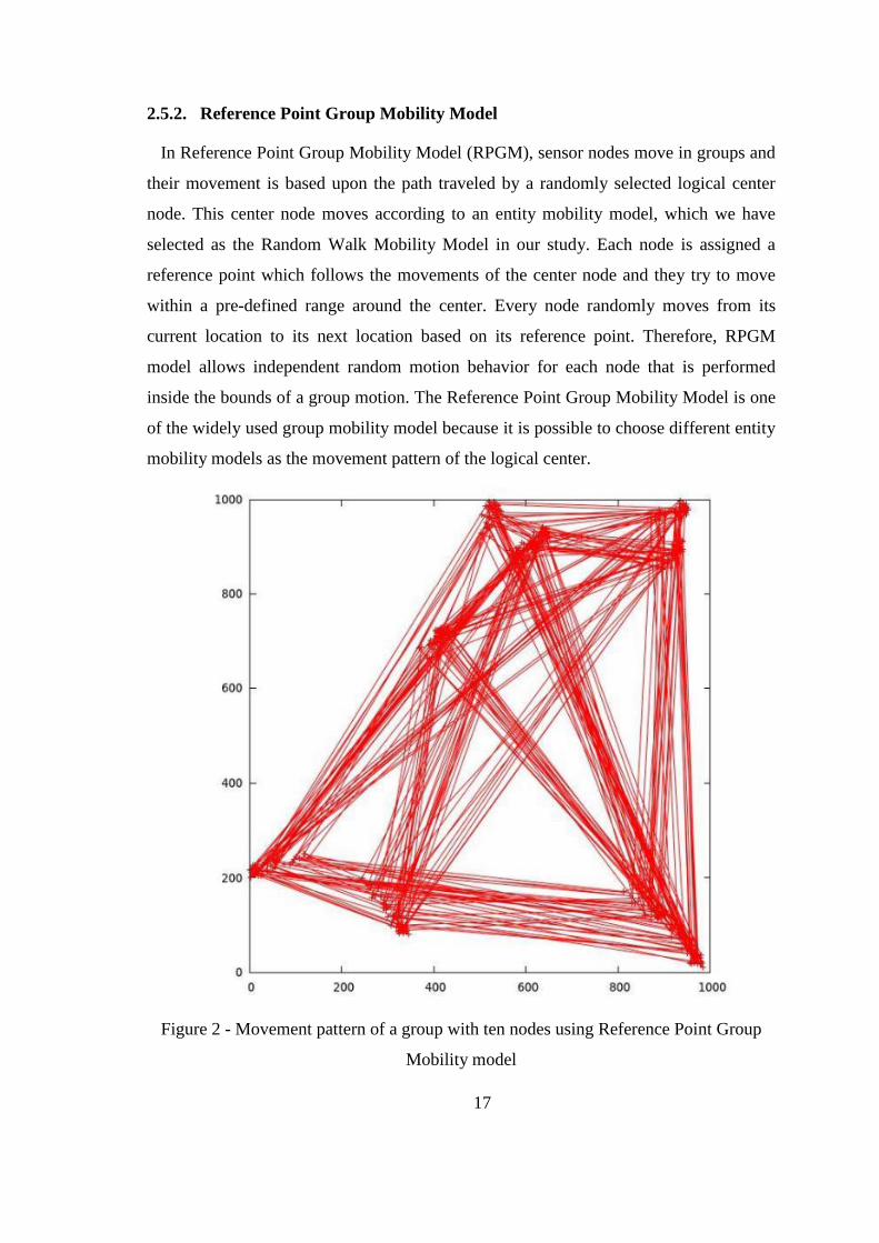
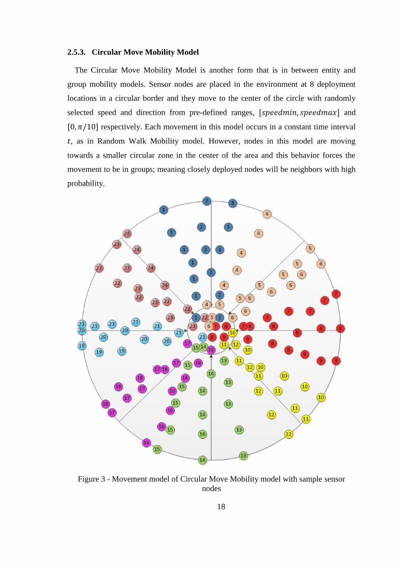
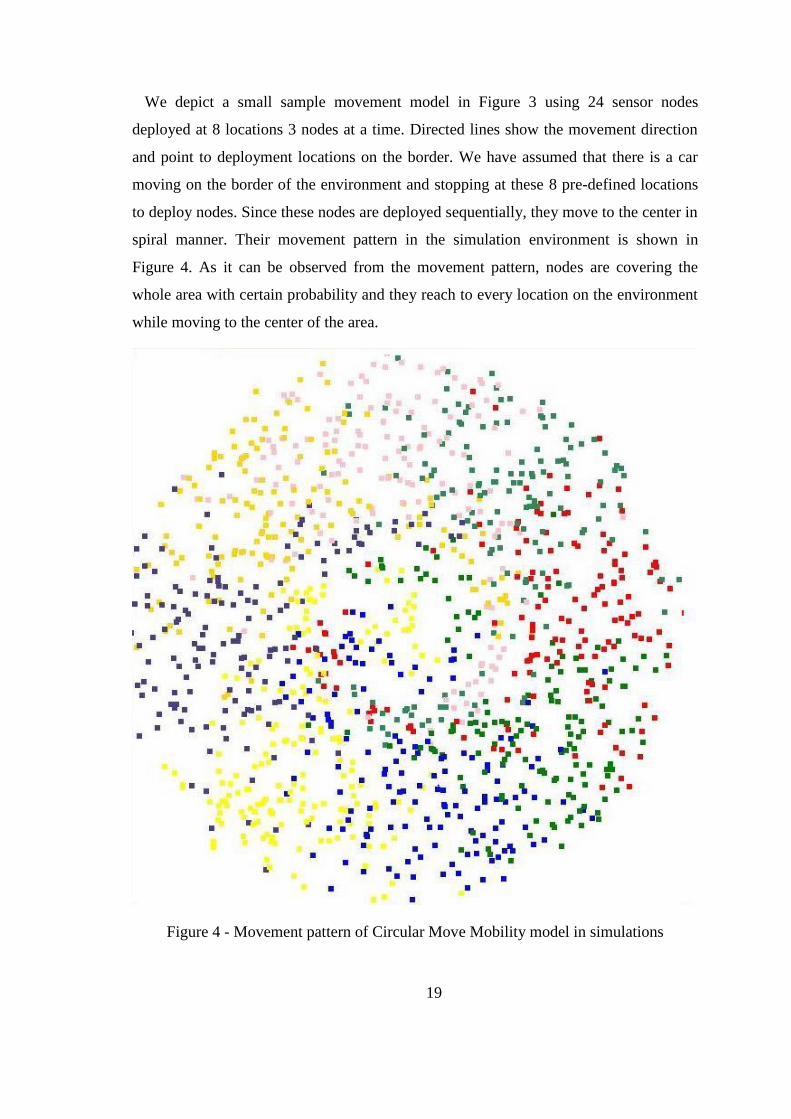


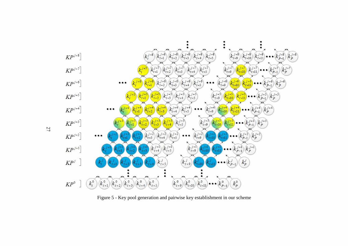


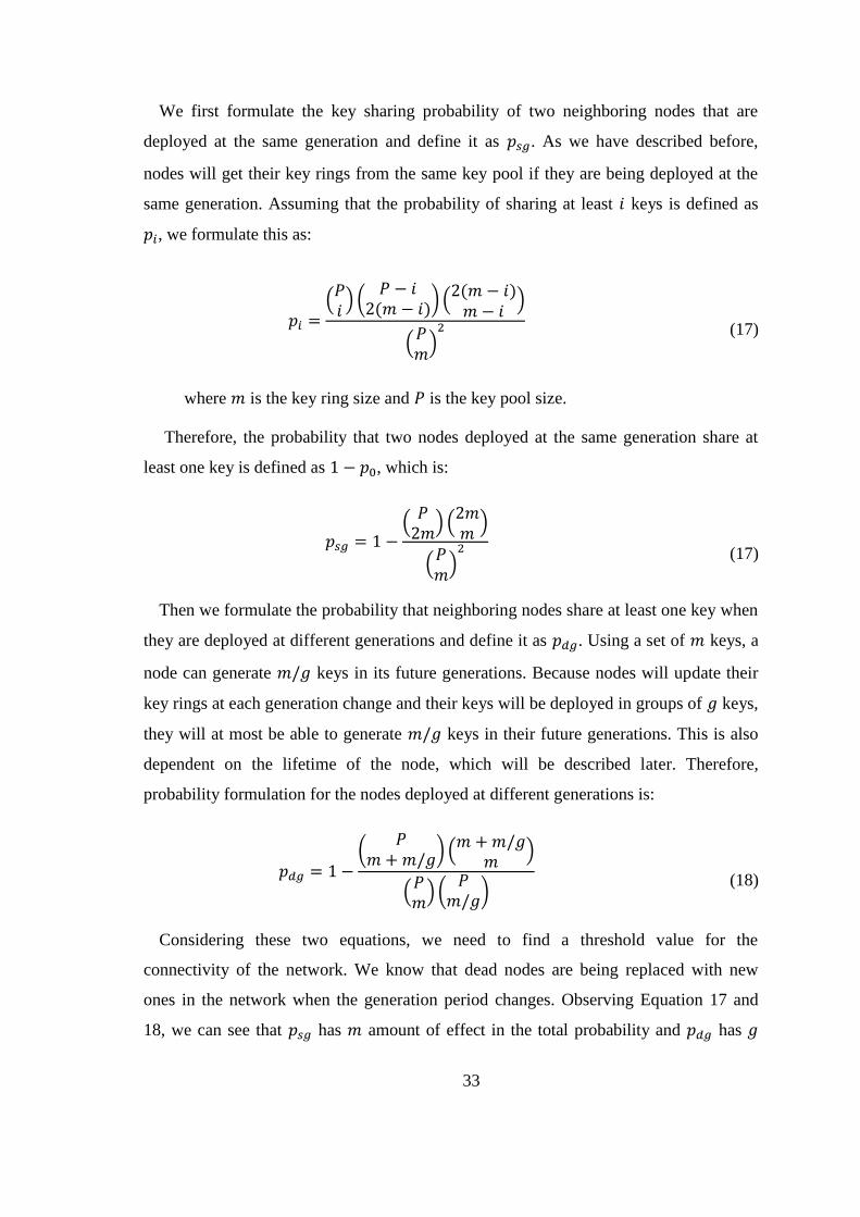


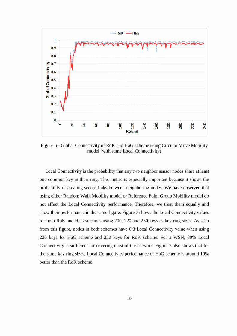
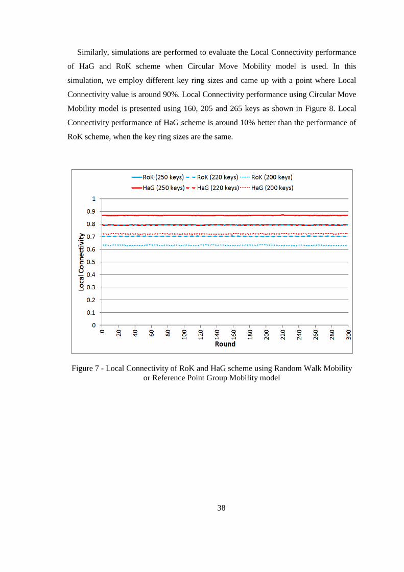

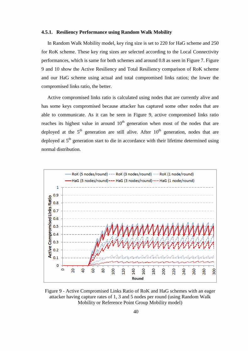

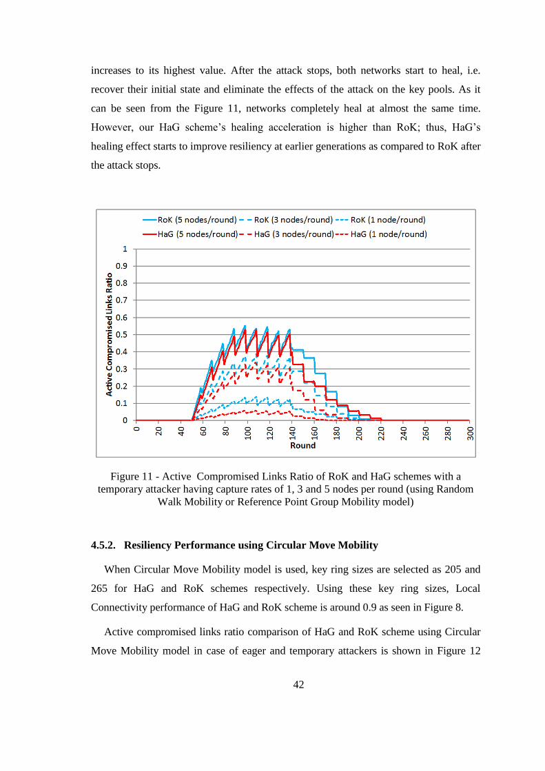
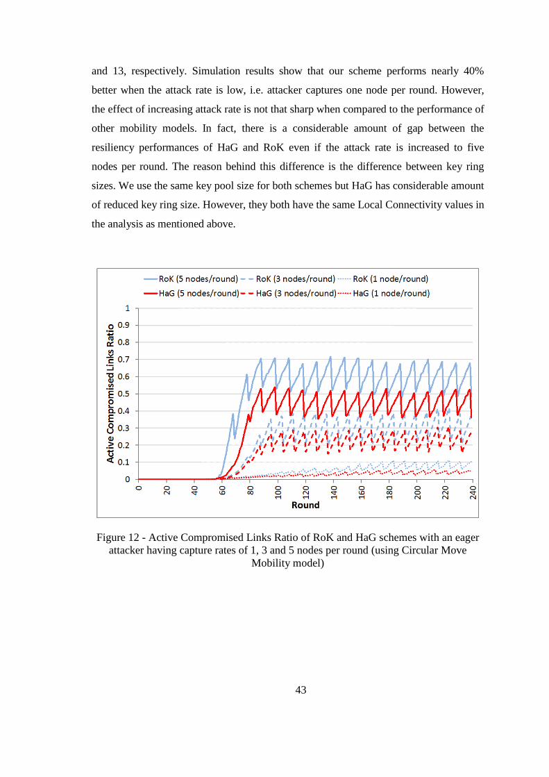
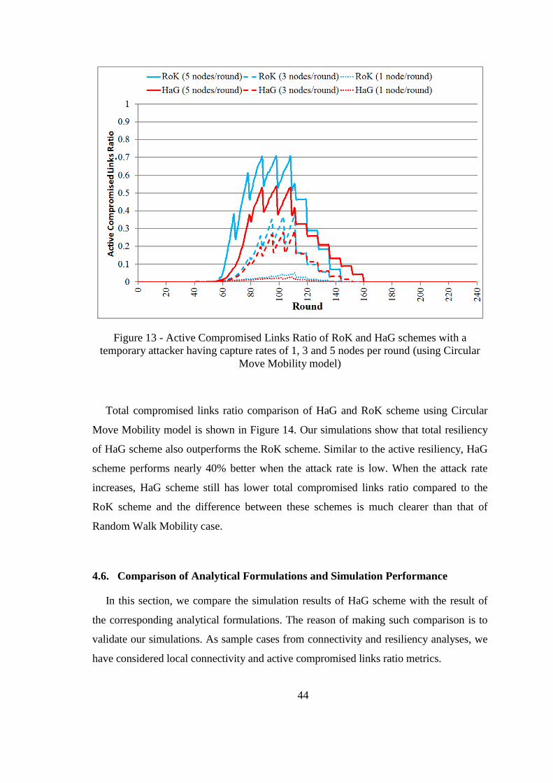

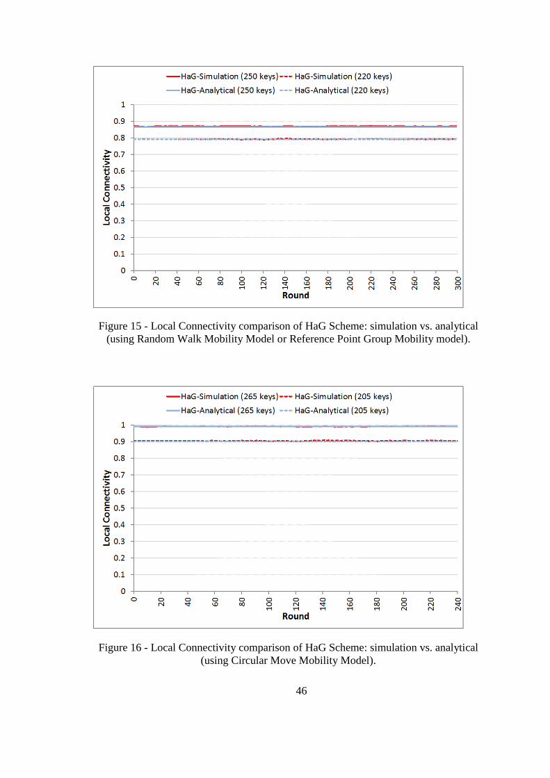

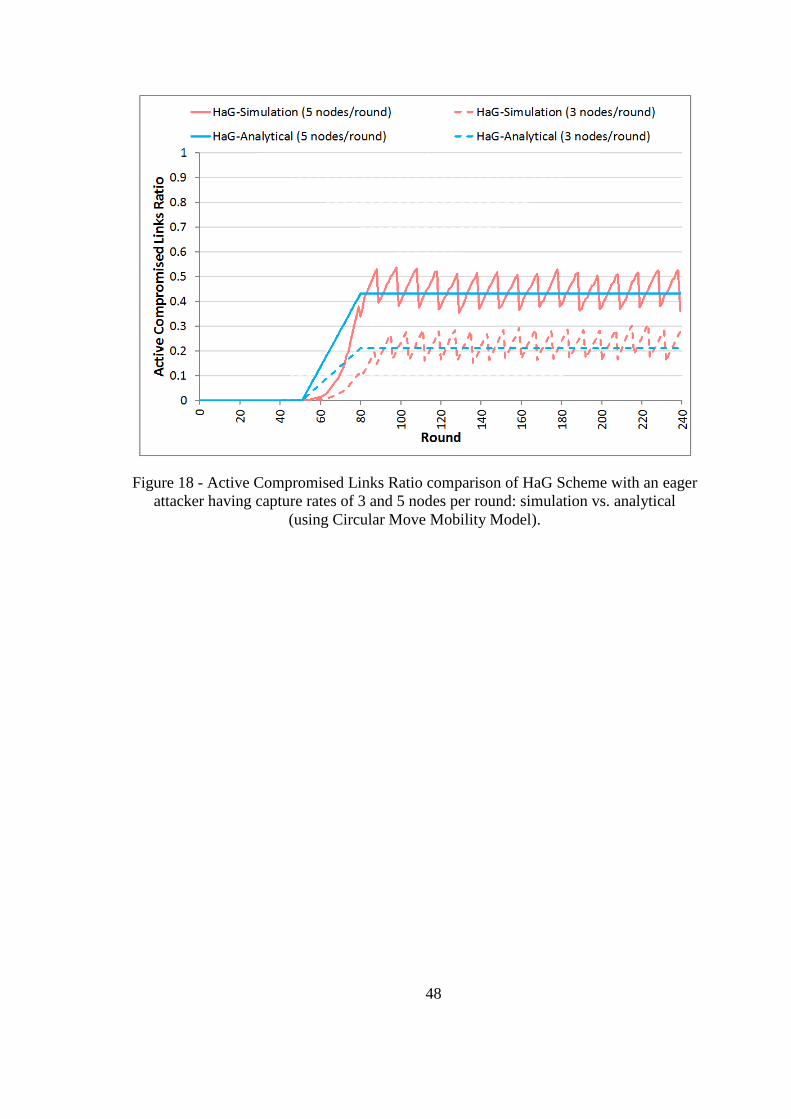


![Evolving Hash Functions using Genetic Algorithmsajiips.com.au/papers/V4.1/V4N1.4 - Evolving Hash Functions using... · hash function called "PKP Hash" by Peter.K.Pearson [5] that](https://static.documents.pub/doc/80x56/5e3486a76e7276290f0add90/evolving-hash-functions-using-genetic-evolving-hash-functions-using-hash.jpg)


