48
Hazardous Location Products and Applications

Hazardous Location
Products and Applications
Automation
Flexible – Fieldbus-Independent – Decentralized
Programmable Fieldbus Controller (PLC)
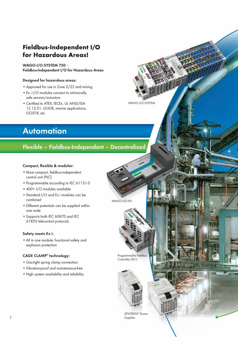
Fieldbus-Independent I/O for Hazardous Areas! WAGO-I/O-SYSTEM 750 −Fieldbus-Independent I/O for Hazardous Areas
Compact, flexible & modular:• Most compact, fieldbus-independent
control unit (PLC)• Programmable according to IEC 61131-3• 400+ I/O modules available• Standard I/O and Ex i modules can be
combined• Different potentials can be supplied within
one node• Supports both IEC 60870 and IEC
61850 telecontrol protocols
Safety meets Ex i: • All in one module: functional safety and
explosion protection
CAGE CLAMP® technology:• Gas-tight spring clamp connection• Vibration-proof and maintenance-free• High system availability and reliability
WAGO-I/O-IPC
EPSITRON® Power Supplies
WAGO-I/O-SYSTEM
Designed for hazardous areas: • Approved for use in Zone 2/22 and mining• Ex i I/O modules connect to intrinsically
safe sensors/actuators• Certified to ATEX, IECEx, UL ANSI/ISA
12.12.01, UL508, marine applications, GOST-R, etc.
2

Reliable – Fast – Maintenance-Free
Electrical Connection Technology
TOPJOB® S Rail-Mounted Terminal Blocks 0.14–16 mm2 (24–6 AWG)
PCB Terminal Blocks
Ex e Junction Box Connectors
Rail-Mount Terminal Block Systems All through and ground conductor terminal blocks of the TOPJOB® S rail-mount terminal block system, as well as the special Ex high-current terminal blocks are suitable for use in Ex e I/II areas.
They provide the most reliable connection for extreme environmental conditions, such as gas, dust or mines.
The X-COM® S pluggable connector system, which combines DIN-rail terminal blocks and female plugs, is also available for Ex appli-cations. The components of the X-COM®S-SYSTEM are non-sparking (“nA” type of protection) and approved for use in Zone 2 hazardous areas.
Your benefits at a glance: • Industry’s widest range of rail-mount terminal
blocks from 0.14–95 mm2 (24–4/0 AWG)• Suitable for all conductor types• CAGE CLAMP® S push-in termination technol-
ogy – for solid and ferruled conductors• POWER CAGE CLAMP – reliably connects
large-gauge wires without a lot of prepara-tion
• Comprehensive jumper system for virtually any application
• Industry‘s fastest and most cost-effective marking system
• TOPJOB® S: vibration-proof, fast and maintenance-free
Pluggable DIN-Rail Terminal Blocks: X-COM®S-SYSTEM
POWER CAGE CLAMP High-Current DIN-Rail Terminal Blocks from 6 to 95 mm² (10–4/0 AWG)
3

Use in Hazardous Areas
For operation as a “Category 3 device” (in Zone 2 or 22), the WAGO-I/O SYSTEM 750-*** must be installed in an enclosure that meets the requirements for a device according to Directive 94/9/EC and the corresponding standards (see ID marking) EN 60079-0, EN 60079-11, EN 60079-15, EN 61241-0 and EN 61241-1. For operation as a device of Group I, Category M2, the device must be installed in an enclosure that affords adequate protection based on EN 61241-0 and EN 61241-1. A declaration of conformity based on Appendix X of Direc-tive 94/9/EC must confirm the correct installation of the devices cited above in the enclosure or control cabinet.
Zone 20Zone 0
WAGO-I/O-SYSTEM
IEC 61511 EN IEC 62061 EN ISO 13849Fail-safe digital input module for sensors
in Ex Zones 0/20 and 1/21Installation in Ex Zone 2/22Features 4 intrinsically safe inputs with functional safetyRated up to SIL 3, Cat. 4/PL e PROFIsafeModule width: 24 mm
4

TOPJOB® S Rail-Mounted Terminal Blocks
The TOPJOB® S series of DIN-rail terminal blocks is designed for use in Ex e I/II areas and ideal for a wide range of indus-trial and building applications.
Their compact design (from 3.5 mm terminal block width) provides more room for wiring, or smaller control cabinets. The many marking options available also ensure a clear overview and extra safety.
TOPJOB® S through terminal blocks with blue insulated hous-ing are suitable for use in Ex i areas.
All TOPJOB® S through and ground conductor terminal blocks are suitable for use in Ex e II areas.
TOPJOB® S through and ground conductor terminal blocks are all certified for use in haz-ardous areas. When Ex e and Ex i circuits are combined, a space-efficient separator plate can be used to maintain the “safety” gap of 50 mm.
Zone 2Zone 22Zone 21Zone 20
Zone 1Zone 0
Hazardous area Non-hazardous area X-COM®S-SYSTEMBoth X-COM®S-SYSTEM carrier terminal blocks and female plugs (see pictures above) are approved for use in Ex nA and Zone 2 hazardous areas. The female plugs also feature a shorter locking lever, making accidental disconnection even more difficult.
X-COM®S-SYSTEM Female Plugs
X-COM®S-SYSTEM Carrier Terminal Blocks
5

X-COM®S-SYSTEM for Ex Applications: A System Combining Pluggable DIN-Rail Terminal Blocks and Connectors
Flexible and Safe, Even in Hazardous Areas
X-COM®S-SYSTEM is ap-proved for ignition protec-tion type “nA” and Zone 2 hazardous areas. “n” refers to an ignition protection class in Zone 2: This zone covers areas in which a dan-gerous, explosive atmosphere consisting of gases, vapors or dust is unlikely to manifest and will only persist for a short period if it does.
“A” means: non-sparking (function modules without relays/switches)
Commoning
Coding
Marking using marking strips or WMB markers. Remove coding finger using a cutting tool.
Marking
6

X-COM®S-SYSTEM for Ex Applications: A System Combining Pluggable DIN-Rail Terminal Blocks and Connectors
Flexible and Safe, Even in Hazardous Areas
Benefits of using the X-COM®S-SYSTEM with Ex approvalBefore assembly:• Preassembly and testing of all components On site:• Quick replacement of pre-assembled components in systems that are difficult to access • Both mismating and touch-proof protections provide reliable assembly even by external service
providers • Fast and reliable maintenance work helps minimizing downtimes Time- and cost-saving system wiring
Coding
Ex marking
“Ex” sign and extended item number “…/0999-0953” are printed on the side of both carrier terminal blocks and female plugs with Ex approval.
Shorter locking lever (factory-mounted) makes accidental disconnection even more difficult.
Strain relief
Insert coding pin into the corresponding slot and twist it off.
(Same handling for X-COM®S-SYSTEM-MINI (picture shows 2020 Series) and X-COM®S-SYSTEM, 2022 Series) 7

Offshore
WAGO-I/O-SYSTEM
Tank Measurement and Alarm Management In addition to standard ship approvals, special ships must adhere to a wide range of different specifications and also place special demands on propulsion control and alarm monitoring.
The widest array of signals (Ex, Non-Ex), for example, must be integrated into the automation system. An easy task for the WAGO-I/O-SYSTEM.
• Large selection of I/O modules• Ex and non-Ex signals in one single node• Safe connections for all products• Compact products
TOPJOB® S Rail-Mounted Terminal Blocks
8
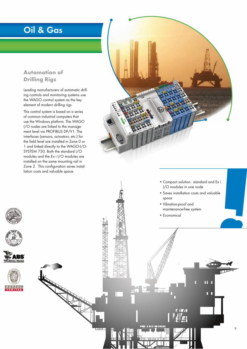
Automation of Drilling Rigs Leading manufacturers of automatic drill-ing controls and monitoring systems use the WAGO control system as the key element of modern drilling rigs.
This control system is based on a series of common industrial computers that use the Windows platform. The WAGO I/O nodes are linked to the manage-ment level via PROFIBUS DP/V1. The interfaces (sensors, actuators, etc.) for the field level are installed in Zone 0 or 1 and linked directly to the WAGO-I/O-SYSTEM 750. Both the standard I/O modules and the Ex i I/O modules are installed on the same mounting rail in Zone 2. This configuration saves instal-lation costs and valuable space.
Oil & Gas
• Compact solution - standard and Ex i I/O modules in one node
• Saves installation costs and valuable space
• Vibration-proof and maintenance-free system
• Economical
9

Petrochemical
Processing
Testing and Calibration of Gas Detection Sensors WAGO-I/O-SYSTEM 750 is the link between the field level and the testing/calibration terminal. For periodic testing of gas detection systems based on Information Sheet T 023 (BGI 518). WAGO products used:• Fieldbus Controller
ETHERNET TCP/IP, 750-880• Ex-i and Non-Ex 750 Series I/O Modules
4 ... 10 mA
4 ... 10 mA 4 ... 10 mA
4 ... 10 mA
ETHERNET
Medium converter
Gas sensors
Gas detection center
ETHERNET gateway
Non-hazard-ous area
Zone 1
Zero gas
Test gas
Test gas valves
Flow controllerEx-d box
• Very compact (12 mm module width) and simple solution
• Ex i and standard modules in a single node
• Web visualization• Support and service for application devel-
opment
WAGO-I/O-SYSTEM ETH
ERN
ET v
ia o
ptic
fiber
line
PC terminal
10

Power Supply
Telecontrol Technology for Gas Control Sta-tions Flow rates must be switched to the cen-tralized control system of a gas supplier and, therefore, be transmitted according to the IEC 60 870-5-104 communication standard. In addition, the pumps must be switched using an on-site control system. The sensors are located in Ex Zone 1 and must be supplied via products suit-able for use in Ex i zones.WAGO products used:• PERSPECTO® Panel• Telecontroller, 750-872• ETHERNET Switch, 852-11
• WAGO-I/O SYSTEM performs automation and telecontrol tasks
• It allows for direct connection of Ex signals• It can be programmed according to IEC
61131-3• The controller can be programmed as a
software controller
ETH
ERN
ET
Communication acc. to IEC 60870-5-104
11

Water Resource
Management
Filtering Plant In wastewater treatment facilities, the challenges placed on interconnect and automation technology not only come from the harsh atmosphere, but also from its use in hazardous areas.
Dangerous and explosive mixtures, which represent a great hazard potential, can be created on unauthorized or accidental dumping of flammable to highly flam-mable fluids, such as gasoline, into the sewage system. The same applies to the liberation (out-gassing) of highly flam-mable methane and digester gases in screening buildings and digestion towers at the sewage treatment facility. Even dur-ing drying of sewage sludge, dangerous concentrations of dust can collect on
• One node combines both “standard” and Ex i intrinsically safe modules
• Saves installation costs and valuable space
• Vibration-proof and maintenance-free system
account of the structure and density of the sewage sludge. The flexibility of the rail-mounted terminal block system and automation solutions is therefore of utmost importance both for the planners and for the operators of such facilities. With its rail-mounted terminal block system and WAGO-I/O-SYSTEM 750 automation solutions, WAGO offers the concept consistency for implementing both standard applications as well as solutions in hazardous areas.
12

Mechanical
Engineering
WAGO products used:• WAGO-I/O-SYSTEM• 870 Series Rail-Mounted Terminal Blocks
with CAGE CLAMP® connection • Connection via X-COM®-SYSTEM
Packing and Filling WAGO-I/O-SYSTEM: Flexible meets flexible
When a machine had to be developed for filling deodorant sticks and for a quick change to other product formats, the WAGO-I/O-SYSTEM was called upon. In addition to its high degree of flexibility, fieldbus independence was a major highlight. The outcome of this development is a system that can accommodate nearly all of the standard seals on the market and is therefore used for filling of different products.
When filling deodorant sticks, for ex-ample, explosive gases are set free due to the volatile alcohol used. This also re-quires the use of intrinsically safe products for hazardous areas in the control system.
• Quick format change of the system to other products for filling
• Use of ATEX-certified modules directly in Zones 1 and 0
• Fieldbus-independent WAGO-I/O-SYSTEM
13

Illustration Description Series Technical Data Certificate/Certifi-cate Number
Degree of Protection
TOPJOB® S Rail-Mounted Terminal Blocks
TOPJOB® S Through/Ground Conductor Terminal Blocks
2000
0.14–1.5 mm2 (24–16 AWG), 550 V, 12!–13 A
0.14–1.5 mm2 (24–16 AWG)
IECEx PTB 11.0093U
PTB 11 ATEX 1041 UEx e I/II
TOPJOB® S Through/Ground Conductor Terminal Blocks
2001
0.5 – 2.5 mm2, 550 V, 17 A
0.5–2.5 mm2 (20–14 AWG)
IECEx PTB 05.0034U
PTB 05 ATEX 094 UEx e I/II
TOPJOB® S Through/Ground Conductor Terminal Blocks
2002
0.25–4 mm2 (22–12 AWG), 440–550 V, 20!–22 A
0.25–4 mm2 (22–12 AWG)
IECEx PTB 03.0004U
PTB 03 ATEX1162UEx e I/II
TOPJOB® S Through/Ground Conductor Terminal Blocks
2004
0.5–6 mm2 (20–10 AWG), 550 V, 30 A
0.5–6 mm2 (20–10 AWG)
IECEx PTB 05.0033U
PTB 05 ATEX 1095 UEx e I/II
TOPJOB® S Through/Ground Conductor Terminal Blocks
2006
0.5–10 mm2 (20–8 AWG), 550 V, 33!–38 A
0.5 – 10 mm2 (20–8 AWG)
IECEx PTB 05.0014U
PTB 05 ATEX 1030 UEx e I/II
TOPJOB® S Through/Ground Conductor Terminal Blocks
2010
0.5–16 mm2 (20–6 AWG), 550 V, 50!–51 A
0.5–16 mm2 (20–6 AWG)
IECEx PTB 06.0003U
PTB 05 ATEX 1070 UEx e I/II
TOPJOB® S Through/Ground Conductor Terminal Blocks
2016
0.5–25 mm2/20–4 AWG (25 mm2/4 AWG “s” only), 550 V, 65!–70 A
0.5–25 mm2 (20–4 AWG)
IECEx PTB 05.0015U
PTB 05 ATEX1031 UEx e I/II
TOPJOB® S Double-Deck Terminal Blocks
2-Conductor Through and Ground Conductor Terminal Block
2002" 0.25–4 mm2 (22–12 AWG), 440 V, 18!–20 A
IECEx PTB 03.0004U
PTB 03 ATEX 1162 UEx e I/II
TOPJOB® S Double-Deck Terminal Blocks
4-Conductor Through and Ground Conductor Terminal Block
2002" 0.25–4 mm² (22–12 AWG), 550 V, 16!–21 A
ECEx PTB 03.0004U
PTB 03 ATEX 1162 UEx e I/II
TOPJOB® S Triple-Deck Terminal Blocks
2-Conductor Through and Ground Conductor Terminal Block
2002" 0.25–4 mm2 (22–12 AWG), 440 V, 17!–19 A
IECEx PTB 03.0004U
PTB 03 ATEX 1162 UEx e I/II
"May not be used as a shield terminal block in hazardous areas!When used with a jumper
14

Volume 1 – Rail-Mounted Terminal Block Systems • Rail-Mounted Terminal Blocks• Modular Pluggable Connectors
X-COM®-SYSTEM and X-COM®S-SYSTEM• Patchboard Systems• Terminal Strips• PUSH WIRE® Connectors for Junction Boxes• Lighting Connectors• Shield (Screen) Connecting System
Volume 2 – PCB Terminal Blocks and Connectors • PCB Terminal Blocks• Feedthrough Terminal Blocks• MULTI CONNECTION SYSTEM (MCS)• Pluggable PCB Terminal Blocks• Specialty Connectors
Illustration Description Series Technical Data Certificate/Certifi-cate Number
Degree of Protection
X-COM®S-SYSTEM ‒ Pluggable DIN-Rail Terminal Blocks
X-COM®S-SYSTEM 1-Conductor/1-Pin
Carrier and Ground Conductor Terminal Block
20220.25–4 mm² (22–12 AWG), 690 V, 20 A
0.25–4 mm² (22–12 AWG)
PTB 12 ATEX 1004 U Ex nA
X-COM®S-SYSTEM 2-Conductor/1-Pin
Carrier and Ground Conductor Terminal Block
20220.25–4 mm² (22–12 AWG), 690 V, 20 A
0.25–4 mm² (22–12 AWG)
PTB 12 ATEX 1004 U Ex nA
X-COM®S-SYSTEM 1-Conductor/1-Pin
Double-Deck Terminal Block
Carrier and Ground Conductor Terminal Block
2022
0.25–4 mm² (22–12 AWG), 690 V, 20 A/!19 A
0.25–4 mm² (22–12 AWG)
PTB 12 ATEX 1004 U Ex nA
X-COM®S-SYSTEM 1-Conductor Female Plug
20220.25–4 mm² (22–12 AWG), 690 V, 20 A
0.25–4 mm² (22–12 AWG)
PTB 12 ATEX 1004 U Ex nA
!When used with a jumper
15

Illustration Description Series Technical Data Certificate/Certifi-cate Number
Degree of Protection
Front-Entry, Rail-Mounted Terminal Blocks
2-Conductor Through Terminal Block 279-904 0.08–1.5 mm2 (28–16 AWG), 800 V, 18 A Ex i
3-Conductor Through Terminal Block 279-684 0.08–1.5 mm2 (28–16 AWG), 800 V, 18 A Ex i
4-Conductor Through Terminal Block 279-834 0.08–1.5 mm2 (28–16 AWG), 800 V, 18 A Ex i
2-Conductor Through Terminal Block 280-904 0.08–2.5 mm2 (28–14 AWG), 800 V, 18 A Ex i
3-Conductor Through Terminal Block 280-684 0.08–2.5 mm2 (28–14 AWG), 800 V, 24 A Ex i
3-Conductor Through Terminal Block 280-651 0.08–2.5 mm2 (28–14 AWG), 800 V, 24 A Ex i
4-Conductor Through Terminal Block 280-834 0.08–2.5 mm2 (28–14 AWG), 800 V, 20 A Ex i
4-Conductor Through Terminal Block 280-656 0.08–2.5 mm2 (28–14 AWG), 800 V, 24 A Ex i
2-Conductor Through Terminal Block 880-904/999-940 0.08–4 mm2 (28–12 AWG), 800 V, 25 A Ex i
3-Conductor Through Terminal Block 880-684/999-940 0.08–4 mm2 (28–12 AWG), 800 V, 25 A Ex i
16

Illustration Description Series Technical Data Certificate/Certifi-cate Number
Degree of Protection
4-Conductor Through Terminal Block 880-834/999-940 0.08–4 mm2 (28–12 AWG), 800 V, 20 A Ex i
2-Conductor Through Terminal Block 281-904 0.08–4 mm2 (28–12 AWG), 800 V, 32 A Ex i
3-Conductor Through Terminal Block 281-684 0.08–4 mm2 (28–12 AWG), 800 V, 32 A Ex i
3-Conductor Through Terminal Block 281-651 0.08–4 mm2 (28–12 AWG), 800 V, 32 A Ex i
4-Conductor Through Terminal Block 281-654 0.08–4 mm2 (28–12 AWG), 800 V, 26 A Ex i
2-Conductor Through Terminal Block 282-904 0.2–6 mm2 (24–10 AWG), 800 V, 41 A Ex i
3-Conductor Through Terminal Block 282-684 0.2–6 mm2 (24–10 AWG), 800 V, 41 A Ex i
Double-Deck Terminal Blocks:
Through/through connection,
4-Conductor Through Terminal Block
279-504
279-509
0.08–1.5 mm2 (28–16 AWG), 500 V, 18 A Ex i
Double-Deck Terminal Blocks:
Through/through connection,
280-529 0.08–2.5 mm2 (28–14 AWG), 500 V, 20 A Ex i
Volume 1 – Rail-Mounted Terminal Block Systems • Rail-Mounted Terminal Blocks• Modular Pluggable Connectors
X-COM®-SYSTEM and X-COM®S-SYSTEM• Patchboard Systems• Terminal Strips• PUSH WIRE® Connectors for Junction Boxes• Lighting Connectors• Shield (Screen) Connecting System
Volume 2 – PCB Terminal Blocks and Connectors • PCB Terminal Blocks• Feedthrough Terminal Blocks• MULTI CONNECTION SYSTEM (MCS)• Pluggable PCB Terminal Blocks• Specialty Connectors
17

Illustration Description Series Technical Data Certificate/Certifi-cate Number
Degree of Protection
4-Conductor Chassis-Mount Terminal Strips
2-pole, M3 screw
2-pole, tapping screw
2-pole, with snap-in mounting foot
862-1552/999-950
862-1562/999-950
862-1532/999-950
0.5 – 4 mm2 (20–12 AWG), 440 V, 28 A
0.5 – 4 mm2 (20–12 AWG), 440 V, 28 A
0.5 – 4 mm2 (20–12 AWG), 440 V, 28 A
IECEx PTB 05.0003 U
PTB 03 ATEX 1189 UEx e I/II
2-pole, M3 screw
2-pole, tapping screw
2-pole, with snap-in mounting foot
862-1652/999-950
862-1662/999-950
862-1632/999-950
0.5 – 4 mm2 (20–12 AWG), 440 V, 28 A
0.5 – 4 mm2 (20–12 AWG), 440 V, 28 A
0.5 – 4 mm2 (20–12 AWG), 440 V, 28 A
IECEx PTB 05.0003 U
PTB 03 ATEX 1189 UEx e I/II
3-pole, M3 screw
3-pole, tapping screw
3-pole, with snap-in mounting foot
862-1503/999-950
862-1533/999-950
862-1593/999-950
0.5 – 4 mm2 (20–12 AWG), 440 V, 28 A
0.5 – 4 mm2 (20–12 AWG), 440 V, 28 A
0.5 – 4 mm2 (20–12 AWG), 440 V, 28 A
IECEx PTB 05.0003 U
PTB 03 ATEX 1189 UEx e I/II
3-pole, M3 screw
3-pole, tapping screw
3-pole, with snap-in mounting foot
862-1603/999-950
862-1633/999-950
862-1693/999-950
0.5 – 4 mm2 (20–12 AWG), 440 V, 28 A
0.5 – 4 mm2 (20–12 AWG), 440 V, 28 A
0.5 – 4 mm2 (20–12 AWG), 440 V, 28 A
IECEx PTB 05.0003 U
PTB 03 ATEX 1189 UEx e I/II
4-pole, M3 screw
4-pole, tapping screw
4-pole, with snap-in mounting foot
862-1504/999-950
862-1534/999-950
862-1594/999-950
0.5 – 4 mm2 (20–12 AWG), 440 V, 28 A
0.5 – 4 mm2 (20–12 AWG), 440 V, 28 A
0.5 – 4 mm2 (20–12 AWG), 440 V, 28 A
IECEx PTB 05.0003 U
PTB 03 ATEX 1189 UEx e I/II
4-pole, M3 screw
4-pole, tapping screw
4-pole, with snap-in mounting foot
862-1604/999-950
862-1634/999-950
862-1694/999-950
0.5 – 4 mm2 (20–12 AWG), 440 V, 28 A
0.5 – 4 mm2 (20–12 AWG), 440 V, 28 A
0.5 – 4 mm2 (20–12 AWG), 440 V, 28 A
IECEx PTB 05.0003 U
PTB 03 ATEX 1189 UEx e I/II
5-pole, M3 screw
5-pole, tapping screw
5-pole, with snap-in mounting foot
862-1505/999-950
862-1535/999-950
862-1595/999-950
0.5 – 4 mm2 (20–12 AWG), 440 V, 28 A
0.5 – 4 mm2 (20–12 AWG), 440 V, 28 A
0.5 – 4 mm2 (20–12 AWG), 440 V, 28 A
IECEx PTB 05.0003 U
PTB 03 ATEX 1189 UEx e I/II
5-pole, M3 screw
5-pole, tapping screw
5-pole, with snap-in mounting foot
862-1605/999-950
862-1635/999-950
862-1695/999-950
0.5 – 4 mm2 (20–12 AWG), 440 V, 28 A
0.5 – 4 mm2 (20–12 AWG), 440 V, 28 A
0.5 – 4 mm2 (20–12 AWG), 440 V, 28 A
IECEx PTB 05.0003 U
PTB 03 ATEX 1189 UEx e I/II
18

Illustration Description Series Technical Data Certificate/Certifi-cate Number
Degree of Protection
Front-Entry, Rail-Mounted Terminal Blocks
2-Conductor Through Terminal Block
2-Conductor Ground Terminal Block
279-992
279-907/999-950
0.08–1.5 mm2 (28–16 AWG), 500 V, 15 A
0.2 – 1.5 mm2 (24–16 AWG)
PTB 00 ATEX 3113 U Ex e I/II
3-Conductor Through Terminal Block
3-Conductor Ground Terminal Block
279-993
279-687/999-950
0.08–1.5 mm2 (28–16 AWG), 500 V, 15 A
0.2 – 1.5 mm2 (24–16 AWG)
PTB 00 ATEX 3113 U Ex e I/II
4-Conductor Through Terminal Block
2-Conductor Ground Terminal Block
279-994
279-837/999-950
0.08–1.5 mm2 (28–16 AWG), 500 V, 15 A
0.2 – 1.5 mm2 (24–16 AWG)
PTB 00 ATEX 3113 U Ex e I/II
2-Conductor Through Terminal Block
2-Conductor Ground Terminal Block
280-992
280-907/999-950
0.2–2.5 mm2 (24–14 AWG), 550 V, 23 A
0.2–2.5 mm2 (24–14 AWG)
PTB 00 ATEX 3109 U Ex e I/II
3-Conductor Through Terminal Block
3-Conductor Ground Terminal Block
280-993
280-687/999-950
0.2–2.5 mm2 (24–14 AWG), 550 V, 22 A
0.2–2.5 mm2 (24–14 AWG)
PTB 00 ATEX 3109 U Ex e I/II
3-Conductor Through Terminal Block
3-Conductor Ground Terminal Block
280-998
280-637/999-950
0.2–2.5 mm2 (24–14 AWG), 550 V, 23 A
0.2–2.5 mm2 (24–14 AWG)
PTB 00 ATEX 3109 U Ex e I/II
4-Conductor Through Terminal Block
2-Conductor Ground Terminal Block
280-994
280-837/999-950
0.2–2.5 mm2 (24–14 AWG), 550 V, 20 A
0.2–2.5 mm2 (24–14 AWG)
PTB 00 ATEX 3109 U Ex e I/II
4-Conductor Through Terminal Block 280-996 0.2–2.5 mm2 (24–14 AWG), 550 V, 23 A PTB 00 ATEX 3109 U Ex e I/II
Volume 1 – Rail-Mounted Terminal Block Systems • Rail-Mounted Terminal Blocks• Modular Pluggable Connectors
X-COM®-SYSTEM and X-COM®S-SYSTEM• Patchboard Systems• Terminal Strips• PUSH WIRE® Connectors for Junction Boxes• Lighting Connectors• Shield (Screen) Connecting System
Volume 2 – PCB Terminal Blocks and Connectors • PCB Terminal Blocks• Feedthrough Terminal Blocks• MULTI CONNECTION SYSTEM (MCS)• Pluggable PCB Terminal Blocks• Specialty Connectors
19

Illustration Description Series Technical Data Certificate/Certifi-cate Number
Degree of Protection
Front-Entry, Rail-Mounted Terminal Blocks
2-Conductor Through Terminal Block
2-Conductor Ground Terminal Block
281-992
281-907/999-950
0.2–4 mm2 (24–12 AWG), 550 V, 30 A
0.2–4 mm2 (24–12 AWG)
PTB 00 ATEX 3110 U Ex e I/II
3-Conductor Through Terminal Block
3-Conductor Ground Terminal Block
281-993
281-687/999-950
0.2–4 mm2 (24–12 AWG), 550 V, 30 A
0.2–4 mm2 (24–12 AWG)
PTB 00 ATEX 3110 U Ex e I/II
3-Conductor Through Terminal Block
3-Conductor Ground Terminal Block
281-998
281-637/999-950
0.2–4 mm2 (24–12 AWG), 550 V, 30 A
0.2–4 mm2 (24–12 AWG)
PTB 00 ATEX 3110 U Ex e I/II
4-Conductor Through Terminal Block
2-Conductor Ground Terminal Block
281-994
281-657/999-950
0.2–4 mm2 (24–12 AWG), 550 V, 30 A
0.2–4 mm2 (24–12 AWG)
PTB 00 ATEX 3110 U Ex e I/II
2-Conductor Through Terminal Block
2-Conductor Ground Terminal Block
282-992
282-907/999-950
0.2–6 mm2 (24–10 AWG), 550 V, 39 A
0.2 – 6 mm2 (24–10 AWG)
PTB 98 ATEX 3131 U Ex e I/II
3-Conductor Through Terminal Block
3-Conductor Ground Terminal Block
282-993
282-687/999-950
0.2–6 mm2 (24–10 AWG), 550 V, 39 A
0.2 – 6 mm2 (24–10 AWG)
PTB 98 ATEX 3131 U Ex e I/II
2-Conductor Through Terminal Block
2-Conductor Ground Terminal Block
284-992
284-907/999-950
0.2–10 mm2 (24–8 AWG), 550 V, 53 A
0.2–10 mm2 (24–8 AWG)
PTB 98 ATEX 3133 U Ex e I/II
3-Conductor Through Terminal Block
3-Conductor Ground Terminal Block
284-993
284-687/999-950
0.2–10 mm2 (24–8 AWG), 550 V, 53 A
0.2–10 mm2 (24–8 AWG)
PTB 98 ATEX 3133 U Ex e I/II
20

Illustration Description Series Technical Data Certificate/Certifi-cate Number
Degree of Protection
Front-Entry, Rail-Mounted Terminal Blocks
2-Conductor Through Terminal Block
2-Conductor Ground Terminal Block
283-992
283-907/999-950
0.2–16 mm2 (24–6 AWG), 550 V, 68 A
0.2–16 mm2 (24–6 AWG)
PTB 98 ATEX 3132 U Ex e I/II
3-Conductor Through Terminal Block
3-Conductor Ground Terminal Block
283-998
283-677/999-950
0.2–16 mm2 (24–6 AWG), 550 V, 68 A
0.2–16 mm2 (24–6 AWG)
PTB 98 ATEX 3132 U Ex e I/II
2-Conductor Through Terminal Block 285-992 6 – 35 mm2 (10–2 AWG), 880 V, 109 A PTB 98 ATEX 3134 U Ex e I/II
Front-Entry, Rail-Mounted Terminal Blocks
Double-Deck Terminal Blocks:
Through/through connection with horizontal jumper position
280-530 0.08–2.5 mm2 (28–14 AWG), 500 V, 20 A Ex i
Double-Deck Terminal Blocks:
Through/through connection,
281-629 0.08–4 mm2 (28–12 AWG), 500 V, 26 A Ex i
Double-Deck Terminal Blocks:
Through/through connection with horizontal jumper position
281-630 0.08–4 mm2 (28–12 AWG), 500 V, 26 A Ex i
Volume 1 – Rail-Mounted Terminal Block Systems • Rail-Mounted Terminal Blocks• Modular Pluggable Connectors
X-COM®-SYSTEM and X-COM®S-SYSTEM• Patchboard Systems• Terminal Strips• PUSH WIRE® Connectors for Junction Boxes• Lighting Connectors• Shield (Screen) Connecting System
Volume 2 – PCB Terminal Blocks and Connectors • PCB Terminal Blocks• Feedthrough Terminal Blocks• MULTI CONNECTION SYSTEM (MCS)• Pluggable PCB Terminal Blocks• Specialty Connectors
21

Illustration Description Series Technical Data Certificate/Certifi-cate Number
Degree of Protection
Front-Entry, Rail-Mounted Terminal Blocks
2-Conductor Disconnect and Test Terminal Blocks 280-876 0.08–2.5 mm2 (28–14 AWG), 400 V, 16 A Ex i
4-Conductor Disconnect/ Test Terminal Blocks 280-885 0.08–2.5 mm2 (28–14 AWG), 400 V, 16 A Ex i
Compact Rail-Mounted Terminal Blocks
2-Conductor Through Terminal Blocks 870-904 0.08–2.5 mm2 (28–14 AWG), 500 V, 24 A Ex i
2-Conductor Through Terminal Blocks
DIN 15 carrier rail870-914 0.08–2.5 mm2 (28–14 AWG), 500 V, 24 A Ex i
3-Conductor Through Terminal Blocks 870-684 0.08–2.5 mm2 (28–14 AWG), 500 V, 24 A Ex i
2-Conductor Through Terminal Blocks
2-Conductor Ground Terminal Block
870-909
870-907/999-950
0.2–4 mm2 (24–12 AWG), 440 V, 22 A
0.2–4 mm2 (24–12 AWG)
IECEx PTB 04.0018U
PTB 03 ATEX 1188 U
Ex e I/II
2-Conductor Through Terminal Blocks
DIN 15 carrier rail870-919 0.2–4 mm2 (24–12 AWG), 440 V, 22 A
IECEx PTB 04.0018U
PTB 03 ATEX 1188 U
Ex e I/II
22

Illustration Description Series Technical Data Certificate/Certifi-cate Number
Degree of Protection
TOPJOB® Classic Rail-Mounted Terminal Blocks, 35° Front-Entry
TOPJOB® Classic
2-Conductor Through Terminal Block
780-604 0.08 – 2.5 mm2 (28–14 AWG), 1000 V, 16 A Ex i
TOPJOB® Classic
3-Conductor Through Terminal Block
780-651 0.08 – 2.5 mm2 (28–14 AWG), 1000 V, 16 A Ex i
TOPJOB® Classic
2-Conductor Through Terminal Block
781-604 0.08 – 4 mm2 (28 -12 AWG), 1000 V, 32 A Ex i
TOPJOB® Classic
3-Conductor Through Terminal Block
781-651 0.08 – 4 mm2 (28 -12 AWG), 1000 V, 32 A Ex i
TOPJOB® Classic
2-Conductor Through Terminal Block
782-604 0.2 – 6 mm2 (24–10 AWG), 1000 V, 41 A Ex i
TOPJOB® Classic
2-Conductor Through Terminal Block
784-604 0.2 –10 mm2 (24 -8 AWG), 1000 V, 57 A Ex i
TOPJOB® Classic
2-Conductor Through Terminal Block
783-604 0.2–16 mm2 (24–6 AWG), 1000 V, 76 A Ex i
TOPJOB® Classic
2-Conductor Through Terminal Block
785-604 6 – 35 mm2 (10–2 AWG), 1000 V, 125 A Ex i
Volume 1 – Rail-Mounted Terminal Block Systems • Rail-Mounted Terminal Blocks• Modular Pluggable Connectors
X-COM®-SYSTEM and X-COM®S-SYSTEM• Patchboard Systems• Terminal Strips• PUSH WIRE® Connectors for Junction Boxes• Lighting Connectors• Shield (Screen) Connecting System
Volume 2 – PCB Terminal Blocks and Connectors • PCB Terminal Blocks• Feedthrough Terminal Blocks• MULTI CONNECTION SYSTEM (MCS)• Pluggable PCB Terminal Blocks• Specialty Connectors
23

Illustration Description Series Technical Data Certificate/Certifi-cate Number
Degree of Protection
TOPJOB® Classic Rail-Mounted Terminal Blocks, 35° Front-Entry
TOPJOB® Classic
2-Conductor Through Terminal Block
2-Conductor Ground Terminal Block
780-992
780-607/999-950
0.2–2.5 mm2 (24–14 AWG), 750 V, 23 A
0.2–2.5 mm2 (24–14 AWG)
PTB 00 ATEX 3128 U Ex e I/II
TOPJOB® Classic
3-Conductor Through Terminal Block
3-Conductor Ground Terminal Block
780-993
780-637/999-950
0.2–2.5 mm2 (24–14 AWG), 750 V, 23 A
0.2–2.5 mm2 (24–14 AWG)
PTB 00 ATEX 3128 U Ex e I/II
TOPJOB® Classic
2-Conductor Through Terminal Block
2-Conductor Ground Terminal Block
781-992
781-607/999-950
0.2–4 mm2 (24–12 AWG), 750 V, 30 A
0.2–4 mm2 (24–12 AWG)
PTB 00 ATEX 3129 U Ex e I/II
TOPJOB® Classic
3-Conductor Through Terminal Block
3-Conductor Ground Terminal Block
781-993
781-637/999-950
0.2–4 mm2 (24–12 AWG), 750 V, 27 A
0.2–4 mm2 (24–12 AWG)
PTB 00 ATEX 3129 U Ex e I/II
TOPJOB® Classic
2-Conductor Through Terminal Block
2-Conductor Ground Terminal Block
782-992
782-607/999-950
0.2–6 mm2 (24–10 AWG), 750 V, 39 A
0.2 – 6 mm2 (24–10 AWG)
PTB 00 ATEX 3130 U Ex e I/II
TOPJOB® Classic
2-Conductor Through Terminal Block
2-Conductor Ground Terminal Block
784-992
784-607/999-950
0.2–10 mm2 (24–8 AWG), 690 V, 53 A
0.2–10 mm2 (24–8 AWG)
PTB 00 ATEX 2132 U Ex e I/II
TOPJOB® Classic
2-Conductor Through Terminal Block
2-Conductor Ground Terminal Block
783-992
783-607/999-950
0.5–16 mm2 (20–6 AWG), 750 V, 68 A
0.5–16 mm2 (20–6 AWG)
PTB 00 ATEX 3131 U Ex e I/II
24

Illustration Description Series Technical Data Certificate/Certifi-cate Number
Degree of Protection
Modular Terminal Blocks
2-Conductor Center Terminal Block
2-Conductor End Terminal Block with Fixing Flange
264-324
264-304
0.08–2.5 mm2 (28–14 AWG), 800 V, 24 A Ex i
4-Conductor Center Terminal Block
4-Conductor End Terminal Block with Fixing Flange
264-354
264-334
0.08–2.5 mm2 (28–14 AWG), 800 V, 24 A Ex i
2-Conductor Terminal Block with Snap-In Mounting Foot 264-314 0.08–2.5 mm2 (28–14 AWG), 800 V, 24 A Ex i
4-Conductor Terminal Block with Snap-In Mounting Foot 264-344 0.08–2.5 mm2 (28–14 AWG), 800 V, 24 A Ex i
2-Conductor Terminal Block with Fixing Flange
2-Conductor Terminal Block with Snap-In Mounting Foot
2-Conductor End Terminal Block
262-304
262-314
262-324
0.08–4 mm2 (28–12 AWG), 630 V, 24 A
0.08–4 mm2 (28–12 AWG), 630 V, 24 A
0.08–4 mm2 (28–12 AWG), 630 V, 24 A
Ex i
4-Conductor Terminal Block with Fixing Flange
4-Conductor Terminal Block with Snap-In Mounting Foot
4-Conductor End Terminal Block
262-334
262-344
262-354
0.08 – 4 mm2 (28–12 AWG), 630 V, 32 A
0.08 – 4 mm2 (28–12 AWG), 630 V, 32 A
0.08 – 4 mm2 (28–12 AWG), 630 V, 32 A
Ex i
2-Conductor Center Terminal Block
2-Conductor End Terminal Block with Fixing Flange
264-131
264-130
0.2–2.5 mm2 (24–14 AWG), 690 V, 23 A
0.2–2.5 mm2 (24–14 AWG), 690 V, 23 A
IECEx PTB 04.0003U
PTB 98 ATEX 3129 U
Ex e I/II
4-Conductor Center Terminal Block
4-Conductor End Terminal Block with Fixing Flange
264-231
264-230
0.2–2.5 mm2 (24–14 AWG), 690 V, 23 A
0.2–2.5 mm2 (24–14 AWG), 690 V, 23 A
IECEx PTB 04.0003U
PTB 98 ATEX 3129 U
Ex e I/II
2-Conductor Terminal Block with Snap-In Mounting Foot 264-180 0.5–2.5 mm2 (20–14 AWG), 690 V, 23 A
IECEx PTB 04.0003U
PTB 98 ATEX 3129 UEx e I/II
4-Conductor Terminal Block with Snap-In Mounting Foot 264-280 0.5–2.5 mm2 (20–14 AWG), 690 V, 23 A
IECEx PTB 04.0003U
PTB 98 ATEX 3129 UEx e I/II
Volume 1 – Rail-Mounted Terminal Block Systems • Rail-Mounted Terminal Blocks• Modular Pluggable Connectors
X-COM®-SYSTEM and X-COM®S-SYSTEM• Patchboard Systems• Terminal Strips• PUSH WIRE® Connectors for Junction Boxes• Lighting Connectors• Shield (Screen) Connecting System
Volume 2 – PCB Terminal Blocks and Connectors • PCB Terminal Blocks• Feedthrough Terminal Blocks• MULTI CONNECTION SYSTEM (MCS)• Pluggable PCB Terminal Blocks• Specialty Connectors
25

Illustration Description Series Technical Data Certificate/Certifi-cate Number
Degree of Protection
4-Conductor Terminal Strip with Fixing Flange
4-Conductor Terminal Strip with Snap-In Mounting Foot
264-132...142
264-182...192
0.5–2.5 mm2 (20–14 AWG), 690 V, 23 A
0.5–2.5 mm2 (20–14 AWG), 690 V, 23 A
IECEx PTB 04.0003U
PTB 98 ATEX 3129 UEx e I/II
4-Conductor Terminal Strip with Fixing Flange
4-Conductor Terminal Strip with Snap-In Mounting Foot
264-232...242
264-282...292
0.5–2.5 mm2 (20–14 AWG), 690 V, 23 A
0.5–2.5 mm2 (20–14 AWG), 690 V, 23 A
IECEx PTB 04.0003U
PTB 98 ATEX 3129 UEx e I/II
2-Conductor Terminal Block with Fixing Flange
2-Conductor Terminal Block with Snap-In Mounting Foot
2-Conductor End Terminal Block
262-130
262-180
262-181
0.2–4 mm2 (24–12 AWG), 550 V, 23 A
0.2–4 mm2 (24–12 AWG), 550 V, 23 A
0.2–4 mm2 (24–12 AWG), 550 V, 23 A
IECEx PTB 04.0004U
PTB 98 ATEX 3125 UEx e I/II
4-Conductor Terminal Block with Fixing Flange
4-Conductor Terminal Block with Snap-In Mounting Foot
4-Conductor End Terminal Block
262-230
262-280
262-281
0.2–4 mm2 (24–12 AWG), 550 V, 23 A
0.2–4 mm2 (24–12 AWG), 550 V, 23 A
0.2–4 mm2 (24–12 AWG), 550 V, 23 A
IECEx PTB 04.0004U
PTB 98 ATEX 3125 UEx e I/II
4-Conductor Terminal Strip with Fixing Flange
4-Conductor Terminal Strip with Snap-In Mounting Foot
262-132...142
262-182...192
0.2–4 mm2 (24–12 AWG), 550 V, 23 A
0.2–4 mm2 (24–12 AWG), 550 V, 23 A
IECEx PTB 04.0004U
PTB 98 ATEX 3125 UEx e I/II
4-Conductor Terminal Strip with Fixing Flange
4-Conductor Terminal Strip with Snap-In Mounting Foot
262-232...242
262-232...292
0.2–4 mm2 (24–12 AWG), 550 V, 30 A
0.2–4 mm2 (24–12 AWG), 550 V, 30 A
IECEx PTB 04.0004U
PTB 98 ATEX 3125 UEx e I/II
High-Current Rail-Mounted Terminal Blocks
POWER CAGE CLAMP
2-Conductor Through Termi-nal Block
2-Conductor Ground Termi-nal Block
285-995
285-197/999-950
25 – 95 mm2 (4–4/0 AWG), 880 V, 211 A
35–70 mm2 (2–1 AWG)
PTB 98 ATEX 3134 U Ex e I/II
%275 V always at a distance < 10 mm to parts of other potentials
26

Illustration Description Series Technical Data Certificate/Certifi-cate Number
Degree of Protection
Ex PUSH WIRE® Connectors for Junction Boxes, 773 Series
2-Wire Connector 773-492
0.75–2.5 mm2 (18–14 AWG), “s”, 550 V%, 24 A
may only be used together with 773-331 mounting carrier
DEMKO 03 ATEX 131845 U Ex e I/II
4-Wire Connector 773-494
0.75–2.5 mm2 (18–14 AWG), “s”, 550 V%, 24 A
may only be used together with 773-331 mounting carrier
DEMKO 03 ATEX 131845 U Ex e I/II
6-Wire Connector 773-496
0.75–2.5 mm2 (18–14 AWG), “s”, 550 V%, 24 A
may only be used together with 773-331 mounting carrier
DEMKO 03 ATEX 131845 U Ex e I/II
8-Wire Connector 773-498
0.75–2.5 mm2 (18–14 AWG), “s”, 550 V%, 24 A
may only be used together with 773-331 mounting carrier
DEMKO 03 ATEX 131845 U Ex e I/II
3-Wire Connector 773-493
2.5–6 mm2 (14–10 AWG), “s”, 550 V%, 42 A
may only be used together with 773-331 mounting carrier
DEMKO 03 ATEX 131845 U Ex e I/II
Illustration Description Series Technical Data Certificate/Certifi-cate Number
Degree of Protection
Mounting Carrier
773-331 DEMKO 03 ATEX 131845 U Ex e I/II
Volume 1 – Rail-Mounted Terminal Block Systems • Rail-Mounted Terminal Blocks• Modular Pluggable Connectors
X-COM®-SYSTEM and X-COM®S-SYSTEM• Patchboard Systems• Terminal Strips• PUSH WIRE® Connectors for Junction Boxes• Lighting Connectors• Shield (Screen) Connecting System
Volume 2 – PCB Terminal Blocks and Connectors • PCB Terminal Blocks• Feedthrough Terminal Blocks• MULTI CONNECTION SYSTEM (MCS)• Pluggable PCB Terminal Blocks• Specialty Connectors
27

Illustration Description Series Technical Data Certificate/Certifi-cate Number
Degree of Protection
PCB Terminal Blocks
PCB Terminal Blocks 236 Series 0.08 – 2.5 mm2 (28–14 AWG), 176 – 440 V, 16 A
PTB 06 ATEX 1061U
IECEx PTB 06.0042 UEx e ll
PCB Terminal Blocks 745 Series 0.08 – 4 mm2 (28–14 AWG), 176 – 440 V, 27 A
PTB 06 ATEX 1014U
IECEx PTB 06.0039 UEx e ll
PCB Terminal Blocks 745 Series 0.2 – 6 mm2 (24–10 AWG) , 275 – 440 V, 37 A
PTB 06 ATEX 1014U
IECEx PTB 06.0039 UEx e ll
PCB Terminal Blocks 745 Series 0.2–16 mm2 (24–6 AWG), 220–690 V, 71 A
PTB 06 ATEX 1014U
IECEx PTB 06.0039 UEx e ll
PCB Terminal Blocks 255 Series 0.08 – 2.5 mm2 (28 -14 AWG), 176 – 440 V, 16 A
PTB 06 ATEX 1061U
IECEx PTB 06.0042 UEx e ll
PCB Terminal Blocks 256 Series 0.08–2.5 mm2 (28–14 AWG), 176–275 V, 16 A
PTB 06 ATEX 1061U
IECEx PTB 06.0042 UEx e ll
PCB Terminal Blocks 257 Series 0.08 – 2.5 mm2 (28–14 AWG), 176 – 440 V, 16 A
PTB 06 ATEX 1061U
IECEx PTB 06.0042 UEx e ll
28

Volume 1 – Rail-Mounted Terminal Block Systems • Rail-Mounted Terminal Blocks• Modular Pluggable Connectors
X-COM®-SYSTEM and X-COM®S-SYSTEM• Patchboard Systems• Terminal Strips• PUSH WIRE® Connectors for Junction Boxes• Lighting Connectors• Shield (Screen) Connecting System
Volume 2 – PCB Terminal Blocks and Connectors • PCB Terminal Blocks• Feedthrough Terminal Blocks• MULTI CONNECTION SYSTEM (MCS)• Pluggable PCB Terminal Blocks• Specialty Connectors
29

All 750 Series I/O modules can be used in the standard ambient temperature range of 0 °C to 55 °C.I/O modules with ATEX/IECEx approvals can be used in an ambient temperature range of 0 °C to 60 °C.
Illustration Item No. Description Approval
AN
SI/I
SA 1
2.12
.01
Clas
s I, D
iv 2
, ABC
D
File
E19
8726
ATEX
Gro
up I/
II-T
ÜV
07 A
TEX
5540
86 X
-TÜ
V 12
ATE
X 10
6032
X
IECE
x G
roup
I/II
-TÜ
V TU
N 0
9.00
01X
-TÜ
V TU
N 1
2.00
39X
Intrinsically Safe I/O Modules
750-606 24 VDC Power Supply, Diagnostics, Ex i x Ex [ia]
750-625/000-001 24 VDC Power Supply, Ex i x Ex [ia]
750-435 1 DI NAMUR Ex i x Ex [ia]
750-438 2 DI NAMUR, Ex i x Ex [ia]
750-439 8 DI NAMUR, Ex i Ex [ia]
750-663/000-003 4 F Ex i DI 24 V, PROFIsafe V2 iPar Ex [ia]
750-535 2 DO 24 V DC Ex i x Ex [ib]
750-538 2 DO RELAY, Ex i Ex [ia]
750-484 2 AI 4–20 mA, HART, Ex i x Ex [ia]
750-485 2 AI 4–20 mA, Ex i x Ex [ib]
750-481/003-000 2 AI RTD Ex i x Ex [ia]
750-487/003-000 2 AI TC Ex i x Ex [ia]
750-585 2 AO 0–20 mA, Ex i x Ex [ia]
750-586 2 AO 4–20 mA, Ex i Ex [ia]
750-633 Up/Down Counter Ex i x Ex [ia]
30

Volume 3 – I/O-SYSTEM • Modular I/O Systems, IP20• Radio Technology, TO-PASS® Telecontrol Technology• Industrial Swiches, PERSPECTO®
• Modular I/O-SYSTEM, IP67, Block I/O-SYSTEM, IP67• Sensor/Actuator Boxes, IP67, Cables and Connectors, IP67• Power Supplies
Volume 4 – Interface Modules• Relays – Optocouplers – Specialty Functions• Interface Modules• Transducers • Power Supplies• Overvoltage Protection• Radio Technology • Empty Housings and DIN-Rail Mounting Carriers
All 750 Series I/O modules can be used in the standard ambient temperature range of 0 °C to 55 °C.I/O modules with ATEX/IECEx approvals can be used in an ambient temperature range of 0 °C to 60 °C.
Illustration Item No. Description Approval
AN
SI/I
SA 1
2.12
.01
Clas
s I, D
iv 2
, ABC
D
File
E19
8726
ATEX
Gro
up I/
II-T
ÜV
07 A
TEX
5540
86 X
-TÜ
V 12
ATE
X 10
6032
X
IECE
x G
roup
I/II
-TÜ
V TU
N 0
9.00
01X
-TÜ
V TU
N 1
2.00
39X
Fail-Safe I/O Modules
750-660/000-001 8 FDI 24 VDC, PROFIsafe V1.3 x Ex n
750-665/000-001 4 FDI / 4 FDO 24 VDC, 0.5 A, PROFIsafe V.1.3 x Ex n
750-661/000-003 4 FDI 24 V, PROFIsafe V2 iPar x Ex n
750-662/000-003 8 FDI 24 V, PROFIsafe V2 iPar x Ex n
750-666/000-003 4 FDI / 2 FDO 24 V, 10 A, PROFIsafe V2 iPar Ex n
750-667/000-003 4 FDI / 4 FDO 24 V, 2 A, PROFIsafe V2 iPar x Ex n
750-663/000-003 4 F Ex i DI 24 V, PROFIsafe V2 iPar Ex [ia]
31

All 750 Series I/O modules can be used in the standard ambient temperature range of 0 °C to 55 °C.I/O modules with ATEX/IECEx approvals can be used in an ambient temperature range of 0 °C to 60 °C.
Illustration Item No. Description Approval
AN
SI/I
SA 1
2.12
.01
Clas
s I, D
iv 2
, ABC
D
File
E19
8726
ATEX
Gro
up I/
II-T
ÜV
07 A
TEX
5540
86 X
-TÜ
V 12
ATE
X 10
6032
X
IECE
x G
roup
I/II
-TÜ
V TU
N 0
9.00
01X
-TÜ
V TU
N 1
2.00
39X
PLC – Programmable Fieldbus Controllers
750-884 Application Ex n
750-830 BACnet/IP x Ex n
750-838 CANopen, D-Sub x Ex n
750-837 CANopen, MCS x Ex n
750-806 DeviceNet x Ex n
750-880 ETHERNET SD x Ex n
750-881 ETHERNET x Ex n
750-882 ETHERNET MR x Ex n
750-885 ETHERNET MR/SD Ex n
750-871 ETHERNET TCP/IP, 2 Ports x Ex n
750-873 ETHERNET TCP/IP, RS-232 x Ex n
750-842 ETHERNET, 10 Mbit/s, 128 kbytes x Ex n
750-843 ETHERNET, 10 Mbit/s, 64 kbytes x Ex n
750-872 Telecontrol RJ-45 + D-Sub x Ex n
750-849 KNX IP x Ex n
750-819 LonWorks® x Ex n32

All 750 Series I/O modules can be used in the standard ambient temperature range of 0 °C to 55 °C.I/O modules with ATEX/IECEx approvals can be used in an ambient temperature range of 0 °C to 60 °C.
Illustration Item No. Description Approval
AN
SI/I
SA 1
2.12
.01
Clas
s I, D
iv 2
, ABC
D
File
E19
8726
ATEX
Gro
up I/
II-T
ÜV
07 A
TEX
5540
86 X
-TÜ
V 12
ATE
X 10
6032
X
IECE
x G
roup
I/II
-TÜ
V TU
N 0
9.00
01X
-TÜ
V TU
N 1
2.00
39X
PLC – Programmable Fieldbus Controllers
750-816 MODBUS, RS-232, 1.2–115.2 kbaud x Ex n
750-815 MODBUS, RS-485, 1.2–115.2 kbaud x Ex n
750-833 PROFIBUS-DP/V1 x Ex n
Volume 3 – I/O-SYSTEM • Modular I/O Systems, IP20• Radio Technology, TO-PASS® Telecontrol Technology• Industrial Swiches, PERSPECTO®
• Modular I/O-SYSTEM, IP67, Block I/O-SYSTEM, IP67• Sensor/Actuator Boxes, IP67, Cables and Connectors, IP67• Power Supplies
Volume 4 – Interface Modules• Relays – Optocouplers – Specialty Functions• Interface Modules• Transducers • Power Supplies• Overvoltage Protection• Radio Technology • Empty Housings and DIN-Rail Mounting Carriers
33

All 750 Series I/O modules can be used in the standard ambient temperature range of 0 °C to 55 °C.I/O modules with ATEX/IECEx approvals can be used in an ambient temperature range of 0 °C to 60 °C.
Illustration Item No. Description Approval
AN
SI/I
SA 1
2.12
.01
Clas
s I, D
iv 2
, ABC
D
File
E19
8726
ATEX
Gro
up I/
II-T
ÜV
07 A
TEX
5540
86 X
-TÜ
V 12
ATE
X 10
6032
X
IECE
x G
roup
I/II
-TÜ
V TU
N 0
9.00
01X
-TÜ
V TU
N 1
2.00
39X
Fieldbus Couplers
750-307 CANopen x Ex n
750-348 CANopen ECO x Ex n
750-347 CANopen ECO, MCS x Ex n
750-338 CANopen, D-Sub x Ex n
750-337 CANopen, MCS x Ex n
750-310 CC Link x Ex n
750-306 DeviceNet x Ex n
750-346 DeviceNet ECO x Ex n
750-354 EtherCAT® x Ex n
750-342 ETHERNET TCP/IP, 10 Mbit/s x Ex n
750-352 ETHERNET TCP/IP, 10/100 Mbit/s x Ex n
750-319 LonWorks® x Ex n
750-316 MODBUS, RS-232, 1.2–115.2 kbaud x Ex n
750-315 MODBUS, RS-485, 1.2–115.2 kbaud x Ex n
750-343 PROFIBUS DP ECO, 12 Mbaud x Ex n
750-303 PROFIBUS DP/FMS, 12 Mbaud x Ex n34

All 750 Series I/O modules can be used in the standard ambient temperature range of 0 °C to 55 °C.I/O modules with ATEX/IECEx approvals can be used in an ambient temperature range of 0 °C to 60 °C.
Illustration Item No. Description Approval
AN
SI/I
SA 1
2.12
.01
Clas
s I, D
iv 2
, ABC
D
File
E19
8726
ATEX
Gro
up I/
II-T
ÜV
07 A
TEX
5540
86 X
-TÜ
V 12
ATE
X 10
6032
X
IECE
x G
roup
I/II
-TÜ
V TU
N 0
9.00
01X
-TÜ
V TU
N 1
2.00
39X
Fieldbus Couplers
750-333 PROFIBUS DP/V1, 12 Mbaud x Ex n
750-370 PROFINET IO, 100 Mbit, 2-Port x Ex n
750-351 sercos III x Ex n
Volume 3 – I/O-SYSTEM • Modular I/O Systems, IP20• Radio Technology, TO-PASS® Telecontrol Technology• Industrial Swiches, PERSPECTO®
• Modular I/O-SYSTEM, IP67, Block I/O-SYSTEM, IP67• Sensor/Actuator Boxes, IP67, Cables and Connectors, IP67• Power Supplies
Volume 4 – Interface Modules• Relays – Optocouplers – Specialty Functions• Interface Modules• Transducers • Power Supplies• Overvoltage Protection• Radio Technology • Empty Housings and DIN-Rail Mounting Carriers
35

All 750 Series I/O modules can be used in the standard ambient temperature range of 0 °C to 55 °C.I/O modules with ATEX/IECEx approvals can be used in an ambient temperature range of 0 °C to 60 °C.
Illustration Item No. Description Approval
AN
SI/I
SA 1
2.12
.01
Clas
s I, D
iv 2
, ABC
D
File
E19
8726
ATEX
Gro
up I/
II-T
ÜV
07 A
TEX
5540
86 X
-TÜ
V 12
ATE
X 10
6032
X
IECE
x G
roup
I/II
-TÜ
V TU
N 0
9.00
01X
-TÜ
V TU
N 1
2.00
39X
Digital Input Modules
750-401 2 DI 24 VDC, 0.2 ms x Ex n
750-411 2 DI 24 VDC, 0.2 ms, Proximity Switch x Ex n
750-400 2 DI 24 VDC, 3.0 ms x Ex n
750-418 2 DI 24 VDC, 3.0 ms, Diagnostics, Acknowledgement x Ex n
750-410 2 DI 24 VDC, 3.0 ms, Proximity Switch x Ex n
750-421 2 DI 24 VDC, Diagnostics x Ex n
750-424 2 DI 24 VDC, Intruder Detection x Ex n
750-422 2 DI 24 VDC, Pulse Extension x Ex n
750-412 2 DI 48 VDC, 3.0 ms x Ex n
750-427 2 DI 110 V DC x Ex n
750-406 2 DI 120 VAC x Ex n
750-405 2 DI 230 V AC x Ex n
750-425 2 DI NAMUR x Ex n
750-414 4 DI 5 VDC, 0.2 ms x
750-415 4 DI 24 V AC/DC, 20 ms x Ex n
750-423 4 DI 24 V AC/DC, 50 ms, Power Jumper Contacts x Ex n36

All 750 Series I/O modules can be used in the standard ambient temperature range of 0 °C to 55 °C.I/O modules with ATEX/IECEx approvals can be used in an ambient temperature range of 0 °C to 60 °C.
Illustration Item No. Description Approval
AN
SI/I
SA 1
2.12
.01
Clas
s I, D
iv 2
, ABC
D
File
E19
8726
ATEX
Gro
up I/
II-T
ÜV
07 A
TEX
5540
86 X
-TÜ
V 12
ATE
X 10
6032
X
IECE
x G
roup
I/II
-TÜ
V TU
N 0
9.00
01X
-TÜ
V TU
N 1
2.00
39X
Digital Input Modules
750-403 4 DI 24 VDC, 0.2 ms x Ex n
750-433 4 DI 24 VDC, 0.2 ms, 2-Wire x Ex n
750-1423 4 DI 24 VDC, 0.2 ms, 3-Wire, Low-Side Switching x Ex n
750-1421 4 DI 24 VDC, 0.2 ms, 3-Wire, High-Side Switching x Ex n
750-409 4 DI 24 VDC, 0.2 ms, Low-Side Switching x Ex n
750-432 4 DI 24 VDC, 3.0 ms x Ex n
750-1422 4 DI 24 VDC, 3.0 ms, 3-Wire, Low-Side Switching x Ex n
750-1420 4 DI 24 VDC, 3.0 ms, 3-Wire, High-Side Switching x Ex n
750-408 4 DI 24 VDC, 3.0 ms, Low-Side Switching x Ex n
750-402 4 DI 24 VDC, 3.0 ms, High-Side Switching x Ex n
750-428 4 DI 42 V AC/DC 20 ms x Ex n
750-437 8 DI 24 VDC, 0.2 ms, 1-Wire, Low-Side Switching x Ex n
750-431 8 DI 24 VDC, 0.2 ms, 1-Wire, High-Side Switching x Ex n
750-1418 8 DI 24 VDC, 0.2 ms, 2-Wire, Low-Side Switching x
750-1416 8 DI 24 VDC, 0.2 ms, 2-Wire, High-Side Switching x Ex n
750-436 8 DI 24 VDC, 3.0 ms, 1-Wire, Low-Side Switching x Ex n
Volume 3 – I/O-SYSTEM • Modular I/O Systems, IP20• Radio Technology, TO-PASS® Telecontrol Technology• Industrial Swiches, PERSPECTO®
• Modular I/O-SYSTEM, IP67, Block I/O-SYSTEM, IP67• Sensor/Actuator Boxes, IP67, Cables and Connectors, IP67• Power Supplies
Volume 4 – Interface Modules• Relays – Optocouplers – Specialty Functions• Interface Modules• Transducers • Power Supplies• Overvoltage Protection• Radio Technology • Empty Housings and DIN-Rail Mounting Carriers
37

All 750 Series I/O modules can be used in the standard ambient temperature range of 0 °C to 55 °C.I/O modules with ATEX/IECEx approvals can be used in an ambient temperature range of 0 °C to 60 °C.
Illustration Item No. Description Approval
AN
SI/I
SA 1
2.12
.01
Clas
s I, D
iv 2
, ABC
D
File
E19
8726
ATEX
Gro
up I/
II-T
ÜV
07 A
TEX
5540
86 X
-TÜ
V 12
ATE
X 10
6032
X
IECE
x G
roup
I/II
-TÜ
V TU
N 0
9.00
01X
-TÜ
V TU
N 1
2.00
39X
Digital Input Modules
750-430 8 DI 24 VDC, 3.0 ms, 1-Wire, High-Side Switching x Ex n
750-1417 8 DI 24 VDC, 3.0 ms, 2-Wire, Low-Side Switching x Ex n
750-1415 8 DI 24 VDC, 3.0 ms, 2-Wire, High-Side Switching x Ex n
750-1406 16 DI 24 VDC, 0.2 ms Ex n
750-1402 4 DI 24 VDC, 3.0 ms, Ribbon Cable, Low-Side Switching x Ex n
750-1400 16 DI 24 VDC, 3.0 ms, Ribbon Cable, High-Side Switching x Ex n
750-1407 16 DI 24 VDC, 3.0 ms, Low-Side Switching x Ex n
750-1405 16 DI 24 VDC, 3.0 ms, High-Side Switching x Ex n
38
All 750 Series I/O modules can be used in the standard ambient temperature range of 0 °C to 55 °C.I/O modules with ATEX/IECEx approvals can be used in an ambient temperature range of 0 °C to 60 °C.
Illustration Item No. Description Approval
AN
SI/I
SA 1
2.12
.01
Clas
s I, D
iv 2
, ABC
D
File
E19
8726
ATEX
Gro
up I/
II-T
ÜV
07 A
TEX
5540
86 X
-TÜ
V 12
ATE
X 10
6032
X
IECE
x G
roup
I/II
-TÜ
V TU
N 0
9.00
01X
-TÜ
V TU
N 1
2.00
39X
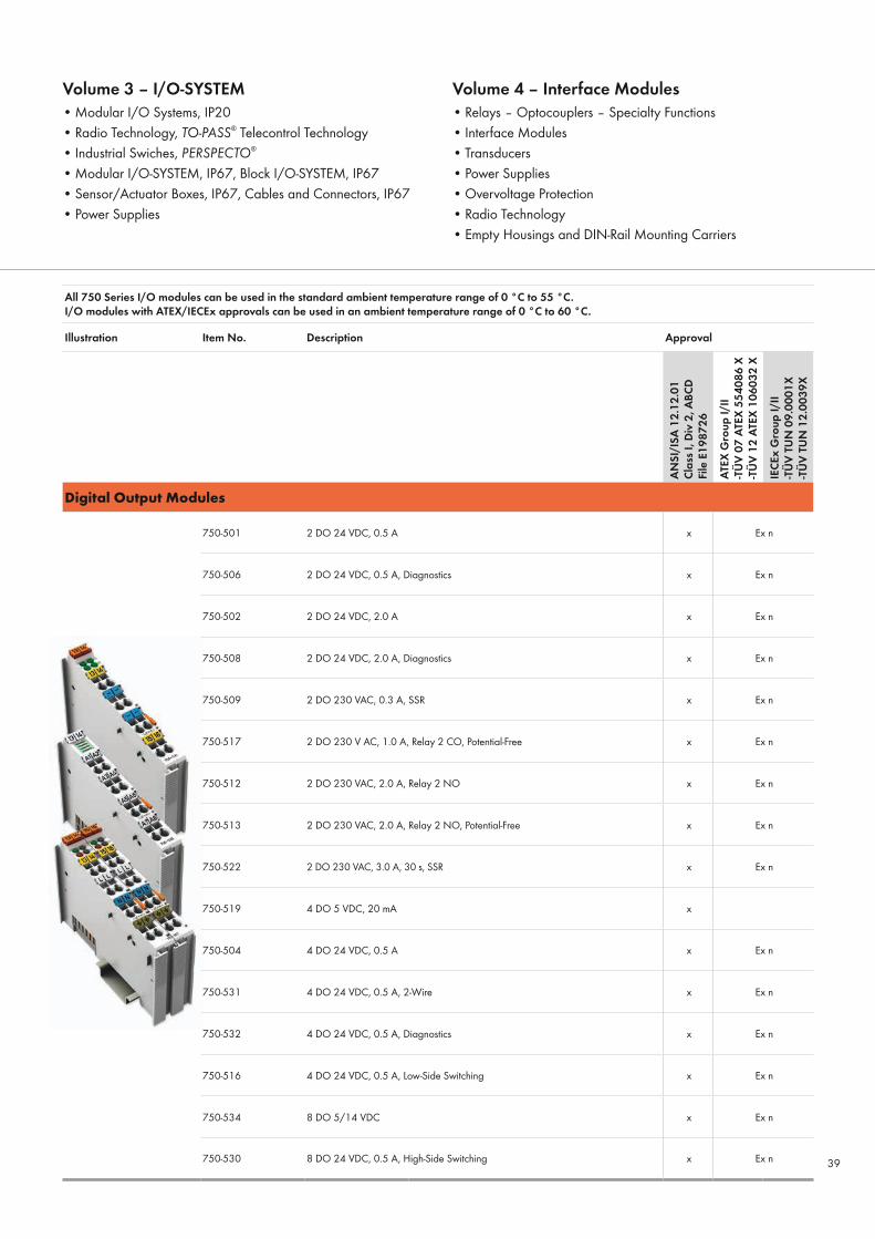
Digital Output Modules
750-501 2 DO 24 VDC, 0.5 A x Ex n
750-506 2 DO 24 VDC, 0.5 A, Diagnostics x Ex n
750-502 2 DO 24 VDC, 2.0 A x Ex n
750-508 2 DO 24 VDC, 2.0 A, Diagnostics x Ex n
750-509 2 DO 230 VAC, 0.3 A, SSR x Ex n
750-517 2 DO 230 V AC, 1.0 A, Relay 2 CO, Potential-Free x Ex n
750-512 2 DO 230 VAC, 2.0 A, Relay 2 NO x Ex n
750-513 2 DO 230 VAC, 2.0 A, Relay 2 NO, Potential-Free x Ex n
750-522 2 DO 230 VAC, 3.0 A, 30 s, SSR x Ex n
750-519 4 DO 5 VDC, 20 mA x
750-504 4 DO 24 VDC, 0.5 A x Ex n
750-531 4 DO 24 VDC, 0.5 A, 2-Wire x Ex n
750-532 4 DO 24 VDC, 0.5 A, Diagnostics x Ex n
750-516 4 DO 24 VDC, 0.5 A, Low-Side Switching x Ex n
750-534 8 DO 5/14 VDC x Ex n
750-530 8 DO 24 VDC, 0.5 A, High-Side Switching x Ex n
Volume 3 – I/O-SYSTEM • Modular I/O Systems, IP20• Radio Technology, TO-PASS® Telecontrol Technology• Industrial Swiches, PERSPECTO®
• Modular I/O-SYSTEM, IP67, Block I/O-SYSTEM, IP67• Sensor/Actuator Boxes, IP67, Cables and Connectors, IP67• Power Supplies
Volume 4 – Interface Modules• Relays – Optocouplers – Specialty Functions• Interface Modules• Transducers • Power Supplies• Overvoltage Protection• Radio Technology • Empty Housings and DIN-Rail Mounting Carriers
39

All 750 Series I/O modules can be used in the standard ambient temperature range of 0 °C to 55 °C.I/O modules with ATEX/IECEx approvals can be used in an ambient temperature range of 0 °C to 60 °C.
Illustration Item No. Description Approval
AN
SI/I
SA 1
2.12
.01
Clas
s I, D
iv 2
, ABC
D
File
E19
8726
ATEX
Gro
up I/
II-T
ÜV
07 A
TEX
5540
86 X
-TÜ
V 12
ATE
X 10
6032
X
IECE
x G
roup
I/II
-TÜ
V TU
N 0
9.00
01X
-TÜ
V TU
N 1
2.00
39X
Digital Output Modules
750-536 8 DO 24 VDC, 0.5 A, Low-Side Switching x Ex n
750-1515 8 DO 24 VDC, 0.5 A, 2-Wire, High-Side Switching x Ex n
750-537 8 DO 24 VDC, 0.5 A, Diagnostics x Ex n
750-1516 8 DO 24 VDC, 0.5 A, Low-Side Switching x Ex n
750-1504 16 DO 24 VDC, 0.5 A x Ex n
750-1500 16 DO 24 VDC, 0.5 A, Ribbon Cable x Ex n
750-1501 16 DI 24 VDC, 0.5 A, Ribbon Cable, Low-Side Switching x Ex n
750-1505 16 DO 24 VDC, 0.5 A, Low-Side Switching x Ex n
All 750 Series I/O modules can be used in the standard ambient temperature range of 0 °C to 55 °C.I/O modules with ATEX/IECEx approvals can be used in an ambient temperature range of 0 °C to 60 °C.
Illustration Item No. Description Approval
AN
SI/I
SA 1
2.12
.01
Clas
s I, D
iv 2
, ABC
D
File
E19
8726
ATEX
Gro
up I/
II-T
ÜV
07 A
TEX
5540
86 X
-TÜ
V 12
ATE
X 10
6032
X
IECE
x G
roup
I/II
-TÜ
V TU
N 0
9.00
01X
-TÜ
V TU
N 1
2.00
39X
Digital Input/Output Modules
750-1506 8 DI 8 DO 24 VDC, 0.5 A x Ex n
750-1502 8 DI 8 DO 24 VDC, 0.5 A, Ribbon Cable x Ex n40

All 750 Series I/O modules can be used in the standard ambient temperature range of 0 °C to 55 °C.I/O modules with ATEX/IECEx approvals can be used in an ambient temperature range of 0 °C to 60 °C.
Illustration Item No. Description Approval
AN
SI/I
SA 1
2.12
.01
Clas
s I, D
iv 2
, ABC
D
File
E19
8726
ATEX
Gro
up I/
II-T
ÜV
07 A
TEX
5540
86 X
-TÜ
V 12
ATE
X 10
6032
X
IECE
x G
roup
I/II
-TÜ
V TU
N 0
9.00
01X
-TÜ
V TU
N 1
2.00
39X
Analog Input Modules
750-456 2 AI ±10 VDC x Ex n
750-476 2 AI ±10 VDC ,16-Bit, S.-E. x Ex n
750-479 2 AI ±10 VDC, Differential Measurement Input x Ex n
750-477 2 AI 0–10 V AC/DC, Differential Input x Ex n
750-467 2 AI 0–10 VDC, S.-E. x Ex n
750-478 2 AI 0–10 VDC,16-Bit, S.-E. x Ex n
750-483 2 AI 0–30 VDC, Differential Measurement Input x Ex n
750-472 2 AI 0–20 mA, 16-Bit, S.-E. x Ex n
750-470 2 AI 0–20 mA,16-Bit, S.-E., S.-C. Protect. x Ex n
750-452 2 AI 0–20 mA, Differential Input x Ex n
750-480 2 AI 0–20 mA, Differential Measurement Input x Ex n
750-465 2 AI 0–20 mA, S.-E. x Ex n
750-482 2 AI 4–20 mA, 12-Bit, S.-E., HART x Ex n
750-474 2 AI 4–20 mA, 16-Bit, S.-E. x Ex n
750-473 2 AI 4–20 mA, 16-Bit, S.-E., S.-C. Protect. x Ex n
750-454 2 AI 4–20 mA, Differential Input x Ex n
Volume 3 – I/O-SYSTEM • Modular I/O Systems, IP20• Radio Technology, TO-PASS® Telecontrol Technology• Industrial Swiches, PERSPECTO®
• Modular I/O-SYSTEM, IP67, Block I/O-SYSTEM, IP67• Sensor/Actuator Boxes, IP67, Cables and Connectors, IP67• Power Supplies
Volume 4 – Interface Modules• Relays – Optocouplers – Specialty Functions• Interface Modules• Transducers • Power Supplies• Overvoltage Protection• Radio Technology • Empty Housings and DIN-Rail Mounting Carriers
41

All 750 Series I/O modules can be used in the standard ambient temperature range of 0 °C to 55 °C.I/O modules with ATEX/IECEx approvals can be used in an ambient temperature range of 0 °C to 60 °C.
Illustration Item No. Description Approval
AN
SI/I
SA 1
2.12
.01
Clas
s I, D
iv 2
, ABC
D
File
E19
8726
ATEX
Gro
up I/
II-T
ÜV
07 A
TEX
5540
86 X
-TÜ
V 12
ATE
X 10
6032
X
IECE
x G
roup
I/II
-TÜ
V TU
N 0
9.00
01X
-TÜ
V TU
N 1
2.00
39X
Analog Input Modules
750-492 2 AI 4–20 mA, Differential Measurement Input x Ex n
750-466 2 AI 4–20 mA, S.-E. x Ex n
750-475 2 AI 0–1 A AC/DC, Differential Input x Ex n
750-461 2 AI RTD x Ex n
750-469 2 AI TC, Diagnostics x Ex n
750-464 2/4 AI RTD, Freely Configurable x Ex n
750-457 4 AI ±10 VDC, S.-E. x Ex n
750-459 4 AI 0–10 VDC, S.-E. x Ex n
750-468 4 AI 0–10 VDC, S.-E. x Ex n
750-453 4 AI 0 – 20 mA S.E. x Ex n
750-455 4 AI 4–20 mA, S.-E. x Ex n
750-463 4 AI RTD, -30 °C … +150 °C Ex n
750-493 3-Phase Power Measurement Module Ex n
750-494 3-Phase Power Measurement Module, Harmonic Analysis Ex n
42

All 750 Series I/O modules can be used in the standard ambient temperature range of 0 °C to 55 °C.I/O modules with ATEX/IECEx approvals can be used in an ambient temperature range of 0 °C to 60 °C.
Illustration Item No. Description Approval
AN
SI/I
SA 1
2.12
.01
Clas
s I, D
iv 2
, ABC
D
File
E19
8726
ATEX
Gro
up I/
II-T
ÜV
07 A
TEX
5540
86 X
-TÜ
V 12
ATE
X 10
6032
X
IECE
x G
roup
I/II
-TÜ
V TU
N 0
9.00
01X
-TÜ
V TU
N 1
2.00
39X
Analog Output Modules
750-550 2 AO 0–10 VDC x Ex n
750-560 2 AO 0–10 VDC, 10-Bit, 10 mA 24 V x Ex n
750-556 2 AO ±10 VDC x Ex n
750-562 2 AO 0/±10 VDC, 16-Bit x Ex n
750-563 2 AO 0/4–20 mA, 6–18 VDC, 16-Bit x Ex n
750-552 2 AO 0–20 mA x Ex n
750-554 2 AO 4–20 mA x Ex n
750-559 4 AO 0–10 VDC x Ex n
750-557 4 AO ±10 VDC x Ex n
750-553 4 AO 0–20 mA x Ex n
750-555 4 AO 4–20 mA x Ex n
Volume 3 – I/O-SYSTEM • Modular I/O Systems, IP20• Radio Technology, TO-PASS® Telecontrol Technology• Industrial Swiches, PERSPECTO®
• Modular I/O-SYSTEM, IP67, Block I/O-SYSTEM, IP67• Sensor/Actuator Boxes, IP67, Cables and Connectors, IP67• Power Supplies
Volume 4 – Interface Modules• Relays – Optocouplers – Specialty Functions• Interface Modules• Transducers • Power Supplies• Overvoltage Protection• Radio Technology • Empty Housings and DIN-Rail Mounting Carriers
43

All 750 Series I/O modules can be used in the standard ambient temperature range of 0 °C to 55 °C.I/O modules with ATEX/IECEx approvals can be used in an ambient temperature range of 0 °C to 60 °C.
Illustration Item No. Description Approval
AN
SI/I
SA 1
2.12
.01
Clas
s I, D
iv 2
, ABC
D
File
E19
8726
ATEX
Gro
up I/
II-T
ÜV
07 A
TEX
5540
86 X
-TÜ
V 12
ATE
X 10
6032
X
IECE
x G
roup
I/II
-TÜ
V TU
N 0
9.00
01X
-TÜ
V TU
N 1
2.00
39X
Specialty Modules
750-404 1-Channel Up/Down Counter, 100 kHz x Ex n
750-645 2 AI/2 DO VIB VRMS/SPM Multi x Ex n
750-511 2 DO 24 VDC, 0.1 A, Pulse Width x Ex n
750-638 2-Channel Up/Down Counter, 500 Hz x Ex n
750-655 AS Interface Master x Ex n
750-644 Bluetooth® RF Transceiver x Ex n
750-641 DALI / DSI Master Module x Ex n
750-635 Digital Pulse Interface x Ex n
750-642 Radio Receiver I/O Module x Ex n
750-637 Incremental Encoder Interface, 32-Bit x Ex n
750-643 MP Bus Master Module x Ex n
750-652 RS-232/RS-485, Freely Configurable x Ex n
750-650 RS-232-C Interface x Ex n
750-653 RS-485 Interface x Ex n
750-640 RTC Module x Ex n
750-630 SSI Transmitter Interface x Ex n44

All 750 Series I/O modules can be used in the standard ambient temperature range of 0 °C to 55 °C.I/O modules with ATEX/IECEx approvals can be used in an ambient temperature range of 0 °C to 60 °C.
Illustration Item No. Description Approval
AN
SI/I
SA 1
2.12
.01
Clas
s I, D
iv 2
, ABC
D
File
E19
8726
ATEX
Gro
up I/
II-T
ÜV
07 A
TEX
5540
86 X
-TÜ
V 12
ATE
X 10
6032
X
IECE
x G
roup
I/II
-TÜ
V TU
N 0
9.00
01X
-TÜ
V TU
N 1
2.00
39X
Specialty Modules
750-671 Stepper Controller 24 V, 1.5 A x Ex n
750-670 Stepper Controller 24 V, RS-422, 20 mA x Ex n
750-651 TTY Interface x
All 750 Series I/O modules can be used in the standard ambient temperature range of 0 °C to 55 °C.I/O modules with ATEX/IECEx approvals can be used in an ambient temperature range of 0 °C to 60 °C.
Illustration Item No. Description Approval
AN
SI/I
SA 1
2.12
.01
Clas
s I, D
iv 2
, ABC
D
File
E19
8726
ATEX
Gro
up I/
II-T
ÜV
07 A
TEX
5540
86 X
-TÜ
V 12
ATE
X 10
6032
X
IECE
x G
roup
I/II
-TÜ
V TU
N 0
9.00
01X
-TÜ
V TU
N 1
2.00
39X
System Modules
750-612 0−230 V AC/DC Power Supply x Ex n
750-615 120 VAC Power Supply, Fuse x Ex n
750-609 230 VAC Power Supply, Fuse x Ex n
750-611 230 VAC Power Supply, Fuse, Diagnostics x Ex n
750-602 24 VDC Power Supply x Ex n
750-601 24 VDC Power Supply, Fuse x Ex n
750-610 24 VDC Power Supply, Fuse, Diagnostics x Ex n
Volume 3 – I/O-SYSTEM • Modular I/O Systems, IP20• Radio Technology, TO-PASS® Telecontrol Technology• Industrial Swiches, PERSPECTO®
• Modular I/O-SYSTEM, IP67, Block I/O-SYSTEM, IP67• Sensor/Actuator Boxes, IP67, Cables and Connectors, IP67• Power Supplies
Volume 4 – Interface Modules• Relays – Optocouplers – Specialty Functions• Interface Modules• Transducers • Power Supplies• Overvoltage Protection• Radio Technology • Empty Housings and DIN-Rail Mounting Carriers
45
All 750 Series I/O modules can be used in the standard ambient temperature range of 0 °C to 55 °C.I/O modules with ATEX/IECEx approvals can be used in an ambient temperature range of 0 °C to 60 °C.
Illustration Item No. Description Approval
AN
SI/I
SA 1
2.12
.01
Clas
s I, D
iv 2
, ABC
D
File
E19
8726
ATEX
Gro
up I/
II-T
ÜV
07 A
TEX
5540
86 X
-TÜ
V 12
ATE
X 10
6032
X
IECE
x G
roup
I/II
-TÜ
V TU
N 0
9.00
01X
-TÜ
V TU
N 1
2.00
39X
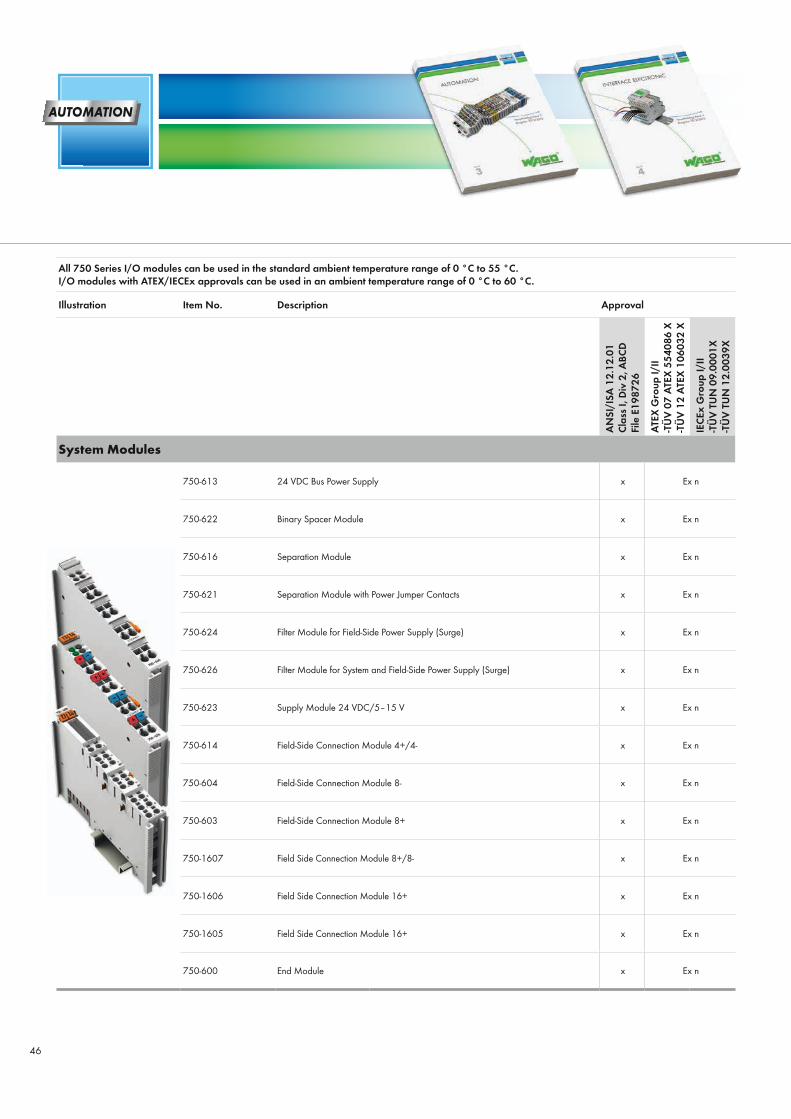
System Modules
750-613 24 VDC Bus Power Supply x Ex n
750-622 Binary Spacer Module x Ex n
750-616 Separation Module x Ex n
750-621 Separation Module with Power Jumper Contacts x Ex n
750-624 Filter Module for Field-Side Power Supply (Surge) x Ex n
750-626 Filter Module for System and Field-Side Power Supply (Surge) x Ex n
750-623 Supply Module 24 VDC/5–15 V x Ex n
750-614 Field-Side Connection Module 4+/4- x Ex n
750-604 Field-Side Connection Module 8- x Ex n
750-603 Field-Side Connection Module 8+ x Ex n
750-1607 Field Side Connection Module 8+/8- x Ex n
750-1606 Field Side Connection Module 16+ x Ex n
750-1605 Field Side Connection Module 16+ x Ex n
750-600 End Module x Ex n
46

Illustration Item No. Descrip-tion Technical Data
Tempe- rature Range
Approval Degree of Protection
-10°
C ...
+70
°C
ANSI
/ IS
A 12
.12.
01
DEM
KO 1
2 AT
EX 0
9312
67X
IECE
x U
L 10.
0006
X
Clas
s I D
iv 2
ABCD
T4A
Clas
s I D
iv 2
ABCD
T4
Clas
s I D
iv 2
ABCD
T3C
II3G
Ex
nA II
C T4
Gc
II3G
Ex
nA n
C IIC
T4
Gc
II3G
Ex
nA n
C IIC
T3
Gc
EPSITRON® ECO Power
787-712 787 Series110–240 VAC input, 24 VDC/2.5 A output,adjustable output voltage, open-circuit and short-circuit protected,LED status indication
x x x*1
xx - - x - -
787-722 787 Series110–240 VAC input, 24 VDC/5 A output,adjustable output voltage, open-circuit and short-circuit protected,LED status indication
x x x*1
x- x - - x -
787-732 787 Series110–240 VAC input, 24 VDC/10 A output,adjustable output voltage, open-circuit and short-circuit protected,LED status indication
x x x*1
x- - x - - x
*1 = pending
Volume 3 – I/O-SYSTEM • Modular I/O Systems, IP20• Radio Technology, TO-PASS® Telecontrol Technology• Industrial Swiches, PERSPECTO®
• Modular I/O-SYSTEM, IP67, Block I/O-SYSTEM, IP67• Sensor/Actuator Boxes, IP67, Cables and Connectors, IP67• Power Supplies
Volume 4 – Interface Modules• Relays – Optocouplers – Specialty Functions• Interface Modules• Transducers • Power Supplies• Overvoltage Protection• Radio Technology • Empty Housings and DIN-Rail Mounting Carriers
47

0888
-013
1/02
00-6
901
- EEX
BRO
CH
URE
2.0
US
- 03/
14 -
Prin
ted
in G
erm
any
- Sub
ject
to d
esig
n ch
ange
s
WAGO Kontakttechnik GmbH & Co. KGPostfach 2880 · 32385 MindenHansastraße 27 · 32423 MindenPhone:Headquarters +49 571/887 - 0Sales +49 571/887 - 222Order Service +49 571/887 - 333Technical Support +49 571/887 - 555Fax: +49 571/887 - 169E-mail: [email protected]: www.wago.com
www.wago.com/ex


