247

Tetra Tech EM Inc.
Hazardous Waste Combustion UnitPermitting Manual
How To Conduct Trial Burn Test Oversight
COMPONENT 4
UNITED STATES
EN
VIRO
NM
ENTALPROTECTIO
NA
GEN
CY
U.S. EPA Region 6 Center for CombustionScience and Engineering
5 6 72 31 4

COMPONENT FOUR
HOW TO CONDUCT TRIAL BURN TESTOVERSIGHT
JANUARY 1998

COMPONENT 4—HOW TO CONDUCT TRIAL BURN TEST OVERSIGHT
U.S. EPA Region 6Center for Combustion Science and Engineering 4-i
CONTENTS
Section Page
ABBREVIATIONS AND ACRONYMS . . . . . . . . . . . . . . . . . . . . . . . . . . . . . . . . . . . . . . . . . . . . . . 4-iv
BIBLIOGRAPHY . . . . . . . . . . . . . . . . . . . . . . . . . . . . . . . . . . . . . . . . . . . . . . . . . . . . . . . . . . . . . . . 4-v
1.0 OVERVIEW OF TRIAL BURN TEST OVERSIGHT . . . . . . . . . . . . . . . . . . . . . . . . . . . . . 4-1
2.0 PREPARATION ACTIVITIES . . . . . . . . . . . . . . . . . . . . . . . . . . . . . . . . . . . . . . . . . . . . . . . 4-3
2.1 REVIEWING THE TRIAL BURN PLAN AND QUALITY ASSURANCEPROJECT PLAN . . . . . . . . . . . . . . . . . . . . . . . . . . . . . . . . . . . . . . . . . . . . . . . . . . . 4-5
2.1.1 Gathering General Facility Information . . . . . . . . . . . . . . . . . . . . . . . . . . . . . 4-72.1.2 Reviewing Proposed Stack Gas Sampling Procedures . . . . . . . . . . . . . . . . . . 4-92.1.3 Reviewing Waste Feed and Air Pollution Control Device Effluent Sampling
Information . . . . . . . . . . . . . . . . . . . . . . . . . . . . . . . . . . . . . . . . . . . . . . . . 4-10
2.2 DEVELOPING A HEALTH AND SAFETY PLAN . . . . . . . . . . . . . . . . . . . . . . . . 4-11
3.0 CONDUCTING FIELD ACTIVITIES . . . . . . . . . . . . . . . . . . . . . . . . . . . . . . . . . . . . . . . . 4-16
3.1 CONDUCTING A PRETEST MEETING . . . . . . . . . . . . . . . . . . . . . . . . . . . . . . . 4-183.2 CONDUCTING A PRETEST FACILITY SURVEY . . . . . . . . . . . . . . . . . . . . . . . 4-193.3 REVIEWING EQUIPMENT CALIBRATION RECORDS . . . . . . . . . . . . . . . . . . 4-21
3.3.1 Reviewing Stack Sampling Equipment Calibration Records . . . . . . . . . . . . . 4-233.3.2 Reviewing Feed Spiking Equipment Calibration Records . . . . . . . . . . . . . . . 4-263.3.3 Reviewing Process Control Equipment Calibration Records . . . . . . . . . . . . 4-303.3.4 Reviewing Continuous Emission Monitoring System Calibration
Records . . . . . . . . . . . . . . . . . . . . . . . . . . . . . . . . . . . . . . . . . . . . . . . . . . . 4-433.3.5 Reviewing Field Laboratory Instrumentation Calibration Records . . . . . . . . 4-48
3.4 OBSERVING STACK SAMPLING ACTIVITIES . . . . . . . . . . . . . . . . . . . . . . . . 4-49
3.4.1 Reviewing Sampling Port Location . . . . . . . . . . . . . . . . . . . . . . . . . . . . . . . 4-523.4.2 Reviewing Cyclonic Flow Measurements . . . . . . . . . . . . . . . . . . . . . . . . . . 4-563.4.3 Reviewing Traverse Point Location . . . . . . . . . . . . . . . . . . . . . . . . . . . . . . . 4-593.4.4 Reviewing Sampling Train Assembly . . . . . . . . . . . . . . . . . . . . . . . . . . . . . 4-613.4.5 Observing Leak Checks Prior To Sampling . . . . . . . . . . . . . . . . . . . . . . . . . 4-633.4.6 Observing Sampling Train Temperatures . . . . . . . . . . . . . . . . . . . . . . . . . . 4-653.4.7 Observing the Field Data Logsheet . . . . . . . . . . . . . . . . . . . . . . . . . . . . . . . 4-683.4.8 Observing Leak Checks During Sampling . . . . . . . . . . . . . . . . . . . . . . . . . . 4-713.4.9 Observing Sampling Train Disassembly . . . . . . . . . . . . . . . . . . . . . . . . . . . 4-723.4.10 Completing Stack Sampling Checklists . . . . . . . . . . . . . . . . . . . . . . . . . . . . 4-73

COMPONENT 4—HOW TO CONDUCT TRIAL BURN TEST OVERSIGHT
U.S. EPA Region 6Center for Combustion Science and Engineering 4-ii
CONTENTS (Continued)
Section Page
3.5 OBSERVING WASTE FEED AND AIR POLLUTION CONTROL DEVICEEFFLUENT SAMPLING . . . . . . . . . . . . . . . . . . . . . . . . . . . . . . . . . . . . . . . . . . . . 4-78
3.6 OBSERVING PROCESS OPERATION ACTIVITIES . . . . . . . . . . . . . . . . . . . . . 4-823.7 OBSERVING SAMPLE RECOVERY . . . . . . . . . . . . . . . . . . . . . . . . . . . . . . . . . . 4-853.8 COLLECTING TRIAL BURN TEST INFORMATION . . . . . . . . . . . . . . . . . . . . . 4-883.9 CONDUCTING DAILY MEETINGS . . . . . . . . . . . . . . . . . . . . . . . . . . . . . . . . . . 4-903.10 CONDUCTING FIELD DOCUMENTATION ACTIVITIES . . . . . . . . . . . . . . . . . 4-913.11 OBSERVING AUDIT GAS SAMPLING . . . . . . . . . . . . . . . . . . . . . . . . . . . . . . . . 4-93
4.0 PREPARING THE OVERSIGHT REPORT . . . . . . . . . . . . . . . . . . . . . . . . . . . . . . . . . . . . 4-96
EXHIBITS
Exhibit Page
2.1.1-1 CHECKLIST FOR GATHERING GENERAL FACILITY INFORMATION . . . . . . . . . . 4-82.2-1 EXAMPLE SUMMARY HEALTH AND SAFETY PLAN HAZARDOUS
SUBSTANCES SECTION . . . . . . . . . . . . . . . . . . . . . . . . . . . . . . . . . . . . . . . . . . . . . . . 4-133.3.1-1 BLANK DIGITAL TEMPERATURE INDICATOR CALIBRATION FORM . . . . . . . . . 4-253.3.2-1 SPIKING PUMP CALIBRATION FORM . . . . . . . . . . . . . . . . . . . . . . . . . . . . . . . . . . . . 4-283.3.2-2 SPIKING CHEMICAL CERTIFICATE OF ANALYSIS . . . . . . . . . . . . . . . . . . . . . . . . . 4-293.3.3-1 EXAMPLE PROCESS CONTROL EQUIPMENT CALIBRATION FORM . . . . . . . . . . 4-323.3.3-2 INFRARED THERMOMETER CALIBRATION REPORT . . . . . . . . . . . . . . . . . . . . . . 4-333.3.3-3 EXAMPLE THERMOCOUPLE TEMPERATURE TRANSMITTER CALIBRATION
RECORD . . . . . . . . . . . . . . . . . . . . . . . . . . . . . . . . . . . . . . . . . . . . . . . . . . . . . . . . . . . . 4-343.3.3-4 EXAMPLE DIFFERENTIAL PRESSURE FLOW TRANSMITTER CALIBRATION
RECORD . . . . . . . . . . . . . . . . . . . . . . . . . . . . . . . . . . . . . . . . . . . . . . . . . . . . . . . . . . . . 4-373.3.3-5 EXAMPLE MISCELLANEOUS FLOW TRANSMITTER CALIBRATION RECORD . 4-403.3.4-1 EXAMPLE CEMS MULTIPOINT CALIBRATION DATA SHEET . . . . . . . . . . . . . . . . 4-453.3.4-2 EXAMPLE PERFORMANCE SPECIFICATION TEST RESULTS . . . . . . . . . . . . . . . . 4-463.3.4-3 EXAMPLE RELATIVE ACCURACY TEST RESULTS . . . . . . . . . . . . . . . . . . . . . . . . 4-473.4.1-1 EXAMPLE STACK DIAGRAM . . . . . . . . . . . . . . . . . . . . . . . . . . . . . . . . . . . . . . . . . . . 4-553.4.2-1 EXAMPLE CYCLONIC FLOW CHECK SHEET . . . . . . . . . . . . . . . . . . . . . . . . . . . . . . 4-573.4.3-1 EXAMPLE PRELIMINARY VELOCITY TRAVERSE DATA AND SAMPLING
LOCATION DATA SHEET . . . . . . . . . . . . . . . . . . . . . . . . . . . . . . . . . . . . . . . . . . . . . . 4-603.4.7-1 EXAMPLE FIELD DATA SHEET . . . . . . . . . . . . . . . . . . . . . . . . . . . . . . . . . . . . . . . . . 4-693.4.10-1 METHOD 0010 SEMIVOLATILE SAMPLING CHECKLIST . . . . . . . . . . . . . . . . . . . . 4-743.5-1 EXAMPLE WASTE FEED SAMPLE LOGSHEET . . . . . . . . . . . . . . . . . . . . . . . . . . . . 4-803.5-2 EXAMPLE CHAIN-OF-CUSTODY RECORD . . . . . . . . . . . . . . . . . . . . . . . . . . . . . . . . 4-813.7-1 METHOD 0030 VOLATILE ORGANIC SAMPLING TRAIN RECOVERY
CHECKLIST . . . . . . . . . . . . . . . . . . . . . . . . . . . . . . . . . . . . . . . . . . . . . . . . . . . . . . . . . . 4-863.8-1 EXAMPLE FIELD DATA CALCULATION SHEET . . . . . . . . . . . . . . . . . . . . . . . . . . . 4-89

COMPONENT 4—HOW TO CONDUCT TRIAL BURN TEST OVERSIGHT
U.S. EPA Region 6Center for Combustion Science and Engineering 4-iii
ATTACHMENTS
Attachments
A METHOD 0010 SEMIVOLATILE POHC AND PIC ORGANICS SAMPLING CHECKLISTB METHOD 0010 SEMIVOLATILE POHC AND PIC ORGANICS SAMPLE RECOVERY
CHECKLISTC METHOD 0012 MULTIPLE METALS SAMPLING CHECKLISTD METHOD 0012 MULTIPLE METALS SAMPLE RECOVERY CHECKLISTE METHOD 0013 HEXAVALENT CHROMIUM SAMPLING CHECKLISTF METHOD 0013 HEXAVALENT CHROMIUM SAMPLE RECOVERY CHECKLISTG METHOD 23 PCDD/PCDF SAMPLING CHECKLISTH METHOD 23 PCDD/PCDF SAMPLE RECOVERY CHECKLISTI METHOD 0030 VOLATILE ORGANICS SAMPLING TRAIN CHECKLISTJ METHOD 0030 VOLATILE ORGANICS SAMPLING TRAIN SAMPLE
RECOVERY CHECKLISTK METHOD 0040 TOTAL ORGANIC TEDLAR BAG SAMPLING CHECKLISTL METHOD 0040 TOTAL ORGANIC TEDLAR BAG SAMPLE RECOVERY
CHECKLISTM METHOD 0050 PARTICULATE/HCl/Cl SAMPLING CHECKLIST2
N METHOD 0050 PARTICULATE/HCl/Cl SAMPLE RECOVERY CHECKLIST2
O METHOD 0060 MULTIPLE METALS SAMPLING CHECKLISTP METHOD 0060 MULTIPLE METALS SAMPLE RECOVERY CHECKLISTQ METHOD 0061 HEXAVALENT CHROMIUM SAMPLING CHECKLISTR METHOD 0061 HEXAVALENT CHROMIUM SAMPLE RECOVERY CHECKLISTS METHOD 0031 VOLATILE ORGANICS SAMPLING TRAIN CHECKLISTT METHOD 0031 VOLATILE ORGANICS SAMPLING TRAIN SAMPLE
RECOVERY CHECKLISTU METHOD 0023A PCDD/PCDF SAMPLING CHECKLISTV METHOD 0023A PCDD/PCDF SAMPLE RECOVERY CHECKLISTW METHOD 0011 FORMALDEHYDE (ALDEHYDE AND KETONE) SAMPLING
CHECKLISTX METHOD 0011 FORMALDEHYDE (ALDEHYDE AND KETONE) SAMPLE RECOVERY
CHECKLISTY HOW TO CONDUCT TRIAL BURN TEST OVERSIGHT REVIEW CHECKLIST

COMPONENT 4—HOW TO CONDUCT TRIAL BURN TEST OVERSIGHT
U.S. EPA Region 6Center for Combustion Science and Engineering 4-iv
ABBREVIATIONS AND ACRONYMS
APCS Air pollution control systemBIF Boiler and industrial furnaceCEMS Continuous emissions monitoring system40 CFR Title 40, Code of Federal RegulationsEC Degrees CelsiusCO Carbon monoxideDACS Data acquisition control systemDAR Data acquisition recorderDRE Destruction and removal efficiencyDTI Digital temperature indicatorEF Degrees Fahrenheitgpm gallons per minuteGC/FID Gas chromatograph/flame ionization detectorHAF Halogen acid furnaceHg MercuryHSP Health and safety planlb/hr pounds per hourLEL Lower explosive limitmg/m milligrams per cubic meter3
mL millilitersO Oxygen2
OSHA Occupational Safety & Health AdministrationOSWER Office of Solid Waste and Emergency ResponsePCDD/PCDF Polychlorinated dibenzopdioxin/polychlorinated dibenzofuranPPE Personal protection equipmentppm parts per millionPOHC Principal organic hazardous constituentQA Quality assuranceQAPP Quality assurance project planQA/QC Quality assurance/quality controlRBP Risk burn planRCRA Resource Conservation and Recovery ActRTP Research Triangle ParkSOP Standard operating procedureSVOC Semivolatile organic compoundTBO Trial burn oversightTBP Trial burn planUB Utility boilerU.S. EPA U.S. Environmental Protection AgencyVOA Volatile organic analysisVOST Volatile organic sampling train
COMPONENT 4—HOW TO CONDUCT TRIAL BURN TEST OVERSIGHT
U.S. EPA Region 6Center for Combustion Science and Engineering 4-v
BIBLIOGRAPHY
U.S. Environmental Protection Agency (EPA). “Appendix A — Test Methods.” 40 CFR Part 60,Appendix A.
U.S. EPA. “Appendix B — Performance Specifications.” 40 CFR Part 60, Appendix B.
U.S. EPA. “Appendix F to Part 60 — Quality Assurance Procedures.” 40 CFR Part 60, Appendix F.
U.S. EPA. 1977. “Quality Assurance (QA) Handbook for Air Pollution Measurement Systems,Volume III: Stationary Source-Specific Methods.” EPA-600/4-77-027B.
U.S. EPA. 1986. “Practical Guide — Trial Burns for Hazardous Waste Incinerators.” Office ofResearch and Development. Cincinnati, Ohio. EPA/600/2-86/050. April.
U.S. EPA. 1989. “Trial Burn Observation Guide.” Office of Solid Waste and Emergency Response(OSWER). Washington, D.C. EPA/530-SW-89-027. March.
U.S. EPA. 1989. “Handbook: Hazardous Waste Incineration Measurement Guidance Manual.” OSWER. Washington, D.C. EPA/625/6-89/021. June.
U.S. EPA. 1990. “Handbook: Quality Assurance/Quality Control (QA/QC) Procedures for HazardousWaste Incineration.” OSWER. Washington, D.C. EPA-625/6-89-023. January.
U.S. EPA. 1990 “Methods Manual for Compliance with BIF Regulations.” OSWER. Washington,D.C. EPA/530-SW-91-010. December.
U.S. EPA. 1993. “Regulatory Interpretation of Automatic Waste Feed Cutoffs in Boilers and IndustrialFurnaces.” OSWER.
U.S. EPA. 1994. “Memorandum on Trial Burns.” OSWER. Washington, D.C. EPA530-F-94-023. July.
U.S. EPA. 1996. “Test Methods for Evaluating Solid Waste Physical/Chemical Methods (SW-846),Third Edition.” December.
U.S. EPA. 1997. “Generic Quality Assurance Project Plan (QAPP).” Center for Combustion Scienceand Engineering, Multimedia Planning and Permitting Division, U.S. EPA Region 6. Dallas,Texas. December.
U.S. EPA. 1997. “Generic Trial Burn Plan (TBP).” Center for Combustion Science and Engineering,Multimedia Planning and Permitting Division, U.S. EPA Region 6. Dallas, Texas. December.

COMPONENT 4—HOW TO CONDUCT TRIAL BURN TEST OVERSIGHT
U.S. EPA Region 6Center for Combustion Science and Engineering 4-1
1.0 OVERVIEW OF TRIAL BURN TEST OVERSIGHT
Regulations: No regulations are applicable to this section of the manual.
Guidance: No specific references are applicable to this section of the manual.
Explanation: To ensure that the trial burn or risk burn is conducted in accordance with theapproved trial burn plan (TBP) or risk burn plan (RBP), the quality assuranceproject plan (QAPP), and the standard operating procedures (SOP) identified invarious regulatory and guidance documents, comprehensive trial burn oversight(TBO) is conducted. Findings of the trial burn oversight determine whether trialburn results are acceptable.
Stack gas sampling and recovery checklists that can be used as tools in conductingtrial burn test oversight are included as Attachments A through X to thiscomponent of the Hazardous Waste Combustion Unit Permitting Manual. Attachment Y is a checklist that an observer may use in the field to ensure that allnecessary activities are completed. This checklist summarizes all importantaspects of every section in this component.
Check For: Before mobilizing to the facility for oversight, the observer should be familiarwith:
“ Preparation activities
“ Conducting field activities
“ Writing the TBO report
“ Stack gas sampling and recovery checklists (Attachments A through X)
“ TBO checklist (Attachment Y)
Example Situation: XYZ Company submitted to U.S. EPA (1) destruction and removal efficiency(DRE) burn plans for the utility boiler (UB) and the halogen acid furnace (HAF),(2) RBPs for the UB and the HAF, and (3) a multimedia risk assessment workplan for the UB and the HAF. U.S. EPA has approved the TBPs for both boilersand requested that the XYZ Company provide additional information to documenttypes of wastes to be combusted in the UB and the HAF during the risk burn,representing worst-case waste. In response to U.S. EPA’s request for information,XYZ Company certified that the facility will combust worst-case waste streamsand will also spike additional amounts of higher-risk compounds to ensure that aworst-case waste situation exists during the risk burn. After reviewing theinformation, U.S. EPA approved the RBPs for the UB and the HAF.
Lois and Clark of Metropolis were selected to conduct oversight of trial burntesting at XYZ Company. Before mobilizing to the facility, Lois and Clarkreviewed the DRE burn plan and RBPs and were informed of (1) the type anddesign of BIF units to be tested, (2) types of tests to be performed, (3) samples to

COMPONENT 4—HOW TO CONDUCT TRIAL BURN TEST OVERSIGHT
U.S. EPA Region 6Center for Combustion Science and Engineering 4-2
be collected, (4) sampling procedures to be followed, and (5) process operatingconditions that would be maintained during the tests. Lois and Clark prepared anHSP that addressed all applicable regulatory requirements, personnelresponsibilities, personal protective equipment (PPE), and health and safety andemergency response procedures.
Lois and Clark conducted oversight of the trial burn that included (1) auditingequipment calibration records, (2) observing the sampling activities and processoperating conditions, (3) evaluating conformance with procedures described inapproved burn plans, (4) recording observations, and (5) collecting processoperating data and field logsheets. Lois and Clark returned to Metropolis andwrote a report to document stack sampling activities, process operating conditions,and observation and oversight activities.
Example Action: U.S. EPA will use the oversight report provided by Lois and Clark to(1) determine the acceptability of the DRE and risk burn tests, (2) evaluate thetrial burn and risk burn reports, and (3) prepare permit conditions based on theDRE and risk burn test conditions.
Notes:

COMPONENT 4—HOW TO CONDUCT TRIAL BURN TEST OVERSIGHT
U.S. EPA Region 6Center for Combustion Science and Engineering 4-3
2.0 PREPARATION ACTIVITIES
Regulation: No regulations are applicable to this section of the manual.
Guidance: No specific references are applicable to this section of the manual.
Explanation: Trial burn oversight consists of several prefield activities, including (1) developinga health and safety plan (HSP), (2) reviewing the TBP, (3) contacting facility trialburn personnel, (4) obtaining audit gas samples, and (5) mobilizing to the field. To ensure that the trial burn is conducted in strict accordance with the approvedTBP and that the data collected are of adequate quality to establish permitconditions that protect human health and the environment, members of theoversight team should familiarize themselves with the TBP, RBP, and QAPP. Toensure oversight safety, a site-specific HSP that details site hazards and providesroutine and emergency safety procedures should be developed prior to mobilizingto the field.
Check For: Complete the following tasks before arriving at the facility to conduct trial burnoversight:
“ Review TBP
“ Review RBP
“ Review QAPP
“ Prepare a site-specific HSP
“ Collect appropriate stack gas sampling and recovery checklists to becompleted on site (see attachments)
“ Gather appropriate health and safety equipment
Sections 2.1 and 2.2 describe the above items in detail.
Example Situation: Lois and Clark review the TBP, RBP, and QAPP thoroughly in accordance withprocedures suggested in Component 1—How to Review a Trial Burn Plan andComponent 2—How to Review a Quality Assurance Project Plan. After thereview of the TBP, RBP, and QAPP have been reviewed, Lois and Clark collectappropriate stack gas sampling and recovery checklists to be completed during thetrial burn. Clark identifies test site hazards and prepares a list of hazardouschemicals present at the test site along with their concentrations. Lois and Clarkmake sure that oversight equipment includes field notebook, hard hat, steel-toedboots, and flame resistant coveralls. Lois prepares a site-specific HSP thataddresses routine and emergency safety procedures and the PPE required for thetrial burn. Lois and Clark then make travel arrangements to arrive at the facility.
Example Comments: Trial burns often pose both unique and challenging field problems. To resolvethese issues promptly and effectively, the oversight team may need to refer to

COMPONENT 4—HOW TO CONDUCT TRIAL BURN TEST OVERSIGHT
U.S. EPA Region 6Center for Combustion Science and Engineering 4-4
numerous guidance documents, contact appropriate regulatory personnel, or both. The oversight team should carry to the field various guidance documents andnames and telephone numbers of the regulatory personnel who are experienced intrial burn observations and related issues.
Notes:

COMPONENT 4—HOW TO CONDUCT TRIAL BURN TEST OVERSIGHT
U.S. EPA Region 6Center for Combustion Science and Engineering 4-5
2.1 REVIEWING THE TRIAL BURN PLAN AND QUALITY ASSURANCE PROJECTPLAN
Regulation: No regulations are applicable to this section of the manual.
Guidance: No specific references are applicable to this section of the manual.
Explanation: To ensure thorough oversight of a trial burn, it is important to review andunderstand the TBP, RBP, and QAPP before mobilizing the oversight team to thefield. Specifically, the oversight personnel should complete the portions of theoversight checklist that can be filled out before the trial burn begins.
Check for: Confirm that all members of the oversight team understand the following:
“ General facility information
“ Proposed stack gas sampling procedures
“ Proposed waste feed and process residuals sampling procedures
Example Situation: Clark reads the Project Organization section of the TBP as follows:
“ABC Environmental, under contract to XYZ Company, will be conducting thetrial burn and will provide personnel experienced with Resource Conservation andRecovery Act (RCRA) methodologies, support tasks, and Occupational Safety andHealth Administration (OSHA) safety standards. The project leader willcoordinate services related to the trial burn and will be the primary contact withXYZ Company. Mr. Any Joe of ABC Environmental will act as an independentthird-party auditor of the trial burn.”
Does the Project Organization section of the TBP provide all necessaryinformation?
Example Action: To ensure the highest quality results for stack gas and waste feed samples, it isrequired that certified laboratories be used to analyze samples. The ProjectOrganization section of the trial burn plan does not identify the laboratoryresponsible for analyzing samples collected during the trial burn. Clark asks Loisto add this observation to the list of items that require additional information fromthe facility. Clark also notices that the project organization identifies a member ofthe stack testing company as the QA Officer. Since the QA Officer is notindependent of the sample collection team, a potential conflict of interest isidentified. Clark notified the U.S. EPA project leader. The U.S. EPA projectleader discusses the issue with the facility and suggests the organization chart berevised to make the QA Officer independent of the stack sampling crew. If thefacility fails to follow the direction of the U.S. EPA project leader, Lois and Clarknow are solely responsible for checking the quality of the data.

COMPONENT 4—HOW TO CONDUCT TRIAL BURN TEST OVERSIGHT
U.S. EPA Region 6Center for Combustion Science and Engineering 4-6
Notes:

COMPONENT 4—HOW TO CONDUCT TRIAL BURN TEST OVERSIGHT
U.S. EPA Region 6Center for Combustion Science and Engineering 4-7
2.1.1 Gathering General Facility Information
Regulation: No regulations are applicable to this section of the manual.
Guidance: No specific references are applicable to this section of the manual.
Explanation: The checklist below shows general facility information that must be compiled fromthe TBP or RBP. A checklist that may assist in compiling a summary of generalfacility information is included as Exhibit 2.1.1-1, see page 4-8.
Check For: “ Facility name
“ Facility contact
“ Facility address
“ Facility telephone number
“ U.S. EPA facility identification number
“ Facility employee responsible for trial burn
“ Combustion units to be tested
“ Proposed test schedule
“ Health and safety requirements
Example Situation: Lois calls Charlie of XYZ Company, who is responsible for the trial burn, andinforms him that she and Clark will be conducting trial burn oversight.
Lois asks Charlie for details of any health and safety training requirements, andany documents that need to be signed before entry into the facility. Lois inquiresabout other personnel who will be observing the trial burn and asks Charlie toarrange for a pretest meeting the day before the start of the first test run for allagencies involved. Finally, she asks for directions to the facility.
Example Action: Charlie told Lois that members of the oversight team should carry—at aminimum—safety shoes, safety glasses, ear plugs, hard hat, and Tyvex suits, ifrequired. They should prepare for foul weather conditions, such as rain and highwinds. Training in the use of respirators or emergency breathing apparatus is alsoneeded. In addition, Charlie explained which gate to come in and how to check inat the facility.
Notes:

COMPONENT 4—HOW TO CONDUCT TRIAL BURN TEST OVERSIGHT
U.S. EPA Region 6Center for Combustion Science and Engineering 4-8
EXHIBIT 2.1.1-1
CHECKLIST FORGATHERING GENERAL FACILITY INFORMATION
1 Facility Name:
2 Facility Identification Number:
3 Facility Address:
Facility Telephone Number:
4 Facility Contact:
Contact Telephone Number:
5 Trial Burn Coordinator:
Organization:Address:Telephone Number:
6 BIF Units To Be Tested:
7 Proposed Test Schedule:
8 Health & SafetyRequirements:
Notes:

COMPONENT 4—HOW TO CONDUCT TRIAL BURN TEST OVERSIGHT
U.S. EPA Region 6Center for Combustion Science and Engineering 4-9
2.1.2 Reviewing Proposed Stack Gas Sampling Procedures
Regulation: No regulations are applicable to this section of the manual.
Guidance: No specific references are applicable to this section of the manual.
Explanation: Check for stack gas sampling information and compare it with standard operatingprocedures (SOPs) identified in the U.S. EPA Region 6 generic trial burn plan orother applicable guidance documents.
Check For: Verify the adequacy of the following items:
“ Sampling methods
“ Sample port locations
“ Sampling time
“ Sample recovery
“ Sample holding times
“ Sample handling procedures
“ Field analysis of samples
“ QA/QC procedures
Example Situation: Lois reviewed the stack gas sampling procedures portions of the TBP. She noteda table which listed all the stack gas sampling methods and their respectivesampling times. While this information appeared accurate, it was not clear whichsample would be collected at what time during a test run and from which sampleport.
Example Action: Lois contacted the facility to get clarification on which sample port locationswould be used to collect the various stack gas samples. She suggested they createa table that lists: (1) stack gas sampling method, (2) sample collection duration,(3) stack port (or ports for isokinetic sampling) to be used during the trial burn,and (4) approximate time of day each sample will be collected.
Notes:

COMPONENT 4—HOW TO CONDUCT TRIAL BURN TEST OVERSIGHT
U.S. EPA Region 6Center for Combustion Science and Engineering 4-10
2.1.3 Reviewing Waste Feed and Air Pollution Control Device Effluent Sampling Information
Regulation: No regulations are applicable to this section of the manual.
Guidance: No specific references are applicable to this section of the manual.
Explanation: To carry out a combustion unit evaluation, waste feed and APCS effluent aresampled concurrently with stack gas. Check for the following waste feed andAPCS effluent sampling information and compare it with SOPs identified in theU.S. EPA Region 6 generic trial burn plan and applicable guidance documents.
Check For: “ Number of samples
“ Volume of each sample
“ Frequency of sampling
“ Sample collection, handling, and storage procedures
Example Situation: Clark reads the liquid organic waste sampling section of the TBP, as follows:
“Grab samples of liquid organic waste will be collected every 15 minutes duringeach run, and each set of grab samples will be composited into a single containerin the field. A minimum volume of 50 milliliters (mL) will be collected for eachgrab sample; the total volume for each composite sample for each run will beabout 500 mL. Additionally, volatile organic analysis (VOA) vial samples ofliquid organic waste will be collected at the same frequency.”
Example Action: The QA/QC procedures handbook recommends that the samplers (1) use specifictypes of containers for sampling specific waste types, (2) follow preservationtechniques, and (3) ensure holding times are met for specific analyses.
Clark determines that the TBP does not address these issues. In reviewing thehandbook for QA/QC procedures, he realizes that the facility should prepare asampling table, or sampling matrix, that clearly lists each sampling location, thewaste type, the sample container, preservation techniques, and holding times. Clark notes the importance of this omission and contacts the facility immediatelyto request this information.
Notes:

COMPONENT 4—HOW TO CONDUCT TRIAL BURN TEST OVERSIGHT
U.S. EPA Region 6Center for Combustion Science and Engineering 4-11
2.2 DEVELOPING A HEALTH AND SAFETY PLAN
Regulation: 29 CFR 1910.12040 CFR 165.5
Guidance: No specific references are applicable to this section of the manual.
Explanation: An HSP is prepared to monitor field personnel and specify routine and emergencysafety procedures. Only contractors to the U.S. EPA are required to develop anHSP as part of a trial burn oversight. The HSP should identify all hazards andproblems that may be encountered on site and should discuss how they need to beaddressed. The HSP should also discuss personnel responsibilities, PPE, healthand safety procedures and protocols, decontamination procedures, personneltraining, and the type and extent of medical surveillance.
In the chemical manufacturing industry, visitors are often required to completesite-specific health and safety training before entering the facility. Most facilitiesrequire that the oversight personnel have completed a 40-hour hazardous materialsincident response operations training (see 29 CFR 1910.120 or 40 CFR 165.5).
An example summary of a hazardous substances section of an HSP is included asExhibit 2.2-1, see page 4-13.
Typical hazards of concern during a TBO include operating on elevated platformsand scaffolds and working near extremely hot surfaces and flammable or explosivematerials, usually in a noisy environment. Observers should follow general healthand safety procedures of the facility and obey directions of plant personnel in theevent of an emergency.
Check For: These elements should be included in an HSP for TBO:
“ Oversight objectives
“ Site description and history
“ Waste management practices
“ Waste types and characteristics
“ Hazards of concern
“ Summary of hazardous substances
“ PPE
“ Site personnel and responsibilities
“ Emergency contacts

COMPONENT 4—HOW TO CONDUCT TRIAL BURN TEST OVERSIGHT
U.S. EPA Region 6Center for Combustion Science and Engineering 4-12
“ Medical emergency
“ Site map
Example Section: Lois’ contractor for TBO submitted a HSP for review and approval by U.S. EPA.
Example Comments: Lois informed her contractor that EPA does not “approve” contractor HSPs, theysimply require that one be in place before field work begins.
Notes:

U.S. EPA Region 6Center for Combustion Science and Engineering 4-13
COMPONENT 4—HOW TO CONDUCT TRIAL BURN TEST OVERSIGHT
EXHIBIT 2.2-1
EXAMPLE SUMMARYHEALTH AND SAFETY PLAN HAZARDOUS SUBSTANCES SECTION
Hazardous Materials Summary (Indicate waste type by category):
Chemicals: Solids: Sludges: Solvents: Oils: TCLP Toxicity:
Acrylontirile
Boiler ash
Mixed alcohols
Tetrahydrofuran
Polytetrahydrofuran
Toluene diaminevicinals
1,4-Butanediol
Morpholine
Amines
Notes:
Fire or Explosion Potential: High Medium Low Unknown

COMPONENT 4—HOW TO CONDUCT TRIAL BURN TEST OVERSIGHT
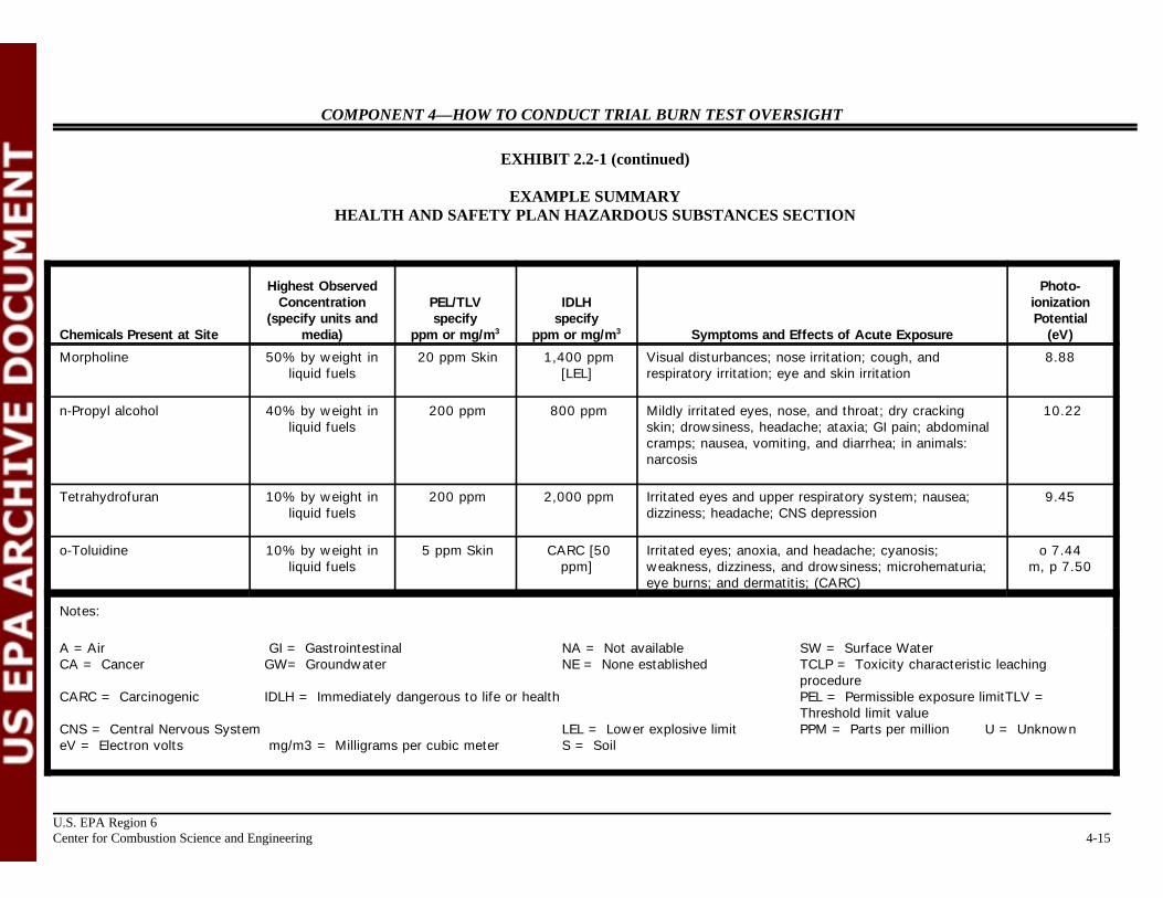
EXHIBIT 2.2-1 (continued)
EXAMPLE SUMMARYHEALTH AND SAFETY PLAN HAZARDOUS SUBSTANCES SECTION
U.S. EPA Region 6Center for Combustion Science and Engineering 4-14
Chemicals Present at Site media) ppm or mg/m ppm or mg/m Symptoms and Effects of Acute Exposure (eV)
Highest Observed Photo-Concentration PEL/TLV IDLH ionization
(specify units and specify specify Potential3 3
Acrylonitrile 5% by volume in 2 ppm CARC [85 ppm] Asphyxia; irritated eyes; headache; sneezing; nausea, 10.91gaseous fuels vomiting; weakness, light-headedness; skin vesiculation
and scaling dermatitis; (CARC)
Ammonia 5% by volume in 50 ppm 300 ppm Eye, nose, throat irritation; dyspnea; bronchospasm; 10.15gaseous fuels chest pain; pulmonary edema; pink, frothy sputum; skin
burns and vesiculation; liquid: frostbite
Butyl alcohol 40% by weight in 100 ppm 1,400 ppm Irritated eyes, nose, and throat; headache; vertigo; 10.04liquid fuels [LEL] drowsiness; corneal inflammation, blurred vision,
lacrimation, photophobia; dermatitis; possible auditorynerve damage, hearing loss; CNS depression
Diethylamine 10% by weight in 25 ppm 200 ppm Eye, skin, and respiratory irritation; in animals: 8.01liquid fuels myocardial degeneration
n-Ethylmorpholine 20% by weight in 20 ppm Skin 100 ppm Eyes, nose, and throat irritation; vision disturbances;liquid fuels corneal edema, blue-gray vision, and colored haloes
COMPONENT 4—HOW TO CONDUCT TRIAL BURN TEST OVERSIGHT
EXHIBIT 2.2-1 (continued)
EXAMPLE SUMMARYHEALTH AND SAFETY PLAN HAZARDOUS SUBSTANCES SECTION
Chemicals Present at Site media) ppm or mg/m ppm or mg/m Symptoms and Effects of Acute Exposure (eV)
Highest Observed Photo-Concentration PEL/TLV IDLH ionization
(specify units and specify specify Potential3 3
U.S. EPA Region 6Center for Combustion Science and Engineering 4-15
Morpholine 50% by weight in 20 ppm Skin 1,400 ppm Visual disturbances; nose irritation; cough, and 8.88liquid fuels [LEL] respiratory irritation; eye and skin irritation
n-Propyl alcohol 40% by weight in 200 ppm 800 ppm Mildly irritated eyes, nose, and throat; dry cracking 10.22liquid fuels skin; drowsiness, headache; ataxia; GI pain; abdominal
cramps; nausea, vomiting, and diarrhea; in animals:narcosis
Tetrahydrofuran 10% by weight in 200 ppm 2,000 ppm Irritated eyes and upper respiratory system; nausea; 9.45liquid fuels dizziness; headache; CNS depression
o-Toluidine 10% by weight in 5 ppm Skin CARC [50 Irritated eyes; anoxia, and headache; cyanosis; o 7.44liquid fuels ppm] weakness, dizziness, and drowsiness; microhematuria; m, p 7.50
eye burns; and dermatitis; (CARC)
Notes:
A =Air GI = Gastrointestinal NA = Not available SW = Surface WaterCA = Cancer GW= Groundwater NE = None established TCLP = Toxicity characteristic leaching
procedureCARC = Carcinogenic IDLH = Immediately dangerous to life or health PEL = Permissible exposure limitTLV =
Threshold limit valueCNS = Central Nervous System LEL = Lower explosive limit PPM = Parts per million U = UnknowneV = Electron volts mg/m3 = Milligrams per cubic meter S = Soil
COMPONENT 4—HOW TO CONDUCT TRIAL BURN TEST OVERSIGHT
U.S. EPA Region 6Center for Combustion Science and Engineering 4-16
U.S. EPA Region 6Center for Combustion Science and Engineering
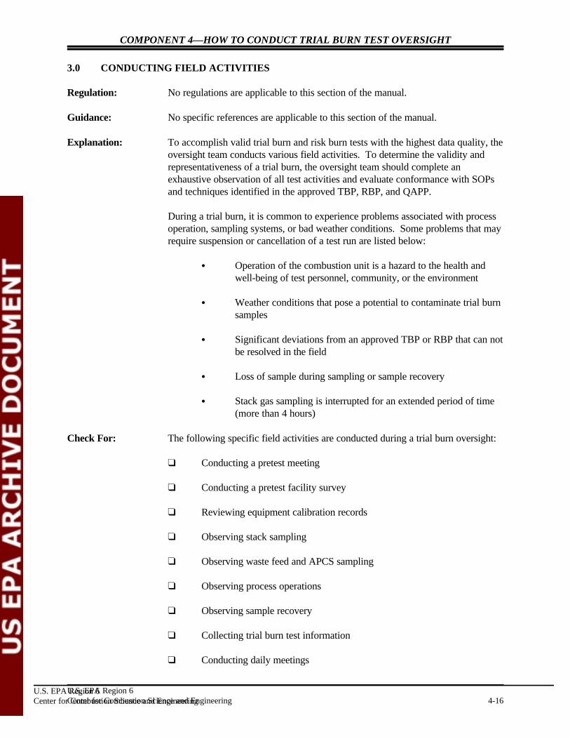
3.0 CONDUCTING FIELD ACTIVITIES
Regulation: No regulations are applicable to this section of the manual.
Guidance: No specific references are applicable to this section of the manual.
Explanation: To accomplish valid trial burn and risk burn tests with the highest data quality, theoversight team conducts various field activities. To determine the validity andrepresentativeness of a trial burn, the oversight team should complete anexhaustive observation of all test activities and evaluate conformance with SOPsand techniques identified in the approved TBP, RBP, and QAPP.
During a trial burn, it is common to experience problems associated with process operation, sampling systems, or bad weather conditions. Some problems that mayrequire suspension or cancellation of a test run are listed below:
C Operation of the combustion unit is a hazard to the health andwell-being of test personnel, community, or the environment
C Weather conditions that pose a potential to contaminate trial burnsamples
C Significant deviations from an approved TBP or RBP that can notbe resolved in the field
C Loss of sample during sampling or sample recovery
C Stack gas sampling is interrupted for an extended period of time(more than 4 hours)
Check For: The following specific field activities are conducted during a trial burn oversight:
“ Conducting a pretest meeting
“ Conducting a pretest facility survey
“ Reviewing equipment calibration records
“ Observing stack sampling
“ Observing waste feed and APCS sampling
“ Observing process operations
“ Observing sample recovery
“ Collecting trial burn test information
“ Conducting daily meetings
COMPONENT 4—HOW TO CONDUCT TRIAL BURN TEST OVERSIGHT
U.S. EPA Region 6Center for Combustion Science and Engineering 4-17
“ Compiling field documentation
“ Observing audit gas sampling
Sections 3.1 through 3.11 provide a detailed explanation of the above-listedactivities.
Example Section: Lois and Clark conduct a pretest meeting with all responsible personnel, includingthe facility trial burn, stack sampling, and QA/QC coordinators, and emphasizethe need for adhering to SOPs and procedures identified in the approved TBP,RBP, and QAPP. Lois and Clark briefly tour the facility to familiarize themselveswith process, sampling, and spiking areas. Lois observes the stack, waste feed,and APCS sampling. Clark observes process operating conditions and the samplerecovery. Lois and Clark record their observations in field logbooks and onobserver checklists. At the end of the day, Lois and Clark meet with allresponsible personnel, summarize their observations, provide recommendations,evaluate trial burn progress, and discuss test schedules for the following day.
Example Comments: During a trial burn, the oversight team should carry out their duties quietly andaccurately, conversing as little as practical with sampling and process controlpersonnel. Any deviations to or changes from procedures identified in theapproved TBP, RBP, and QAPP should be discussed directly and if appropriate,immediately with the facility trial burn coordinator. The oversight team shouldalso avoid touching any sampling or process equipment and assisting in anysampling or handling any sampling equipment during the trial burn.
Notes:

COMPONENT 4—HOW TO CONDUCT TRIAL BURN TEST OVERSIGHT
U.S. EPA Region 6Center for Combustion Science and Engineering 4-18
3.1 CONDUCTING A PRETEST MEETING
Regulation: No regulations are applicable to this section of the manual.
Guidance: No specific references are applicable to this section of the manual.
Explanation: For oversight to be conducted in a cohesive manner, a pretest meeting with thevarious agencies involved in the trial burn is necessary. All personnel involved inthe trial burn must understand that SOPs identified in the approved TBP and RBPmust be followed for the test to be successful..
Check For: “ Explain the role of the oversight team to trial burn personnel
“ Identify the individuals responsible for stack testing, waste feed sampling,APCS sampling, waste feed spiking, and recording process operating data
“ Determine the schedule and plan for trial burn testing
“ Identify any deviations from SOPs indicated in the TBP or RBP
Example Situation: In the pretest meeting, Lois and Clark explain that they will be observing (1) stackgas, waste feed, and scrubber effluent sampling, (2) waste feed spiking,(3) continuous emissions monitoring system (CEMS), and (4) general facilityoperating procedures. They will also record process operating data. Loisemphasizes that any deviations from or changes to SOPs in the approved TBP orRBP must be discussed and resolved with the oversight team. Lois and Clark alsostate that the calibration of all equipment involved in testing will be audited duringthe test.
Example Comments: Because the trial burn involves numerous activities occurring simultaneously, theoversight team should make prior arrangements with appropriate test personnel toobserve important activities, such as leak checks, sample recovery, sample fieldanalysis, and sample auditing. To the extent practicable, any problems that mayjeopardize the validity of the results should be resolved on site after appropriatepersonnel have been consulted.
Notes:
COMPONENT 4—HOW TO CONDUCT TRIAL BURN TEST OVERSIGHT
U.S. EPA Region 6Center for Combustion Science and Engineering 4-19
3.2 CONDUCTING A PRETEST FACILITY SURVEY
Regulations: No regulations are applicable to this section of the manual.
Guidance: No specific references are applicable to this section of the manual.
Explanation: Before the test begins, personnel should tour the facility, with the facility trial burncoordinator, to familiarize themselves with (1) the facility, (2) sampling locations,(3) procedures being followed, and (4) personnel associated with each specificactivity.
Check For: “ Examine the unit to be tested and observe general process operatingprocedures
“ Inspect the APCS associated with the unit to be tested and observe generaloperating procedures
“ Identify stack gas, waste feed, and APCS effluent sampling areas
“ Whether the stack includes a rain hat or an obstruction to gas flow
“ Sketch the stack gas sampling location
“ Examine the sampling platform or scaffold
“ Match the sampling trains with the appropriate sampling ports andbecome familiar with the order the trains will be employed
“ Inspect the stack gas sample recovery area and the field laboratory, if any
“ Determine the method and location of sample storage and labelingprocedures
“ Identify persons responsible for monitoring process operating conditionsand recording them at regular intervals
“ Identify stack sampling personnel and their individual responsibilities
“ Identify waste feed and APCS sampling personnel and their individual responsibilities

COMPONENT 4—HOW TO CONDUCT TRIAL BURN TEST OVERSIGHT
U.S. EPA Region 6Center for Combustion Science and Engineering 4-20
Temporary scaffolding is often used during stacksampling.
Example Situation: Lois and Clark briefly tour the combustion unit, generally observing the processoperations and ensuring that all monitoring equipment and sampling locations areacceptable, functional, and calibrated when necessary. Lois and Clark meet allpersonnel involved in the trial burn and identify their individual responsibilities.
Example Comments: The pretest field survey presents an opportunity to become familiar with the BIFunit and to meet key participants in the trial burn. It is recommended thatobservers make efforts to obtain answers for questions before the trial burnbegins. This minimizes interfering with test personnel during testing when theirattention should be focused on their individual responsibilities.
Notes:
COMPONENT 4—HOW TO CONDUCT TRIAL BURN TEST OVERSIGHT
U.S. EPA Region 6Center for Combustion Science and Engineering 4-21
3.3 REVIEWING EQUIPMENT CALIBRATION RECORDS
Regulation: No regulations are applicable to this section of the manual.
Guidance: No specific references are applicable to this section of the manual.
Explanation: Calibration of all process and sampling equipment is required to ensure thevalidity of data collected in the field. An audit of equipment calibration records isa critical component of trial burn or risk burn oversight. Obtain and reviewcalibration records of all items in the “Check For” section. It is acceptable torequest that the facility provide to the permit writer records of all completedcalibrations one to two weeks before testing begins. The remainder of allcalibration records should be available for review the day before testing begins.
Check For: “ Stack sampling equipment
“ Feed spiking equipment
“ Facility process control equipment
“ CEMS
“ Field laboratory instrumentation
These items are further explained in Subsections 3.3.1 through 3.3.5.
Example Situation: During the pretest briefing, Lois and Clark ask all organizations involved in thetrial burn to provide a list of calibration records identified in Subsections 3.3.1through 3.3.5 and a detailed description of maintenance procedures.

COMPONENT 4—HOW TO CONDUCT TRIAL BURN TEST OVERSIGHT
U.S. EPA Region 6Center for Combustion Science and Engineering 4-22
This combination mass flow meter/controller/transmitter is often used to regulate, measure,and monitor the mass flow rate of hazardouswaste fuel. Calibration records should beobtained for all flow meters.
Example Action: Stack sampling equipment are usually calibrated before stack testing and after testing completion. Lois and Clark ask ABC Environmental to providepost-calibration records of all sampling equipment at the end of testing. Comparing pretest and post-test calibration records provides importantinformation on the quality of the field data collected.
Notes:
COMPONENT 4—HOW TO CONDUCT TRIAL BURN TEST OVERSIGHT
U.S. EPA Region 6Center for Combustion Science and Engineering 4-23
3.3.1 Reviewing Stack Sampling Equipment Calibration Records
Regulation: No regulations are applicable to this section of the manual.
Guidance: No specific references are applicable to this section of the manual.
Explanation: Obtain calibration records of stack sampling equipment identified in the followingchecklist.
Check For: “ Pitot tubes
“ Differential pressure gauges
“ Temperature indicators
“ Dry gas meters
“ Probe nozzles
“ Rotameters
“ Barometer
Example Section: A blank digital temperature indicator calibration form is included as Exhibit 3.3.1-1, see page 4-25.
Example Comments: Manufacturers of most stack sampling equipment provide specifictroubleshooting, calibration, and maintenance procedures. If records provided bythe stack sampling company are inadequate, the oversight team should requestthen review the manufacturer-supplied literature for calibration and maintenanceprocedures.
Notes:

COMPONENT 4—HOW TO CONDUCT TRIAL BURN TEST OVERSIGHT
U.S. EPA Region 6Center for Combustion Science and Engineering 4-24
This rotameter arrangement is often used inconjunction with the Method 0040 sampling trainto monitor vacuum flow rate. Oversightpersonnel should ensure that flow remainsconstant by periodically checking the level of therotameter during the trial burn test.

COMPONENT 4—HOW TO CONDUCT TRIAL BURN TEST OVERSIGHT
U.S. EPA Region 6Center for Combustion Science and Engineering 4-25
EXHIBIT 3.3.1-1
BLANK DIGITAL TEMPERATURE INDICATOR CALIBRATION FORM
DIGITAL TEMPERATURE INDICATOR NO. CALIBRATION DATA
Date:
Medium Time Mercury Temperature DTI (EEF)
Ambient air
Ice bath
Boiling water
Oven
Oven
Oven
Oven
Note: DTI = Digital Temperature Indicator
Meter Adjusted? Yes No
Signature of Calibrator
COMPONENT 4—HOW TO CONDUCT TRIAL BURN TEST OVERSIGHT
U.S. EPA Region 6Center for Combustion Science and Engineering 4-26
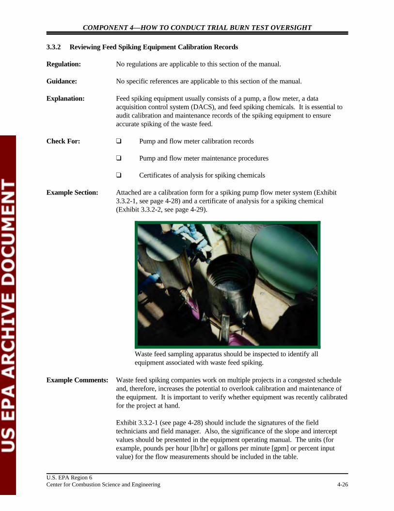
Waste feed sampling apparatus should be inspected to identify allequipment associated with waste feed spiking.
3.3.2 Reviewing Feed Spiking Equipment Calibration Records
Regulation: No regulations are applicable to this section of the manual.
Guidance: No specific references are applicable to this section of the manual.
Explanation: Feed spiking equipment usually consists of a pump, a flow meter, a dataacquisition control system (DACS), and feed spiking chemicals. It is essential toaudit calibration and maintenance records of the spiking equipment to ensureaccurate spiking of the waste feed.
Check For: “ Pump and flow meter calibration records
“ Pump and flow meter maintenance procedures
“ Certificates of analysis for spiking chemicals
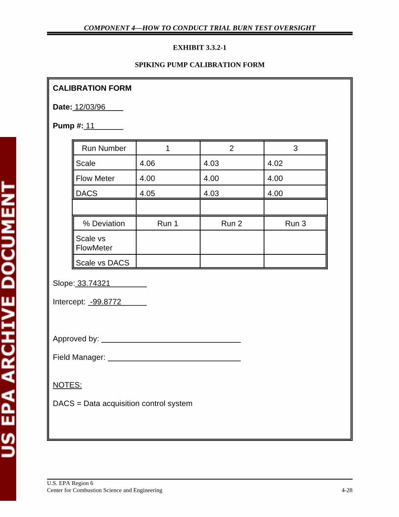
Example Section: Attached are a calibration form for a spiking pump flow meter system (Exhibit3.3.2-1, see page 4-28) and a certificate of analysis for a spiking chemical(Exhibit 3.3.2-2, see page 4-29).
Example Comments: Waste feed spiking companies work on multiple projects in a congested scheduleand, therefore, increases the potential to overlook calibration and maintenance ofthe equipment. It is important to verify whether equipment was recently calibratedfor the project at hand.
Exhibit 3.3.2-1 (see page 4-28) should include the signatures of the fieldtechnicians and field manager. Also, the significance of the slope and interceptvalues should be presented in the equipment operating manual. The units (forexample, pounds per hour [lb/hr] or gallons per minute [gpm] or percent inputvalue) for the flow measurements should be included in the table.
COMPONENT 4—HOW TO CONDUCT TRIAL BURN TEST OVERSIGHT
U.S. EPA Region 6Center for Combustion Science and Engineering 4-27
Notes:
COMPONENT 4—HOW TO CONDUCT TRIAL BURN TEST OVERSIGHT
U.S. EPA Region 6Center for Combustion Science and Engineering 4-28
EXHIBIT 3.3.2-1
SPIKING PUMP CALIBRATION FORM
CALIBRATION FORM
Date: 12/03/96
Pump #: 11
Run Number 1 2 3
Scale 4.06 4.03 4.02
Flow Meter 4.00 4.00 4.00
DACS 4.05 4.03 4.00
% Deviation Run 1 Run 2 Run 3
Scale vsFlowMeter
Scale vs DACS
Slope: 33.74321
Intercept: -99.8772
Approved by:
Field Manager:
NOTES:
DACS = Data acquisition control system

COMPONENT 4—HOW TO CONDUCT TRIAL BURN TEST OVERSIGHT
U.S. EPA Region 6Center for Combustion Science and Engineering 4-29
CERTIFICATE OF ANALYSIS
Customer: ABC CompanySomewhere, USA
Product: AMSPERSE ENV 280-1Sodium Dichromate Solution
Batch #: 4458 P.O. #: B3-97012.01
RESULTS OF ANALYSIS
Chromium, CR+6 0.4%
______________________
Amount, lbs. 900#
ISSUED BY: Ann AlysisLab Tech
EXHIBIT 3.3.2-2
SPIKING CHEMICAL CERTIFICATE OF ANALYSIS

COMPONENT 4—HOW TO CONDUCT TRIAL BURN TEST OVERSIGHT
U.S. EPA Region 6Center for Combustion Science and Engineering 4-30
Local control panels often include meters and local data readoutsthat should also have calibration records.
3.3.3 Reviewing Process Control Equipment Calibration Records
Regulation: No regulations are applicable to this section of the manual.
Guidance: No specific references are applicable to this section of the manual.
Explanation: The operation of a combustion unit is usually controlled by numerous pieces ofprocess control equipment. To ensure that data collected during a trial burn areprecise and accurate, the oversight team should audit calibration and maintenancerecords of all relevant process control equipment before the start of testing. Verifycalibration and maintenance records of the items in the following check list:
Check For: “ Waste feed flow meters
“ Atomization air pressure transmitters
“ Pyrometers
“ Differential pressure gauges across APCSs
“ pH meters
“ Oxidation and reduction potential meters
“ Integral orifice meters
“ Thermocouples and temperature indicators

COMPONENT 4—HOW TO CONDUCT TRIAL BURN TEST OVERSIGHT
U.S. EPA Region 6Center for Combustion Science and Engineering 4-31
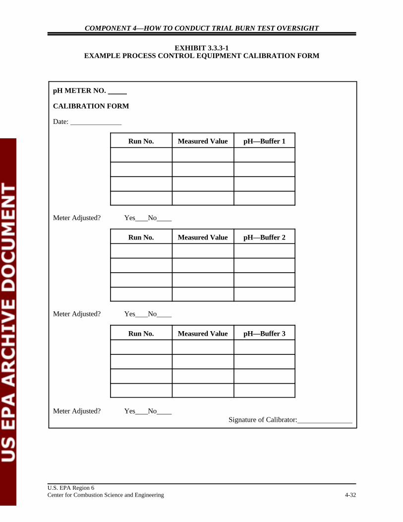
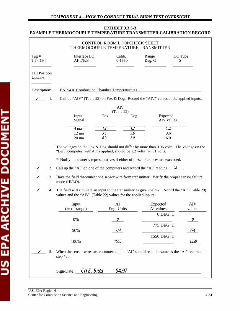
Example Section: Attached are a blank calibration form for a pH meter (Exhibit 3.3.3-1, see page 4-32) and a calibration report for an infrared thermometer (Exhibit 3.3.3-2, see page4-33).
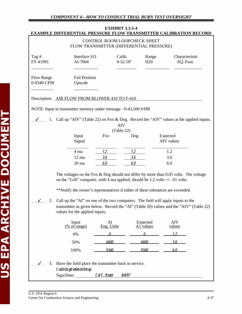
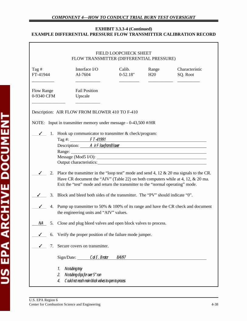
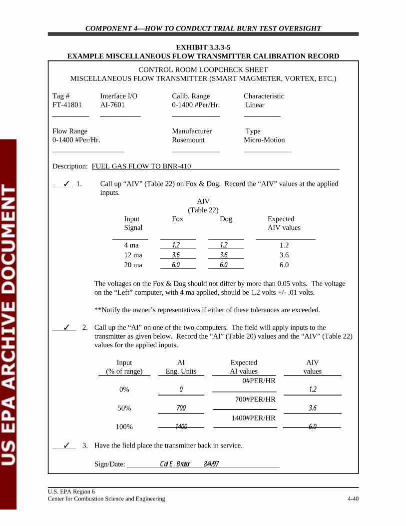
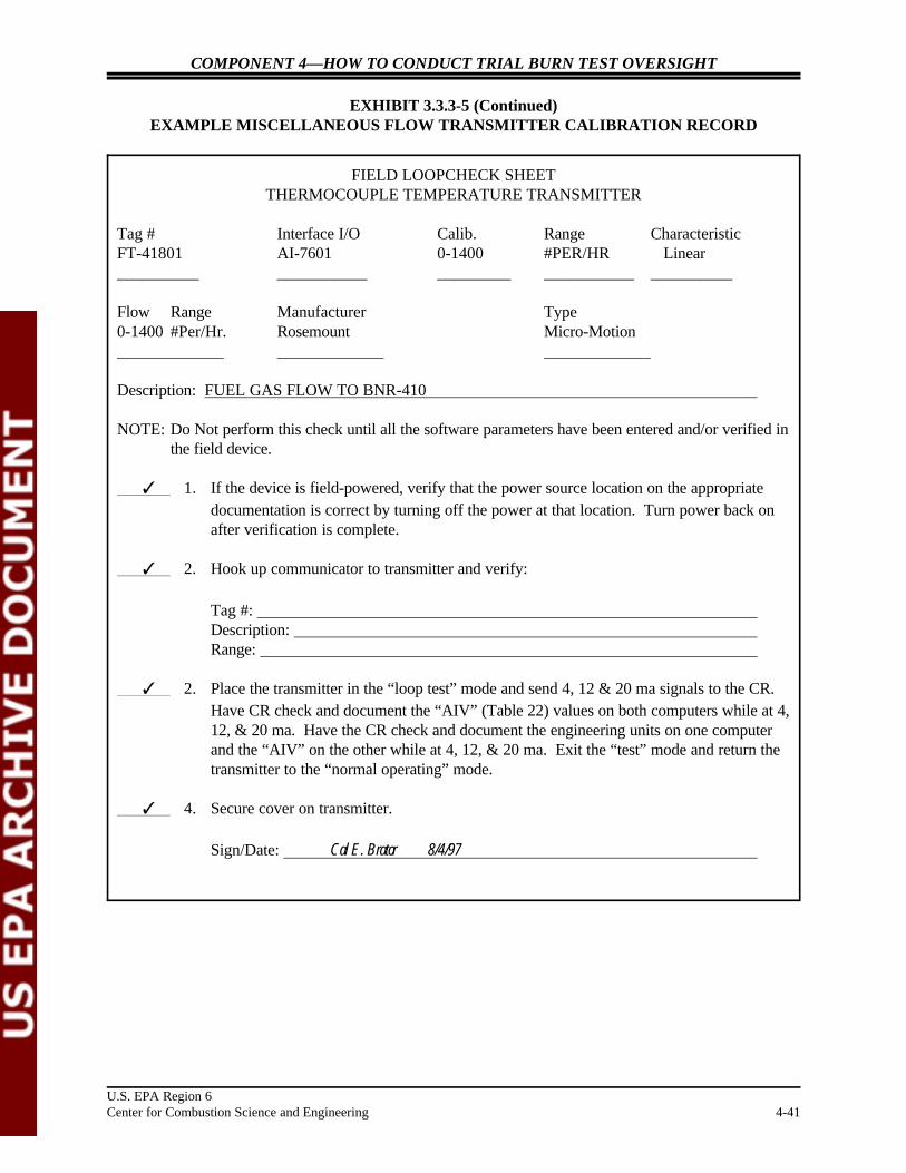
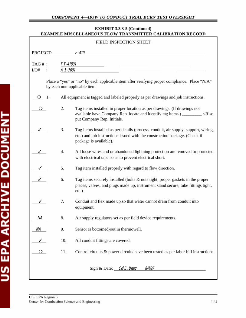
Also attached are completed control room and field loopcheck and inspectionsheets: Exhibits 3.3.3-3 (see page 4-34), 3.3.3-4 (see page 4-37), and 3.3.3-5 (seepage 4-40).
Example Comments: Instruments should be calibrated at multiple measurement points evenly spacedover a range. When practical, at least one calibration point should approximatelevels anticipated in the actual test measurement.
Exhibit 3.3.3-1 (see page 4-32) should include the date of calibration. It is alsohelpful to include the instrument tag number or model number to be more specificthan simply meter number. In addition, a description of the instrument’s location,for example pH meter in acid gas scrubber number 1, would aid in understandinghow and where the instrument is used.
Almost all of the values recorded on the Exhibits 3.3.3-3 (see page 4-34), through3.3.3-5 (see page 4-40), calibration sheets reflect acceptable expected values. These values indicate that the instrument is operating within recommended limits. It is helpful to review the instrument operating manuals to better understand thecalibration procedures.
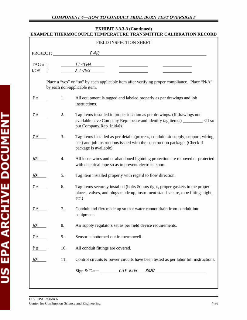
As seen on Exhibit 3.3.3-5, see page 4-42, Field Inspection Sheet, items 1, 2, and3 are circled and unanswered. The significance of these omissions is unclear. Thefacility should explain the situation surrounding these omissions and determinewhether the calibration results are suspect.
Notes:
COMPONENT 4—HOW TO CONDUCT TRIAL BURN TEST OVERSIGHT
U.S. EPA Region 6Center for Combustion Science and Engineering 4-32
pH METER NO.
CALIBRATION FORM
Date:
Run No. Measured Value pH—Buffer 1
Meter Adjusted? Yes No
Run No. Measured Value pH—Buffer 2
Meter Adjusted? Yes No
Run No. Measured Value pH—Buffer 3
Meter Adjusted? Yes NoSignature of Calibrator:
EXHIBIT 3.3.3-1EXAMPLE PROCESS CONTROL EQUIPMENT CALIBRATION FORM

COMPONENT 4—HOW TO CONDUCT TRIAL BURN TEST OVERSIGHT
U.S. EPA Region 6Center for Combustion Science and Engineering 4-33
CERTIFICATE OF CALIBRATIONFOR
INFRARED THERMOMETER
Model MR-OR05-32F-1-1/0-0-0 Test Report No. RD-106965Serial No. 26009 Date February 5, 1997
INDICATED TEMPERATURE VS BLACKBODY STANDARD TEMPERATURE
BlackbodyTemperature
T (EEF or EEC)TRUE
IndicatedTemperature
T (EEF or EEC)IND
Correction FactorÎÎT (EEF or EEC)CORR
Thermometer Output(If Applicable)
1800EF 1800EF 0EF NA
2100EF 2098EF 2EF NA
2400EF 2398EF 2EF NA
2800EF 2799EF 1EF NA
3200EF 3200EF 0EF NA
EF EF EF NA
NOTES: Indicated Temperature (T ) is temperature displayed on built-in meter of thermometer.IND
T = T 1ÎTTRUE IND CORR
EXHIBIT 3.3.3-2INFRARED THERMOMETER CALIBRATION REPORT
COMPONENT 4—HOW TO CONDUCT TRIAL BURN TEST OVERSIGHT
U.S. EPA Region 6Center for Combustion Science and Engineering 4-34
CONTROL ROOM LOOPCHECK SHEETTHERMOCOUPLE TEMPERATURE TRANSMITTER
Tag # Interface I/O Calib. Range T/C TypeTT-41944 AI-I7623 0-1550 Deg. C S__________ ___________ _________ ___________ __________
Fail PositionUpscale __________
Description: BNR-410 Combustion Chamber Temperature #1
T 1. Call up “AIV” (Table 22) on Fox & Dog. Record the “AIV” values at the applied inputs.
AIV(Table 22)
Input Fox Dog ExpectedSignal AIV values
4 ma 1.2 1.2 1.212 ma 3.6 3.6 3.620 ma 6.0 6.0 6.0
The voltages on the Fox & Dog should not differ by more than 0.05 volts. The voltage on the“Left” computer, with 4 ma applied, should be 1.2 volts +/- .01 volts.
**Notify the owner’s representatives if either of these tolerances are exceeded.
T 2. Call up the “AI” on one of the computers and record the “AI” reading 28 .
T 3. Have the field disconnect one sensor wire from transmitter. Verify the proper sensor failuremode (HI/LO).
T 4. The field will simulate an input to the transmitter as given below. Record the “AI” (Table 20)values and the “AIV” (Table 22) values for the applied inputs.
Input(% of range)
AIEng. Units
ExpectedAI values
AIVvalues
0 DEG. C0% 0 ______________ 0
775 DEG. C50% 774 ______________ 774
1550 DEG. C100% 1550 ______________ 1550
T 5. When the sensor wires are reconnected, the “AI” should read the same as the “AI” recorded instep #2.
Sign/Date: Cal E. Brator 8/4/97
EXHIBIT 3.3.3-3EXAMPLE THERMOCOUPLE TEMPERATURE TRANSMITTER CALIBRATION RECORD

COMPONENT 4—HOW TO CONDUCT TRIAL BURN TEST OVERSIGHT
U.S. EPA Region 6Center for Combustion Science and Engineering 4-35
FIELD LOOPCHECK SHEETTHERMOCOUPLE TEMPERATURE TRANSMITTER
Tag # Interface I/O Calib. Range T/C TypeTT-41944 AI-I7623 0-1550 Deg. C S__________ ___________ _________ ___________ __________
Fail PositionUpscale __________
Description: BNR-410 Combustion Chamber Temperature #1
T 1. Hook up communicator to transmitter & check/program:Tag #: Description: Range: Message (Mod5 I/O): Sensor type:
T 2. Place the transmitter in the “loop test” mode and send 4, 12 & 20 ma signals to the CR. Have CR document the “AIV” (Table 22) on both computers while at 4, 12, & 20 ma. Exit the “test” mode and return the transmitter to the “normal operating” mode.
T 3. Call up the “PV” on the communicator. The “PV” should indicate the current processtemperature and should agree with the CR. Record the “PV”: 30.6.
T 4. Disconnect one sensor wire from the transmitter. The transmitter should go into itssensor failure mode. Verify with the CR. If the transmitter fails in the wrong direction,move the failure mode jumper to the correct position. Disconnect the other sensor wirefrom the transmitter.
T 5. Hook up a T/C temperature simulator to the transmitter. Simulate 0, 50, & 100% of itsrange. Have the CR check and document the engineering units and “AIV” values.
T 6. Reconnect the sensor wires to transmitter. Verify indication is the same as recorded instep #3.
T 7. Secure cover on transmitter.
Sign/Date: Cal E. Brator 8/4/97
EXHIBIT 3.3.3-3 (Continued)EXAMPLE THERMOCOUPLE TEMPERATURE TRANSMITTER CALIBRATION RECORD
COMPONENT 4—HOW TO CONDUCT TRIAL BURN TEST OVERSIGHT
U.S. EPA Region 6Center for Combustion Science and Engineering 4-36
FIELD INSPECTION SHEET
PROJECT: F-410
TAG # : TT-41944I/O# : AI-7623
Place a “yes” or “no” by each applicable item after verifying proper compliance. Place “N/A”by each non-applicable item.
Yes 1. All equipment is tagged and labeled properly as per drawings and jobinstructions.
Yes 2. Tag items installed in proper location as per drawings. (If drawings notavailable have Company Rep. locate and identify tag items.) _________ <If soput Company Rep. Initials.
Yes 3. Tag items installed as per details (process, conduit, air supply, support, wiring,etc.) and job instructions issued with the construction package. (Check ifpackage is available).
NA 4. All loose wires and or abandoned lightning protection are removed or protectedwith electrical tape so as to prevent electrical short.
NA 5. Tag item installed properly with regard to flow direction.
Yes 6. Tag items securely installed (bolts & nuts tight, proper gaskets in the properplaces, valves, and plugs made up, instrument stand secure, tube fittings tight,etc.)
Yes 7. Conduit and flex made up so that water cannot drain from conduit intoequipment.
NA 8. Air supply regulators set as per field device requirements.
Yes 9. Sensor is bottomed-out in thermowell.
Yes 10. All conduit fittings are covered.
NA 11. Control circuits & power circuits have been tested as per labor bill instructions.
Sign & Date: Cal E. Brator 8/4/97
EXHIBIT 3.3.3-3 (Continued)EXAMPLE THERMOCOUPLE TEMPERATURE TRANSMITTER CALIBRATION RECORD
COMPONENT 4—HOW TO CONDUCT TRIAL BURN TEST OVERSIGHT
U.S. EPA Region 6Center for Combustion Science and Engineering 4-37
CONTROL ROOM LOOPCHECK SHEETFLOW TRANSMITTER (DIFFERENTIAL PRESSURE)
Tag # Interface I/O Calib. Range Characteristic FT-41991 AI-7604 0-52.18" H20 SQ. Foot__________ ___________ _________ ___________ _____________
Flow Range Fail Position0-9340 CFM Upscale __________ ___________
Description: AIR FLOW FROM BLOWER 410 TO F-410
NOTE: Input in transmitter memory under message - 0-43,500 #/HR
T 1. Call up “AIV” (Table 22) on Fox & Dog. Record the “AIV” values at the applied inputs.AIV
(Table 22)Input Fox Dog ExpectedSignal AIV values
4 ma 1.2 1.2 1.212 ma 3.6 3.6 3.620 ma 6.0 6.0 6.0
The voltages on the Fox & Dog should not differ by more than 0.05 volts. The voltageon the “Left” computer, with 4 ma applied, should be 1.2 volts +/- .01 volts.
**Notify the owner’s representatives if either of these tolerances are exceeded.
T 2. Call up the “AI” on one of the two computers. The field will apply inputs to thetransmitter as given below. Record the “AI” (Table 20) values and the “AIV” (Table 22)values for the applied inputs.
Input AI Expected AIV(% of range) Eng. Units A1 values values
0% 0 0 1.2
50% 6600 6600 3.6
100% 9340 9340 6.0
T 3. Have the field place the transmitter back in service.Could not get valves to line up.Sign/Date: Cal E. Brator 8/4/97
EXHIBIT 3.3.3-4EXAMPLE DIFFERENTIAL PRESSURE FLOW TRANSMITTER CALIBRATION RECORD
COMPONENT 4—HOW TO CONDUCT TRIAL BURN TEST OVERSIGHT
U.S. EPA Region 6Center for Combustion Science and Engineering 4-38
FIELD LOOPCHECK SHEETFLOW TRANSMITTER (DIFFERENTIAL PRESSURE)
Tag # Interface I/O Calib. Range CharacteristicFT-41944 AI-7604 0-52.18" H20 SQ. Root__________ ___________ _________ ___________ __________
Flow Range Fail Position0-9340 CFM Upscale_______________ ___________
Description: AIR FLOW FROM BLOWER 410 TO F-410
NOTE: Input in transmitter memory under message - 0-43,500 #/HR
T 1. Hook up communicator to transmitter & check/program:Tag #: FT-41991Description: Air Flow from BlowerRange: Message (Mod5 I/O): Output characteristics:
T 2. Place the transmitter in the “loop test” mode and send 4, 12 & 20 ma signals to the CR. Have CR document the “AIV” (Table 22) on both computers while at 4, 12, & 20 ma. Exit the “test” mode and return the transmitter to the “normal operating” mode.
T 3. Block and bleed both sides of the transmitter. The “PV” should indicate “0".
T 4. Pump up transmitter to 50% & 100% of its range and have the CR check and documentthe engineering units and “AIV” values.
NA 5. Close and plug bleed valves and open block valves to process.
T 6. Verify the proper position of the failure mode jumper.
T 7. Secure covers on transmitter.
Sign/Date: Cal E. Brator 8/4/97
1. No tubing tray 2. No tubing clips for over 5" run
4. Could not reach main block valves to open to process
EXHIBIT 3.3.3-4 (Continued)EXAMPLE DIFFERENTIAL PRESSURE FLOW TRANSMITTER CALIBRATION RECORD

COMPONENT 4—HOW TO CONDUCT TRIAL BURN TEST OVERSIGHT
U.S. EPA Region 6Center for Combustion Science and Engineering 4-39
FIELD INSPECTION SHEET
PROJECT: F-410
TAG # : FT-41991I/O# : AI-7604
Place a “yes” or “no” by each applicable item after verifying proper compliance. Place “N/A”by each non-applicable item.
T 1. All equipment is tagged and labeled properly as per drawings and jobinstructions.
T 2. Tag items installed in proper location as per drawings. (If drawings notavailable have Company Rep. locate and identify tag items.) _________ <If soput Company Rep. Initials.
T 3. Tag items installed as per details (process, conduit, air supply, support, wiring,etc.) and job instructions issued with the construction package. (Check ifpackage is available).
T 4. All loose wires and or abandoned lightning protection are removed or protectedwith electrical tape so as to prevent electrical short.
T 5. Tag item installed properly with regard to flow direction.
6. Tag items securely installed (bolts & nuts tight, proper gaskets in the properplaces, valves, and plugs made up, instrument stand secure, tube fittings tight,etc.)
7. Conduit and flex made up so that water cannot drain from conduit intoequipment.
NA 8. Air supply regulators set as per field device requirements.
NA 9. Sensor is bottomed-out in thermowell.
T 10. All conduit fittings are covered.
11. Control circuits & power circuits have been tested as per labor bill instructions.
Sign & Date: Cal E. Brator 8/4/97
EXHIBIT 3.3.3-4 (Continued)EXAMPLE DIFFERENTIAL PRESSURE FLOW TRANSMITTER CALIBRATION RECORD
COMPONENT 4—HOW TO CONDUCT TRIAL BURN TEST OVERSIGHT
U.S. EPA Region 6Center for Combustion Science and Engineering 4-40
CONTROL ROOM LOOPCHECK SHEETMISCELLANEOUS FLOW TRANSMITTER (SMART MAGMETER, VORTEX, ETC.)
Tag # Interface I/O Calib. Range CharacteristicFT-41801 AI-7601 0-1400 #Per/Hr. Linear__________ ___________ _____________ __________
Flow Range Manufacturer Type0-1400 #Per/Hr. Rosemount Micro-Motion
Description: FUEL GAS FLOW TO BNR-410
T 1. Call up “AIV” (Table 22) on Fox & Dog. Record the “AIV” values at the appliedinputs.
AIV(Table 22)
Input Fox Dog ExpectedSignal AIV values
4 ma 1.2 1.2 1.212 ma 3.6 3.6 3.620 ma 6.0 6.0 6.0
The voltages on the Fox & Dog should not differ by more than 0.05 volts. The voltageon the “Left” computer, with 4 ma applied, should be 1.2 volts +/- .01 volts.
**Notify the owner’s representatives if either of these tolerances are exceeded.
T 2. Call up the “AI” on one of the two computers. The field will apply inputs to thetransmitter as given below. Record the “AI” (Table 20) values and the “AIV” (Table 22)values for the applied inputs.
Input(% of range)
AIEng. Units
ExpectedAI values
AIVvalues
0#PER/HR0% 0 1.2
700#PER/HR50% 700 3.6
1400#PER/HR100% 1400 6.0
T 3. Have the field place the transmitter back in service.
Sign/Date: Cal E. Brator 8/4/97
EXHIBIT 3.3.3-5EXAMPLE MISCELLANEOUS FLOW TRANSMITTER CALIBRATION RECORD
COMPONENT 4—HOW TO CONDUCT TRIAL BURN TEST OVERSIGHT
U.S. EPA Region 6Center for Combustion Science and Engineering 4-41
FIELD LOOPCHECK SHEETTHERMOCOUPLE TEMPERATURE TRANSMITTER
Tag # Interface I/O Calib. Range CharacteristicFT-41801 AI-7601 0-1400 #PER/HR Linear__________ ___________ _________ ___________ __________
Flow Range Manufacturer Type0-1400 #Per/Hr. Rosemount Micro-Motion
Description: FUEL GAS FLOW TO BNR-410
NOTE: Do Not perform this check until all the software parameters have been entered and/or verified inthe field device.
T 1. If the device is field-powered, verify that the power source location on the appropriatedocumentation is correct by turning off the power at that location. Turn power back onafter verification is complete.
T 2. Hook up communicator to transmitter and verify:
Tag #: Description: Range:
T 2. Place the transmitter in the “loop test” mode and send 4, 12 & 20 ma signals to the CR. Have CR check and document the “AIV” (Table 22) values on both computers while at 4,12, & 20 ma. Have the CR check and document the engineering units on one computerand the “AIV” on the other while at 4, 12, & 20 ma. Exit the “test” mode and return thetransmitter to the “normal operating” mode.
T 4. Secure cover on transmitter.
Sign/Date: Cal E. Brator 8/4/97
EXHIBIT 3.3.3-5 (Continued)EXAMPLE MISCELLANEOUS FLOW TRANSMITTER CALIBRATION RECORD
COMPONENT 4—HOW TO CONDUCT TRIAL BURN TEST OVERSIGHT
U.S. EPA Region 6Center for Combustion Science and Engineering 4-42
FIELD INSPECTION SHEET
PROJECT: F-410
TAG # : FT-41801I/O# : AI-7601
Place a “yes” or “no” by each applicable item after verifying proper compliance. Place “N/A”by each non-applicable item.
� 1. All equipment is tagged and labeled properly as per drawings and job instructions.
� 2. Tag items installed in proper location as per drawings. (If drawings notavailable have Company Rep. locate and identify tag items.) _________ <If soput Company Rep. Initials.
T 3. Tag items installed as per details (process, conduit, air supply, support, wiring,etc.) and job instructions issued with the construction package. (Check ifpackage is available).
T 4. All loose wires and or abandoned lightning protection are removed or protectedwith electrical tape so as to prevent electrical short.
T 5. Tag item installed properly with regard to flow direction.
T 6. Tag items securely installed (bolts & nuts tight, proper gaskets in the properplaces, valves, and plugs made up, instrument stand secure, tube fittings tight,etc.)
T 7. Conduit and flex made up so that water cannot drain from conduit intoequipment.
NA 8. Air supply regulators set as per field device requirements.
NA 9. Sensor is bottomed-out in thermowell.
T 10. All conduit fittings are covered.
� 11. Control circuits & power circuits have been tested as per labor bill instructions.
Sign & Date: Cal E. Brator 8/4/97
EXHIBIT 3.3.3-5 (Continued)EXAMPLE MISCELLANEOUS FLOW TRANSMITTER CALIBRATION RECORD

COMPONENT 4—HOW TO CONDUCT TRIAL BURN TEST OVERSIGHT
U.S. EPA Region 6Center for Combustion Science and Engineering 4-43
3.3.4 Reviewing Continuous Emission Monitoring System Calibration Records
Regulation: No regulations are applicable to this section of the manual.
Guidance: No specific references are applicable to this section of the manual.
Explanation: CEMS do not operate accurately and reliably without well-planned and frequentmaintenance. To ensure that data collected during a trial burn are of high quality,the maintenance oversight team should audit the certification and calibrationrecords of all CEMS.
Check For: “ Latest CEMS certification report
“ Automatic daily calibration records
“ Periodic manual calibration records
“ Certificates of analysis of calibration gases
Example Section: Performance specifications of CEMS are defined below. In addition, a samplemultipoint CEMS calibration data sheet (Exhibit 3.3.4-1, see page 4-45) andexamples of performance specification test results (Exhibit 3.3.4-2, see page 4-46)and relative accuracy test results (Exhibit 3.3.4-3, see page 4-47), are alsoattached.
• Calibration Drift—difference in the CEMS output reading fromthe established reference value after a stated period of operationduring which no unscheduled maintenance, repair, or adjustmenttook place
• Calibration Error—difference between the concentration indicatedby the CEMS and the known concentration of the cylinder gas
• Relative Accuracy—a comparison of the CEMS response to avalue measured by a reference method (that is, Method 3, 3a, 10,10A, or 10B) described in 40 CFR Part 60.
• Response Time—time interval between the start of a step changein system input and the time when recorder displays 95 percent ofthe input value.

COMPONENT 4—HOW TO CONDUCT TRIAL BURN TEST OVERSIGHT
U.S. EPA Region 6Center for Combustion Science and Engineering 4-44
Calibration records should be collected for allCEMS, including units such as this carbonmonoxide and oxygen monitoring system.
Example Comments: CEMS calibration should not drift or deviate from the reference value of thereference gas cylinder, gas cell, or optical filter by more than 2.5 percent of thespan value. Relative accuracy of the CEMS should be no greater than 20 percentof the mean value of the reference method test data in terms of units of theemission standard or 10 percent of the applicable standard, whichever is greater. The response time for CO and O2 monitors should not exceed 2 minutes.
Notes:

COMPONENT 4—HOW TO CONDUCT TRIAL BURN TEST OVERSIGHT
U.S. EPA Region 6Center for Combustion Science and Engineering 4-45
EXHIBIT 3.3.4-1
EXAMPLE CEMS MULTIPOINT CALIBRATION DATA SHEET
Ana
lyze
r Res
pons
e (P
PM)
ParameterSite Engineer Date (hour)
Instrument model Instrument S/N Instrument range
Standards
Unadjusted: Recalibrate if Response GreaterThan ±10 Percent
Input Concentration (ppm)
Input Response %Difference RF(Input÷Response)
Overall MeanRF
Adjusted: Adjust Analyzer Response at 40 Percent of Full Scale
Comments RF is response factor. The instrument linearity is acceptable if the RF at each point is within2.5 percent of overall mean RF. A linearity check calibration is completed before the system is firstplaced into operation.

COMPONENT 4—HOW TO CONDUCT TRIAL BURN TEST OVERSIGHT
U.S. EPA Region 6Center for Combustion Science and Engineering 4-46
EXHIBIT 3.3.4-2
EXAMPLE PERFORMANCE SPECIFICATION TEST RESULTS
SUMMARY OF RESULTS
RELATIVE ACCURACY, CALIBRATION DRIFT, CALIBRATION ERROR AND RESPONSE TIMES
Parameter System
RelativeAccuracy
Maximum CalibrationDrift Calibration Error
ResponseTime
Allowable
Low LevelHighLevel Low Level Mid Level
HighLevel
RelativeAccuracy
Calibration Drift
CalibrationError
ResponseTime
CarbonMonoxide
1 5.33% 1 ppm 8 ppm 0.47 ppm 0.67 ppm 2.33 ppm 1.42 min 10.0% or10 ppm
# 15 ppm # 25 ppm # 2 min.
Oxygen 1 3.27% 0.1% 02 0.4% 02 0.04% 02 0.11% 02 0.08% 02 1.48 min. # 20% # 0.5% 02 0.5% 02 # 2 min.
CarbonMonoxide
2 1.44% 1 ppm 8 ppm 0.87 ppm 2.00 ppm 8.33 ppm 1.22 min. 10.0% or10 ppm
# 16 ppm # 25 ppm # 2 min.
Oxygen 2 3.12% 0.2% 02 0.4% 02 0.05% 02 0.19% 02 0.27% 02 1.29 min. # 20% # 0.5% 02 0.5% 02 # 2 min.
COMMENTS: A calibration drift test is completed to demonstrate the stability of CEMS calibration over a period of time. A calibration error test isconducted to document the accuracy and linearity of CEMS over the entire measurement range. A risk assessment test is conducted to verify therepresentativeness and accuracy of CEMS measurements.

COMPONENT 4—HOW TO CONDUCT TRIAL BURN TEST OVERSIGHT
U.S. EPA Region 6Center for Combustion Science and Engineering 4-47
EXHIBIT 3.3.4-3
EXAMPLE RELATIVE ACCURACY TEST RESULTS
SUMMARY OF RESULTS
Carbon Monoxide Monitor Certification
Run Number Date Time
ReferenceMethodppm CO
MonitorReadingppm CO
Differenceppm CO
1 08/01/96 0854-0915 66.3 63.41 -2.89
2 08/01/96 0927-0948 61.5 58.64 -2.86
3 08/01/96 0959-1020 65.0 62.22 -2.78
4 08/01/96 1030-1051 42.3 39.71 -2.59
5 08/01/96 1134-1155 57.6 54.57 -3.03
6 08/01/96 1206-1227 56.0 52.89 -3.11
7 08/01/96 1238-1259 56.9 54.04 -2.86
8 08/01/96 1311-1332 57.0 54.06 -2.94
9 08/01/96 1343-1404 41.9 39.33 -2.57
Average 56.06 53.21 -2.85
Standard Deviation = 0.18 ppm CO
Confidence Coefficient = 0.14 ppm CO
I Mean Difference I + Confidence Coefficient = 2.99 ppm CO
Relative Accuracy = I Mean Difference I + Confidence Coefficient x 100 = 5.39%Average Reference Method

COMPONENT 4—HOW TO CONDUCT TRIAL BURN TEST OVERSIGHT
U.S. EPA Region 6Center for Combustion Science and Engineering 4-48
3.3.5 Reviewing Field Laboratory Instrumentation Calibration Records
Regulation: No regulations are applicable to this section of the manual.
Guidance: No specific references are applicable to this section of the manual.
Explanation: A field laboratory usually consists of numerous analytical reagents, analyticalbalances, certified gases, and field GC/FID. Component 5 contains detailedchecklists and an explanation of a laboratory audit. While Component 5 focuseson off-site laboratories, many of the audit techniques can be used for fieldlaboratories as well.
Check For: “ Certificates of analysis
“ Calibration records
“ Maintenance procedures
Example Section: Please refer to Component 5—How to Conduct a Laboratory Audit.
Example Comments: Please refer to Component 5—How to Conduct a Laboratory Audit.
Notes:
COMPONENT 4—HOW TO CONDUCT TRIAL BURN TEST OVERSIGHT
U.S. EPA Region 6Center for Combustion Science and Engineering 4-49
3.4 OBSERVING STACK SAMPLING ACTIVITIES
Regulation: No regulations are applicable to this section of the manual.
Guidance: No specific references are applicable to this section of the manual.
Explanation: Stack gas sampling constitutes a substantial portion of a trial burn or risk burntest. The performance of the trial burn depends significantly on how stacksampling is conducted. To ensure the highest data quality, the facility shouldconduct stack sampling in strict accordance with SOPs identified in guidancedocuments and the approved TBP, RBP, and QAPP.
Check For: “ Whether the sampling ports are properly cleaned before the test run tominimize the chance of sampling-deposited material
“ Whether the probe and filter heating systems measure up to 120 ± 14degrees Celsius (EC) or 248 ± 25 degrees Fahrenheit (EF) before samplingbegins
“ Whether the probe and pitot tube are positioned to point directly into thedirection of stack gas flow
“ Whether the openings around the probe and port hole are blocked offduring sampling to prevent an unrepresentative dilution of the gas stream
Sections 3.4.1 through 3.4.10 describe, in detail, the following specific sampling issues that should be carefully evaluated during a trial burn:
“ Sampling port location
“ Cyclonic flow check
“ Traverse point calculations
“ Sampling train assembly
“ Leak checks prior to sampling
“ Sampling train temperatures
“ Field data logsheet
“ Leak checks during sampling
“ Sampling train disassembly
“ Sampling checklists
COMPONENT 4—HOW TO CONDUCT TRIAL BURN TEST OVERSIGHT
U.S. EPA Region 6Center for Combustion Science and Engineering 4-50
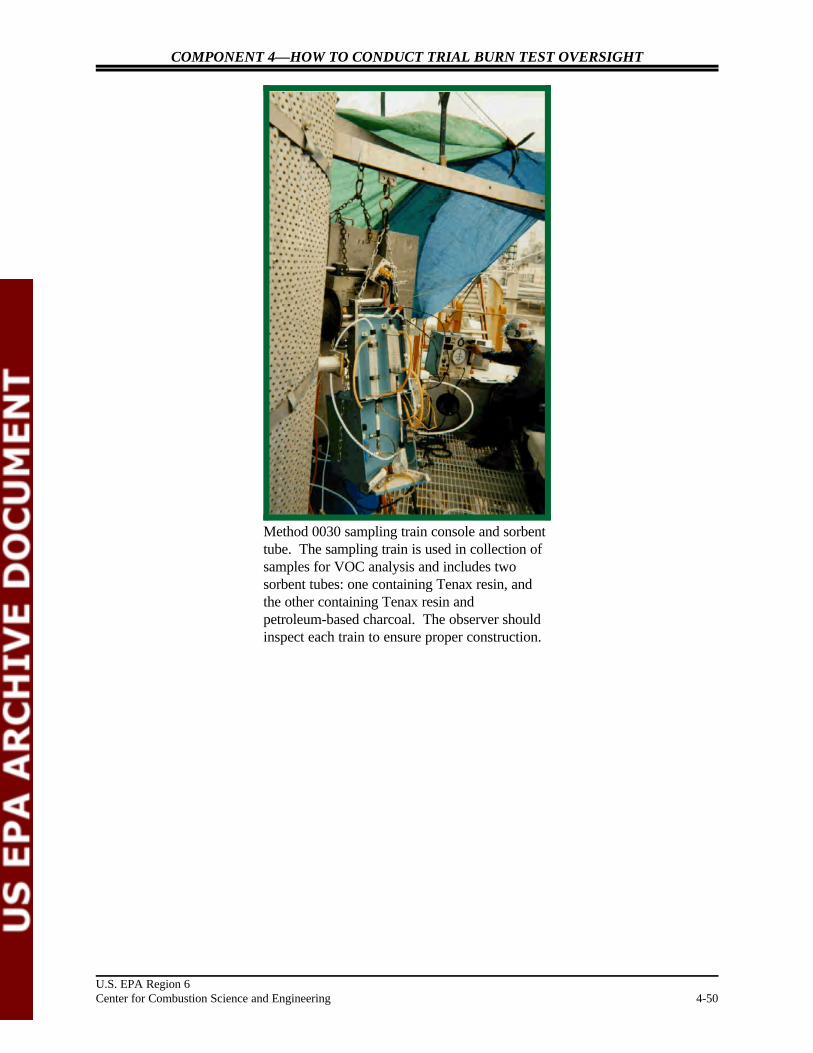
Method 0030 sampling train console and sorbenttube. The sampling train is used in collection ofsamples for VOC analysis and includes twosorbent tubes: one containing Tenax resin, andthe other containing Tenax resin andpetroleum-based charcoal. The observer shouldinspect each train to ensure proper construction.
COMPONENT 4—HOW TO CONDUCT TRIAL BURN TEST OVERSIGHT
U.S. EPA Region 6Center for Combustion Science and Engineering 4-51
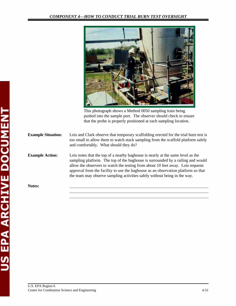
This photograph shows a Method 0050 sampling train beingpushed into the sample port. The observer should check to ensurethat the probe is properly positioned at each sampling location.
Example Situation: Lois and Clark observe that temporary scaffolding erected for the trial burn test istoo small to allow them to watch stack sampling from the scaffold platform safelyand comfortably. What should they do?
Example Action: Lois notes that the top of a nearby baghouse is nearly at the same level as thesampling platform. The top of the baghouse is surrounded by a railing and wouldallow the observers to watch the testing from about 10 feet away. Lois requestsapproval from the facility to use the baghouse as an observation platform so thatthe team may observe sampling activities safely without being in the way.
Notes:

COMPONENT 4—HOW TO CONDUCT TRIAL BURN TEST OVERSIGHT
U.S. EPA Region 6Center for Combustion Science and Engineering 4-52
This stack measures 4.7 square meters (50 square feet in cross-sectional area and 18 meters ”60 feet› high). The oversight teamshould verify the dimensions of each stack.
3.4.1 Reviewing Sampling Port Location
Regulation: No regulations are applicable to this section of the manual.
Guidance: No specific references are applicable to this section of the manual.
Explanation: For a representative measurement of the pollutant emission rate, a sampling portshould usually be located at least eight stack or duct diameters downstream and two diameters upstream from any flow disturbance—such as a bend, expansion,or contraction in the stack or from a visible flame. This rule of thumb is known asthe “eight-and two-diameter criterion.”
Check For: “ Stack diameter
“ Distance from sampling port to the nearest disturbance in upstream anddownstream directions
“ Process unit diagram
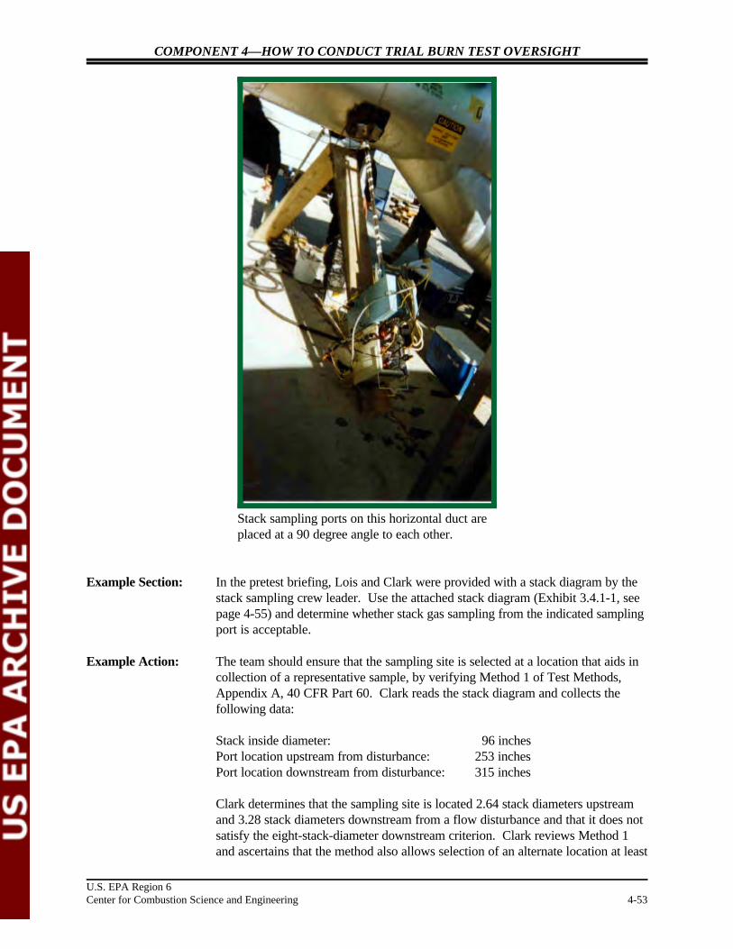
COMPONENT 4—HOW TO CONDUCT TRIAL BURN TEST OVERSIGHT
U.S. EPA Region 6Center for Combustion Science and Engineering 4-53
Stack sampling ports on this horizontal duct areplaced at a 90 degree angle to each other.
Example Section: In the pretest briefing, Lois and Clark were provided with a stack diagram by thestack sampling crew leader. Use the attached stack diagram (Exhibit 3.4.1-1, seepage 4-55) and determine whether stack gas sampling from the indicated samplingport is acceptable.
Example Action: The team should ensure that the sampling site is selected at a location that aids incollection of a representative sample, by verifying Method 1 of Test Methods,Appendix A, 40 CFR Part 60. Clark reads the stack diagram and collects thefollowing data:
Stack inside diameter: 96 inchesPort location upstream from disturbance: 253 inchesPort location downstream from disturbance: 315 inches
Clark determines that the sampling site is located 2.64 stack diameters upstreamand 3.28 stack diameters downstream from a flow disturbance and that it does notsatisfy the eight-stack-diameter downstream criterion. Clark reviews Method 1and ascertains that the method also allows selection of an alternate location at least

COMPONENT 4—HOW TO CONDUCT TRIAL BURN TEST OVERSIGHT
U.S. EPA Region 6Center for Combustion Science and Engineering 4-54
one-half stack diameter upstream and two stack diameters downstream from anyflow disturbance, if necessary.
The number of sampling ports in a stack varies, based on stack inside diameterand stack wall thickness. Generally, if the stack identification and stack wallthickness plus 6 inches is less than 10 feet, then two ports (located 90 degreesapart) are used. If the stack inside diameter and stack wall thickness plus 6 inchesis more than 10 feet, then four ports (located 90 degrees apart) are used.
Notes:

Traverse AM5/Orsat
Traverse BM5/Orsat
96.10 '
6 5 4 3 2 1 12 11 10 9 8 7
12
3
4
5
6
7
8
9
10
11
12
TraversePoint
123456789
101112
Distance fromInside Wall (inches)
2.026.4311.3315.9924.0034.1861.8272.0079.0184.6789.5793.98
96 '
213 '
360 '
253 '2.64 Diameters
315 '3.28 Diameters
Method 5SamplingLocation
V O S TVolatile Organic
Sampling Train
Sampling
COMPONENT 4—HOW TO CONDUCT TRIAL BURN TEST OVERSIGHT
U.S. EPA Region 6Center for Combustion Science and Engineering 4-55
EXHIBIT 3.4.1-1
EXAMPLE STACK DIAGRAM

COMPONENT 4—HOW TO CONDUCT TRIAL BURN TEST OVERSIGHT
U.S. EPA Region 6Center for Combustion Science and Engineering 4-56
3.4.2 Reviewing Cyclonic Flow Measurements
Regulation: No regulations are applicable to this section of the manual.
Guidance: No specific references are applicable to this section of the manual.
Explanation: To measure the pollutant emission rate, a sampling port should be located at apoint where the gas flow is not turbulent so that a representative stack gas samplecan be collected.
Check For: “ Cyclonic flow check data sheet
“ Cyclonic flow calculations
Example Situation: In the pretest briefing, the stack sampling crew leader provided Lois and Clarkwith a Cyclonic Flow Check Sheet. Using the attached Cyclonic Flow CheckSheet (Exhibit 3.4.2-1, see page 4-57), determine whether the port is acceptablefor sampling.
Example Action: To ensure that the sampling site is at a location where the direction of the stack gas flow is known, the team should confirm the absence of cyclonic flow. Lois reviews the cyclonic flow check sheet and checks the rotation angle, ", for all traverse points.
Lois determines that the average value of the rotation angle, ", is less than20 degrees, which indicates that the overall flow condition in the stack isacceptable.
Cyclonic flow usually exists (1) after certain APCS units, such as cyclones andventuri scrubbers; and (2) in stacks having tangential inlets or other configurationsthat induce swirling of the gas flow. Cyclonic flow problems can normally becorrected by inserting flow-straightening vanes or baffles in the stack that makestack gas flow parallel to stack walls.
Notes:
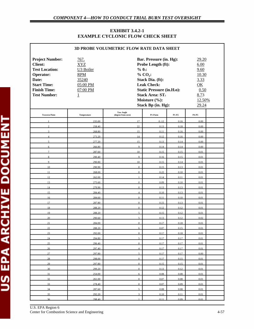
U.S. EPA Region 6Center for Combustion Science and Engineering 4-57
COMPONENT 4—HOW TO CONDUCT TRIAL BURN TEST OVERSIGHT
EXHIBIT 3.4.2-1EXAMPLE CYCLONIC FLOW CHECK SHEET
3D PROBE VOLUMETRIC FLOW RATE DATA SHEET
Project Number: 767. Bar. Pressure (in. Hg): 29.20Client: XYZ Probe Length (ft): 6.00Test Location: U3 Boiler % 02: 9.60Operator: RPM % CO : 10.302
Date: 35240 Stack Dia. (ft): 3.33Start Time: 05:00 PM Leak Check: OKFinish Time: 07:00 PM Static Pressure (in.H2o): 0.50Test Number: 1 Stack Area: ST2 8.73
Moisture (%): 12.50%Stack Bp (in. Hg): 29.24
Traverse Point Temperature (degree from zero) P1-Patm P1-P2 P4-P5 Yaw Angle
1 235.00 17 0..12 0.16 0.00
2 258.40 22 0.13 0.18 0.00
3 268.80 15 0.11 0.16 0.00
4 273.20 14 0.12 0.16 0.00
5 277.20 15 0.13 0.14 0.00
6 266.80 9 0.14 0.14 0.00
7 287.60 10 0.15 0.15 0.01
8 290.40 9 0.16 0.15 0.01
9 290.80 10 0.15 0.14 0.01
10 290.90 0 0.15 0.13 0.01
11 268.00 0 0.22 0.10 0.01
12 262.00 1 0.14 0.11 0.01
13 275.60 0 0.09 0.10 0.01
14 279.90 0 0.13 0.13 0.01
15 284.40 4 0.10 0.13 0.01
16 284.60 0 0.11 0.10 0.01
17 287.80 0 0.15 0.13 0.01
18 288.20 0 0.12 0.12 0.01
19 288.20 5 0.15 0.12 0.01
20 290.60 5 0.13 0.12 0.02
21 284.00 0 0.17 0.18 0.01
22 288.20 6 0.07 0.15 0.01
23 292.00 0 0.17 0.18 0.01
24 294.80 5 0.17 0.17 0.01
25 296.40 0 0.17 0.17 0.01
26 297.40 4 0.17 0.17 0.01
27 297.80 5 0.17 0.17 0.00
28 298.00 0 0.17 0.15 0.01
29 297.80 0 0.15 0.15 0.01
30 299.20 0 0.13 0.12 0.01
31 254.00 6 0.08 0.08 0.01
32 261.00 0 0.07 0.08 0.01
33 278.40 0 0.07 0.09 0.01
34 287.60 5 0.08 0.08 0.01
35 292.20 3 0.10 0.11 0.01
36 298.40 1 0.11 0.09 0.01

COMPONENT 4—HOW TO CONDUCT TRIAL BURN TEST OVERSIGHT
3D PROBE VOLUMETRIC FLOW RATE DATA SHEET
Project Number: 767. Bar. Pressure (in. Hg): 29.20Client: XYZ Probe Length (ft): 6.00Test Location: U3 Boiler % 02: 9.60Operator: RPM % CO : 10.302
Date: 35240 Stack Dia. (ft): 3.33Start Time: 05:00 PM Leak Check: OKFinish Time: 07:00 PM Static Pressure (in.H2o): 0.50Test Number: 1 Stack Area: ST2 8.73
Moisture (%): 12.50%Stack Bp (in. Hg): 29.24
Traverse Point Temperature (degree from zero) P1-Patm P1-P2 P4-P5 Yaw Angle
U.S. EPA Region 6Center for Combustion Science and Engineering 4-58
37 296.60 2 0.08 0.09 0.02
38 297.80 4 0.10 0.10 0.02
39 299.00 0 0.10 0.11 0.03
40 300.60 10 0.10 0.11 0.03
Average 283.99 4.6750 0.1280 0.1305 0.0090
COMPONENT 4—HOW TO CONDUCT TRIAL BURN TEST OVERSIGHT
U.S. EPA Region 6Center for Combustion Science and Engineering 4-59
3.4.3 Reviewing Traverse Point Location
Regulation: No regulations are applicable to this section of the manual.
Guidance: No specific references are applicable to this section of the manual.
Explanation: To ensure that the sample for measuring the pollutant emission rate isrepresentative, the team should collect the sample from each of the equal areas thatare obtained by dividing the cross section of the stack into equal areas.
Check For: “ Traverse point calculation sheet
Example Situation: In the pretest briefing, the stack sampling crew leader provided Lois and Clarkwith a Preliminary Velocity Traverse Data and Sampling Location Data sheet. Use the attached Preliminary Velocity Traverse Data and Sampling Location DataSheet (Exhibit 3.4.3-1, see page 4-60) to verify that traverse points are properlylocated.
Example Action: To ensure that a sample is collected uniformly from the entire cross section of thestack being sampled, the team should verify locations of traverse points. Lois(1) obtains from Clark the sampling site location relative to any flow disturbances,both upstream and downstream, (2) reads Figure 1-1 of Method 1 of TestMethods, Appendix A, 40 CFR Part 60, and (3) determines the following:
For a sampling port located 2.64 stack diameters upstream and 3.28 stackdiameters downstream from a flow disturbance, the minimum number of traversepoints required for particulate traverse is 24.
Lois understands that the 24 points may be located on two perpendiculardiameters, in accordance with Table 1-2 and the example shown in Figure 1-3 ofMethod 1 of Test Methods, Appendix A, 40 CFR Part 60. Lois verifies thePreliminary Velocity Traverse Data and Sampling Location Data Sheet andconcludes that the traverse point locations are acceptable.
Notes:
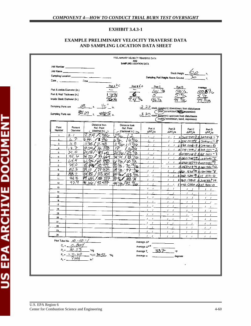
COMPONENT 4—HOW TO CONDUCT TRIAL BURN TEST OVERSIGHT
U.S. EPA Region 6Center for Combustion Science and Engineering 4-60
EXHIBIT 3.4.3-1
EXAMPLE PRELIMINARY VELOCITY TRAVERSE DATAAND SAMPLING LOCATION DATA SHEET

COMPONENT 4—HOW TO CONDUCT TRIAL BURN TEST OVERSIGHT
U.S. EPA Region 6Center for Combustion Science and Engineering 4-61
3.4.4 Reviewing Sampling Train Assembly
Regulation: No regulations are applicable to this section of the manual.
Guidance: No specific references are applicable to this section of the manual.
Explanation: Effective stack sampling is pivotal to trial burn success. One of the vital elementsof stack sampling is sampling train assembly. The oversight team must ensurethat trains are prepared in strict accordance with the SOPs of the test methods andthe approved TBP, RBP, or QAPP.
Check For: “ Availability of clean area for train assembly to prevent any contamination
“ Proper probe markings for traversing within the stack
“ Use of correct amount of reagents in the impingers
“ Storage of sorbent traps at below 20 CN
“ Use of proper connectors and sealants
“ Proper assembly of filter in the filter holder
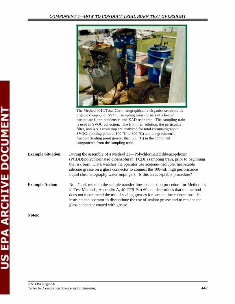
COMPONENT 4—HOW TO CONDUCT TRIAL BURN TEST OVERSIGHT
U.S. EPA Region 6Center for Combustion Science and Engineering 4-62
The Method 0010/Total Chromatographicable Organics semivolatileorganic compound (SVOC) sampling train consists of a heatedparticulate filter, condenser, and XAD resin trap. The sampling trainis used in SVOC collection. The front half solution, the particulatefilter, and XAD resin trap are analyzed for total chromatographicSVOCs (boiling point at 100 °C to 300 °C) and the gravimetricfraction (boiling point greater than 300 °C) in the combinedcomponents from the sampling train.
Example Situation: During the assembly of a Method 23—Polychlorinated dibenzopdioxin(PCDD)/polychlorinated dibenzofuran (PCDF) sampling train, prior to beginningthe risk burn, Clark watches the operator use acetone-insoluble, heat-stablesilicone grease on a glass connector to connect the 100-mL high performanceliquid chromatography water impingers. Is this an acceptable procedure?
Example Action: No. Clark refers to the sample transfer lines connection procedure for Method 23in Test Methods, Appendix A, 40 CFR Part 60 and determines that the methoddoes not recommend the use of sealing greases for sample line connections. Heinstructs the operator to discontinue the use of sealant grease and to replace theglass connector coated with grease.
Notes:

COMPONENT 4—HOW TO CONDUCT TRIAL BURN TEST OVERSIGHT
U.S. EPA Region 6Center for Combustion Science and Engineering 4-63
3.4.5 Observing Leak Checks Prior To Sampling
Regulation: No regulations are applicable to this section of the manual.
Guidance: No specific references are applicable to this section of the manual.
Explanation: Before a sampling run begins, each sampling train should be checked for leaks toensure that a sample of stack gases (1) enters the sampling train through the probenozzle, (2) travels through various components (such as the probe, filter, sorbenttrap, impingers, and pump) of the train, and (3) exits the train through the orificeat the end of the dry gas meter.
Check For: “ Visible breakage of glass components (visual inspection)
“ Leak in pitot tube
“ Leak in fully assembled sampling train
Example Section: Please see the following sampling train photograph and read the comments aboutthe sampling train leak check.

COMPONENT 4—HOW TO CONDUCT TRIAL BURN TEST OVERSIGHT
U.S. EPA Region 6Center for Combustion Science and Engineering 4-64
Check for leaks by watching the gas flow meterin the upper right corner of the meter box (blackrotating dial) and recording the amount of flowover time.
Example Comments: After the train is assembled, it is leak-checked by plugging the probe nozzle andpulling a 380-millimeter mercury (Hg) (15 inches Hg) vacuum. Observe the drygas meter dial and record the leakage rate. Leakage rates in excess of 4 percent ofthe average sampling rate or 0.02 cubic feet per minute are not acceptable, and thestack tester is required to fix the leak in the train before starting a sampling run.
Notes:

COMPONENT 4—HOW TO CONDUCT TRIAL BURN TEST OVERSIGHT
U.S. EPA Region 6Center for Combustion Science and Engineering 4-65
3.4.6 Observing Sampling Train Temperatures
Regulation: No regulations are applicable to this section of the manual.
Guidance: No specific references are applicable to this section of the manual.
Explanation: Stack gas test methods require that specific temperatures be maintained at variouslocations in the sampling train to ensure proper collection or sorption of pollutantsonto the collection media. It is, therefore, important to verify proper placement ofthermocouples at different locations in the sampling train.
Check For: “ Thermocouple locations
“ Proper condenser operation
“ Ice in the impinger box
Example Situation: Please see the following sampling train photograph and read the comments aboutobserving sampling train temperatures.

COMPONENT 4—HOW TO CONDUCT TRIAL BURN TEST OVERSIGHT
U.S. EPA Region 6Center for Combustion Science and Engineering 4-66
The temperature readout is located in the upperleft corner of this meter box. The dial below itchanges the readout between variousthermocouples attached to the sampling train. Ifthe dial is not labeled, the observer and thesampling train operator should determine corresponding thermal couples for each setting.
Method 23 requires that for efficient capture of PCDDs and PCDFs the XAD-2sorbent trap temperature never exceed 20 C during testing. During a stackN
sampling area survey, Lois looks at a Method 23—PCDD/PCDF sampling trainand observes that a thermocouple was placed in the middle of the shell side of thecondenser before the XAD-2 sorbent trap, and that no thermocouple was placed atthe gas entry point on the XAD-2 sorbent trap. Is this procedure correct?
Example Action: No. The thermocouple in the middle of the condenser reads the temperature ofrecirculating water rather than the temperature of the gas sample that is enteringthe XAD-2 sorbent trap. Lois instructs the train operator to move thethermocouple to either the tube side of the condenser or to the gas entry positionon the XAD-2 sorbent trap.

COMPONENT 4—HOW TO CONDUCT TRIAL BURN TEST OVERSIGHT
U.S. EPA Region 6Center for Combustion Science and Engineering 4-67
Notes:
COMPONENT 4—HOW TO CONDUCT TRIAL BURN TEST OVERSIGHT
U.S. EPA Region 6Center for Combustion Science and Engineering 4-68
3.4.7 Observing the Field Data Logsheet
Regulation: No regulations are applicable to this section of the manual.
Guidance: No specific references are applicable to this section of the manual.
Explanation: Stack gas flow and properties vary during trial burn testing, depending on processoperating conditions. To calculate average stack gas conditions that represent thestate of the stack gas during an entire test run, the sampling train console operatormust observe and record instantaneous stack gas conditions at regular intervalsduring the entire sampling period.
Check For: “ Number of sampling ports
“ Number of traverse points
“ Field Data Sheet
Example Situation: Observe the elements of the attached Field Data Sheet (Exhibit 3.4.7-1, see page4-69) and determine the number of traverse points and sampling ports used forstack gas sampling.
Example Comments: The Field Data Sheet shows that stack testing involved sampling from foursampling ports with six traverse points per port. Sampling was conducted for 1 hour in each port. Field data was recorded every 5 minutes for the entire sampling period. Leak checks were conducted once during every port change.
Notes:
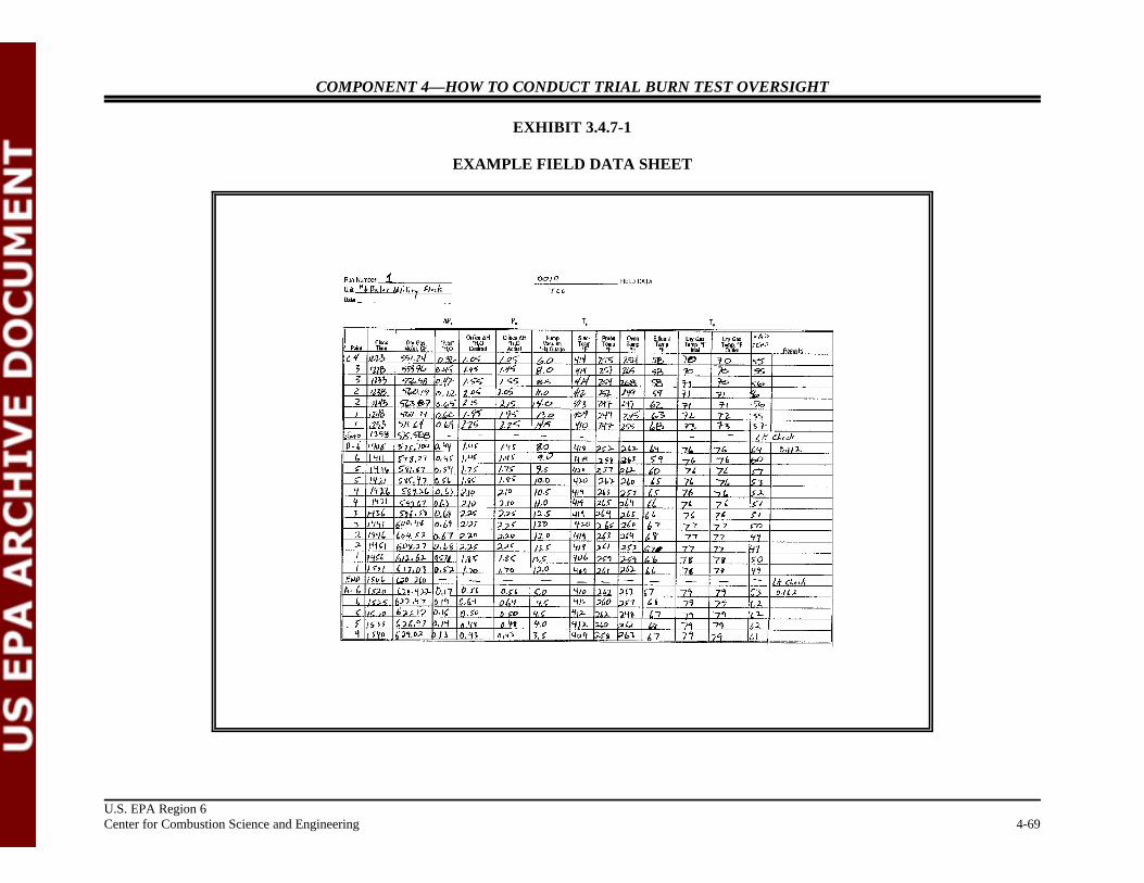
COMPONENT 4—HOW TO CONDUCT TRIAL BURN TEST OVERSIGHT
U.S. EPA Region 6Center for Combustion Science and Engineering 4-69
EXHIBIT 3.4.7-1
EXAMPLE FIELD DATA SHEET
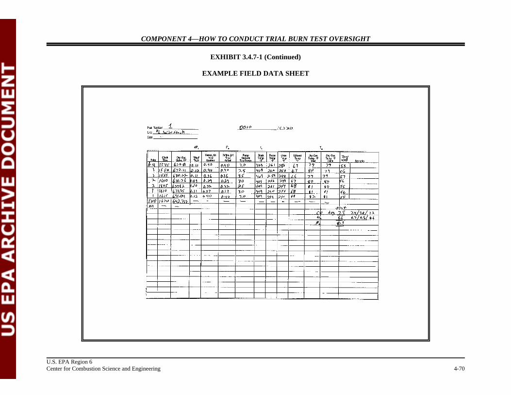
COMPONENT 4—HOW TO CONDUCT TRIAL BURN TEST OVERSIGHT
U.S. EPA Region 6Center for Combustion Science and Engineering 4-70
EXHIBIT 3.4.7-1 (Continued)
EXAMPLE FIELD DATA SHEET

COMPONENT 4—HOW TO CONDUCT TRIAL BURN TEST OVERSIGHT
U.S. EPA Region 6Center for Combustion Science and Engineering 4-71
3.4.8 Observing Leak Checks During Sampling
Regulation: No regulations are applicable to this section of the manual.
Guidance: No specific references are applicable to this section of the manual.
Explanation: Moving the sampling train between sampling ports is cumbersome, because(1) stack gas sampling trains consist of numerous glass components, and (2) thefront half of the train (probe and filter assembly) is usually heated to 120 ± 14ECor 248 ± 25EF. It is important to leak-check the trains whenever they are removedfrom, or inserted into, a sampling port. Although this check is not required byEPA methods, leak checking between port changes can help ensure that the datawill be valid by providing a check on the sampling during the run. Otherwise, thestack tests may not reveal a problem caused by movement during a port changeuntil the run is complete, thereby jeopardizing the viability of the sample.
Check For: “ Field Data Sheet
Example Situation: During the trial burn test, Lois and Clark were notified that the Method 23sampling train failed a leak check before the start of sampling in the secondsampling port. ABC Environmental reports that the sampling probe wasdisconnected from the filter holder. The stack sampling crew leader states that itmight have happened while the train was being moved from one port to the otherand recommend that sampling be continued after the leak is fixed. Lois askswhether a leak check was completed after the train was removed from the firstsampling port. She discovers that it was not. Should ABC Environmental beallowed to proceed with the sampling run?
Example Action: No. Because it cannot be established that the leak developed during the portchange, the sampling run should be invalidated. To determine when a leakdeveloped in the train, it is important to conduct a leak check immediately afterremoving the train from a port and again after moving the train to the next port.
Notes:
COMPONENT 4—HOW TO CONDUCT TRIAL BURN TEST OVERSIGHT
U.S. EPA Region 6Center for Combustion Science and Engineering 4-72
3.4.9 Observing Sampling Train Disassembly
Regulation: No regulations are applicable to this section of the manual.
Guidance: No specific references are applicable to this section of the manual.
Explanation: To minimize sample loss or contamination, probe pushers and train movers areexpected to handle the train with extreme caution during train operation and whiledisassembling and moving train components to the sample recovery area.
Check For: “ Whether the probe nozzle was allowed to touch the stack wall or theplatform
“ Whether a final leak check was conducted
“ Whether train components were disassembled without any breakage orloss of sample
“ Whether train components were properly capped, or sealed and labeled,before being transported to the sample recovery area
Example Situation: ABC Environmental reports that the final leak check of the Method 0010-SVOCsampling train failed, and that the leak rate was 0.04 cubic feet per minute. However, the leak check between port changes indicated no leak was present. Charlie of XYZ Company informs Lois and Clark that they would correct thesample volume on the basis of the leak rate and report the results. Is thisprocedure acceptable?
Example Comments: Yes. In case of a final leak check failure, Method 5 of Test Methods,Appendix A, 40 CFR, Part 60 provides options to either calculate a volumecorrection on the basis of the leak rate or repeat the sampling run. It is importantthat the stack sampling team inform the facility contact and permitting agency trialburn observers when a sampling train fails a leak check so that an agreed uponcourse of action can be taken. Had the leak rate been cause for concern, thefacility or agency may have required a repeat of the sampling run. It is much lessexpensive to repeat a sampling run while already mobilized for a trial burn, then toreturn to the facility at a later date.
Notes:

COMPONENT 4—HOW TO CONDUCT TRIAL BURN TEST OVERSIGHT
U.S. EPA Region 6Center for Combustion Science and Engineering 4-73
3.4.10 Completing Stack Sampling Checklists
Regulation: No regulations are applicable to this section of the manual.
Guidance: No specific references are applicable to this section of the manual.
Explanation: Observing stack gas sampling activities and documenting these observations aspart of the trial burn oversight report are important. Organized observation ofsampling procedures can be attained best with the use of checklists for specificprocedures being used. Specific items that should be checked for each of thesampling methods followed during a trial burn should be compiled in the form of achecklist for completion during stack sampling. Relevant checklists for observingsample train operation and recovery are included as Attachments A through N.
Check For: “ Method-specific checklists
Example Section: Attached is a checklist for Method 0010—Semivolatile Sampling Checklist(Exhibit 3.4.10-1, see Page 4-74).
Example Comments: The oversight team should read and understand items identified in the checklistbefore arriving at the stack testing platform for observation of stack samplingactivities.
Notes:

COMPONENT 4—HOW TO CONDUCT TRIAL BURN TEST OVERSIGHT
U.S. EPA Region 6Center for Combustion Science and Engineering 4-74
EXHIBIT 3.4.10-1METHOD 0010 SEMIVOLATILE POHC AND PIC ORGANICS SAMPLING CHECKLIST
Facility Name: Run Number: Observer Signature: Test No./Description: Run Start Time: Unit: Run Stop Time: Date of Observation:
Observation / Requirement YES NO Comment
Did the train components appear to be clean and were all glasswareopenings covered with Teflon film, aluminum foil, or noncontaminating®
caps before the train was assembled?
Was the train assembled by personnel in a manner that minimizedcontamination potential?
Was the train constructed of the components and materials identified inMethod 0010 (See Figure 0010: nozzle, heated probe, particulate filter, onecondenser and recirculating cooling water system, one XAD-2 resin trap,four impingers, control console, etc.)?
Were the dry gas meter, thermocouples, nozzle, and critical orifice devices Dry gas metercalibrated prior to the test? If yes, provide the calibration dates in the ThermocouplesComment column. If available, attach a copy of the calibration records. Critical orifice
Nozzle
Were weather conditions adverse to sampling (rain, snow, etc.)? If so,describe the measures taken to protect the sampling equipment in theComment column.
Was the sampling area (i.e., platform) kept clean and orderly during therun?
Were the traverse sample points determined in accordance with Method 1?
Was a cyclonic flow check made before the start of testing? If yes, recordthe date and time the check was completed in the Comment column.
Were stack gas oxygen, carbon dioxide, and carbon monoxideconcentrations measured by orsat, fyrite, or CEMS?
Was the manometer leveled and zeroed before the start of sampling? Wereperiodic checks made by the operator during the test run?

COMPONENT 4—HOW TO CONDUCT TRIAL BURN TEST OVERSIGHT
EXHIBIT 3.4.10-1 (Continued)METHOD 0010 SEMIVOLATILE POHC AND PIC ORGANICS SAMPLING CHECKLIST
Facility Name: Run Number: Observer Signature: Test No./Description: Run Start Time: Unit: Run Stop Time: Date of Observation:
Observation / Requirement YES NO Comment
U.S. EPA Region 6Center for Combustion Science and Engineering 4-75
Was the stack static pressure properly measured? At what traverse pointwas this determined?
Was the sampling time uniform at each traverse sample point?
Was the total sampling time at least 120 minutes?
Were at least 3 dry standard cubic meters of gas sample collected duringthe run?
Were the sample train and console adequately monitored by operators anddid the operators properly log sampling data on field data sheets during thetest run?

COMPONENT 4—HOW TO CONDUCT TRIAL BURN TEST OVERSIGHT
EXHIBIT 3.4.10-1 (Continued)METHOD 0010 SEMIVOLATILE POHC AND PIC ORGANICS SAMPLING CHECKLIST
Facility Name: Run Number: Observer Signature: Test No./Description: Run Start Time: Unit: Run Stop Time: Date of Observation:
Observation / Requirement YES NO Comment
U.S. EPA Region 6Center for Combustion Science and Engineering 4-76
Were dry gas meter readings recorded at each traverse sample point?
Was the nozzle sealed with Teflon film, aluminum foil, or a®
noncontaminating cap after being removed from the stack at the completionof the run and during leak checks?
Was particulate matter carefully wiped from the external surfaces of theprobe at the completion of the run?
Was the temperature of the filter box and sample probe maintained at 248 ±25EF throughout the test run?
Did protracted or frequent “holds” occur during the sampling run? If so,describe the apparent cause and duration in the Comment column.
Inspect the field data sheets. Are they clear and completely filled out?
Were XAD-2 Resin Tubes packed, and spiked by the analytical laboratorywith sampling surrogates for semivolatiles?
Were Field Blanks collected during each run?
Was the Blank Train set up identically to the actual sampling trains andplaced on the stack or at the base of the stack for the duration of onecomplete sampling run? Was the Blank Train leak checked and heated totemperature throughout the run?
Were Reagent Blanks collected once during the three runs?
Were Trip Blanks collected once for each sample shipment?
Were spiked Resin Blanks prepared and analyzed before the trial burn?

COMPONENT 4—HOW TO CONDUCT TRIAL BURN TEST OVERSIGHT
EXHIBIT 3.4.10-1 (Continued)METHOD 0010 SEMIVOLATILE POHC AND PIC ORGANICS SAMPLING CHECKLIST
Facility Name: Run Number: Observer Signature: Test No./Description: Run Start Time: Unit: Run Stop Time: Date of Observation:
U.S. EPA Region 6Center for Combustion Science and Engineering 4-77
GENERAL OBSERVATIONS AND COMMENTS
COMPONENT 4—HOW TO CONDUCT TRIAL BURN TEST OVERSIGHT
U.S. EPA Region 6Center for Combustion Science and Engineering 4-78
3.5 OBSERVING WASTE FEED AND AIR POLLUTION CONTROL DEVICE EFFLUENTSAMPLING
Regulation: No regulations are applicable to this section of the manual.
Guidance: No specific references are applicable to this section of the manual.
Explanation: To assess the performance of a combustion unit, samplers should collect samples ofwaste feed and APCS effluent streams with stack gas samples. To ensure collection ofa representative sample, samplers should collect samples in strict accordance withSOPs identified in the approved TBP, RBP, and QAPP.
Check For: “ Whether the liquid in the sampling line was drained before a sample was collected
“ Whether there are any visible air bubbles in the VOA vials
“ Whether samples are collected in accordance with procedures specified in theapproved TBP, RBP, and QAPP and at the specified frequency
“ Whether logsheets—showing date, time, run number, and sampler name—arecompleted for each sample
“ Whether sample containers are labeled—showing date, time, and identificationnumber—with a permanent marker pen
“ Whether sample containers are handled and stored in accordance with proceduresspecified in the approved TBP, RBP, and QAPP
“ Whether sample traceability and chain-of-custody records are being initiated andmaintained for each sample

COMPONENT 4—HOW TO CONDUCT TRIAL BURN TEST OVERSIGHT
U.S. EPA Region 6Center for Combustion Science and Engineering 4-79
Waste feed sampling
Example Section: Attached are example Waste Feed Sample Logsheet (Exhibit 3.5-1, seepage 4-80) and Chain of Custody Record (Exhibit 3.5-2, see page 4-81) forms.
Example Comments: To the extent practicable, all sampling activities should be observed a number oftimes throughout the trial burn testing. Each type of sampling should be observedduring the first run, at a minimum, to ensure that sampling techniques are inaccordance with the approved TBP and QAPP.
Notes:

COMPONENT 4—HOW TO CONDUCT TRIAL BURN TEST OVERSIGHT
U.S. EPA Region 6Center for Combustion Science and Engineering 4-80
EXHIBIT 3.5-1
EXAMPLE WASTE FEED SAMPLE LOGSHEET
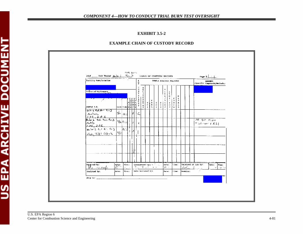
COMPONENT 4—HOW TO CONDUCT TRIAL BURN TEST OVERSIGHT
U.S. EPA Region 6 Center for Combustion Science and Engineering 4-81
EXHIBIT 3.5-2
EXAMPLE CHAIN OF CUSTODY RECORD
COMPONENT 4—HOW TO CONDUCT TRIAL BURN TEST OVERSIGHT
U.S. EPA Region 6Center for Combustion Science and Engineering 4-82
3.6 OBSERVING PROCESS OPERATION ACTIVITIES
Regulation: No regulations are applicable to this section of the manual.
Guidance: No specific references are applicable to this section of the manual.
Explanation: The oversight team must periodically observe and document process operatingconditions during the trial burn to ascertain whether the BIF unit is being operatedin accordance with target operating conditions identified in the approved TBP orRBP. All process operating parameters for which permit limits may beestablished should be measured during the test.
Check For: “ Process
“ Combustion chamber temperature“ Combustion gas temperature“ Combustion chamber atomization and burner pressure“ Combustion gas velocity“ Excess air flow rate“ Kiln rotational speed“ CO concentration“ O concentration2
“ Total hydrocarbon concentration“ Unit production rates
“ Waste feed
“ Feed rates“ Chlorine input rates“ Ash loading rates“ Feed spiking compound rates“ Atomization fluid pressure“ Combustion chamber atomization and burner pressure
“ Residue generation rates
“ Bottom ash “ Fly ash “ Scrubber mud and solid residue
“ Cyclone
“ Pressure drop“ Inlet temperature
COMPONENT 4—HOW TO CONDUCT TRIAL BURN TEST OVERSIGHT
U.S. EPA Region 6Center for Combustion Science and Engineering 4-83
“ Dry scrubber
“ Reagent flow rate“ Atomizer rotational speed“ Atomizer nozzle pressure“ Inlet temperature“ Outlet temperature
“ Baghouse
“ Pressure drop“ Inlet temperature
“ Electrostatic precipitator
“ Voltage“ Current“ Sparking rate“ Flue gas flow rate
“ Mist Eliminator
“ Pressure drop
“ Quencher
“ Exit temperature“ Water flow rate
“ Packed tower scrubber
“ Pressure drop“ Liquid flow rate“ Effluent pH
“ Venturi scrubber
“ Pressure drop“ Liquid flow rate“ Effluent pH“ Gas-to-liquid flow rate ratio“ Scrubbing reagent concentration“ Scrubbing reagent flow rate“ Maximum solids content in effluent
“ Whether the data acquisition recorder (DAR) is a digital or an analog system
“ Whether the digital readout agrees closely with the value on the strip chartrecorder
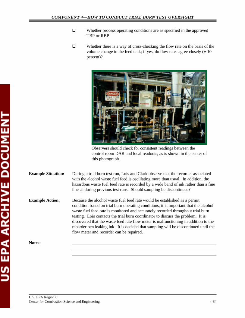
COMPONENT 4—HOW TO CONDUCT TRIAL BURN TEST OVERSIGHT
U.S. EPA Region 6Center for Combustion Science and Engineering 4-84
Observers should check for consistent readings between thecontrol room DAR and local readouts, as is shown in the center ofthis photograph.
“ Whether process operating conditions are as specified in the approvedTBP or RBP
“ Whether there is a way of cross-checking the flow rate on the basis of thevolume change in the feed tank; if yes, do flow rates agree closely (± 10percent)?
Example Situation: During a trial burn test run, Lois and Clark observe that the recorder associatedwith the alcohol waste fuel feed is oscillating more than usual. In addition, thehazardous waste fuel feed rate is recorded by a wide band of ink rather than a fineline as during previous test runs. Should sampling be discontinued?
Example Action: Because the alcohol waste fuel feed rate would be established as a permitcondition based on trial burn operating conditions, it is important that the alcoholwaste fuel feed rate is monitored and accurately recorded throughout trial burntesting. Lois contacts the trial burn coordinator to discuss the problem. It isdiscovered that the waste feed rate flow meter is malfunctioning in addition to therecorder pen leaking ink. It is decided that sampling will be discontinued until theflow meter and recorder can be repaired.
Notes:
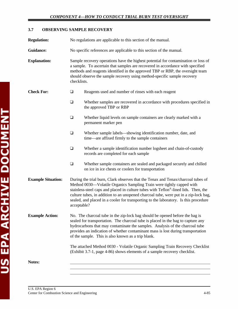
COMPONENT 4—HOW TO CONDUCT TRIAL BURN TEST OVERSIGHT
U.S. EPA Region 6Center for Combustion Science and Engineering 4-85
3.7 OBSERVING SAMPLE RECOVERY
Regulation: No regulations are applicable to this section of the manual.
Guidance: No specific references are applicable to this section of the manual.
Explanation: Sample recovery operations have the highest potential for contamination or loss ofa sample. To ascertain that samples are recovered in accordance with specifiedmethods and reagents identified in the approved TBP or RBP, the oversight teamshould observe the sample recovery using method-specific sample recoverychecklists.
Check For: “ Reagents used and number of rinses with each reagent
“ Whether samples are recovered in accordance with procedures specified inthe approved TBP or RBP
“ Whether liquid levels on sample containers are clearly marked with apermanent marker pen
“ Whether sample labels—showing identification number, date, andtime—are affixed firmly to the sample containers
“ Whether a sample identification number logsheet and chain-of-custodyrecords are completed for each sample
“ Whether sample containers are sealed and packaged securely and chilledon ice in ice chests or coolers for transportation
Example Situation: During the trial burn, Clark observes that the Tenax and Tenax/charcoal tubes ofMethod 0030—Volatile Organics Sampling Train were tightly capped withstainless-steel caps and placed in culture tubes with Teflon -lined lids. Then, the®
culture tubes, in addition to an unopened charcoal tube, were put in a zip-lock bag,sealed, and placed in a cooler for transporting to the laboratory. Is this procedureacceptable?
Example Action: No. The charcoal tube in the zip-lock bag should be opened before the bag issealed for transportation. The charcoal tube is placed in the bag to capture anyhydrocarbons that may contaminate the samples. Analysis of the charcoal tubeprovides an indication of whether contaminant mass is lost during transportationof the sample. This is also known as a trip blank.
The attached Method 0030 - Volatile Organic Sampling Train Recovery Checklist(Exhibit 3.7-1, page 4-86) shows elements of a sample recovery checklist.
Notes:

COMPONENT 4—HOW TO CONDUCT TRIAL BURN TEST OVERSIGHT
EXHIBIT 3.7-1
METHOD 0030 VOLATILE ORGANIC SAMPLING TRAIN RECOVERY CHECKLIST
Facility Name: Unit: Observer: Test No. / Description: Run No.: Date: Run Start Time: Run Stop Time:
U.S. EPA Region 6Center for Combustion Science and Engineering 4-86
Observation / Requirement YES NO Comment
Was the sampling train disassembled at the sampling port location? If so, werethe openings of the test train components (adsorbent traps, condensate trap,and so on) sealed before being relocated to the recovery area? Werecomponents sealed with Teflon tape or noncontaminating caps?®
Was the condensate sample collected for each tube set?
Was the total condensate sample collected at the conclusion of the test run?
Were the openings of the adsorbent traps capped after removal from thesampling train and replaced into the original storage vials?
Was the condensate sample collected into an amber glass VOA vial with aTeflon septum screw cap?®
Was organic-free water added to the condensate VOA vial to ensure that no airbubbles were present?
Were at least three tube sets collected during the test run?
Was a fourth tube set collected during the test run for archiving purposes?
Was a reagent blank of the organic-free water collected according to thesampling plan? If so, indicate the sample identifier name in the Commentcolumn.
Was a blank sampling train prepared and recovered at the sampling location? How long did the blank train remain intact before recovery?
Were the condensate VOA vial and adsorbent tubes properly labeled and storedon ice promptly after recovery?
Was a trip blank pair of adsorbent tubes included with each sample shipmentto the laboratory?
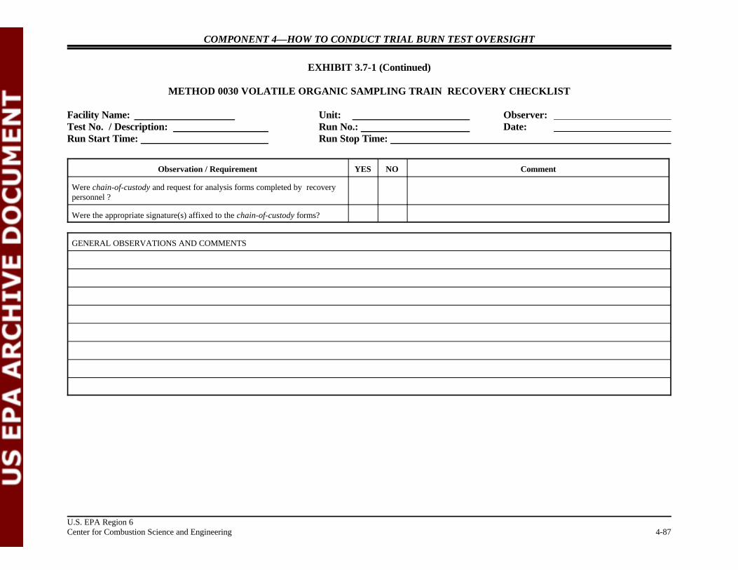
COMPONENT 4—HOW TO CONDUCT TRIAL BURN TEST OVERSIGHT
EXHIBIT 3.7-1 (Continued)
METHOD 0030 VOLATILE ORGANIC SAMPLING TRAIN RECOVERY CHECKLIST
Facility Name: Unit: Observer: Test No. / Description: Run No.: Date: Run Start Time: Run Stop Time:
Observation / Requirement YES NO Comment
U.S. EPA Region 6Center for Combustion Science and Engineering 4-87
Were chain-of-custody and request for analysis forms completed by recoverypersonnel ?
Were the appropriate signature(s) affixed to the chain-of-custody forms?
GENERAL OBSERVATIONS AND COMMENTS

COMPONENT 4—HOW TO CONDUCT TRIAL BURN TEST OVERSIGHT
U.S. EPA Region 6Center for Combustion Science and Engineering 4-88
3.8 COLLECTING TRIAL BURN TEST INFORMATION
Regulation: No regulations are applicable to this section of the manual.
Guidance: No specific references are applicable to this section of the manual.
Explanation: It is important to obtain copies of all field data and review them, if possible, beforethe start of the next run or before leaving the facility. Isokinetic sampling involvesuniformly sampling particulates or gases in a stack. Uniform sampling isachieved by maintaining the velocity of the gas stream entering the probe nozzle ata level that is exactly equal to the stack gas velocity. An isokinetic sampling runis valid only if the average sampling rate during the run is ± 10 percent of theisokinetic sampling rate. Before the start of the next run, stack sampling field datasheets should be compiled, and calculations must be verified.
Check For: “ Whether gas temperatures at different locations in the sampling trainduring the trial burn test are consistently within the ranges indicated inspecific test methods
“ Whether the volumes of stack gas samples collected remained consistentlywithin the ranges indicated in specific test methods
“ Whether isokinetic sampling variations are within ± 10 percent of theisokinetic sampling rate
“ Whether all sampling trains have passed final leak checks
“ Whether process operating conditions maintained during the trial burn testconform with process conditions in the approved TBP or RBP
“ Whether waste feed and APCS effluent samples are collected inconformance with procedures specified in the approved TBP or RBP
Example Situation: Briefly review the attached Field Data Calculation Sheet (Exhibit 3.8-1, see page4-89), and determine whether the sampling flow rate during the test run wasacceptable.
Example Action: Yes. The stack gas sampling rate was about 95.5 percent of the isokineticsampling rate, which remains in the acceptable isokinetic variation range of 90 to110 percent.
Notes:

COMPONENT 4—HOW TO CONDUCT TRIAL BURN TEST OVERSIGHT
U.S. EPA Region 6Center for Combustion Science and Engineering 4-89
EXHIBIT 3.8-1
EXAMPLE FIELD DATA CALCULATION SHEET

COMPONENT 4—HOW TO CONDUCT TRIAL BURN TEST OVERSIGHT
U.S. EPA Region 6Center for Combustion Science and Engineering 4-90
3.9 CONDUCTING DAILY MEETINGS
Regulation: No regulations are applicable to this section of the manual.
Guidance: No specific references are applicable to this section of the manual.
Explanation: Trial burns are both time-intensive and expensive. To (1) assess progress,(2) identify any changes to and deviations from the approved TBP or RBP, and(3) evaluate the impact of changes or deviations on the quality of test data, theoversight team should meet with responsible facility and test personnel at regularintervals and when the oversight team feels that a briefing is necessary to resolvean issue.
Check For: During daily meetings, the oversight team should summarize the following:
“ Trial burn test runs planned for the day
“ Major changes to or deviations from the approved TBP or RBP
“ Problems encountered and their resolution
“ Trial burn progress and completion schedule
Example Situation: During sample recovery of a Method 23A sampling train for PCDDs/PCDFs,Clark observes that front-half and back-half rinses contained three acetone rinsesfollowed by three methylene chloride rinses. Clark recalls that Method 23Arequires two toluene rinses to follow the three acetone rinses and three methylenechloride rinses in the sample recovery of front-half and back-half components. Should Clark wait until the end of the day to brief the testing team on the recoveryof the Method 23A sampling train?
Example Action: No. Clark informs the stack testing coordinator immediately regarding thedeviation to the method and requires that the correct procedure be followed. Tothe extent practicable, problems and issues should be discussed and resolvedimmediately in the field through consultations with cognizant regulatory personnel.
Notes:

COMPONENT 4—HOW TO CONDUCT TRIAL BURN TEST OVERSIGHT
U.S. EPA Region 6Center for Combustion Science and Engineering 4-91
3.10 CONDUCTING FIELD DOCUMENTATION ACTIVITIES
Regulation: No regulations are applicable to this section of the manual.
Guidance: No specific references are applicable to this section of the manual.
Explanation: The oversight team should keep comprehensive notes of daily activities throughoutthe trial burn. Good field documentation helps in preparing a detailed TBO reportthat would assist the trial burn report reviewer in evaluating the validity andrepresentativeness of the trial burn tests and the permit writer in establishingpermit limits based on process operating conditions observed during the test. Theoversight team should also obtain photographs of the process unit being tested,waste feed tank, stack sampling platform, and all sampling activities during thetrial burn.
Check For: Documentation of field activities should include the following:
“ Process operating parameters for each run
“ General impressions of stack sampling activities
“ General impressions of stack sample recovery activities
“ General impressions of waste feed and APCS sampling activities
“ Deviations from and changes to the approved TBP or RBP
Photodocumentation should include the following:
“ BIF unit being tested
“ Stack showing any obstructions to the flow of stack gases
“ Waste feed storage tanks
“ APCS units
“ Location of stack sampling ports and sampling platform
“ Location of CEMS probe
“ Location of waste feed sampling
“ Location of waste feed spiking
“ Various stack sampling trains used during the trial burn
“ Waste spiking system

COMPONENT 4—HOW TO CONDUCT TRIAL BURN TEST OVERSIGHT
U.S. EPA Region 6Center for Combustion Science and Engineering 4-92
“ Waste feed and APCS sampling systems
“ Modifications to or deviations from any standard sampling systems andprocedures identified in the approved TBP or RBP
Example Situation: Lois and Clark notice that hazardous waste feed and APCS samples for SVOCanalysis were collected in clear glass bottles and were not stored on ice or in icechests throughout the first trial burn test run sampling period. Lois does not recallwhether collection of hazardous waste feed samples in clear glass bottles is anacceptable procedure. Lois photographs the waste feed sampling system.
Lois refers to the approved TBP and QA/QC handbook and determines thatsamples should have been collected in amber glass bottles and stored on ice in icechests. Lois requests that the facility follow procedures identified in the approvedTBP for the remainder of trial burn test runs. The facility uses amber glassbottles for waste feed sample collection and stores them on ice in ice chests for allremaining test runs. Lois photographs the modified waste feed sampling system.
Example Action: Lois and Clark include photographs of both waste feed sampling systems in theTBO report and recommend that trial burn report reviewer evaluate the impacts ofthis deviation on data quality of the first trial burn test run.
Notes:

COMPONENT 4—HOW TO CONDUCT TRIAL BURN TEST OVERSIGHT
U.S. EPA Region 6Center for Combustion Science and Engineering 4-93
3.11 OBSERVING AUDIT GAS SAMPLING
Regulation: No regulations are applicable to this section of the manual.
Guidance: No specific references are applicable to this section of the manual.
Explanation: An audit is an assessment of the data by estimating accuracy. Generally, an audit isconducted either to determine the efficacy of a source testing organization’s samplingprocedures or to quantitatively evaluate the data produced by sample collection,sample recovery, sample analysis, and data processing. CEMS are also audited byintroducing known concentrations of gases received from EPA. The results of theperformance audit are submitted along with the trial burn results.
Check For: “ Relative Accuracy Test Audit — Absolute mean difference between gasconcentration and the value determined by reference method, plus the 2.5 percenterror confidence coefficient of a series of tests divided by the mean of the referencemethod tests.
“ Cylinder Gas Audit — Challenge the CEMS with an audit gas of knownconcentration at two points within 20 to 30 percent value and 50 to 60 percent of aknown value and assess the accuracy of CEMS by determining the differencebetween the actual concentration of the audit gas and the concentration indicatedby the monitor. These audit gas cylinders are available from most major gassuppliers.
“ Volatile Organic Sampling Train (VOST) — A gas sample containing principalorganic hazardous constituents (POHC) is passed from an audit gas cylinder into aglass manifold. A portion of the gas is drawn through a VOST in accordance withmethod specifications. Collected POHCs are analyzed by the methods identified inthe TBP. The analytical results are compared to the known concentrations. TheVOST audit gas cylinder is available from Ellen Strieb at U.S. EPA ResearchTriangle Park (RTP), 919-544-7834. This agency can be contacted only by EPAor state agencies to request a VOST audit gas. It is suggested that 4 weeks leadtime be provided for procurement.
.“ PCDDs and PCDFs Audit — A performance audit sample containing tetra
through octa-isomers of PCDD and PCDF is analyzed in accordance with themethods identified in the TBP. The analytical results are compared to the knownconcentrations. These performance audit samples are available from EasterCoptedge at U.S. EPA RTP, 919-541-7863. There have been times in the pastwhen inadequate funding severely delayed or suspended audit sample availability. It is suggested that 4 to 6 weeks lead time be provided to obtain the audit sample.

COMPONENT 4—HOW TO CONDUCT TRIAL BURN TEST OVERSIGHT
U.S. EPA Region 6Center for Combustion Science and Engineering 4-94
Example CEMS probe location on a stack. During a cylinder gas audit, the observer shouldensure that the audit gas passes through the entiregas conditioning system. This should ideallyinclude as much of the sample line (after theprobe) as possible.
Example Situation: During sampling of the VOST audit gas cylinder, Lois observes that (1) auditgases are passed into a heated glass manifold, and (2) a portion of the gases aredrawn from the manifold at a rate of 1.0 liter per minute into a pair of sorbenttubes. Lois notices that the condensers positioned before the sorbent tubes do nothave water recirculating through them. Is this an acceptable procedure ?
Example Comments: A letter accompanying the audit gas cylinders describes the origin of the cylindergas, purpose of the audit, and procedures/instructions to be followed for the audit. In reviewing the instructions for sampling POHC from the audit gas cylinder usingVOST, Lois realizes that the volume of sample for any pair of sorbent trapsshould not exceed 10 liters and that the gas stream at the inlet to the first sorbenttrap should be maintained at 20EC during sample collection. Lois contacts thetrial burn coordinator and requests that the VOST operator circulate chilled waterthrough the condensers and install a thermocouple that indicates the temperature ofthe gas stream at the inlet to the first sorbent trap.

COMPONENT 4—HOW TO CONDUCT TRIAL BURN TEST OVERSIGHT
U.S. EPA Region 6Center for Combustion Science and Engineering 4-95
Notes:
COMPONENT 4—HOW TO CONDUCT TRIAL BURN TEST OVERSIGHT
U.S. EPA Region 6Center for Combustion Science and Engineering 4-96
4.0 PREPARING THE OVERSIGHT REPORT
Regulation: No regulations are applicable to this section of the manual.
Guidance: No specific references are applicable to this section of the manual.
Explanation: The trial burn oversight report (1) summarizes sampling and process controloperations, (2) identifies any deviations from or changes to methods in theapproved TBP, (3) describes problems encountered and their resolution,(4) comments on the representativeness of the trial burn and the data quality, and(5) provides recommendations on permit conditions that should be specified forthe facility. The TBO report also documents observations and field notes of theobservers and data collected during the trial burn.
Check For: The following is an example outline for a typical TBO report.
“ Overview of the TBO
“ Facility description
“ Engineering description“ Characterization of hazardous waste feed stream“ Process operating conditions“ CEMS
“ Implementation of the trial burn
“ Test conditions“ Stack sampling“ Waste feed sampling“ Other sampling activities“ Sample analysis “ Process monitoring, control, and DAR“ Trial burn completion schedule
“ Field Observations
“ Daily activities of observers“ General impressions of observers“ Deviations from approved TBP or RBP“ Other problems and issues and their resolution“ Conclusions and recommendations
Example Situation: Following is an issue that Lois and Clark encountered during a trial burn.
“During the first run of the Utility Boiler, Method 0050 and particle sizedistribution sampling trains were put on hold for a short period when the feed tothe boiler was tripped. The run was completed when waste feed to the boilerrestarted at a substantially reduced feed rate.”
COMPONENT 4—HOW TO CONDUCT TRIAL BURN TEST OVERSIGHT
U.S. EPA Region 6Center for Combustion Science and Engineering 4-97
Example Action: In the TBO report, Lois and Clark recommend that the XYZ Company evaluatehow the waste feed cutoff during run one impacts the emission rates of particulatematter, hydrogen chloride, and chlorine gas. They also ask the facility to comparethese emission rates with those of the second and third risk burn runs.
Notes:

ATTACHMENT A
METHOD 0010 SEMIVOLATILE POHC AND PIC ORGANICS SAMPLING CHECKLIST
(5 Sheets)

4-A-1
METHOD 0010 SEMIVOLATILE POHC AND PIC ORGANICS SAMPLING CHECKLIST
Facility Name: Run Number: Observer Signature: Test No./Description: Run Start Time: Unit: Run Stop Time: Date of Observation:
Observation / Requirement YES NO Comment
Did the train components appear to be clean and were all glassware openingscovered with Teflon film, aluminum foil, or noncontaminating caps before®
the train was assembled?
Was the train assembled by personnel in a manner that minimizedcontamination potential?
Was the train constructed of the components and materials identified inMethod 0010 (See Figure 0010: nozzle, heated probe, particulate filter, onecondenser and recirculating cooling water system, one XAD-2 resin trap,four impingers, control console, etc.)?
Were the dry gas meter, thermocouples, nozzle, and critical orifice devices Dry gas metercalibrated prior to the test? If yes, provide the calibration dates in the ThermocouplesComment column. If available, attach a copy of the calibration records. Critical orifice
Nozzle
Were weather conditions adverse to sampling (rain, snow, etc.)? If so,describe the measures taken to protect the sampling equipment in theComment column.
Was the sampling area (i.e., platform) kept clean and orderly during the run?
Were the traverse sample points determined in accordance with Method 1?
Was a cyclonic flow check made before the start of testing? If yes, record thedate and time the check was completed in the Comment column.
Were stack gas oxygen, carbon dioxide, and carbon monoxide concentrationsmeasured by orsat, fyrite, or CEMS?
Was the manometer leveled and zeroed before the start of sampling? Wereperiodic checks made by the operator during the test run?
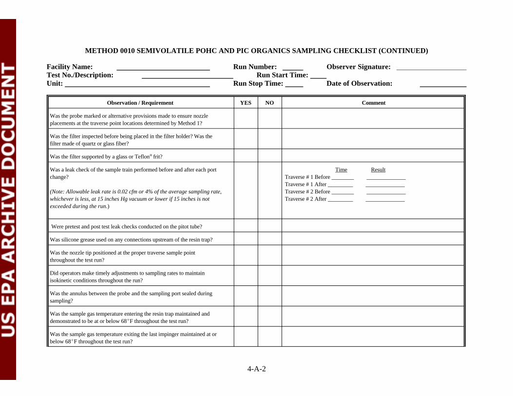
METHOD 0010 SEMIVOLATILE POHC AND PIC ORGANICS SAMPLING CHECKLIST (CONTINUED)
Facility Name: Run Number: Observer Signature: Test No./Description: Run Start Time: Unit: Run Stop Time: Date of Observation:
Observation / Requirement YES NO Comment
4-A-2
Was the probe marked or alternative provisions made to ensure nozzleplacements at the traverse point locations determined by Method 1?
Was the filter inspected before being placed in the filter holder? Was thefilter made of quartz or glass fiber?
Was the filter supported by a glass or Teflon frit?®
Was a leak check of the sample train performed before and after each port Time Resultchange? Traverse # 1 Before
(Note: Allowable leak rate is 0.02 cfm or 4% of the average sampling rate, Traverse # 2 Before whichever is less, at 15 inches Hg vacuum or lower if 15 inches is not Traverse # 2 After exceeded during the run.)
Traverse # 1 After
Were pretest and post test leak checks conducted on the pitot tube?
Was silicone grease used on any connections upstream of the resin trap?
Was the nozzle tip positioned at the proper traverse sample pointthroughout the test run?
Did operators make timely adjustments to sampling rates to maintainisokinetic conditions throughout the run?
Was the annulus between the probe and the sampling port sealed duringsampling?
Was the sample gas temperature entering the resin trap maintained anddemonstrated to be at or below 68EF throughout the test run?
Was the sample gas temperature exiting the last impinger maintained at orbelow 68EF throughout the test run?
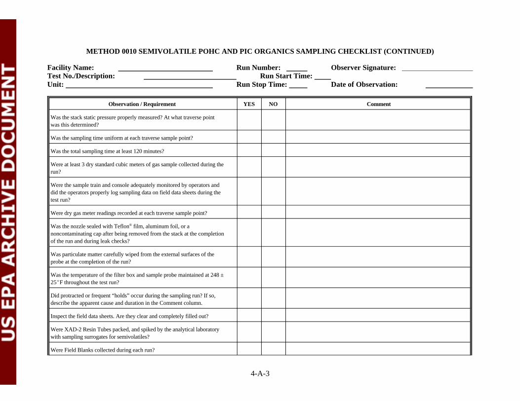
METHOD 0010 SEMIVOLATILE POHC AND PIC ORGANICS SAMPLING CHECKLIST (CONTINUED)
Facility Name: Run Number: Observer Signature: Test No./Description: Run Start Time: Unit: Run Stop Time: Date of Observation:
Observation / Requirement YES NO Comment
4-A-3
Was the stack static pressure properly measured? At what traverse pointwas this determined?
Was the sampling time uniform at each traverse sample point?
Was the total sampling time at least 120 minutes?
Were at least 3 dry standard cubic meters of gas sample collected during therun?
Were the sample train and console adequately monitored by operators anddid the operators properly log sampling data on field data sheets during thetest run?
Were dry gas meter readings recorded at each traverse sample point?
Was the nozzle sealed with Teflon film, aluminum foil, or a®
noncontaminating cap after being removed from the stack at the completionof the run and during leak checks?
Was particulate matter carefully wiped from the external surfaces of theprobe at the completion of the run?
Was the temperature of the filter box and sample probe maintained at 248 ±25EF throughout the test run?
Did protracted or frequent “holds” occur during the sampling run? If so,describe the apparent cause and duration in the Comment column.
Inspect the field data sheets. Are they clear and completely filled out?
Were XAD-2 Resin Tubes packed, and spiked by the analytical laboratorywith sampling surrogates for semivolatiles?
Were Field Blanks collected during each run?

METHOD 0010 SEMIVOLATILE POHC AND PIC ORGANICS SAMPLING CHECKLIST (CONTINUED)
Facility Name: Run Number: Observer Signature: Test No./Description: Run Start Time: Unit: Run Stop Time: Date of Observation:
Observation / Requirement YES NO Comment
4-A-4
Was the Blank Train set up identically to the acutal sampling trains andplaced on the stack or at the base of the stack for the duration of onecomplete sampling run? Was the Blank Train leak checked and heated totemperature throughout the run?
Were Reagent Blanks collected once during the three runs?
Were Trip Blanks collected once for each sample shipment?
Were spiked Resin Blanks prepared and analyzed before the trial burn?
GENERAL OBSERVATIONS AND COMMENTS

METHOD 0010 SEMIVOLATILE POHC AND PIC ORGANICS SAMPLING CHECKLIST (CONTINUED)
Facility Name: Run Number: Observer Signature: Test No./Description: Run Start Time: Unit: Run Stop Time: Date of Observation:
4-A-5
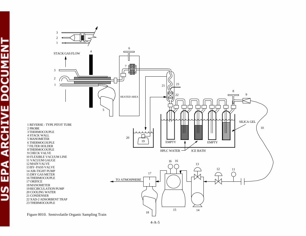
4-A-5
1 REVERSE - TYPE PITOT TUBE 2 PROBE 3 THERMOCOUPLE 4 STACK WALL 5 MANOMETER 6 THERMOCOUPLE 7 FILTER HOLDER 8 THERMOCOUPLE 9 CHECK VALVE10 FLEXIBLE VACUUM LINE11 VACUUM GAUGE12 MAIN VALVE13 BY- PASS VALVE14 AIR-TIGHT PUMP15 DRY GAS METER16 THERMOCOUPLE17 ORIFICE18 MANOMETER19 RECIRCULATION PUMP20 COOLING WATER21 CONDENSER22 XAD-2 ADSORBENT TRAP23 THERMOCOUPLE
Figure 0010. Semivolatile Organic Sampling Train
TO ATMOSPHERE
17
1815 14
16 1613
12 11
10
98
SILICA GEL
23
22
1920
21
HEATED AREA
6
7
5
4STACK GAS FLOW
3
2
1
3
2
1
ICE BATHHPLC WATER
EMPTYEMPTY

ATTACHMENT B
METHOD 0010 SEMIVOLATILE POHC AND PIC ORGANICSSAMPLE RECOVERY CHECKLIST
(5 Sheets)
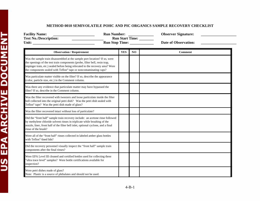
4-B-1
METHOD 0010 SEMIVOLATILE POHC AND PIC ORGANICS SAMPLE RECOVERY CHECKLIST
Facility Name: Run Number: Observer Signature: Test No./Description: Run Start Time: Unit: Run Stop Time: Date of Observation:
Observation / Requirement YES NO Comment
Was the sample train disassembled at the sample port location? If so, werethe openings of the test train components (probe, filter bell, resin trap,impinger train, etc.) sealed before being relocated to the recovery area? Werethe components sealed with Teflon tape or noncontaminating caps?®
Was particulate matter visible on the filter? If so, describe the appearance(color, particle size, etc.) in the Comment column.
Was there any evidence that particulate matter may have bypassed thefilter? If so, describe in the Comment column.
Was the filter recovered with tweezers and loose particulate inside the filterbell collected into the original petri dish? Was the petri dish sealed withTeflon tape? Was the petri dish made of glass?®
Was the filter recovered intact without loss of particulate?
Did the “front half” sample train recovery include: an acetone rinse followedby methylene chloride solvent rinses in triplicate while brushing of thenozzle, liner, front half of the filter bell inlet, optional cyclone, and a finalrinse of the brush?
Were all of the “front half” rinses collected in labeled amber glass bottleswith Teflon -lined lids?®
Did the recovery personnel visually inspect the “front half” sample traincomponents after the final rinses?
Were EPA Level III cleaned and certified bottles used for collecting these“ultra trace level” samples? Were bottle certifications available forinspection?
Were petri dishes made of glass? Note: Plastic is a source of phthalates and should not be used.

METHOD 0010 SEMIVOLATILE POHC AND PIC ORGANICS SAMPLE RECOVERY CHECKLIST (CONTINUED)
Facility Name: Run Number: Observer Signature: Test No./Description: Run Start Time: Unit: Run Stop Time: Date of Observation:
Observation / Requirement YES NO Comment
4-B-2
Were glass containers the narrow neck or Boston Round design instead of thewide mouth Packer Bottle design?
Were the openings of the resin trap sealed with tight fittingnoncontaminating plugs or caps? Was the resin trap wrapped withaluminum foil and properly labeled?
Were the contents of the knockout impingers and deionized water impingersrecovered into an amber glass bottle with a Teflon -lined lid?®
Were the knockout impingers and the deionized water impingers rinsed threetimes with deionized water followed by methylene chloride?
Was the moisture gain of each impinger recorded before recovery of thecontents was commenced?
Was the impinger composite and deionized water rinse volume recordedseparately than the moisture gain in the impingers?
Did the “back half” sample train recovery include triplicate acetone followedby methylene chloride rinses of the back half of the filter bell outlet, filtersupport, coil condenser, and interconnecting glassware?
Were the contents of the back half sample collected into an amber glassbottle with a Teflon -lined lid? ®
At the conclusion of the sample train recovery, were the openings of thesample train components sealed with Teflon tape or noncontaminating®
caps?
Was the condensate in the impingers collected for this test program inaccordance with the approved trial burn plan?
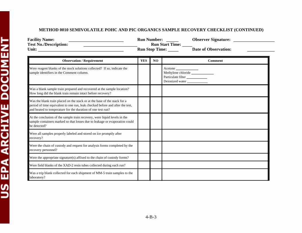
METHOD 0010 SEMIVOLATILE POHC AND PIC ORGANICS SAMPLE RECOVERY CHECKLIST (CONTINUED)
Facility Name: Run Number: Observer Signature: Test No./Description: Run Start Time: Unit: Run Stop Time: Date of Observation:
Observation / Requirement YES NO Comment
4-B-3
Were reagent blanks of the stock solutions collected? If so, indicate the Acetone sample identifiers in the Comment column. Methylene chloride
Particulate filter Deionized water
Was a blank sample train prepared and recovered at the sample location? How long did the blank train remain intact before recovery?
Was the blank train placed on the stack or at the base of the stack for aperiod of time equivalent to one run, leak checked before and after the test,and heated to temperature for the duration of one test run?
At the conclusion of the sample train recovery, were liquid levels in thesample containers marked so that losses due to leakage or evaporation couldbe detected?
Were all samples properly labeled and stored on ice promptly afterrecovery?
Were the chain of custody and request for analysis forms completed by therecovery personnel?
Were the appropriate signature(s) affixed to the chain of custody forms?
Were field blanks of the XAD-2 resin tubes collected during each run?
Was a trip blank collected for each shipment of MM-5 train samples to thelaboratory?

METHOD 0010 SEMIVOLATILE POHC AND PIC ORGANICS SAMPLE RECOVERY CHECKLIST (CONTINUED)
Facility Name: Run Number: Observer Signature: Test No./Description: Run Start Time: Unit: Run Stop Time: Date of Observation:
Observation / Requirement YES NO Comment
4-B-4
Was a tracking system and labeling of samples conducted in such a way as toassist the laboratory in processing as separate samples the following traincomponents:(1) The particulate filter, and the front half of the filter holder, nozzle andprobe acetone, methylene chloride solvent rinses(2) The XAD-2 resin tube and the back half of the filter holder, coilcondenser, and connecting glassware acetone, methylene chloride solventrinses(3) Knockout impinger and deionized water impinger composite withdeionized water and methylene chloride rinses.
Was a tracking and labeling system used which was clearly understood bythe observer and would this system be clear to the receiving laboratory?
Was the recovery facility kept clean at all times?

METHOD 0010 SEMIVOLATILE POHC AND PIC ORGANICS SAMPLE RECOVERY CHECKLIST (CONTINUED)
Facility Name: Run Number: Observer Signature: Test No./Description: Run Start Time: Unit: Run Stop Time: Date of Observation:
4-B-5
GENERAL OBSERVATIONS AND COMMENTS

ATTACHMENT C
METHOD 0012 MULTIPLE METALS SAMPLING CHECKLIST
(5 Sheets)

METHOD 0012 MULTIPLE METALS SAMPLING CHECKLIST
Facility Name: Unit: Observer: Test No. / Description: Run No.: Date: Run Start Time: Run Stop Time:
4-C-1
Observation / Requirement YES NO Comment
Did the train components appear to be clean and were all glassware openingscovered with Teflon film before the train was assembled?®
Was the acidic potassium permanganate absorbing solution made fresh on thetest day and stored in an amber glass container with a Teflon lined cap?®
Was the train assembled by personnel in a manner that minimizedcontamination potential?
Was the train constructed of the components and materials identified inMethod 0012 (See Figure 0012: nozzle, heated probe, filter holder, 4-7impingers in ice bath, control console, etc.)?
Was the nozzle and probe liner constructed of glass or quartz?
Was the dry gas meter, thermocouples, nozzle, and critical orifice devices Dry gas metercalibrated prior to the test? If yes, provide the calibration date in the ThermocouplesComment column. If available, attach a copy of the calibration records. Critical orifice
Nozzle
Were weather conditions adverse to sampling (rain, snow, etc.)? If so,describe the measures taken to protect the sampling equipment in theComment column.
Was the sampling area (i.e., platform) kept clean and orderly during the run?
Were the traverse sample points determined in accordance with Method 1?
Was a cyclonic flow check made before the start of testing? If yes, record thedate and time the check was completed in the Comment column.
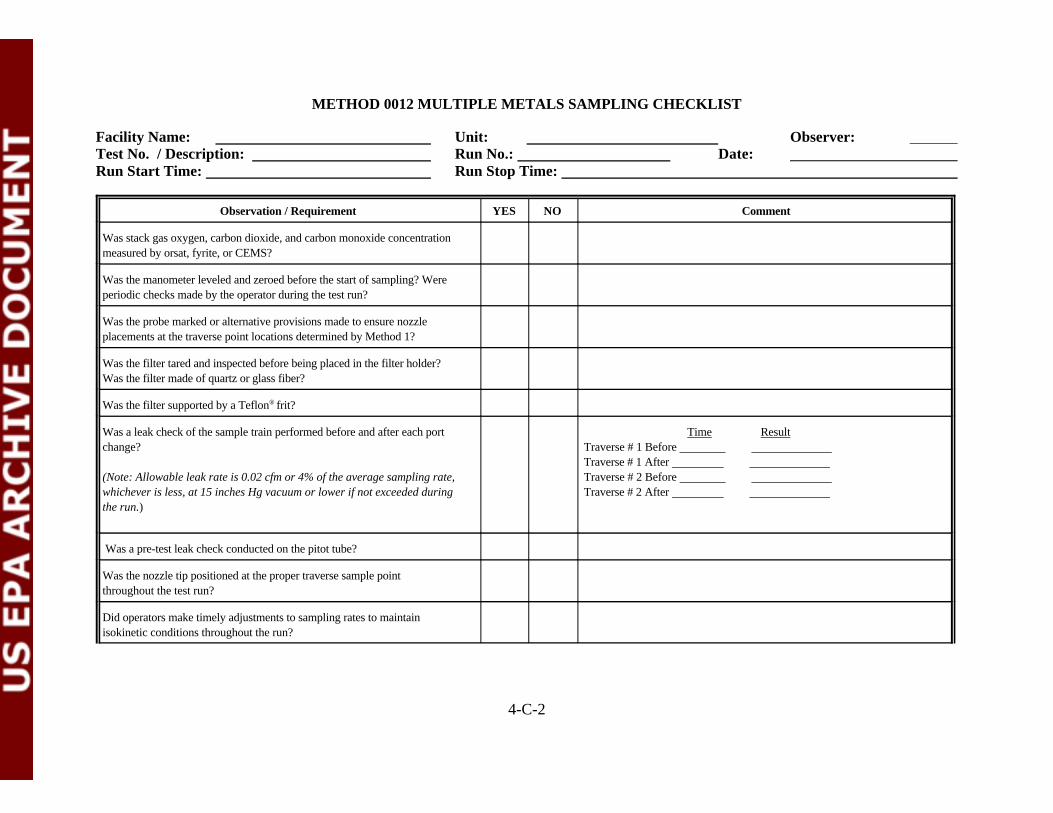
METHOD 0012 MULTIPLE METALS SAMPLING CHECKLIST
Facility Name: Unit: Observer: Test No. / Description: Run No.: Date: Run Start Time: Run Stop Time:
Observation / Requirement YES NO Comment
4-C-2
Was stack gas oxygen, carbon dioxide, and carbon monoxide concentrationmeasured by orsat, fyrite, or CEMS?
Was the manometer leveled and zeroed before the start of sampling? Wereperiodic checks made by the operator during the test run?
Was the probe marked or alternative provisions made to ensure nozzleplacements at the traverse point locations determined by Method 1?
Was the filter tared and inspected before being placed in the filter holder?Was the filter made of quartz or glass fiber?
Was the filter supported by a Teflon frit?®
Was a leak check of the sample train performed before and after each port Time Resultchange? Traverse # 1 Before
(Note: Allowable leak rate is 0.02 cfm or 4% of the average sampling rate, Traverse # 2 Before whichever is less, at 15 inches Hg vacuum or lower if not exceeded during Traverse # 2 After the run.)
Traverse # 1 After
Was a pre-test leak check conducted on the pitot tube?
Was the nozzle tip positioned at the proper traverse sample pointthroughout the test run?
Did operators make timely adjustments to sampling rates to maintainisokinetic conditions throughout the run?
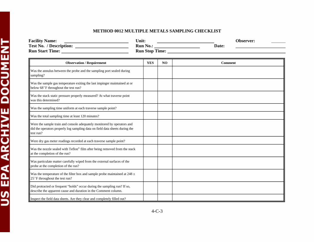
METHOD 0012 MULTIPLE METALS SAMPLING CHECKLIST
Facility Name: Unit: Observer: Test No. / Description: Run No.: Date: Run Start Time: Run Stop Time:
Observation / Requirement YES NO Comment
4-C-3
Was the annulus between the probe and the sampling port sealed duringsampling?
Was the sample gas temperature exiting the last impinger maintained at orbelow 68EF throughout the test run?
Was the stack static pressure properly measured? At what traverse pointwas this determined?
Was the sampling time uniform at each traverse sample point?
Was the total sampling time at least 120 minutes?
Were the sample train and console adequately monitored by operators anddid the operators properly log sampling data on field data sheets during thetest run?
Were dry gas meter readings recorded at each traverse sample point?
Was the nozzle sealed with Teflon film after being removed from the stack®
at the completion of the run?
Was particulate matter carefully wiped from the external surfaces of theprobe at the completion of the run?
Was the temperature of the filter box and sample probe maintained at 248 ±25EF throughout the test run?
Did protracted or frequent “holds” occur during the sampling run? If so,describe the apparent cause and duration in the Comment column.
Inspect the field data sheets. Are they clear and completely filled out?

METHOD 0012 MULTIPLE METALS SAMPLING CHECKLIST
Facility Name: Unit: Observer: Test No. / Description: Run No.: Date: Run Start Time: Run Stop Time:
4-C-4

METHOD 0012 MULTIPLE METALS SAMPLING CHECKLIST
Facility Name: Unit: Observer: Test No. / Description: Run No.: Date: Run Start Time: Run Stop Time:
4-C-5
GENERAL OBSERVATIONS AND COMMENTS

1 REVERSE - TYPE PITOT TUBE 2 GLASS PROBE 3 THERMOCOUPLE 4 STACK WALL 5 MANOMETER 6 THERMOCOUPLE 7 FILTER HOLDER 8 THERMOCOUPLE 9 CHECK VALVE10 FLEXIBLE VACUUM LINE11 VACUUM GAUGE12 MAIN VALVE13 BY- PASS VALVE14 AIR-TIGHT PUMP15 DRY GAS METER16 THERMOCOUPLE17 ORIFICE18 MANOMETER
4-C-5
TO ATMOSPHERE
17
18 15 14
16 1613
12 11
10
98
SILICA GEL
HEATED AREA
6
7
5
4STACK GAS FLOW
3
2
1
3
2
1
5% HNO3/10% H2O2 4% KMnO4/10% H2SO4
ICE BATH
EMPTY EMPTY
Figure 0012. Multiple Metals Sampling Train

ATTACHMENT D
METHOD 0012 MULTIPLE METALS SAMPLE RECOVERY CHECKLIST
(4 Sheets)
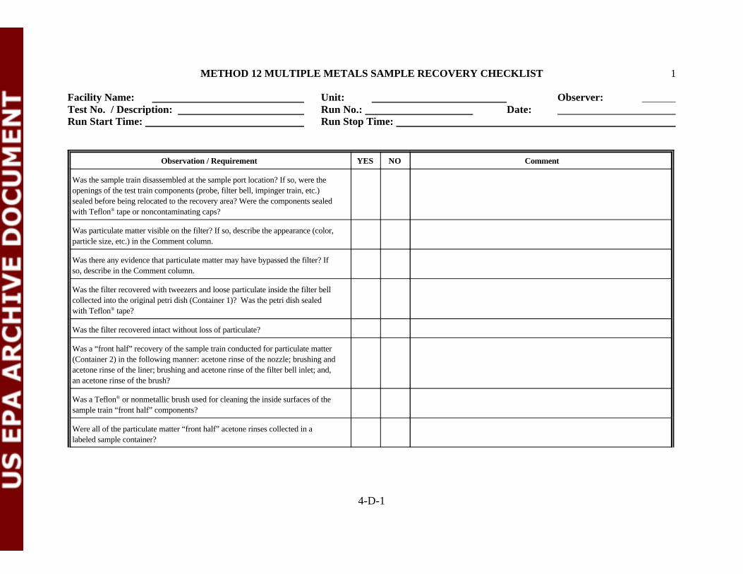
METHOD 12 MULTIPLE METALS SAMPLE RECOVERY CHECKLIST 1
Facility Name: Unit: Observer: Test No. / Description: Run No.: Date: Run Start Time: Run Stop Time:
4-D-1
Observation / Requirement YES NO Comment
Was the sample train disassembled at the sample port location? If so, were theopenings of the test train components (probe, filter bell, impinger train, etc.)sealed before being relocated to the recovery area? Were the components sealedwith Teflon tape or noncontaminating caps?®
Was particulate matter visible on the filter? If so, describe the appearance (color,particle size, etc.) in the Comment column.
Was there any evidence that particulate matter may have bypassed the filter? Ifso, describe in the Comment column.
Was the filter recovered with tweezers and loose particulate inside the filter bellcollected into the original petri dish (Container 1)? Was the petri dish sealedwith Teflon tape?®
Was the filter recovered intact without loss of particulate?
Was a “front half” recovery of the sample train conducted for particulate matter(Container 2) in the following manner: acetone rinse of the nozzle; brushing andacetone rinse of the liner; brushing and acetone rinse of the filter bell inlet; and,an acetone rinse of the brush?
Was a Teflon or nonmetallic brush used for cleaning the inside surfaces of the®
sample train “front half” components?
Were all of the particulate matter “front half” acetone rinses collected in alabeled sample container?

METHOD 12 MULTIPLE METALS SAMPLE RECOVERY CHECKLIST 2
Facility Name: Unit: Observer: Test No. / Description: Run No.: Date: Run Start Time: Run Stop Time:
Observation / Requirement YES NO Comment
4-D-2
Was a “front half” recovery of the sample train conducted for metals (Container3) in the following manner: rinse of nozzle, liner, and filter bell inlet with 100mL of 0.1 N nitric acid?
Were all of the metals “front half” rinses collected into the same prelabeledcontainer?
Was a final nonsample rinse of the “front half” sample train componentsconducted with deionized water and acetone? Were the openings sealed withTeflon tape or noncontaminating caps?®
Were the impingers weighed or measured for moisture content determinationbefore recovery of the solution contents?
Were the liquid contents of impingers 1, 2, and 3 collected in a prelabeledsample bottle (Container 4)?
Was the filter holder outlet inspected for condensate and, if condensate waspresent, was it added to Container 4 ?
Was the filter holder outlet, the filter support, impingers 1-3, and all connectingglassware rinsed with 100 mL of 0.1N nitric acid and added to Container 4?
Was the liquid contents in impinger 4 collected in an amber glass sample bottlewith a Teflon -lined lid (Container 5a)?®
Was impinger 4 rinsed with 100 mL of 0.1N nitric acid and added to Container5a?
Were the liquid contents of impingers 5 and 6 collected in an amber glass bottlewith a Teflon -lined lid (Container 5b)?®

METHOD 12 MULTIPLE METALS SAMPLE RECOVERY CHECKLIST 3
Facility Name: Unit: Observer: Test No. / Description: Run No.: Date: Run Start Time: Run Stop Time:
Observation / Requirement YES NO Comment
4-D-3
Were impingers 5 and 6 and connecting glassware triple rinsed with 100 mL ofthe acidified potassium permanganate solution and the rinsate added toContainer 5b?
Were impingers 5 and 6 and connecting glassware triple rinsed with 100 mL ofdeionized water and the rinsate added to Container 5b?
Did the recovery personnel visually inspect impingers 5 and 6 for residuedeposits following the deionized water rinse?
If residue deposits remained in impingers 5 and 6, were they rinsed with 25 mLof 8N hydrogen chloride and collected into an amber glass bottle with a Teflon -®
lined cap containing 200 mL deionized water (Container 5c)?
Was the silica gel impinger weighed to the nearest 0.5g?
At the conclusion of the sample train recovery, were the openings of the sampletrain components sealed with Teflon tape or noncontaminating caps?®
Were reagent blanks of the stock solutions collected according to the sampling Acetone___________________________________________plan? If so, indicate the sample identifiers in the Comment column Deionized Water___________________________________
0.1 N HNO _________________________________________3
HNO /H O __________________________________________3 2 2
H SO /KMnO ________________________________________2 4 4
8N HCl____________________________________________Filters (3)_______________________________________
Was a blank sample train prepared and recovered at the sample location? Howlong did the blank train remain intact before recovery?
Were all samples properly labeled and stored on ice promptly after recovery?

METHOD 12 MULTIPLE METALS SAMPLE RECOVERY CHECKLIST 4
Facility Name: Unit: Observer: Test No. / Description: Run No.: Date: Run Start Time: Run Stop Time:
Observation / Requirement YES NO Comment
4-D-4
Were the chain of custody and request for analysis forms completed by therecovery personnel ?
Were the appropriate signature(s) affixed to the chain of custody forms?
GENERAL OBSERVATIONS AND COMMENTS

ATTACHMENT E
METHOD 0013 HEXAVALENT CHROMIUM SAMPLING CHECKLIST
(4 Sheets)
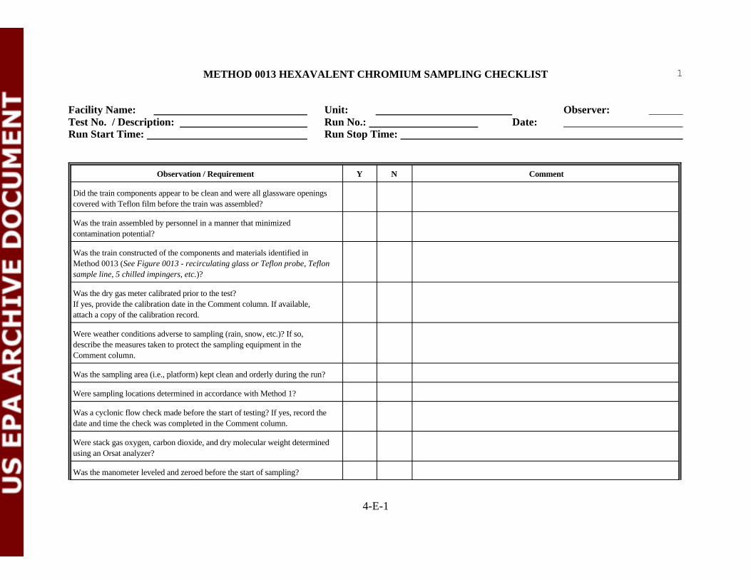
METHOD 0013 HEXAVALENT CHROMIUM SAMPLING CHECKLIST
Facility Name: Unit: Observer: Test No. / Description: Run No.: Date: Run Start Time: Run Stop Time:
1
4-E-1
Observation / Requirement Y N Comment
Did the train components appear to be clean and were all glassware openingscovered with Teflon film before the train was assembled?
Was the train assembled by personnel in a manner that minimizedcontamination potential?
Was the train constructed of the components and materials identified inMethod 0013 (See Figure 0013 - recirculating glass or Teflon probe, Teflonsample line, 5 chilled impingers, etc.)?
Was the dry gas meter calibrated prior to the test?If yes, provide the calibration date in the Comment column. If available,attach a copy of the calibration record.
Were weather conditions adverse to sampling (rain, snow, etc.)? If so,describe the measures taken to protect the sampling equipment in theComment column.
Was the sampling area (i.e., platform) kept clean and orderly during the run?
Were sampling locations determined in accordance with Method 1?
Was a cyclonic flow check made before the start of testing? If yes, record thedate and time the check was completed in the Comment column.
Were stack gas oxygen, carbon dioxide, and dry molecular weight determinedusing an Orsat analyzer?
Was the manometer leveled and zeroed before the start of sampling?

METHOD 0013 HEXAVALENT CHROMIUM SAMPLING CHECKLIST
Facility Name: Unit: Observer: Test No. / Description: Run No.: Date: Run Start Time: Run Stop Time:
2
Observation / Requirement Y N Comment
4-E-2
Was the probe marked or alternative provisions made to ensure nozzleplacements at the points identified by Method 1?
Was a pre-test leak check performed?
Was a leak check performed before and after each port change? Note: Time ResultAllowable leak rate is 0.02 cfm or 4% of the average sampling rate, Traverse # 1 Before whichever is less, at 15 inches Hg vacuum or lower if not exceeded during Traverse # 1 After the run. Traverse # 2 Before
Traverse # 2 After
Was the probe consistently repositioned at the proper time and to theproper sampling point throughout the run?
Did operators make timely adjustments to sampling rates to maintainisokinetic conditions throughout the run?
Was the annulus between the probe and the sampling port sealed duringsampling?
Was the absorbing liquid from the first impinger continuously recirculatedthrough the sample line during the run?
Was the probe maintained at a temperature below 200 EF throughoutsampling to prevent the boiling of the recirculating liquid?
Was the stack static pressure properly measured?
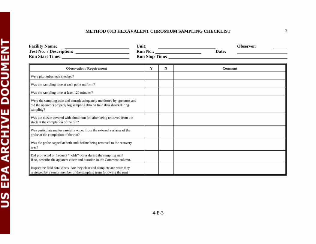
METHOD 0013 HEXAVALENT CHROMIUM SAMPLING CHECKLIST
Facility Name: Unit: Observer: Test No. / Description: Run No.: Date: Run Start Time: Run Stop Time:
3
Observation / Requirement Y N Comment
4-E-3
Were pitot tubes leak checked?
Was the sampling time at each point uniform?
Was the sampling time at least 120 minutes?
Were the sampling train and console adequately monitored by operators anddid the operators properly log sampling data on field data sheets duringsampling?
Was the nozzle covered with aluminum foil after being removed from thestack at the completion of the run?
Was particulate matter carefully wiped from the external surfaces of theprobe at the completion of the run?
Was the probe capped at both ends before being removed to the recoveryarea?
Did protracted or frequent “holds” occur during the sampling run?If so, describe the apparent cause and duration in the Comment column.
Inspect the field data sheets. Are they clear and complete and were theyreviewed by a senior member of the sampling team following the run?

METHOD 0013 HEXAVALENT CHROMIUM SAMPLING CHECKLIST
Facility Name: Unit: Observer: Test No. / Description: Run No.: Date: Run Start Time: Run Stop Time:
4
4-E-4
GENERAL OBSERVATIONS AND COMMENTS
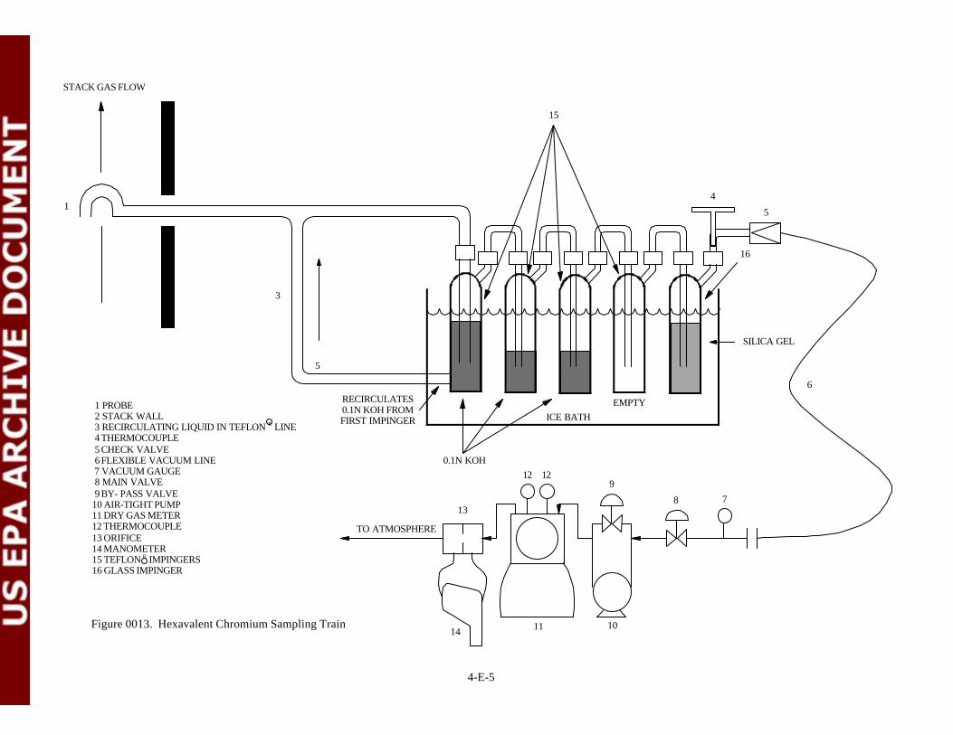
4-E-5
1 PROBE 2 STACK WALL 3 RECIRCULATING LIQUID IN TEFLON R LINE 4 THERMOCOUPLE 5 CHECK VALVE 6 FLEXIBLE VACUUM LINE 7 VACUUM GAUGE 8 MAIN VALVE 9 BY- PASS VALVE10 AIR-TIGHT PUMP11 DRY GAS METER12 THERMOCOUPLE13 ORIFICE14 MANOMETER15 TEFLON R IMPINGERS16 GLASS IMPINGER
Figure 0013. Hexavalent Chromium Sampling Train
TO ATMOSPHERE
14 11 10
12 129
8 7
6
5
4
SILICA GEL
5
STACK GAS FLOW
1
3
0.1N KOH
ICE BATH
13
EMPTYRECIRCULATES0.1N KOH FROMFIRST IMPINGER
15
16

ATTACHMENT F
METHOD 0013 HEXAVALENT CHROMIUM SAMPLE RECOVERY CHECKLIST
(2 Sheets)

METHOD 0013 HEXAVALENT CHROMIUM SAMPLE RECOVERY CHECKLIST
Facility Name: Unit: Observer: Test No. / Description: Run No.: Date: Run Start Time: Run Stop Time:
1
4-F-1
Observation / Requirement Y N Comment
Was the train disassembled in a clean area in a manner that minimized thepotential for sample loss and/or contamination?
Was the pH of impinger 1 checked and determined to be greater than 8.5?
Was nitrogen bubbled through the impinger train at approximately 10 litersper minute for 30 minutes?
Were the liquid contents of impingers 1, 2, 3, and 4 measured or weighed,and recorded on the recovery data sheets?
Were the liquid contents of impingers 1, 2, 3, and 4 placed in an amber glasssample bottle (Container 1)?
Were the nozzle, probe, recirculating sample line, and first four impingersrinsed four times with distilled deionized water and were the rinses added toContainer 1?
Were the “back half” of the filter holder, the filter support, and allconnecting glassware rinsed with 100 mL of 0.1N nitric acid and were therinses added to Container 3?
Were the contents of Container 3 filtered to remove insoluble matter?
Was Container 3 rinsed 3 times with distilled deionized water and was therinse solution filtered?
Were the filter and reservoir rinsed 3 times and were these rinses filtered?
Was the silica gel impinger weighed to the nearest 0.5g?
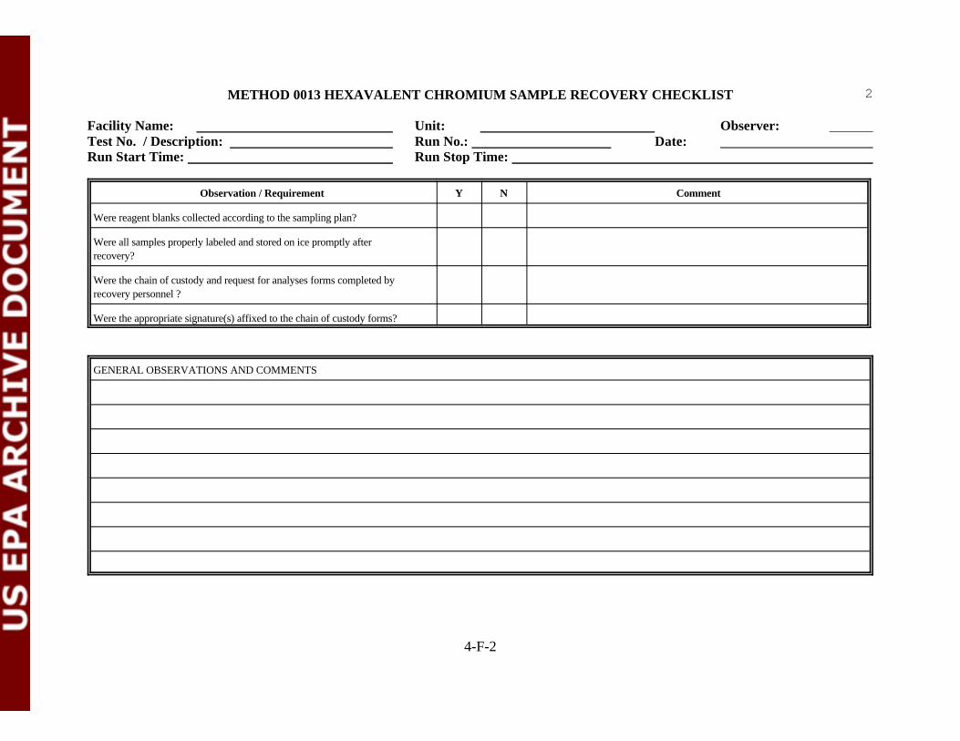
METHOD 0013 HEXAVALENT CHROMIUM SAMPLE RECOVERY CHECKLIST
Facility Name: Unit: Observer: Test No. / Description: Run No.: Date: Run Start Time: Run Stop Time:
2
Observation / Requirement Y N Comment
4-F-2
Were reagent blanks collected according to the sampling plan?
Were all samples properly labeled and stored on ice promptly afterrecovery?
Were the chain of custody and request for analyses forms completed byrecovery personnel ?
Were the appropriate signature(s) affixed to the chain of custody forms?
GENERAL OBSERVATIONS AND COMMENTS

ATTACHMENT G
METHOD 23 PCDD/PCDF SAMPLING CHECKLIST
(6 Sheets)
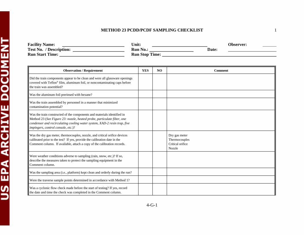
METHOD 23 PCDD/PCDF SAMPLING CHECKLIST 1
Facility Name: Unit: Observer: Test No. / Description: Run No.: Date: Run Start Time: Run Stop Time:
4-G-1
Observation / Requirement YES NO Comment
Did the train components appear to be clean and were all glassware openingscovered with Teflon film, aluminum foil, or noncontaminating caps before®
the train was assembled?
Was the aluminum foil prerinsed with hexane?
Was the train assembled by personnel in a manner that minimizedcontamination potential?
Was the train constructed of the components and materials identified inMethod 23 (See Figure 23: nozzle, heated probe, particulate filter, onecondenser and recirculating cooling water system, XAD-2 resin trap, fiveimpingers, control console, etc.)?
Was the dry gas meter, thermocouples, nozzle, and critical orifice devices Dry gas metercalibrated prior to the test? If yes, provide the calibration date in the ThermocouplesComment column. If available, attach a copy of the calibration records. Critical orifice
Nozzle
Were weather conditions adverse to sampling (rain, snow, etc.)? If so,describe the measures taken to protect the sampling equipment in theComment column.
Was the sampling area (i.e., platform) kept clean and orderly during the run?
Were the traverse sample points determined in accordance with Method 1?
Was a cyclonic flow check made before the start of testing? If yes, recordthe date and time the check was completed in the Comment column.

METHOD 23 PCDD/PCDF SAMPLING CHECKLIST 2
Facility Name: Unit: Observer: Test No. / Description: Run No.: Date: Run Start Time: Run Stop Time:
Observation / Requirement YES NO Comment
4-G-2
Was stack gas oxygen, carbon dioxide, and carbon monoxide concentrationmeasured by orsat, fyrite, or CEMS?
Was the manometer leveled and zeroed before the start of sampling? Wereperiodic checks made by the operator during the test run?
Was the probe marked or alternative provisions made to ensure nozzleplacements at the traverse point locations determined by Method 1?
Was the XAD-2 resin prepared within the last four weeks? Indicate thepreparation date in the Comment column.
Was the resin trap covered with aluminum foil and the openings sealed withglass stoppers?
Was high-performance liquid chromatography grade water used for in theimpingers?
Was the filter tared and inspected before being placed in the filter holder?Was the filter made of glass fiber?
Was the filter supported with a Teflon frit or Teflon -coated wire?® ®
Was a leak check of the sample train performed before and after each port Time Resultchange? Traverse # 1 Before
(Note: Allowable leak rate is 0.02 cfm or 4% of the average sampling rate, Traverse # 2 Before whichever is less, at 15 inches Hg vacuum or lower if not exceeded during Traverse # 2 After the run.)
Traverse # 1 After

METHOD 23 PCDD/PCDF SAMPLING CHECKLIST 3
Facility Name: Unit: Observer: Test No. / Description: Run No.: Date: Run Start Time: Run Stop Time:
Observation / Requirement YES NO Comment
4-G-3
Were pre-test and post-test leak checks conducted on the pitot tube?
Was silicone grease used on any connections of the sample train?
Was the nozzle tip positioned at the proper traverse sample pointthroughout the test run?
Did operators make timely adjustments to sampling rates to maintainisokinetic conditions throughout the run?
Was the annulus between the probe and the sampling port sealed duringsampling?
Was the sample gas temperature entering the resin trap maintained at orbelow 68EF throughout the test run?
Was the sample gas temperature exiting the last impinger maintained at orbelow 68EF throughout the test run?
Was the stack static pressure properly measured? At what traverse pointwas this determined?
Was the sampling time uniform at each traverse sample point?
Was the total sampling time at least 120 minutes?
Were at least 3 dry standard cubic meters of gas sample collected during therun?
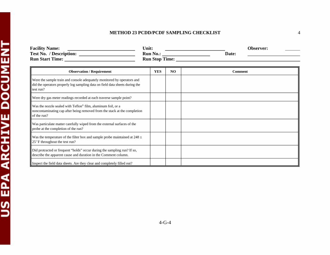
METHOD 23 PCDD/PCDF SAMPLING CHECKLIST 4
Facility Name: Unit: Observer: Test No. / Description: Run No.: Date: Run Start Time: Run Stop Time:
Observation / Requirement YES NO Comment
4-G-4
Were the sample train and console adequately monitored by operators anddid the operators properly log sampling data on field data sheets during thetest run?
Were dry gas meter readings recorded at each traverse sample point?
Was the nozzle sealed with Teflon film, aluminum foil, or a®
noncontaminating cap after being removed from the stack at the completionof the run?
Was particulate matter carefully wiped from the external surfaces of theprobe at the completion of the run?
Was the temperature of the filter box and sample probe maintained at 248 ±25EF throughout the test run?
Did protracted or frequent “holds” occur during the sampling run? If so,describe the apparent cause and duration in the Comment column.
Inspect the field data sheets. Are they clear and completely filled out?

METHOD 23 PCDD/PCDF SAMPLING CHECKLIST 5
Facility Name: Unit: Observer: Test No. / Description: Run No.: Date: Run Start Time: Run Stop Time:
4-G-5
GENERAL OBSERVATIONS AND COMMENTS

4-G-6
1 REVERSE - TYPE PITOT TUBE 2 PROBE 3 THERMOCOUPLE 4 STACK WALL 5 MANOMETER 6 THERMOCOUPLE 7 FILTER HOLDER 8 THERMOCOUPLE 9 CHECK VALVE10 FLEXIBLE VACUUM LINE11 VACUUM GAUGE12 MAIN VALVE13 BY- PASS VALVE14 AIR-TIGHT PUMP15 DRY GAS METER16 THERMOCOUPLE17 ORIFICE18 MANOMETER19 RECIRCULATION PUMP20 COOLING WATER21 CONDENSER22 XAD-2 ADSORBENT TRAP23 THERMOCOUPLE
Figure 0023. PCDD/PCDF Sampling Train
TO ATMOSPHERE
17
1815 14
16 1613
12 11
10
98
SILICA GEL
23
22
1920
21
HEATED AREA
6
7
5
4STACK GAS FLOW
3
2
1
3
2
1
ICE BATHHPLC WATER
EMPTYEMPTY

ATTACHMENT H
METHOD 23 PCDD/PCDF SAMPLE RECOVERY CHECKLIST
(4 Sheets)
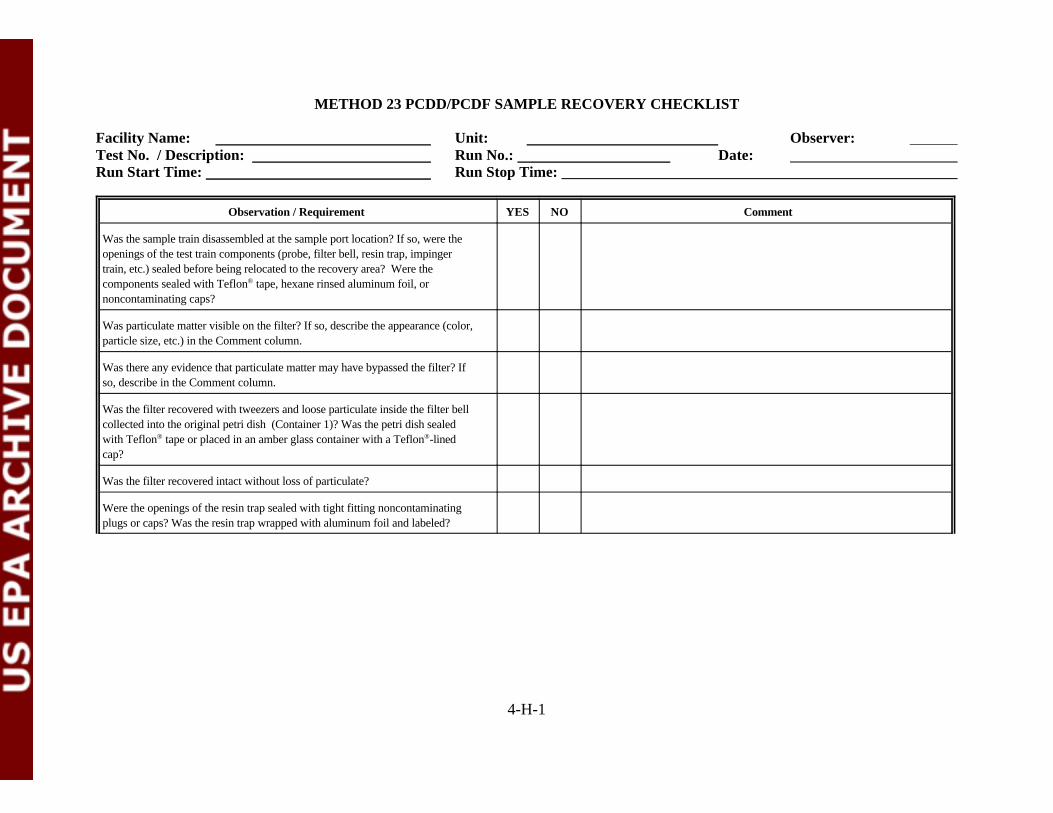
4-H-1
METHOD 23 PCDD/PCDF SAMPLE RECOVERY CHECKLIST
Facility Name: Unit: Observer: Test No. / Description: Run No.: Date: Run Start Time: Run Stop Time:
Observation / Requirement YES NO Comment
Was the sample train disassembled at the sample port location? If so, were theopenings of the test train components (probe, filter bell, resin trap, impingertrain, etc.) sealed before being relocated to the recovery area? Were thecomponents sealed with Teflon tape, hexane rinsed aluminum foil, or®
noncontaminating caps?
Was particulate matter visible on the filter? If so, describe the appearance (color,particle size, etc.) in the Comment column.
Was there any evidence that particulate matter may have bypassed the filter? Ifso, describe in the Comment column.
Was the filter recovered with tweezers and loose particulate inside the filter bellcollected into the original petri dish (Container 1)? Was the petri dish sealedwith Teflon tape or placed in an amber glass container with a Teflon -lined® ®
cap?
Was the filter recovered intact without loss of particulate?
Were the openings of the resin trap sealed with tight fitting noncontaminatingplugs or caps? Was the resin trap wrapped with aluminum foil and labeled?
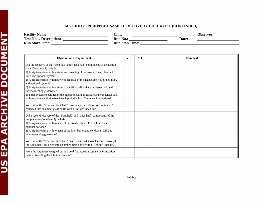
METHOD 23 PCDD/PCDF SAMPLE RECOVERY CHECKLIST (CONTINUED)
Facility Name: Unit: Observer: Test No. / Description: Run No.: Date: Run Start Time: Run Stop Time:
Observation / Requirement YES NO Comment
4-H-2
Did the recovery of the “front half” and “back half” components of the sampletrain (Container 2) include:1) A triplicate rinse with acetone and brushing of the nozzle, liner, filter bellinlet, and optional cyclone?2) A triplicate rinse with methylene chloride of the nozzle, liner, filter bell inlet,and optional cyclone?3) A triplicate rinse with acetone of the filter bell outlet, condenser coil, andinterconnecting glassware?4) Three separate soakings of the interconnecting glassware and condenser coilwith methylene chloride (each soak period at least 5 minutes in duration)?
Were all of the “front and back half” rinses identified above for Container 2collected into an amber glass bottle with a Teflon -lined lid?®
Did a second recovery of the “front half” and “back half” components of thesample train (Container 3) include:1) A triplicate rinse with toluene of the nozzle, liner, filter bell inlet, andoptional cyclone?2) A triplicate rinse with toluene of the filter bell outlet, condenser coil, andinterconnecting glassware?
Were all of the “front and back half” rinses identified above (second recovery)for Container 3 collected into an amber glass bottle with a Teflon -lined lid?®
Were the impingers weighed or measured for moisture content determinationbefore discarding the solution contents?

METHOD 23 PCDD/PCDF SAMPLE RECOVERY CHECKLIST (CONTINUED)
Facility Name: Unit: Observer: Test No. / Description: Run No.: Date: Run Start Time: Run Stop Time:
Observation / Requirement YES NO Comment
4-H-3
At the conclusion of the sample train recovery, were the openings of the sampletrain components sealed with Teflon tape, hexane rinsed aluminum foil, or®
noncontaminating caps?
Was the condensate in the impingers collected for this test program inaccordance with the sampling plan?
Were high-performance liquid chromatography grade acetone, methylenechloride, and toluene used during the recovery?
Were reagent blanks of the stock rinsate solutions collected according to the methylene chloride ________________________________sampling plan? If so, indicate the sample I.D. names in the Comment column acetone___________________________________________
toluene___________________________________________
Was a blank sample train prepared and recovered at the sample location? Howlong did the blank train remain intact before recovery?
Were all samples properly labeled and stored on ice promptly after recovery?
Were the chain of custody and request for analysis forms completed by therecovery personnel?
Were the appropriate signature(s) affixed to the chain of custody forms?

METHOD 23 PCDD/PCDF SAMPLE RECOVERY CHECKLIST (CONTINUED)
Facility Name: Unit: Observer: Test No. / Description: Run No.: Date: Run Start Time: Run Stop Time:
4-H-4
GENERAL OBSERVATIONS AND COMMENTS

ATTACHMENT I
METHOD 0030 VOLATILE ORGANICS SAMPLING TRAIN CHECKLIST
(4 Sheets)

METHOD 0030 VOLATILE ORGANICS SAMPLING TRAIN CHECKLIST 1
Facility Name: Unit: Observer: Test No. / Description: Run No.: Date: Run Start Time: Run Stop Time:
4-I-1
Observation / Requirement YES NO Comment
Did the train components appear to be clean and were all glassware openingscovered with Teflon film or noncontaminating caps before the train was®
assembled?
Was the train assembled by personnel in a manner that minimizedcontamination potential?
Were the adsorbent tube cartridges stored on ice before use?
Was the train constructed of the components and materials identified inMethod 0030 (See Figure 0030: probe, valve, Tenax cartridge, condenser,condensate impinger, condenser, Tenax/charcoal cartridge, silica gelimpinger, etc.)?
Were the dry gas meter, thermocouples, and rotameter devices calibrated Dry gas meterprior to the test? If yes, provide the calibration dates in the Comment Thermocouplescolumn. If available, attach a copy of the calibration records. Rotameter
Were weather conditions adverse to sampling (rain, snow, etc.)? If so,describe the measures taken to protect the sampling equipment in theComment column.
Was the sampling area (i.e., platform) kept clean and orderly during the run?
Were pre-test and post-test leak checks of the sample train conducted?(Note: Pre-test leak check should be <2.5 mm Hg over 1 minute. Post-testleak check should be <2.5 mm Hg over 1 minute at the highest sample trainvacuum encountered during the test period)
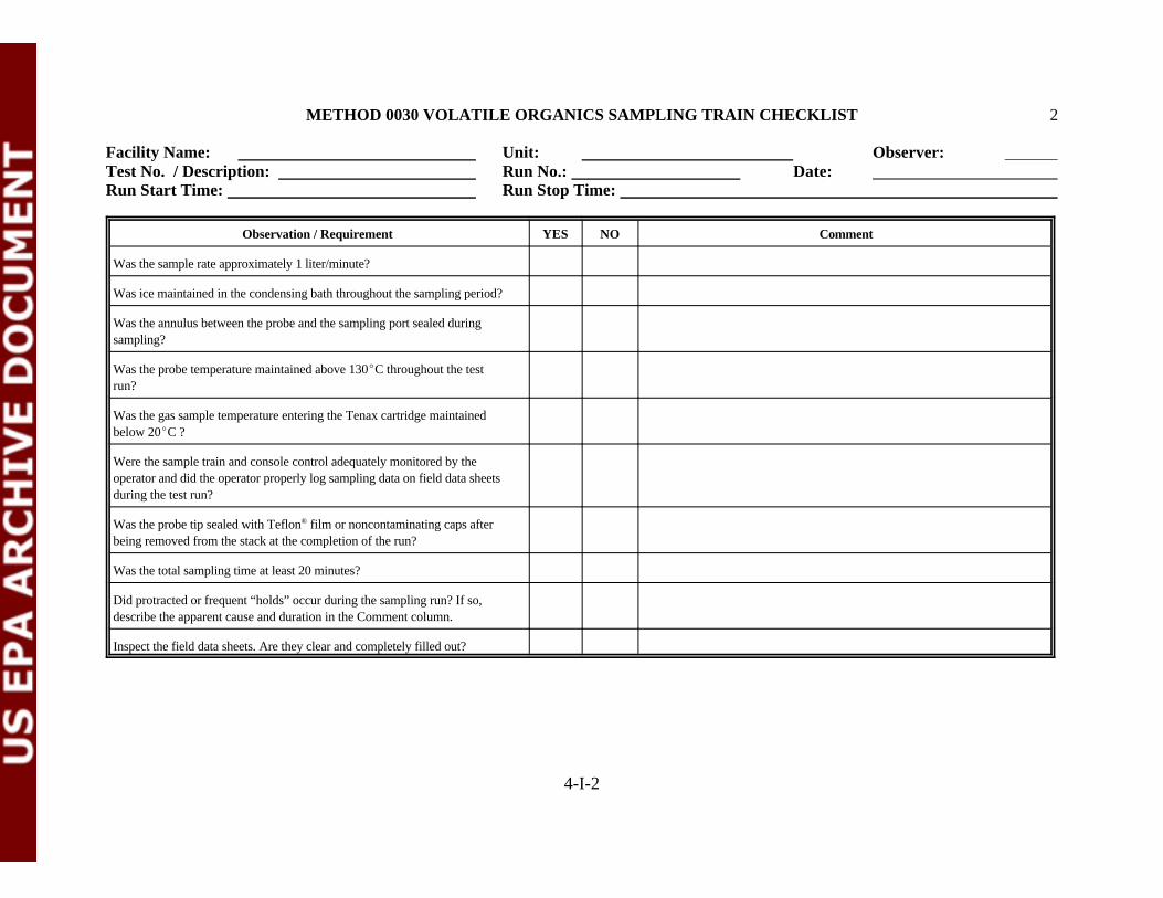
METHOD 0030 VOLATILE ORGANICS SAMPLING TRAIN CHECKLIST 2
Facility Name: Unit: Observer: Test No. / Description: Run No.: Date: Run Start Time: Run Stop Time:
Observation / Requirement YES NO Comment
4-I-2
Was the sample rate approximately 1 liter/minute?
Was ice maintained in the condensing bath throughout the sampling period?
Was the annulus between the probe and the sampling port sealed duringsampling?
Was the probe temperature maintained above 130EC throughout the testrun?
Was the gas sample temperature entering the Tenax cartridge maintainedbelow 20EC ?
Were the sample train and console control adequately monitored by theoperator and did the operator properly log sampling data on field data sheetsduring the test run?
Was the probe tip sealed with Teflon film or noncontaminating caps after®
being removed from the stack at the completion of the run?
Was the total sampling time at least 20 minutes?
Did protracted or frequent “holds” occur during the sampling run? If so,describe the apparent cause and duration in the Comment column.
Inspect the field data sheets. Are they clear and completely filled out?

METHOD 0030 VOLATILE ORGANICS SAMPLING TRAIN CHECKLIST 3
Facility Name: Unit: Observer: Test No. / Description: Run No.: Date: Run Start Time: Run Stop Time:
4-I-3
GENERAL OBSERVATIONS AND COMMENTS
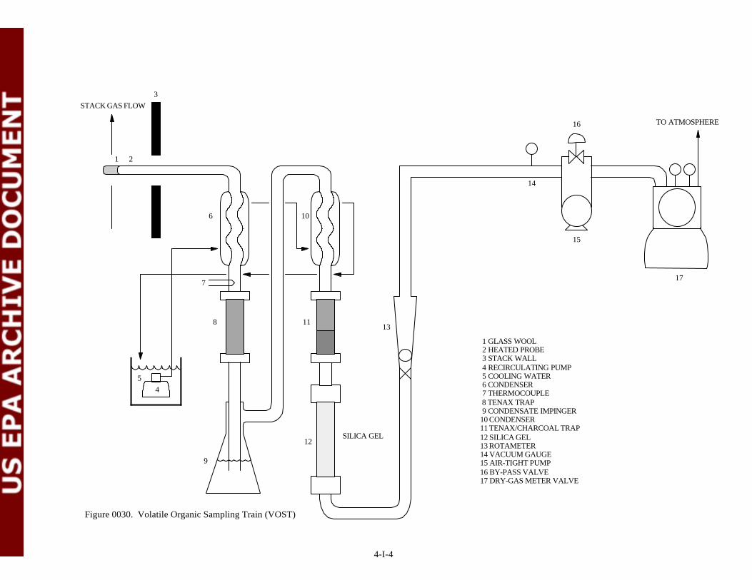
4-I-4
1 GLASS WOOL 2 HEATED PROBE 3 STACK WALL 4 RECIRCULATING PUMP 5 COOLING WATER 6 CONDENSER 7 THERMOCOUPLE 8 TENAX TRAP 9 CONDENSATE IMPINGER10 CONDENSER11 TENAX/CHARCOAL TRAP12 SILICA GEL13 ROTAMETER14 VACUUM GAUGE15 AIR-TIGHT PUMP16 BY-PASS VALVE17 DRY-GAS METER VALVE
Figure 0030. Volatile Organic Sampling Train (VOST)
TO ATMOSPHERE
12
13
17
15
16
SILICA GEL
6 10
8
5
4
3
21
14
11
STACK GAS FLOW
9
7

ATTACHMENT J
METHOD 0030 VOLATILE ORGANICS SAMPLING TRAIN SAMPLE RECOVERY CHECKLIST
(2 Sheets)

METHOD 0030 VOLATILE ORGANICS SAMPLE RECOVERY CHECKLIST
Facility Name: Unit: Observer: Test No. / Description: Run No.: Date: Run Start Time: Run Stop Time:
4-J-1
Observation / Requirement YES NO Comment
Was the sample train disassembled at the sample port location? If so, were theopenings of the test train components (adsorbent traps, condensate trap, etc.)sealed before being relocated to the recovery area? Were the componentssealed with Teflon tape or noncontaminating caps?®
Was the condensate sample collected for each tube set?
Was the total condensate sample collected at the conclusion of the test run?
Were the openings of the adsorbent traps capped after removal from the sampletrain and replaced into the original storage vials?
Was the condensate sample collected into an amber glass volatile organicanalysis (VOA) vial with a Teflon septum screw cap?®
Was organic-free water added to the condensate VOA vial to ensure no airbubbles were present?
Were at least three tube sets collected during the test run?
Was a fourth tube set collected during the test run for archiving purposes?
Was a reagent blank of the organic-free water collected according to theapproved TBP? If so, indicate the sample identifiers in the Comment column.
Was a blank sample train prepared and recovered at the sample location? Howlong did the blank train remain intact before recovery?
Were the condensate VOA vial and adsorbent tubes properly labeled and storedon ice promptly after recovery?

METHOD 0030 VOLATILE ORGANICS SAMPLE RECOVERY CHECKLIST
Facility Name: Unit: Observer: Test No. / Description: Run No.: Date: Run Start Time: Run Stop Time:
Observation / Requirement YES NO Comment
4-J-2
Was a trip blank pair of adsorbent tubes included with each sample shipmentto the laboratory?
Were the chain of custody and request for analysis forms completed by therecovery personnel ?
Were the appropriate signature(s) affixed to the chain of custody forms?
GENERAL OBSERVATIONS AND COMMENTS

ATTACHMENT K
METHOD 0040 TOTAL ORGANICS TEDLAR BAG SAMPLING CHECKLIST®
(5 Sheets)

4-K-1
METHOD 0040 TOTAL ORGANICS TEDLAR BAG SAMPLING CHECKLIST®
Facility Name: Run Number: Observer Signature: Test No./Description: Run Start Time: Unit: Run Stop Time: Date of Observation:
Observation / Requirement YES NO Comment
Did the train components appear to be clean and were all glassware openingscovered with Teflon film or noncontaminating caps before the train was®
assembled?
Was the train assembled by personnel in a manner that minimizedcontamination potential?
Was the train constructed of the components and materials identified inMethod 0040 (See Figure 0040: probe, filter holder, three-way valves,condenser assembly, knockout impinger, Tedlar bag, rigid container, control®
console, etc.)?
Were the dry gas meter, thermocouples, pitot, and critical orifice devices Dry gas metercalibrated prior to the test? If yes, provide the calibration dates in the ThermocouplesComment column. If available, attach a copy of the calibration records. Pitot
Critical orifice
Were weather conditions adverse to sampling (rain, snow, etc.)? If so,describe the measures taken to protect the sampling equipment in theComment column.
Was the sampling area (for example, the platform) kept clean and orderlyduring the run?
Were the traverse sample points determined in accordance with Method 1?
Was a cyclonic flow check made before the start of testing? If yes, recordthe date and time the check was completed in the Comment column.
Were stack gas oxygen, carbon dioxide, and carbon monoxide concentrationmeasured by orsat, fyrite, or CEMS?
Was the Tedlar bag purged three times with high purity nitrogen before®
sampling?
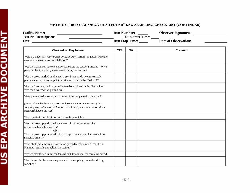
METHOD 0040 TOTAL ORGANICS TEDLAR BAG SAMPLING CHECKLIST (CONTINUED)®
Facility Name: Run Number: Observer Signature: Test No./Description: Run Start Time: Unit: Run Stop Time: Date of Observation:
Observation / Requirement YES NO Comment
4-K-2
Were the three-way valve bodies constructed of Teflon or glass? Were the®
stopcock valves constructed of Teflon ?®
Was the manometer leveled and zeroed before the start of sampling? Wereperiodic checks made by the operator during the test run?
Was the probe marked or alternative provisions made to ensure nozzleplacements at the traverse point locations determined by Method 1?
Was the filter tared and inspected before being placed in the filter holder?Was the filter made of quartz fiber?
Were pre-test and post-test leak checks of the sample train conducted?
(Note: Allowable leak rate is 0.1 inch Hg over 1 minute or 4% of thesampling rate, whichever is less, at 15 inches Hg vacuum or lower if notexceeded during the run.)
Was a pre-test leak check conducted on the pitot tube?
Was the probe tip positioned at the centroid of the gas stream forproportional sampling criteria? ---OR---Was the probe tip positioned at the average velocity point for constant ratesampling criteria?
Were stack gas temperature and velocity head measurements recorded at5 minute intervals throughout the test run?
Was ice maintained in the condensing bath throughout the sampling period?
Was the annulus between the probe and the sampling port sealed duringsampling?
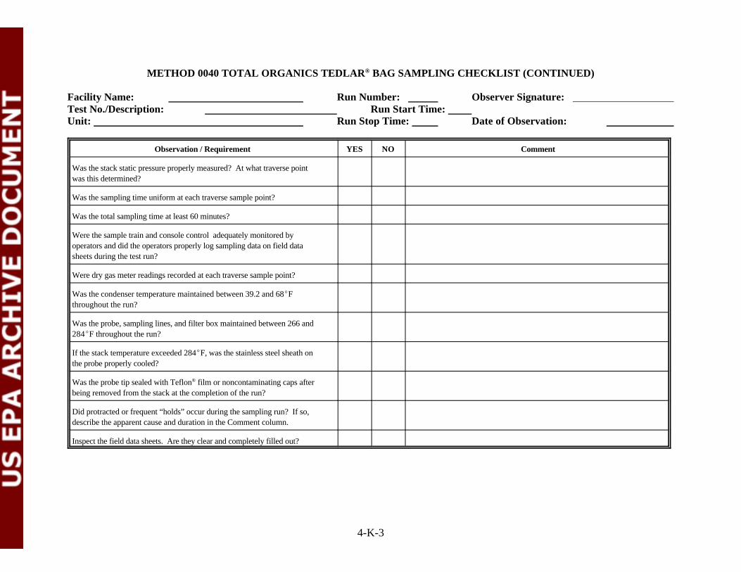
METHOD 0040 TOTAL ORGANICS TEDLAR BAG SAMPLING CHECKLIST (CONTINUED)®
Facility Name: Run Number: Observer Signature: Test No./Description: Run Start Time: Unit: Run Stop Time: Date of Observation:
Observation / Requirement YES NO Comment
4-K-3
Was the stack static pressure properly measured? At what traverse pointwas this determined?
Was the sampling time uniform at each traverse sample point?
Was the total sampling time at least 60 minutes?
Were the sample train and console control adequately monitored byoperators and did the operators properly log sampling data on field datasheets during the test run?
Were dry gas meter readings recorded at each traverse sample point?
Was the condenser temperature maintained between 39.2 and 68EFthroughout the run?
Was the probe, sampling lines, and filter box maintained between 266 and284EF throughout the run?
If the stack temperature exceeded 284EF, was the stainless steel sheath onthe probe properly cooled?
Was the probe tip sealed with Teflon film or noncontaminating caps after®
being removed from the stack at the completion of the run?
Did protracted or frequent “holds” occur during the sampling run? If so,describe the apparent cause and duration in the Comment column.
Inspect the field data sheets. Are they clear and completely filled out?
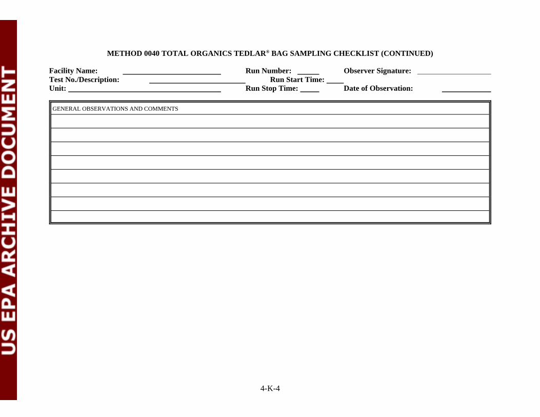
METHOD 0040 TOTAL ORGANICS TEDLAR BAG SAMPLING CHECKLIST (CONTINUED)®
Facility Name: Run Number: Observer Signature: Test No./Description: Run Start Time: Unit: Run Stop Time: Date of Observation:
4-K-4
GENERAL OBSERVATIONS AND COMMENTS
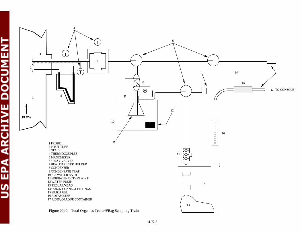
1 PROBE 2 PITOT TUBE 3 STACK 4 THERMOCOUPLES 5 MANOMETER 6 3-WAY VALVES 7 HEATED FILTER HOLDER 8 CONDENSER 9 CONDENSATE TRAP10 ICE WATER BATH11 SPIKING INJECTION PORT 12 WATER PUMP13 TEDLAR R BAG14 QUICK-CONNECT FITTINGS15 SILICA GEL16 ROTAMETER 17 RIGID, OPAQUE CONTAINER
1
2
35
7
8
10
12
TO CONSOLE
15
16
6
13
17
11
4
9
14
Figure 0040. Total Organics Tedlar R Bag Sampling Train
FLOW
T
4-K-5
ATTACHMENT L
METHOD 0040 TOTAL ORGANICS TEDLAR BAG SAMPLE RECOVERY CHECKLIST®
(2 Sheets)

4-L-1
METHOD 0040 TOTAL ORGANICS TEDLAR BAG SAMPLE RECOVERY CHECKLIST®
Facility Name: Run Number: Observer Signature: Test No./Description: Run Start Time: Unit: Run Stop Time: Date of Observation:
Observation / Requirement YES NO Comment
Was at least 15 liters of gas sample collected over the test period?
Was the Tedlar bag at least 80% full at the conclusion of the test period?®
Was the sample train disassembled at the sample port location? If so, werethe openings of the test train components (condenser, condensate trap, etc.)sealed before being relocated to the recovery area? Were the componentssealed with Teflon tape or noncontaminating caps?®
If present, was condensate in the trap, condenser, and sample line recoveredinto a measuring cylinder?
Did the sample train recovery include a triplicate rinse of the condensatetrap, condenser, and sample line with high-performance liquidchromatography (HPLC) grade water?
Were the component rinses collected in the measuring cylinder with thecondensate? Was the total volume recorded?
Were the contents in the measuring cylinder transferred to an amber glassvolatile organic analysis (VOA) vial with a Teflon septum screw cap?®
Was HPLC grade water added to the VOA vial to ensure no air bubbles werepresent?
Did the recovery personnel visually inspect the sample train componentsafter the rinses?
At the conclusion of the sample train recovery, were the openings of thesample train components sealed with Teflon tape or noncontaminating®
caps?
Was a reagent blank of the HPLC grade water collected according to thesampling plan? If so, indicate the sample identifiers in the Commentcolumn.

METHOD 0040 TOTAL ORGANICS TEDLAR BAG SAMPLE RECOVERY CHECKLIST (CONTINUED)®
Facility Name: Run Number: Observer Signature: Test No./Description: Run Start Time: Unit: Run Stop Time: Date of Observation:
Observation / Requirement YES NO Comment
4-L-2
Was a blank sample train prepared and recovered at the sample location? How long did the blank train remain intact before recovery?
Was the VOA vial properly labeled and stored on ice promptly afterrecovery?
Were the chain of custody and request for analysis forms completed by therecovery personnel ?
Were the appropriate signature(s) affixed to the chain of custody forms?
Were the Tedlar bag and VOA vial samples transported to the laboratory®
immediately after recovery?
Were the samples analyzed within 72 hours of collection by GC/FID?
GENERAL OBSERVATIONS AND COMMENTS
METHOD 0040 TOTAL ORGANICS TEDLAR BAG SAMPLE RECOVERY CHECKLIST (CONTINUED)®
Facility Name: Run Number: Observer Signature: Test No./Description: Run Start Time: Unit: Run Stop Time: Date of Observation:
4-L-3
ATTACHMENT M
METHOD 0050 PARTICULATE/HCl/Cl SAMPLING CHECKLIST2
(5 Sheets)

4-M-1
METHOD 0050 PARTICULATE/HCl/Cl SAMPLING CHECKLIST2
Facility Name: Run Number: Observer Signature: Test No./Description: Run Start Time: Unit: Run Stop Time: Date of Observation:
Observation / Requirement YES NO Comment
Did the train components appear to be clean and were all glassware openingscovered with Teflon film or noncontaminating caps before the train was®
assembled?
Was the train assembled by personnel in a manner that minimizedcontamination potential?
Was the train constructed of the components and materials identified inMethod 0050 (See Figure 0050: nozzle, heated probe, filter holder, 5-6impingers in ice bath, control console, etc.)?
Was the dry gas meter, thermocouples, nozzle, and critical orifice devices Dry gas metercalibrated prior to the test? If yes, provide the calibration date in the ThermocouplesComment column. If available, attach a copy of the calibration records. Critical orifice
Nozzle
Were weather conditions adverse to sampling (rain, snow, etc.)? If so,describe the measures taken to protect the sampling equipment in theComment column.
Was the sampling area (i.e., platform) kept clean and orderly during the run?
Were the traverse sample points determined in accordance with Method 1?
Was a cyclonic flow check made before the start of testing? If yes, recordthe date and time the check was completed in the Comment column.
Was stack gas oxygen, carbon dioxide, and carbon monoxide concentrationmeasured by orsat, fyrite, or CEMS?
Was the manometer leveled and zeroed before the start of sampling? Wereperiodic checks made by the operator during the test run?
Was the probe marked or alternative provisions made to ensure nozzleplacements at the traverse point locations determined by Method 1?

METHOD 0050 PARTICULATE/HCl/Cl SAMPLING CHECKLIST (CONTINUED)2
Facility Name: Run Number: Observer Signature: Test No./Description: Run Start Time: Unit: Run Stop Time: Date of Observation:
Observation / Requirement YES NO Comment
4-M-2
Was the filter tared and inspected before being placed in the filter holder?Was the filter made of Teflon , quartz, or glass fiber?®
Was the filter labeled or marked so as to identify it in the trian or elsewherewhould it be removed?
Was the filter supported with a Teflon frit?®
Was the nozzle made of glass?
Was stopcock grease used to seal ground glass ball joints?
Was a leak check of the sample train performed before and after each port Time Resultchange? Traverse # 1 Before
(Note: Allowable leak rate is 0.02 cfm or 4% of the average sampling rate, Traverse # 2 Before whichever is less, at 15 inches Hg vacuum or lower if not exceeded during Traverse # 2 After the run.)
Traverse # 1 After
Was a pre-test leak check conducted on the pitot tube?
Was the nozzle tip positioned at the proper traverse sample pointthroughout the test run?
Did operators make timely adjustments to sampling rates to maintainisokinetic conditions throughout the run?
Was the annulus between the probe and the sampling port sealed duringsampling?
Was the sample gas temperature exiting the last impinger maintained at orbelow 68EF throughout the test run?
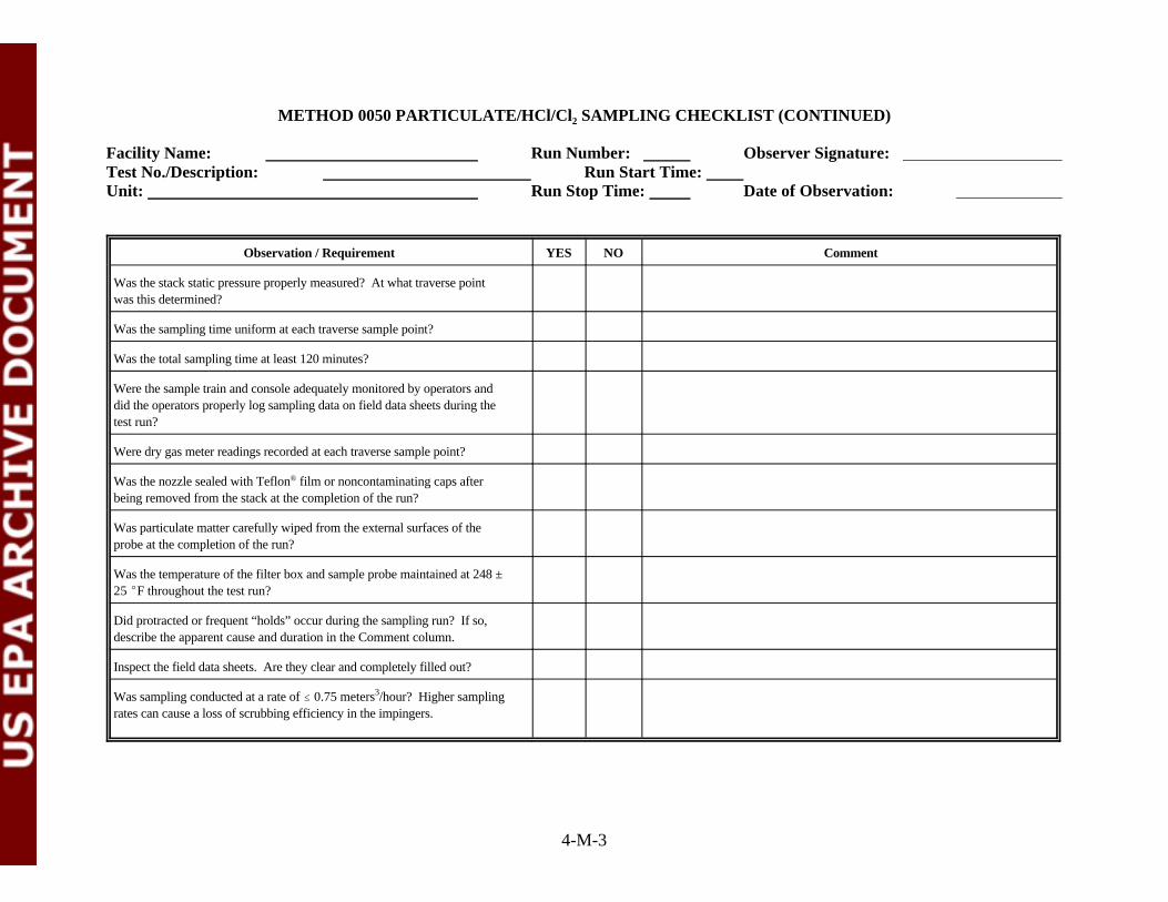
METHOD 0050 PARTICULATE/HCl/Cl SAMPLING CHECKLIST (CONTINUED)2
Facility Name: Run Number: Observer Signature: Test No./Description: Run Start Time: Unit: Run Stop Time: Date of Observation:
Observation / Requirement YES NO Comment
4-M-3
Was the stack static pressure properly measured? At what traverse pointwas this determined?
Was the sampling time uniform at each traverse sample point?
Was the total sampling time at least 120 minutes?
Were the sample train and console adequately monitored by operators anddid the operators properly log sampling data on field data sheets during thetest run?
Were dry gas meter readings recorded at each traverse sample point?
Was the nozzle sealed with Teflon film or noncontaminating caps after®
being removed from the stack at the completion of the run?
Was particulate matter carefully wiped from the external surfaces of theprobe at the completion of the run?
Was the temperature of the filter box and sample probe maintained at 248 ±25 EF throughout the test run?
Did protracted or frequent “holds” occur during the sampling run? If so,describe the apparent cause and duration in the Comment column.
Inspect the field data sheets. Are they clear and completely filled out?
Was sampling conducted at a rate of # 0.75 meters /hour? Higher sampling3
rates can cause a loss of scrubbing efficiency in the impingers.

METHOD 0050 PARTICULATE/HCl/Cl SAMPLING CHECKLIST (CONTINUED)2
Facility Name: Run Number: Observer Signature: Test No./Description: Run Start Time: Unit: Run Stop Time: Date of Observation:
4-M-4
GENERAL OBSERVATIONS AND COMMENTS

4-M-5
1 REVERSE - TYPE PITOT TUBE 2 PROBE 3 THERMOCOUPLE 4 STACK WALL 5 MANOMETER 6 THERMOCOUPLE 7 FILTER HOLDER 8 THERMOCOUPLE 9 CHECK VALVE10 FLEXIBLE VACUUM LINE11 VACUUM GAUGE12 MAIN VALVE13 BY- PASS VALVE14 AIR-TIGHT PUMP15 DRY GAS METER16 THERMOCOUPLE17 ORIFICE18 MANOMETER
Figure 0050. Particulate, Hydrogen Chloride, and Chlorine Sampling Train
TO ATMOSPHERE
17
18 15 14
16 1613
12 11
10
98
SILICA GEL
HEATED AREA
6
7
5
4STACK GAS FLOW
3
2
1
3
2
1
0.1N H2SO4 0.1N NaOH
ICE BATH
EMPTYEMPTY

ATTACHMENT N
METHOD 0050 PARTICULATE/HCl/Cl SAMPLING RECOVERY CHECKLIST2
(3 Sheets)

4-N-1
METHOD 0050 PARTICULATE/HCl/Cl SAMPLE RECOVERY CHECKLIST2
Facility Name: Run Number: Observer Signature: Test No./Description: Run Start Time: Unit: Run Stop Time: Date of Observation:
Observation / Requirement YES NO Comment
Was condensate present in the sample train “front half” or did the filterappear to be wet? If so, how long was the post test conditioning periodconducted on the sample train and at what )H rate? Was the ambient airpurified through ascarite, sodium hydroxide, activated carbon or some othermedia?
Was the sample train disassembled at the sample port location? If so, werethe openings of the test train components (probe, filter bell, impinger train,etc.) sealed before being relocated to the recovery area? Were thecomponents sealed with Teflon tape or noncontaminating caps?®
Was particulate matter visible on the filter? If so, describe the appearance(color, particle size, etc.) in the Comment column.
Was there any evidence that particulate matter may have bypassed thefilter? If so, describe in the Comment column.
Was the filter recovered with tweezers and loose particulate inside the filterbell collected into the original petri dish? Was the petri dish sealed withTeflon tape?®
Was the filter recovered intact without loss of particulate?
Did the “front half” sample train recovery include: an acetone rinse of thenozzle; triplicate brushing and an acetone rinse of the liner; brushing andacetone rinse of the filter bell inlet; and, an acetone rinse of the brush?
Were all of the “front half” rinses collected in a labeled sample container?
Did the recovery personnel visually inspect the “front half” sample traincomponents after the rinses?
Were the impingers weighed or measured for moisture content determinationbefore recovery of the solution contents?
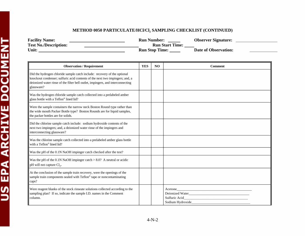
METHOD 0050 PARTICULATE/HCl/Cl SAMPLING CHECKLIST (CONTINUED)2
Facility Name: Run Number: Observer Signature: Test No./Description: Run Start Time: Unit: Run Stop Time: Date of Observation:
Observation / Requirement YES NO Comment
4-N-2
Did the hydrogen chloride sample catch include: recovery of the optionalknockout condenser; sulfuric acid contents of the next two impingers; and, adeionized water rinse of the filter bell outlet, impingers, and interconnectingglassware?
Was the hydrogen chloride sample catch collected into a prelabeled amberglass bottle with a Teflon lined lid? ®
Were the sample containers the narrow neck Boston Round type rather thanthe wide mouth Packer Bottle type? Boston Rounds are for liquid samples,the packer bottles are for solids.
Did the chlorine sample catch include: sodium hydroxide contents of thenext two impingers; and, a deionized water rinse of the impingers andinterconnecting glassware?
Was the chlorine sample catch collected into a prelabeled amber glass bottlewith a Teflon lined lid?®
Was the pH of the 0.1N NaOH impinger catch checked after the test?
Was the pH of the 0.1N NaOH impinger catch > 8.0? A neutral or acidic
pH will not capture Cl .2
At the conclusion of the sample train recovery, were the openings of thesample train components sealed with Teflon tape or noncontaminating®
caps?
Were reagent blanks of the stock rinseate solutions collected according to the Acetone___________________________________________sampling plan? If so, indicate the sample I.D. names in the Comment Deionized Water___________________________________column. Sulfuric Acid_____________________________________
Sodium Hydroxide__________________________________
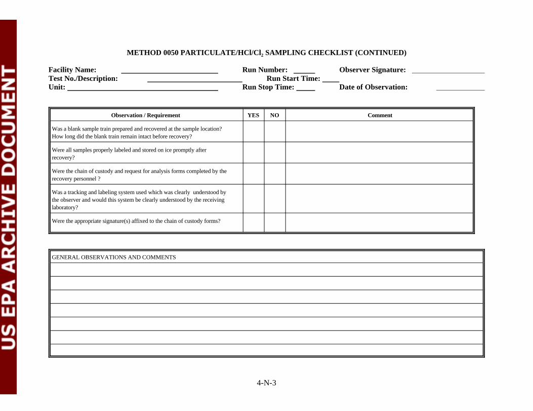
METHOD 0050 PARTICULATE/HCl/Cl SAMPLING CHECKLIST (CONTINUED)2
Facility Name: Run Number: Observer Signature: Test No./Description: Run Start Time: Unit: Run Stop Time: Date of Observation:
Observation / Requirement YES NO Comment
4-N-3
Was a blank sample train prepared and recovered at the sample location? How long did the blank train remain intact before recovery?
Were all samples properly labeled and stored on ice promptly afterrecovery?
Were the chain of custody and request for analysis forms completed by therecovery personnel ?
Was a tracking and labeling system used which was clearly understood bythe observer and would this system be clearly understood by the receivinglaboratory?
Were the appropriate signature(s) affixed to the chain of custody forms?
GENERAL OBSERVATIONS AND COMMENTS

ATTACHMENT O
METHOD 0060 MULTIPLE METALS SAMPLING CHECKLIST
(4 Sheets)

4-O-1
METHOD 0060 MULTIPLE METALS SAMPLING CHECKLIST
Facility Name: Run Number: Observer Signature: Test No./Description: Run Start Time: Unit: Run Stop Time: Date of Observation:
Observation / Requirement YES NO Comment
Were all of the train’s glassware components cleaned before testing byrinsing with hot tap water, and then washed in hot soapy water, rinsed withtap and deionized water? Was this washing followed by soaking in10 percent HNO for 4 hours, rinsing with deionized water, and final rinsing3
with acetone?
Did the train components appear to be clean and were all glassware openingscovered with Teflon film before the train was assembled?®
Was the acidic potassium permanganate absorbing solution made fresh onthe test day and stored in an amber glass container with a Teflon lined cap?®
Was the train assembled by personnel in a manner that minimizedcontamination potential?
Was the train constructed of the components and materials identified inMethod 0060 (See Figure 0012: nozzle, heated probe, filter holder,4-7 impingers in ice bath, control console, etc.)?
Was the nozzle and probe liner constructed of glass or quartz?
Was the dry gas meter, thermocouples, nozzle, and critical orifice devices Dry gas metercalibrated prior to the test? If yes, provide the calibration date in the ThermocouplesComment column. If available, attach a copy of the calibration records. Critical orifice
Nozzle
Were weather conditions adverse to sampling (rain, snow, etc.)? If so,describe the measures taken to protect the sampling equipment in theComment column.
Was the sampling area (for example, the platform) kept clean and orderlyduring the run?
Were the traverse sample points determined in accordance with Method 1?

METHOD 0060 MULTIPLE METALS SAMPLING CHECKLIST (CONTINUED)
Facility Name: Run Number: Observer Signature: Test No./Description: Run Start Time: Unit: Run Stop Time: Date of Observation:
Observation / Requirement YES NO Comment
4-O-2
Was a cyclonic flow check made before the start of testing? If yes, recordthe date and time the check was completed in the Comment column.
Was stack gas oxygen, carbon dioxide, and carbon monoxide concentrationmeasured by orsat, fyrite, or CEMS?
Was the manometer leveled and zeroed before the start of sampling? Wereperiodic checks made by the operator during the test run?
Was the probe marked or alternative provisions made to ensure nozzleplacements at the traverse point locations determined by Method 1?
Was the filter tared and inspected before being placed in the filter holder?Was the filter made of quartz or glass fiber?
Was the filter supported by a Teflon frit?®
Was a leak check of the sample train performed before and after each port Time Resultchange? Traverse # 1 Before
(Note: Allowable leak rate is 0.02 cfm or 4% of the average sampling rate, Traverse # 2 Before whichever is less, at 15 inches Hg vacuum or lower if not exceeded during Traverse # 2 After the run.)
Traverse # 1 After
Was a pre-test leak check conducted on the pitot tube?
Was the nozzle tip positioned at the proper traverse sample pointthroughout the test run?
Did operators make timely adjustments to sampling rates to maintainisokinetic conditions throughout the run?
Was the annulus between the probe and the sampling port sealed duringsampling?

METHOD 0060 MULTIPLE METALS SAMPLING CHECKLIST (CONTINUED)
Facility Name: Run Number: Observer Signature: Test No./Description: Run Start Time: Unit: Run Stop Time: Date of Observation:
Observation / Requirement YES NO Comment
4-O-3
Was the sample gas temperature exiting the last impinger maintained at orbelow 68EF throughout the test run?
Was the stack static pressure properly measured? At what traverse pointwas this determined?
Was the sampling time uniform at each traverse sample point?
Was the total sampling time at least 120 minutes?
Was the sampling rate kept at or below 0.75 m per hour (#0.75 m /hour)?3 3
Were the sample train and console adequately monitored by operators anddid the operators properly log sampling data on field data sheets during thetest run?
Were dry gas meter readings recorded at each traverse sample point?
Was the nozzle sealed with Teflon film after being removed from the stack®
at the completion of the run?
Was particulate matter carefully wiped from the external surfaces of theprobe at the completion of the run?
Was the temperature of the filter box and sample probe maintained at 248 ±25EF throughout the test run?
Did protracted or frequent “holds” occur during the sampling run? If so,describe the apparent cause and duration in the Comment column.
Inspect the field data sheets. Are they clear and completely filled out?

METHOD 0060 MULTIPLE METALS SAMPLING CHECKLIST (CONTINUED)
Facility Name: Run Number: Observer Signature: Test No./Description: Run Start Time: Unit: Run Stop Time: Date of Observation:
4-O-4
GENERAL OBSERVATIONS AND COMMENTS

1 REVERSE - TYPE PITOT TUBE 2 GLASS PROBE 3 THERMOCOUPLE 4 STACK WALL 5 MANOMETER 6 THERMOCOUPLE 7 FILTER HOLDER 8 THERMOCOUPLE 9 CHECK VALVE10 FLEXIBLE VACUUM LINE11 VACUUM GAUGE12 MAIN VALVE13 BY- PASS VALVE14 AIR-TIGHT PUMP15 DRY GAS METER16 THERMOCOUPLE17 ORIFICE18 MANOMETER
Figure 0060. Multiple Metals Sampling Train
TO ATMOSPHERE
17
18 15 14
16 1613
12 11
10
98
SILICA GEL
HEATED AREA
6
7
5
4STACK GAS FLOW
3
2
1
3
2
1
5% HNO3/10% H2O2 4% KMnO4/10% H2SO4
ICE BATH
EMPTY EMPTY
4-O-5

ATTACHMENT P
METHOD 0060 MULTIPLE METALS SAMPLE RECOVERY CHECKLIST
(5 Sheets)
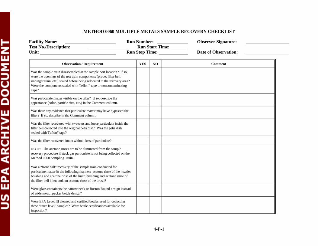
4-P-1
METHOD 0060 MULTIPLE METALS SAMPLE RECOVERY CHECKLIST
Facility Name: Run Number: Observer Signature: Test No./Description: Run Start Time: Unit: Run Stop Time: Date of Observation:
Observation / Requirement YES NO Comment
Was the sample train disassembled at the sample port location? If so,were the openings of the test train components (probe, filter bell,impinger train, etc.) sealed before being relocated to the recovery area?Were the components sealed with Teflon tape or noncontaminating®
caps?
Was particulate matter visible on the filter? If so, describe theappearance (color, particle size, etc.) in the Comment column.
Was there any evidence that particulate matter may have bypassed thefilter? If so, describe in the Comment column.
Was the filter recovered with tweezers and loose particulate inside thefilter bell collected into the original petri dish? Was the petri dishsealed with Teflon tape?®
Was the filter recovered intact without loss of particulate?
NOTE: The acetone rinses are to be eliminated from the samplerecovery procedure if stack gas particulate is not being collected on theMethod 0060 Sampling Train.
Was a “front half” recovery of the sample train conducted forparticulate matter in the following manner: acetone rinse of the nozzle;brushing and acetone rinse of the liner; brushing and acetone rinse ofthe filter bell inlet; and, an acetone rinse of the brush?
Were glass containers the narrow neck or Boston Round design insteadof wide mouth packer bottle design?
Were EPA Level III cleaned and certified bottles used for collectingthese “trace level” samples? Were bottle certifications available forinspection?
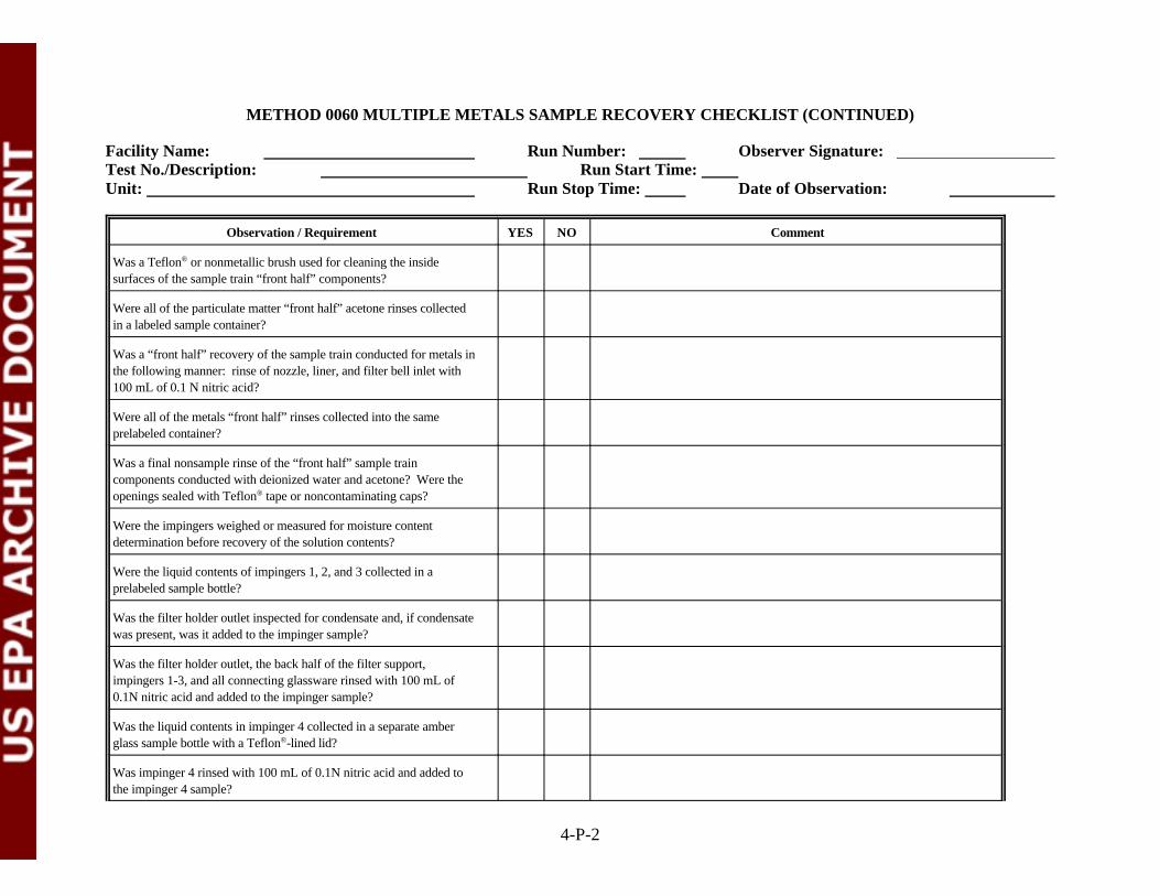
METHOD 0060 MULTIPLE METALS SAMPLE RECOVERY CHECKLIST (CONTINUED)
Facility Name: Run Number: Observer Signature: Test No./Description: Run Start Time: Unit: Run Stop Time: Date of Observation:
Observation / Requirement YES NO Comment
4-P-2
Was a Teflon or nonmetallic brush used for cleaning the inside®
surfaces of the sample train “front half” components?
Were all of the particulate matter “front half” acetone rinses collectedin a labeled sample container?
Was a “front half” recovery of the sample train conducted for metals inthe following manner: rinse of nozzle, liner, and filter bell inlet with100 mL of 0.1 N nitric acid?
Were all of the metals “front half” rinses collected into the sameprelabeled container?
Was a final nonsample rinse of the “front half” sample traincomponents conducted with deionized water and acetone? Were theopenings sealed with Teflon tape or noncontaminating caps?®
Were the impingers weighed or measured for moisture contentdetermination before recovery of the solution contents?
Were the liquid contents of impingers 1, 2, and 3 collected in aprelabeled sample bottle?
Was the filter holder outlet inspected for condensate and, if condensatewas present, was it added to the impinger sample?
Was the filter holder outlet, the back half of the filter support,impingers 1-3, and all connecting glassware rinsed with 100 mL of0.1N nitric acid and added to the impinger sample?
Was the liquid contents in impinger 4 collected in a separate amberglass sample bottle with a Teflon -lined lid?®
Was impinger 4 rinsed with 100 mL of 0.1N nitric acid and added tothe impinger 4 sample?

METHOD 0060 MULTIPLE METALS SAMPLE RECOVERY CHECKLIST (CONTINUED)
Facility Name: Run Number: Observer Signature: Test No./Description: Run Start Time: Unit: Run Stop Time: Date of Observation:
Observation / Requirement YES NO Comment
4-P-3
Did the 4 percent KmnO /10 percent H SO impingers maintain their4 2 4
deep purple color through the sampling and sample recovery process?
Were the liquid contents of impingers 5 and 6 collected in a separateamber glass bottle with a Teflon -lined lid?®
Were impingers 5 and 6 and connecting glassware triple rinsed with100 mL of the acidified potassium permanganate solution and therinsate added to the impinger 5 and 6 sample?
Were impingers 5 and 6 and connecting glassware triple rinsed with100 mL of deionized water and the rinsate added to the impinger 5 and6 sample?
Did the recovery personnel visually inspect impingers 5 and 6 forresidue deposits or discoloration following the deionized water rinse?
If residue deposits or discoloration remained in impingers 5 and 6,were they rinsed with 25 mL of 8N hydrogen chloride and collectedinto a separate amber glass bottle with a Teflon -lined cap containing®
200 mL deionized water?
Was the silica gel impinger weighed to the nearest 0.5g?
At the conclusion of the sample train recovery, were the openings ofthe sample train components sealed with Teflon tape or®
noncontaminating caps?

METHOD 0060 MULTIPLE METALS SAMPLE RECOVERY CHECKLIST (CONTINUED)
Facility Name: Run Number: Observer Signature: Test No./Description: Run Start Time: Unit: Run Stop Time: Date of Observation:
Observation / Requirement YES NO Comment
4-P-4
Were reagent blanks of the stock solutions collected according to the Acetone_________________________________________sampling plan? If so, indicate the sample identifiers in the Comment Deionized water__________________________________column. 0.1N HNO ______________________________________3
5%HNO /10%H O ________________________________3 2 2
4%KMnO /10%H SO ______________________________4 2 4
8N HCl__________________________________________Particulate Filters (3)_______________________________
Was a blank sample train prepared and recovered at the samplelocation? How long did the blank train remain intact before recovery?
Was the blank train placed on the stack or at the base of the stack for aperiod of time equivalent to one run, leak checked before and after thetest, and heated to temperature for the duration of one test run?
Were all samples properly labeled and stored on ice promptly afterrecovery?
Were the chain of custody and request for analysis forms completedby the recovery personnel ?
Was a tracking and labeling system used which was clearly understoodby the observer and would this system be clearly understood by thereceiving laboratory?
Were the appropriate signature(s) affixed to the chain of custodyforms?

METHOD 0060 MULTIPLE METALS SAMPLE RECOVERY CHECKLIST (CONTINUED)
Facility Name: Run Number: Observer Signature: Test No./Description: Run Start Time: Unit: Run Stop Time: Date of Observation:
4-P-5
GENERAL OBSERVATIONS AND COMMENTS

ATTACHMENT Q
METHOD 0061 HEXAVALENT CHROMIUM SAMPLING CHECKLIST
(3 Sheets)

4-Q-1
METHOD 0061 HEXAVALENT CHROMIUM SAMPLING CHECKLIST
Facility Name: Run Number: Observer Signature: Test No./Description: Run Start Time: Unit: Run Stop Time: Date of Observation:
Observation / Requirement Y N Comment
Did the train components appear to be clean and were all glassware openingscovered with Teflon film before the train was assembled?
Was the train assembled by personnel in a manner that minimizedcontamination potential?
Was the train constructed of the components and materials identified inMethod 0061 (See Figure 0061: recirculating glass or Teflon probe, Teflonsample line, 5 chilled Teflon impingers, etc.)?Note: The method prescribes a 0.1N KOH impinger solution for trappingCr . Experience has demonstrated that 0.1N is not sufficiently+6
concentrated to maintain a pH > 8.5 in the first impinger. The run will beruled invalid if the pH in the 1st impinger drops below 8.5, therefore, it isrecommended that at least a 1.0N KOH solution be used in the entire train.
Was the dry gas meter calibrated prior to the test? If yes, provide thecalibration date in the Comment column. If available, attach a copy of thecalibration record.
Were weather conditions adverse to sampling (rain, snow, etc.)? If so,describe the measures taken to protect the sampling equipment in theComment column.
Was the sampling area (for example, the platform) kept clean and orderlyduring the run?
Were sampling locations determined in accordance with Method 1?
Was a cyclonic flow check made before the start of testing? If yes, recordthe date and time the check was completed in the Comment column.
Were stack gas oxygen, carbon dioxide, and dry molecular weight determinedusing an Orsat analyzer?
Was the manometer leveled and zeroed before the start of sampling?
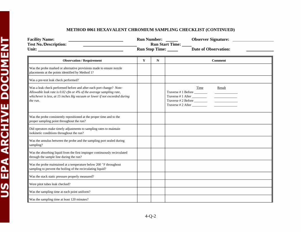
METHOD 0061 HEXAVALENT CHROMIUM SAMPLING CHECKLIST (CONTINUED)
Facility Name: Run Number: Observer Signature: Test No./Description: Run Start Time: Unit: Run Stop Time: Date of Observation:
Observation / Requirement Y N Comment
4-Q-2
Was the probe marked or alternative provisions made to ensure nozzleplacements at the points identified by Method 1?
Was a pre-test leak check performed?
Was a leak check performed before and after each port change? Note: Time ResultAllowable leak rate is 0.02 cfm or 4% of the average sampling rate, Traverse # 1 Before whichever is less, at 15 inches Hg vacuum or lower if not exceeded during Traverse # 1 After the run. Traverse # 2 Before
Traverse # 2 After
Was the probe consistently repositioned at the proper time and to theproper sampling point throughout the run?
Did operators make timely adjustments to sampling rates to maintainisokinetic conditions throughout the run?
Was the annulus between the probe and the sampling port sealed duringsampling?
Was the absorbing liquid from the first impinger continuously recirculatedthrough the sample line during the run?
Was the probe maintained at a temperature below 200 EF throughoutsampling to prevent the boiling of the recirculating liquid?
Was the stack static pressure properly measured?
Were pitot tubes leak checked?
Was the sampling time at each point uniform?
Was the sampling time at least 120 minutes?

METHOD 0061 HEXAVALENT CHROMIUM SAMPLING CHECKLIST (CONTINUED)
Facility Name: Run Number: Observer Signature: Test No./Description: Run Start Time: Unit: Run Stop Time: Date of Observation:
Observation / Requirement Y N Comment
4-Q-3
Were the sampling train and console adequately monitored by operators anddid the operators properly log sampling data on field data sheets duringsampling?
Was the nozzle covered with aluminum foil after being removed from thestack at the completion of the run?
Was particulate matter carefully wiped from the external surfaces of theprobe at the completion of the run?
Was the probe capped at both ends before being removed to the recoveryarea?
Did protracted or frequent “holds” occur during the sampling run?If so, describe the apparent cause and duration in the Comment column.
Inspect the field data sheets. Are they clear and complete and were theyreviewed by a senior member of the sampling team following the run?
GENERAL OBSERVATIONS AND COMMENTS

1 PROBE 2 STACK WALL 3 RECIRCULATING LIQUID IN TEFLON R LINE 4 THERMOCOUPLE 5 CHECK VALVE 6 FLEXIBLE VACUUM LINE 7 VACUUM GAUGE 8 MAIN VALVE 9 BY- PASS VALVE10 AIR-TIGHT PUMP11 DRY GAS METER12 THERMOCOUPLE13 ORIFICE14 MANOMETER15 TEFLON R IMPINGERS16 GLASS IMPINGER
Figure 0061. Hexavalent Chromium Sampling Train
TO ATMOSPHERE
14 11 10
12 129
8 7
6
5
4
SILICA GEL
5
STACK GAS FLOW
1
3
0.1N KOH
ICE BATH
13
EMPTYRECIRCULATES0.1N KOH FROMFIRST IMPINGER
15
16
4-Q-4

ATTACHMENT R
METHOD 0061 HEXAVALENT CHROMIUM SAMPLE RECOVERY CHECKLIST
(3 Sheets)

4-R-1
METHOD 0061 HEXAVALENT CHROMIUM SAMPLE RECOVERY CHECKLIST
Facility Name: Run Number: Observer Signature: Test No./Description: Run Start Time: Unit: Run Stop Time: Date of Observation:
Observation / Requirement Y N Comment
Was the train disassembled in a clean area in a manner that minimized thepotential for sample loss and/or contamination?
Was the pH of impinger 1 checked and determined to be greater than 8.5? Did the pH of the first impinger drop below 8.5 during the run?
Was nitrogen bubbled through the impinger train at approximately 10 litersper minute for 30 minutes?
Were the liquid contents of impingers 1, 2, 3, and 4 measured or weighed,and recorded on the recovery data sheets?
Were the liquid contents of impingers 1, 2, 3, and 4 placed in a polyethylenesample container?
Were the nozzle, probe, recirculating sample line, and first four impingersrinsed four times with distilled deionized water and were the rinses added tothe impinger sample?
Note: The 0.1N HNO back half rinse can be eliminated whenever Total3
Chomium is not being determined on this sampling train.
Were the “back half” of the filter holder, the filter support, and allconnecting glassware rinsed with 100 mL of 0.1N nitric acid and were therinses added to a separate polyethylene container?
Were the contents of the 0.1N KOH impinger composite filtered through a0.45µ acetate filter to remove insoluble matter?
Was the sample container rinsed 3 times with distilled deionized water andwas the rinse solution filtered with the sample?
Were the filter and reservoir rinsed 3 times and were these rinses added tothe sample being filtered?

METHOD 0061 HEXAVALENT CHROMIUM SAMPLE RECOVERY CHECKLIST (CONTINUED)
Facility Name: Run Number: Observer Signature: Test No./Description: Run Start Time: Unit: Run Stop Time: Date of Observation:
Observation / Requirement Y N Comment
4-R-2
Was the silica gel impinger weighed to the nearest 0.5g?
Were reagent blanks of 0.1N KOH impinger solution and deionized watercollected according to the sampling plan?
Were arrangements made with a laboratory that set up analysis of thesesamples within the 24 hour holding time required in SW-846 Method 7199? If the 24 hour holding time is not being used, is field spiking of the finalsample being conducted immediately after filtering is complete?
If field spiking is being conducted, were three portions of the original sampleset up so that one portion could be submitted to the analytical laboratoryunspiked, and the other portions spiked at 10 ppb and 25 ppb (or otherappropriate spike level)? All spiked samples are to be analyzed by thelaboratory.
Were all samples properly labeled and stored on ice promptly afterrecovery?
Were the chain of custody and request for analyses forms completed byrecovery personnel ?
Were the appropriate signature(s) affixed to the chain of custody forms?

METHOD 0061 HEXAVALENT CHROMIUM SAMPLE RECOVERY CHECKLIST (CONTINUED)
Facility Name: Run Number: Observer Signature: Test No./Description: Run Start Time: Unit: Run Stop Time: Date of Observation:
4-R-3
GENERAL OBSERVATIONS AND COMMENTS

ATTACHMENT S
METHOD 0031 VOLATILE ORGANICS SAMPLING TRAIN CHECKLIST
(3 Sheets)

4-S-1
METHOD 0031 VOLATILE ORGANICS SAMPLING TRAIN CHECKLIST
Facility Name: Run Number: Observer Signature: Test No./Description: Run Start Time: Unit: Run Stop Time: Date of Observation:
Observation / Requirement YES NO Comment
Note: The VOST is being used to characterize the stack gas for Products ofIncomplete Combustion (PICs). Some PICs have very low boiling pointswhich requires that the sampling rate be # 0.5 liters/minute and that the gassample entering the first Tenax resin tube be # 10 C. Otherwise losses ofo
analyte will occur. This is a three tube configuration.
Are all adsorbent tubes prepared for use on this trial burn prepared fromnew resin material, and specifically not been used at other sites?
Did the train components appear to be clean and were all glassware openingscovered with Teflon film or noncontaminating caps before the train was®
assembled?
Was the train assembled by personnel in a manner that minimizedcontamination potential?
Were all adsorbance tubes prepared within 2 weeks of the test?
Were the adsorbent tube cartridges stored on ice before use?
Are all adsorbent tubes prepared for use on this trial burn prepared fromnew resin material, and specifically not been used at other sites?
Was the train constructed of the components and materials identified inMethod 0031 (See Figure 0031: probe, valve, Tenax cartridges, condenser,condensate impinger, condenser, Anasorb® cartridge, silica gel impinger,etc.)?
Were the dry gas meter, thermocouples, and rotameter devices calibrated Dry gas meterprior to the test? If yes, provide the calibration dates in the Comment Thermocouplescolumn. If available, attach a copy of the calibration records. Rotameter
Were weather conditions adverse to sampling (rain, snow, etc.)? If so,describe the measures taken to protect the sampling equipment in theComment column.

METHOD 0031 VOLATILE ORGANICS SAMPLING TRAIN CHECKLIST (CONTINUED)
Facility Name: Run Number: Observer Signature: Test No./Description: Run Start Time: Unit: Run Stop Time: Date of Observation:
Observation / Requirement YES NO Comment
4-S-2
Was the sampling area (i.e., platform) kept clean and orderly during the run?
Were pre-test and post-test leak checks of the sample train conducted?(Note: Pre-test leak check should be <2.5 mm Hg over 1 minute. Post-testleak check should be <2.5 mm Hg over 1 minute at the highest sample trainvacuum encountered during the test period)
Was the sample rate approximately 0.5 liter/minute?
Was ice maintained in the condensing bath throughout the sampling period?
Was the gas temperature entering the first Tenax resin tube maintained at#10 C during sampling?o
Was the annulus between the probe and the sampling port sealed duringsampling?
Was the probe temperature maintained above 130EC throughout the testrun?
Were the sample train and console control adequately monitored by theoperator and did the operator properly log sampling data on field data sheetsduring the test run?
Was the probe tip sealed with Teflon film or noncontaminating caps after®
being removed from the stack at the completion of the run?
Was the total sampling time at least 40 minutes per VOST tube set?
Did protracted or frequent “holds” occur during the sampling run? If so,describe the apparent cause and duration in the Comment column.
Inspect the field data sheets. Are they clear and completely filled out?
METHOD 0031 VOLATILE ORGANICS SAMPLING TRAIN CHECKLIST (CONTINUED)
Facility Name: Run Number: Observer Signature: Test No./Description: Run Start Time: Unit: Run Stop Time: Date of Observation:
4-S-3
GENERAL OBSERVATIONS AND COMMENTS

1 GLASS WOOL 2 HEATED PROBE 3 STACK WALL 4 RECIRCULATING PUMP 5 COOLING WATER 6 CONDENSER 7 THERMOCOUPLE 8 TENAX TRAP 9 CONDENSATE IMPINGER10 CONDENSER11 ANASORB TRAP12 SILICA GEL13 ROTAMETER14 VACUUM GAUGE15 AIR-TIGHT PUMP16 BY-PASS VALVE17 DRY-GAS METER VALVE
Figure 0031. Volatile Organics Sampling Train (VOST)
TO ATMOSPHERE
12
13
17
15
16
SILICA GEL
6 10
8
5
4
3
21
14
11
STACK GAS FLOW
9
8
7
R
4-S-4

ATTACHMENT T
METHOD 0031 VOLATILE ORGANICS RECOVERY CHECKLIST
(2 Sheets)

4-T-1
METHOD 0031 VOLATILE ORGANICS SAMPLE RECOVERY CHECKLIST
Facility Name: Run Number: Observer Signature: Test No./Description: Run Start Time: Unit: Run Stop Time: Date of Observation:
Observation / Requirement YES NO Comment
Was the total condensate sample collected at the conclusion of the test run? Was the volume of the condensate measured and recorded at the end of therun?
Were the openings of the adsorbent traps capped after removal from thesample train and replaced into the original storage vials?
Was the condensate sample collected into an amber glass volatile organicanalysis (VOA) vial with a Teflon septum screw cap?®
If the volume of the condensate was less than 40 mLs, was organic-freewater added to the condensate VOA vial to ensure no air bubbles werepresent? If the volume of the condensate is > 40 mLs, only one VOAshould be filled with no air bubbles, and the remainder discarded.
Were at least three tube sets collected during the test run?
Was a fourth tube set collected during the test run for archiving purposes?
Was a reagent blank of the organic-free water collected according to theapproved TBP? If so, indicate the sample identifiers in the Commentcolumn.
Were the condensate VOA vial and adsorbent tubes properly labeled andstored on ice promptly after recovery?
Was a trip blank set of adsorbent tubes included with each sample shipmentto the laboratory?
Was a deionized water trip blank included with each shipment of condensatesamples to the laboratory?
Was a set of adsorbance tubes collected as field blanks during each trial burnrun?

METHOD 0031 VOLATILE ORGANICS SAMPLE RECOVERY CHECKLIST (CONTINUED)
Facility Name: Run Number: Observer Signature: Test No./Description: Run Start Time: Unit: Run Stop Time: Date of Observation:
Observation / Requirement YES NO Comment
4-T-2
Were two sets of spiked resin blanks prepared and analyzed before the trialburn commenced?
Were the chain of custody and request for analysis forms completed by therecovery personnel ?
Does the tracking and labeling system clearly indicate that for each set ofVOST tubes, the two Tenax tubes are to be analyzed together and theAnasorb® tube analyzed separately?
Were the appropriate signature(s) affixed to the chain of custody forms?
GENERAL OBSERVATIONS AND COMMENTS

ATTACHMENT U
METHOD 0023 PCDD/PCDF SAMPLING CHECKLIST
(4 Sheets)
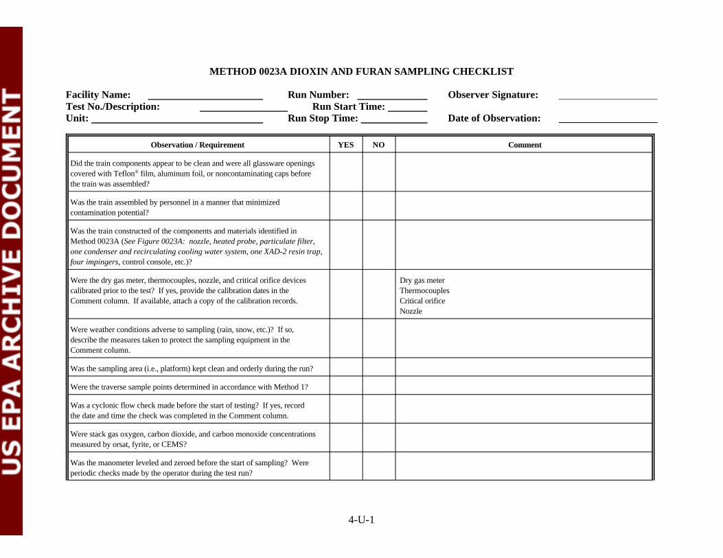
4-U-1
METHOD 0023A DIOXIN AND FURAN SAMPLING CHECKLIST
Facility Name: Run Number: Observer Signature: Test No./Description: Run Start Time: Unit: Run Stop Time: Date of Observation:
Observation / Requirement YES NO Comment
Did the train components appear to be clean and were all glassware openingscovered with Teflon film, aluminum foil, or noncontaminating caps before®
the train was assembled?
Was the train assembled by personnel in a manner that minimizedcontamination potential?
Was the train constructed of the components and materials identified inMethod 0023A (See Figure 0023A: nozzle, heated probe, particulate filter,one condenser and recirculating cooling water system, one XAD-2 resin trap,four impingers, control console, etc.)?
Were the dry gas meter, thermocouples, nozzle, and critical orifice devices Dry gas metercalibrated prior to the test? If yes, provide the calibration dates in the ThermocouplesComment column. If available, attach a copy of the calibration records. Critical orifice
Nozzle
Were weather conditions adverse to sampling (rain, snow, etc.)? If so,describe the measures taken to protect the sampling equipment in theComment column.
Was the sampling area (i.e., platform) kept clean and orderly during the run?
Were the traverse sample points determined in accordance with Method 1?
Was a cyclonic flow check made before the start of testing? If yes, recordthe date and time the check was completed in the Comment column.
Were stack gas oxygen, carbon dioxide, and carbon monoxide concentrationsmeasured by orsat, fyrite, or CEMS?
Was the manometer leveled and zeroed before the start of sampling? Wereperiodic checks made by the operator during the test run?
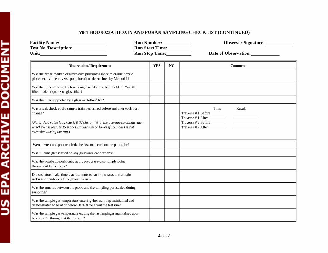
METHOD 0023A DIOXIN AND FURAN SAMPLING CHECKLIST (CONTINUED)
Facility Name: Run Number: Observer Signature: Test No./Description: Run Start Time: Unit: Run Stop Time: Date of Observation:
Observation / Requirement YES NO Comment
4-U-2
Was the probe marked or alternative provisions made to ensure nozzleplacements at the traverse point locations determined by Method 1?
Was the filter inspected before being placed in the filter holder? Was thefilter made of quartz or glass fiber?
Was the filter supported by a glass or Teflon frit?®
Was a leak check of the sample train performed before and after each port Time Resultchange? Traverse # 1 Before
(Note: Allowable leak rate is 0.02 cfm or 4% of the average sampling rate, Traverse # 2 Before whichever is less, at 15 inches Hg vacuum or lower if 15 inches is not Traverse # 2 After exceeded during the run.)
Traverse # 1 After
Were pretest and post test leak checks conducted on the pitot tube?
Was silicone grease used on any glassware connections?
Was the nozzle tip positioned at the proper traverse sample pointthroughout the test run?
Did operators make timely adjustments to sampling rates to maintainisokinetic conditions throughout the run?
Was the annulus between the probe and the sampling port sealed duringsampling?
Was the sample gas temperature entering the resin trap maintained anddemonstrated to be at or below 68EF throughout the test run?
Was the sample gas temperature exiting the last impinger maintained at orbelow 68EF throughout the test run?

METHOD 0023A DIOXIN AND FURAN SAMPLING CHECKLIST (CONTINUED)
Facility Name: Run Number: Observer Signature: Test No./Description: Run Start Time: Unit: Run Stop Time: Date of Observation:
Observation / Requirement YES NO Comment
4-U-3
Was the stack static pressure properly measured? At what traverse pointwas this determined?
Was the sampling time uniform at each traverse sample point?
Was the total sampling time at least 120 minutes?
Were at least 3 dry standard cubic meters of gas sample collected during therun?
Were the sample train and console adequately monitored by operators anddid the operators properly log sampling data on field data sheets during thetest run?
Were dry gas meter readings recorded at each traverse sample point?
Was the nozzle sealed with Teflon film, aluminum foil, or a®
noncontaminating cap after being removed from the stack at the completionof the run and during leak checks?
Was particulate matter carefully wiped from the external surfaces of theprobe at the completion of the run?
Was the temperature of the filter box and sample probe maintained at 248 ±25EF throughout the test run?
Did protracted or frequent “holds” occur during the sampling run? If so,describe the apparent cause and duration in the Comment column.
Inspect the field data sheets. Are they clear and completely filled out?
Were XAD-2 Resin Tubes packed, and spiked by the analytical laboratorywith the 5 sampling surrogates for dioxins and furans?
Were Field Blanks collected during each run?
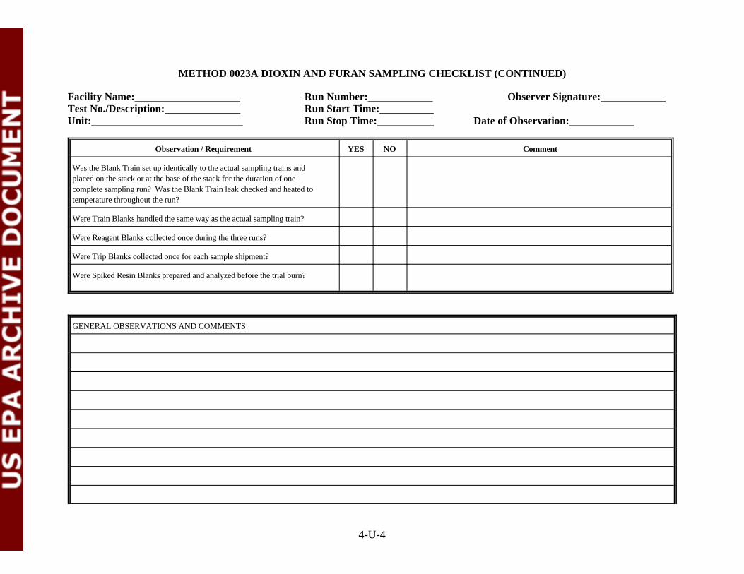
METHOD 0023A DIOXIN AND FURAN SAMPLING CHECKLIST (CONTINUED)
Facility Name: Run Number: Observer Signature: Test No./Description: Run Start Time: Unit: Run Stop Time: Date of Observation:
Observation / Requirement YES NO Comment
4-U-4
Was the Blank Train set up identically to the actual sampling trains andplaced on the stack or at the base of the stack for the duration of onecomplete sampling run? Was the Blank Train leak checked and heated totemperature throughout the run?
Were Train Blanks handled the same way as the actual sampling train?
Were Reagent Blanks collected once during the three runs?
Were Trip Blanks collected once for each sample shipment?
Were Spiked Resin Blanks prepared and analyzed before the trial burn?
GENERAL OBSERVATIONS AND COMMENTS

METHOD 0023A DIOXIN AND FURAN SAMPLING CHECKLIST (CONTINUED)
Facility Name: Run Number: Observer Signature: Test No./Description: Run Start Time: Unit: Run Stop Time: Date of Observation:
4-U-5

1 REVERSE - TYPE PITOT TUBE 2 PROBE 3 THERMOCOUPLE 4 STACK WALL 5 MANOMETER 6 THERMOCOUPLE 7 FILTER HOLDER 8 THERMOCOUPLE 9 CHECK VALVE10 FLEXIBLE VACUUM LINE11 VACUUM GAUGE12 MAIN VALVE13 BY- PASS VALVE14 AIR-TIGHT PUMP15 DRY GAS METER16 THERMOCOUPLE17 ORIFICE18 MANOMETER19 RECIRCULATION PUMP20 COOLING WATER21 CONDENSER22 XAD-2 ADSORBENT TRAP23 THERMOCOUPLE
Figure 0023A. PCDD/PCDF Sampling Train
TO ATMOSPHERE
17
1815 14
16 1613
12 11
10
98
SILICA GEL
23
22
1920
21
HEATED AREA
6
7
5
4STACK GAS FLOW
3
2
1
3
2
1
ICE BATHHPLC WATER
EMPTYEMPTY
4-U-5

ATTACHMENT V
METHOD 0023A PCDD/PCDF SAMPLE RECOVERY CHECKLIST
(4 Sheets)

4-V-1
METHOD 0023A DIOXIN AND FURAN SAMPLE RECOVERY CHECKLIST
Facility Name: Run Number: Observer Signature: Test No./Description: Run Start Time: Unit: Run Stop Time: Date of Observation:
Observation / Requirement YES NO Comment
Was the sample train disassembled at the sample port location? If so, werethe openings of the test train components (probe, filter bell, resin trap,impinger train, etc.) sealed before being relocated to the recovery area? Werethe components sealed with Teflon tape or noncontaminating caps?®
Was particulate matter visible on the filter? If so, describe the appearance(color, particle size, etc.) in the Comment column.
Was there any evidence that particulate matter may have bypassed thefilter? If so, describe in the Comment column.
Was the filter recovered with tweezers and loose particulate inside the filterbell collected into the original petri dish? Was the petri dish sealed withTeflon tape?®
Was the filter recovered intact without loss of particulate?
Did the “front half” sample train recovery include: an acetone rinse followedby methylene chloride solvent rinses in triplicate while brushing of thenozzle, liner, front half of the filter bell inlet, optional cyclone, and a finalrinse of the brush?
Was a final rinse of the “front half” sample train components conductedusing toluene?
Were all of the “front half” rinses collected in labeled amber glass bottleswith Teflon -lined lids?®
Did the recovery personnel visually inspect the “front half” sample traincomponents after the final rinses?
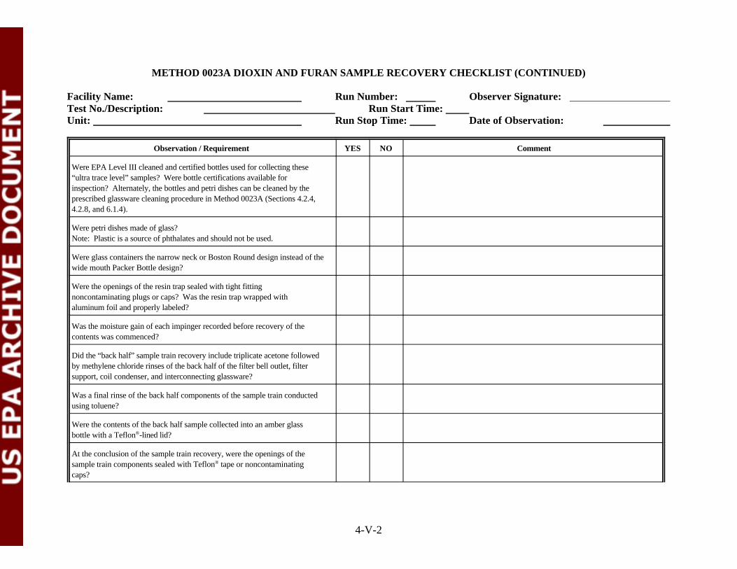
METHOD 0023A DIOXIN AND FURAN SAMPLE RECOVERY CHECKLIST (CONTINUED)
Facility Name: Run Number: Observer Signature: Test No./Description: Run Start Time: Unit: Run Stop Time: Date of Observation:
Observation / Requirement YES NO Comment
4-V-2
Were EPA Level III cleaned and certified bottles used for collecting these“ultra trace level” samples? Were bottle certifications available forinspection? Alternately, the bottles and petri dishes can be cleaned by theprescribed glassware cleaning procedure in Method 0023A (Sections 4.2.4,4.2.8, and 6.1.4).
Were petri dishes made of glass? Note: Plastic is a source of phthalates and should not be used.
Were glass containers the narrow neck or Boston Round design instead of thewide mouth Packer Bottle design?
Were the openings of the resin trap sealed with tight fittingnoncontaminating plugs or caps? Was the resin trap wrapped withaluminum foil and properly labeled?
Was the moisture gain of each impinger recorded before recovery of thecontents was commenced?
Did the “back half” sample train recovery include triplicate acetone followedby methylene chloride rinses of the back half of the filter bell outlet, filtersupport, coil condenser, and interconnecting glassware?
Was a final rinse of the back half components of the sample train conductedusing toluene?
Were the contents of the back half sample collected into an amber glassbottle with a Teflon -lined lid? ®
At the conclusion of the sample train recovery, were the openings of thesample train components sealed with Teflon tape or noncontaminating®
caps?
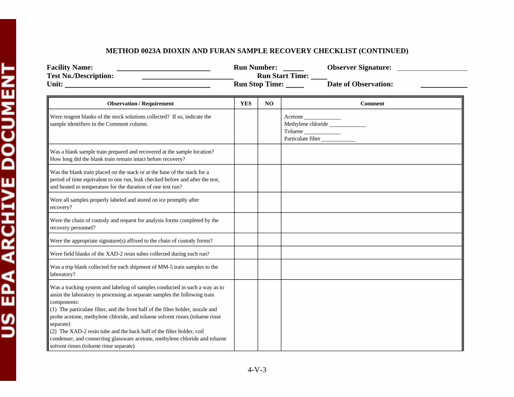
METHOD 0023A DIOXIN AND FURAN SAMPLE RECOVERY CHECKLIST (CONTINUED)
Facility Name: Run Number: Observer Signature: Test No./Description: Run Start Time: Unit: Run Stop Time: Date of Observation:
Observation / Requirement YES NO Comment
4-V-3
Were reagent blanks of the stock solutions collected? If so, indicate the Acetone sample identifiers in the Comment column. Methylene chloride
Toluene Particulate filter
Was a blank sample train prepared and recovered at the sample location? How long did the blank train remain intact before recovery?
Was the blank train placed on the stack or at the base of the stack for aperiod of time equivalent to one run, leak checked before and after the test,and heated to temperature for the duration of one test run?
Were all samples properly labeled and stored on ice promptly afterrecovery?
Were the chain of custody and request for analysis forms completed by therecovery personnel?
Were the appropriate signature(s) affixed to the chain of custody forms?
Were field blanks of the XAD-2 resin tubes collected during each run?
Was a trip blank collected for each shipment of MM-5 train samples to thelaboratory?
Was a tracking system and labeling of samples conducted in such a way as toassist the laboratory in processing as separate samples the following traincomponents:(1) The particulate filter, and the front half of the filter holder, nozzle andprobe acetone, methylene chloride, and toluene solvent rinses (toluene rinseseparate)(2) The XAD-2 resin tube and the back half of the filter holder, coilcondenser, and connecting glassware acetone, methylene chloride and toluenesolvent rinses (toluene rinse separate)

METHOD 0023A DIOXIN AND FURAN SAMPLE RECOVERY CHECKLIST (CONTINUED)
Facility Name: Run Number: Observer Signature: Test No./Description: Run Start Time: Unit: Run Stop Time: Date of Observation:
Observation / Requirement YES NO Comment
4-V-4
Was a tracking and labeling system used which was clearly understood bythe observer and would this system be clear to the receiving laboratory?
Was the recovery facility kept clean at all times?

METHOD 0023A DIOXIN AND FURAN SAMPLE RECOVERY CHECKLIST (CONTINUED)
Facility Name: Run Number: Observer Signature: Test No./Description: Run Start Time: Unit: Run Stop Time: Date of Observation:
4-V-5
GENERAL OBSERVATIONS AND COMMENTS

ATTACHMENT W
METHOD 0011 FORMALDEHYDE (ALDEHYDE & KETONE) SAMPLING CHECKLIST
(5 Sheets)

4-W-1
METHOD 0011 FORMALDEHYDE (ALDEHYDE & KETONE) SAMPLING CHECKLIST
Facility Name: Run Number: Observer Signature: Test No./Description: Run Start Time: Unit: Run Stop Time: Date of Observation:
Observation / Requirement YES NO Comment
Note: Acetone is a severe background contaminate for this train. Sinceacetone is required for use on any of the Method 0010 trains (semivolatiles,PCDD/PCDFs, PAHs, PCB, unspeciated mass) the Method 0011equipment should be handled in a completely separate area.
Did the train components appear to be clean and were all glassware openingscovered with Teflon film, aluminum foil, or noncontaminating caps before®
the train was assembled?
Was the train assembled by personnel in a manner that minimizedcontamination potential?
Were the first two impingers charged with 100 mLs each of the acidifiedDNPH solution?
Was the third impinger left empty during testing?
Was the train constructed of the components and materials identified inMethod 0011 (See Figure 0011: nozzle, heated probe, four impingers,control console, etc.)?
Were the dry gas meter, thermocouples, nozzle, and critical orifice devices Dry gas metercalibrated prior to the test? If yes, provide the calibration dates in the ThermocouplesComment column. If available, attach a copy of the calibration records. Critical orifice
Nozzle
Were weather conditions adverse to sampling (rain, snow, etc.)? If so,describe the measures taken to protect the sampling equipment in theComment column.
Was the sampling area (for example, the platform) kept clean and orderlyduring the run?
Were the traverse sample points determined in accordance with Method 1?
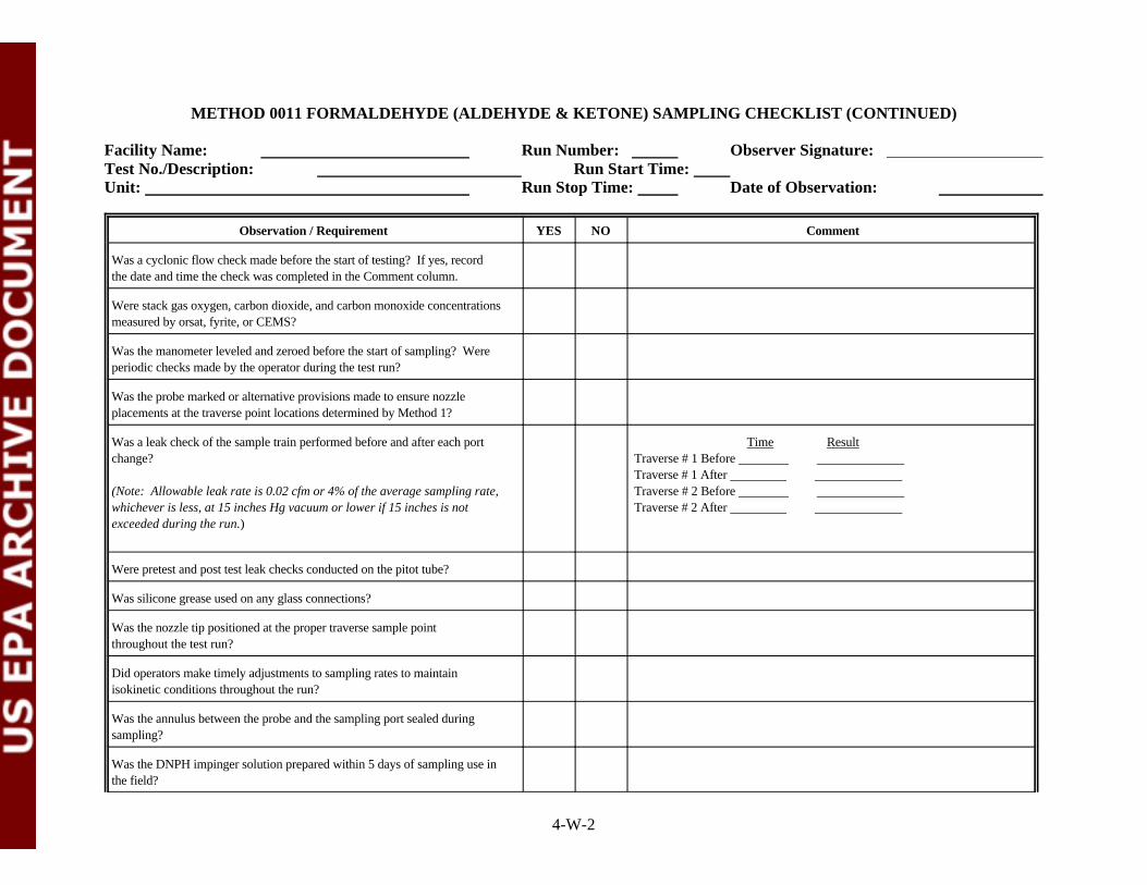
METHOD 0011 FORMALDEHYDE (ALDEHYDE & KETONE) SAMPLING CHECKLIST (CONTINUED)
Facility Name: Run Number: Observer Signature: Test No./Description: Run Start Time: Unit: Run Stop Time: Date of Observation:
Observation / Requirement YES NO Comment
4-W-2
Was a cyclonic flow check made before the start of testing? If yes, recordthe date and time the check was completed in the Comment column.
Were stack gas oxygen, carbon dioxide, and carbon monoxide concentrationsmeasured by orsat, fyrite, or CEMS?
Was the manometer leveled and zeroed before the start of sampling? Wereperiodic checks made by the operator during the test run?
Was the probe marked or alternative provisions made to ensure nozzleplacements at the traverse point locations determined by Method 1?
Was a leak check of the sample train performed before and after each port Time Resultchange? Traverse # 1 Before
(Note: Allowable leak rate is 0.02 cfm or 4% of the average sampling rate, Traverse # 2 Before whichever is less, at 15 inches Hg vacuum or lower if 15 inches is not Traverse # 2 After exceeded during the run.)
Traverse # 1 After
Were pretest and post test leak checks conducted on the pitot tube?
Was silicone grease used on any glass connections?
Was the nozzle tip positioned at the proper traverse sample pointthroughout the test run?
Did operators make timely adjustments to sampling rates to maintainisokinetic conditions throughout the run?
Was the annulus between the probe and the sampling port sealed duringsampling?
Was the DNPH impinger solution prepared within 5 days of sampling use inthe field?
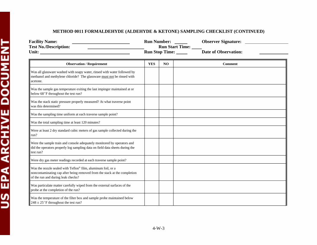
METHOD 0011 FORMALDEHYDE (ALDEHYDE & KETONE) SAMPLING CHECKLIST (CONTINUED)
Facility Name: Run Number: Observer Signature: Test No./Description: Run Start Time: Unit: Run Stop Time: Date of Observation:
Observation / Requirement YES NO Comment
4-W-3
Was all glassware washed with soapy water, rinsed with water followed bymethanol and methylene chloride? The glassware must not be rinsed withacetone.
Was the sample gas temperature exiting the last impinger maintained at orbelow 68EF throughout the test run?
Was the stack static pressure properly measured? At what traverse pointwas this determined?
Was the sampling time uniform at each traverse sample point?
Was the total sampling time at least 120 minutes?
Were at least 2 dry standard cubic meters of gas sample collected during therun?
Were the sample train and console adequately monitored by operators anddid the operators properly log sampling data on field data sheets during thetest run?
Were dry gas meter readings recorded at each traverse sample point?
Was the nozzle sealed with Teflon film, aluminum foil, or a®
noncontaminating cap after being removed from the stack at the completionof the run and during leak checks?
Was particulate matter carefully wiped from the external surfaces of theprobe at the completion of the run?
Was the temperature of the filter box and sample probe maintained below248 ± 25EF throughout the test run?

METHOD 0011 FORMALDEHYDE (ALDEHYDE & KETONE) SAMPLING CHECKLIST (CONTINUED)
Facility Name: Run Number: Observer Signature: Test No./Description: Run Start Time: Unit: Run Stop Time: Date of Observation:
Observation / Requirement YES NO Comment
4-W-4
Was the sampling rate kept at or below 0.75 meters /hour? Higher sampling3
rates cause loss of scrubbing efficiency in the DNPH and cause carry over ofthe impinger contents.
Did protracted or frequent “holds” occur during the sampling run? If so,describe the apparent cause and duration in the Comment column.
Inspect the field data sheets. Are they clear and completely filled out?
Was a Train Blank set up, leak checked and heated to temperature throughone complete sampling run of the trial burn?
Were Field Blanks collected during the trial burn?
Were Train Blanks handled the same way as the actual sampling train?
Were Reagent Blanks collected once during the three runs? DNPH impinger solution Methylene chloride Deionized water
Were Trip Blanks collected once for each sample shipment?
Were Field Spikes collected during the trial burn? Were field spikes appliedto DNPH impinger solution according to the Trial burn Plan?
METHOD 0011 FORMALDEHYDE (ALDEHYDE & KETONE) SAMPLING CHECKLIST (CONTINUED)
Facility Name: Run Number: Observer Signature: Test No./Description: Run Start Time: Unit: Run Stop Time: Date of Observation:
4-W-5
GENERAL OBSERVATIONS AND COMMENTS
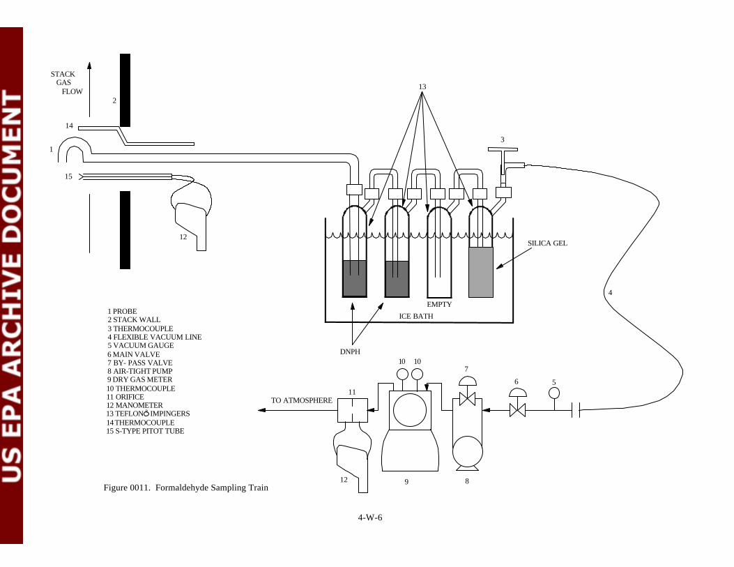
1 PROBE 2 STACK WALL 3 THERMOCOUPLE 4 FLEXIBLE VACUUM LINE 5 VACUUM GAUGE 6 MAIN VALVE 7 BY- PASS VALVE 8 AIR-TIGHT PUMP 9 DRY GAS METER 10 THERMOCOUPLE 11 ORIFICE 12 MANOMETER 13 TEFLON R IMPINGERS 14 THERMOCOUPLE 15 S-TYPE PITOT TUBE
Figure 0011. Formaldehyde Sampling Train
TO ATMOSPHERE
12 9 8
10 107
6 5
4
31
DNPH
ICE BATH
11
EMPTY
13
2
14
15
12
STACK GAS FLOW
SILICA GEL
4-W-6

ATTACHMENT X
METHOD 0011 FORMALDEHYDE (ALDEHYDE & KETONE) SAMPLE RECOVERYCHECKLIST
(4 Sheets)

4-X-1
METHOD 0011 FORMALDEHYDE (ALDEHYDE & KETONE) SAMPLE RECOVERY CHECKLIST
Facility Name: Run Number: Observer Signature: Test No./Description: Run Start Time: Unit: Run Stop Time: Date of Observation:
Observation / Requirement YES NO Comment
Note: The two DNPH impinger contents and rinses are to be analyzedseparately from these trains in order to assess breakthrough. Carry over ofthe contents from the first impinger to the second should be avoided or theassessment will be invalid. Moisture knockout impingers or additionalDNPH impingers may be added at the front of the train to prevent carryover.
Was the sample train disassembled at the sample port location? If so, werethe openings of the test train components (probe, filter bell, resin trap,impinger train, etc.) sealed before being relocated to the recovery area? Werethe components sealed with Teflon tape or noncontaminating caps?®
Were wash bottles made of Teflon or glass? Polyethylene wash bottles orplastic should not be used.
Did the “front half” sample train recovery include: methylene chloridesolvent rinses in triplicate while brushing of the nozzle and liner, and a finalrinse of the brush?
Were the fluid levels on the sample bottles marked in order to demonstratethat sample contents were not lost during shipments to the laboratory?
Were all of the “front half” rinses collected in labeled amber glass bottleswith Teflon -lined lids?®
Did the recovery personnel visually inspect the “front half” sample traincomponents after the final rinses?
Were EPA Level III cleaned and certified bottles used for collecting these“ultra trace level” samples? Were bottle certifications available forinspection? Alternately, the bottles can be cleaned by the prescribedglassware cleaning procedure in Method 0011 (Section 5.4.1).

METHOD 0011 FORMALDEHYDE (ALDEHYDE & KETONE) SAMPLE RECOVERY CHECKLIST (CONTINUED)
Facility Name: Run Number: Observer Signature: Test No./Description: Run Start Time: Unit: Run Stop Time: Date of Observation:
Observation / Requirement YES NO Comment
4-X-2
Were glass containers the narrow neck or Boston Round design instead of thewide mouth Packer Bottle design?
Were the contents of the 1st DNPH impinger recovered into a separateamber glass bottle with a Teflon -lined lid?®
Were the contents of the 2nd and 3rd impingers recovered in a separateamber glass bottle with a Teflon lined lid?
Were the knockout impingers, DNPH impingers and connecting glasswarerinsed three times with deionized water followed by methylene chloride?
Was the moisture gain of each impinger recorded before recovery of thecontents was commenced?
At the conclusion of the sample train recovery, were the openings of thesample train components sealed with Teflon tape or noncontaminating®
caps?
Were sample containers sealed with Teflon tape prior to shipment to thelaboratory?
Were reagent blanks of the stock solutions collected? If so, indicate the Methylene chloride sample identifiers in the Comment column. DNPH solution
Deionized water
Was a blank sample train prepared and recovered at the sample location? How long did the blank train remain intact before recovery?
Was the blank train placed on the stack or at the base of the stack for aperiod of time equivalent to one run, leak checked before and after the test,and heated to temperature for the duration of one test run?
Were all samples properly labeled and stored on ice promptly afterrecovery?
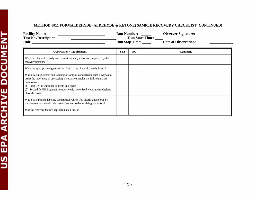
METHOD 0011 FORMALDEHYDE (ALDEHYDE & KETONE) SAMPLE RECOVERY CHECKLIST (CONTINUED)
Facility Name: Run Number: Observer Signature: Test No./Description: Run Start Time: Unit: Run Stop Time: Date of Observation:
Observation / Requirement YES NO Comment
4-X-3
Were the chain of custody and request for analysis forms completed by therecovery personnel?
Were the appropriate signature(s) affixed to the chain of custody forms?
Was a tracking system and labeling of samples conducted in such a way as toassist the laboratory in processing as separate samples the following traincomponents:(1) First DNPH impinger contents and rinses(2) Second DNPH impinger composite with deionized water and methylenechloride rinses
Was a tracking and labeling system used which was clearly understood bythe observer and would this system be clear to the receiving laboratory?
Was the recovery facility kept clean at all times?
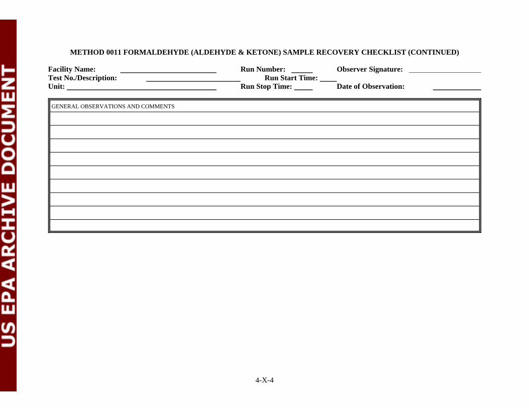
METHOD 0011 FORMALDEHYDE (ALDEHYDE & KETONE) SAMPLE RECOVERY CHECKLIST (CONTINUED)
Facility Name: Run Number: Observer Signature: Test No./Description: Run Start Time: Unit: Run Stop Time: Date of Observation:
4-X-4
GENERAL OBSERVATIONS AND COMMENTS

ATTACHMENT Y
HOW TO CONDUCT TRIAL BURN TEST OVERSIGHT REVIEW CHECKLIST
(13 Sheets)

4-Y-1
1.0 OVERVIEW OF TRIAL BURN OVERSIGHT
” Preparation Activities
” Conducting Field Activities
” Writing the TBO Report
” Stack gas sampling and recovery checklists (Attachments A through X)
” TBO Checklist (Attachment Y)
2.0 PREPARATION ACTIVITIES
Complete the following tasks before arriving at the facility to conduct trial burn oversight:
” Review TBP
” Review RBP
” Review QAPP
” Prepare a site-specific HSP
” Collect specific checklists to be completed on site
” Gather appropriate health and safety equipment
2.1 REVIEWING THE TRIAL BURN PLAN AND QUALITY ASSURANCE PROJECTPLAN
” General facility information
” Proposed stack gas sampling procedures
” Proposed waste feed and process residuals sampling procedures
2.1.1 Gathering General Facility Information
” Facility name
” Facility contact
” Facility address
” Facility telephone number
” U.S. EPA Facility Identification Number
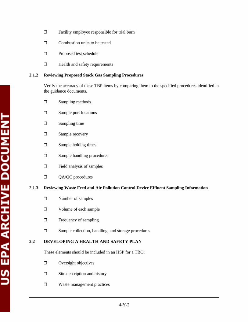
4-Y-2
” Facility employee responsible for trial burn
” Combustion units to be tested
” Proposed test schedule
” Health and safety requirements
2.1.2 Reviewing Proposed Stack Gas Sampling Procedures
Verify the accuracy of these TBP items by comparing them to the specified procedures identified inthe guidance documents.
” Sampling methods
” Sample port locations
” Sampling time
” Sample recovery
” Sample holding times
” Sample handling procedures
” Field analysis of samples
” QA/QC procedures
2.1.3 Reviewing Waste Feed and Air Pollution Control Device Effluent Sampling Information
” Number of samples
” Volume of each sample
” Frequency of sampling
” Sample collection, handling, and storage procedures
2.2 DEVELOPING A HEALTH AND SAFETY PLAN
These elements should be included in an HSP for a TBO:
” Oversight objectives
” Site description and history
” Waste management practices

4-Y-3
” Waste types and characteristics
” Hazards of concern
” Summary of hazardous substances
” Personal protective equipment
” Site personnel and responsibilities
” Emergency contacts
” Medical emergency
” Site map
3.0 CONDUCTING FIELD ACTIVITIES
The following specific field activities are conducted during a trial burn oversight:
” Conducting a pre-test meeting
” Conducting a pre-test facility survey
” Reviewing equipment calibration records
” Observing stack sampling
” Observing waste feed and APCS sampling
” Observing process operations
” Observing sample recovery
” Collecting trial burn test information
” Conducting daily meetings
” Compiling field documentation
” Observing audit gas sampling
3.1 CONDUCTING A PRE-TEST MEETING
” Explain the role of the oversight team to the trial burn personnel.
” Identify the individuals responsible for stack testing, waste feed sampling, APCSsampling, waste feed spiking, and recording process operating data.
4-Y-4
” Determine the schedule and plan for the trial burn testing.
” Identify any deviations from the SOPs indicated in the TBP or RBP
3.2 CONDUCTING A PRE-TEST FACILITY SURVEY
” Examine the unit to be tested and observe general process operating procedures.
” Inspect the APCSs associated with the unit to be tested and observe general operatingprocedures.
” Identify the stack gas, waste feed, and APCS effluent sampling areas.
” Whether the stack includes a rain hat or an obstruction to the flow of the gas
” Sketch the stack gas sampling location.
” Examine the sampling platform or scaffold.
” Match the sampling trains with the appropriate sampling ports and become familiar withthe order the trains will be employed.
” Inspect the stack gas sample recovery area and the field laboratory, if any.
” Determine the method and location of sample storage and labeling procedures.
” Identify persons responsible for monitoring process operating conditions and recordingthem at regular intervals.
” Identify the stack sampling personnel and their individual responsibilities.
” Identify the waste feed and APCS sampling personnel and their individual responsibilities.
3.3 REVIEWING EQUIPMENT CALIBRATION RECORDS
” Stack sampling equipment
” Feed spiking equipment
” Facility process control equipment
” CEMS
” Sampling methods
3.3.1 Reviewing Stack Sampling Equipment Calibration Records
” Pitot tubes

4-Y-5
” Differential pressure gauges
” Temperature indicators
” Dry gas meters
” Probe nozzles
” Rotameters
” Barometer
3.3.2 Reviewing Feed Spiking Equipment Calibration Records
” Pump and flow meter calibration records
” Pump and flow meter maintenance procedures
” Certificates of analysis for spiking chemicals
3.3.3 Reviewing Process Control Equipment Calibration Records
” Waste feed flow meters
” Atomization air pressure transmitters
” Pyrometers
” Differential pressure gauges across APCSs
” pH meters
” Oxidation and reduction potential meters
” Integral orifice meters
” Thermocouples and temperature indicators
3.3.4 Reviewing Continuous Emission Monitoring System Calibration Records
” Latest CEMS certification report
” Automatic daily calibration records
” Periodic manual calibration records
” Certificates of analysis of calibration gases

4-Y-6
3.3.5 Reviewing Field Laboratory Instrumentation Calibration Records
” Certificates of analysis
” Calibration records
” Maintenance procedures
3.4 OBSERVING STACK SAMPLING ACTIVITIES
” Are the sample ports properly cleaned before the test run to minimize the chance ofsampling deposited material?
” Do the probe and filter heating systems measure up to 120 ± 14 C or 248 ± 25 F beforeN N
the sampling begins?
” Are the probe and pitot tube positioned to point directly into the direction of stack gasflow?
” Are the openings around the probe and port hole blocked off during sampling to prevent anunrepresentative dilution of the gas stream?
The following specific sampling issues that should be carefully evaluated during a trial burn:
” Sampling port location
” Cyclonic flow check
” Traverse point calculations
” Sampling train assembly
” Leak checks prior to sampling
” Sampling train temperatures
” Field data logsheet
” Leak checks during sampling
” Sampling train disassembly
” Sampling checklists
3.4.1 Reviewing Sampling Port Location
” Stack diameter

4-Y-7
” Distance from sampling port to the nearest disturbance in upstream and downstreamdirections
” Process unit diagram
3.4.2 Reviewing Cyclonic Flow Measurements
” Cyclonic flow check data sheet
” Cyclonic flow calculations
3.4.3 Traverse Point Location
” Traverse point calculation sheet
3.4.4 Reviewing Sampling Train Assembly
” Availability of clean area for train assembly to prevent any contamination
” Proper probe markings for traversing within the stack
” Use of correct amount of reagents in the impingers
” Storage of sorbent traps at below 20 CN
” Use of proper connectors and sealants
” Proper assembly of filter in the filter holder
3.4.5 Observing Leak Checks Prior To Sampling
” Visible breakage of glass components (visual inspection)
” Leak in Pitot tube
” Leak in fully assembled sampling train
3.4.6 Observing Sampling Train Temperatures
” Thermocouple locations
” Proper condenser operation
” Ice in the impinger box
3.4.7 Observing the Field Data Logsheet
” Number of sampling ports
4-Y-8
” Number of traverse points
” Field data sheet
3.4.8 Observing Leak Checks During Sampling
” Field data sheet
3.4.9 Observing Sampling Train Disassembly
” Was the probe nozzle allowed to touch the stack wall or the platform?
” Was a final leak check conducted?
” Were the train components disassembled without any breakage or loss of sample?
” Were the train components properly capped, or sealed and labeled, before they weretransported to the sampling recovery area?
3.4.10 Completing Stack Sampling Checklists
” Method-specific checklists
3.5 OBSERVING WASTE FEED AND AIR POLLUTION CONTROL DEVICE EFFLUENTSAMPLING
” Whether the liquid in the sampling line was drained long enough before a sample wascollected
” Whether there are any visible air bubbles in the VOA vials
” Whether the samples are collected in accordance with the procedures specified in theapproved TBP, RBP, and QAPP and at the specified frequency
” Whether logsheets—showing date, time, run number, and sampler name—are completedfor each sample
” Whether sample containers are labeled—showing date, time, and identificationnumber—with a permanent marker pen
” Whether sample containers are handled and stored in accordance with the proceduresspecified in the approved TBP and QAPP
” Whether sample traceability and chain-of-custody records are being initiated andmaintained for each sample

4-Y-9
3.6 OBSERVING PROCESS OPERATION ACTIVITIES
” Process
” Combustion chamber temperature” Combustion gas temperature” Combustion chamber atomization and burner pressure” Combustion gas velocity” Excess air flow rate” Kiln rotational speed” CO concentration” O concentration2
” Total hydrocarbon concentration” Unit production rates
” Waste feed
” Feed rates” Chlorine input rates” Ash loading rates” Feed spiking compound rates” Atomization fluid pressure” Combustion chamber atomization and burner pressure
” Residue generation rates
” Bottom ash ” Fly ash ” Scrubber mud and solid residue
” Cyclone
” Pressure drop” Inlet temperature
” Dry scrubber
” Reagent flow rate” Atomizer rotational speed” Atomizer nozzle pressure” Inlet temperature” Outlet temperature
” Baghouse
” Pressure drop” Inlet temperature

4-Y-10
” Electrostatic precipitator
” Voltage” Current” Sparking rate” Flue gas flow rate
” Mist Eliminator
” Pressure drop
” Quencher
” Exit temperature” Water flow rate
” Packed tower scrubber
” Pressure drop” Liquid flow rate” Effluent pH
” Venturi scrubber
” Pressure drop” Liquid flow rate” Effluent pH” Gas-to-liquid flow rate ratio” Scrubbing reagent concentration” Scrubbing reagent flow rate” Maximum solids content in effluent
” Whether the data acquisition recorder (DAR) is a digital or an analog system
” Whether the digital readout agrees closely with the value on the strip chart recorder
” Whether the process operating conditions are close to the operating conditions specified inthe approved TBP or RBP
” Whether there is a way of cross-checking the flow rate on the basis of the volume changein the feed tank; if yes, do the flow rates agree closely (± 10 percent)?
3.7 OBSERVING SAMPLE RECOVERY
” Reagents used and number of rinses with each reagent
” Whether the samples are recovered in accordance with the procedures specified in theapproved TBP or RBP
4-Y-11
” Whether the liquid levels on the sample containers are clearly marked with a permanentmarker pen
” Whether the sample labels—showing identification number, date, and time—are affixedfirmly to the sample containers
” Whether sample identification number logsheet and chain-of-custody records are filled outfor each sample
” Whether sample containers are sealed and packaged securely, and chilled on ice in icechests or coolers for transportation
3.8 COLLECTING TRIAL BURN TEST INFORMATION
” Whether the gas temperatures at different locations in the sampling train, during the trialburn test are consistently within the ranges indicated in the specific test methods
” Whether the volumes of the stack gas samples collected remained consistently within theranges indicated in the specific test methods
” Whether the isokinetic sampling variations are within ±10 percent of the isokineticsampling rate
” Whether all sampling trains have passed the final leak checks
” Whether the process operating conditions maintained during the trial burn test conformwith the process conditions in the approved TBP or RBP
” Whether the waste feed and APCS effluent samples are collected in conformance with theprocedures specified in the approved TBP or RBP
3.9 CONDUCTING DAILY MEETINGS
During the daily meetings, the oversight team should summarize the following:
” Trial burn test runs planned for the day
” Major changes to or deviations from the approved TBP or RBP
” Problems encountered and their resolution
” Progress and completion schedule of the trial burn
3.10 CONDUCTING FIELD DOCUMENTATION ACTIVITIES
Documentation of field activities should include the following:
” Process operating parameters for each run
4-Y-12
” General impressions of stack sampling activities
” General impressions of stack sample recovery activities
” General impressions of waste feed and APCS sampling activities
” Deviations from and changes to the approved TBP or RBP
Photodocumentation should include the following:
” Combustion unit being tested
” Stack showing any obstructions to the flow of stack gases
” Waste feed storage tanks
” APCSs Units
” Location of stack sampling ports and sampling platform
” Location of CEMS probe
” Location of waste feed sampling
” Location of waste feed spiking
” Various stack sampling trains used during the trial burn
” Waste spiking system
” Waste feed and APCS sampling systems
” Modifications to or deviations from any standard sampling systems and proceduresidentified in the approved TBP or RBP
3.11 OBSERVING AUDIT GAS SAMPLING
” CEMS Relative Accuracy Test Audit
” CEMS Cylinder Gas Audit
” Volatile Organic Sampling Train (VOST).
” PCDDs and PCDFs Audit
4.0 PREPARING THE OVERSIGHT REPORT
” Overview of the TBO
4-Y-13
” Facility description
” Engineering description” Characterization of hazardous waste feed stream” Process operating conditions” CEMS
” Implementation of the trial burn
” Test conditions” Stack sampling” Waste feed sampling” Other sampling activities” Sample analysis” Process monitoring, control, and DAR” Trial burn completion schedule
” Field Observations
” Daily activities of the observers” General impressions of the observers” Deviations from approved TBP or RBP” Other problems and issues, and their resolution” Conclusions and recommendations


![Exposure Draft for the Hazardous Substances (Hazardous ... · 1. The EPA proposes to issue a Hazardous Substances (Hazardous Property Controls) Notice [the HPC Notice] that will set](https://static.documents.pub/doc/80x56/5f02b52b7e708231d4059c86/exposure-draft-for-the-hazardous-substances-hazardous-1-the-epa-proposes-to.jpg)