18 Plant Expansion Phase An Illustration of the Relative Ranking and HAZOP Analysis Methods for a Batch Process 18.1 Problem Definition Background The VCM plant has proved to be a successful enterprise. Five years into its operation, ABC's marketing group has recommended expanding the product line by making polyvinyl chloride (PVC) from vinyl chloride monomer (VCM). After ABC's business team reviews this recommendation, they decide to move forward with this venture. Tb expedite this expansion, ABC has chosen to buy the PVC technology from American Industrial Chemical Enterprises, Inc. (AICE), a major developer and licensor of PVC manufacturing technology. They are also recognized as a safety leader in the industry, and, after preliminary review of the PVC reactor design, ABC believes AICE's design and safety standards are as good as or better than ABC's. As with all the other units at the VCM plant, the business team and company management require that a hazard evaluation be performed on this new unit. ABC is particularly concerned because PVC production is a batch process, rather than a continuous one like most of ABC's other processes, and evidence has shown that batch processes are more prone to safety incidents. The business team asks ABC's process hazards analysis group to perform the HE study. ABC is considering two locations for the PVC reactor (Figure 18.1). Location #1 is near the VCM storage area. It is the preferred location because its proximity to the VCM supply would reduce piping and pumping costs. A negative aspect of site #1 is its proximity to the local highway: catastrophic accidents in the PVC reactor may threaten passing motorists. Also, the unit would be outdoors, which may pose a problem with freezing and plugging, since the PVC process uses water as a carrier. The second site being considered is near the VCM purification area. This location is an ample distance from the public. Also, the reactor could be located in an existing heated building, thus reducing the likelihood of freezing and plugging problems. However, PVC reactor accidents may threaten personnel in the plant's administrative offices.
Transcript
18Plant Expansion Phase
An Illustration of the Relative Ranking andHAZOP Analysis Methods for a Batch Process
18.1 Problem Definition
Background
The VCM plant has proved to be a successful enterprise. Five years into itsoperation, ABC's marketing group has recommended expanding the product line bymaking polyvinyl chloride (PVC) from vinyl chloride monomer (VCM). After ABC'sbusiness team reviews this recommendation, they decide to move forward with thisventure. Tb expedite this expansion, ABC has chosen to buy the PVC technologyfrom American Industrial Chemical Enterprises, Inc. (AICE), a major developer andlicensor of PVC manufacturing technology. They are also recognized as a safetyleader in the industry, and, after preliminary review of the PVC reactor design, ABCbelieves AICE's design and safety standards are as good as or better than ABC's.
As with all the other units at the VCM plant, the business team and companymanagement require that a hazard evaluation be performed on this new unit. ABCis particularly concerned because PVC production is a batch process, rather than acontinuous one like most of ABC's other processes, and evidence has shown thatbatch processes are more prone to safety incidents. The business team asks ABC'sprocess hazards analysis group to perform the HE study.
ABC is considering two locations for the PVC reactor (Figure 18.1). Location#1 is near the VCM storage area. It is the preferred location because its proximityto the VCM supply would reduce piping and pumping costs. A negative aspect ofsite #1 is its proximity to the local highway: catastrophic accidents in the PVCreactor may threaten passing motorists. Also, the unit would be outdoors, whichmay pose a problem with freezing and plugging, since the PVC process uses wateras a carrier.
The second site being considered is near the VCM purification area. Thislocation is an ample distance from the public. Also, the reactor could be located inan existing heated building, thus reducing the likelihood of freezing and pluggingproblems. However, PVC reactor accidents may threaten personnel in the plant'sadministrative offices.
In addition to the two locations, ABC is also considering using adecommissioned reactor vessel it has in storage. This vessel, while only designed toa 150-psig pressure, is adequate for use as the PVC reactor (the operating pressureof the PVC reactor is 75 psig). However, AICE has recommended a reactor with a250-psig design pressure.
Available Resources
While ABC has some experience producing VCM, they have no experienceproducing PVC. AICE, however, has a wealth of experience in this area. Inparticular, they can provide the following information for ABC's HE study:
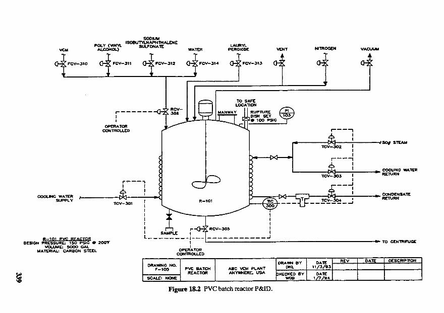
Typical P&IDs (Figure 18.2)Design specificationsPFDsOperating experienceHE studies on PVC technologyOperating proceduresAlarm setpoints and interlock descriptionsMSDSs of all materials in the PVC processEmergency response plan
In addition, AICE offers to supply ABC with one of its PVC process designersfor the hazard evaluation.
Selection of Hazard Evaluation Techniques
Mr. Dennis, of ABC's process hazards analysis group, is assigned to supervisethe HE study of the new PVC production process. After an initial review of thePVC reactor design, Mr. Dennis determines that two studies are needed: one HEstudy to help determine where the PVC reactor should be sited, and another toexamine the process safety hazards associated with the unit. Only the PVC reactorposes a significant siting concern because of its large VCM inventory; after the VCMis converted to PVC, the material presents a minimal hazard.
For the siting issue, Mr. Dennis quickly narrows his choices of HE methods toPHA and relative ranking. These techniques are selected because they focus on boththe equipment at hand and on other equipment and buildings in the area. Tb selectfrom among the siting alternatives, Mr. Dennis decides he needs a more definitiveresult than the qualitative ranking that a PHA normally provides. With this in mind,he chooses the Relative Ranking method, which gives a "hazard score" for eachsiting location.
The detailed HE study of the PVC unit should cover a broad range of hazards.Thus, Mr. Dennis decides that What-If Analysis, FMEA, HAZOP Analysis, andChecklist Analysis methods may be applicable. Not having a good checklist for thisnew technology, Mr. Dennis rules out this method. (Mr. Dennis has somegeneralized process hazard checklists, but he is not comfortable using them on atechnology unknown to him.) Of the remaining choices, Mr. Dennis believes theHAZOP Analysis method will work best because the guide word technique can easilybe applied to batch procedures. Thus, he chooses the HAZOP Analysis method.
VACUUMNITROGENVENTLAURYLPEROXIDEWATER
SODIUMISOBUTYLNAPHTHALENE
SULFONATEPOLY (VINYLALCOHOL)VCM
OPERATORCONTROLLED
MANWAY
TO SAFELOCATION
RUPTURE.DISK SET>• 100 PSC
STEAM
COOLING WATERRETURN
CONDCNSATERETURNCOOLING WATERSUPPLY
TO CENTRIFUGE
DESCRIPTIONDATEREVDATE11/3/03
DATE1/7/04
DRAWN BYDKL
ЬНЕСКЕО BYГ WCB
ABC VCM PLANTANYWHERE, USA
PVC BATCHREACTOR
DRAWING NO.F-105
SCALE: NONE
SAMPLE
OPERATORCONTROLLED
Figure 18.2 PVC batch reactor P&ID.
R—1O1 PVC REACTORDESIGN PRESSURE: 150 PSG 9 200T
VOLUME: 5000 GALMATERIAL: CARBON STEEL
TCV-301 R-101
RCV-3O5
TCV-302
TCV-3O3
TCV-3O4
Study Preparation
Relative Ranking. Mr. Dennis chooses to use the Dow Fire and Explosion Index(F&EI) Hazard Classification Guide in his relative ranking HE study. Tb perform theranking, he needs a plot plan of the site, a PFD of the new unit, and Dow's F&EIGuide. He also needs an inventory of the flammable and/or toxic materials in thenew unit. Mr. Dennis obtains a plot plan with the proposed new unit locations fromthe Anywhere VCM plant. The remaining information is obtained from AICE. Mr.Dennis reviews this information and the Dow Guide to see if any additional data areneeded. He notes that the credit factors require information on process controlfeatures and fire protection, information that he does not have. He will obtain thisinformation through telephone interviews with AICE and Anywhere plant personnel.
HAZOP Analysis. As with other HAZOP Analyses he has led, Mr. Dennisselects appropriately, skilled personnel to participate in the review. Since most ofthe ABC personnel who will participate have little or no PVC production experience,Mr. Dennis focuses on obtaining people with related experience (polymer production,batch operations, etc.). He also decides that it is critical that an experienced AICEemployee participate in the study. The following skilled personnel,are selected forthe review:
Leader — A person experienced in leading a HAZOP Analysis. Mr.Dennis will be the leader.
Scribe — A person with a good understanding of technical terminologyand the ability to quickly and accurately record information.Ms. Selda Slough will fill this position.
Process — A person who is thoroughly familiar with the design of theEngineer process and how it responds to process transients. Mr.
Thurmand Plastic of AICE, who helped design the PVCreactor, will fill this position.
Operator — An experienced person who knows how operators detect andrespond to reactor upsets. ABC has no experiencedoperators for this reactor system. Mr. Jim Smith, who hasworked as a VCM plant operator for the past four years, willfill this position. Jim formerly worked for AICE on some oftheir batch reactors.
Safety — A person familiar with the safety features at the VCM plant.Expert Mr. Fred Scott, a chemical engineer with over 15 years of
experience at the Anywhere site (both at the chlorine and atthe VCM plant), will fill this position.
In preparation for the HAZOP meeting, Mr. Dennis, working with Mr. Plastic,divides the unit into sections. For each section, he defines a design intention: thefunction performed by that section and its normal operating parameters. Since it isa batch operation, the design intention of the sections may change throughout thebatch. Tb address this, Mr. Dennis leads the HAZOP Analysis of the batchprocedure and of the process equipment.
Next, Mr. Dennis notifies the team of the schedule and place for the HAZOPAnalysis. Mr. Dennis chooses the Anywhere plant site for the meeting, thus allowinghim to review the site for the new unit. (Mr. Dennis plans to complete the relativeranking before the HAZOP Analysis; the HAZOP Analysis visit will allow him todouble-check the siting and protection information he used in the relative ranking.)Included in the notification is a set of information provided by AICE (P&ID's,operating procedures, etc.) and the sections and intentions developed by Mr. Dennisand Mr. Plastic.
As a last step, Mr. Dennis asks Ms. Slough to prepare a blank HAZOP tableto use in the review. Ms. Slough records the HAZOP Analysis minutes in pencil ona blank HAZOP table.
1&2 Analysis Description
Relative Ranking
Mr. Dennis performs the relative ranking alone and then has his work reviewedby another member of the process hazards analysis group. Since the P VC reactor isthe only major unit with a significant inventory of flammable material, he selects thisvessel for the HE study. The batch reaction used to make PVC requires largevolumes of VCM and water. For simplicity (and to be conservative), he onlyconsiders the VCM in the batch reactor's mixture when performing the relativeranking (i.e., he does not take into account the lower ranking that may occur if wateris in the mixture).
Having reviewed the Dow F&EI Guide, Mr. Dennis summarizes much of theinformation needed for the ranking (Table 18.1). He also calls Mr. Scott (to discussthe safety features in place at the two proposed sites) and Mr. Plastic (to discuss
Tkble 18.1 PVC Reactor/Site Information
Volume: 5,000 galNormal Fill: 80%Mature: ~ 43%VCM, 56% Water,Operating Pressure: 75 psigRupture Disk Setting: 200 psig (HOutdoor Unit (Site #1) Indoor U
shutdown interlocks on the reactor). Based on these discussions, Mr. Dennisdetermines that the loss control credit factors that are part of the Dow Guide willbe about the same for both locations. He chooses to estimate these factors becausethey affect the damage estimate for an accident, and thus are a factor in the siteselection.
The Dow Guide describes a step-by-step procedure for estimating an F&Eindex and, subsequently, a radius of exposure for the different reactors. Incalculating the factors, Mr. Dennis:
1. Estimates the material factor (MF) for VCM. (VCM is listed in theGuide and Mr. Dennis locates its factor in the appropriate table.)
2. Estimates the general process hazard factor (F1). Following theinstructions in the Guide, Mr. Dennis determines penalties forexothermic chemical reactions, material handling, enclosed process unit,access, and drainage. Because site #2 is indoors and has fair-to-poordrainage, Mr. Dennis penalizes this PVC reactor more heavily than thereactor at site #1.
3. Estimates the special process hazard factor (F2). Again, Mr. Dennisfollows the Guide's instructions. He notes that the pressurecomponent of this factor changes slightly, depending on which reactorvessel is used. He also penalizes site #2 for its proximity to thecracking furnaces.
4. Estimates the unit hazard factor (F3), fire and explosion index, andradius of exposure. These calculations involve simple multiplicationand addition of MF, Fl, and F2. Note that Mr. Dennis calculates theF&EI twice for the site #2 cases because the unit hazard factor exceedsthe recommended cutoff of 8.0. Since Mr. Dennis only wants tocompare causes rather than use the specific values, he calculates theF&EI using his estimated unit hazard factor and the cutoff value of 8.0.
5. Estimates the loss control credit factor. Mr. Dennis gives additionalcredit to site #1 for drainage and to site #2 for the building sprinklersystem. Otherwise, both sites have the same credits. Credit values areselected in accordance with guide instructions.
Figures 18.3-18.10 at the end of this chapter summarize Mr. Dennis's calculations forthe two proposed PVC sites and the different reactors. Tbble 18.2 summarizes hisfindings. Using the estimated radius of exposure and the Anywhere VCM plant plotplan, Mr. Dennis then identifies the equipment and personnel most likely to sufferimpact should a fire or explosion occur in the PVC unit
HAZOP Analysis
As the HAZOP Analysis begins, Mr. Dennis introduces the team members andtheir areas of expertise. He then reviews the analysis schedule. Normally, Mr.Dennis would also review the HAZOP Analysis method with the team; however, all
Tkble 18.2 Relative Ranking Results for the Plant Expansion Phase
Option
Site #1, 150 psig
Site #1, 250 psig
Site #2, 150 psig
Site #2, 250 psig
F&E Index
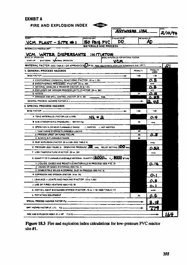
164
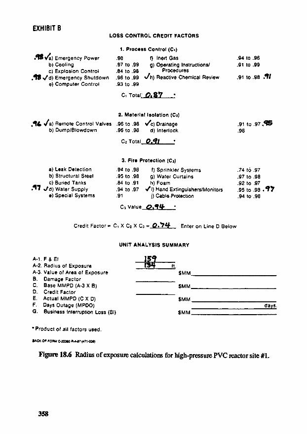
159
168(218)*
168(212)*
Loss ControlCredit lector
0.74
0.74
0.69
0.69
Radius of Exposure
(ft)
137
134
141(183)*
141(178)*
*Value assuming the unit hazard factor is not truncated at 8.0. The actual calculatedvalue is used.
of the team members, including Mr. Plastic, have previously participated in HAZOPAnalyses. After discussing the objectives of the HAZOP Analysis, Mr. Dennis asksMr. Plastic to explain the PVC production process.
Mr. Plastic — The PVC production process is relatively straightforward(see Figure 18.11, at the end of this chapter). Tb begin, weprepare the PVC reactor for feeds according to procedure.Once the reactor is ready, we add process water, thedispersants, the monomer, and the initiator. The reactor isheated to 50° С to initiate the reaction. The pressure atthe beginning of PVC production is about 75 psig, but itfalls to around 7 psig when the conversion is complete.We then heat the reactor to drive off excess monomer, andfollow this step by dropping the reactor contents into thecentrifuge. In the centrifuge we remove excess water fromthe PVC. The PVC pellets are then conveyed by air to ahot air dryer, sieved to remove oversized panicles, andfinally stored.
Mr. Dennis — Thanks. Tb start the review, we have agreed to HAZOPthe batch procedure. Mr. Plastic, could you walk usthrough the details of the batch?
Mr. Plastic — Sure. Each of you has a copy of the batch procedure (seeTable 18.3), so I will just explain the reasoning behindeach step. First, we verify that all feed valves are closed tohelp ensure that we start with an empty reactor. Then wepull a vacuum on the reactor to minimize the oxygenconcentration in it, thus reducing the potential for creatinga flammable concentration in the gas phase. Next we fillthe reactor approximately half full with water, which actsas the suspension phase for the polymerization. After that
Tkble 183 PVC Batch Reactor Operating Procedure*
Step Description
1 Verify that all feed line valves to the PVC reactor are closed and reactoris empty
2 Open the vacuum line valve and reduce reactor pressure to 10 psi
3 Open the water line valve and add 2250 gal of water to the reactor (setwater flow totalizer)
4 Start the agitator
5 Close the vacuum line valve
6 Open the poly (vinyl alcohol) line valve and add 7 gal of poly (vinylalcohol). Open the sodium isobutylnaphthalene sulfonate line valve andadd 1 gal
7 Open the lauryl peroxide line valve and add 7 gal
8 Open the VCM line valve and add 1700 gal of monomer
9 Set the reactor temperature controller to 50°C and heat up the reactorfor about eight hr. Maintain reactor temperature at 50°C for eight hr
10 When the reactor pressure drops to 7.5 psig, open the vacuum line valvefor 15 minutes
11 Cool the reactor to 16°C (about six hr)
12 Open the nitrogen supply line valve and vent to atmospheric pressure
13 Open the discharge valve and drop the reactor contents into thecentrifuge
"Revised March 12, 1994.
Mr. Plastic(cont'd)
the agitator is started, the reactor is bottled up, anddispersants are added. Finally, we add lauryl peroxide, aninitiator, to the batch and then add the monomer. Withall the ingredients present, we raise the reactortemperature to 50 С (the reactor pressure will be about75 psig initially) with steam heating on the jacket,and maintain the temperature until about 90%conversion is reached. It takes about eight hours. Atthat point the pressure is about 7.5 psig. The vacuum lineis opened and the excess monomer is vented off andrecovered. Usually 5 minutes is all that is needed for thisstep, but we recommend 15 minutes for a margin of safety.After recovering excess monomer, the reactor is cooled;then the reactor is padded with nitrogen, vented, and thePVC/water mixture is dropped into the centrifuge to beginthe drying process.
Mr. Dennis
Mr. Smith
Mr. Plastic
Ms. Slough
Mr. Plastic
Mr. Dennis
Mr. Smith
Mr. Dennis
Mr. Scott
Mr. Dennis
Mr. Scott
Mr. Dennis
Mr. Plastic
— Okay. The first guide word is No. Applying this to thefirst batch step gives the deviation No Verification. Whatis the consequence of no verification of closed feed valves?
— If you ran the previous batch correctly, I wouldn't thinkanything would happen. But, if you didn't dump theprevious batch, you'll eventually overfill the reactor withwater. The reactor will be solid with PVC and water,which you back up into one of the chemical feed lines, thevacuum line, or the nitrogen line. That would be a terribleclean-up problem, but I don't see any safety consequences.
— I agree. However, that error would probably only forceyou to take longer in centrifuging and restarting the batch.On the other hand, if one of the chemical feed valves isopen, then you may add too much dispersant, which lowersproduct quality, or too much monomer, which could be afire hazard. Ibis problem exists even if the last batch wentthrough okay.
— I don't understand. Where is the fire hazard?
— If you have too much monomer, then you could havemonomer left in the batch after the recovery step. Theproblem arises when this monomer gets to the hot airdryer.
— What are causes for skipping step 1?
— Well, I'll point the finger at myself. An operator couldforget this step.
— Others? [None suggested] Safeguards?
— I'm sure we'll have extensive operator training beforestarting this process. Also, we'll require writtenprocedures for the batch.
— Any more safeguards? [None suggested] Actions?
— We should develop a checklist for the operator — a simpleone-page checkoff like this list you gave us. I also don'tsee any load cells or a level indicator on the reactor P&ID.Perhaps we should add (1) a level indicator so theoperator can catch a valve being open at the wrong timeand (2) a high level alarm.
— Ms. Slough, do you have that recommendation? [Nodsyes.]
— The water and monomer lines are the only big lines to thereactor. A level indicator and alarm may catch a problemwith these lines, but I doubt it will help with the otherfeeds.
Mr. Dennis
Mr. Scott
Mr. Dennis
Mr. Plastic
Mr. Dennis
Mr. Plastic
Ms. Slough
Mr. Dennis
Mr. Plastic
Mr. Dennis
Mr. Smith
Mr. Dennis
Mr. Scott
Mr. Plastic
— Wait a minute. We are already designing solutions. Let'sjust note that the operators need a way to positively verifyand acknowledge that the valves are closed and the reactoris empty. If there are no more ideas, let's move on.
— The flow meters on the feed lines would be a better way tocatch an open valve. That's what yo.u should alarm.
— I get the idea. Again, let's not attempt to design thesolution. Another possible No deviation is No Step; thatis, a written step prior to verification is needed. Is this thecase here? [Heads shake no.] Okay, do you think theHigh and Low guide words apply to step 1? [Team saysno.] How about Reversing the step sequence, doingsomething Other Than this step, or doing only Part Of thisstep?
— Reversing this Step would be checking the reactor first andthe valves second. That should be no problem. Doingonly Part Of the step or something Other Than this step isthe same as not doing step 1. You may have too muchdispersant, initiator, or monomer that could lead to poorproduct quality or a fire hazard in the dryer.
— What are the causes?
— I think the causes, safeguards, and actions we justsuggested apply again. [Others agree.]
— Let me read them back to you to be sure. [She reads themand team agrees they are okay.]
— I plan to cover the As Well As deviation as we cover thelater steps in the process. The next step is to reduce thereactor pressure to about 10 psi. Is there a step missingbetween steps 1 and 2? [Team agrees no.] What happensif this step is skipped?
— Then you will have air in the head space during the batch.That is a potential fire and explosion hazard.
— Causes?
— Operator error.
— What else? [Period of silence.] What about a failedvacuum system or a stuck valve on the vacuum line?
— Those make sense» although it seems as if that would bealarmed.
— The failure of the vacuum system would trigger an alarm,and the vacuum valve position is indicated in the controlroom. I guess you count those as safeguards. Anotherpossible cause is a faulty reactor pressure gauge.
Mr. Dennis
Mr. Plastic
Mr. Dennis
Mr. Plastic
Mr. Dennis
Mr. Plastic
Mr. Scott
Mr. Plastic
Mr. Dennis
Mr. Smith
Mr. Dennis
Mr. Smith
Mr. Dennis
Mr. Scott
Mr. Dennis
Mr. Smith
Ms. Slough
Mr. Dennis
— Safeguards?
— You've got the alarms and indicators I've just mentioned,and you've got the operator training mentioned earlier.
— Others? [None suggested] Actions? [None suggested]Okay, let's look at the High deviation. What's theconsequence of pulling too much vacuum?
— I don't think the vacuum system can pull the reactor downmuch lower than 4 psi.
— So, the potential exists to collapse the reactor. Ms.Slough, make a note in the recommendations to determinethe maximum vacuum capability of the vacuum system.
— Wait a minute. Although not rated for full vacuum, the250-psig reactor is large enough and has sufficient wallthickness to withstand full vacuum. I'm not sure about the150-psig reactor.
— It probably can take full vacuum, but we should check itout. By the way, that 10 psi, is it gauge or absolute?
— It's absolute. But I see your point. An operator could getit wrong. I guess an action is to update the procedure tofix this.
— Come on now — let's slow down or we'll get lost. Beforemaking recommendations, what are the causes of too muchvacuum?
— Operator error.
— Okay, but it's not always operator error. Jim, what else?
— Well, a bad pressure gauge on the reactor would possiblymislead an operator. Also, plugging is a commonproblem.
— Other causes? [None suggested.] Safeguards?
— Operator training. Once this reactor is up and running,I'm sure operators will know the amount of time it takesto get to 10 psia.
— Recommendations?
— Besides the things you have already said, it seems likeanother pressure gauge would help since pressure seemspretty important in this process. Plus, the second gaugemay reveal a plugging problem.
— Just a minute so I can catch up on these recommendations.
— Okay. Other recommendations? [Quiet.] What aboutTbo Little Vacuum?
Mr. Scott
Mr. Dennis
Mr. Plastic
Mr. Scott
Mr. Plastic
Mr. Dennis
Mr. Scott
Mr. Plastic
Mr. Scott
Mr. Dennis
Ms. Slough
Mr. Dennis
Mr. Plastic
— Well, I think you have the same things as with skippingthis step, only maybe not as bad.
— Do all of you agree? [Others nod approval] What if youReverse steps 1 and 2?
— If the last batch went through okay, no problem.Otherwise, if you have material left in the reactor, a leakyor open feed valve, or a leaky agitator seal, then you won'treach your 10 psia and you'll end up throwing away somematerials through the vacuum line. Since we pull excessmonomer out this way anyway, I don't see much more thanan economic penalty.
— What about removing the air from the reactor? Won't wehave the same consequence as the No Vacuum?
— Maybe. I don't know if we remove enough air in this caseto be okay or not. Maybe we should take a closer look atthis!
— Any other causes besides operational error for thedeviation? [None suggested.] Some safeguards are, again,operator training and the pressure gauge on the reactor.Others? [Nothing said.] Recommendations?
— Why doesn't this batch reactor have a PLC (programmablelogic controller) to sequence through the steps?
— That can certainly be done. I can only guess that ABCdidn't want the cost.
— I think we should recommend a PLC. We are barely intothis and it looks like there is plenty of room for operatorerror.
— Any more recommendations? [None.] Ms. Slough, areyou keeping up? [Nods yes.] Let's see. Part Of would bethe same as Low Vacuum. Is there anything an operatormight do Other Than open the vacuum line?
— There's no incentive for an operator to take any otheraction here, and there are no parallel reactors that mightbe evacuated by mistake.
— Okay. Let's look at As Well As. What if we do step 2 AsWell As one of the next steps?
— Pulling a vacuum As Well As feeding materials will resultin not evacuating the air as planned, and thus we have thefire hazard. If the vacuum line is open during the batch,you'll lose a lot of monomer and will probably lift therelief valve on the condenser for monomer recovery. Also,the reactor pressure will drop.
— You've got the same operator training factors as before, aswell as the pressure gauge on the reactor. There's noreason for the operator to take a shortcut like that.
— Recommendations?
— I'll reiterate my PLC recommendation.
This review continues until all the steps of the batch are examined. The teamthen evaluates each section of equipment in the new unit during normal operationto identify and evaluate any additional hazards. At the conclusion of the HAZOPAnalysis, Mr. Dennis thanks all the participants and reminds them that he will sendthem a HAZOP report for their review and comment in a few weeks.
183 Discussion of Results
Relative Ranking
The Relative Ranking method was used to estimate a radius of exposure foreach of the two proposed PVC unit sites. The F&EI calculations Mr. Dennisperformed showed an exposure radius of about 135 feet for site #1 and 140 feet (or180 feet using Mr. Dennis's unit hazard factor instead of the cutoff value) for site #2,regardless of which reactor vessel (the low pressure or the high pressure) was used.According to the plant's plot plan, the site #2 exposure zone encompasses othermajor equipment: the VCM purification columns. More importantly, the exposurezone for site #1 does not involve the VCM storage tanks. Large populations ofpeople are not affected at either site. The safety factors at either location are aboutequal. Thus, site #1 appears to be the better choice.
HAZOP Analysis
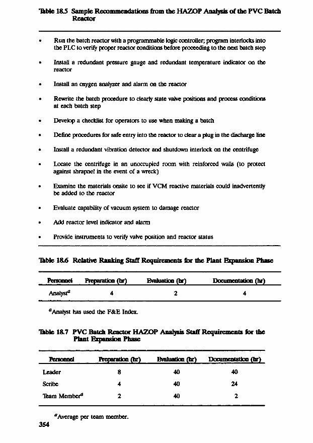
Tkble 18.4 at the end of this chapter illustrates some of the HAZOP Analysisresults. Ms. Slough generates the HAZOP table, transcribing her notes into a typedtable. Because the PVC reactor design had not previously been examined andbecause it was not designed to ABC's standards, the HAZOP team suggests anumber of improvements. Ikble 18.5 at the end of this chapter lists some of themore important recommendations.
1&4 Follow-Up
Relative Ranking
The Relative Ranking portion of the HE study was completed entirely by Mr.Dennis and reviewed by Ms. Deal (also with ABC's process hazards analysis group).The results, along with Mr. Dennis' recommendations, were transmitted to the VCMbusiness team for evaluation. The business team used these results to help themselect site #1 for the new PVC reactor.
HAZOP Analysis
Some unresolved issues remained following the HAZOP Analysis. These issueswere assigned to various team members to resolve. Mr. Dennis checked with thesemembers weekly until every issue was resolved. The recommendation for the PLCwas accepted and the team was later reassembled to perform an FMEA on the PLC.
Mr. Dennis, along with Ms. Slough, prepared a report of the HAZOP Analysis.The report described the scope of the review, who participated, what information(drawings, procedures, etc.) was used, and the findings of the team. This report wascirculated among team members for comment, updated by Mr. Dennis, and then sentto the VCM business team for evaluation. The business team was made responsiblefor following up on each recommendation. Using ABC's computerized trackingsystem, Mr. Chemist (of the business team) checked monthly on the implementationof the recommendations until all recommendations were completed.
1&5 Conclusions and Observations
Relative Ranking
The relative ranking HE was performed to determine which site should be usedfor the new PVC reactor. While the fire and explosion indexes for the two sitesproduced nearly the same results, the analysis still proved to be quite useful. Site #1was the business team's preference of the two sites; however, they were concernedwith putting the high pressure reactor near the VCM storage, the ethylene supplysystem, and the highway. Site #2, while more distant from large fuel supplies andthe highway, had the drawback of being close to the furnaces and the administrationbuilding. The relative ranking analysis showed, however, that a major fire andexplosion in the PVC reactor at site #1 should not significantly threaten theequipment, buildings, and roadways near the site. This was not true for site #2.Thus, the business team recommends site #1. The business team also notes that,provided it is adequately inspected and tested, the lower pressure reactor vesselshould be adequate for this service. The time required to perform the RelativeRanking is summarized in Ikble 18.6 at the end of this chapter.
HAZOP Analysis
The HAZOP Analysis proved to be a very important part of the HE studybecause the new technology, not designed or previously evaluated by ABC, was foundto have a number of safety deficiencies. The review team identified a number ofrecommendations that the business team should carefully consider with theacquisition of the new technology.
The HAZOP Analysis meetings went quite smoothly, both because Mr. Dennisis a highly experienced leader and because all the team members were experiencedand cooperative HAZOP participants. It is important to note that Mr. Plastic waskey to the success of the review. Without his depth of experience with the PVCprocess ABC was acquiring, the team would have struggled to understand the design.The time required to perform the HAZOP Analysis is summarized in Tkble 18.7 atthe end of this chapter.
ЪЫе1&4 Sample H AZOF Analysis Results for the PVC Reactor
P&mNo: E-101Procedure Dated: 3/12/94Meeting Date: 5/4/94Revision: 5Tbam: Mr. Dennis (Leader — Process Hazard Analysis), Ms. Slough (Anywhere VCM Plant), Mr. Smith (Anywhere VCM
Plant), Mr. Scott (AnywhereVCM Plant), Mr. Plastic (AICE)
ActionsSafeguardsConsequencesCausesDeviationItem
Number
1.0 PVC REACTOR BATCH - STEP 1: VERIFY ALL FEED LINE VALVES ARE CLOSED AND REACTOR IS EMPTY
Develop a batch checklist
Provide instruments toverify valve positions andreactor status
Add a reactor levelindicator and high levelalarm
Develop a batch checklist
Provide instruments toverify valve positions andreactor status
Add a reactor levelindicator and high levelalarm
Operator training
Written procedures
Operator training
Written procedures
Increased potential formaterial to leak intoreactor when air ispresent. Potential firehazard (monomer andair)
Increased potential formaterial to leak intoreactor when air ispresent. Potential firehazard (monomer andair)
Operator error —skips step
Operator error —skips step
No verification
Part ofverification
1.1
1.2
Table 1&4 (coet'd)
P&IDNo: Е-101Procedure Dated: 3/12/94Meeting Date: 5/4/94Revision: 5learn: Mr. Dennis (Leader — Process Hazard Analysis), Ms. Slough (Anywhere VCM Plant), Mr. Smith (Anywhere VCM
Plant), Mr. Scott (AnywhereVCM Plant), Mr. Plastic (AICE)
ActionSafeguardsComequencesGamesDeviationItem
Number
2.0 PVC REACTOR BATCH - STEP 2: OPEN THE VACUUM LINE VALVE AND REDUCE REACTOR PRESSURE TO10 PSI
Evaluate the capability ofthe vacuum system todamage the reactor
Revise the batchprocedure to make theunits clear (psia vs psig)
Install a second pressuregauge on the reactor
Operator training
"vWitten procedures
Vacuum system alarm
Pressure indicated incontrol room
Vacuum valve positionindicated in control room
Operator training
Reactor pressureindicated in control room
Potential flammable/explosive mixture inreactor head space
Potential flammable/explosive mixture inreactor head space
Potential flammable/explosive mixture inreactor head space
Potential large releaseof hot monomer tothe atmospherethrough the overheadcondenser relief valve
Potential fire hazard
Operator error —skips step
Vbcuum systemfailure
Vacuum valvesticks closed
Reactor pressuregauge fails — falselow
Operator error
Operator error
2.3 Lowevacuation
2.4 Reverse stepsland 2
2.5 Step 2 as wellas another step
Ikbtel&S Sample Recommendations from tbe HAZOP Analysis of the PVC BatchReactor
• Run the batch reactor with a programmable logic controller; program interlocks intothe PLC to verify proper reactor conditions before proceeding to the next batch step
• Install a redundant pressure gauge and redundant temperature indicator on thereactor
• Install an oxygen analyzer and alarm on the reactor
• Rewrite the batch procedure to clearly state valve positions and process conditionsat each batch step
• Develop a checklist for operators to use when making a batch
• Define procedures for safe entry into the reactor to clear a plug in the discharge line
• Install a redundant vibration detector and shutdown interlock on the centrifuge
• Locate the centrifuge in an unoccupied room with reinforced walls (to protectagainst shrapnel in the event of a wreck)
• Examine the materials onsite to see if VCM reactive materials could inadvertentlybe added to the reactor
• Evaluate capability of vacuum system to damage reactor
• Add reactor level indicator and alarm
• Provide instruments to verify valve position and reactor status
Tkble 18.6 Relative Ranking Staff Requirements for the Plant Expansion Phase
рамм a* ]%^PLANT PROCESS UNIT EVALUATED BY REVIEWED BYVCM PLAJJT - SITE a* I I ISO RStfl PVC I OP I AD
MATERIALS AND PROCESSMATERIALS IN PROCESS UNIT —--—---------———---—------———----—-—-——--—--—-———--—----—---—
VCM W4TER DISPEKSAHTS 1МГПЛГТО13STATE О* OPERATION . (BASIC MATERIALS) FOR MATERIAL FACTOR
START-UP SHUT-DOWN ^ORMAL OPERATION ^(L/AMATERIAL FACTOR (SEE TABLE I OR APPENDlCES^bR B) Note rcqu.femems when umt temperature over HO F> ^ I JJ7I1. GENERAL PROCESS HAZARDS PENALTY ''USED*
BASE FACTOR » | VOO | I~00A EXOTHERMIC CHEMICAL REACTIONS (FACTOR .30 to 1.25)В ENDOTHERMIC PROCESSES (FACTOR .20 to .40»С MATERIAL HANDLING & TRANSFER (FACTOR .25 to 1 OS)D ENCLOSED OR INDOOR PROCESS UNITS (FACTOR .25 to .90)E ACCESS \ "F DRAINAGE AND SPILL CONTROL (FACTOR .25 to .50) 6»l$.
GENERAL PROCESS HAZARDS FACTOR (F,) .2. SPECIAL PROCESS HAZARDS
BASE FACTOR ».
A TOXIC MATERIAL(S) (FACTOR 0.20 to 0.80) У^К * 2lВ SUB-ATMOSPHERIC PRESSURE ( 500 mm Hg»С OPERATION IN OR NEAR FLAMMABLE RANGE L! INERTED L NOT INERTED
1. TANK FARMS STORAGE FLAMMABLE LIQUIDS2 PROCESS UPSET OR PURGE FAILURE3 ALWAYS IN FLAMMABLE RANGE
D. DUST EXPLOSION (FACTOR .25 lo 2 00) (SEE TABLE II)E PRESSURE (SEE FIGURE 2) OPERATING PRESSURE «P psig RELIEF SETTING JU2O psig|F LOW TEMPERATURE (FACTOR .20 10 .30) j
G QUANTITY OF FLAMMABLE/UNSTABLE MATERIAL: QUANTITY tBOQOtbt HC« 8QQQ BTU/lb l
1 LIQUIDS. GASES AND REACTIVE MATERIALS IN PROCESS (SEE FIG. 3) j2 LIQUIDS OR GASES IN STORAGE (SEE F>G 4) '3 COMBUSTIBLE SOLIDS IN STORAGE. DUST IN PROCESS (SEE FIG 5)
H CORROSION AND EROSION (FACTOR .10 lo .75)I. LEAKAGE - JOINTS AND PACKING (FACTOR .10 to 1.50)J. USE OF FIRED HEATERS (SEE FIG. 6) jK. HOT OIL H£AT EXCHANGE SYSTEM (FACTOR .15 to 1.15) (SEE TABLE III)L ROTATING EQUIPMENT
SPECIAL PROCESS HAZARDS FACTOR <F()
UNIT HAZARD FACTOR (F, я F, F,)
FIRE AND EXPLOSION INDEX (F, * MF - F A El)
Figure 183 Fire and explosion index calculations for low-pressure PVC reactorsite#l.
EXHIBIT ВLOSS CONTROL CREDIT FACTORS
1. Process Control (Ct)•^8^а) Emergency Power .98 f) Inert Gas .94 to .96
b) Cooling .97 to .99 g) Operating Instructions/ .91 to .99c) Explosion Control .84 to .98 / Procedures
.^Sv/d) Emergency Shutdown .96 to .99 vlh) Reactive Chemical Review .91 to .98 . 1e) Computer Control .93 to .99
Ci Total O.V7 *
2. Material Isolation (C2)Лб\/а) Remote Control Valves .96 to .98 */c) Drainage .91 to .97 %^S
b) Dump/Blowdown .96 to .98 d) Interlock .98
C2 Total D.qi
3. Fire Protection (Сз)a) Leak Detection .94 to .98 f) Sprinkler Systems .74 to .97b) Structural Steel .95 to .98 g) Water Curtains .97 to .98c) Buried Tanks .84 to .91 h) Foam .92 to .97
• • I ч/d) Water Supply .94 to .97 J\) Hand Extinguishers/Monitors .95 to .98 • • •e) Special Systems .91 j) Cable Protection .94 to .98
C3 Value Q.94
Credit Factor = Ci X Cz X C3 « O*1?^ Enter on Line D Below
UNIT ANALYSIS SUMMARY
A - L F & E I \№A-2. Radius of Exposure BY ft.A-3. Value of Area of Exposure $MMB. Damage FactorC. Base MMPD (A-3 X B) $MMD. Credit FactorE. Actual MMPD (C X D) $MMF. Days Outage (MPDO) days.G. Business Interruption Loss (Bl) $MM
* Product of all factors used.
SACK OF РОЯМ 022ЭвО R.447 (4714Э6)
Figure 18.4 Radius of exposure calculations for low-pressure PVC reactor site #1.
EXHIBIT A
FIRE AND EXPLOSION INDEX -<ф>
[-яйшид 1ш g ;*UAN1 PROCESS UNIT EVALUATED BV PEvitwED B*VCM PLAMT •» SITE *l HBO RS>6 PVC. I DP ДО
MATERIALS AND PROCESSMATERIALS IN PROCESS UNIT " ~ " ~ . - • •
VCM WATER DlSPEgaAMTS ^MlTlATtoRSTATE Of OPERATION BASIC MATERiAuS» FOR MATERIAL «ACTOR
START-UP SHUT-DOWN ^^ORMAL OPERATION \/{*AAMATERIAL FACTOR {SEE TABLE I OR APPENDICESQPR B) Npie r«qu.»«m««t» WhCn un.i lempe-a^e ove' up F, _ | §1. GENERAL PROCESS HAZARDS PENALTY PyN
s
A
E
L
0
TY
BASE FACTOR ». i oo i ooA EXOTHERMIC CHEMICAL REACTIONS (FACTOR .30 to 1.25)В ENDQTHERMIC PROCESSES (FACTOR .20 to .40)С MATERIAL HANDLING 4 TRANSFER (FACTOR .25 to 1.05)D ENCLOSED OR INDOOR PROCESS UNITS (FACTOR 25 to .901E ACCESSF DRAINAGE AND SPILL CONTROL (FACTOR .25 to 50) Gils.
GENERAL PROCESS HAZARDS FACTOR (F,j — ,2. SPECIAL PROCESS HAZARDS
BASE FACTOR ».
A TOXIC MATERIAL(S) (FACTOR 0.20 10 0.80) WL в 3iВ SUB-ATMOSPHERIC PRESSURE ( 500 mm Hg>С OPERATION IN OR NEAR FLAMMABLE RANGE .Г INERTED L NOT INERTED
1 TANK FARMS STORAGE FLAMMABLE LIQUIDS2 PROCESS UPSET OR PURGE FAILURE3 A L W A Y S IN FLAMMABLE RANGE
D. DUST EXPLOSION (FACTOR .25 to 2 00) (SEE TABLE II)E. PRESSURE (SEE FIGURE 2) OPERATING PRESSURE 7S ps,g RELIEF SETTINGSlOOps 5F LOW TEMPERATURE (FACTOR .2010.30)
G QUANTITY OF FLAMMABLE/UNSTABLE MATERIAL: QUANTITY ISflQQiht HC* 8005вти IDl LIQUIDS. GASES AND REACTIVE MATERIALS IN PROCESS (SEE PIG. 3)2 LIQUIDS OR GASES IN STORAGE (SEE FiG *)3 COMBUSTIBLE SOLIDS IN STORAGE. OUST IN PROCESS (SEE PlG 5)
M. CORROSION AND EROSION (FACTOR .10 to .75)i. LEAKAGE - JOINTS AND PACKING (FACTOR .10 to 1.50)J. USE OF FIRED HEATERS (SEE FIG. 6)K. HOT OIL HEAT EXCHANGE SYSTEM (FACTOR .15 to 1.15) (SEE TABLE III)L. ROTATING EQUIPMENT I 5y
SPECIAL PROCESS HAZARDS FACTOR (F,) .. ^
UNIT HAZARD FACTOR (F, x F, Fj) _ . fr~
FIRE AND EXPLOSION INDEX (F, * MF - F i El)
Figure 18.5 Fire and explosion index calculations for high-pressure PVC reactorsite#l.
EXHIBIT ВLOSS CONTROL CREDIT FACTORS
1. Process Control (Ci)
Л&ча) Emergency Power .98 f) Inert Gas .94 to .96b) Cooling .97 to .99 g) Operating Instructions/ .91 to .99c) Explosion Control .84 to .98 Procedures
.18</d) Emergency Shutdown .96 to .99 vh) Reactive Chemical Review .91 to .98 Д!e) Computer Control .93 to .99
Ci Total ОЛ*1
2. Material Isolation (C2)
/14 Уа) Remote Control Valves .96 to .98 /c) Drainage .91 to .97 «Я5b) Dump/Blowdown .96 to .98 d) Interlock .98
C2 Total OAl
3. Fire Protection (Сз)
a) Leak Detection .94 to .98 f) Sprinkler Systems .74 to .97b) Structural Steel .95 to .98 g) Water Curtains .97 to .98c) Buried Tanks .84 to .91 h) Foam .92 to .97
Л7 s/d) Water Supply .94 to .97 У'О Hand Extinguishers/Monitors .95 to .98 . Уe) Special Systems .91 j) Cable Protection .94 to .98
Сз Value ОЛЬ *
Credit Factor = Ci X Cz X Сз « О**Ш Enter on Line D Below
UNIT ANALYSIS SUMMARY
A-1.F&EI IS4?A-2. Radius of Exposure 1Э4 ft.A-3. Value of Area of Exposure $MMB. Damage FactorC. Base MMPD (A-3 X B) $MMD. Credit FactorE. Actual MMPD (C X D) $MMF. Days Outage (MPDO) days.G. Business Interruption Loss (Bl) SMM
• Product of all factors used.
•ACK OF РОЯМ C-223W R-4-в? (471-036)
Figure 18.6 Radius of exposure calculations for high-pressure PVC reactor site #1.
EXHIBIT A
FIRE AND EXPLOSION INDEX *<ф>
==== Л/Ю/+*PLANT PROCESS UNIT EVALUATED в* nevieweo в*\/£M PLAMT - SITE *Д I ISO R*lfr PVC I РЬ ДР
MATERIALS AND PROCESSMATE«IALS IN РЙОСЕ55 UNIT
STATE С* OPERATION [BASIC MATEftJAuSi *OR MATERIAL 'лСТО"START-UP SHUT-DOWN ^fcOAMAl OPERATION Ч/Л.АЛ.
MATERIAL FACTOR (SEE TABLE I OR APPENDICE90>R B) Note feqimements when un.i lemperatufe ove< "0 F > \£t\1. GENERAL PROCESS HAZARDS | PENALTY PEJsgLDTY
BASE FACTOR — »- | VOO ЮОA EXOTHERMIC CHEMICAL REACTIONS (FACTOR .30 to i.25)В ENDQTHERMIC PROCESSES (FACTOR .20 to .40)С MATERIAL HANDLING & TRANSFER (FACTOR .25 IP 1.05)D ENCLOSED OR INDOOR PROCESS UNITS (FACTOR .25 \o .90)E ACCESSF DRAINAGE AND SPILL CONTROL (FACTOR 25 to SO) Gels.
GENERAL PROCESS HAZARDS FACTOR (F,j2. SPECIAL PROCESS HAZARDS
BASE FACTOR »»
A TOXIC MATERIAL(S) {FACTOR 0.20 lo 0.80) Ы|% 9 /Э.В SUB-ATMOSPHERIC PRESSURE ( 500 mm Hg)С OPERATION IN OR NEAR FLAMMABLE RANGE LI INERTED 'C NOT INERTED
1 TANK FARMS STORAGE FLAMMABLE LIQUIDS2 PROCESS UPSET OR PURGE FAILURE3 A L W A Y S IN FLAMMABLE RANGE
D. DUST EXPLOSION (FACTOR 25 to 2 00) (SEE TABLE II)E PRESSURE (SEE FIGURE 2) OPERATING PRESSURE-3S_ ряд RELIEF SETTING JQQ ps<gF LOW TEMPERATURE (FACTOR .20 ю .30)
G QUANTITY OF FLAMMABLb-UNSTABLE MATERIAL: OUANTlTYlefiflflbs H . ROOQaTU-ihI LIQUIDS. GASES AND REACTIVE MATERIALS IN PROCESS (SEE PIG 3)2 LIQUIDS OR GASES IN STORAGE (SEE FlQ 4)3 COMBUSTIBLE SOLIDS IN STORAGE. DUST IN PROCESS (SEE FlG 5)
H CORROSION AND EROSION (FACTOR .Ю to 75)1. LEAKAGE - JOINTS AND PACKING (FACTOR .10 to 1.50)J. USE OF FIRED HEATERS (SEE FlG. 6)K. HOT OIL H£AT EXCHANGE SYSTEM (FACTOR .15 to 1.15)'«SEE TABLE III)L ROTATING EQUIPMENT
SPECIAL PROCESS HAZARDS FACTOR (F,)
UNIT HAZARD FACTOR (F, ж F, F,). __ . :
FIRE AND EXPLOSION INDEX (F, « MF - F i El) — »-
*The Dow Guide recommends a maximum unit hazard factor of 8. the F&EI is calculated twice, using 8.0
unit hazard factor (F&EI = 168) and the estimated 10.4 unit hazard factor (F&EI = 218).
Figure 18.7 Fire and explosion index calculations for low-pressure PVC reactorsite #2.
EXHIBIT ВLOSS CONTROL CREDIT FACTORS
1. Process Control (Ci),40 </a) Emergency Power .98 f) Inert Gas .94 to .96
b) Cooling .97 to .99 g) Operating Instructions/ .91 to .99c) Explosion Control .84 to .98 Procedures
.19 >/d) Emergency Shutdown .96 to .99 ^h) Reactive Chemical Review .91 to .98 .41e) Computer Control .93 to .99
Ci Total «У/
2. Material Isolation (C2).5fc Ja} Remote Control Valves .96 to .98 c) Drainage .91 to .97
b) Dump/Slowdown .96 to .98 d) Interlock .98
C2 Total *^4
3. Fire Protection (Cj)a) Leak Detection .94 to .98 */f) Sprinkler Systems .74 to .97.93b) Structural Steel .95 to .98 g) Water Curtains .97 to .98c) Buried Tanks .84 to .91 h) Foam .92 to .97
Л7 \/d) Water Supply .94 to .97 %/ i) Hand Extinguishers/Monitors .95 to .98 *We) Special Systems .91 j) Cable Protection .94 to .98
Сз Value «83
Credit Factor * Ci X C2 X Сз « O»€ft Enter on Line D Below
UNIT ANALYSIS SUMMARY
A - 1 F & E I lit {biffA-2. Radius of Exposure /4/ ClfSFft.A-3. Value of Area of Exposure $MMB. Damage FactorC. Base MMPD (A-3 X B) $MMD. Credit FactorI. Actual MMPD (C X D) $MMF. Days Outage (MPDO) days.G. Business Interruption Loss (Bl) $MM
• Product of all factors used.
BACK OF FORM оаэво я^вт (471-оэв)* Depending on F&EI used.
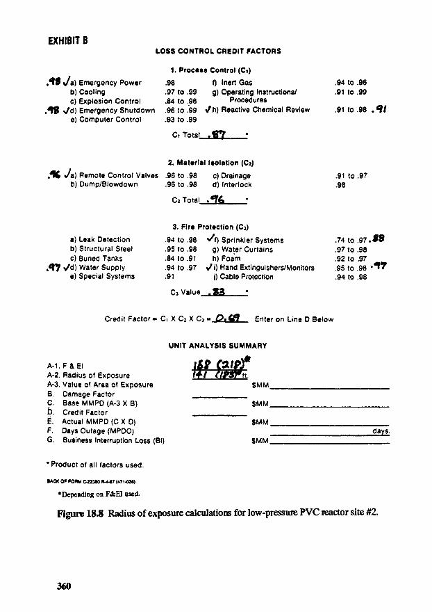
Figure 18Л Radius of exposure calculations for low-pressure PVC reactor site #2.
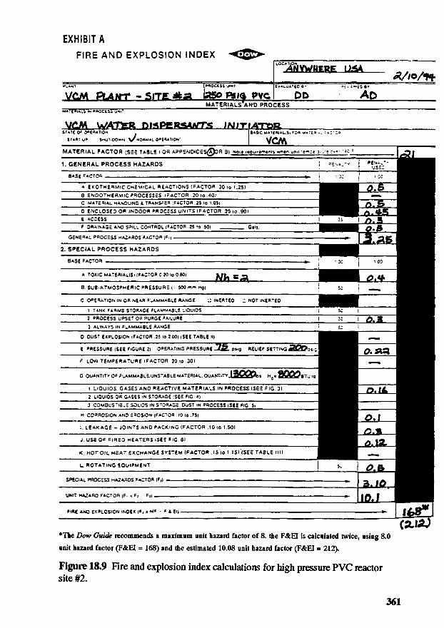
EXHIBIT A
FIRE AND EXPLOSION INDEX -4 >-r^MVWMEPE IMA
, , I ™Tmifc№ А/,о/Ъ" L A N t ' " process UNIT evALUAieo e» -a-.' i^Eoe»УСМ Bbftfrr - SITE ASi HSO REia PVC DP AD
MATERIALS'AND PROCESSMATERIALS IN PBOCcSS UNIT " " ~ " " " " " " " "
VCJA WATteR Pi^Pgg^WTS IMIT лтаи.S T A T C Q* OeE«ATiQN BASIC MATg^iAttSi ?0« w*:ia-. :»:"*
S T A A T . y P S«UT-OOWN V МОЙМА-. 0»£ЧАТЮ*' VC/WMATERIAL FACTOR (SEE TABLE i OR APPENQiCES^DR 3) N0<g r«Qu..«rncnis ~neo un.i ;«>*з«-а:.ч :•<•• •-•: '.- t I rp|1. GENERAL PROCESS HAZARDS i «MA.-V | P^A
S"-*V
BASE FACTO* fc- j : iC | 1 DCA gxQTH£R.V1lC CHEMICAL RaAC^iONS 1РАСТОЯ .30 to 1.25)
"" 8 ЕЦРОТн£Я.У11С?ЯОС£55£$ tr ACTOR .20 to .40) """С МАТ£Й1Аи HANDLING & TflANS^cS (PACTQff .25 Ю VOS)
"" D ENCLOScO OR »NDQQR PRQCsSS UNITS {FACTOR .25 »o .90) "~s ACCESS [ "f 0«A!NAG£ AND SPu.;. CONTfiCL [PACTQR .25 ю 50) Gals.
GcNERAL PROCESS HAZARDS FACTOR (?•)2. SPECIAL PROCESS HAZARDS
BASE FACTOR ».
A TOXIC MATERiAUS) (FACTOR 0.20 to 0.80) K/U wJStВ SUB-ATMOSPHERIC PRESSURE ( • - 500 mm HQJС OPERATION IN OR N£AR -ЦАММАЗиЕ RANGE ^ IN£RT£0 £ NOT iNERTEO
1 TANK FARMS STORAGE FLAMMABLE LIQUIDS2 PROCESS UPSET OR PURGE FAILURE3 ALWAYS IN FLAMMABLE RANGE
0. OUST EXPLOSION (FACTOR .25 to 2 00) (SEE TABLE »)E PRESSURE (SEE F.GURE 2) OPERATING PRESSURE 7^ pvg RELIEF SETTING 3G&3i^r LOW TEMPERATURE (FACTOR .20 to .30)
G QUANTITY OF FLAMMABLE-UNSTABLE MATERIAL: QUANTITY 13ООО*« н.. oQQQar i^i. LIQUIDS. GASES AND REACTIVE MATERIALS IN PROCESS (S£E PIG. 3)2 LIQUIDS OR GASES IN STORAGE :S££ P»G «l3 COMBUSTIBLE SOLOS IN STORAGE. DUST IN PROCESS (SEE PiG S)
м CORROSION AND EROSION (FACTOR Ю to 75)1. LEAKAGE - JOINTS AND PACKING (PACTOR .10 to 1.50»J. USE OF PIPED HEATERS (SEE FlG. 6)K. HOT OIL HEAT EXCHANGE SYSTEM (FACTOR .I5«o 1.15)'(SEE TABLE ill)
i - ..L ROTATING EQUIPMENT | 5w
SPECIAL PROCESS HAZARDS FACTOR (F,) , ».
UNIT HAZARD FACTOR (F. я F. F,) — — . ».
FIRE AND EXPLOSION INDEX (F, ж MF • F 4 El) i
*The Dow Guide recommends a maximum unit hazard factor of 8. the F&EI is calculated twice, using 8.0
unit hazard factor (F&EI = 168) and the estimated 10.08 unit hazard factor (F&EI = 212).
Figure 18.9 Fire and explosion index calculations for high pressure PVC reactorsite #2.
EXHIBIT ВLOSS CONTROL CREDIT FACTORS
1. Process Control (Ci)Я9 v'a) Emergency Power .98 f) Inert Gas .94 to .96
b) Cooling .97 to .99 g) Operating Instructions/ .91 to .99c) Explosion Control .84 to .98 Procedures
/в Vd) Emergency Shutdown .96 to .99 >/h) Reactive Chemical Review .91 to .98 . fe) Computer Control .93 to .99
Ci Total . Я7
2. Material Isolation (C2)Л4 <*a) Remote Control Valves .96 to .98 c) Drainage .91 to .97
b) Dump/Blowdown .96 to .98 d) Interlock .98
C2 Total .Tfe
3. Fire Protection (Сз)a) Leak Detection .94 to .98 </f) Sprinkler Systems .74 to .97 Mb) Structural Steel .95 to .98 g) Water Curtains .97 to .98c) Buried Tanks .84 to .91 h) Foam .92 to .97
. 7 vd) Water Supply .94 to .97 >Л) Hand Extinguishers/Monitors .95 to .98 Л^e) Special Systems .91 j) Cable Protection .94 to .98
C3 Value . 83
Credit Factor = Ci X C2 X Сз « О* 4Л Enter on Line D Below
UNIT ANALYSIS SUMMARY
A l F & E i us GLiafA-2. Radius of Exposure Hi ПЧйТпA-3. Value of Area of Exposure $MMB. Damage FactorC. Base MMPD (A-3 X B) $MMD. Credit FactorE. Actual MMPD (C X D) $MMF. Days Outage (MPDO) daysG. Business Interruption Loss (Bl) $MM
* Product of all factors used.
•ACK OF FOAM С-22ЭМ R-4-87 (471-036)
•Depending on F&EI used.
Figure 18.10 Radius of exposure calculations for low-pressure PVC reactor site #1.