HB SERIES TECHNICAL MANUAL Novatec, Inc 222 E. Thomas Ave. Baltimore, MD 21225 Telephone: 410-789-4811 Service Fax: 410-789-8923 Engineering Fax: 410-789-3051 Sales Fax: 410-789-4638 Parts Fax: 410-789-8923 Parts Email: [email protected]http:\\www.novatec.com Service Email: [email protected]
Revision Date Description A 08/27/98 Added Document P/N, DN. B 08/14/06 Added Dryer/HB interlock and high temp alarm info, MM.
HB SERIES MANUAL 3 DOCUMENT P/N10327 REV B
HB SERIES TECHNICAL MANUAL
TABLE OF CONTENTS
SECTION 1 ENGINEERING DATA SHEET SECTION 2 GENERAL DESCRIPTION SECTION 3 UNPACKING AND INSTALLATION SECTION 4 START UP PROCEDURES SECTION 5 MAINTENANCE SECTION 6 TROUBLESHOOTING GUIDE SECTION 7 PARTS LIST SECTION 8 TEMPERATURE CONTROLLER MANUAL SECTION 9 WARRANTY SECTION 10 FLOW DIAGRAM SECTION 11 WIRING SCHEMATIC & ASSEMBLY
DRAWINGS
HB SERIES MANUAL 4 DOCUMENT P/N10327 REV B
HB SERIES TECHNICAL MANUAL
SECTION 2
GENERAL DESCRIPTION
INTRODUCTION The HB Series is a continuous duty heater-blower package designed to supply uninterrupted flow of constant warm air. The unit is completely automatic and requires very little maintenance to offer many years of trouble free service. This unit features tubular (calrod) heater elements, solid state temperature control with thermocouple and a blower assembly. The HB package is used in conjunction with a hopper and may be used as a pass heater blower unit on non-hygroscopic material or it may used in conjunction with a NOVATEC CD/CDM series dryer to form a complete central drying system for drying hygroscopic material. PRINCIPLE OF OPERATION The blower assembly draws ambient air from the atmosphere or dry air from the CD/CDM series dryer and directs this airflow through the afterheater. The air is heated to a desired pre-set level in the afterheater and is then ducted to the drying hopper inlet. This warm air fills the hopper placing all of the entering material in a low humidity environment. The moisture on the plastic material is picked up by the air and is exhausted from the hopper to the atmosphere or through ducts back to the CD/CDM series dryer.
HB SERIES MANUAL 5 DOCUMENT P/N10327 REV B
HB SERIES TECHNICAL MANUAL
SECTION 3
UNPACKING AND INSTALLATION 3.1 Unpacking
Caution should be exercised to see that the equipment is not handled roughly. The HB is shipped completely assembled and requires no further attention prior to installation.
3.2 General Inspection
When the unit is unpacked, make a visual inspection looking for missing parts or damage that may have occurred during shipment. All electrical and mechanical connections should be checked for tightness, as vibration during transit may cause them to loosen. It is important that the electrical connections and buss box assembly on the heater be checked.
3.3 Installing the Drying Hopper
The inside of the hopper and perforated spreader cone should be thoroughly cleaned to remove all dust and oil that may have accumulated during shipment to your plant. 3.31 Machine Mounted
If the drying hopper is to be mounted directly to the process machine, it should be mounted in a vertical position. Secure the hopper with bolts through the bottom flange. Use braces or guide wires as necessary to assure a safe installation
3.32 Floor Mounted
If the hopper is to be floor mounted, locate the hopper stand in the space provided. Bolt the hopper stands to the floor. After the stand is in place, the hopper should be bolted to it in a vertical position and secured as required.
3.33 Platform Mounted
Bolt the hopper to the platform provided, and secure. Connect the dry material discharge to the processing machine inlet feed as required. This connection should be airtight.
HB SERIES MANUAL 6 DOCUMENT P/N10327 REV B
HB SERIES TECHNICAL MANUAL
3.34 Perforated Spreader Cone
After the hopper has been installed, the perforated spreader cone should be installed in the hopper. This cone rests on a flange near the bottom of the hopper. Be certain the cone is seated firmly to the flange.
3.4 Field Wiring The specific electrical wiring schematics supplied with the CD/CDM and HB/HBM equipment should be reviewed and completely understood before initiating installation. If there is any ambiguous or conflicting information, contact the Novatec Technical Service Department before attempting to install the equipment. 3.41 Dryer/HB Interlock Wiring Each HB has an interlock relay installed in its control box. The coil of this relay is connected in parallel to the dryer process motor starter coil. Should the dryer process blower shut off (ie; bed changeover, process blower motor overload), the HB interlock relay will power down the HB blower and heater. Typically the coil wires are labeled “A” and “B” on the terminal strip of the HB and dryer. Failure to interlock the HB relay with the dryer will not allow operation of the HB unit. Multiple HB’s can have the “A” and “B” wires daisy chained from one unit to the next. Usually the interlock voltage is 115Vac. 3.42 Utility Connection
Connect the proper power supply (see Engineering Data Sheet) through a main line disconnect (field supplied) to terminal block and ground in the control box. This is the only power supply required, as the unit is completely pre-wired and high voltage units are supplied with a control voltage transformer to supply 110 volts to the control circuit.
NOTE: In some cases the control box is remote mounted. In these instances, appropriate connections must also be made between the control box and the HB unit (see electrical schematic).
HB SERIES MANUAL 7 DOCUMENT P/N10327 REV B
HB SERIES TECHNICAL MANUAL
SECTION 4
START-UP PROCEDURE
4.1 With the electrical connection checked, and the proper power supply connected, see that the stop-start switch, located on the outside of the control cabinet, is in the stop position.
4.2 The dryer must be running before starting the HB units. Energize the unit by #1,
switching on the field supplied disconnect and #2, switching the stop-start switch to the start position.
4.3 On three phase units, first jog the stop-start switch to establish blower rotation.
(Do not assume that the blower is turning correctly if air is moving through the hopper. Blowers of this design move air in either direction). Make certain that the blower (s) are turning in the direction of the rotation arrow, by removing the filter (s) and observing the blower wheel, or by observing the fan end of the motor.
4.4 With the blower rotation established and the unit energized, check the electrical
leads in the control cabinet to see that the blower (s) are not pulling above the nameplate amperage (see nameplate on blower for amperage rating at proper voltage). If the unit is equipped with adjustable damper, adjust the damper so that the blower is pulling nameplate amperage.
4.5 Adjust the afterheater controller to the desired processing temperature. Adjust the
high deviation alarm setpoint to the desired value. Check each heater lead for the proper amperage. (See Engineering Data Sheet.)
4.6 If insufficient heat is available at the hopper the damper may be adjusted to
reduce the airflow and consequently increase the air temperature. Airflow on multiple unit installations, such as with a central drying system, may be balanced by adjusting the dampers. Motor amperage should be checked after adjusting dampers to make sure it does not exceed the nameplate rating.
HB SERIES MANUAL 8 DOCUMENT P/N10327 REV B
HB SERIES TECHNICAL MANUAL
SECTION 5
MAINTENANCE AND INSPECTION SCHEDULE
5.1 It is recommended that maintenance and inspection is one on a scheduled basis. Maintenance requirements will naturally vary widely for each installation and with specific operation conditions. It is suggested that a complete inspection with necessary maintenance at the end of the first month, the first three months, and the first six months. These inspections will be indicative of how often future maintenance will be necessary.
5.2 EVERY MONTH
A. Inspect air filters if supplied. Clean or replace as required. Replace if cartridge is broken. These time intervals for inspections should be shortend if experience indicates unusual dust loading.
B. Check system for air leaks and correct as required. 5.3 EVERY THREE MONTHS
A. Units equipped with sleeve bearing motors should be lubricated with SAE 20 oil.
B. Units equipped with ball bearings motors are factory greased and should be re-lubricated with high-grade ball bearing grease.
WHEN ADDING LUBRICANT 1. Remove filter plugs at the bearing and install grease fittings
suitable to your grease guns. Also, remove the drain plugs at the bearings.
2. Add ball bearing grease until all of the old grease is expelled through the drain hole.
3. Run motor with drain plug removed to eliminate excess grease. 4. Clean and replace drain plugs.
C. Check heater amperages (see Engineering Data Sheet) D. Check motor(s) amperage (see Engineering Data Sheet)
NOTE: Most units are equipped with sealed permanently lubricated bearings and no lubrication is required. All motors should be examined on an individual basis. If lubrication instructions are shown on motor, they will supercede these general instructions.
HB SERIES MANUAL 9 DOCUMENT P/N10327 REV B
HB SERIES TECHNICAL MANUAL
SECTION 6
TROUBLE SHOOTING GUIDE
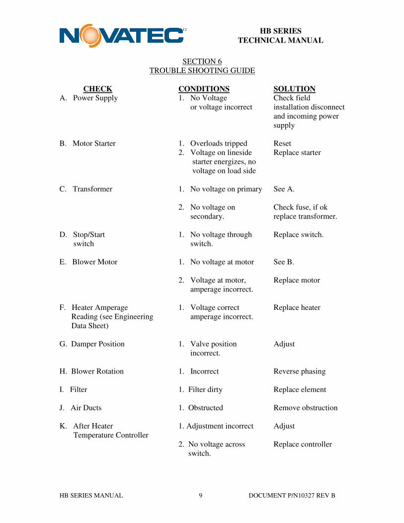
CHECK CONDITIONS SOLUTION A. Power Supply 1. No Voltage Check field or voltage incorrect installation disconnect and incoming power supply B. Motor Starter 1. Overloads tripped Reset 2. Voltage on lineside Replace starter starter energizes, no voltage on load side C. Transformer 1. No voltage on primary See A. 2. No voltage on Check fuse, if ok secondary. replace transformer. D. Stop/Start 1. No voltage through Replace switch. switch switch. E. Blower Motor 1. No voltage at motor See B. 2. Voltage at motor, Replace motor amperage incorrect. F. Heater Amperage 1. Voltage correct Replace heater Reading (see Engineering amperage incorrect. Data Sheet) G. Damper Position 1. Valve position Adjust
incorrect. H. Blower Rotation 1. Incorrect Reverse phasing I. Filter 1. Filter dirty Replace element J. Air Ducts 1. Obstructed Remove obstruction K. After Heater 1. Adjustment incorrect Adjust Temperature Controller
2. No voltage across Replace controller switch.
HB SERIES MANUAL 10 DOCUMENT P/N10327 REV B
HB SERIES TECHNICAL MANUAL
TROUBLE SHOOTING GUIDE
Most drying problems are the result of dirty filter (s), air leaks and malfunctioning regeneration heaters. It is seldom the other components fail. PROBLEM INVESTIGATE Machine won’t start A, B, C, and D Inadequate or no heat E, F, G, H, I, J, and K Inadequate or no airflow B, E, G, H, I, and J High deviation temp shutdown G, H, I, J, K Inadequate dew point Refer to troubleshooting