hb000 Handbook Index hb001 CVT introduction - the perfect sine wave ● hb003 CVT background ● hb006 CVT how does it work ● hb009 CVTgives lightning protection ● hb010 health and safety data - PCBs in CVT capacit ● hb011 health and safety data - PCBs ● hb017 CVTs with generators ● hb022 Earthing power conditioners ● hb025 CVTs outside specification ● hb026 AIT vs GT ● hb027 3rd world power protection ● hb028 sizing refrigerator conditioners ● hb029 health and safety data - CVTs ● hb036 CVTs with UPSs ● hb039 CVT start-up surges + fuses 400Vac ● hb048 maintenance of CVTs ● hb054 CVTs approval to international standards ● hb056 special casework for 3-15kVA CVT's ● hb057 CE conformance certificate ● hb058 selecting power conditioners ● hb059 weighing memorandum for special applications ● hb061 AIT series type-test results ● hb066 Safe Installation + 7671 - pt1 ● hb067 Safe Installation + 7671 - pt 2 ● hb068 Laboratory power facilities ● hb069 CVTs pairing and monitoring ● hb070 3ph open delta transformers ● hb071 digital camera problems ● hb072 ICT installation considerations ● hb101 retrofit wiring for EPoS ● hb511 MTBF of GT series with ambient ● hb514 COSHH data sheet UPS + PC ● hb563 Preventative maintenance checklist ● hb572 customer actions - top 10 ● hb594 method statement for install and commission ● hb607 method statement for fault-find + repair of ● Handbook Index http://advux/aelgroup.co.uk/hb/hb000.htm (1 of 2) [27/06/2003 12:08:56]
Transcript
hb000 Handbook Index
hb001 CVT introduction - the perfect sine wave●
hb003 CVT background●
hb006 CVT how does it work●
hb009 CVTgives lightning protection●
hb010 health and safety data - PCBs in CVT capacit●
hb011 health and safety data - PCBs●
hb017 CVTs with generators●
hb022 Earthing power conditioners●
hb025 CVTs outside specification●
hb026 AIT vs GT●
hb027 3rd world power protection●
hb028 sizing refrigerator conditioners●
hb029 health and safety data - CVTs●
hb036 CVTs with UPSs●
hb039 CVT start-up surges + fuses 400Vac●
hb048 maintenance of CVTs●
hb054 CVTs approval to international standards●
hb056 special casework for 3-15kVA CVT's●
hb057 CE conformance certificate●
hb058 selecting power conditioners●
hb059 weighing memorandum for special applications●
hb061 AIT series type-test results●
hb066 Safe Installation + 7671 - pt1●
hb067 Safe Installation + 7671 - pt 2●
hb068 Laboratory power facilities●
hb069 CVTs pairing and monitoring●
hb070 3ph open delta transformers●
hb071 digital camera problems●
hb072 ICT installation considerations●
hb101 retrofit wiring for EPoS●
hb511 MTBF of GT series with ambient●
hb514 COSHH data sheet UPS + PC●
hb563 Preventative maintenance checklist●
hb572 customer actions - top 10●
hb594 method statement for install and commission●
hb607 method statement for fault-find + repair of●
Handbook Index
http://advux/aelgroup.co.uk/hb/hb000.htm (1 of 2) [27/06/2003 12:08:56]
Outstanding Spike and electrical noise protection:
The very best power protection comes from a special type of transformer known as a Constant Voltage Transformer(CVT). Providing unparalleled reliability and conditioning performance, spikes and electrical noise are neutralised withattenuation as high as 75dB.
In addition the input and output transformer windings are physically separated. Known as Galvanic isolation thisseparation ensures that there is no direct connection between the mains supply and load.
A CVT therefore provides an impenetrable barrier to spikes and high frequency electrical noise. This barrier also works inreverse mode to prevent a 'noisy' load from polluting the mains supply itself.
Superior sag surge and brownout protection:
Mains voltage sags and surges are automatically corrected by a CVT.
When faced with an extreme surge voltage such as a local lightning strike the power conditioner will present a lowimpedance to the mains to protect both itself and any connected loads.
Automatic sine-wave generation:
using ferro resonant transformer technology means that each power conditioner will always generate a pure stablesine-wave even when fed from a polluted mains or square-wave supply.
A = INPUT
B = OUTPUTNO moving parts NO electronics ONLY magnetic magic
Perfect switched-mode-power-supply (SMPS) driver:
Ferro resonant transformer technology provides waveform shoulder-lifting - the CVT is the kindest way to drive aswitched mode power supply. Input surges are reduced prolonging life and conduction times are lengthened. In additionthe CVT provides harmonic buffering and improved reservoir capacitor hold up for the inevitable supply micro breakswhich occur with grid protection switching.
Oscilloscope hold-up picture ride-through picture
hb001 CVT introduction - the perfect sine wave
http://advux/aelgroup.co.uk/hb/hb001.htm (1 of 4) [27/06/2003 12:08:57]
Something for nothing: so long as at least 30% of the normal supply voltage is present the suitably selected CVT canprovide adequate power for your critical load.
Common mode noise attenuation Series mode noise attenuation
>
Regulation
Output within 5% for zero to full load Outstanding output regulation at low loads or high input voltages
Regulation outside of specification
hb001 CVT introduction - the perfect sine wave
http://advux/aelgroup.co.uk/hb/hb001.htm (2 of 4) [27/06/2003 12:08:57]
Output within 8% for zero to full load and nominal input +/-20%
Stabilisation
Output within 3% for nominal input +/-15% Even wider inputswings at below nominal loads
Power Factor
All units present a power factor to the supply which varies withoutput load.
The CVT will drive a wide range of power factor loads (+/-0.75)
Small changes in the output voltage will be found in comparisonto the setting with a resisitive load.
Output changes with frequency of input
hb001 CVT introduction - the perfect sine wave
http://advux/aelgroup.co.uk/hb/hb001.htm (3 of 4) [27/06/2003 12:08:57]
A 1% frequency change produces a 1.5% change in outputvoltage
Phase shift
There is a smal phase shift across the CVT varying with load
The effect was discovered during the 1930's in the USA by Joseph Sola a German born engineer.
The industrial use of ferroresonant transformers goes back to early 1940’s. Through the last 5 decades a series ofapplications has been found for products based on the technique. In each case the CVT has some feature which made it themost reliable and cost effective solution to the problem. These characteristics continue to make the CVT one of the mostcost effective ac power conditioners available.
Although different manufacturers use varying techniques the Advance CVT is normally based on a single transformerrather than an arrangement of transformer and separate filters. This lends itself to one of the most important aspects of theCVT its inherent reliability. Ignoring nuts bolts and other small components the unit consists of 3 or 4 windings and aspecial capacitor. With good manufacturing technique only the capacitor fails and a considerable time and effort goes intomaking this as unlikely as is practical.
The second major characteristics that the CVT is almost indestructible. It can be completely and continuously shortcircuited in use either at switch—on or from full load and the unit will be unaffected.
As can be seen from the output curve the CVT output characteristic is such that the published specification may be set atan arbitrary distance from the knee. This is important when comparing product from different sources.In situations whereit is correctly installed the CVT is unaffected by low input voltage but will present a low impedance to very high voltagesurges ensuring that in-line fusing or circuit breakers are opened before any damage occurs.
The graph of input current with voltage at fixed load shows this. It alsoindicates the normal operating ‘dip’ point. This means that the unit is selfprotecting to its supply and the critical load connected to it. The CVT providesthe most effective buffer available to near—direct lightning strikes on powerlines. The CVT also has the ability to provide usable output from low lineswhen operated below nominal power rating.
The third characteristic which makes the CVT suitable for more recent applications with computers is that there is limitedenergy storage in the resonating circuit. This means that the CVT is able to ‘fill-in’ small gaps in the power waveform (upto about 10 mS—half a cycle in a normal situation).
The output voltage waveform will not be a perfect sinewave but certainly one that will satisfactorilydrive modern computer based equipment. This waveform remains the same even if the input voltage isvery severely non-sinusoidal.
There is a limit to the dynamic range afforded by most designs but all CVT’s exhibit the ability to provide a stable outputvoltage curve from a varying source. Although usually specified over a + / - 15% range the CVT does not just ‘stop’outside this voltage range.
This is practically limited to a ± 25% input swing for a usable output unless very special design precautions are taken. Thisvoltage stabilisation is a continuous operation on a cycle to cycle basis. Power supplies in modern computers willaccommodate variations slightly larger than the planned ± 6% of most electricity supplies so it is usually straightforwardto get the power supply input inside the necessary band using a CVT.
Another major feature of the CVT is that it inherently absorbs high energy voltage spikes on the input. In addition it ispractical with careful constructional techniques to provide an effective barrier against lower energy ‘fast’ spikes which
hb003 CVT background
http://advux/aelgroup.co.uk/hb/hb003.htm (1 of 2) [27/06/2003 12:08:57]
cause data corruption in computers and computer-based equipment.
On the negative side the CVT is a large and heavy transformer with operating efficiencies around 90% at full load. It has asubstantial magnetic field and also produces a 50 or 60 Hz ‘hum’ dependent on unit size. The CVT is also frequencysensitive and will normally work at either 50 or 60 Hz.
We feel these features are more than offset by the knowledge that a properly selected and installed unit will usually curemains problems on sensitive equipment. There is still a limited number of applications for specially wound CVT’s withoutput waveforms which are essentially ‘square’ rather than sinusoidal for use in simple power supplies or heating/lightingarrangements.
AC stabilisation can be achieved using a simple magnetic device which has no moving parts.
This is a process of producing a constant ac voltage from a varying ac voltage supply and involves the use of saturablereactors. The latter may be incorporated in a special transformer magnetic saturation being produced in a part of themagnetic circuit.
The winding arrangement and construction of one such constant voltage transformer is shown in the diagram:
The core is a three-limbed shell with a magnetic leakage path dividing thewinding space. On the upper winding space is the primary and acompensating winding while the lower winding space carries thesecondary which has a capacitor connected across it. An increasingvoltage applied to the primary produces an increasing flux in the mainmagnetic circuit and the secondary voltage increases proportionally tothis voltage. The increasing flux produces an increase in the leakagereactance of the secondary and this approaches a value which resonateswith the capacitor connected across it. As the condition of resonance isreached the secondary current rises rapidly saturating the lower portionsof the magnetic circuit. The flux due to the primary is diverted throughthe magnetic shunt and further increases in primary voltage produceslittle change in the secondary emf. It increases very slowly and this isoffset by the emf induced in the compensating winding on the upperportion of the core which is connected in series opposition to thesecondary winding.
Thus once the secondary is brought to resonance the output voltage from the secondary and compensating windings isconstant and it is under these conditions that the transformer is used.
The advantage of this form of stabilisation is that it can be applied to the heater supplies in addition to any HT suppliesderived from it. Owing to the non-sinusoidal waveform however readings taken with the usual rectifier-type meters aresubject to error.
The compensating winding produces a small voltage which is used to 'buck' the output voltage.
To produce a sinusoidal waveform a further winding is added which is coupled via a magnetic gap. This extra'neutralising' winding can be arranged to provide a suitable amount of 3rd and 5th harmonics which when summed withthe output 'square' wave above results in a sinewave.
A first term equivalent circuit is also shown:
hb006 CVT how does it work
http://advux/aelgroup.co.uk/hb/hb006.htm (1 of 2) [27/06/2003 12:08:57]
When lightning strikes enormous amounts of energy are dissipated. If the strike is in any way direct or near direct thenmost substances hit will be locally vapourised. Electrical distribution systems have special isolating devices to restrict theeffects of lightning strikes on overhead wires. However overhead lines can pick up serious transients which will destroysensitive electronics if the `spike' gets all the way into the equipment.
Lightning
A typical lightning strike produces a waveshape which has a front edge of about 1.2µS and after 50µS the voltage willhave dropped to half its peak value. Special test equipment is available which generates a 8/20 µS waveform whichrepresents the lightning effect if the voltage is 6kV and the source impedance less than 2 ohms. A further popular test isbased on a 10/350 shape which is used in telecoms applications.
It is not generally appreciated that office and domestic electrical distribution wiring will normally `flash over' at about 6kVwhich limits the voltage expectation from local lightning strikes.
A typical `strike' may carry about 200 000 Amps which when applied to an earthed conductor will cause a huge rise in thelocal earth potential. This effect can cause quite large amounts of energy to be carried along local earth wiring. Particularattention needs to be given to this problem. See ICT wiring and considerations.
Bullet proof protection
Advance CVTs especially designed for computer protection provide one of the most effective barriers against lightningdamage. The CVT has a magnetic circuit which becomes a very low impedance when fed with high voltage.
If the unit is correctly installed with a protecting fuse or circuit breaker then the CVT will open the protection beforedamaging energy gets to the electronic equipment being protected.
This means that the computer or other equipment may be turned off inadvertently but it will be protected from theresulting distributed energy from the lightning strike. Such energy spikes are relatively common.
The only user action required is to replace the fuse or reset the circuit breaker and continue using the equipment.
If the strike is of sufficient energy to damage the incoming distribution wiring because of a direct strike then anything mayhappen.
hb010 Polychlorinated biphenyl (PCB) in CVT capacitors
We are still servicing old CVTs made as early as 1943. Some of our suppliers have historically used PCB in the electrolyteof high voltage capacitors. These capacitors were incorporated in the manufacture of constant voltage transformers for aperiod during the 1960’s and 70’s. Non-PCB capacitors were introduced in the period 1972-75. Advance/Gouldtransformer model numbers changed when the units ceased using PCBs in capacitors. Specifically:
CV prefix became ECV
CVN became ECVN
some CVN models later became TCVN and all of these are safe. The `E’ signifies `ecological’ and means that no furtherchecks are required.
1 CVT’s labelled Advance in our current red/antelope colours definitely use non-PCB capacitors.
2 CVT’s labelled Gould probably do not contain PCB in the capacitors.
3 CVT’s labelled Advance and coloured black grey or silver may contain PCB in the capacitors.
If a unit in use is reported by model and serial number to Advance Electronics we can advise on the likely capacitor type.
We offer to service any suspect CVT capacitors at cost and properly dispose of the offending component.
Please note that most newer capacitors are actually marked `No-PCBs’ or `Non-PCB’.
We have never used PCB in the actual transformer only in capacitor electrolyte.
Recent medical work suggests that PCB may be a carcinogen.
PCBs in capacitors used in CVT’s prior to 1972
A single capacitor may be disposed of as part of 1 cubic metre of bland rubbish having carefully wrapped the capacitor toavoid contamination during handling.
Significant quantities should be disposed of via :
POLYCHLORINATED BIPHENYLS (PCBs) were used as a liquid impregnant in power and lighting capacitors duringthe period 1950 - 1980 under such trade names as AROCLOR ASKAREL BICLOR CLOPHEN DUCONOLPYROCLOR.
It is now known that PCBs are NON-BIODEGRADABLE are stored by body tissue and build up in the FOOD CHAINgive off TOXIC FUMES when operated at HIGH TEMPERATURES and increase the risk of cancer in animals andhumans under these circumstances. There is strong evidence to show that PCBs attack welded metal seams and so producea leak without any external influence thus necessitating early removal action as no practical drainage techniques areavailable.
This major health hazard is now under review by an EEC committee and all knowledgeable Authorities are recommendingearly attention to the problems of identification and approved disposal of this substance.
HAZARDS
PCBs give off FUMES and VAPOURS above 55º C and most capacitors operate at this level. Strict precautions must betaken to prevent the INHALATION of these under conditions of container LEAKAGE and FIRE and any such exposuremust be reported to Health and Safety Officials concerned. Skin and eye CONTACT must be avoided at all costs andunder such circumstances copious IRRIGATION with EYEWASH or WATER becomes an immediate necessity followedby urgent MEDICAL ATTENTION. The irrigation fluid now becomes a hazard and must be CONTAINED. All TOOLSand CONTAINERS and MATERIALS which have been exposed to the FUME or LIQUID versions of PCBs must beSEGREGATED to avoid any CROSS CONTAMINATION. INHALATION INGESTION OPEN WOUND and SKINABRASION contact with PCBs is a medical EMERGENCY.
PRECAUTIONS
Avoid all DIRECT CONTACT with the body and ensure that an IMPERVIOUS barrier is protecting the skin beingparticularly wary of the presence of CUTS and ABRASIONS. Never use clothing made of an absorbent material at thecontact layer. All rubbers and most plastics are unsuitable for PCBs contact. POLYTHENE or similar material affords thebest protection when used as GLOVES OVERSHOES HATS OVERALLS ETC. GOGGLES should be of a CHEMICALgrade. The possibility of EXPOSURE to FUMES and VAPOURS necessitate the use of SELF CONTAINEDBREATHING APPARATUS. DO NOT SMOKE in the presence of PCBs. Do not dispose of neat or suspended PCBs inDrains Sewers Streams Effluent courses or any normal Waste Channels. Affix a prominent LABEL to all equipment whichcontains PCBs and initiate a formal COLLECTION and DISPOSAL PROGRAMME.
EMERGENCIES
CASUALTIES must be moved to FRESH AIR kept WARM at rest with OXYGEN if necessary and have contaminatedclothing removed if possible. Urgent evacuation to hospital under medical supervision is necessary. CONTAMINATEDCLOTHING must be removed as soon as possible to a suitable CONTAINER marked `PCB’. CONTAMINATED SKINmust be thoroughly cleaned with soap and water in a PCBs CONTAINER. INGESTION OF PCBs and any SKIN orCHEST or THROAT IRRITATION must be treated as a MEDICAL EMERGENCY. SPILLAGE must be absorbed withSAND ASH SAWDUST etc. and collected in a PCBs CONTAINER. All WETTED areas must be mopped usingabsorbent material soaked in PERCHLORETHYLENE or proprietary solvent such as GENKLENE and then collected inthe PCBs CONTAINER.
PROTECTIVE CLOTHING
Pocketless Terylene Boiler Suit with elasticated waist ankle and wrist grips. Chemical grade goggles. Heavy dutyPolythene Gauntlet gloves with thin Polythene disposable gloves inside the gauntlet and boiler suit sleeves. ProtectiveOvershoes fitted inside the boiler suit leg bottoms. Self-contained Breathing Apparatus. Impervious overall.
ACTIONS
hb011 health and safety data - PCBs
http://advux/aelgroup.co.uk/hb/hb011.htm (1 of 2) [27/06/2003 12:08:57]
Identify all Capacitors which are suspect of containing PCBs and obtain a COMPETENT VERIFICATION of theimpregnant used therein. LABEL as PCBs all Capacitors which are verified as such and institute a removal andreplacement programme of work following a competent understanding of the activity involved. All REMOVALACTIVITY must give priority to the prevention of leakage from an undamaged Capacitor and the minimising ofcontamination from a leaking CAPACITOR by way of fixing clamps and terminals. All PCB CAPACITOR UNITSshould be placed in a SEALED STEEL CONTAINER for subsequent transportation purposes. MOP UP all SPILLAGEand WETTED AREAS placing all agents and protective garments in the PCBs CONTAINER including washing solutions.Consider the need to replace cabinets and switchgear which may have been significantly contaminated with PCBs.
DO NOT SOLICIT INCOMPETENT JUDGEMENT on the suspect Capacitors.
DO NOT WAIT for the LEAKAGE to occur and make your Staff aware of the problems NOW.
Sophisticated computer systems sometimes use diesel engine driven generators for backup in case of mains failure.
Where our CVT’s are used for power conditioning in the normal mains mode it is desirable to take advantage of the CVTperformance when using the generator.
These notes provide some guidance on the potential problems which can be met together with solutions.
Neutral
Some generators do not refer the low side of the output to earth. This MUST be tied down to avoid damage to any of ourlarger catalogue units which have double primary shields.
Care must also be taken that the generator neutral is not connected to the CVT output low.
Frequency
All ferroresonant devices are frequency sensitive.
The generator must run close to 50 Hz for the unit to operate correctly.
Unfortunately the speed/output voltage curve for the generator goes the same way as the CVT so speed should be adjustedat actual running load.
We publish a curve for the effect of frequency variation in our CVT Handbook.
Short term off-frequency operation will not damage the CVT.
Phase
The output from the CVT will be out of phase with the input in cases where the generator supplies other equipmentdirectly some care is needed if a phase sensitive
triac firing circuit is installed.
Safety
Unless phasing circuits are fitted all circuits should use ‘break before make’ contactors and enforced supply separation.
Some thought needs to be given to the Regulations regarding out of phase supplies in the same area.
The earthing connections for conditioners installed to isolate noise are very important.
The unit is designed to isolate the load from the building earth as well as to provide voltage stabilisation and noiseattenuation.
The earth on the protected load may be connected to the safety earth but it must be realised that noise spikes on the safetyearth may cause problems.
This applies to so-called `clean’ or `dedicated’ earths run from the main building power distribution box.
Ideal installations have the input of the conditioner protected by the safety earth and a separate clean earth provided for thecritical load.
This can be achieved by an earth rod, water pipe (when suitably tested), or structure in tall buildings.
A `clean’ earth may be made by employing any of the following:
Earth rod
Most installations can be earthed by driving a 10 mm x 2.5 m long earth rod within 30 m of the critical load.
This rod is then connected using at least the same size wire as the feeder circuit.
Water pipe
A water pipe can be used if the resistance to earth is less than 6 Ohms.
Make certain by testing that the water pipe is not isolated by plastic connections, especially where it leaves the building.
Building structures
When the installation is in a multistorey building it will be necessary to connect to the structural steel for the clean earth.
Choose a point that is close to the conditioner and bolt a wire to the structure. Connections to the structure are usuallybetter than running a wire to the basement.
Earth usage
In those cases where the load is partially protected (some peripherals unprotected by the conditioner) we recommend thatthe low or pseudo neutral side of the conditioner output is connected to the clean earth to avoid voltages appearingbetween the floating output of the double wound CVT and the unprotected peripheral.
Further attention should be given to ensure that earth connections are `star-wired’ to the clean earth.
Local permanent wiring regulations should always be observed.
The four major options are as follows:
1 the output of the conditioner is floating with the safety earthwired through. Advance plug/socket units are like this. Unitfails normal earth loop impedance testing but is safe to BS3535. If one output is fault connected to earth the otherbecomes hazardous. The conditioner will work OK. If bothoutputs are earthed the unit will close down to a safecondition. Note that some poorly designed SMPS aresensitive to floating neutrals.
hb022 Earthing power conditioners
http://advux/aelgroup.co.uk/hb/hb022.htm (1 of 2) [27/06/2003 12:08:58]
2 hardwired using separate clean earth. This gives goodoverall noise performance. Clean earth must test out properlyand be isolated from safety earth. Clean earth should belabelled in UK to 514-7.
3 as 2 but establishment of quasi neutral. Output high is nowpotentially hazardous and should be connected via an RCCDif feeding sockets. Common mode noise may be better than 2above in some situations. For first time installations thisoption gives the most straightforward solution. Theconditioner operates like a new distribution transformer.
4 safety earth wired through quasi neutral. Common modeattenuation poorer. Installation should use RCCD withsockets.
The output is high-and-low not live-and-neutral so earthingthe low output terminal is entirely compatible with theRegulations.
All Advance catalogue CVTs are supplied and guaranteed to a
published specification. In general the CVT is specified to industry recognised norms and can be operated well outside itsdescribed performance specification. This note describes where liberties may be taken and should be read in conjunctionwith our GT generic specification which gives curves for many situations. This very robust product is particularly suitablefor the unpredictable electrical mains supply in third world countries. Our CVTs are still the most reliable and effectivemains protection for such applications.
High input voltage
if the CVT is operated with the correct input fuse or circuit breaker it should work OK until the protection opens at about150% of the nominal input voltage rating.
The output voltage will rise with increasing input at about 20% of the change - i.e. if the input goes up 5% the output willgo up about 1%.
Low input voltage
the output voltage will sag as the input voltage falls.
To operate under expected very low input voltage select a larger unit than normally required. Under loading the unit willprovide significantly improved results. Most units will provide usable power down to 30% of the rated input voltage.
Non-sinusoidal input voltage
If it is the correct frequency and alternating the CVT will operate.
A THD up to 25% or even a square wave is NO problem for short term durations.
Overloading
The CVT may deliver up to 50% more power than specified this is very dependant on actual input voltage.
After this the unit will self protect by reducing the output voltage progressively until it reaches nearly zero. The unit can beoperated into a short circuit indefinitely. Electric motors take large currents at switch on. If the CVT will start the motor itis big enough.
Power factor loads
Inductive loads depress output voltages and can usually be corrected by adding capacitors.
Capacitive loads have the opposite effect. If you can tell us about the load we can usually advise how to drive it.
Switching loads
Ordinary
switched mode power supplies are particularly suitable for use with our CVTs. Care must be taken with units with selfadjusting input voltage arrangements. Some dimmer circuits or phase controlled circuits can cause problems.
Wrong frequency
1 or 2 Hz off the correct frequency will produce low output volts for low frequency and vice versa.
50 Hz units will function at 52 Hz but will eventually fail if operated at 60 Hz.
hb025 CVTs outside specification
http://advux/aelgroup.co.uk/hb/hb025.htm (1 of 2) [27/06/2003 12:08:58]
Low temperature
Down to -25 ºC is usually no problem after that the capacitor bank becomes the limiting factor.
High temperature
For short term excursions of ambient temperature up to 70 ºC the only damage is to the life of the capacitor bank.
For every 5 ºC above 40 ºC expect the life to be halved from the calculated 200 000 hours MTBF.
High humidity
If the unit is stored at 100% RH it will probably require drying before starting up.
The unit will operate at 99% RH without problems.
Failed capacitor
If the unit has several capacitors and one fails the unit may still provide reduced power.
Shorted capacitors will stop operation but open circuit failures can be tolerated. Problems will occur at switch on if theunit is operated at high input voltage and light loads when a capacitor has failed. If the unit makes a ‘humping’ or‘motor-boating’ noise it should be turned off and on again. Failed capacitors should be replaced as soon as possible.
Damaged casework
We recommend that a thorough visual examination be made by a competent person prior to switch on.
Don’t connect a critical load without prior testing. Light bulbs and fan heaters make excellent test gear in remote locations.So long as all the wiring and insulation seems intact and the situation demands it we suggest you try it.
Other problems
Please ask for technical assistance via our sales office.
Those of us who are used to the high standard of electricity utility supplies in the industrialised world sometimes forget theproblems faced by users of high tech equipment in the third world. This page describes a strategy for planning electricalpower protection in a small business or professional office application. These notes may also be helpful to householdersfacing regular damage to electrical equipment - even just ordinary light bulbs.
The problems
These fall into different categories the critical load must be protected from one or more of the following:
out of tolerance voltages
(sags surges and brownouts)
spikes on the line
and/or keep working when
out of tolerance voltages occur
mains supply fails.
Most electrical equipment is able to function normally if the voltage varies by less than ±10%.
Modern equipment is also usually able to operate satisfactorily in an environment where small noise spikes (less than100V) arrive down the line.
However the data handled in modern digital equipment is sometimes corrupted by severe spikes.
Some of the equipment may be so critical that it needs protection from both noise spikes and power failure.
Other equipment may need protection from brownouts and/or very high voltages.
Planning a solution
A thorough survey of the various equipment loads around the business or office location should be prepared.
Each equipment needs to be classified. For example - critical essential non-essential.
The actual load of each item needs to be expressed in watts.
It is often misleading to take electrical ratings from external labels on the equipment to be protected.
Fuse ratings can also be much higher than actual consumption and should only be used as a guide where no measuringequipment is available.
Separate lists need to be made for the various loads showing which ones are critical and others which just need protection.
Consideration should be given to the possible need for a few lights to be supported when the mains fails so that criticalequipment (keyboards!) can actually be seen.
Attention needs to be paid to the problems of separating the various electrical wiring circuits.
It also makes sense to adopt some procedure for ensuring that the load is not used on the wrong supply.
Typical approaches include labelling or the use of different style plugs and sockets.
For some systems permanent wiring is sometimes an alternate solution.
hb027 3rd world power protection
http://advux/aelgroup.co.uk/hb/hb027.htm (1 of 2) [27/06/2003 12:08:58]
For more information or assistance in preparing a strategy please ask our sales office.
Typical strategy
Load Watts Protection equipmentlight bulbs TV video freezerhi-fi
2600 300 75 450 200 3625Advance power monitor disconnects the load whenvoltage goes outside predetermined limits
air conditioner 3000 tapping voltage stabiliser to maintain or APM as above
digital GSM phone 100Advance low impedance power conditioner preventsspikes getting to the phone memory
fax machine for incomingorders
150uninterruptible power supply brownout protection andbatteries when mains fails - specify backup time
personal computer with datawhich is essential
450UPS noise spike protection brown out protection + mustbe protected and batteries when mains fails - specifybackup time
laser printer modem scanner 1200 40 120Advance GT power conditioner noise spike protectionbrown out protection from mains supply these un-essentialitems go off when power fails
hb028 Sizing conditioners for refrigerator compressors
Background
Those of us who are used to the high standard of electricity utility supplies in the industrialised world sometimes forget theproblems faced by users of high tech equipment in the third world.
This page describes how the World Health Organisation addresses the problems associated with protecting the compressormotors on refrigerators.
The data is extracted from the WHO document entitled `Guideline for establishing or improving national regional anddistrict vaccine stores.'
Factors requiring consideration
The WHO presents data to assist in the selection of power protection equipment in section six of their recommendations:
"
6. Power Factors
6.1 Reliability
The reliability of the electricity supply is a key issue when choosing refrigeration equipment. Where power cuts exceed 8hours in 24 hours the use of ice-lined refrigerators and freezers is essential.
6.2 Standby generators
No refrigeration equipment currently available has a holdover time greater than 2.5 days. Vaccine will be destroyed ifthere is an extended mains power failure unless there is an alternative source of power. It is essential to assess the risk ofsuch failure. Failures may arise for many reasons. Examples include overloading of the power supply network;mechanical breakdown; lack of fuel or seasonal storms.
Replacing large quantities of damaged vaccine is expensive and extremely disruptive. It may not be possible to replacevaccines quickly because world stocks are limited. Emergency replacement from a finite world stock also disrupts thesupply of vaccine to other countries.
All sites stoning large quantities of vaccine should have a standby power supply. Often this is achieved most economicallyby locating the vaccine store in a hospital compound or on some other site which already has a standby generator. Whenthis is not possible it may be necessary to install a generator to serve the vaccine store alone.
6.2.1 Generator sizing and selection
The Product Information Sheets give advice on choosing and buying a generator and the EPI Equipment PerformanceSpecifications provide detailed specifications. Wherever possible the final sizing of generators should be made theresponsibility of the cold chain equipment supplier.
6.2.2 Generator control and operation
Generators serving vaccine stores only should be fitted with automatic starting devices linked into the cold room orrefrigerator/freezer alarm system. If the vaccine store is served by a compound generator this will generally be started byan automatic mains failure device. In such cases alarm-triggered start-up is not required.
All generators should be run at least once per week and should be regularly serviced to ensure that they remainoperational. The fuel tank should be kept full at all times.
hb028 sizing refrigerator conditioners
http://advux/aelgroup.co.uk/hb/hb028.htm (1 of 2) [27/06/2003 12:08:58]
6.2.3 Generator siting security and fire protection
A generator should be sited so that it does not create a fire hazard. Typically it should be located in a separate building orweatherproof enclosure. The fuel tank should be isolated and should be surrounded by a low wall or an earth bank toprevent fuel spills from spreading. Both the generator and the fuel tank should be located in a secure compound to preventtheft. The fuel filler cap tank should be locked and the fuel line should be protected so that it cannot be tampered with.Fire extinguishers capable of extinguishing fuel oil engine and electrical fires should be fitted dose to the generator andfuel tank.
6.2.4 Assuring fuel supplies
Fuel supply for the generator must be a priority allocation. A running log should be kept in order to monitor fuelconsumption.
6.3 Voltage stability
In many countries severe voltage fluctuations occur in the mains power supply. Voltage fluctuations greater than 15% willdamage compressor motors. The problem can be overcome by fitting each piece of refrigeration equipment with a voltagestabiliser. Some of the refrigerators and freezers in the Product Information Sheets are supplied with integral voltagestabilisers.
Voltage stabilisers for cold rooms should be specified by the cold room supplier. When a voltage stabiliser is ordered for arefrigerator or freezer the following information should be given to the supplier:
¤ Actual voltage fluctuations (recorded by an engineer or electrician)
¤ Nominal voltage
¤ Single or three phase supply
¤ Frequency (50 Hz or 60 Hz)
¤ Nominal power of compressor in watts
The nominal power of the stabiliser should be about five times greater than the nominal power of the compressor to allowfor the starting load."
We are grateful to the WHO for the opportunity to reproduce their recommendations.
These notes apply to all ferroresonant transformers made by Advance Electronics Ltd. at Wrexham.
Construction
The transformer consists of insulated copper wires wound onto an insulated former subsequently assembled onto steellaminations.
Advance power conditioners are double-wound transformers with tested secondary isolation from the mains. In additionhigh voltage capacitors are added into a resonant circuit configuration.
Installation
Advance provides detail installation instructions for all models and care should be taken to use them.
It is practical to meet the fundamental safety needs and yet retain a high level of earth integrity with a little care at theplanning and wiring stages.
Hazards
High voltage
The transformer must be correctly installed according to the requirements both of the latest edition of local wiringregulations and manufacturers recommendations.
Specifically proper in-line fusing or other suitable protection must be installed. Output voltages can be as high as 650 voltsand suitable RCCD protection and proper insulated fittings must be used in accordance with the needs of the application.The internal capacitors may run at 660 volts ac and are lethal when operating. The capacitors are safe when the unit isswitched off SO LONG AS THE ‘CAPACITOR TO WINDING’ CONNECTIONS are SOUND. Only authorised andtrained personnel should attempt repair.
Power
The unit is incapable of delivering more than 2 or 3 times its rated current in a failed mode and a maximum of less than75% of its rated output voltage.
Temperature
The steel stack of the unit may reach 60 ºC in normal air and precautions must be taken when repairing or testing exposedunits.
The exposed stack on small units does not reach an unsafe temperature but may feel quite warm to touch. All units shouldbe well ventilated as power ratings assume natural air cooling.
Chemicals
Once completed and all solvents have been burned off the transformer is chemically benign.
The capacitors contain paper insulation soaked in transformer oil which is relatively odourless and harmless to humanskin. Although messy this oil is only found if a capacitor leaks through some internal electrical fault in the capacitor. If thecapacitor is leaking the transformer is faulty and should be switched off. Historically PCB’s have been used in thecapacitors but Advance has not used any since about 1972.
hb029 health and safety data - CVTs
http://advux/aelgroup.co.uk/hb/hb029.htm (1 of 2) [27/06/2003 12:08:58]
Mass
All the transformers have a high density and suitable precautions should be taken in respect of the size underconsideration.
Noise
Audible noise at 50 Hz is emitted at different intensities depending on unit size. Levels range 45 - 65 dBA. If other higherfrequencies are present - checks should be made for potential faults.
Multi phase systems
Advance power systems can be wired in several different configurations.
In cases where more than one 240 volt phase is to be connected into one enclosure attention must be given to externalsafety labelling. The wiring regulations demand that 415 volt warning labels be affixed in visually prominent positionsafter installation. Suitable labels are enclosed if appropriate and replacements are available on request from Advance at nocharge to systems customers.
Self setting power supplies
During recent months an application problem has arisen with some types of UPS.
The problem specifically relates to customer loads which have self-adjusting voltage power supplies. This type of powersupply looks at the incoming mains and typically sets itself to either 115 or 230 Vac. If driven with any current limitingsource such as a CVT or CVT based UPS the power supply sets itself to 115 V and then is promptly supplied with 230 Vwhich usually means destruction of the customers' power supply.
Customers who have selected products with a load using this kind of SMPS should select a CVT which corresponds to thelower voltage input rating of the power supply or ensure that the CVT/UPS is switched on before the load. Most of theequipment we have seen with this type of 'world wide' power supply is small and rated below 1 kVA for razors andportable TV sets.
Modern on-line Uninterruptible Power Supplies (UPS) give excellent performance when applied as expected by thedesigner.
Sometimes superior noise immunity or voltage variation handling is required. This is usually accommodated by adding apower conditioning product to the UPS. Such installations are attempting to provide a much higher protection thanprovided by the simple RF filters in the UPS which are designed to stop internal noise leaving the UPS.
Potential pitfalls
The UPS was probably not designed with the expectation that it would be driven from something other than an ordinarymains supply. Some UPS have output circuitry which does not manage difficult loads very well. Once the user decides toadd the two products together it becomes apparent that there are several different ways to connect up the critical load.These different approaches give rise to various problems which can cause problems to the unwary.
Alternate scenarios
The UPS will normally have an automatic bypass if it is of the on-line type. We recommend that all such units should alsobe fitted with a maintenance bypass (either manual or automatic) for properly planned installations. The main problem isto assess whether or not the power conditioner should be put in front or behind the UPS. There also needs to be someconsideration about how the bypass operates and whether or not power conditioning is available in either bypass mode.
Considerations
It is not often realised that a UPS supplied in today's modern market place may have characteristics which are not properlydescribed in the sales literature.
For example the UPS output power rating is usually quoted with a `power factor’. The implication of this is that the unitmay be rated at 1000 VA but is quite incapable of supplying 1000 watts.
An on-line UPS has to support the full rated load whilst the system is recharging it’s batteries. This usually means that theunit requires considerably more input power than expected from the output rating.
The UPS may not have facilities to allow the bypass line to be connected to a different supply from the normal incomingmains.
The two major transformer based power conditioning technologies are `ferro-resonant’ or `low impedance’ types. Bothalso have internal inefficiencies and will require more power at the input when fully loaded than is available at the output.
The ferro-resonant types often based on constant voltage transformer (CVT) technology also have power factorconsiderations at both input and output.
The CVT is also less efficient than conventional transformers. However the CVT represents one of the most effectiveways to solve noise and voltage problems when applying UPS products in tough working environments.
Working solutions
UPS + low impedance conditioner (AIT)
In this case the conditioner may be used in front of the UPS to protect it against mains borne spikes and common modenoise. Clearly if it protects the UPS then it will protect the load against the same mains borne problems. The AIT must berated to provide enough power for the worst case input requirements of the UPS. These must be considered for anexhausted battery full load and worst case temperature conditions. In the absence of proper data use a rule that the AITshould have a rating which is at least 50% bigger than the UPS.
hb036 CVTs with UPSs
http://advux/aelgroup.co.uk/hb/hb036.htm (1 of 2) [27/06/2003 12:08:59]
It is also possible to use the AIT after the UPS to provide galvanic isolation and/or protect the critical load againstcommon mode noise generated by the UPS. The AIT will NOT provide any protection to the UPS input circuitry. Withthis connection attention must be given to the capacity of the UPS to drive the AIT. Typically the AIT wattage ratingshould be no larger than about 50% of the rated VA of the UPS.
UPS + CVT power conditioner
There are huge benefits to feeding a UPS from a CVT based power conditioner. These include lightning protection betterbattery recharge times and a benign mains feed for the UPS. The mains becomes essentially clean and complements thebattery back up features of the UPS. In this case however more problems are apparent.
The CVT is a resonant device which has unusual input characteristics. (See ds047) Consideration must given to the factthat the input power factor of the CVT is affected by line voltage and load value. Some UPS units will not drive inductiveloads at all. Others may struggle to cope with the varying power factor. Either way the UPS load rated at 1000VA with a0.6 PF rating on the output can only drive a CVT which is considerably smaller than one designed to deliver 1000 watts. Auseful rule is that the CVT should be considered to be 80% efficient and therefore the rating is:
UPS load rating VA * PF * 0.8
So a normal 1000VA UPS may only be adequate to drive a 480 watt CVT! For CVTs driving the input of the UPS theissue is entirely one of the worst case UPS needs. The rule above for the AIT can be used. Further attention should begiven to the fact that the CVT may provide a clean sinewave into a resistive load but it may not provide the low distortionwaveform required by some UPS chargers. This can cause the UPS to run it’s batteries flat.
Summary
The combination of a UPS and a power conditioner requires serious planning BEFORE buying equipment. If the two unitshave similar ratings they will probably not operate satisfactorily in any combination.
If one item is already installed it probably means that the only combination which will work is either a larger unit in frontor a smaller unit after the existing one. This usually means the second unit is too small to drive the critical load!
Our engineers would be delighted to assist with any problems relating to a specific installation.
The switch on current surge for a CVT consists of two components. One of these is fixed at about 8 times running currentfor 5 - 10 mSec. Superimposed on this will be a ‘spike’ which will be dependent on where in the mains cycle thetransformer was last turned off and where in the cycle it is turned back on. The spike will be less than 1 mSec and variesfrom zero to 25 times running current if the supply is very `stiff’. The input surge current at switch on is not significantlyaffected by the output load condition. The surge current will be substantially proportional to applied line voltage. Ournormal circuit breaker recommendation is to fit a ‘Type 4 ‘ or ‘Curve 66’ unit which should function without nuisancetripping. Fuse earth loop impedance and cable size suggestions are shown.
Fuse ratings
Fuses known as 'motor circuit fuse links' in BS 88 / IEC629 are ideal for CVT's. The GEC type 'T' H.R.C. are used in thetable and European types should be the type called `aM' or if available type `gTr'. We suggest that installers use awall-mounting switch fuse arrangement or 'red-spot' fittings. The table shows the MINIMUM fuse that can be used innormal installations, if using a breaker the choose the next size LARGER in your breaker range. Attention must be givento special cases where input voltage limits may go below the -20% figures used in the table. Cable sizes are also theminimum recommended by GEC for use with each fuse rating. The fuses will protect a PVC cable according to rule 433-2for 'open conditions'. Earth loop impedance is for SAFETY considerations and does not reflect the needs of a clean earth.Protection against electric shock is provided by these fuses when correctly installed. Part numbers are based on GECpublished data and some so-called direct equivalents may not be suitable. Discrimination must be proven under therequirements of the current edition of the local permanent wiring regulations BS 76711992 - it remains the responsibilityof the installer to ensure that the supply is protected.
Output fuses
All Advance CVT’s have automatic overload characteristics. In normal situations the output current will limit at about 2times rated current. The output voltage will collapse to near zero dependent on the fault impedance. It is impractical toprovide a fuse that will remain intact for normal full load use and definitely open under fault conditions since the CVTdoes not and cannot supply enough energy. We therefore recommend no output fusing be used except where other highpower conductors could become connected under fault conditions to the output circuit of the CVT or the fuse required ismuch smaller than the output capacity of the unit. If it is essential to protect the output we have had good success withthermal circuit breakers.
Since the CVT is capable of developing a steady current when marginally overloaded and exhibiting an output voltagewhich is slightly lower than normal it is practical to protect the load wiring with a thermal breaker. The breaker should bechosen so that under all normal operating conditions it will not see it's rating. If a fault occurs causing excess current toflow then the breaker will eventually open - even if the overload is only 105-110% of the breaker rating. The breaker willopen quite quickly in the event of a short circuit in the secondary load wiring.
hb039 CVT start-up surges + fuses 400Vac
http://advux/aelgroup.co.uk/hb/hb039.htm (2 of 3) [27/06/2003 12:08:59]
Routine checks should be made to ensure that the ventilation for the power conditioner is properly maintained.
The unit should be positioned in a well ventilated location as power ratings assume natural air cooling. Annual checks ofcapacitor integrity may be worthwhile once the unit is more than five years old.
Preventative maintenance
Visual examination of capacitors on large units can often indicate a local fault through
leakage of oil - in this case replace the faulty part. To prolong usable life it can be beneficial to replace the capacitor bankevery five years. Some larger power conditioners are fitted with fans to assist with cooling. Under normal circumstancesthe only preventative maintenance required is the cleaning of fans if fitted.
Replacement of capacitors
We are occasionally asked to supply replacement capacitors for old CVT's.
Capacitors are subject to two characteristics which affect the use of these spare components in CVT's.
a value tolerance
b physical dimensions
a - changes in capacitance value will result in differences in the CVT output voltage.
In general terms we expect normal production tolerances in the value of a spare capacitor to make less than a 1% change tothe original output voltage nominal setting. This situation can be improved when a coloured dot is noted on the failedcapacitor and it's colour dot is defined at the time of ordering a spare. The output voltage variation expected with CVT'susing a spare capacitor of the same colour dot will be less than 0.3%.
b - the physical dimensions of commercial capacitors change over extended periods of time. In general terms ourcapacitors will be of similar size or smaller. In case of any anticipated problem we recommend a factory repair for units upto 3 kVA. Care must be taken when handling high voltage capacitor installations. Replaced capacitors must have anadequate Vac rating for duty with high harmonic currents.
There is currently no international specification which relates directly to constant voltage transformers.
A draft specification exists for UPS products (BS EN50091-93) but this is unlikely to be more applicable to CVTs thancurrent specifications.
Existing approvals
The CIT range up to 1500VA has been approved to NEMKO NEK-EN 60742 and SEMKO 115X.
The Smartstab conditioners rated 100-1000VA have been designed to meet SEMKO 115X.
Potential approvals
UL
Some of the GT series were approved by UL but we have allowed this to lapse through lack of sales to interested parties.
We also used to have an insulation system approval but this has been allowed to lapse for the same reason.
We have no technical problems with meeting relevant UL specifications but the commercial cost of upkeep is uneconomic.
Customers who must have approval for their equipment may request that we design for the standard required.
When the equipment comes up for overall approval we provide constructional data to facilitate the approval process of ourcomponent.
Our customer remains responsible for the commercial upkeep of the approval as required.
CSA
Generally as per UL.
CE
We expect to comply with all the European Directives as and when applicable.
By getting certification to EN 60950 or EN 60742 we hope to have product safety acceptable for the USA and Canada aswell as EEC member countries.
Current status on CE marking is covered on handbook sheet HB 53.
A generic Certificate of Conformance for CE requirements is available as HB 57.
EMC
We are in the process of having sample catalogue units third-party tested and plan to use the self certification method formost OEM items.
Our product is particularly suitable for filtering out mains conducted noise on old equipment.
Safety
We are in the process of having sample catalogue units third-party tested and plan to use the self certification method formost OEM items.
hb054 CVTs approval to international standards
http://advux/aelgroup.co.uk/hb/hb054.htm (1 of 2) [27/06/2003 12:08:59]
There are a number of transformer related specifications. There are also relevant specifications in the office equipment andinformation technology areas.
Where necessary we can review any one of our units to a particular specification.
We have supplied a number of different designs to meet various specifications as components and are happy to do thiswhere customers need it.
Component Approvals
We maintain a computer file of international specifications held by various components which we use.
This is integrated with our Bill of Materials software and can be used to print a list of approved items in any of ourproducts.
A file of master copies of component approval certificates is maintained.
Feedback
We would be pleased to review this document with any interested party.
Advance uses a range of special casework for CVT’s from 3 to 15kVA.
Details of the various options are given to assist designers to specify particular requirements. The basic CVT based powerconditioner is similar in each unit but variations are available for
optional output fusing
cable access
terminal arrangements
optional fan cooling
The table indicates overall sizes of special enclosure with all sides removable.
Baseplate fixing holes are the same as the catalogue unit described in ds051. The special cover is fitted so that it’s centre isover the centre of the baseplate fixings.
standard arrangement
same side terminal style
hb056 special casework for 3-15kVA CVT's
http://advux/aelgroup.co.uk/hb/hb056.htm (1 of 4) [27/06/2003 12:08:59]
top entry terminal style
hb056 special casework for 3-15kVA CVT's
http://advux/aelgroup.co.uk/hb/hb056.htm (2 of 4) [27/06/2003 12:08:59]
optional fuse holder location
alternate fuse holder position
hb056 special casework for 3-15kVA CVT's
http://advux/aelgroup.co.uk/hb/hb056.htm (3 of 4) [27/06/2003 12:08:59]
dims in mm Height with
VA Length Widthbottom entry
internalgland plates
top entryexternal
gland plates
3000 40005000 60007000 8000
100001250015000
725 505
575 575 680680 680 950
950 11501150
680 680 950950 950 1150
1150 13201320
shows alternate gland plate styles for same side and oppositeside cable entry
It is not essential to take on-site measurements but this process can be useful when the status of a site is unknown.Sometimes it is more economic to just experiment with a known good filter such as a CVT.
We offer a loan scheme to potential and existing customers.
Advance can also provide ac mains monitors for checking of local mains supplies. Our monitors check the incomingsupply against various voltage and noise thresholds which are adjustable by the user. Some other environment data canalso be recorded such as the temperature. Results are normally printed out but can be RS232 linked via a modem to aremote site.
Interpretation of readings
Over the years we have had some problems with various monitors providing misleading results. Care must be taken toevaluate the results obtained against reasonable expectation for the site. Common pitfalls include using the same monitorto measure the input and output of a filtering device. This results in the noise spikes bypassing the filter through themonitor! Sometimes there is a very poorly defined line between cause and effect.
On particularly bad sites we have eventually connected a conditioner to a simple resistive load on the secondary of ourconditioner and monitored the voltage across the load. This removes the chance of extraneous noise data coming from anunknown load situation Such practice can also alleviate the problems of mains difficulties being mixed with unrelated datacorruptions and failures due to other causes.
Specifying the conditioner
The application must be reviewed for some basic parameters before we can quote for the supply of a suitable unit. Inaddition background information can be very helpful in choosing the right technological solution.
The technical information suggested on hb055 is a good starting point.
hb059 Special applications - UK weighing memorandum
Background
The National Weights and Measures Laboratory (NWML) is a section within the Department of Trade + Industry.
NWML has instructed officers in the field to ensure that remote weighing sites are properly protected from an electricalsupply point of view.
In cases where remote weighbridges and similar equipment is operated from small generator supplies there is a mandatoryrequirement to fit power protection devices in series with the electrical supply.
Memorandum WM 429
The NWML has issued a Memorandum describing both the equipment which must be protected and how. The main part ofof the Memorandum is transcribed here: An original is available on request from your local Weights + Measures.
DTI logo
NATIONAL WEIGHTS AND MEASURES LABORATORY WM 429
Department of Trade and Industry (November 1988)
Stanton Avenue Teddington Middlesex TW11 0JZ
Memorandum for the guidance of Inspectors of Weights and Measures
WEIGHTS AND MEASURES ACT 1985
Section 12
The Secretary of State has issued the following amendments to the respective Notices of Examination/Certificates ofApproval.
Generator powered equipment amendment No. 1 dated 14 October 1988
Type of Machine Code Index
Counter machines V (2) d V (2) e
Platform machines V (6) d
Weighbridges V(6) d
Person weighing machines V (6) f
Overhead weighing machines V (7)
Milk weighing machines V (8)
Suspended weighing machines V (9) a
Crane weighing machines V (9) b
Issued by NWML
Digital electronic machines and associated approved peripheral equipment.
As described in the Notice or minor modification to the Notice of Certificate or authorised variant thereof but having
hb059 weighing memorandum for special applications
http://advux/aelgroup.co.uk/hb/hb059.htm (1 of 2) [27/06/2003 12:09:00]
where appropriate the supply from a local generator in place of the mains supply.
In which case there shall be between the generator and the weighing equipment a constant voltage transformer AdvanceGT series of between 100 VA and 1000 VA rating. The rating chosen must be such that the minimum load on the CVT isnot less than 5% of the rated output of the CVT and the maximum load including transient loads such as printing does notexceed the rating of the CVT.
The output of the CVT must be dedicated to the weighing systems and either:-
(i) hard wired directly to the system or
(ii) via a non standard connector in which case the output shall be marked "for weighing system only".
The Advance series of AIT power conditioners was introduced some years ago to provide a highly effective noise filter formodern ICT equipment. The technical differences between the AIT and our traditional ferroresonant power conditionersare covered in hb026. However we are routinely asked for type test results relating to their performance. Perhaps the besttest is the high integrity of all the thousands of installations world-wide in telecomm and EPoS applications.
Features
The technical results show that the electrical performance of this type of conditioner is second to none for noise spikeattenuation. Common mode noise is virtually eliminated and transverse mode noise is reduced well below any CBEAMAthreshold. In addition the unit provides galvanic isolation between the input and output. These conditioners haveconservatively rated magnetics to accommodate the large surges and high crest factor loads found in modern SMPS. TheAIT is ideally suited to office applications where small size and low audible noise are of paramount importance.
Benefits
Protected ICT systems will not be damaged by the high energy spikes associated with lightning striking overheaddistribution wires. Other electrical mains-borne noise will either be reduced to an acceptable level or completelyeliminated. The AIT reduces warranty and power supply maintenance costs of ICT equipment to a minimum.
Results
The results shown are typical for a range of type tests designed to stress the unit as far as possible without destroying it.
Electrical safety
AITs comply with Class 1 to EN 60950 BS 1362:1973 BS 1363:1984 sect 12 + 13 BS 2754:1977 Units were tested withBS standard finger and pin and found compliant.
Breaking capacity
Fuses comply with BS 1362.
Flammability
Materials found to be compliant with UL 94VO.
Insulation resistance
Between any two terminals the insulation resistance was >2MOhms measured at 500Vac. (Mains neon and protectionelements removed).
Voltage regulation
A step change from 10 to 90% in applied load was made in less than 1mS. The output voltage decreased by less than 5%.
Critical phase angle
The AIT is insensitive to the effects of phase angle.
Load side surge protection
hb061 AIT series type-test results
http://advux/aelgroup.co.uk/hb/hb061.htm (1 of 2) [27/06/2003 12:09:00]
An impulse generator capable of producing a combination waveshape of 2.4kV open circuit and 200A short circuit wasused for this test. No electrical or mechanical damage occurred.
Electrical fast transient
The surge generator used is capable of producing a 5nS/50nS waveshape of 2kV open circuit voltage and a 2.5kHzrepetition frequency. The test waveform is applied for 15mS every 300mS for 10 minutes. The waveform is described inIEC 801-4 1988. For both polarities the peak voltage appearing on the output terminals was <400V.
0.5çS 100kHz ring wave test
Positive and negative polarity tests were made LN/LE/NE. Output voltages were <10V symmetric and <0.5V asymmetric.
Impulse discharge limiting voltage
A generator capable of a current of 5kA peak 8 x 20uS waveshape into a short circuit was used to apply 30 testsincorporating both polarities and all terminals. Output voltage peaks were all < 800V.
Failure modes
The 5kA 8 x 20uS waveshape blew the input fuse as required on all tested samples.
Overcurrent performance
The units were tested with slowly increased loads until the overload protection operated. Units must run for >2 hours at aload just below the point at which protection operates. Case temperatures remained below 46¤C
Mode transfer
The 5kA 8 x 20uS waveshape was applied between LE and measured between LN + NE. The 5kA 8 x 20uS waveshapewas applied between NE and measured between LN + LE. At no time did the peak impulse output voltage exceed 200V.
Insertion loss
The symmetric and asymmetric insertion losses were measured using both methods described in BS 6299 section 4.1Appendix A. Insertion loss was <65db over the range 10kHZ to 30MHz. Negligible noise is transferred between modes.Waveforms relating to these tests can be viewed at the factory.
Installers of permanent electrical wiring are required to ensure that new work meets current regulations. The UK wiringregulations have been converted to a BS specification (BS7671) which at the time of writing is being CENELECharmonised. Current regulations are designed to ensure that new installations are safe under fault conditions. `Safe’ meansthat the installation cannot harm a user OR cause a fire. For normal industrial and domestic site work the required testingusually covers BOTH needs.
In some special cases where the wiring is modified by local conditions EXTRA tests and results must be considered beforea site can be signed off by the installer. There may also be situations where commonly used test equipment may damagepart of the installation and defeat one or more reasons for the test. As manufacturers of electrical power conditioningequipment we offer the following guidelines to the extra special conditions which must considered.
Power Conditioning Equipment
This may be an in-line filter or a generator. The filter may be of a galvanically isolated type. The generator may be a smallrotary type or the static inverter found in uninterruptible power supplies (UPS).
The wiring regulations and good practice are founded on the expectation that electrical power is derived from a lowimpedance source. Fault conditions usually result in the clearance of a protective element such as a fuse or magneticallyoperated breaker. Most power conditioning equipment is by it’s very intention NOT low impedance.
In addition there may be electronic or magnetic control of either voltage or current which cause the equipment to have areal impedance which is modified in operation to an apparent impedance. The installer must be aware of the criticalschematic for the equipment being installed and consider all operational modes of current path selection devices. Inaddition distribution discrimination must be shown in the usual way.
Special considerations
Two different views must be taken in cases where the supply is provided by an apparent or actual higher impedancesource:
The first consideration is user safety:
the installer must ensure that when any live conductor is connected by a fault to an exposed earth that the resultantVOLTAGE is not unsafe. (In practice it is assumed that the fault is zero impedance) The voltage generated across the earthimpedance (Ze) by the fault current must be `safe’. Although this is usually below 50 volts good practice and marginsmean that a target of 5 volts is more realistic. If there is significant source impedance (Zs) whether real or apparent thismust be considered in the calculation of the worst case fault current.
The second consideration is fire:
the installer must consider the worst case CURRENT under any one fault condition. If the apparent source impedance ofthe supply (shown as Z) is large enough to prevent the wiring from overheating then the protection is NOT required toopen.
hb066 Safe Installation + 7671 - pt1
http://advux/aelgroup.co.uk/hb/hb066.htm (1 of 2) [27/06/2003 12:09:00]
Since there is an almost infinite variety of potential installation variations even using our own products some furthersuggestions for ensuring safe installation are outlined in hb067.
A typical uninterruptible power supply (UPS) requires EXTRA calculations to be performed before installation andsign-off.
In the illustrated case the UPS has no galvanic isolation and the earth + neutral go through the unit. The recommendedbypass switch means that it is possible for the distribution wiring to see the low impedance mains supply.
For the first part of the calculations the UPS should be ignored and the wiring calculated out in the normal way. It isunlikely that when the UPS is introduced into the system that the rating of any wiring will have to be increased EXCEPTthe input supply.
Input supply
Most UPS equipment is not 100% efficient. In addition to supplying the full rated load current modified by the UPSefficiency there is a need to support the battery charger as well. The UPS manufacturer should provide worst case inputpower needs. For longer supply runs this often means that a larger wire is required than expected for an installation wherethere is no UPS.
Testing
For the first part of the testing the UPS should be isolated and the distribution connected to the main supply via the bypassswitch. Normal checks should be applied using calibrated equipment.
NOTE: some modern pulse-based testing equipment can damage electronic equipment which should normally bedisconnected during testing.
The second consideration is where the distributed power is supplied by the static inverter in the UPS. This has real andapparent impedance. The apparent impedance is electronically controlled and should be specified by the UPS supplier as aworst case current available from the UPS.
For user safety the installer must ensure that the earth loop impedance is sufficiently low so that it provides a voltageinside regulations for the worst case fault current available from the UPS. It should be appreciated that under theseconditions over current fault protection may not clear.
For fire safety the installer needs to evaluate that all the distribution wiring will not overheat or it must clear protectionunder fault conditions. If the current is below the continuous current rating of the wiring the apparent source impedancemay mean that the protection does not clear.
There are inevitable compromises with ALL methods of Electrical Power Conditioning. It is up to the USER to establishwhich technology provides the most attractive solution.
Flexible power solutions for Laboratory Installations
In the Test House or Specialised Test Facility where a variety of solutions can be required it may seem that the mostflexible solution is to provide a number of small stabilisers and battery back-up units which can be moved around to thepoint of application. Experience shows that there is one extra major advantage to planning the needs when the facility isunder construction and wiring out several power supply options to every general purpose test station. The advantage is thatALL power conditioning products have ratings which are determined by cost and if the distributed conditioning iscombined into a central facility it is less likely that a test piece will be too large for a mobile conditioning solution.
Two Constant Voltage Transformers are fed from two separate supplies the outputs of the CVT’s are both connected to thesame load. Under normal conditions each unit supplies approximately 50% of the load power. If one of the supplies failsthe back-feeding transformer is made safe and the remaining transformer provides all the load power without anydisruption. Either CVT may be isolated and safely removed while the system is operating and the CVT maintained orrepaired. Replacement is best done at service shutdowns but can be done on-line if essential.
DUAL INPUT CONTROLLER
Two separate supplies are connected to the input terminals. Each supply passes through the main poles of a n/o contactor -the coil of which is controlled and monitored by current sensing relay and associated circuitry.
The supplies then exit the controller via output terminals to be connected to the inputs of two Constant VoltageTransformers.
The supplies in the controller are indicated by neons. The supply to each transformer is operated by locking the key switchin its "closed position 1" and pressing the green "on" button. When the supply has failed the both neons are off. If the red"off" button is pressed then only the "CVT - input on " neon is off.
PAIRING AND MONITORING SYSTEM
The two separate outputs from CVT ‘A’ and CVT ‘B’ are connected to the input terminals. (Terminals S1 S2 S3 and S4 inboth systems must also be interwired to provide a supply to the main contactor coils).
The main wiring then passes through the main poles of the N/O contactor (the coil of which is operated by the currentsensing circuitry in the dual input controller) and then paired together at the high - low output terminals (to which thecritical load is connected).
The load sharing of each transformer is monitored on the two ammeters with the output voltage of the system is shown onthe voltmeter.
Provision is made for remote alarm circuitry by using N/C contacts on the alarm terminals
The `open delta' transformer is still the best way to transform the three phase output of a UPS into a single phase. Ingeneral it is better to try and avoid the transformer all together. However there are some considerations about the loadcharacteristics on the UPS. The phase currents supplied by the UPS will be unbalanced. This unbalance is calculated thus:
assume the load is resistive assume the transformer ratio is 1:1 assume the supply is 400Vac and the load required is1kVAthe load in the input centre limb must equate to the sum of the other two inputs the voltage across the load must be400 square root 3 = 692.8V for 1kVA then 1000/692.8 = 1.44A therefore current in common leg is 2.88A for each kVA of1PF load
In specific applications care must be taken to assume that
the transformer is only 94% efficient the voltage may not be 400 ph-ph the UPS may have difficulty with the unbalancedload the PF of the load may affect the calculation
A sample calculation is shown:
for a 20kW single phase load a 20kW transformer is required the transformer will require 20*2.88A * 230Vac=13248watts on the common transformer leg the UPS will need to provide 3 times this if it has three separate inverters and 2times this if unbalanced loads are tolerated the power is 13248*3=39744 watts - assuming the UPS has a capacity toprovide only a 0.8PF the UPS size is 49600VA! the transformer is about 94% efficient meaning a final figure of52.851kVA is appropriate
A much better solution is to use two units rated at 12kW and run them in parallel
If the application cannot supply a single phase at the required load a cost effective solution is to use a single phase inputUPS with a phase/phase input transformer rated 400/230Vac on the input to the UPS.
The advent of very high quality scanning backs for studio cameras has caused a new interest in mains related image noiseproblems. Most photographers are not engineers and this page attempts to provide enough information for a studio camerauser to try and evaluate whether or not a particular problem may be solved with mains power protection devices.
Diagnosis before cure
In most technical applications where problems occur it is usually easier to effect a cure if the problem is actuallyunderstood. By examining images which have been produced by a suspect digital camera under differerent conditions itmay be possible to eliminate possible causes of a problem. It is also necessary to have to hand the expected performancefor the camera. If the camera was never intended to produce an acceptable image under the conditions of test - then noamount of mains protection is going to improve it! (Some camera manufacturers have been reluctant to give measurablefigures for performance and we feel this is unacceptable.)
Popular image problems
We usually ask photographers to examine poor images for the following problems:
variation in lighting conditions during the scan
An example of this is in a studio where ambient daylight is illuminating the subject and the sun goes in or out during thescan. In the simplest example where the sun starts behind a cloud and comes out during the scan there will be an overallbrightness increase across the image in the direction of the scan. The change will be directly related to the rate of changeof sunlight variation compared to the rate of scan. Clearly elimination is straightforward.
variation in artificial lighting due to mains problems
SPIKES
- these short duration occurrences can produce bright spots in one line of pixels caused by the light actually brightening upmomentarily - unusual even in direct off mains tungsten lighting because the spike energy has to be quite large. This effectis normally completely random.
BROWNOUTS
- this is where the mains voltage sags and the light given out by unstabilised tungsten lights literally dims down for thesame period as the voltage droops. The result is similar to the sun going behind a cloud during the scan. (This process canwork the other way with voltage surges) and may vary considerably during a scan.
variation in artificial lighting due to mains frequency beats
The UK mains supply is modulated at 50 Hz (cycles per second) and direct-off-mains tungsten lights (ordinary bulbs)flicker at this frequency ALL THE TIME! The human eye `integrates’ the effect and does not notice it.
This causes a problem which is always difficult for non-physicists to understand but musical people are familiar with toneswhich `beat’ and the same effect can happen when the effective scan rate is close to 50Hz or a multiple. The result is thatsome lines of pixels see bright light and some dark.
The picture will have a series of `fringes' parallel to the scanning sensor - width and spacing of the fringes will be set-upand scan-rate dependent. Cameras have anti-fringing software to combat this problem. Usually the result looks like avenetian blind shadow over the image. It can also produce multicoloured effects not just light and dark beacuse only onecolour channel may be beating.
hb071 digital camera problems
http://advux/aelgroup.co.uk/hb/hb071.htm (1 of 2) [27/06/2003 12:09:01]
light path obstruction
If a piece of dirt is stuck to the scanning sensor it will produce a (usually coloured) line in the direction of the scan.Usually the line is across the entire frame and the problem can only be corrected by using cleaner techniques. If the sensoris clean and the line is always the same colour it suggests that the sensor is faulty.
camera technology
this is a huge subject and only briefly touched here the image faulty areas should be pushed to the limits of installedsoftware using mainly contrast and brightness adjustments to view the image pixel by pixel to try and assess what isactually happening as the sensor moves along.
If there is quite a lot of colour variation along the line of pixels when scanning an evenly illuminated area it is probablydirectly related to any interpolation in the process or sensor/amplifier inconsistencies. (Users should appreciate that theanalogue scanning data is converted to digital information right after the scanner head. The A to D process is where theelectronics value really costs!)
Colour variation in the image under these conditions must be reviewed with the supplier specification to assess if it istypical or worse than usual for the camera back. Tests should be done at different scan rates and exposure combinations(f-stop & light change) to try and discern the relavance of the fault to external influences.
`Fringes’ which occur along a distinct line of pixels across the scanning sensor are consistent with a change in camerasystem amplifier gain between successive pixel rows and really should not happen.
If a step function in the overall `gain' characteristic occurs on a random basis check the fringe to see if it gives theimpression that the back slowly drifts in it’s gain value and then suddenly regains control going back to a figure fromseveral pixel lines previously in the scan. If so it can be either mechanical sticking of the traverse lack of amplifier gaincontrol or a voltage fluctuation caused by changing loads elsewhere.
Summary
Sometimes it helps to build a test setup to eliminate external influences and still demonstrate that the back producesproblems. A simple battery driven lamp which has no 50Hz and no spikes! It can be arranged to have no droop through theactual scan process by using a relatively large battery. The best approach would be a car battery and a couple of headlampbulbs. To be utterly pedantic the bulb voltage could be monitored during the scan.
The subject should be a nice plain background with a small object used temporarily to set up the correct focus to simulatean actual shooting scenario. This test would eliminate a large proportion of the external influences which could otherwisebe erroneously blamed.
Finally if after evaluation it is felt that the camera is really suffering from a direct or indirect mains related problem pleaseask us for help.
We can provide a UPS to provide power when the mains is down a power conditioner to remove spikes or a moresophisticated one which stabilises the voltage suppliying either the camera lights or both. Normally we would loan a unitto allow the photographer a chance to prove what may be an expensive cure actually solves the problem. We have at leastone obsessive photographer on site!
Installers of permanent electrical wiring are required to ensure that new work meets current regulations. These regulationsare designed to save life in the case of faulty wiring or equipment. Further the practice is regulated to make our officesfactories and homes safe places to live from a fire risk point of view.
ICT systems
Unfortunately modern equipment suffers from a wide range of other influences. Some of these may actually causesensitive electronic chips to fail. Just wiring up and performing routine regulation oriented checks is inadequate whenmission critical or crucial systems are involved.
Considerations
By the time the wiring is being installed it is already too late. The retro-fitting of a star earthing system after a computerroom has just been quite safely wired up involves a full strip out and re-install.
Safety
The regulations require that all permanent wiring is compliant with safe practice. Normally this means calculating fusesizes and selecting wire sizes to create protection discrimination and quick disconnect.
The electrician is required to bond all exposed conducting elements in an equipotential zone together. As a practical matterthis is normally done in a daisy chain fashion which is entirely safe. From a noise diversion point of view it can be adisaster. Just checking earth loop impedances does not mean that no earth loops exist in the protective wiring. A properstar plan must be evolved and the installer should prove the installation before connecting sensitive equipment. Theregulations are covered by BS 7671 (until recently `the 16th edition').
Noise
Transients can occur naturally in our environment (lightning) and in heavy equipment switching. Specific attention mustbe given to the likelihood for such occurrences and a planned approach used to divert them as quickly as possible to earth.
Earth cabling should not be connected to more than one star point and all cables should radiate like spokes in a wheel.
Data cables between equipment must be checked for earth isolation at one end of the screen.
Data cables going outside the equipotential zone may require specific fitting of surge diversion boxes. This also applies tophone lines. Recommendations are given in BS 6651.
Static electricity
The static charge commonly experienced as a definite spark between humans and earthed objects in dry weather willdestroy the silicon chips in a computer or telephone switch.
Aliens
ICT equipment mains circuitry should never be available (preferably by the use of hardwiring or special plug tops) to alienloads such as the office kettle or vacuum cleaner.
Networking
As our systems become more complex and critical to our daily business operations all installations should be planned forbest practice. Networked systems are particularly prone to problems appearing in unexpected places. Modem lines
hb072 ICT installation considerations
http://advux/aelgroup.co.uk/hb/hb072.htm (1 of 3) [27/06/2003 12:09:01]
monitoring communications and transducer signals with long wires connected to the network are perfect aerials to collectharmful spikes.
to avoid earth loops
Introduction
With the ever increasing use of Information + Computer Technology (ICT) equipment there is a greater chance ofinstallation with unsatisfactory wiring.
History
The traditional UK electrician is taught to earth all metallic chassis. His training is directed towards making allinstallations safe. If single phase work is properly carried out he will check that the three conductors are definitelyconnected where they should be and definitely not where they should not be! Clearly he will also check for correct use oflive and neutral and prove discrimination on fusing. He may also install added safety protection in the form of an RCCD.
Today
These checks are no longer adequate. We have found that some wiring which is perfectly safe is quite unsuitable for ICTequipment. In some cases the use of mains noise protection equipment could be avoided by better wiring practice.However it is usually less expensive to retrofit protection rather than re-wire a whole building or even just the computernetwork. A better solution is to approach the problem at the planning stage. In addition to ensuring that the wiring is safesome specific attention must be made as early as the planning stage for wiring practice which ensures the best results fordata processing equipment. After the installation is complete some extra checks should be carried out while the system isnot connected to the supply and conductors may be temporarily disconnected.
Practice
The objective is to provide a totally safe installation without any earth `loops’. An earth loop can give rise to surprisinglylarge currents in low impedance circuits.
These currents can cause mysterious data processing faults hum problems and failed communication ports on PCBs inEPoS equipment.
Good results
The diagrams show the incidence of an earth loop and approaches to wiring to avoid them. In simple terms all equipmentmust be earthed in only one place.The following checks should be done on the wiring of a system prior to considering if itis satisfactory for ICT use.
1 ALL existing statutory checks should be made.
2 The `star point’ earth connections should be opened and all related equipment checked for isolation from earth.
3 On installations where there is galvanic isolation provided by a mains noise protecting device the galvanic isolation mustbe proved.
Checks should be made for both earth and neutral conductors.
4 Once inter peripheral data or video lines are connected the earths of EACH peripheral need to be checked for singleconnection only.
(This is best done on a networked system by removing all mains plugs from their sockets and seeing if any plug earth pinis connected to any other)
hb072 ICT installation considerations
http://advux/aelgroup.co.uk/hb/hb072.htm (2 of 3) [27/06/2003 12:09:01]
Incidence of earth loop via data cable screen and peripheralearthed chassis
Preferred practice for wiring two conditioning products to thesame star earth
A number of customers have asked us to document an approach to the replacement of poor EPoS wiring in recreationalestablishments
The need to re-wire is usually to ensure that the EPoS systemis correctly connected and that no unrelated loads are on thesame circuit
Where a site is prone to noise related problems caused byunknown or unpreventable causes the re-wiring will notnecessarily make all the historical problems disappear.However it does mean that the wiring arrangement is clearlydefined and will not have any earth loops
In addition the provision of both a dedicated line clean earthand the absence of all earth loops often solves transient noiserelated problems. In all cases the current regulations must beobserved. The diagram shows the principles of the new wiringarrangement
The Spur
The EPoS equipment is generally fed from a single spur protected by an MCB
This spur should be routed around the building avoiding runs close to other wires - especially high power cables. The wire(conventional twin and earth) must be sized according to current regulations
The MCB
Type 4 is desirable to allow for the high switch on surges of CVT types of Power Conditioner
The Earth
The earth is derived from a dedicated earth rod of suitable impedance. NO other equipment should be attached to thisearth.
Care must be taken to ensure no earth loops exist. This can be tested by disconnecting the earth rod from the spur andchecking all gear is isolated from earth
The Power Conditioner (PC)
This will usually be one of two types.
1) CVT based unit with voltage stabilisation and `bullet proof' noise protection. The CVT also provides soft start to theload and waveform re-build and well an enhanced ride-through for mains micro breaks
2) AIT series low impedance conditioner designed to remove ALL common mode noise
In either case the clean earth is fed to the unit as a safety earth. If a CVT is fitted the output `low' MUST also be connectedto the earth. For the AIT series this connection is internal
General
It is good practice to ensure that no free sockets are available for non EPosS loads - kettles vacuums etc.
hb101 retrofit wiring for EPoS
http://advux/aelgroup.co.uk/hb/hb101.htm (1 of 2) [27/06/2003 12:09:01]
If for any reason RCCDs are to be fitted they will only protect the load if installed AFTER the PC
The installer should check the wiring is NOT connected to any other circuit
The system data cabling MUST be checked to ensure that the earth screens are only connected at ONE end
A diagram of the completed installation MUST be kept to assist further investigation if problems persist
Advance's GT series power conditioners have an ambient temperature rating of 40C.
The family can be used in higher ambients without derating but MTBF is reduced.
Units up to 2900VA need not be derated. For large units please consult the sales office.
Ambient Air ºC MTBF hrs
40 200 000
45 100 000
50 50 000
55 25 000
60 12 500
65 6 250
MTBF calculated to MIL 217C ground benign.
In addition Advance can design tailor made versions for a specified Temperature.
CVT Failure Modes
The CVT is basically a saturated transformer with an output resonant circuit maintained by a capacitor.
All transformers have the failure mode of "shorted turn" where winding damage causes a part of the winding to short(either to earth or to another layer ). This leads to large current flow in a small part of the winding typically blowing aninput fuse or breaker.
In addition windings can go open circuit leading to either no output from an energised transformer or no energisation.
This can happen only on the INPUT of a CVT, because the OUTPUT winding is current limited, in the case of a shortedturn on the CVT output, it is unlikely the current draw will be sufficient to blow an input fuse before the CVT output"folds" to zero volts. In fact it is possible to directly short the entire output winding of a CVT and then remove the shortwithout damage to the CVT and restoring the output as soon as the short is removed.
In addition to standard transformer failure modes the CVT capacitor can be considered a weak point. Advance uses onlyGE Capacitors that are specially designed for the rigorous duty required in a CVT. These capacitors are oil filled and some"ageing" of this oil occurs causing a recommended replacement after 8 years, based on a 10 year expected life span. Thecapacitor has an integral fuse, which can cause an open circuit on failure, since this leads to a loss of saturation in theoutput the symptoms of capacitor failure are low output voltage.
Some CVT's are fitted with protective earth screens on windings to improve attenuation of high frequency noise. Thesescreens can short to each other but the only effect is to reduce the attenuation at high frequencies.
hb511 MTBF of GT series with ambient
http://advux/aelgroup.co.uk/hb/hb511.htm (1 of 2) [27/06/2003 12:09:01]
hb514 COSHH datasheet for Advance UPS + Power Conditioners
Scope
This sheet refers to all catalogue UPS and Power Conditioner products supplied by Advance.
Policy statement
The company does not use any of the following substances in the manufacture of its products:
Asbestos (blue/brown or white) Benzene or related carcinogens Cadmium for plating components Halogenated(Chlorinated/Fluorinated) solvents Ozone depleting substances Polychlorinated Biphenyls
UPS + Power Condtioners
Although we are required to control some of the substances produced during the manufacture of these products all arecovered by the guidelines provided by COSHH consultant ORL dated Oct 1989.
No substances described in COSHH regulations are present in significant volumes in finished product EXCEPT for thosefound in electrical storage batteries in UPS products.
These items are manufactured to be leak free and can only be a chemical hazard if damaged.
Attention is drawn to our Health + Safety data sheets safe battery handling and safe battery disposal.
Occasionally we are asked by companies who are unfamiliar with the application of UPS products to help with planning anew installation
This list of headings is a 'top ten' of considerations for a new installation:
1 Consider the whole picture
there is no point in making the computer or telephone switch operate when the lights are out the main ISDN is down orsome local network hub just went off with the mains power
2 Select the right topology UPS
there is a wide range of prices for any size of UPS ensure that you select the right variation for the application
3 Fit a bypass
all electronic boxes fail at some time all batteries need replacing eventually. The correct bypass switch (auto or manual)protects the system the UPS and gives a genuine choice of power when all goes wrong! Maintenance can also be carriedout during working hours.
4 Install + commission the system properly
use a qualified contractor - meet the current regulations - prove protection discrimination - get right size cables fitted use acompetent agent to demonstrate the unit functions properly and get the site signed off for safety + integrity
5 Plan maintenance
establish a routine for battery discharge testing in REAL load situations to ensure an adequate capacity is available newbatteries will be fitted in time and NOT before necessary if necessary clean fans
6 Buy a maintenance contract
control cost of ownership and ensure a fast response in times of need using a standard plan
7 Fit a status panel
there are low cost status monitoring boxes to enable you to keep an eye on the health of the UPS
8 Use the software
if the mains fails at 7pm and the battery autonomy is only 4 hours the system should shut down the load long before thebattery is useless so that some options are available when power is needed the next day for business. UNIX and similaroperating platforms REQUIRE orderly shutdown to avoid cost downtime during the rebuilding of a File System
9 Hook up to a national monitoring service
if you need real protection get the supplier to monitor the UPS from his heavily protected national resource the serviceengineer may be knocking on your door before you know you have a problem!
10 Read the manual
at least TWO members of staff should be familiar with the usually simple external UPS controls and/or the bypass
hb572 customer actions - top 10
http://advux/aelgroup.co.uk/hb/hb572.htm (1 of 2) [27/06/2003 12:09:02]
This assessment is predicated on the user providing risk free attendance for the Advance customer service engineer (A-GCSE) at the UPS to be serviced or repaired
The user is also deemed responsible for ensuring that the A-G CSE is fully aware of local hazards
The A-G CSE is required to adhere to all local site health + safety regulations
Location Detail
work to be carried out at premises
actual UPS location
site contact
start date
expected duration
Description
model no of UPS
serial no of UPS
reported problem
maintenance bypass fitted
Hazard
risk before repair low
risk of electrocution by ac electricity supply if no bypass switch - load to be disconnected
all ac equipment to be isolated or supervised whilstexposed
remote incomers must be labelled and locked off
risk of electrocution by dc electricity supply safe battery handling techniques will be applied
reduce risk by disconnect input supply prior to service/repair
Risk assessment for installation + commission of a UPS
This assessment is predicated on the user providing risk free attendance for the Advance customer service engineer (A-GCSE) at the UPS to be serviced or repaired
The user is also deemed responsible for ensuring that the A-G CSE is fully aware of local hazards
The A-G CSE is required to adhere to all local site health + safety regulations
Location Detail
work to be carried out at premises
actual UPS location
site contact
start date
expected duration
Description
model no of UPS
serial no of UPS
maintenance bypass model no
Hazard
risk before install low
risk of electrocution whilst using electrical test /measuring equipment
electrical test probes must be suitably fused
risk of electrocution by ac electricity supply
reduce risk byremote incomers must be labelled and lockedof
all ac equipment to be isolated or supervisedwhilst exposed
Installation of a maintenance bypass removes the need to power down the load during routine maintenance or capacityupgrade of an Uninterruptible Power System (UPS). The bypass switch has two positions
Mains power UPS power
Manual operation of the switch directs whichsource of power feeds the load. A maintenancebypass is normally wall mounted adjacent to theUPS.
Maintenance bypass switch types There are two types of maintenance bypass switch: Make-Before-Break (MBB)Break-Before-Make (BBM) It is normal to install a MBB switch in an installation which requires a 'break-free' powersupply as the BBM typically suffers from a 5ms break when turned between switch positions.
Internal or external bypasses Some UPS boast that they incorporate an internal maintenance bypass switch. This hastwo drawbacks
If the UPS needs to be removed the load will still need to be powered down.●
As the UPS cannot be totally switched off (dangerous ac and dc voltages may be present whilst the engineerperforms routine maintenance)
●
'Plug and Play' or hardwired There are two types of bypass installation. An installation may be either hardwired orsoftwired (more commonly known as 'Plug And Play').
'Plug And Play' This uses standard IEC sockets and may be used with any UPS installation up to a maximum of 2kVA.Above this rating the hardwired approach is adopted due to the higher amperages involved. The 'Plug And Play' bypasshelps to improve logistics co-ordination and reduce the higher installation costs associated with larger UPS and the moretraditional hardwired approach. Its use of standard 'plug-in' connections removes the need to have an electrically qualifiedengineer attend site. An additional benefit is that UPS utilising the 'Plug And Play' approach are normally usercommissionable.
Hardwired The standard IEC sockets used on a 'Plug And Play' bypass and UPS have a maximum supply current 10A.Their use is restricted to UPS up to 2k5VA for 240Vac installations and 1kVA for 110Vac installations. In such instancesthe bypass must be hardwired. A typical installation powers the UPS from a fused spur. The output from the UPS ishardwired through the bypass to the load.
For more details see FBS series and special needs version or bypass considerations
Most Advance customers choose to allow the company to deliver their order to site. Where a customer wishes a collectioncan be made from our UK factory. In either scenario the company recommends that consideration is given to thefollowing:
UPS weight and size
UPS weight increases with capacity and battery support time. If the UPS is of a large VA rating and/or has a large batterysupport time the floor loading of the system should be assessed. For some larger systems it may be necessary to install aspreader plate. On raised platforms such as in computer room installations the platform may also need extra supportsinstalling.
Delivery route
Advance sub contracts its delivery service to one of two specially chosen (and ISO9001 monitored) carriers. The chosencarrier may use a normal wagon or one with a tail lift. In either scenario the customer should ensure that adequateoff-loading facilities exist such as a fork lift and that the UPS can physically follow the delivery route to its final restingposition. Where access is not direct and over level ground stair climbing and/or lifting gear may be required. If a lift isused its loading should be check. Customers should ensure that they work to the gross packed dimensions and weights.
Access for maintenance
Where a UPS is installed into a non-custom designed room the UPS may be sited into the most available space. Usersshould ensure that access to the UPS is available for service and maintenance work. This can vary between UPS designand ratings.
Extended battery support times are normally supplied in matching battery cabinets. For some large installations batteryracks may be used where the battery terminals may be exposed. In such instances it is recommended that the battery andUPS are installed in a lockable room.
Delivery day and time
Standard deliveries take place inside normal working hours normal working days. Special rates apply for deliveries outsidenormal times.
Standard kerbside delivery
The company uses the UK carrier network to provide a delivery to kerbside service. The service has a maximum weightlimit per item of 140kg.
The delivery company is contracted to deliver the consignment to the nearest vehicle access point to the final location.
The delivery driver does not carry any specialist lifting or siting equipment. For larger consignments customers areexpected to provide suitable lifting gear to take the equipment from the delivery vehicle. The carrier is not contracted tounpack the equipment or dispose of the packing materials. There are two delivery services: am next day and 2-3 dayservice.
Specialist delivery siting and positioning service
The company uses a specialist carrier to provide a full delivery service including siting and positioning.
The carrier is contracted to provide delivery over level ground with easy access to the agreed location on the customer'spremises. The carrier may be asked to unpack the equipment and dispose of the packing materials. The delivery servicehas a delivery date and time arranged to suit the customer and the delivery route. The service can also provide a two mandelivery with specialist equipment such as stair climbers by prior arrangement. Crane hire and removal of existing UPS
hb704 delivery and siting
http://advux/aelgroup.co.uk/hb/hb704.htm (1 of 2) [27/06/2003 12:09:03]
At the heart of most computer and telecommunications hardware is a Switch Mode Power Supply (SMPS).
The SMPS converts the ac (alternating current) mains supply into the levels of dc (direct current) required by the logiccircuits.
It is designed to operate on a normal mains supply. Some may have the ability to cope with a limited range of mainsfluctuations. Designed to a minimum cost base in a highly competitive market they are the first pressure point in anInformation and Communications Technology (ICT) application. A fluctuating mains supply causes ‘wear and tear’ on theSMPS’ components. This leads to operating conditions where it cannot perform crashes or eventually fails.
The second is the internal processing hardware. This requires ‘tight’ levels of dc to operate effectively and uses internalmemories to store data prior to saving to some type of storage device e.g. a hard disk floppy disk tape back up optical diskor flash ROM.
When mains problems cause the SMPS to operate erratically or fail information processing and operation are affected.Information may be lost the system may hang files can be corrupted and the hardware malfunction or even be damaged.
The ICT user is faced with hardware replacement file recreation and downtime costs. The hardware supplier incurscharges to write off against maintenance income.
Common mains power problems
When mains is present the most common types of power problems are spikes electrical noise sags and surges.
Spikes and electrical noise are associated with the use of modern office equipment heavy industrial machinery and nearbylightning strikes.
Sags and surges can be less common unless there is a significant decrease in the capacity of the utility companies toprovide electrical power or the site is in a rural location.
Mains failures can be less damaging than spikes electrical noise sags and surges. However they can cause the maximuminstantaneous disruption.
Power protection
The natural reaction to mains power problems is to install some form of Uninterruptible Power System (UPS) protection.This may not be the most suitable approach.
Advance tackles power problems by considering whether the application must be kept running at all times how long itshould run for and the degree of mains pollution present.
Does the load have to be kept running at all times?
In such instances a UPS must be installed. It should have a sufficiently wide input voltage window to cope with sags andsurges in the mains supply.
How long must it run for?
The standard UPS runtime is typically 10 minutes. The UPS types shown below are those from the Advance range whichcan have extended runtime packs (and chargers) fitted.
How polluted is the mains supply?
For sites where the mains supply is heavily polluted by spikes and electrical noise the UPS may need some form ofGalvanic Isolation transformer.
hb707 UPS vs power conditioning
http://advux/aelgroup.co.uk/hb/hb707.htm (1 of 2) [27/06/2003 12:09:03]
This forms a physical barrier between the input to the UPS and its load. It is the most effective protection against spikesand electrical noise. It can be built-into the UPS at the design stage or installed as a second component in the UPSinstallation.
Types of UPS
UPS vary in performance and price.
This is due to the technology used to provide an ac power source from the battery i.e. with a break or without and theinclusion or not of a Galvanic Isolation transformer.
1. ByteBak®The UPS provides a clean stable electrical supply over a wide voltage window. It is a no-break system withsome protection from spikes and electrical noise. If Galvanic Isolation is required an AIT series power conditioner (seebelow) can be installed after the UPS.
2. Elite®The UPS is an on-line system with automatic system bypass in case of an overload or alarm condition. It providessome protection from spikes and electrical noise and operates over a wide input voltage window. If Galvanic Isolation isrequired an AIT series power conditioner (see below) can be installed after the UPS.
3. MicroBak®The UPS is based on a similar transformer to the GT series power conditioner (see below). It provides thebenefits of Galvanic Isolation over a wide input voltage window and a no-break battery supply.
Can the load can stand a break in the mains supply?
Where the application is unaffected by a mains failure (or the budget is not available for a UPS) a power conditionerbecomes the preferred solution. Advance power conditioners are transformer based and provide Galvanic Isolation. Anymains borne spikes and electrical noise are routed directly to earth. The protected load receives clean computer-gradepower.
Types of power conditioner
1. AIT series power conditioners provide protection from spikes and electrical noise. They are a ‘fit and forget’ low-costand maintenance free product recommended for applications such as EPoS and small PBX applications.
2. GT series power conditioners provide the benefits of an AIT series power conditioner coupled with the ability toprovide voltage stabilisation over a wide input voltage window. They are recommended for all SMPS and otherapplications which cannot cope with a widely fluctuating mains supply.
Other relevant topics
The bulletins listed below may also be relevant to this topic.
An Uninterruptible Power System (UPS) typically has a standard runtime of 10 minutes.
This can normally be extended through the addition of extra battery extension packs for critical computer andtelecommunications applications.
Battery extension packs
Introduction
Most of our UPS product is supplied with an internal battery pack to permit a minimum `run-time' performance.(Occasionally a unit may be supplied without batteries when customers have their own dc supply)
Run times + Battery sizing
It should be appreciated that batteries come in a range of fixed sizes and UPS products usually only work from one dcvoltage
This means that if the required performance cannot be achieved with a certain battery configuration the next size up mustbe selected. Sometimes it is worthwhile reviewing the expected run-time using the smaller battery since it will provide amore economical solution and may only miss the target by a few minutes
Performance with actual running load
All our published run times are based on using the UPS at full load and with fresh batteries. A significant extra run-timewill result from operating the UPS at less than full load. This should encourage some users to consider having non-criticalparts of the load automatically disconnected when the mains fails
Battery performance with life
Modern lead-acid sealed gel-cell batteries offer excellent performance. However the environment in which they areoperated can seriously influence performance. Care should be taken to keep all batteries at or near to 20-25 deg C.
Battery safety
For more information see battery handling and safe disposal.
The increased battery capacity can extend a UPS battery runtime up to 7 or more hours. When deciding which UPS tochoose the user needs to consider whether the battery packs are internal external ‘Hardwired’ or external ‘Plug and Play’.
External batteries ‘hardwired’
For longer runtimes additional battery cabinets need to be purchased to house the extra batteries and associated chargers.
If the extra cabinets require a hardwired final connection to the UPS this should be performed by a suitably electricallyqualified person. The batteries may have also been despatched to site on a pallet and may require building into the cabinet.The complete system is not user commissionable.
External batteries ‘Plug and Play’
The latest approach for UPS up to 3kVA is to supply battery cabinets to site with the batteries (and chargers if applicable)already assembled inside the battery cabinet.
Standard connector cables supplied with the battery cabinet simply plug directly into the UPS. Where an additionalcharger is fitted to the battery cabinet the battery cabinet may also require plugging in to a standard mains supply. Thesystem is classified as user commissionable.
hb708 Plug 'n Play battery packs
http://advux/aelgroup.co.uk/hb/hb708.htm (1 of 3) [27/06/2003 12:09:03]
Customer benefits
The supply of ‘Plug and Play’ battery extension packs simplifies logistics to the customer and reduces on-site installationcosts.
Deliveries to site may be quicker and the user can install and turn on the system in a matter of minutes. Using the ‘Plugand Play’ approach and the facility to cascade multiple battery extension packs additional runtime can be purchased andinstalled at a later date.
Maintenance bypass
A maintenance bypass allows the UPS to be health checked or upgraded without interruption to the load. It allows work tobe carried out during normal working hours and should be an integral feature of any extended runtime application.
UPS Battery Recharge Times
Most Uninterruptible Power Systems (UPS) are only designed for short duration runtimes up to 10 minutes Their internalbattery chargers are sized to provide a recharge time to a set capacity such as 80% within 10 hours
Battery Extensions
The standard UPS runtime can be extended with additional internal and external battery packs To maintain pricecompetitiveness some UPS manufacturers rely on the UPS internal charger to recharge the extended battery capacity
Recharge Time
Where the battery capacity is increased the standard quoted specification of 'recharge time to 80% of capacity within 10hours' rapidly increases Some competitors UPS have been found with a recharge time of 50 hours (i.e. over 2 days) on a 7hour system
Mains Failures
Unfortunately the erratic nature of mains failures is such that long duration failures are usually followed by frequentinterruptions whilst the electrical supply fault is corrected Under these conditions UPS installed with extra runtime packswithout the benefit of extra chargers will almost certainly switch off due to low battery The UPS will not have beenprovided with mains power for sufficiently long enough to recharge the battery
Recharge Time Calculation
A simple way to calculate the recharge time of the system quoted is to ask the UPS supplier for the Ampere hour (Ah)rating of the battery pack and the Amperage (A) of the charger The calculation: Ah/A will provide a fast estimate of thetime to recharge the battery to 80% capacity. As battery recharge is a non-linear function the calculation can only be usedas a guideline
Using the Standard UPS charger
Using only the standard UPS internal charger with an increased battery capacity the UPS struggles to recharge the batteryThe UPS eventually recharges its battery within 50 clock hours
Fast recharge option
When the application demands a faster re-charge larger modules can usually be fitted to customer bespoke requirements
UPS battery information
hb708 Plug 'n Play battery packs
http://advux/aelgroup.co.uk/hb/hb708.htm (2 of 3) [27/06/2003 12:09:03]
General
UPS batteries come in a variety of types. Most are selected for cost effectiveness. They are also dangerous! See safebattery handling.
In the case of larger systems batteries are selected for runtimes which are usually only slightly longer than the expectedneed consistent with just meeting the requirements of back-up time at the end of life.
The UPS requires a fixed nominal battery voltage and to make up the overall capacity the batteries are supplied in a`string' of standard batteries each of which is also a standard size. This means that the total battery stack is built up fromfixed size modules. The result of this arrangement is that there may be quite a discrepancy between perceived need andactual runtimes when the lowest cost set of batteries is selected. Advance will occasionally indicate that a customerspecified run-time of 30 minutes may require a 48-minute set of batteries whereas if the customer can accept 28 minutesthen the smaller stack may be suitable.
This situation may be made more complicated if the customer VA load is in between UPS sizes and the autonomy time hasto be calculated at less than full load.
Batteries decay with time. Batteries usually reach their specified capacity after several discharge/recharge cycles whennew. Batteries will exhibit different life performance dependent on discharge rate depth and number of times actuallyused. Batteries are extremely sensitive to average operating ambient temperature and worst case extremes of temperature.Batteries used in strings will decay at different rates.
Advance has to make an evaluation of the operating conditions and expected service before selecting cells for a particularservice.
Our recommendation is that any particular battery pack should be tested at installation for satisfactory performance.
Several discharge cycles may be needed to prove that the batteries can deliver the required autonomy (and some margin) ifthe batteries are new. The normal practice is to time the discharge to the low battery alarm for each run. As eachsuccessive re-charge occurs the runtime will increase a little and then top out to a best value.
Particular attention should be paid to ensuring that dummy loads really are directly equivalent to the anticipated serviceload.
Environmental considerations will affect the run time over its life time. Standard Valve Regulated Lead Acid (VRLA)cells are designed for optimum performance at temperatures of 15-25 degrees Celsius. Most manufacturers produce five orten year life cells. These lifetimes describe expected service life under idle conditions and reasonable cyclic rate.
As a rule of thumb for every five degrees over 25 Celsius the battery life will HALVE. This means that at temperaturesabove 40 degrees the BEST expected lifetime is 8 months.
At the end of a batteries life it is important to dispose of it with regard to the local regulations
Elite is an on-line Uninterruptible Power System (UPS) with an automatic bypass in case of system fault or overloadcondition. The input to the UPS incorporates a back feed isolator fuse protection and mains filter.
Mains operation The filter prevents the UPS from polluting the mains supply with electromagnetic interference generatedduring normal UPS operation. The output from the filter is fed into the converter.
Converter The converter generates two dc voltage levels from the ac mains supply. The first supplies the automatic batterycharger.
Battery charger The battery charger maintains the dc level of the battery. The output from the battery powers the inverter.
Battery The internal battery is a sealed lead acid maintenance free battery. The battery runtime can be increased throughthe addition of 'Plug And Play' battery extensions.
Booster The booster increases the dc voltage of the battery supply to the higher level required by the inverter.
Inverter The Inverter draws its dc from either the converter (when mains is present) or the booster and inverts this into anac electrical supply. A pure sine-wave is generated. The output from the inverter supplies the load through an output filterto remove any electromagnetic interference generated during normal UPS operation.
Mains failure or poor mains If the mains fails or the present voltage and/or frequency falls outside the set designparameters of the UPS the microprocessor will automatically direct the constantly running inverter to draw its dc from thebattery via the booster.
Overload or fault condition The static bypass automatically monitors the output voltage of the UPS. Should an overloadcondition occur or the UPS develop and internal fault the bypass automatically transfers the load to the mains. The rawmains is filtered by the input and output EMI filters.
Battery extension packs The inverter is rated to supply its full rated capacity continuously. Using additional batteryextension packs a standard runtime of 10 minutes can be extended to over 7 hours.
19" Rackmount Option All models are available in 19" rackmount format with either internal batteries or additionalmatching battery trays.
Frequency conversion The on-line topology of an Elite UPS allows the UPS to perform as a frequency converter 50 to60Hz and 60 to 50Hz.
hb712 Elite Operation
http://advux/aelgroup.co.uk/hb/hb712.htm (1 of 2) [27/06/2003 12:09:03]
Additional Considerations: Maintenance Bypass Installation of a maintenance bypass removes the need to power down theload during routine maintenance or capacity upgrade of an Uninterruptible Power System (UPS). A maintenance bypassmay be hardwired or 'Plug And Play'.
Other relevant topics The bulletins listed below may also be relevant:
hb702 Why install a maintenance bypass? Warranty periods and emergency calls
PowerElite is a dual mode Uninterruptible Power System (UPS) with an automatic bypass in case of system fault oroverload condition. The input to the UPS incorporates a back feed isolator fuse protection and mains filter.
Mains operation
The filter prevents the UPS from polluting the mains supply with electromagnetic interference generated during normalUPS operation. The output from the filter is fed into the converter.
Converter
The converter generates two dc voltage levels from the ac mains supply. The first supplies the automatic battery charger.
Battery charger
The battery charger maintains the dc level of the battery. The output from the battery powers the inverter.
Battery
The internal battery is a sealed lead acid maintenance free battery. The battery runtime can be increased through theaddition of 'Plug And Play' battery extensions.
Booster
The booster increases the dc voltage of the battery supply to the higher level required by the inverter.
Inverter
The Inverter draws its dc from either the converter (when mains is present) or the booster and inverts this into an acelectrical supply. A pure sine-wave is generated. The output from the inverter supplies the load through an output filter toremove any electromagnetic interference generated during normal UPS operation.
Mains failure or poor mains
hb713 PowerElite Operation
http://advux/aelgroup.co.uk/hb/hb713.htm (1 of 2) [27/06/2003 12:09:03]
If the mains fails or the present voltage and/or frequency falls outside the set design parameters of the UPS themicroprocessor will automatically direct the constantly running inverter to draw its dc from the battery via the booster.
Dual mode operation
PowerElite is an on-line double conversion UPS with an economy mode. In economy mode the UPS achieves a 99%efficiency and extremely low running costs.
Overload or fault condition
The static bypass automatically monitors the output voltage of the UPS. Should an overload condition occur or the UPSdevelop and internal fault the bypass automatically transfers the load to the mains. The raw mains is filtered by the inputand output EMI filters.
Battery extension packs
The inverter is rated to supply its full rated capacity continuously. Using additional battery extension packs a standardruntime of 10 minutes can be extended to over 7 hours.
Frequency conversion
The on-line topology of a PowerElite UPS allows the UPS to perform as a frequency converter 50 to 60Hz and 60 to50Hz.
Additional Considerations: Maintenance Bypass
Installation of a maintenance bypass removes the need to power down the load during routine maintenance or capacityupgrade of an Uninterruptible Power System (UPS). A maintenance bypass may be hardwired or 'Plug And Play'.
MicroBak is a no-break performance Uninterruptible Power System (UPS) which provides two advantages over some lineinteractive and some on-line UPS.
1. A full rated inverter section which can be run long term using battery extension packs. 2. A physical barrier between theraw mains supply and the critical load known as Galvanic Isolation. This completely neutralises spikes and electrical noiseand also provides protection from nearby lightning strikes.
The input to the UPS incorporates a back feed isolator and fuse protection.
Mains operation
The filter prevents the UPS from polluting the mains supply with electromagnetic interference generated during normalUPS operation. The output from the filter is fed into the converter.
Converter
The converter generates two dc voltage levels from the ac mains supply. The first supplies the automatic battery charger.
Battery charger
The battery charger maintains the dc level of the battery. The output from the battery powers the inverter.
Battery
The internal battery is a sealed lead acid maintenance free battery. The battery runtime can be increased through theaddition of 'Plug And Play' battery extensions.
Booster
The booster increases the dc voltage of the battery supply to the higher level required by the inverter.
Inverter
The Inverter draws its dc from either the converter (when mains is present) or the booster and inverts this into an ac
hb714 MicroBak Operation
http://advux/aelgroup.co.uk/hb/hb714.htm (1 of 2) [27/06/2003 12:09:04]
electrical supply. A pure sine-wave is generated. The output from the inverter supplies the load through an output filter toremove any electromagnetic interference generated during normal UPS operation.
Mains failure or poor mains
If the mains fails or the present voltage and/or frequency falls outside the set design parameters of the UPS themicroprocessor will automatically direct the constantly running inverter to draw its dc from the battery via the booster.
Dual mode operation
PowerElite is an on-line double conversion UPS with an economy mode. In economy mode the UPS achieves a 99%efficiency and extremely low running costs.
Overload or fault condition
The static bypass automatically monitors the output voltage of the UPS. Should an overload condition occur or the UPSdevelop and internal fault the bypass automatically transfers the load to the mains. The raw mains is filtered by the inputand output EMI filters.
Battery extension packs
The inverter is rated to supply its full rated capacity continuously. Using additional battery extension packs a standardruntime of 10 minutes can be extended to over 7 hours.
Frequency conversion
The on-line topology of a PowerElite UPS allows the UPS to perform as a frequency converter 50 to 60Hz and 60 to50Hz.
Additional Considerations: Maintenance Bypass
Installation of a maintenance bypass removes the need to power down the load during routine maintenance or capacityupgrade of an Uninterruptible Power System (UPS). A maintenance bypass may be hardwired or 'Plug And Play'.
PC-Power is a line interactive Uninterruptible Power System (UPS). Its primary purpose is to provide a standby source ofbattery power when the mains fails. The input to the UPS incorporates a back feed isolator fuse protection and a simplemains filter.
Mains operation
When mains is present the filter provides basic protection from spikes and electrical noise. The filter 'clips' thesedisturbances so that the mains problem presented to the load is of a lower amplitude. Spikes and electrical noise of a highamplitude cause the UPS to activate its inverter until either the battery is exhausted or the mains returns to a more normalstate. The filtered mains supply feeds the battery charger and 'Buck And Boost' transformer.
Battery charger
The charger automatically maintains the dc level of the battery.
Battery
The internal battery is a sealed lead acid maintenance free battery.
Buck And Boost Transformer
The transformer operates as a stabiliser and allows the UPS to provide a more stable supply to the load over a wide arcvoltage window. Inside its design parameters the transformer can reduce the mains voltage (Buck) or increase it (Boost).The output from the transfer is fed through a transfer switch.
Transfer Switch
The output from the transformer is fed through the transfer switch to the load.
Mains failure or poor mains
If the mains fails or the present voltage and/or frequency falls outside the set design parameters of the UPS themicroprocessor will automatically activate the normally off inverter.
hb715 PC-Power Operation
http://advux/aelgroup.co.uk/hb/hb715.htm (1 of 2) [27/06/2003 12:09:04]
Inverter
The inverter draws a dc supply from the battery and converts this into an ac supply voltage. The inverter generates atrapezoidal approximation to a sine-wave. The inverter output is fed into the transfer switch.
Transfer Switch
Activating the inverter and transfer of supply takes approximately 2-4ms. During this period the load is presented with ashort break in supply. The break can affect those loads which are sensitive to short millisecond breaks in supply.
There are several types of PowerSwitch bypasses available from Advance
Manual simple maintenance switch
Automatic reverts to mains if UPS fails
Dual redundant for selecting between two in-phase supplies
Dual redundant used in `one fault tolerant' mode for mission crucial applications
HotSwitch for selecting between two out-of-phase supplies
Each logical schematic is shown in the `normal' mode
manual automatic
s1a and s1b are ganged wipers on a manual switch theswitch is MBB (make before break)
in bypass mode the UPS may be safely removed from thecircuit
s1 is the same as the manual version the relay control detectsthe output voltage from the UPS. If the UPS output fails theRelay Control operates the two switches which connect thecritical load to the mains and the neon lights
Switches for more critical applications
dual redundant (DRS) hot switch
hb716 bypass schematics
http://advux/aelgroup.co.uk/hb/hb716.htm (1 of 2) [27/06/2003 12:09:04]
the schematic is per DRS butone supply has some addedpower conditioning
the HotSwitch permits theuse of supplies which areNOT
snychronised
power is supplied from two independant sources which MUST
be in-phase if supply `b' fails the control changes the critical load to supply `a' thekeyswitch provides manual changeover
both variations exhibit asmall changeover breakwhich will not affect ICTsystems
For more details see FBS series and special needs version or bypass considerations
The decision making process of selecting an Uninterruptible Power System (UPS) becomes more complex as the UPSincreases in capacity and battery support time. The following provides a simple check list of the items which should beconsidered:
UPS selection and ordering
Before ordering the UPS it is always worthwhile to ensure that the calculated load in VA and Watts (W) can be supportedby the UPS. Advance recommend that a UPS is always sized to allow for a 25% increase in load expansion.
Further considerations should be applied to UPS installations with long battery support times. In such instances it may benecessary to up rate the UPS charger or add extra chargers to maintain a reasonable battery recharge time. A choicebetween 5 year and 10 year design life batteries may also be available. Every effort is made to ensure that UPS deliveriesare to customer agreed delivery dates. However the dynamic nature of the business and the length of time that can elapsebetween quotation and order placement means that users should always check on the current lead time prior to order.
UPS environment
A UPS generates heat and noise. This varies with the UPS technology employed.
In confined areas and/or areas where air conditioning is employed customers should assess the impact of the UPS oncurrent ambient temperatures. High ambient temperatures reduce battery design life. High humidity can cause componentcorrosion and reduce design life. Extra ventilation or increased air conditioning may be required. The noise level generatedby the UPS is always relative to the environment. In confined populated areas it may be necessary to consider siting theUPS in a separate room or installing a low noise generating UPS technology. A UPS normally uses fans to provide coolingto the internal components within the UPS. In rooms without sealed floors or dusty industrial environments dust may bedrawn into the UPS by the internal fans. This can cause the fans to fail early. In such environments it may be necessary toeither ‘cure’ the floor or install dust filters on the UPS air intakes.
In environments where safety sprinkler systems are fitted it is recommended that the UPS is not sited near the sprinklersand/or that drip trays are fitted above the UPS.
Maintenance plans
A UPS represents a significant investment for any organisation. It should be adequately maintained and supported toensure it continues to provide stable and secure operation. Advance offers a range of extended warranties and maintenanceplans.
Other relevant topics
The bulletins listed below may also be relevant to this topic.
This set of pictures shows the functional arrangement of Advance 3 position bypass switches as used with UPS systems
The bypass switch must be correctly sized in terms of current capacity (Amps) for the UPS
Installers should be aware that the bypass must be installed in compliance with all relevant codes.
The input, UPS and output EARTH connections to the switch must ALL be made and tested for continuity
In normal use the switch is switched to `NORMAL' which provides the critical load with UPS protection. When the UPSis to be tested, the critical load is operated from the main supply via the bypass switch in the `TEST' position. When theUPS is to be disconnected, the switch is put in the `BYPASS' position
switch position connections diagram
NORMALsupply to UPS input and UPSsupplies output
supply
load
UPS & BYPASS (olderunits TEST)
supply to UPS input and supplyto load
supply
load
BYPASSsupply to load via switch UPSisolated
supply
load
hb719 bypass schematic - 3 position
http://advux/aelgroup.co.uk/hb/hb719.htm (1 of 2) [27/06/2003 12:09:04]
Switch type Switched connections
Single phase Live and neutral
Three phase L1,L2,L3 and neutral
These notes are provided to assist trained electricians in the principle of operation and are not intended for use by unskilledpersonnel
Modern Uninterruptible Power System (UPS) installations normally include some form of remote UPS monitoring andcontrol.
The communication method may rely on RS232 communications or simple volt-free contact signals.
RS232 communications
This communication method provides access to the ‘intelligent’ microprocessor features of the UPS.
As well as warning when the UPS changes operating condition it can also provide a wealth of operating information. Thecommunication method requires a cable connection between the UPS and the remote computer system. The remotecomputer system can be by the side of the UPS in the next room building or on the other side of the world. To access theUPS and achieve communications the computer system requires a version of the UPS monitoring and control packagePowerShield compatible with its operating platform e.g. Windows Novell Unix etc.
PowerShield software
PowerShield is supplied on a CD-ROM. The software package contains versions of PowerShield for the various AdvanceUPS and major operation systems. The software package allows the user to interrogate the UPS and retrieve current realtime information store historical information for further analysis and instigate self test routines. The software package canalso be configured to close down the computer system in an orderly manner when the UPS approaches a low batterycondition. Advance can offer cables manufactured to specific custom requirements.
Multiple communications
Advance supply a range of Multi User Interfaces (MUIs) to allow a single Advance UPS to communicate with multipleoperating platforms.
A single cable connects the UPS to the MUI. The MUI is connected to each protected computer system. A version ofPowerShield is installed on each computer system.
SNMP - Simple Network Management Protocol
PowerShield also provides SNMP protocols and Management Information Bases (MIBs) to allow the UPS to become anetwork managed node on the network.
Volt-free contact signals
This is the traditional form of communication commonly used by basic UPS monitoring and shutdown packages such asPowerMon. Signal contacts provide a low dc voltage when the UPS changes operating condition. Contacts are normallyprovided for mains fail battery low and UPS alarm. The volt-free contact method of communication allows a UPS to beinterfaced into a Building Management System (BMS) or other security alarm monitoring system. Advance can offercables manufactured to specific custom requirements.
Emergency power off (EPO)
Advance UPS normally incorporate an EPO. shutdown contact.
This allows the UPS to be connected into a central EPO. switch for emergency shutdown. Advance can offer cablesmanufactured to specific custom requirements.
Remote Modem Interface
Both the RS232 and volt-free contact communication methods can be used to provide remote indication of alarms
hb720 UPS monitoring and remote interfacing
http://advux/aelgroup.co.uk/hb/hb720.htm (1 of 2) [27/06/2003 12:09:04]
conditions.
Only the RS232 method allows two-way communication and access to the ‘intelligent’ microprocessor features. CertainAdvance UPS can also be programmed to dial up pagers when an alarm condition occurs. For each UPS with this facilityplease check which make and version of modem Advance recommend.
Installing an Uninterruptible Power System (UPS) can demand more than simply finding a space large enough in which tosite it. For critical installations special considerations need to be given to the following areas:
Alarm Reporting
If the UPS is to be installed in a secure access room basement or confined environment consideration must be given tomonitoring of the UPS’ status and alarms.
Most UPS incorporate some form of system and battery testing to warn of potential problems prior to a system failure. AUPS may seem to be performing normally but if the battery is very old it may only be capable of supplying 10% of itsoriginally installed capacity when new. The UPS will have raised an alarm condition that the battery needs to be checkedor replaced but this will be ignored if no remote monitoring is installed. A further complication can arise where the UPShas an automatic system bypass. In this case the UPS may have failed due to a system overload or fault condition. Theload will have been automatically transferred to an unprotected mains supply. To the UPS users the system will appearnormal but the load will be at risk. In either scenario only a mains failure highlights the fact that the UPS was actually inan alarm condition and was unable to support the load. It may have been operating for weeks in a near-to-fail or failedstate.For critical applications the solution is to make use of the built-in communications port on the UPS. This normallyprovides both RS232 communications and signal contacts. It allows the UPS to report changes in its operating status to aBuilding Management System (BMS) remote status panel or Local Area Network (LAN). Failure to monitor the state ofthe UPS or to take advantage of automatic system and alarm reporting will seriously undermine the integrity of the UPS.
Ambient Temperature
Most UPS datasheets indicate that the UPS can work in ambient environments which range between 0 and 40°C.
Such high ambients can occur when the UPS is installed in a control panel or a small unventilated room. In suchenvironments reliability problems will occur. Most UPS will only work up to 40°C for short periods. If the UPS has notbeen designed and manufactured to work continuously inside such a temperature range users should assume that the actualexpected ambient is nearer 25°C. At higher ambients the UPS will almost certainly alarm and may shut itself downautomatically to protect itself. Ambients above 25°C will also dramatically reduce battery life by as much as 90%. Forhigh ambient environments either choose a UPS designed for long term high ambient use or install forced air cooling.
Automatic System Bypass
On-line UPS have an automatic bypass. This is a safety feature which allows the UPS to fail safely to mains withoutdisrupting the supply to the load.
Such a transfer will occur when the UPS is overloaded to the extent that it cannot supply the requested capacity or itdevelops an internal fault condition. The load sees no break during the transfer.
Parallel Redundancy
The integrity of an on-line UPS installation can be further enhanced by installing two UPS in a parallel redundantconfiguration.
In such a scenario each UPS is capable of supporting the full load should one of the UPS fail.
External Maintenance Bypass
A maintenance bypass allows the UPS to be manually bypassed.
When activated the load is transferred from the output of the UPS to the raw mains. The load sees no break during thetransfer from UPS to mains and vice versa. The process allows the UPS to be isolated for maintenance or simply swappedout. Whilst some UPS have a maintenance bypass built-into their design an external wall mounted bypass is more
hb721 mission critical installations
http://advux/aelgroup.co.uk/hb/hb721.htm (1 of 2) [27/06/2003 12:09:05]
practical. An external maintenance bypass allows the UPS to be fully isolated and switched off. It also allows the UPS tobe physically replaced without disruption of supply to the load.
External Maintenance Bypass Supply Conditioning
When powered through an external maintenance bypass the load is not protected from mains disturbances. Such a scenariocan last for several hours.
The solution is to install a power conditioner in the external maintenance bypass circuit. Whilst a power conditionercannot protect the load from a complete mains failure it can be specified to provide Galvanic Isolation and/or mainsvoltage regulation.
Line connection
Care should be taken to ensure supplies do not share common fuses.
Load Connection
Where a UPS powers a dedicated circuit some consideration should be given on how to control and restrict access tosocket outlets on the circuit.
Without restricted access loads may be connected to the UPS which cause an overload and failure of the UPS. Access canbe restricted through the installation of specially designed plugs and sockets colour coding and clear warning labels.
Spikes cause untold damage on modern electronic equipment. This page addresses some of the sources of spikes and theirexpected size.
Human beings
We have all experienced the effect of combing our hair using a plastic comb. The hair can become charged and becauselike charges repel the hair tends to `stand on end'. If the hair is vigourously combed in the dark under ideal conditionssignificant sparks will be seen.
Similar effects can be felt when walking over plastic carpet and then touching a grounded object such as a door handle orlift button.
This effect is caused by the generation and retention of static charge on the body. As far as we know it is harmless tohuman beings if a little surprising occasionally.
Because our sister company Arbra Instruments supplies the mining industry we are aware of some useful technical datawhich relates to the build up of static charge on human beings. To avoid standard explosive detonators from beingtriggered by static charges a standard test is performed. A 300pF capacitor is charge to 15kV. The capacitor is thendischarged into the detonator 10 separate times. The detonator must reliably NOT fire!
These figures give us a useful baseline for the expected energy we can get from a human with plastic clothes orenvironment.
Lightning
The UK experiences about 200 000 lightning strikes per annum. This is about 2 per square mile on average. Howevertelecomms aerials and electricity distribution pylons probably collect far more than an average share.
A typical 200kV strike will result in a slow 3kV spike (when more than 1/2 mile from point of contact) travelling downcopper wires towards sensitive equipment.
In Europe isolating transformers are usually homologated to 4kV.
In an indoor 230Vac environment the wiring will flash over at about 6kV. This effectively limits the amplitude of spikes inan office or household wiring system. In outdoor situations this may increase to 10 or even 20kV.
Applicable standards
European test standards are defined in IEC 61000 and USA ones in IEEE587. The USA also uses ANSI/IEEE C62.41which is similar to BS6651.
Modern UPS products are designed to cope with overloads.
An overload can take one of several forms and current electronic solutions to limit system damage are based on simpleprinciples.
The UPS is being overloaded if the load power demand is greater than the rating of the UPS.
The problem
An overload may happen quickly or slowly increase above the rating of the UPS. Inside the UPS there are currentswitching devices which can cope with minor overloads for a considerable time until they become too hot. These switcheswill be damaged almost instantaneously by currents way in excess of their rating.
It is commonplace to find overloads of 125% or 150% of rating being allowed by the electronics for some seconds or evenminutes. However larger overloads for example 10x rating require faster action by the electronics.
Most users do not realise that some modern electronic power supplies take large currents when first powered up. It is notunusual for a small computer such as a PC controlling a process plant to be on 24/7. The operator may well choose toswitch off the monitor during the night when no-one is looking at it - either to save power or increase monitor life.
In the morning when the operator returns and switches on the monitor which normally consumes only about 50 watts theswitch on surge has a power equivalent of maybe 10000 watts albeit only for one thousandth of a second.
The solution
This load would typically destroy the UPS and the normal solution is to detect the overload and divert it around the UPS.This is achieved entirely automatically by a small switch which quickly connects the load directly back to the mains untilthe overload disappears. This switch is called a `bypass'.
Application difficulties
So far so good. The UPS happily protects itself and each morning when the monitor is switched on momentarily switchesthe load back to mains and reverts to the battery supply a very short time later.
During a power outage this option becomes unavailable. The UPS must NOT be overloaded during battery operation whenthe mains is not present. If an overload occurs the UPS will protect itself and sadly drop the critical load because it has nopower source for the overload.
This problem can really only be managed by knowledge and discipline unless further investment is made (which is usuallyquite substantial) to overcome it.
Most users do not appreciate that there are several different kinds of UPS bypass. This note describes some of thevariations and highlights a common application problem.
The variations
Line interactive UPS usually just sit and wait for the mains power to go away and when it happens switch the critical loadto the battery supply. This means that overloads are supplied by the mains.
On more sophisticated products the critical load is supported by the battery and an internal
bypass arrangement connects the load to the mains for switch-on overload problems.
Advance also recommends that an extra external
manual bypass switch be installed to permit operation of the critical load during UPS maintenance.
On large UPS items (say 5kVA and above) it is quite common to find a maintenance bypass built into the unit. This is usedfor testing and permits some system flexibility when doing battery tests etc. However we still recommend the use of anexternal bypass.
Application difficulties
If the UPS is to automatically switch the critical load from bypass mains to battery supply then the two sources must
be in phase. If the mains supply has been interrupted the battery supply cannot know how to synchronise with the mainsbecause it is not present. If the maintenace bypass switch is operated during battery operation the critical load may see asupply which in the worst case can see a complete phase reversal. This is almost guaranteed to cause the load to bedisrupted.
The solution
This problem is solved by ensuring that only trained personnel operate a manual bypass switch. Advance always labelsmanual bypass switch boxes with a warning not to operate it when the mains has failed.
It is important that responsible users differentiate between normal battery operation where the inverter and mains aresynchronised and the special case where the UPS is providing stand alone power.
Improving reliability in plug 'n play installations
Almost all of the newer plug 'n play bypass boxes permit the entire UPS and maintenance bypass switch to be operatedfrom a single outlet. We recommend that consideration is given to connecting the UPS mains supply and maintenancebypass switch to different in phase
supplies. Ideally this is just a double 13A socket with one feeding the UPS and the other the bypass switch. With thisarrangement the critical load is no longer dependent on a single fuse. See also our pages on mission critical mission crucialand bypass schematics
as the UK’s premier supplier of extended runtime packs for telecommunications environments Advance recognises thatthere are thousands of batteries installed in the UK with little if any ‘intelligent’ monitoring facility.
Battery Testing
This service provides for on-site testing during normal working hours to assess and then report on the general suitability ofthe battery set to perform
Testing is based on a four part approach
Impedance testing●
Load testing●
Temperature logging●
Expert visual inspection●
Impedance testing is now generally accepted as the best method of determining the condition of standby battery systems.We use the Bitbox model 5
which allows us to check for
Individual cell Condition
Total battery Capacity
Remaining reliable operational Life
Action required to maintain operating Performance
We would be pleased to quote for testing a particular battery pack arrangement
If redundancy is required then the two UPS’s must both becapable of supporting the entire load. They are then wired withone feeding the bypass of the other. If first unit fails it dropsback to bypass transferring the load to the second unit. Noadditional boards are required. In the event of both units failingload is dropped back to raw mains.
Parallel working
Used to increase the load capability of a UPS system therefore ifyou parallel up two 60kVA units you can support a load of120kVA although in practice you get slightly more power out oftwo units in parallel than a single unit of the same size. EachUPS requires a `parallel' interface board fitting. If one of theunits fail the load will be dropped back to bypass as they are ineffect working as a single unit.
Parallel Redundancy
Parallel redundancy tends to used mostly in dc systems where you only require the addition of a blocking diode to achieveisolation of the two or more units and there is no bypass. Again both units must be capable of supporting the full load butthey are wired in parallel and if one unit fails the other takes the full load. This is achieved by either a master/slaveconfiguration where the one unit is in standby mode and is only switched in when the master unit fails or by currentsharing which requires expensive electronics or transformers.
(
MasterElite will operate in parallel up to a maximum of 6 units but not work in a parallel redundant configuration
.)
Battery sharing
Where two or more UPS share the same battery bank to reduce cost or because customer has large dc supply of the rightvoltage available. In a series redundant configuration the same cost reduction can be achieved by each UPS havingbatteries for half the required run time. As long as both UPS are working the full run time is achieved when the first unitswitches to bypass on flat battery transferring the load two the second unit. The only disadvantage with this configurationis that if one units has failed and there is a power failure there will only be half the required run time available. If bothunits have batteries capable of the full required run time and both units are working you will actually get twice therequired run time. MasterElite will only work in a battery sharing configuration when fitted with parallel boards.
N+1
This is a form of redundancy where you use the number of units to achieve full load capability plus one extra so that asingle unit can fail and be removed while the remaining still support the full load. If the required load is 60kVA beingsupplied by three 20kVA units you actually use four units. Series redundancy complies with this as long as the loadrequirement is supported by one of the ups. Parallel redundancy/N+1 are more common in dc systems as it is easier and
hb730 Series/Parallel Redundancy
http://advux/aelgroup.co.uk/hb/hb730.htm (1 of 2) [27/06/2003 12:09:05]
cheaper to achieve with dc units and they do not usually have a bypass arrangement to fall back on. The simplest form ofN+1 is using two units in a load sharing capacity where the total load is less than the maximum load of an individual unit -this is called Dual redundancy.
Please note the following recommendations and guidelines for the safe operation of your Advance UPS.
(a) All maintenance and service functions must be performed by authorised personnel. The UPS contains several internalpower sources which can be hazardous.
(b) The internal battery can generate an electric shock. All batteries removed from the UPS for replacement must bedisposed of according to the current health and safety regulations.
(c) The UPS contains its own energy source (the battery). The output connection may be live even when the UPS is notconnected to a power source.
(d) The UPS generates approximately 1mA of leakage current. To ensure a safe maximum limit of 3.5mA limit the totalleakage current of the loads to a maximum of 2.5mA. Should the load leakage current be over this limit a qualifiedelectrician should install the UPS in compliance with IEC 309.
(e) In emergencies remove the fuse from the supply spur or switch off the MCB feeding the UPS and then turn off the UPSbatteries using the rear ON/OFF switch.
(extracted from Elite UPS installation manual)
DO NOT throw batteries into a fire: they might explode.
DO NOT attempt to open the batteries: they are sealed lead acid maintenance-free. The acid electrolytecan harm unprotected skin and eyes.
DO NOT operate the UPS if it is appears to be leaking battery electrolyte or if a dry white power residueis present on the batteries.
The traditional approach to power factor leaves some gaps when reviewing modern power systems.
Most mature engineers think of power factor in terms of phase shift. This is because before modern switched mode powersupplies became commonplace in electronic systems most non-unity power factor loads were inductive. Typically theseloads might be a transformer or electric motor.In a simple electric motor being run in a normal fashion at full speed oneexpects to see a lagging power factor of around 0.8. The current is distinctly out of phase with the supplied voltage but it issinusoidal
.
In the case of a modern computer file-server or telephone switch the power factor is often quoted around 0.75 suggestingthat the power consideration is identical. However it is NOT. In the case of a SMPS based load the watts:VA
ratio is caused by harmonics in the current NOT phase shift. The load current will be `peaky' (have a high crest factor) andanything but sinusoidal.
In choosing a UPS and planning a power distribution system the power factor consideration is an essential term in theoverall equation.
Rule 1: PF = watts/VA
Using old UPS systems when the load was sinusoidal and had a lagging power factor allowed some economies in thedesign. A 10kVA motor rated at 0.8PF would only take 8kW. This means that the UPS battery and charge requires only tosupply 8kW + re-charging current for the autonomy time. This led to UPS products being supplied with apparently quitesmall chargers to save cost.
In old UPS designs where the output stage was low frequency an output capacitor was sometimes added to effectively`power factor correct' the load. This permitted the designer to allow for only 8kW in the inverter again saving cost.
If we move onto SMPS loads this type of UPS is at a significant disadvantage because the capacitor now makes thesituation even worse. The correcting capacitor adds to the apparent load seen by the UPS. The use of a SMPS causes amuch larger UPS to be required. However it is true that the SMPS exhibits a non-unity PF (unless it is internally corrected)in that the VA is greater than the watts consumed. The battery can still be sized for the watts.
Today
In modern UPS boxes the designer is aware of a lot of these problems and the UPS is usually designed to accommodatelarge peak currents which occur at every cycle in the waveform. Current limiting to protect the UPS is usually vested inswitching to bypass earlier than is necessary to maintain some thermal margins. However with microprocessor controlledinverters the output stage can have several different overload checks - any one of which will activate protection. Forexample output switch heatsink temperature actual peak current integrated current over time and many other solutions.
The method
When it comes to planning an installation there is a simple approach which although not entirely exhaustive provides asensible way to size the UPS.
The user should add up all the actual RMS currents being used in the system together with any expected expansion. (Wepropose 30% is a good starting point for an expansion term). Do NOT use fuse ratings of equipment which bear littlerelation to the actual current required. Assume all the load is unity power factor
. This is nearly a worst case. The UPS is usually quoted with a power factor rating use this to identify its wattage ratingand select a unit where the wattage exceeds the estimate above. Get the supplier to calculate the battery run time based on
hb735 power factor considerations
http://advux/aelgroup.co.uk/hb/hb735.htm (1 of 2) [27/06/2003 12:09:05]
the actual watts of load.
If you would like any more help on this subject please ask!
The workhorse UPS family known as MicroBak can be used to provide power to any suitably rated electronic load
Since the unit contains a voltage stabilising transformer when connected either to the main supply or the battery, somequestions about voltage stability arise which are not described on the data sheet
For a typical 5kVA unit operating with 276Vac input the output voltage at full load (5kVA @ 0.7PF) is 246Vac (which is= 240 + 2.5%)
At 140Vac input the output drops to 237Vac (which is = 240 - 1.25%)
Operating on battery the unit delivers 243Vac from a fully charged battery under the same load conditions (which is = 240+ 2.5%) - the voltage drops to 240Vac at end of battery discharge
For detailed information see the appropriate manual
hb754 automatic bypass for use in special needs situations
Introduction
This unit provides an inexpensive solution which is very reliable when selecting between two supplies. Based on wellknown electrical components with no electronics this system has been evolved by a hospital customer for the operatingtheatre environment. The small supply break may mean some equipment has to be re-booted but the lights and otheressentials just flicker briefly.
Schematic
Suggested arrangement shows prime components for it `MUST WORK' supply.
The mains supply is provided via MCBs to both the bypassand UPS. In the normal state the UPS is protecting the loadand R1 is energised. If the output of the UPS fails for anyreason R1 will drop out and operate the mechanicallyinterlocked contactors C1 + C2. If either fuse blows or R1fails the system will drop out to bypass because the rest stateof C1 + C2 is `on bypass'.
Of course the UPS will buffer the load from breaks in theinput supply.
There will be a small break in the transfer but the system isextremely robust and uses readily available components.
The four neons a b c d indicate status.
If you would like a bespoke unit making up for a particularapplcation - let us know so we can quote you.
A unit suitable for 30Amp single phase is about 12" cube.
Sophisticated ICT systems sometimes use local engine driven generators for backup in case of mains failure
Some modern small UPS boxes are designed to operate primarily from traditional mains supplies and some care should betaken when operating them from a small generator
These notes provide some guidance on the potential problems which can be met together with suggested practice
Size of generator
The average modern UPS need a much larger generator than one might expect. Allowance must be made for re-chargingthe batteries as well as providing full load and the effects of UPS efficiency.
Typically Advance recommends a generator capable of delivering at least TWICE the output power of the UPS howeversome generator manufacturers quote unrealistic performance specifications and it is best to check with our engineeringteam.
In addition some UPS input circuits have high crest factors and generator control circuits cannot handle them.
The Master Elite range of UPS has a specially developed input filter for use with generators and other sensitive sources.
Neutral
Some generators do not refer the low side of the output to earth. This MUST be `tied down' to avoid possible damage tothe UPS
Care must also be taken that the generator neutral is connected to the UPS input `low'
Conventional mains phasing is expected by the UPS and the generator should be wired through to the UPS input in thenormal way
Frequency
The generator must run close to 50 Hz for the unit to operate correctly if the frequency goes outside the UPS operatingwindow it will operate from the UPS battery which will not be re-charged
Electrical noise
Some medium sized generators may be connected to other loads. In this case care must be taken to ensure that the otherloads do not create excessive spikes or other electrical noise
The generator exhibits a much higher impedance than a conventional mains supply. Noise from triac controlled motors etc.may affect the UPS rather than just disappear in the distribution system
Clearly any generator which is not brushless may also cause a similar problem
A generator providing a clean waveform with a reasonably stable frequency and voltage correctly connected only to theUPS is the most attractive arrangement
Safety
Some thought needs to be given to the Regulations regarding out of phase supplies in the same work area
When electrical equipment is connected to people for example in a medical application extra regulations apply.
Such regulations are designed to ensure that a patient cannot be harmed by a fault in the electrical supply.
Specific details for patient connect equipment are outlined in IEC 601 / EN 50601
UPS measurements
Customers with UPS equipment may test the equipment using off the shelf testers to ensure it is safe in person-connectedsituations or where the general integrity of the equipment is being checked.
We have found instances where the test results are confusing because the test equipment performs an earth leakagemeasurement between Live and Neutral and also between Neutral and Live.
The reversal of the input connections can give rise to unexpected results.
Our UPS products are designed and manufactured to meet the EMC requirements of current legislation. In normal use thelive and neutral supplies are connected the `right' way around. To meet the regulations the input filtering may not besymmetrical about the two input wires and earth.
For example a capacitor connected between live and earth will see about 230Vac and a similar sized capacitor fittedbetween neutral and earth will normally see less than 10Vac. If these are checked at 50Hz for leakage current the resultswill be different by more than an order of magnitude.
So an off the shelf tester measuring the combined effect of several such components will see different results for earthleakage depending on the polarity of the test.
Recent calculations on the input filter fitted to a 1kVA MicroBak showed expected figures of 41 and 759 micro amps.Actual measurements provided figures of 75 and 800 micro amps.
hb758 Environment recommendations for your power centre
1. Do ensure that ventilation or air conditioning is sufficient to copewith heat dissipated by the UPS (and by any other heat sources inthe UPS room), and is capable of maintaining the UPS and batterywithin recommended temperature and humidity conditions.
2. Do keep UPS room temperature between 20°C and 25°C toensure optimum battery performance and life.
3. Do carry out battery discharge tests every 6 to 12 months.
4. Do ensure electrical protection of supplies to the UPS are inaccordance with Advance recommendations.
5. Do provide adequate clearance around the UPS for ventilationand maintenance access.
6. Do keep the UPS and battery rooms clean at all times.
7. Do seal floors, walls etc. as necessary to prevent the creation ofdust which could be drawn into the UPS.
8. Do keep the UPS regularly maintained. Advance offersMaintenance Contracts, Spares Kits and specialised training coursesboth for operators and for maintenance technicians.
1. Don't permit smoking or naked lights in the vicinity of lead acidbatteries.
2. Don't allow access to the UPS and battery rooms to unauthorisedpersonnel.
3. Don't use the UPS and battery rooms for storage.
4. Don't restrict the ventilation air flow into and out of the UPS.
5. Don't position water pipes or sprinkler system outlets above theUPS, otherwise fit adequate drip trays.
6. Don't allow building or electrical work to be carried out in theUPS or battery rooms whilst the equipment is energised. Alwaystransfer the UPS to manual bypass, switch off, isolate batteries andcover the equipment whilst such work is being done. Thoroughlyclean the room before re-energising the UPS.
7. Don't smoke or use corrosive materials in the vicinity of theUPS, and don't allow such materials to be introduced into the UPSroom via air conditioning or ventilation equipment.
The need for supply options when planning UPS installations is dependent on local needs. Sometimes it is desirable toprovide supply switching so that alternate sources may be used. When the supplies are out of phase care must be takenwhen connecting the UPS. If separate sub-stations supplies are used then isolation MUST be provided. (This is because theUPS usually has the bypass and mains input connections commoned at the neutral terminal inside the UPS).
Schematic
The suggested arrangementshows prime components fortwo sources with essentialisolating transformer whentwo sub-station transformersare available. Thisarrangement permits the loadto run from either supply if theUPS is out of service. Caremust be taken to ensure thatswitch type wiring andposition cannot be unsafe.
The transformer maysometimes be better placed inthe UPS supply so that it's sizeis determined by the UPS fullload needs not the possiblebypass power requirement.
Bypass switches
Some types of bypass switch require care and attention when operated. Particular care must be taken to ensure that a UPSis in-phase with the bypass line before reconnecting the load. If in doubt check before use
Further options
We also supply a special bypass switch which permits two out of phase supplies to be used
Automatic battery testing occurs every 40 hours (excluding time spent with the battery not fully charged).
The test consists of disconnecting the mains momentarily the microprocessor then measures the load and detects the voltdrop across the batteries and from this calculates the battery efficiency. If the battery efficiency is calculated as below 50%the "Replace battery" alarm is activated on the front panel and an audible warning is started.
ETA range 700-3kVA and ETD range 1K5VA-5kVA
Automatic battery testing occurs every 40 hours (excluding time spent with the battery not fully charged).
The test consists of connecting the batteries to an internal load (approximately 30A) for 1ms. Knowing the Ah anddetecting the volt drop across the batteries this figure is compared against a table in the microprocessor memory. Anaudible alarm and front panel warning are activated if the volt drop is too great.
ERM ERT ERX Master Elite range 6kVA-120kVA
Automatic battery testing occurs every 24 hours. The test decreases the rectifier voltage to 350V for 6 sec to supply theload from the battery.
This document describes the parallel card option available to the Master Elite range of products. Parallel operation can beused to provide redundancy in a UPS system or to increase the maximum capacity. Because the parallel option is anaddition to the standard product it can be retro-fitted by a trained engineer in addition the unit can be ordered "parallelready" but not enabled to reduce system downtime when a second unit is installed.
Description
Between two and six UPS can be connected with parallel input and output connections and configured to behave as onelarger system. In the 100-120kVA versions units in a parallel system can share one battery bank.
System data is communicated using an opto-isolated "daisy-chain" cable. The cable transmits up to 5 signals from from the"master" unit to it's "slaves".
Systems made up of Master Elites up to 80kVA require each unit has its own battery bank.
Requirements
Each UPS must be fitted with its own parallel card option this can be disabled using a special terminator if it has beenfitted for future expansion. Special care must be taken in installing the UPS power cabling to ensure all units have thesame length of cables.
Redundancy can only be achieved by fitting one UPS extra to those required by the load requirement. It is recommendedthat isolators are fitted at the input output and battery input for each UPS to allow ease of maintenance.
The daisy-chain cable must be well protected any break in this communication will switch the entire system to bypass.
A simple system is shown below.
hb806 Parallel operation Master Elite range
http://advux/aelgroup.co.uk/hb/hb806.htm (1 of 2) [27/06/2003 12:09:07]
hb808 Mean Time Before Failure (MTBF) and reliability ETA\RTA and ETD
Calculating Mean Time Before Failure of a UPS is difficult when you take into account its automatic static switch bypass.
Typical figures for the Elite range are quoted as 600 000 hours.
A more meaningful representation of reliability can be gained from the Mean Time to Repair (MTR) in the case of theElite this is less than 15 minutes. The use of matched PCBs and quick assembly techniques means the entire boardset canbe changed in 30 minutes.
There is a large world population of the elite in many different geographical areas and applications and the inside warrantyfailure rate is less than 4%.
In addition Advance can now offer a five year warranty on the Elite unit when installed with one of our special transientsuppression bypass switches
The most common telecoms installation of an Advance UPS is at or around 1500VA.
The recommendations quoted here apply to this case and can be extrapolated for all installations. If you need any helpplease ring service on 01978 821 086.
Communications cables
All units use the standard RS232 protocol. Without special equipment the cable length can run up to 200m. With specialequipment (RS232 signal repeaters) this can be infinitely extended but it normally works out cheaper to use modems and aphone line. Volt free contact cable runs of 200m are also possible
Supply cables AC
If the input cable to a UPS is properly sized distances of 50m will lead to approximately a three volt drop in supplyvoltage. Greater distances can be achieved by thicker cable and extreme distances can be achieved by stepping the voltageup to a suitable level for long distance transmission and then stepping it down again at the UPS input.
DC
Supplied cables for connection to battery extension packs are 1.5m. Longer lengths are available on request. Lengthslonger than 2.5m will lead to a decreased run time from the batteries due to volt drops in the cable.
Load cables
The output of the UPS can effectively be treated as a new source of mains voltage so a further 50m can be gained if theload will accept the three volt drop. Greater distances as above. The cable should be mineral insulated 3-core with shieldfor optimal resistance to mains borne Radio Frequency Interference (RFI).
Battery configurations that require large numbers of cells are most frequently quoted as RACKS.
This simple modular racking system either OPEN or CLADDED carries the largest number of cells for any given floorspace while allowing easy access and keeping costs down.
Each rack is made up of tubular plastic coated steel with simple bolt together components. Options include fusingtransition boxes DC breakers and even fully computerised battery monitoring systems.
The racks are described by their format in TIERS and ROWS. Below are diagrams illustrating this
Plan view of singleROW rack (1R)
Plan view of DoubleROW rack (2R)
hb810 Battery racks
http://advux/aelgroup.co.uk/hb/hb810.htm (1 of 3) [27/06/2003 12:09:07]
General arrangement ofempty two tier singlerow (2T1R) rack
General arrangement ofpopulated two tier singlerow (2T1R) rack
hb810 Battery racks
http://advux/aelgroup.co.uk/hb/hb810.htm (2 of 3) [27/06/2003 12:09:07]
Advance supply plugs and sockets to suit the country and application.
United Kingdom
13 AMP, 250V, 3 pin, fused plugs, Approved to BS1363A and are usedas standard in the U.K and the Republic of Ireland
Europe
10/16 AMP, 250V, 2 pin plugs, with dual earthing contacts, commonlyknown as "Schuko" and are used as standard in Germany, Austria,Norway, Sweden, Finland, Holland, Belgium, France, Spain andPortugal
France
10/16 AMP, 250V,socket with earth pin "Schuko" plugs will fit and areused as standard in Belgium, France
UPS batteries are generally similar to automotive batteries heavy full of environmentally unfriendly materials and oflimited life
Even a single car battery requires proper disposal when it is no longer useful for it's original purpose
To assist customers in disposing of old batteries we offer `battery removal' as a part of our services
Any customer requiring this service can be assured that we dispose of used batteries in an ecologically satisfactory manner
We have access to specialist disposal units in the Midlands for large quantities and for smaller batches we find that mostlocal councils are equipped to manage the disposal
UPS disposal
Advance will also disconnect remove and dispose of any unwanted UPS product whether or not we have supplied it
We have qualified and trained personnel who will extract the product with the minimum of interruption to the dailybusiness routine
We guarantee to ensure that each element of the product is environmentally safe prior to disposal.
Large dc voltages are more dangerous than similar ac voltages
Only trained competent people should handle large batteries. (large is anything difficult to pick up with one hand). Asingle battery is designed to provide huge reserves of power and a spanner across the terminals will usually spit metal andthen heat up the spanner!
Special attention must be paid when working on long `strings' of batteries which provide several opportunities forDANGER
if precautions are ignored. A string of batteries becomes more and more dangerous as the number of cells is increased.Voltages greater than 40 should be considered lethal.
Battery String Handling Do’s + Don'ts
DON'Ts
Wear rings bracelets metal watch straps when working near batteries.●
Use or leave metal un-insulated tools where they could short across battery terminals.●
Work on high voltage dc strings unless another competent person is present in the room.●
Touch two points in a battery string at the same time.●
Expose batteries to naked flames or excessive heat.●
Work in an unventilated battery environment●
Force batteries into a limited space because they need to expand during use (1/Mar/2001)●
place tools or metal objects on batteries (1/Mar/2001)●
DO’s
Cover un-insulated battery terminals and termination points with an insulating material while working on a unit.●
Make sure that any necklaces or chains are kept inside clothing and there is no danger of them dangling inside theunit or near battery terminals.
●
Leave one link out of the string until the connections to the unit is made. Using a meter set to DC check for anyvoltage across the gap before fitting the last link. If the meter shows a voltage reading DO NOT MAKE THECONNECTION. Check all other connections or ask for help.
●
Connect the earth side of the battery last●
Be aware of what you are working on. If in doubt ASK.●
Where practical use insulated gloves and tools●
Ensure installation is in accordance with an approved drawing (1/Mar/2001)●
NEVER SHORT CIRCUIT A BATTERY THEY ARE ALWAYS LIVE AND CAN EXPLODE.
Unlike AC high dc voltages will clamp you to the source and cause massive muscle contraction. At best you will end upwith burns and broken bones at worst your heart will stop.


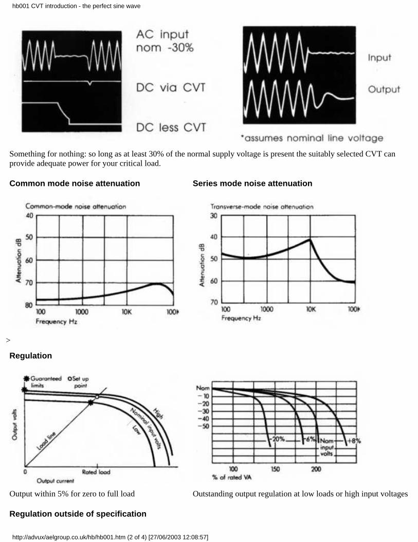


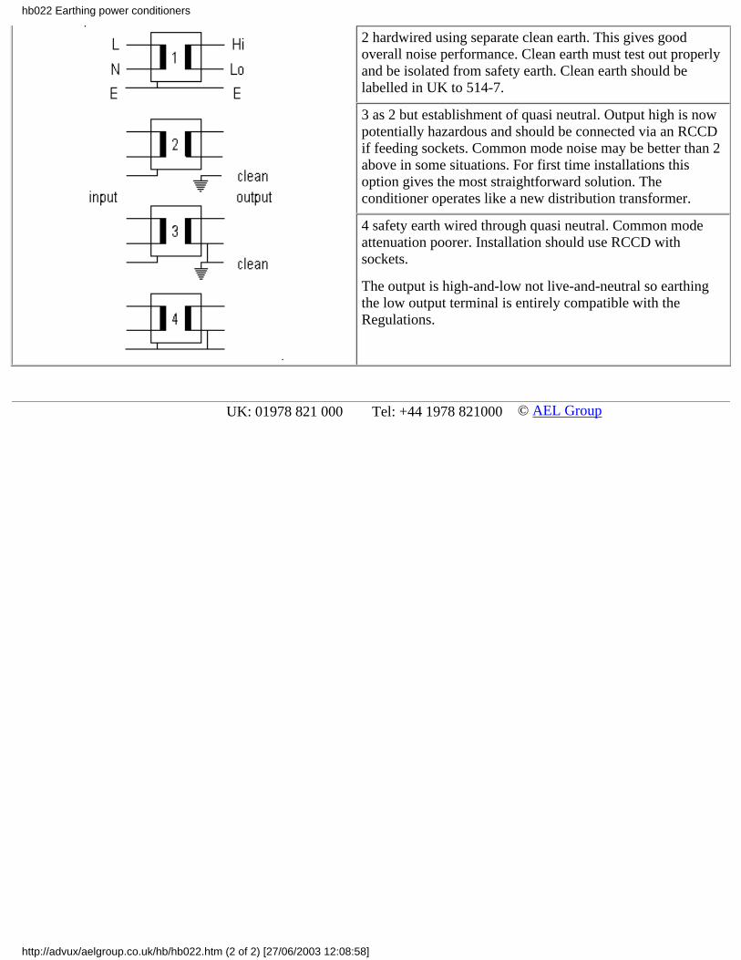


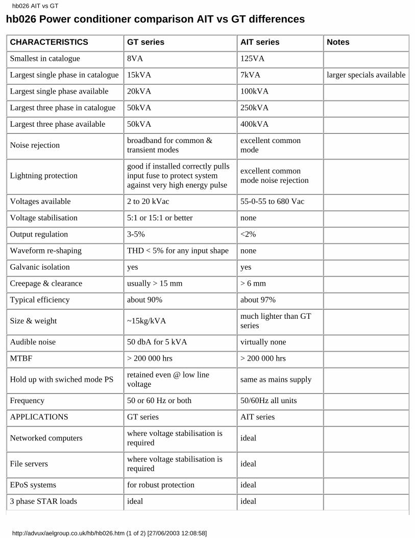


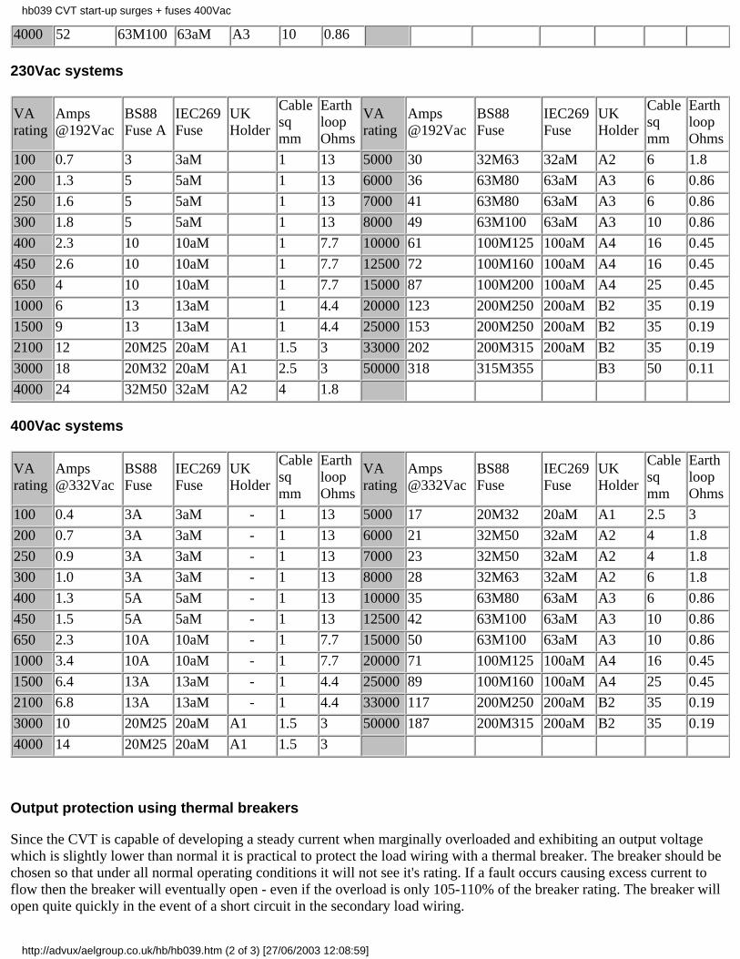


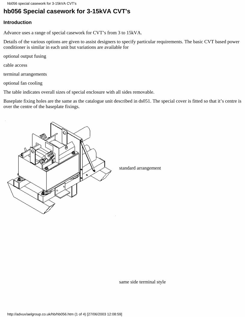


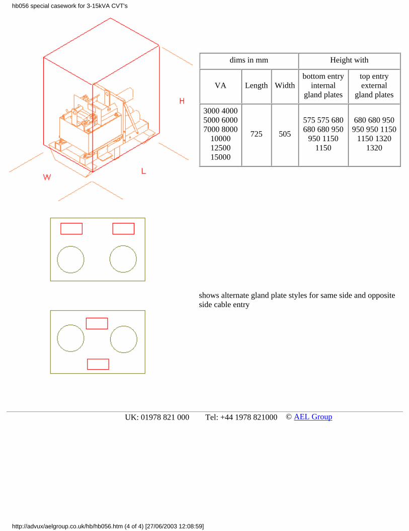


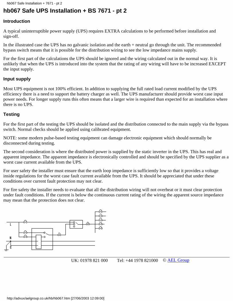


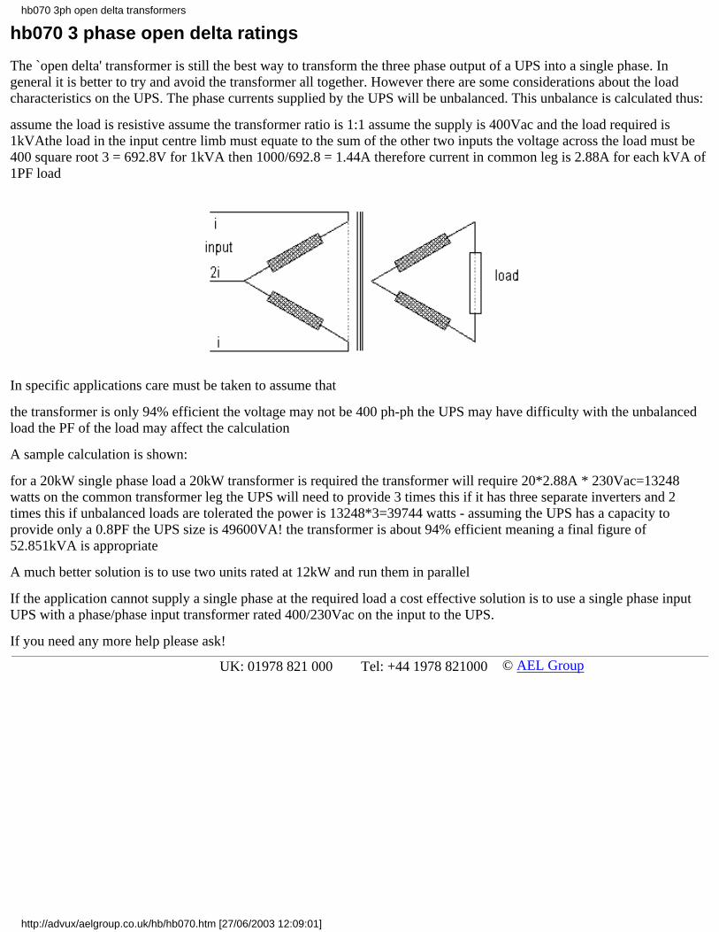


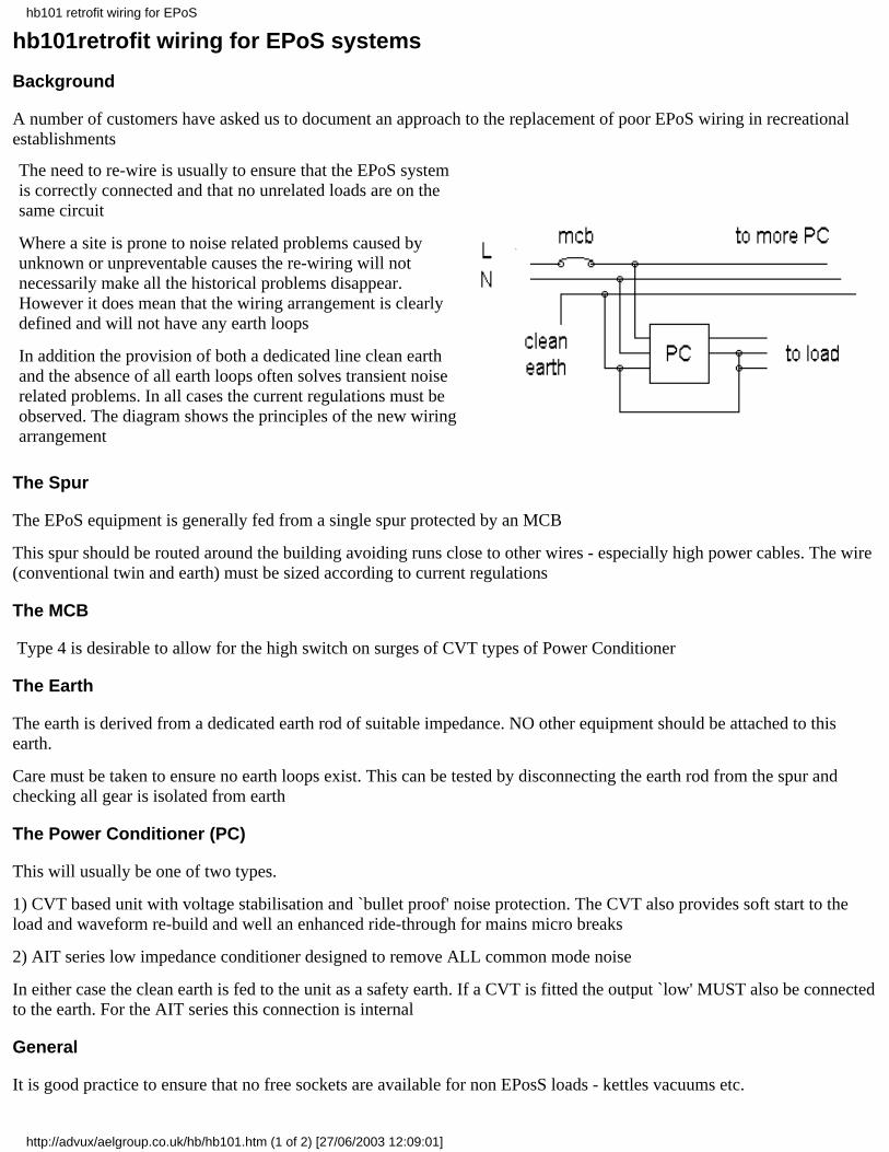


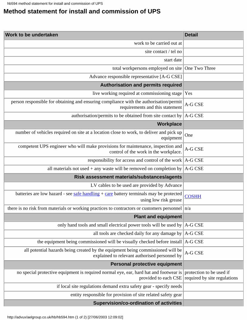


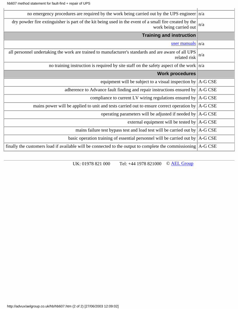


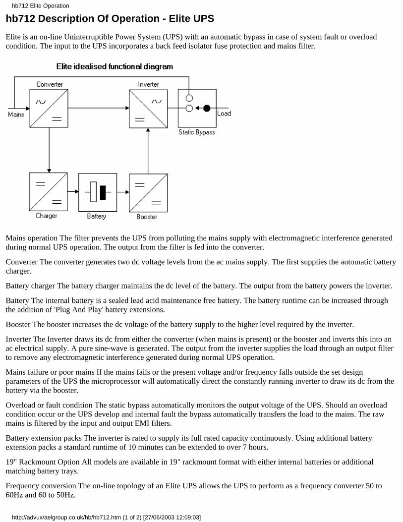


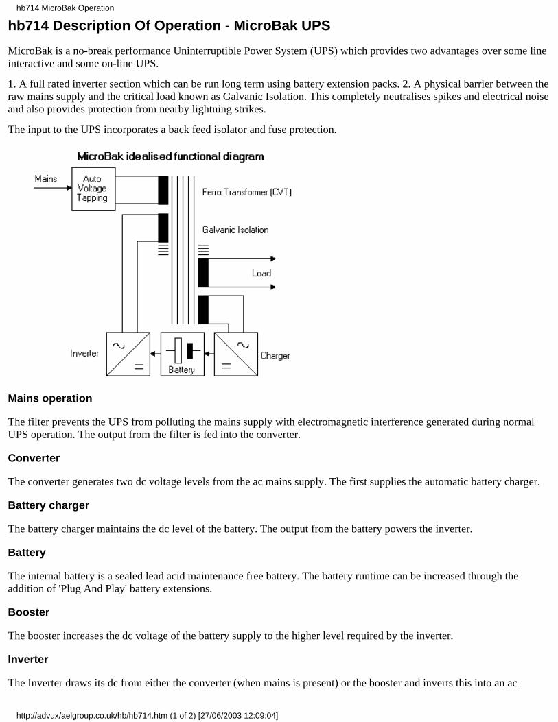

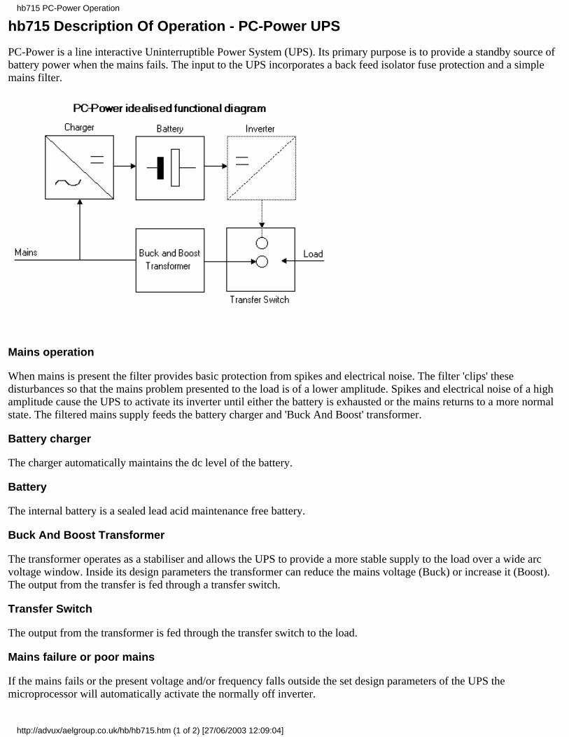


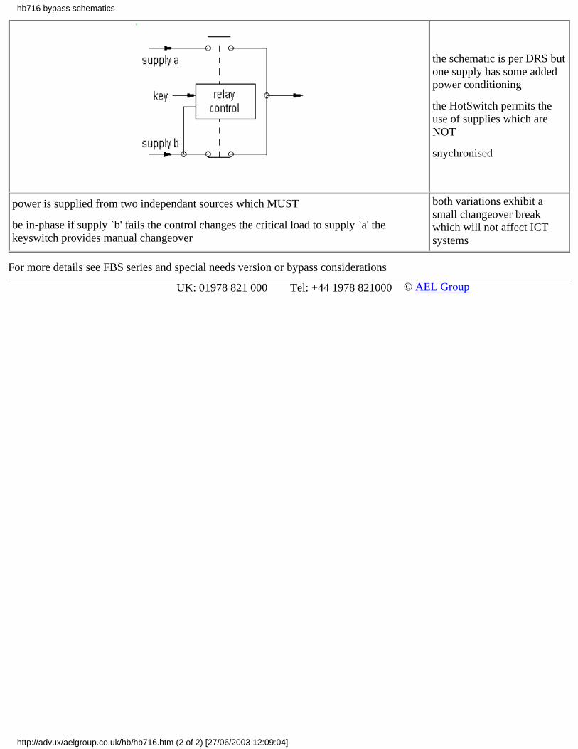

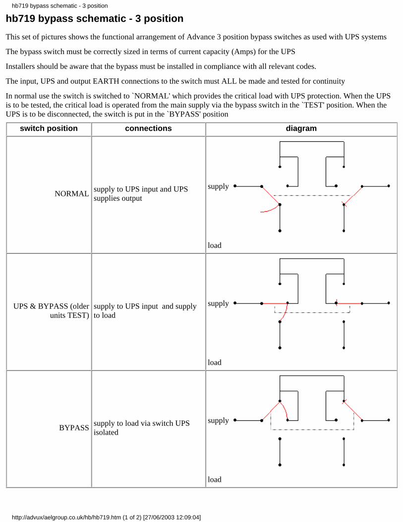


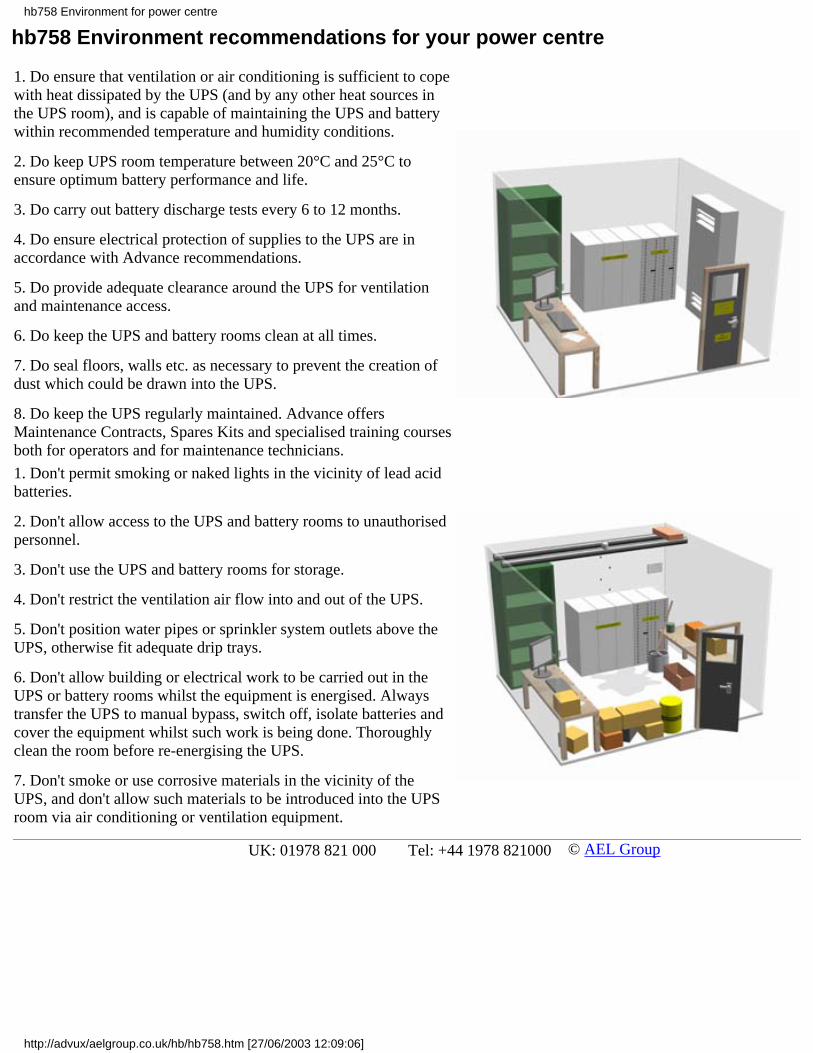
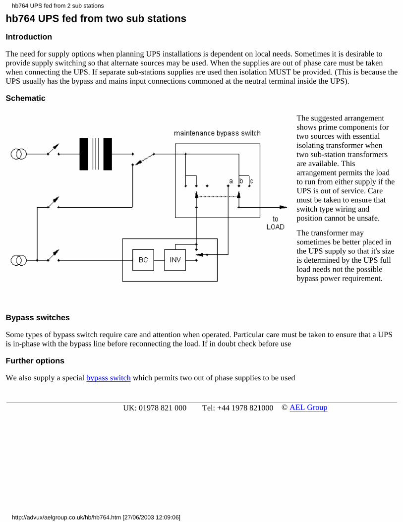


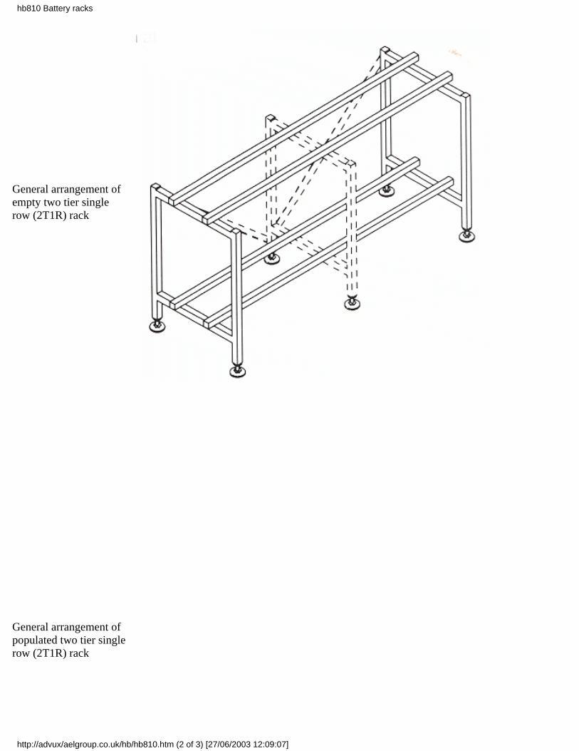

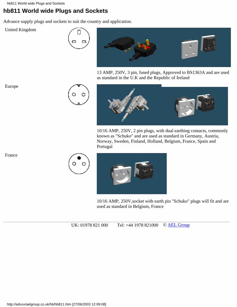


![BS 7671:2008+A3:2015 MODEL FORMS - Electrical …clarvis.co.uk/engres/forms.pdfELECTRICAL INSTALLATION CERTIFICATE (REQUIREMENTS FOR ELECTRICAL INSTALLATIONS - BS 7671 [IETWIRING REGULATIONS])](https://static.documents.pub/doc/80x56/5af738617f8b9a92719153b7/bs-76712008a32015-model-forms-electrical-installation-certificate-requirements.jpg)


