50

Page 2
HC REFRIGERANT PRODUCTSTRAINING MANUAL
ACKNOWLEDGEMENTS:
HYDROCARBON TECHNOLOGY IIGTZ Yearbook 1996Dr. Klaus MeyersenPeter Stormer, PhDDirk [email protected], 1996
All quotes in the manual are taken from:GUIDELINES FOR THE USE OF HYDROCARBON REFRIGERANTS IN STATIC REFRIGERATION AND AIRCONDITIONING SYSTEMSACRIBwww.acrib.org.uk
Revision 320041
www.hcrefrigerant.com

Page 3
TRAINING MANUAL * HC Refrigerant Products* Table of Contents
SECTION 1 PAGE SECTION 4 - TABLES PAGEREFRIGERANT ISSUES 4 HC-12aRefrigerant selection 4 Suction Line 27Refrigerant Properties 5 Evaporator Capacity Table 27Lubricants 6 Evaporator Capacity Correction Factors 27Materials 6 Minimum Refrigeration Capacity 28General System Components 7 Liquid Line Data 28
SECTION 2 Evaporator Capacity Table 28SAFETY 8 Evaporator Capacity Correction Factors 29General Issues 8 Discharge Line Data 29Allowable Refrigerant Charge 8 Evaporator Capacity Table 29Flammable Properties 9 Evaporator Capacity Correction Factors 29Safety Standards & Code of Practice 9 SECTION 5Design 10 HC-22a
Refrigerant Charge 10 Suction Line 30HC Refrigerant Equivalents 11 Evaporator Capacity Table 30
Categories 13 Evaporator Capacity Correction Factors 30Construction 13 Minimum Refrigeration Capacity 31
Use of Components 14 Liquid Line Data 31Installation 15 Evaporator Capacity Table 31
General 15 Evaporator Capacity Correction Factors 31Refrigerant Piping 15 Discharge line Data 32Machinery rooms 16 Evaporator Capacity 32
Ventilation 16 Evaporator Capacity Correction Factors 32Refrigerant Detection 17 SECTION 6
Sources of Ignition 18 HC-502aPipe Work Installation 18 Suction Line 33
Marking & Instruction 19 Evaporator Capacity Table 33General Considerations 19 Evaporator Capacity Correction Factors 33
SECTION 3 Minimum Refrigeration Capacity 34Liquid Line Data 34SERVICE, MAINTENANCE &
REFRIGERANT HANDLING 20 Evaporator Capacity Table 34Practical Competence 20 Evaporator Capacity Correction Factors 34General Approach to Handling 20 Discharge line Data 35Safety Checks 20 Evaporator Capacity 35
Checks to the Area 20 Evaporator Capacity Correction Factors 35Checks to the Equipment 21 OTHER TABLES
Checks to Electrical Devices 21 VAPOR PRESSURE VS. TEMPERATURE 36,41,46Initial Safety Checks 22 HC-12a Bubble Point (Standard) 37
Detection of Hydrocarbon Refrigerants 22 HC-12a Dew Point (Standard) 38Breaking into a System & Charging 23 HC-12a Bubble Point (Metric) 39
Charging 23 HC-12a Dew Point (Metric) 40Commissioning 24 HC-22a Bubble Point (Standard) 42
Decommissioning 24 HC-22a Dew Point (Standard) 43Recovery 24 HC-22a Bubble Point (Metric) 44
Handling of Cylinders 25 HC-22a Dew Point (Metric) 45Transportation of Cylinders 25 HC-502a Bubble Point (Standard) 47Storage of Cylinders 26 HC-502a Dew Point (Standard) 48Carriage of Systems 26 HC-502a Bubble Point (Metric) 49
HC-502a Dew Point (Metric) 50

Page 4
Section 1REFRIGERATION ISSUES
hile the most notable aspects associated with hydrocarbon refrigerant system designs are safety matters,general refrigeration issues should also be considered. These include Thermodynamic Properties, MaterialCompatibility and Component Selection.”
1.1 Refrigerant Selection
Standard Selection Criteria:1. Match refrigerant vapor pressures to operating conditions.2. Creation of good system efficiency.
Blended Refrigerants:1. Selected when the effect of temperature glide and composition shift is not an issue
Table 1.1 provides a general guide and comparison for refrigerant selection and application ranges. For moreinformation regarding refrigerant selection, please contact the HC Refrigerant Products Technical Supportrepresentative.
Table 1.1: Application ranges for HC Refrigerant ProductsRefrigerant Application Range Replacement
HC-12a High/Medium temperature; domestic appliances; automotive R12R134a
HC-22a High/Medium temperature; commercial; reefer R22R407cR410aR411a
HC-502a Medium/low temperature; commercial; industrial; industrial processrefrigeration; chillers; reefer
R502R404aR408aR507a
Use refrigerant grade products only.“Commercial grade hydrocarbons contain significant quantities of water and other impurities and could contribute tooil degradation and shorten the compressor life. Another problem with commercial LPG is that the composition ofany specific hydrocarbon can be variable thus drastically changing the properties of the refrigerant from cylinder tocylinder.”
“W

Page 5
1.2 Refrigerant Properties
The physical properties of a refrigerant determine its application. The predictions of system behavior and performance are aided by the knownThermodynamic and Transport properties of the refrigerant. Table 1.2 shows basic properties. Please consult the MSDS for more comprehensive information,or contact the HC Refrigerant Products Technical Support Representative.
Table 1.2: Physical Properties of Refrigerant (Metric and Standard)
PHYSICAL PROPERTIES OF REFRIGERANT – METRICRefrigerant Density of Liquid
@ 30°C(Mg/m3)
Boiling Point @1 Atmosphere
(°C)
CriticalTemperature
(°C)
CriticalPressure
(kPa)
TemperatureGlide @
25°C
Latent Heat ofVaporization @Boiling Point
(kJ/kg)
Density ofSaturated Vapor @
Boiling Point(kg/m3)
R12 1.29 -29.8 112.0 4015 0 165 6.3R22 1.17 -40.8 96.1 4877 0 233 4.7R502 1.19 -45.4 82.2 3974 <1.0 172 6.2HC-12a 0.517 -32.6 113.0 3989 6 405 1.9HC-22a 0.484 -44.6 96.7 4248 0 426 2.4HC-502a 0.475 -49.8 93.5 4280 2 444 1.8
PHYSICAL PROPERTIES OF REFRIGERANT - STANDARDRefrigerant Density of Liquid
@ 90°F (lb/ft3)Boiling Point @1 Atmosphere
(°F)
CriticalTemperature
(°F)
CriticalPressure
(psig)
TemperatureGlide @
77°F
Latent Heat ofVaporization @Boiling Point
(Btu/lb)
Density of Saturated Vapor@ Boiling Point
(lb/ft)R12 80.12 -21.6 234 582 0 71.5 0.39R22 72.52 -41.4 205 707 0 101.0 0.29R502 73.49 -49.7 180 576 <1.0 74.6 0.38HC-12a 31.9 -24.7 235 579 6 177.0 0.12HC-22a 29.9 -43.8 206 616 0 186.0 0.15HC-502a 29.6 -56.2 200 621 2 191.0 0.12
Page 6
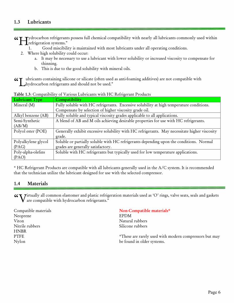
1.3 Lubricants
ydrocarbon refrigerants possess full chemical compatibility with nearly all lubricants commonly used withinrefrigeration systems.”1. Good miscibility is maintained with most lubricants under all operating conditions.
2. Where high solubility could occur:a. It may be necessary to use a lubricant with lower solubility or increased viscosity to compensate for
thinning.b. This is due to the good solubility with mineral oils.
ubricants containing silicone or silicate (often used as anti-foaming additives) are not compatible withhydrocarbon refrigerants and should not be used.”
Table 1.3: Compatibility of Various Lubricants with HC Refrigerant ProductsLubricant Type CompatibilityMineral (M) Fully soluble with HC refrigerants. Excessive solubility at high temperature conditions.
Compensate by selection of higher viscosity grade oil.Alkyl benzene (AB) Fully soluble and typical viscosity grades applicable to all applications.Semi-Synthetic(AB/M)
A blend of AB and M oils achieving desirable properties for use with HC refrigerants.
Polyol ester (POE) Generally exhibit excessive solubility with HC refrigerants. May necessitate higher viscositygrade.
Polyalkylene glycol(PAG)
Soluble or partially soluble with HC refrigerants depending upon the conditions. Normalgrades are generally satisfactory.
Poly-alpha-olefins(PAO)
Soluble with HC refrigerants but typically used for low temperature applications.
* HC Refrigerant Products are compatible with all lubricants generally used in the A/C system. It is recommendedthat the technician utilize the lubricant designed for use with the selected compressor.
1.4 Materials
irtually all common elastomer and plastic refrigeration materials used as ‘O’ rings, valve seats, seals and gasketsare compatible with hydrocarbon refrigerants.”
Compatible materials Non-Compatible materials*Neoprene EPDMViton Natural rubbersNitrile rubbers Silicone rubbersHNBRPTFENylon
*These are rarely used with modern compressors but maybe found in older systems.
“H
“L
“V

Page 7
1.5 General System Components
ypically, system components used for fluorocarbon refrigerants do not differ significantly when usinghydrocarbons. Component suppliers should be consulted regarding other in-line components such as pressureregulators, solenoid valves, etc.”
vaporators and condensers“Evaporators and condensers using hydrocarbons tend to be virtually the same design and size as those used forconventional fluorocarbon refrigerants that operate at similar pressures. Heat transfer coefficients tend to be
higher for most hydrocarbons but this does not significantly affect heat exchanger dimensions. All common types ofheat exchangers are suitable for use with hydrocarbon-based refrigerants including:
• Air coiled• Shell and tube (flooded and direct expansion)• Plate heat exchangers
Suction-Liquid heat exchangers should also be considered since they contribute to improved system efficiencyespecially when using hydrocarbons”
ompressors“Most compressor types are suitable for use with hydrocarbon refrigerants and compressor suppliers should beconsulted for application and selection. Using a compressor with hydrocarbons without the supplier’s approval
may invalidate the warranty.”
“In order to secure satisfactory performance, long life, and to protect the compressor against overload, certain designcriteria should be observed. Compressor application notes and data should always be consulted when designing asystem. Ensure compressors are clearly labeled to indicate that hydrocarbon refrigerants are being used in the system.The use of crankcase heaters should be considered to avoid excessive oil solubility.”
efrigerant Control DevicesAll expansion device types are suitable for use with HC Refrigerants. “Design and selection criteria are the
same as those for conventional fluorinated refrigerants. Computer programs and tables are available fordetermining capillary tube size and length, although trial and error is generally the preferred route.Thermostatic Expansion Valves (TEV) for other refrigerants that operate with similar pressure-temperaturerelationships can be used. Electronic Expansion Valves (EEV) may also be used. EEV’s used in HC refrigerantsystems must conform to the requirements of electrical components as detailed in Section 2.6.6.”
esiccants“Desiccants are used within filter dryers. Most commonly used desiccants are compatible with hydrocarbonrefrigerants. Acceptable types are XH-5, XH-6 or equivalent.”
ipe Size Selection“When selecting refrigerant line sizes, specific hydrocarbon refrigerant pipe sizing literature should be used.Despite most hydrocarbon refrigerants having similar operating pressures to the ‘equivalent’ fluorocarbon
refrigerants, thermodynamic and transport properties can differ significantly, thus data for other refrigerants will notbe directly applicable. Refrigerant supplies should provide the appropriate pipe size selection data.”
“T
E
C
R
D
P
Page 8
SECTION 2SAFETY
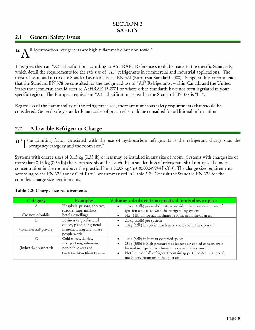
2.1 General Safety Issues
ll hydrocarbon refrigerants are highly flammable but non-toxic.”
This gives them an “A3” classification according to ASHRAE. Reference should be made to the specific Standards, which detail the requirements for the safe use of “A3” refrigerants in commercial and industrial applications. The most relevant and up to date Standard available is the EN 378 (European Standard 2000). Sunpoint, Inc. recommends that the Standard EN 378 be consulted for the design and use of “A3” Refrigerants, within Canada and the United States the technician should refer to ASHRAE 15-2001 or where other Standards have not been legislated in your specific region. The European equivalent “A3” classification as used in the Standard EN 378 is “L3”.
Regardless of the flammability of the refrigerant used, there are numerous safety requirements that should beconsidered. General safety standards and codes of practiced should be consulted for additional information.
2.2 Allowable Refrigerant Charge
he Limiting factor associated with the use of hydrocarbon refrigerants is the refrigerant charge size, theoccupancy category and the room size.”
Systems with charge sizes of 0.15 kg (0.33 lb) or less may be installed in any size of room. Systems with charge size ofmore than 0.15 kg (0.33 lb) the room size should be such that a sudden loss of refrigerant shall not raise the meanconcentration in the room above the practical limit 0.008 kg/m (0.00049944 lb/ft). The charge size requirementsaccording to the EN 378 annex C of Part 1 are summarized in Table 2.2. Consult the Standard EN 378 for thecomplete charge size requirements.
Table 2.2: Charge size requirements
Category Examples Volumes calculated from practical limits above up to:A
(Domestic/public)
Hospitals, prisons, theatres,schools, supermarkets,hotels, dwellings.
• 1.5kg (3.3lb) per sealed system provided there are no sources ofignition associated with the refrigerating system
• 5kg (11lb) in special machinery rooms or in the open airB
(Commercial/private)
Business or professionaloffices, places for generalmanufacturing and wherepeople work.
• 2.5kg (5.5lb) per system• 10kg (22lb) in special machinery rooms or in the open air
C
(Industrial/restricted)
Cold stores, dairies,meatpacking, refineries,non-public areas ofsupermarkets, plant rooms.
• 10kg (22lb) in human occupied spaces• 25kg (55lb) if high pressure side (except air cooled condenser) is
located in a special machinery room or in the open air• Not limited if all refrigerant containing parts located in a special
machinery room or in the open air
“A
“T

Page 9
2.3 Flammable Properties
able 2.3 provides property data relevant to HC refrigerants. These values are necessary in the design stagewhen determining maximum refrigerant charge, ventilation, flow rates and maximum allowable temperaturesof components.”
Table 2.3: Flammability properties for selected HC refrigerants
Refrigerant Lower Flammability Limit (LFL) Auto IgnitionTemp
By volume (%) By mass (kg/m) (lb/ft)HC-12a® 1.95 0.040 0.002497 891ºC (1636ºF)HC-22a® 2.0 0.038 0.002372 480ºC (896ºF)HC-502a® 2.2 0.038 0.002372 472ºC (882ºF)
The practical limit as defined in the EN 378 is 20% of the LFL.
2.4 Safety Standards and Code of Practice
“There are a number of codes and safety standards that are appropriate to the use of HC refrigerants and related equipment. The selection of appropriate documents is not always obvious and thereforethe objective of this section is to provide a degree of clarity in this area.”
Generally, refrigeration systems should be designed and constructed in accordance with the general safetyrequirements for A3/L3 refrigerants. These are detailed in various regional (Provincial, State or Municipal) codes. Itis the responsibility of the Air Conditioning or Refrigeration Engineer/Contractor to know and understand therestrictions governing the use of A3/L3 refrigerants and to follow the guidelines accordingly.
The most fundamental difference between systems using flammable refrigerants and non-flammable refrigerants isa) the volume allowances per square footage andb) the use of suitable electrical equipment that will not pose a risk in the event of a release.
It is expected that engineers/contractors involved in the design, construction and maintenance of refrigeration systemsbe competent and up to date with training.
NOTE: Domestic and small hermetic type refrigeration systems often have other safety issues such as electricregulations related to them since they are considered as appliances. Please consult the safety requirements specific tosmall appliances when installing.
Standards are not exhaustive in their requirements and if a safe system of work can demonstrate an equal level of safetyas that implied by the standard and satisfy Canadian or American legislation, then this approach is equally acceptable.Indeed Notified Bodies often set their own construction and test criteria when standards are not yet available orexisting standards are not considered appropriate for use.
“T

Page 10
2.5 Design
Specific design requirements are generally applied to a system based on the refrigerant charge size and location.
The following pages contain an explanation of the rules governing equipment design.
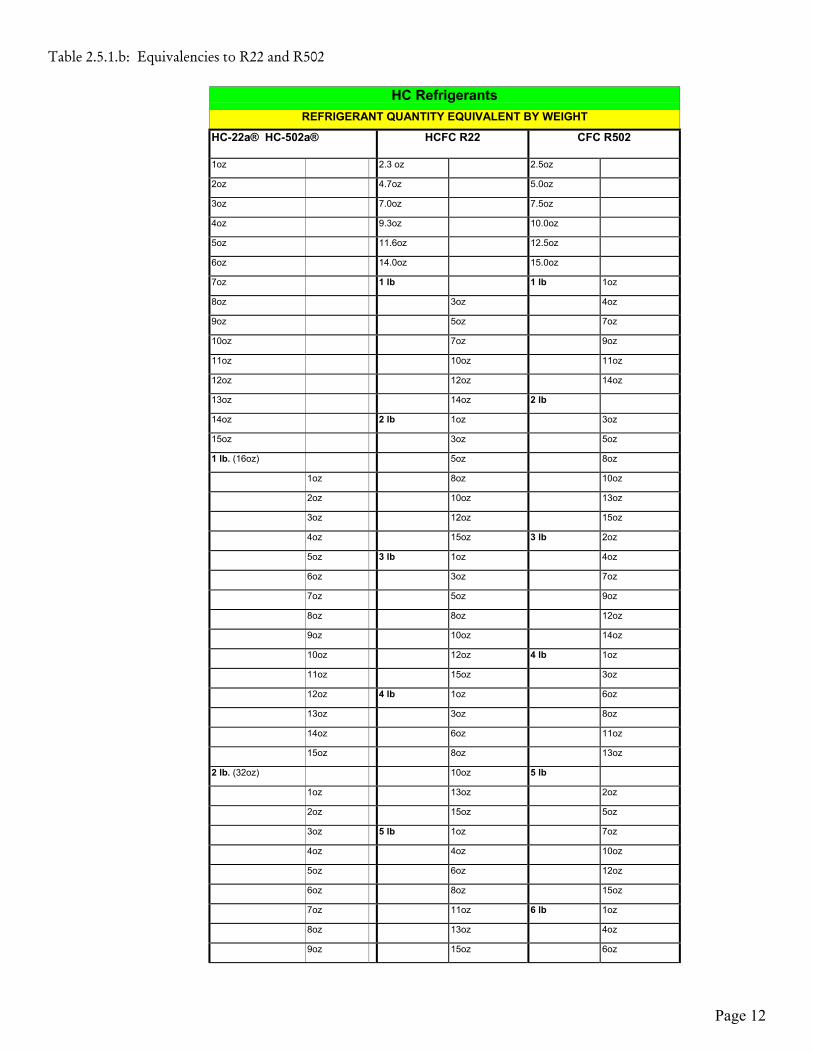
2.5.1 Refrigerant Charge
Below are the equivalencies of hydrocarbon refrigerants versus CFC and HCFC system charges. Under nocircumstances should the system be overcharged. It is important to note that because the density of HC refrigerantsare much lower, during charging the volume of HC Refrigerant is basically equivalent to double the volume of theCFC or HCFC’s. Therefore, overcharged systems pose dramatic differences in terms of the kPa (psig) increases andcould therefore potentially damage systems or components.
Please refer to pages 8 & 9 for Table 2.5.1.a representing equivalencies to R12 and R134a and Table 2.5.1.b.

Page 11
Table 2.5.1.a: Equivalencies to R12 and R134a
HC-12a® RefrigerantREFRIGERANT QUANTITY EQUIVALENT BY WEIGHT
HC-12a® HFC R134a CFC R12
1 oz 2.5 oz 2.8 oz
2 oz 5.0 oz 5.7 oz
3 oz = 1/2 can 7.5 oz 8.5 oz
4 oz 10 oz 11.4 oz
5 oz 12.5 oz 14.2 oz
6 oz = 1 can 15 oz 17 oz
7 oz 1 lb. 1 oz 1lb. 4 oz
8 oz 4 oz 6 oz
9 oz = 1 ½ cans 6 oz 9 oz
10 oz 9 oz 12 oz
11 oz 11 oz 15 oz
12 oz = 2 cans 14 oz 2 lb. 2 oz
13 oz 2 lb. 5 oz
14 oz 3 oz 8 oz
15 oz = 2 ½ cans 5 oz 10 oz
1 lb. (16 oz) 8 oz 13 oz
1 oz 10 oz 3 lb.
2 oz = 3 cans 13 oz 3 oz
3 oz 15 oz 6 oz
4 oz 3 lb. 2 oz 9 oz
5 oz = 3 ½ cans 3 oz 12 oz
6 oz 7 oz 14 oz
7 oz 9 oz 4 lb. 1 oz
8 oz = 4 cans 12 oz 4 oz
9 oz 14 oz 7 oz
10 oz 4 lb. 1 oz 10 oz
11 oz = 4 ½ cans 3 oz 13 oz
12 oz 6 oz 5 lb.
13 oz 8 oz 2 oz
14 oz = 5 cans 11 oz 5 oz
15 oz 13 oz 8 oz
2 lb. 5 lb. 11 oz
1 oz = 5 ½ cans 2 oz 14 oz
2 oz 5 oz 6 lb. 1 oz
3 oz 7 oz 4 oz
4 oz = 6 cans 10 oz 6 oz
5 oz 12 oz 9 oz
6 oz 14 oz 12 oz
7 oz = 6 ½ cans 6 lb. 1 oz 15 oz
8 oz 4 oz 7 lb. 2 oz
9 oz 6 oz 5 oz
10 oz = 7 cans 9 oz 8 oz
11 oz 11 oz 10 oz
Page 12
Table 2.5.1.b: Equivalencies to R22 and R502
HC RefrigerantsREFRIGERANT QUANTITY EQUIVALENT BY WEIGHT
HC-22a® HC-502a® HCFC R22 CFC R502
1oz 2.3 oz 2.5oz
2oz 4.7oz 5.0oz
3oz 7.0oz 7.5oz
4oz 9.3oz 10.0oz
5oz 11.6oz 12.5oz
6oz 14.0oz 15.0oz
7oz 1 lb 1 lb 1oz
8oz 3oz 4oz
9oz 5oz 7oz
10oz 7oz 9oz
11oz 10oz 11oz
12oz 12oz 14oz
13oz 14oz 2 lb
14oz 2 lb 1oz 3oz
15oz 3oz 5oz
1 lb. (16oz) 5oz 8oz
1oz 8oz 10oz
2oz 10oz 13oz
3oz 12oz 15oz
4oz 15oz 3 lb 2oz
5oz 3 lb 1oz 4oz
6oz 3oz 7oz
7oz 5oz 9oz
8oz 8oz 12oz
9oz 10oz 14oz
10oz 12oz 4 lb 1oz
11oz 15oz 3oz
12oz 4 lb 1oz 6oz
13oz 3oz 8oz
14oz 6oz 11oz
15oz 8oz 13oz
2 lb. (32oz) 10oz 5 lb
1oz 13oz 2oz
2oz 15oz 5oz
3oz 5 lb 1oz 7oz
4oz 4oz 10oz
5oz 6oz 12oz
6oz 8oz 15oz
7oz 11oz 6 lb 1oz
8oz 13oz 4oz
9oz 15oz 6oz

Page 13
2.5.2 CategoriesAs defined by the EN 378, the following Occupancy categories require attention to the allowable charge and theprovisions for each individual category.Occupancy types as defined under EN 378 Standard are:
(A) – Rooms, parts of buildings or buildings where people may sleep, people are restricted in their movements or anuncontrolled number of people are present or to which any person has access without being personally acquaintedwith the necessary safety precautions.
(B) – Rooms, parts of buildings, buildings where only a limited number of people may be assembled, some beingnecessarily acquainted with the general safety precautions of the establishment.
(C) –Rooms, parts of buildings, buildings where only authorized persons have access, who are acquainted with generaland special safety precautions of the establishment and where manufacturing, processing or storage of material orproducts take place.
Where there is the possibility of more than one category of occupancy, the more stringent requirements apply. Ifoccupancies are isolated, e.g. by sealed partitions, floors and ceilings, in which case the requirements of the individualcategory of occupancy apply.
NOTE: Attention is drawn to the safety of adjacent premises and occupants in areas adjacent to arefrigerating system. Refrigerants heavier than air can cause oxygen deficient pockets at lower levels.
2.5.3 ConstructionIf the charge is more than .15 kg (0.33 lb), then a sudden loss of refrigerant should not raise the mean concentration inthe room above the practical limit 0.008 kg/m3 (0.0004994 lb/ft3 ). The room volume governs the total charge size.This can be determined by the equation 2.5.3.a.
Mr = 0.2 ∙ (LFL) ∙ Vroom (Equation 2.5.3.a)Where:Mr = maximum allowable refrigerant charge per separate refrigerant circuit (kg or lb) Vroom = room volume (m3 or ft3)LFL = lower flammability limit of refrigerant (kg/m3 or lb/ft3) from table 2.3
Similarly, the minimum room volume for a specific refrigerant charge is determined by the equation 2.5.3.b.
Vroom = (Equation 2.5.3.b)
Mr
0.2 ∙ (LFL)
In practical terms, for a 100m3 (3531 ft3) of room volume, the maximum allowable charge would be 760 g (27 oz) ofHC-22a® per refrigerant circuit. Charges in systems below ground (i.e. cellars and basements) are restricted to amaximum of 1.0 kg (2.2 lb) even with larger room sizes. Sealed systems containing a charge of less than 150 g (5.3 oz)can be situated in any location, regardless of room volume.
Note that all charge limits apply per single refrigerant circuit, on the basis of probability that two circuits will nothave catastrophic failures simultaneously.Avoidance of Stratification In the event of a “catastrophic” leak it is possible that stratification of refrigerant can occur, resulting in the formationof flammable concentrations at lower levels. In order to prevent this from occurring the fan associated with the

Page 14
refrigerating system should be able to provide a minimum airflow, as detailed in the equation 2.5.3.c. It is suggestedthat the fan operate only during the compressor on-cycle since the probability of a catastrophic leak during the off-cycle is negligible, or ensure the fan is connected to an interlock that would be activated only when the detection of aleak is evident.
Vair = C ∙ (Equation 2.5.3.c)
Mr
(LFL)
Where:Vair = minimum air flow rate from the fan m3 /h (ft3 /h)The constant, C depends upon the origin of the airflow:C = 17 when the evaporator fan on an air conditioning unit is providing the air flow into the room or,C = 20 when the condenser fan on a refrigerating unit is providing the air flow into the room.
The different constants result from the effectiveness of fan mixing, primarily due to the velocity of the discharged air.
Maximum Refrigerant Charge The maximum allowable refrigerant charge for specific installation types, subject to other requirements is as outlinedin the Standards as defined by the location of the installation. We recommend that the European Standard EN 378 beconsulted where relevant Provincial, Municipal or State Standards have not been legislated in your region.
Combustible Materials Materials used to construct the refrigerating system should not be combustible.
2.5.4 Use of Components
Vibration Elimination“If the equipment is solidly mounted then vibration eliminators to the suction and discharge lines should not, undernormal circumstances, be required. If the compressor is mounted on rubber or spring mounts it may be advisable toinstall vibration eliminators to the suction and discharge line.”
Pressure ReliefDepending on the type of system and charge size some systems must use some type of pressure relief device but notonly a fusible plug. When required it is preferable to use an automatic pressure relief valve on the high side, vented tothe low side before other pressure relief devices discharge refrigerant to the atmosphere. The European Standard EN378 should be consulted to identify the type and size of systems that require some pressure relief where relevantProvincial, Municipal or State Standards have not been legislated in your region.
Pressure SwitchesDepending on the type of system and charge size some systems must use low and high pressure switches located on thesuction and discharge sections of the system. The European Standard EN 378 should be consulted to identify the typeand size of systems that require pressure switches where relevant Provincial, Municipal or State Standards have notbeen legislated in your region.
Pipe Connections Flanged joints are preferred to flared, screwed or compression type joints. For non-detachable joints soldering,welding or brazing shall be used.
Page 15
Other System Components Other system mechanical components such as pressure vessels, compressors, heat exchangers, piping and fittingsshould conform to the requirements of the relevant standards.
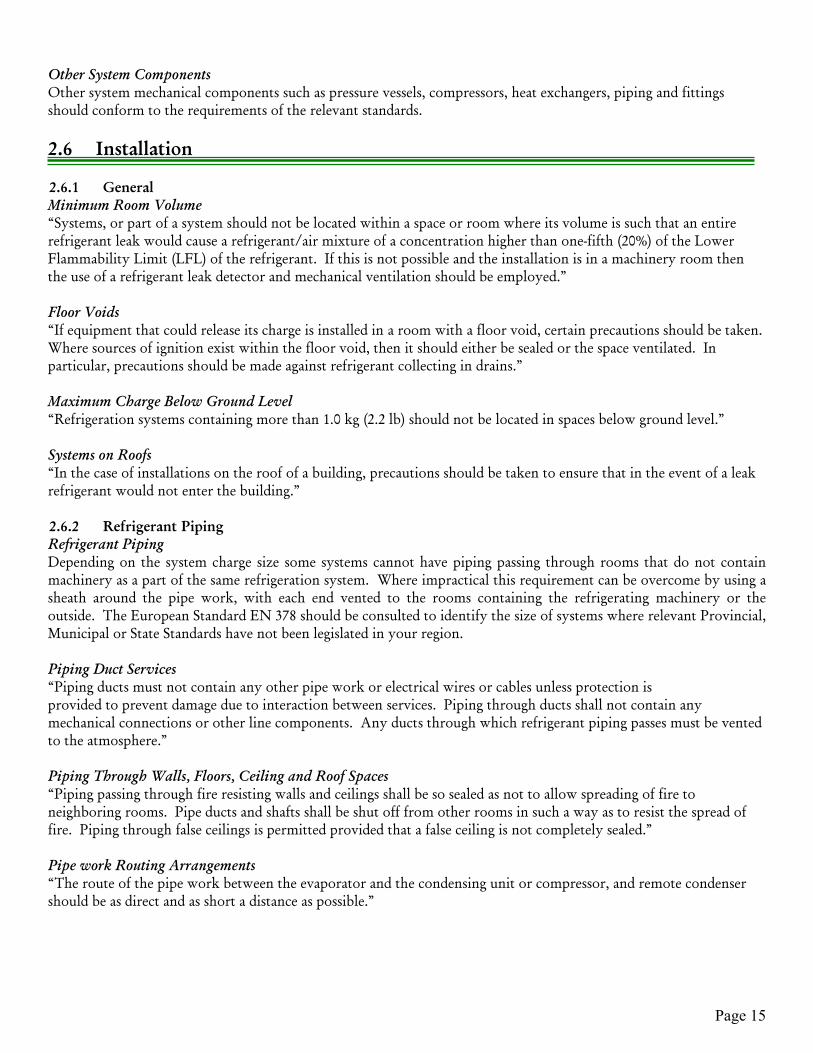
2.6 Installation
2.6.1 GeneralMinimum Room Volume “Systems, or part of a system should not be located within a space or room where its volume is such that an entirerefrigerant leak would cause a refrigerant/air mixture of a concentration higher than one-fifth (20%) of the LowerFlammability Limit (LFL) of the refrigerant. If this is not possible and the installation is in a machinery room thenthe use of a refrigerant leak detector and mechanical ventilation should be employed.”
Floor Voids “If equipment that could release its charge is installed in a room with a floor void, certain precautions should be taken.Where sources of ignition exist within the floor void, then it should either be sealed or the space ventilated. Inparticular, precautions should be made against refrigerant collecting in drains.”
Maximum Charge Below Ground Level“Refrigeration systems containing more than 1.0 kg (2.2 lb) should not be located in spaces below ground level.”
Systems on Roofs“In the case of installations on the roof of a building, precautions should be taken to ensure that in the event of a leakrefrigerant would not enter the building.”
2.6.2 Refrigerant PipingRefrigerant PipingDepending on the system charge size some systems cannot have piping passing through rooms that do not containmachinery as a part of the same refrigeration system. Where impractical this requirement can be overcome by using asheath around the pipe work, with each end vented to the rooms containing the refrigerating machinery or theoutside. The European Standard EN 378 should be consulted to identify the size of systems where relevant Provincial,Municipal or State Standards have not been legislated in your region.
Piping Duct Services “Piping ducts must not contain any other pipe work or electrical wires or cables unless protection isprovided to prevent damage due to interaction between services. Piping through ducts shall not contain anymechanical connections or other line components. Any ducts through which refrigerant piping passes must be ventedto the atmosphere.”
Piping Through Walls, Floors, Ceiling and Roof Spaces“Piping passing through fire resisting walls and ceilings shall be so sealed as not to allow spreading of fire toneighboring rooms. Pipe ducts and shafts shall be shut off from other rooms in such a way as to resist the spread offire. Piping through false ceilings is permitted provided that a false ceiling is not completely sealed.”
Pipe work Routing Arrangements“The route of the pipe work between the evaporator and the condensing unit or compressor, and remote condensershould be as direct and as short a distance as possible.”

Page 16
Water Circuits “For systems using an indirect cooling circuit, there is a possibility of accidental release of refrigerant into thesecondary circuit from a rupture of the evaporator or condenser wall. This should be dealt with by one of thefollowing options:
Incorporate an air vent/air separator within the secondary circuit, on the outlet pipe from the evaporator orcondenser. Ensure that it is adequately sized such that it will release any refrigerant back into the housing,machinery room, special area or to the outside. This release can then be dealt with as any normal refrigerantrelease from the primary circuit.
Use a ‘double-walled’ heat exchanger, of the type that is laser-welded, designed such that it can only vent toatmosphere rather than the secondary circuit in the event of damage.”
2.6.3 Machinery Rooms“Machinery rooms for systems using HC refrigerants shall be designed to prevent the ignition of arefrigerant / air mixture. There should be warning notices stating that smoking, potential ignition sourcesor flames are prohibited. Fire extinguishers should be available and should provide clear instructions.”
“Machinery rooms must not be constructed out of combustible materials. If it is possible for theconcentration of refrigerant to reach the Lower Flammability Limit (LFL) then some explosion relief shouldbe provided in the construction of the machinery room. This may be in the form of movable panels orlouvers.”
Protect all refrigerant containing machinery so that damage from external sources would be difficult.
“NOTE: Although a machinery room does not necessarily serve exclusively for refrigeration equipment,boilers and other open flame devices should not share the space. Air intakes for equipment should not betaken from within the machinery room, or close to the machinery room ventilation outlet.”
As always, regional guidelines and standards should be consulted.
2.6.4 Ventilation“Refrigeration machinery rooms should be vented to the outside air by means of natural or mechanicalventilation.
Free Air Movement (All)“Ensure that free air movement can be achieved around all refrigerant containing parts of the system. Openings foroutside air should be positioned such that short circuiting does not occur.”
Mechanical Ventilation (All)Where the refrigerant charge of a single refrigerating circuit exceeds the mass in Equation 2.5.3.a, a machinery roomcontaining HC refrigerants must employ mechanical ventilation capable of providing the minimum ventilation rate.The minimum ventilation rate depends upon the type of electrical protection within the machinery room. Where theinstallation is protected according to Section 2.6.6 the mechanical ventilation rate should be equivalent to at least 10-room volume changes per hour.
Page 17
Where the electrical installation does not conform to Section 2.6.6 the minimum ventilation rate is defined byequation 2.6.4.a.
Vmin = (Equation 2.6.4.a)
Mr
tr ∙ (SF) ∙ (LFL)Where:Vmin = minimum volume flow rate of extract fan, m3 /hr (ft3 /hr).Mr = largest mass of refrigerant within any single circuit of any refrigerating system, kg (lb).tr = minimum release time of refrigerant following a catastrophic leak, typically 0.17 hr.SF = safety factor, 0.5.LFL = Lower Flammability Limit of refrigerant, kg/m3 (lb/ft3) from Table 2.3.
“In all cases a refrigerant detector should be linked into the initiation of mechanical ventilation. The location of thesampling point should be at low level (where heavier than air refrigerants are used). The ventilation must either berunning continuously or use a refrigerant detector starting device set at 20% of the Lower Flammability Level (LFL).Lower ventilation rates can be initiated upon detection of lower refrigerant concentrations.”
“The inlet of the extract ventilation should be located at floor level, and ducted to a safe location. Discharge points forvented air or openings for fresh air shall be positioned so as to avoid discharged air being drawn back in the buildingsuch as ventilation system inlets, opening windows and doors and sources of ignition. The rejection of flammablematerials shall not present a hazard externally, such as entering a building or being in contact with sources of ignition.The mechanical ventilation system should be designed to maintain the room at a lower pressure than surroundingareas so that there will be no escape of leaked refrigerants to other areas. Fans for mechanical ventilation should usemotors of non-sparking type and the fan blades and cowling should be designed so as to avoid sparking as a result ofmetal-to-metal contact. Mechanical ventilation equipment should be installed with independent emergency controllocated outside of and near to the machinery room.”
NOTE: To obtain a reduced airflow under non-emergency conditions, multi-speed fans may be used. Machinery rooms can also use natural ventilation provided that it is designed adequately. As always, regional guidelines and standards should be consulted.
2.6.5 Refrigerant Detection“Refrigerant vapor detectors should be provided in machinery rooms to activate an alarm and to automatically switchon ventilation fans if the concentration of refrigerant release exceeds the Practical Limit. Detectors should be used toisolate electrical equipment that does not conform to the electrical requirements detailed in Section 2.6.6, and to warnpersons that a release has occurred. Sampling points should be installed at strategic points within machinery rooms.Points should be located so that they provide rapid signals in the event of a leak, and that the effect of air movementdoes not inhibit their effectiveness. Refrigerant leak detectors shall be calibrated for the specific refrigerant they areintended to detect. Where the refrigerant is heavier than air, sampling points shall be located at floor level. TheEuropean Standard EN 378 should be consulted to identify the type of systems, size and location for detection whererelevant Provincial, Municipal or State Standards have not been legislated in your region.”
Page 18
2.6.6 Sources of IgnitionThere should be no sources of ignition as part of the refrigerating system or equipment.
Electrical ComponentsPrecautions should be taken to avoid the possibility of direct sources of ignition from exposed electrical contacts.Electrical items that have the potential to produce electrical sparks during normal operation should receive particularattention to eliminate them as potential sources of ignition. The following methods can be applied:
Insulate terminals Locate within appropriate enclosures Replace with solid state type components Replace with explosion proof components Locate externally
Providing such items only comprise of solid state parts or have casings which are solid encapsulated or otherwisesealed or are located externally to casing of the refrigerant containing parts then adequate precautions as requiredabove are normally achieved. Motors, including fans, pumps and compressors should be of brushless design so as notto cause potential sparks.
Components to consider as possible sources of ignition are:
- On/off manual switches - Liquid level switch - Condensate pump switch- Thermostats - Flow switches - Fan speed controllers- Pressure switches - Start relays - Humidity controllers- Oil differential switches - Thermal overload relays - Programmable controllers- Fan delay switches - Potential relays - Defrost timers/switches- Contactors - Universal relays - Time switches/relays- Isolator switches
NOTE: This list is not exhaustive.
If the refrigerant charge exceeds 2.5 kg (5.5 lb) in any one refrigerant circuit then the selection of electrical apparatusand its installation should be in accordance with the relevant Provincial, Municipal or State requirements.
In machinery rooms it is sufficient to fit leak detection equipment which isolates all plant room electrical via acontactor, upon detection of refrigerant. The detection device should also initiate ventilation with an appropriateextract system from a separate dedicated power supply.
Hot surfaces Parts of refrigerating machines whose surfaces could become excessively hot shall be avoided. All components thatcould come into contact with released refrigerant shall have a maximum surface temperature not higher than 100ºC(212ºF) below the auto-ignition temperature of the refrigerant used. Auto-ignition temperatures for variousrefrigerants are provided in Table 2.3.
2.6.7 Pipe work InstallationPipe work installation should be done in accordance with the requirements for the particular region that theinstallation is being completed in.

Page 19
2.7 Marking and Instruction
Marking of Systems Installed on siteafety instructions relating to the refrigerant in use shall be predominately displayed in machinery rooms. It issuggested that refrigerating systems installed on site shall be provided with a clearly visible plate giving at least the
following information:
Installer’s name and address The year of installation The refrigerant type and number The allowable pressures for the system The approximate refrigerant charge
Marking the Compressors and Unit SystemsIt is suggested that each unit system and compressor shall be provided with an adhesive plate giving at least thefollowing: Manufacturer or vendors’ name(s) Model or type reference Serial number System charge weight of refrigerant Test pressure and allowable pressure (if applicable)
Marking of PipesPipes shall be marked, preferably according to a suitable code, e.g. a color code, to indicate the substance flowingthrough them.
‘Flammable Gas’ StickersIt is suggested that all systems should have at least two ‘flammable gas’ stickers placed on them before commissioning.The stickers should be located on the compressor, receiver and any other part of the system to which an engineerwould have access to the refrigerant.
2.8 General Considerations For Workshop/Manufacturing
Production areas within factories and workshops require additional precautions in addition to those detailed in othersections. While the scope of this publication does not allow for detailed coverage of these requirements, the followinglists items that should be considered.
• Storage and handling of HC refrigerant cylindersa) General requirementsb) Open air storagec) Storage within specially designed buildingsd) Storage within parts of a building
• Bulk storage installationsa) Location, separation and security requirementsb) Underground and mounded vesselsc) Fittings and pipingd) Fire precautions
• Appliance charging areasa) General requirementsb) Factory – bay areasc) Factory – production line
• Electrical requirements• Safety management
S

Page 20
3.0 Service, Maintenance and Refrigerant Handling
his section deals with practical aspects relating to the handling of both the refrigeration machine andthe hydrocarbon refrigerant itself. It is recommended that companies who use hydrocarbon
refrigerants either in equipment they manufacture or equipment for which they are responsible, put intoplace a general strategy to ensure that correct work practices are employed.”
“Note that the requirements detailed under Section 3 are not exhaustive, but are intended as a guide only.Additional precautions may be appropriate dependent upon the particular equipment and conditions.”
3.1 Practical Competence
“Any person who is involved with working on or breaking into a refrigerant circuit should hold a valid certificatefrom an industry accredited assessment authority, which authorizes their competence to handle refrigerants.”
3.2 General Approach to HC Refrigerant Handling
“All flammable refrigerant gases when mixed with air form a flammable mixture. The effect of ignition of such amixture can be severe. It is therefore important that the appropriate safety requirements are observed at all timeswhen working with flammable refrigerants.”
Any equipment used in the process of repair must be suitable for use with flammable refrigerants. All tools andequipment (including measuring equipment) are to be checked for suitability for working on the equipment, particularattention is to be paid to the selection of:
Refrigerant recovery units (no external brushes) Refrigerant leak testers Electric test meters Refrigerant recovery cylinders Portable lighting
“If the installation permits, it is recommended that the equipment be removed from its existing position to acontrolled workshop environment suitable for the type of repair where work can be conducted safely.”
3.3 Safety Checks
3.3.1 Checks to the AreaPrior to beginning work on systems containing HC refrigerants, safety checks are necessary to ensure that the risk ofignition is minimized. Prior to conducting work on the system, the following precautions shall be complied with:
Work ProcedureWork shall be undertaken under a controlled procedure so as to minimize the risk of a flammable gas or vapor beingpresent while the work is being preformed.
General Work AreaAll maintenance staff and others working in the local area should be instructed as to the nature of work being carriedout. Work in confined spaces should be avoided. The area around the workspaces is to be sectioned off. Ensure thatthe conditions within the area have been made safe by control of flammable materials.
“T

Page 21
Checking for Presence of RefrigerantThe area shall be checked with an appropriate refrigerant detector prior to and during work to ensure the technician isaware of potentially flammable atmospheres. Ensure that the leak detection equipment being used is suitable for usewith flammable refrigerants, i.e. non-sparking, adequately sealed or intrinsically safe (see section 3.4).
Presence of a Fire ExtinguisherIf any hot work is to be conducted on the refrigeration equipment or any associated parts, appropriate fireextinguishing equipment shall be available at hand. Have a dry powder or CO² fire extinguisher adjacent to thecharging area.
No Ignition SourcesNo person carrying out work in relation to a refrigeration system which involves exposing any pipe work whichcontains or has contained flammable refrigerant shall use any sources of ignition in such a manner that it may lead tothe risk of fire or explosion. All possible ignition sources, including cigarette smoking, should be sufficiently far awayfrom the site of installation, repairing, removing and disposal during which flammable refrigerant can possibly bereleased to surrounding space. Should there be a need for brazing or welding to be undertaken this should be done inan area detached from the A/C or Refrigeration system. If this is not possible, then the system should be fullyevacuated using the guidelines as outlined in 3.5.1. Prior to work taking place the area around the equipment is to besurveyed to establish any flammable hazards or ignition risks. Display ‘no smoking’ signs.
Ventilated AreaEnsure that the area is in the open or that it is adequately ventilated before breaking into the system or conducting anywork. A degree of ventilation should continue during the period that the work is carried out. The ventilation shouldsafely disperse any released refrigerant and preferably expel it externally to the atmosphere.
3.3.2 Checks to the Refrigeration EquipmentWhere electrical components are being changed, they are to be “fit for purpose” and to the correct specifications. Atall times the manufacturer’s maintenance and service guidelines are to be followed. If in doubt consult themanufacturer’s Technical Department for assistance.
The following checks should be applied to installations using HC refrigerants: That the charge size is in accordance with the room size within which the refrigerant containing parts are
installed, according to section 2.5.3 (note that HC refrigerants charge sizes are typically 40% to 42% of HCFC andsome CFC’s and 35% to 38% of HFC and other CFC charge sizes).
That ventilation machinery and outlets are operating adequately and not obstructed, according to section 2.6.4 Confirm operation of equipment such as refrigerant leak detectors and mechanical ventilation systems. If an indirect refrigerating circuit is being used, the secondary circuit should be checked for the presence of
refrigerant. Ensure that marking to the equipment continues to be visible and legible. Marking and signs that are worn should
be replaced (see section 2.7). Ensure refrigeration pipe or components are not installed in a position where it is likely to be exposed to any
substance which may corrode refrigerant containing components, unless the components are constructed ofmaterials which are inherently resistant to being corroded or are suitably protected against being so corroded.
3.3.3 Checks to Electrical DevicesRepair and maintenance to electrical components shall include initial safety checks and component inspectionprocedures. If a fault exists that could compromise safety, then no electrical supply should be connected to the circuituntil it is satisfactorily dealt with. If the fault cannot be corrected immediately but it is necessary to continueoperation, an adequate temporary solution shall be used, but this must be reported to the owner of the equipment soall parties are aware.

Page 22
Initial safety checks should be as follows: Capacitors are discharged. This should be done in a safe manner to avoid the possibility of sparking. Do not work on “live” electrical components and wiring while charging, recovering and purging the system. Continuity of earth bonding.
During repairs to sealed components, all electrical supplies must be disconnected from the equipment being workedupon prior to any removal of sealed covers, etc. If it is absolutely necessary to have an electrical supply duringservicing, then a permanently operating form of leak detection shall be located at the most critical point to forewarnthe individual of a potentially hazardous situation.For repairs to sealed components, particular attention should be paid to the following: Ensure that by working on electrical components, the casing is not altered in such a way that the level of
protection is affected. This should include damage to cables, too many connections, terminals not made tooriginal specification, damage to seals, incorrect fitting of glands, etc. This includes secure mounting of apparatus.
Ensure seals or sealing materials have not degraded such that it is no longer serving the purpose of preventing theingress of flammable atmospheres. Replacement parts shall be in accordance with the manufacturer’sspecifications.
NOTE: The use of silicone sealant may inhibit the effectiveness of some types of leak detection equipment.Intrinsically safe components do not have to be isolated prior to working on them.
Information for repair to intrinsically safe components shall be observed: Do not apply any permanent inductive or capacitance loads to the circuit without ensuring that this will not
exceed the permissible voltage and current permitted for the equipment in use. Intrinsically safe components are the only types that can be worked on while live in the presence of a flammable
atmosphere. However, test apparatus should also be of an appropriate rating. Replace only with parts specified by the manufacturer. Other parts may result in the ignition of refrigerant in the
atmosphere from a leak.
Check that cabling will not be subject to wear corrosion, excessive pressure, sharp edges or any other adverseenvironmental effects. This should also take into account the effects of aging or continual vibration from sources suchas the compressor or the fans.
Local electrical codes must be followed when installing or maintaining the system.
3.4 Detection Of Hydrocarbon Refrigerants
“Under no circumstances should potential sources of ignition be used in the searching or detection of refrigerant leaks.A halide torch (or any other detector using a naked flame) must not be used.”
The following leak detection methods can be used on systems containing HC refrigerants: Electronic leak detectors may be used to detect HC refrigerants, but the sensitivity may not be adequate, or may
need re-calibration. (Detection equipment should be calibrated in a refrigerant-free area). Ensure that the detectoris not a potential source of ignition and is suitable for HC refrigerants. Leak detection equipment should be set ata percentage of the Lower Flammability Limit (LFL) of the refrigerant and should be calibrated to the refrigerantemployed and the appropriate percentage of gas.
Leak detection fluids are suitable for use with HC refrigerants but the use of detergents containing chlorine shouldbe avoided as the chlorine may corrode the copper pipe work.
Oil additives such as those used in fluorescent leak detection systems will operate with all HC refrigerants. If a leak is suspected form a HC refrigerant system all potential sources of ignition should be
removed/extinguished.
Page 23
“If a leakage of refrigerant is found which requires brazing, all of the refrigerant shall be recovered from the system, orisolated (by means of shut off valves) in part of the system remote from the leak. Nitrogen should then be purgedthrough the system; vacuum the system to ensure any residual refrigerant that may be trapped in the systems oil isremoved and then use nitrogen to purge the system during the brazing process.”
3.5 Breaking Into A System And Charging
3.5.1 Removal and Evacuation“When breaking into the refrigerant circuit to make repairs, or for any other purpose, conventional procedures areused. However, it is important that best practice is followed since flammability is now a consideration. The followingprocedure shall be adhered to:” remove refrigerant flush the circuit with inert gas evacuate flush again with inert gas open the circuit by cutting or brazing
The refrigerant charge should be recovered into the correct recovery cylinders, the system is then to be flushed withnitrogen to render the unit safe, this process may need to be repeated several times. Do not use compressed air oroxygen for this task.
Flushing is achieved by breaking the vacuum in the system with nitrogen and continuing to fill until the workingpressure is achieved, then venting to atmosphere, and finally pulling down to a vacuum. This process is repeated untilsatisfied that no hydrocarbon refrigerant is in the system. When the final nitrogen charge is used, the system can bevented down to atmospheric pressure to enable work to take place. This operation is absolutely vital if brazingoperations on the pipe work are to take place.
“Ensure that the outlet for the vacuum pump is not close to any ignition sources and there is ventilation available.”
3.5.2 Charging“The charging of refrigeration systems with HC refrigerants is similar to those using halocarbon refrigerants. As withall blend refrigerants, HC refrigerant blends should also be charged in the liquid phase in order to maintain the correctcomposition of the blend.”
The following additional requirements should be adhered to: Ensure that contamination of different refrigerants does not occur when using charging equipment. Hoses or lines
are to be as short as possible to minimize the amount of refrigerant contained in them. It is recommended that cylinders be kept upright and refrigerant is charged in the liquid phase. Ensure that the refrigeration system is grounded prior to charging the system with refrigerant. Label the system when charging is complete. The label should state that
HC refrigerants have been charged into the system and that the refrigerant is flammable. Position the label in apreeminent position on the equipment (see section 2.7).
Extreme care shall be taken not to overfill the refrigeration system. (Note that HC Refrigerant charges aretypically 40% to 42% of HCFC and some CFC’s and 35% to 38% of HFC and other CFC charge sizes).
Prior to recharging the system it should be pressure tested in accordance with all local/regional regulations.
The system must be leak tested on completion of charging but prior to commissioning. A follow up leak test shouldalways be carried out prior to leaving the site.
Page 24
3.5.3 CommissioningA refrigeration system-containing HC refrigerants is commissioned in exactly the same manner as systems containingCFC/HCFC/HFC refrigerants.
Ensure that correct marking is applied to the system (see section 2.7).
3.5.4 DecommissioningBefore carrying out this procedure, it is essential that the engineer is completely familiar with the plant and all itsdetail. Prior to the task being carried out, an oil and refrigerant sample should be taken and case analysis is requiredprior to re-use of reclaimed refrigerant. It is essential that electrical power is available before the task is commenced.
1) Be familiar with the equipment and it’s operation.2) Isolate system electrically.3) Before attempting the procedure ensure that:- Mechanical handling equipment is available if required for handling refrigerant cylinders- All personal protective equipment is available and being used correctly- A competent person should supervise the recovery at all times- Recovery equipment and cylinders conform to the requirements of section 3.5.54) Pump down refrigerant system if possible.5) If a vacuum is not possible, make a manifold so that refrigerant can be removed from various parts of the system.6) Make sure that the cylinder is situated on the scales before recovery takes place.7) Start the recovery machine and operate in accordance with manufacturer instructions.8) Do not overfill cylinders (no more than 80% volume liquid charge).9) Do not exceed the maximum working pressure of the cylinder, even temporarily.10) When the cylinders have been filled correctly and the process completed, make sure that the cylinders and the
equipment are removed from the site promptly and all isolation valves on the equipment are closed off.11) Recovered refrigerant should not be charged into another refrigeration system unless it has been checked.
NOTE: Label equipment stating that it has been de-commissioned and emptied of refrigerant. The label shouldbe dated and signed. Unless the equipment has been purged, ensure that there are labels on the equipmentstating the equipment last contained HC refrigerant.
3.5.5 RecoveryWhen removing refrigerant from a system, for servicing or decommissioning it is recommended good practice that allrefrigerants are removed safely.
When transferring refrigerant into cylinders, ensure that only appropriate refrigerant recovery cylinders are employed.Ensure that the correct numbers of cylinders for holding the total system charge are available. All cylinders to be usedare designated for the recovered refrigerant and labeled for that refrigerant. Cylinders should be complete withpressure relief valve and the cylinder and associated shut-off valves in good working order. Empty recovery cylindersare evacuated and if possible cooled before recovery occurs.
The recovery equipment shall be in good working order with a set of instructions and be suitable for the recovery ofHC refrigerants. In addition, a set of calibrated weighing scales should be available and in good working order. Hosesare complete with leak-free disconnect couplings and are all in good condition. The main points to observe are: Check before using the recovery machine that it is in satisfactory working order and has been properly maintained
and that any associated electrical components are sealed to prevent ignition in the event of a refrigerant release.Consult manufacturer if in doubt.
Follow the advice given in this Code of Practice on general safety and the handling of cylinders.

Page 25
The recovered refrigerant must be in the correct recovery cylinder. Do not mix HC refrigerants with otherrefrigerants in recovery units and especially not in cylinders.
If compressors or compressor oils are to be removed, ensure that it has been evacuated to an acceptable level to makecertain that flammable refrigerant does not remain within the lubricant. The evacuation process shall be carried outprior to returning the compressor to the suppliers. Only electric heating to the compressor body shall be employed toaccelerate this process. When oil is drained from a system, it shall be carried out safely.
3.6 Handling of Cylinders
HC-12a® refrigerant is available in 6 oz (170 g) containers, 30 lb (13.6 kg) equivalent, 50 lb (22.6 kg) equivalent, 1,000lb (454 kg) equivalent cylinders as well as bulk. HC-22a® and HC-502a® refrigerants are available in 50 lb (22.6 kg) equivalent, 1,000 lb (454 kg) equivalent cylinders aswell as bulk. A pressure relief valve is fitted to the cylinders to prevent excess pressure build up. The cylinders arefitted with liquid off-take valves, ¼” Flare and ½” Acme connections.
The fitting is to be removed and the cylinder capped when not in use.
Safe cylinder handling differs little from other refrigerant cylinders and are as follows: Do not remove or obscure official labeling on a cylinder Always refit the valve cap when the cylinder is not in use Use and store cylinders in an upright position Check the condition of the thread and ensure it is clean and not damaged Store and use cylinders in dry, well-ventilated areas remote from fire risk Do not expose cylinders to direct sources of heat such as steam or electric radiators Do not repair or modify cylinders or cylinder valves Always use proper equipment for moving cylinders even for a short distance – never roll cylinders along the
ground Take precautions to avoid oil, water and foreign matter from entering the cylinder If it is necessary to warm the cylinder, use only warm water or air, not naked flames or radiant heaters, the
temperature of the water or air must not exceed 40°C (104ºF) Always weigh the cylinder to check if it is empty – its pressure is not an accurate indication of the amount of
refrigerant that remains in the cylinderUse only dedicated recovery cylinders for the recovery of HC refrigerants.
3.7 Transportation Of Cylinders
Dangerous Goods Regulations apply to the transportation of cylinders containing refrigerants. These regulations alsoapply to the carriage of other compressed gasses such as oxygen, acetylene and halocarbon refrigerants. Failure tocomply with the regulations will result in prosecution. All persons responsible for the shipping of Dangerous Goodsmust have taken an appropriate Training Course. Contact Transport Canada, the Department of Transportation(D.O.T.) or your local governmental agency responsible for transportation safety for information on local agenciesauthorized to provide such training.
For further information on transport of cylinders please contact the HC Refrigerants Technical Assistance Line.

Page 26
3.8 Storage of Cylinders
Cylinders should be stored outside and never stored in residential premises. Cylinders may be (subject to theAuthority having Jurisdiction) stored in commercial and industrial premises according to the following guidelines forstorage:
Quantities stored are to be in specific dedicated areas or cages.Access to storage areas restricted to ‘authorized personnel only’ and such places shall be marked with noticesprohibiting smoking and the use of potential ignition sources.Cylinders containing refrigerants should be stored at ground level, never in cellars or basements. Cylinders shouldbe readily accessible, and stored upright.
Static electricity build-up should be avoided.
3.9 Carriage Of Systems
Adherence to National and International Regulations is necessary if refrigeration equipment containing a refrigerantcharge is to be transported. Particular requirements are generally determined by the equipment charge size. Ingeneral, the applicable Regulations require adequate packaging and marking. Transport companies should also beconsulted when transporting equipment containing refrigerants. HC refrigerants have the United Nations designationnumber UN1075, and refrigeration systems containing flammable refrigerants have the United Nations designationnumber UN3358. The following summarizes various transportation Regulations for equipment containing flammablegas:
Transport by Road:The Canadian Transportation of Dangerous Goods Act (TDG, 2002) and US D.O.T. CFR 49 Parts 100 – 185 (2002)Regulate the transportation of all Hazardous Goods including all refrigerants. Training is mandatory for thosepersons responsible for shipping. The various acts contain exemptions relating to quantities, retail and consumerpackages and therefore should be consulted for specific information.
Transport by Sea:The International Maritime Dangerous Goods Code (IMDG, 2001) prescribes requirements for transport ofequipment by sea. Refrigerating machines containing less than 100 g (3.5 oz) of HC refrigerant are not subject to theregulations. Otherwise, packaging requires special marking. Refrigerating machines may be carried unpacked incrates or other appropriate overpacks, provided that the equipment has been pressure tested and designed so as toprevent the release of refrigerant during transport conditions.
Transport by Air:The International Civil Aviation Organization/International Air Transport Association (IATA, 2003) prescribes theRegulations for transport by air. This forbids transport of equipment containing more than 0.1 kg (4 oz) in eitherpassenger or cargo planes. If transport by air is necessary, the regulations do permit up to 150 kg (330 lb) of HCrefrigerant to be carried by cylinder, so systems can be charged.
NOTE: In line with other requirements, the refrigerant charge is applicable per refrigerant circuit.
The information or advice contained in this document is intended for use only by persons who have adequate technical training in the fields appropriate to the contents of the document. This document has been compiled as an aid only and the information or advice should be verified before it is put to any use by any person. The user should also establish the applicability of the information or advice in relation to any specific circumstance. While the information and advice is believed to be correct, Sunpoint, Inc., its officers, employees and agents disclaim responsibility for any inaccuracies contained within the document includingthose due to any negligence in the preparation and publication of the said document.

Page 27
4 PIPE SELECTION TABLES FOR HC-12a®
4.1 Suction Line Data for HC-12a®
4.1.1 Evaporator Capacity Table for Suction Lines(Capacities in kW, Qe' = Qe/Cfco', 10K evaporator superheat, 10K suction superheat)
Evaporating (Dew/Bubble) Temperature (°C) -30/-38.7 -20/-28.6 -10/-18.4 -5/-13.3 0/-8.2 5/-3.1 10/2.0
NominalPipe Size
(in)
Suction Line Pressure Loss (equivalent to 0.04 K/m) (Pa/m)
132 184 240 288 328 376 424
1/43/81/25/83/47/8
1 1/81 3/81 5/82 1/82 5/83 1/83 5/8
0.06 0.09 0.13 0.17 0.20 0.24 0.280.18 0.28 0.42 0.52 0.63 0.75 0.880.41 0.65 0.97 1.20 1.45 1.75 2.050.78 1.23 1.83 2.28 2.74 3.30 3.871.25 1.97 2.92 3.64 4.48 5.27 6.181.94 3.03 4.53 5.64 6.79 8.17 9.583.93 6.18 9.18 11.4 13.8 16.5 19.46.86 10.8 16.0 19.9 24.0 28.7 33.910.9 17.1 25.4 31.6 38.1 45.8 53.722.6 35.7 52.9 65.8 79.3 95.4 11240.9 64.5 95.7 119 143 173 20263.7 100 149 185 223 269 31595.5 150 233 278 334 402 472
4.1.2 Evaporator Capacity Correction Factors, Cfco' for Condenser Outlet Temperature
Condenser Outlet Temperature (°C) 1.8 12.1 22.3 32.7 43.0 53.5
Correction Factor Cfco' 1.29 1.20 1.10 1.00 0.90 0.78

Page 28
4.1.3 Minimum Refrigeration Capacity for Oil Entrainment up Suction Risers(Capacities in kW, Qe' = Qe/Cfco', 10K evaporator superheat, 10K suction superheat)
NominalPipe Size
(in)
Evaporating (Dew/Bubble) Temperature (°C) -30/-38.7 -20/-28.6 -10/-18.4 -5/-13.3 0/-8.2 5/-3.1 10/2.0
1/43/81/25/83/47/8
1 1/81 3/81 5/82 1/82 5/83 1/83 5/8
0.04 0.05 0.06 0.07 0.08 0.09 0.100.12 0.15 0.19 0.22 0.24 0.27 0.300.27 0.35 0.45 0.50 0.56 0.63 0.690.50 0.66 0.85 0.95 1.06 1.19 1.300.81 1.06 1.35 1.52 1.70 1.90 2.081.25 1.64 2.10 2.36 2.64 2.94 3.232.53 3.32 4.25 4.77 5.34 5.97 6.554.42 5.79 7.42 8.34 9.33 10.4 11.47.01 9.19 11.8 13.2 14.8 16.5 18.114.6 19.1 24.5 27.5 30.8 34.4 37.726.4 34.6 44.3 49.8 55.7 62.2 68.241.1 53.9 69.0 77.6 86.7 96.9 10661.6 80.7 103 116 130 145 159
4.2 Liquid Line Data for HC-12a®
4.2.1 Evaporator Capacity Table for Liquid Lines(Capacities in kW, Qe' = Qe/Cfte, Condensing temperature 40.0 / 32.7 °C, 5K liquid subcooling)
Nominal Pipe Size (in) 1/4 3/8 1/2 5/8 3/4 7/8
Capacity @ 0.02 K/m (402 Pa/m) 2.10 6.54 15.2 28.6 48.7 70.9
Nominal Pipe Size (in) 1 1/8 1 3/8 1 5/8 2 1/8
Capacity @ 0.02 K/m (402 Pa/m) 144 251 398 828

Page 29
4.2.2 Evaporator Capacity Correction Factors, Cfte for Evaporating temperature
(10K evaporator superheat)
Evap Temp (°C) -30 -20 -10 -5 0 5 10
Corr Factor Cfte 0.91 0.96 1.01 1.03 1.06 1.08 1.11
4.3 Discharge Line Data for HC-12a®
4.3.1 Evaporator Capacity Table for Discharge Lines(Capacities in kW, Qe' = Qe/Cfte, 10K evaporator superheat, 10K suction superheat)
Nominal PipeSize (in)
Evaporating (Dew/Bubble) Temperature (°C) -30/-38.7 -20/-28.6 -10/-18.4 -5/-13.3 0/-8.2 5/-3.1 10/2.0
1/43/81/25/83/47/8
1 1/81 3/81 5/82 1/82 5/83 1/83 5/8
0.33 0.35 0.38 0.39 0.40 0.42 0.431.03 1.10 1.18 1.22 1.25 1.29 1.332.38 2.55 2.73 2.82 2.90 2.99 3.084.50 4.83 5.16 5.33 5.49 5.66 5.827.18 7.71 8.24 8.50 8.77 9.03 9.2911.1 12.0 12.8 13.2 13.6 14.0 14.422.6 24.2 25.9 26.7 27.5 28.4 29.239.4 42.3 45.2 46.6 48.1 49.5 51.062.4 67.0 71.6 73.9 76.2 78.5 80.8130 140 149 154 159 164 168235 252 270 278 284 296 304366 393 420 434 447 460 474548 589 629 649 669 690 710
4.3.2 Evaporator Capacity Correction Factors, Cfte for Condensing Temperature
(5k subcooling)
Condensing Temperature (°C) 10 20 30 40 50 60
Pressure Loss 0.02 K/m (Pa/m) 212 266 330 402 482 574
Correction Factor, Cfte 0.61 0.74 0.90 1.05 1.19 1.31

Page 30
Notes1. Pipe selection table methodology based on Chapter 2, System Practices for Halocarbon Refrigerants of 1994 ASHRAE Refrigeration Handbook.2. Properties of refrigerants taken from KMKREIS version 3.22.3. All Pipe internal diameters based on mean values from ASTM B88 Table 3.4. Discharge line capacities assume compressor efficiency of 65%.5. To convert table evaporator capacities for ½ the pressure loss indicated, multiply by 0.68.6. To convert table evaporator capacities for 1 ½ pressure loss indicated, multiply by 1.25.
5 PIPE SELECTION TABLES FOR HC-22a®
5.1 Suction Line Data for HC-22a®
5.1.1 Evaporator Capacity Table for Suction Lines(Capacities in kW, Qe' = Qe/Cfco', 10K evaporator superheat, 10K suction superheat)
Evaporating Temperature (°C)-30 -20 -10 -5 0 5 10
Nominal PipeSize (in)
Suction Line Pressure Loss (equivalent to 0.04 K/m) (Pa/m)264 352 460 520 584 652 728
1/43/81/25/83/47/8
1 1/81 3/81 5/82 1/82 5/83 1/83 5/8
0.12 0.18 0.26 0.31 0.36 0.43 0.500.37 0.55 0.80 0.96 1.13 1.33 1.560.85 1.28 1.86 2.22 2.62 3.08 3.611.61 2.42 3.52 4.19 4.96 5.83 6.832.58 3.86 5.61 6.69 7.92 9.30 10.94.00 5.99 8.70 10.4 12.3 14.4 16.98.09 12.1 17.7 21.0 24.9 29.2 34.314.1 21.2 30.8 36.7 43.4 51.0 59.822.4 33.6 48.8 58.3 68.8 80.9 94.846.7 69.9 102 121 143 168 19784.4 126 185 219 259 305 357131 197 286 341 404 474 556197 295 429 511 604 710 832
5.1.2 Evaporator Capacity Correction Factors, Cfco' for Condenser Outlet Temperature
Condenser Outlet Temperature (°C) 1.8 12.1 22.3 32.7 43.0 53.5
Correction Factor Cfco' 1.29 1.20 1.10 1.00 0.90 0.78
Page 31
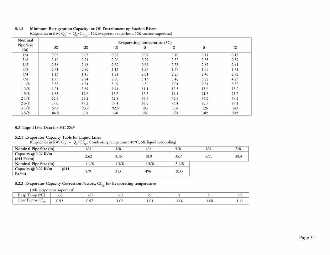
5.1.3 Minimum Refrigeration Capacity for Oil Entrainment up Suction Risers(Capacities in kW, Qe' = Qe/Cfco', 10K evaporator superheat, 10K suction superheat)
NominalPipe Size
(in)
Evaporating Temperature (°C)-30 -20 -10 -5 0 5 10
1/43/81/25/83/47/8
1 1/81 3/81 5/82 1/82 5/83 1/83 5/8
0.05 0.07 0.08 0.09 0.10 0.11 0.130.16 0.21 0.26 0.29 0.32 0.35 0.390.38 0.48 0.60 0.66 0.75 0.82 0.910.71 0.90 1.13 1.27 1.39 1.55 1.711.13 1.45 1.81 2.01 2.25 2.46 2.721.75 2.24 2.80 3.13 3.46 3.82 4.233.55 4.54 5.69 6.36 7.01 7.81 8.526.21 7.89 9.94 11.1 12.3 13.6 15.09.83 12.6 15.7 17.5 19.4 21.5 23.720.5 26.2 32.8 36.5 40.5 45.0 49.237.0 47.2 59.4 66.0 73.4 80.7 89.157.7 73.7 92.5 103 114 126 14086.5 110 138 154 170 189 209
5.2 Liquid Line Data for HC-22a®
5.2.1 Evaporator Capacity Table for Liquid Lines(Capacities in kW, Qe' = Qe/Cfte, Condensing temperature 40°C, 5K liquid subcooling)
Nominal Pipe Size (in) 1/4 3/8 1/2 5/8 3/4 7/8Capacity @ 0.02 K/m(644 Pa/m) 2.62 8.15 18.9 35.7 57.1 88.4
Nominal Pipe Size (in) 1 1/8 1 3/8 1 5/8 2 1/8Capacity @ 0.02 K/m (644Pa/m) 179 313 496 1033
5.2.2 Evaporator Capacity Correction Factors, Cfte for Evaporating temperature
(10K evaporator superheat)Evap Temp (°C) -30 -20 -10 -5 0 5 10Corr Factor Cfte 0.92 0.97 1.02 1.04 1.06 1.08 1.11
Page 32
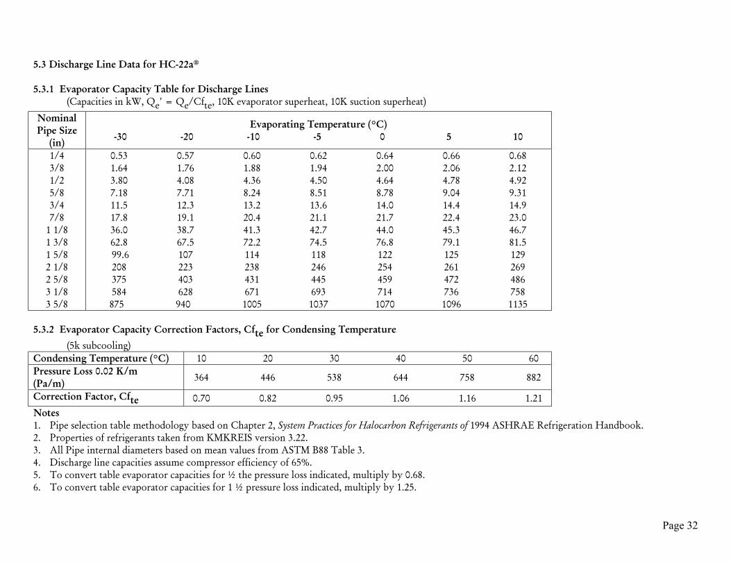
5.3 Discharge Line Data for HC-22a®
5.3.1 Evaporator Capacity Table for Discharge Lines(Capacities in kW, Qe' = Qe/Cfte, 10K evaporator superheat, 10K suction superheat)
NominalPipe Size
(in)
Evaporating Temperature (°C)-30 -20 -10 -5 0 5 10
1/43/81/25/83/47/8
1 1/81 3/81 5/82 1/82 5/83 1/83 5/8
0.53 0.57 0.60 0.62 0.64 0.66 0.681.64 1.76 1.88 1.94 2.00 2.06 2.123.80 4.08 4.36 4.50 4.64 4.78 4.927.18 7.71 8.24 8.51 8.78 9.04 9.3111.5 12.3 13.2 13.6 14.0 14.4 14.917.8 19.1 20.4 21.1 21.7 22.4 23.036.0 38.7 41.3 42.7 44.0 45.3 46.762.8 67.5 72.2 74.5 76.8 79.1 81.599.6 107 114 118 122 125 129208 223 238 246 254 261 269375 403 431 445 459 472 486584 628 671 693 714 736 758875 940 1005 1037 1070 1096 1135
5.3.2 Evaporator Capacity Correction Factors, Cfte for Condensing Temperature
(5k subcooling)Condensing Temperature (°C) 10 20 30 40 50 60Pressure Loss 0.02 K/m(Pa/m) 364 446 538 644 758 882
Correction Factor, Cfte 0.70 0.82 0.95 1.06 1.16 1.21Notes1. Pipe selection table methodology based on Chapter 2, System Practices for Halocarbon Refrigerants of 1994 ASHRAE Refrigeration Handbook.2. Properties of refrigerants taken from KMKREIS version 3.22.3. All Pipe internal diameters based on mean values from ASTM B88 Table 3.4. Discharge line capacities assume compressor efficiency of 65%.5. To convert table evaporator capacities for ½ the pressure loss indicated, multiply by 0.68.6. To convert table evaporator capacities for 1 ½ pressure loss indicated, multiply by 1.25.

Page 33
6 PIPE SELECTION TABLES FOR HC-502a®
6.1 Suction Line Data for HC-502a®
6.1.1 Evaporator Capacity Table for Suction Lines(Capacities in kW, Qe' = Qe/Cfco', 10K evaporator superheat, 10K suction superheat)
Evaporating (Dew/Bubble) Temperature (°C) -30/-36.0 -20/-25.7 -10/-15. -5/-10.2 0/-5.0 5/0.1 10/5.3
NominalPipe Size
(in)
Suction Line Pressure Loss (equivalent to 0.04 K/m) (Pa/m)
276 372 484 548 612 688 7681/43/81/25/83/47/8
1 1/81 3/81 5/82 1/82 5/83 1/83 5/8
0.13 0.19 0.28 0.33 0.39 0.46 0.540.40 0.60 0.87 1.04 1.22 1.44 1.690.93 1.40 2.02 2.41 2.84 3.34 3.911.76 2.64 3.81 4.55 5.36 6.32 7.402.81 4.21 6.08 7.26 8.56 10.1 11.84.35 6.54 9.43 11.3 13.3 15.7 19.38.81 13.2 19.1 22.8 26.9 31.7 37.115.4 23.1 33.4 39.8 46.9 55.3 64.824.4 36.7 52.9 63.2 74.4 87.7 10350.8 76.3 110 132 155 183 21491.9 138 199 238 280 330 387143 215 310 370 437 515 602214 322 464 555 660 771 902
6.1.2 Evaporator Capacity Correction Factors, Cfco' for Condenser Outlet Temperature
Condenser Outlet Temperature (°C) 5.7 16.0 26.3 36.6 46.9 57.3Correction Factor Cfco' 1.34 1.23 1.12 1.00 0.88 0.74
Page 34
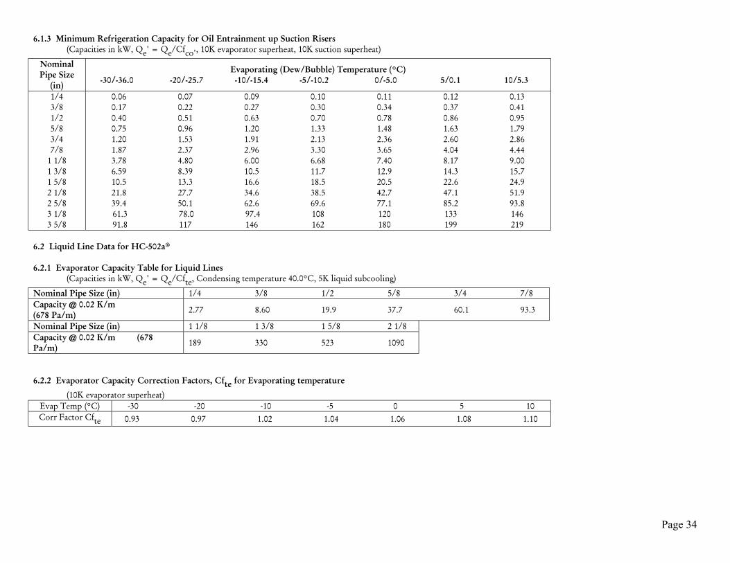
6.1.3 Minimum Refrigeration Capacity for Oil Entrainment up Suction Risers(Capacities in kW, Qe' = Qe/Cfco', 10K evaporator superheat, 10K suction superheat)
NominalPipe Size
(in)
Evaporating (Dew/Bubble) Temperature (°C) -30/-36.0 -20/-25.7 -10/-15.4 -5/-10.2 0/-5.0 5/0.1 10/5.3
1/43/81/25/83/47/8
1 1/81 3/81 5/82 1/82 5/83 1/83 5/8
0.06 0.07 0.09 0.10 0.11 0.12 0.130.17 0.22 0.27 0.30 0.34 0.37 0.410.40 0.51 0.63 0.70 0.78 0.86 0.950.75 0.96 1.20 1.33 1.48 1.63 1.791.20 1.53 1.91 2.13 2.36 2.60 2.861.87 2.37 2.96 3.30 3.65 4.04 4.443.78 4.80 6.00 6.68 7.40 8.17 9.006.59 8.39 10.5 11.7 12.9 14.3 15.710.5 13.3 16.6 18.5 20.5 22.6 24.921.8 27.7 34.6 38.5 42.7 47.1 51.939.4 50.1 62.6 69.6 77.1 85.2 93.861.3 78.0 97.4 108 120 133 14691.8 117 146 162 180 199 219
6.2 Liquid Line Data for HC-502a®
6.2.1 Evaporator Capacity Table for Liquid Lines(Capacities in kW, Qe' = Qe/Cfte, Condensing temperature 40.0°C, 5K liquid subcooling)
Nominal Pipe Size (in) 1/4 3/8 1/2 5/8 3/4 7/8Capacity @ 0.02 K/m(678 Pa/m) 2.77 8.60 19.9 37.7 60.1 93.3
Nominal Pipe Size (in) 1 1/8 1 3/8 1 5/8 2 1/8Capacity @ 0.02 K/m (678Pa/m) 189 330 523 1090
6.2.2 Evaporator Capacity Correction Factors, Cfte for Evaporating temperature
(10K evaporator superheat)Evap Temp (°C) -30 -20 -10 -5 0 5 10Corr Factor Cfte 0.93 0.97 1.02 1.04 1.06 1.08 1.10

Page 35
6.3 Discharge Line Data for HC-502a®
6.3.1 Evaporator Capacity Table for Discharge Lines(Capacities in kW, Qe' = Qe/Cfte, 10K evaporator superheat, 10K suction superheat)
NominalPipe Size
(in)
Evaporating (Dew/Bubble) Temperature (°C) -30/-36.0 -20/-25.7 -10/-15.4 -5/-10.2 0/-5.0 5/0.1 10/5.3
1/43/81/25/83/47/8
1 1/81 3/81 5/82 1/82 5/83 1/83 5/8
0.57 0.62 0.66 0.68 0.70 0.72 0.741.78 1.91 2.04 2.11 2.17 2.24 2.304.13 4.43 4.74 4.89 5.04 5.19 5.337.81 8.38 8.96 9.24 9.53 9.80 10.112.5 13.4 14.3 14.8 15.2 15.7 16.119.3 20.8 22.2 22.9 23.6 24.3 25.039.2 42.0 44.9 46.3 47.8 49.2 50.668.4 73.4 78.4 80.9 93.4 85.8 88.3108 116 124 128 132 136 140226 242 259 267 275 284 292408 438 468 483 498 512 527636 682 729 752 775 798 821952 1022 1092 1126 1161 1195 1229
6.3.2 Evaporator Capacity Correction Factors, Cfte for Condensing Temperature
(5k subcooling)Condensing Temperature (°C) 10 20 30 40 50 60Pressure Loss 0.02 K/m (Pa/m) 384 472 570 678 802 938Correction Factor, Cfte 0.72 0.86 0.99 1.12 1.23 1.30Notes1. Pipe selection table methodology based on Chapter 2, System Practices for Halocarbon Refrigerants of 1994 ASHRAE Refrigeration Handbook.2. Properties of refrigerants taken from KMKREIS version 3.22.3. All Pipe internal diameters based on mean values from ASTM B88 Table 3.4. Discharge line capacities assume compressor efficiency of 65%.5. To convert table evaporator capacities for ½ the pressure loss indicated, multiply by 0.68.6. To convert table evaporator capacities for 1 ½ pressure loss indicated, multiply by 1.25.
Page 36
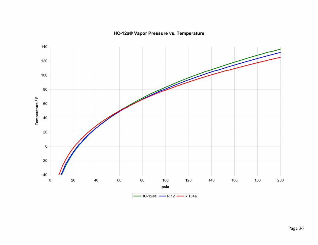
HC-12a® Vapor Pressure vs. Temperature
-40
-20
0
20
40
60
80
100
120
140
0 20 40 60 80 100 120 140 160 180 200
psia
Tem
pera
ture
° F
HC-12a® R 12 R 134a

Page 37
HC-12a®: Bubble Point (Standard)Temperature Pressure (Liquid) Pressure (Vapor) Density
(Liquid) Density (Vapor) Enthalpy(Liquid)
Enthalpy(Vapor) Entropy (Liquid) Entropy (Vapor)
(ºF) (psia) (psia) (lb/ft^3) (lb/ft^3) (Btu/lb) (Btu/lb) (Btu/R-lb) (Btu/R-lb)-40 10.7 10.7 37.5 0.1 46.7 208.5 0.2 0.5-35 12.0 12.0 37.3 0.1 49.3 210.1 0.2 0.5-30 13.5 13.5 37.1 0.2 51.9 211.6 0.2 0.5-25 15.2 15.2 36.9 0.2 54.6 213.2 0.2 0.5-20 17.0 17.0 36.7 0.2 57.2 214.8 0.2 0.5-15 19.0 19.0 36.5 0.2 59.9 216.3 0.2 0.5-10 21.1 21.1 36.3 0.2 62.6 217.9 0.2 0.5-5 23.5 23.5 36.1 0.3 65.3 219.5 0.2 0.50 26.0 26.0 35.9 0.3 68.1 221.0 0.2 0.55 28.7 28.7 35.7 0.3 70.8 222.6 0.2 0.510 31.7 31.7 35.5 0.3 73.6 224.2 0.2 0.515 34.8 34.8 35.3 0.4 76.4 225.8 0.2 0.520 38.2 38.2 35.1 0.4 79.2 227.3 0.2 0.525 41.8 41.8 34.9 0.4 82.0 228.9 0.2 0.530 45.7 45.7 34.7 0.5 84.9 230.5 0.2 0.535 49.9 49.9 34.5 0.5 87.8 232.0 0.2 0.540 54.3 54.3 34.3 0.6 90.7 233.6 0.2 0.545 59.0 59.0 34.0 0.6 93.6 235.2 0.3 0.550 64.0 64.0 33.8 0.7 96.5 236.7 0.3 0.555 69.4 69.4 33.6 0.7 99.5 238.3 0.3 0.560 75.0 75.0 33.4 0.8 102.5 239.8 0.3 0.565 81.0 81.0 33.1 0.8 105.5 241.4 0.3 0.570 87.3 87.3 32.9 0.9 108.5 242.9 0.3 0.575 94.0 94.0 32.6 1.0 111.6 244.5 0.3 0.580 101.0 101.0 32.4 1.0 114.7 246.0 0.3 0.585 108.4 108.4 32.2 1.1 117.8 247.5 0.3 0.590 116.2 116.2 31.9 1.2 120.9 249.0 0.3 0.595 124.4 124.4 31.6 1.3 124.1 250.5 0.3 0.5100 133.0 133.0 31.4 1.3 127.3 252.0 0.3 0.5105 142.1 142.1 31.1 1.4 130.6 253.5 0.3 0.5110 151.5 151.5 30.8 1.5 133.8 254.9 0.3 0.5

Page 38
HC-12a®: Dew Point (Standard)
Temperature Pressure (Liquid) Pressure (Vapor) Density (Liquid) Density (Vapor) Enthalpy(Liquid) Enthalpy (Vapor) Entropy (Liquid) Entropy (Vapor)
(ºF) (psia) (psia) (lb/ft^3) (lb/ft^3) (Btu/lb) (Btu/lb) (Btu/R-lb) (Btu/R-lb)-40 7.0 7.0 35.3 0.1 51.5 222.2 0.2 0.6-35 8.0 8.0 35.2 0.1 54.2 223.7 0.2 0.6-30 9.2 9.2 35.1 0.1 57.0 225.3 0.2 0.6-25 10.4 10.4 34.9 0.1 59.7 226.8 0.2 0.6-20 11.8 11.8 34.8 0.1 62.4 228.3 0.2 0.6-15 13.3 13.3 34.6 0.1 65.2 229.8 0.2 0.6-10 15.0 15.0 34.5 0.2 68.0 231.3 0.2 0.6-5 16.8 16.8 34.3 0.2 70.8 232.9 0.2 0.60 18.8 18.8 34.2 0.2 73.6 234.4 0.2 0.65 21.0 21.0 34.0 0.2 76.4 235.9 0.2 0.610 23.4 23.4 33.9 0.2 79.2 237.4 0.2 0.615 25.9 25.9 33.7 0.3 82.1 239.0 0.2 0.620 28.7 28.7 33.5 0.3 84.9 240.5 0.2 0.625 31.7 31.7 33.4 0.3 87.8 242.0 0.2 0.630 34.9 34.9 33.2 0.4 90.7 243.5 0.3 0.635 38.4 38.4 33.0 0.4 93.6 245.0 0.3 0.640 42.2 42.2 32.9 0.4 96.5 246.5 0.3 0.645 46.2 46.2 32.7 0.5 99.5 248.1 0.3 0.650 50.5 50.5 32.5 0.5 102.4 249.6 0.3 0.655 55.0 55.0 32.3 0.6 105.4 251.1 0.3 0.660 59.9 59.9 32.1 0.6 108.4 252.5 0.3 0.665 65.1 65.1 31.9 0.7 111.4 254.0 0.3 0.670 70.7 70.7 31.7 0.7 114.5 255.5 0.3 0.675 76.5 76.5 31.6 0.8 117.6 257.0 0.3 0.680 82.8 82.8 31.3 0.8 120.6 258.4 0.3 0.685 89.4 89.4 31.1 0.9 123.7 259.9 0.3 0.690 96.4 96.4 30.9 1.0 126.9 261.3 0.3 0.695 103.7 103.7 30.7 1.0 130.0 262.7 0.3 0.6100 111.5 111.5 30.5 1.1 133.2 264.1 0.3 0.6105 119.8 119.8 30.3 1.2 136.4 265.5 0.3 0.6110 128.4 128.4 30.1 1.3 139.7 266.9 0.3 0.6

Page 39
HC-12a®: Bubble Point (Metric)
Temperature Pressure(Liquid)
Pressure(Vapor)
Density(Liquid)
Density(Vapor)
Enthalpy(Liquid)
Enthalpy(Vapor)
Entropy(Liquid)
Entropy(Vapor)
(ºC) (kPa) (kPa) (kg/m^3) (kg/m^3) (kJ/kg) (kJ/kg) (kJ/K-kg) (kJ/K-kg)-40 73.40 73.40 600.80 1.96 108.50 484.70 0.64 2.23-35 91.20 91.20 595.30 2.40 119.50 491.20 0.69 2.23-30 112.20 112.20 589.70 2.91 130.60 497.70 0.73 2.22-25 136.70 136.70 584.00 3.49 141.80 504.30 0.78 2.22-20 165.20 165.20 578.20 4.17 153.10 510.90 0.82 2.21-15 198.00 198.00 572.40 4.94 164.60 517.50 0.87 2.21-10 235.60 235.60 566.50 5.81 176.30 524.00 0.91 2.21-5 278.20 278.20 560.40 6.79 188.10 530.60 0.96 2.210 326.50 326.50 554.20 7.90 200.00 537.20 1.00 2.215 380.80 380.80 548.00 9.14 212.10 543.70 1.04 2.2110 441.50 441.50 541.50 10.53 224.40 550.30 1.09 2.2115 509.20 509.20 535.00 12.08 236.80 556.80 1.13 2.2220 584.10 584.10 528.20 13.80 249.40 563.20 1.17 2.2225 666.90 666.90 521.30 15.71 262.30 569.70 1.22 2.2230 758.00 758.00 514.20 17.83 275.30 576.00 1.26 2.2335 857.80 857.80 506.80 20.18 288.50 582.30 1.30 2.2340 966.80 966.80 499.20 22.79 302.00 588.50 1.34 2.2445 1085.50 1085.50 491.40 25.67 315.70 594.60 1.39 2.2450 1214.50 1214.50 483.20 28.88 329.70 600.50 1.43 2.2455 1354.10 1354.10 474.70 32.44 343.90 606.40 1.47 2.2560 1505.10 1505.10 465.80 36.40 358.50 612.00 1.52 2.2565 1667.80 1667.80 456.50 40.83 373.40 617.40 1.56 2.2670 1842.80 1842.80 446.60 45.80 388.60 622.50 1.60 2.2675 2030.80 2030.80 436.20 51.41 404.30 627.30 1.65 2.2780 2232.30 2232.30 425.00 57.79 420.40 631.60 1.69 2.27

Page 40
HC-12a®: Dew Point (Metric)
Temperature Pressure(Liquid)
Pressure(Vapor)
Density(Liquid)
Density(Vapor)
Enthalpy(Liquid)
Enthalpy(Vapor)
Entropy(Liquid)
Entropy(Vapor)
(ºC) (kPa) (kPa) (kg/m^3) (kg/m^3) (kJ/kg) (kJ/kg) (kJ/K-kg) (kJ/K-kg)-40 48.30 48.30 566.00 1.28 119.80 516.50 0.68 2.43-35 61.50 61.50 562.00 1.61 131.10 522.90 0.73 2.41-30 77.30 77.30 557.80 1.99 142.60 529.20 0.78 2.40-25 96.20 96.20 553.60 2.44 154.10 535.60 0.83 2.39-20 118.50 118.50 549.20 2.96 165.80 542.00 0.87 2.39-15 144.70 144.70 544.80 3.57 177.50 548.40 0.92 2.38-10 175.10 175.10 540.20 4.26 189.40 554.70 0.97 2.37-5 210.10 210.10 535.50 5.06 201.40 561.10 1.01 2.370 250.30 250.30 530.60 5.97 213.50 567.50 1.06 2.375 296.10 296.10 525.60 7.00 225.70 573.80 1.10 2.3610 347.90 347.90 520.50 8.17 238.10 580.10 1.15 2.3615 406.20 406.20 515.20 9.48 250.60 586.30 1.19 2.3620 471.60 471.60 509.70 10.94 263.30 592.50 1.23 2.3625 544.50 544.50 504.00 12.59 276.10 598.70 1.28 2.3630 625.60 625.60 498.20 14.43 289.10 604.70 1.32 2.3635 715.20 715.20 492.10 16.48 302.30 610.70 1.36 2.3640 814.10 814.10 485.70 18.77 315.60 616.50 1.40 2.3645 922.80 922.80 479.10 21.33 329.20 622.20 1.45 2.3650 1041.90 1041.90 472.20 24.18 342.90 627.80 1.49 2.3655 1172.00 1172.00 465.00 27.37 356.90 633.20 1.53 2.3660 1313.90 1313.90 457.30 30.94 371.10 638.30 1.57 2.3765 1468.30 1468.30 449.30 34.95 385.60 643.20 1.61 2.3770 1635.90 1635.90 440.70 39.47 400.40 647.70 1.65 2.3775 1817.70 1817.70 431.60 44.61 415.50 651.90 1.70 2.3780 2014.60 2014.60 421.80 50.47 431.00 655.50 1.74 2.36

Page 41
HC-22a® Vapor Pressure vs. Temperature
-60
-40
-20
0
20
40
60
80
100
120
140
160
0 40 80 120 160 200 240 280 320 360 400
psia
Tem
pera
ture
° F
HC-22a® R 22

Page 42
HC-22a®: Bubble Point (Standard)
Temperature Pressure(Liquid)
Pressure(Vapor)
Density(Liquid)
Density(Vapor)
Enthalpy(Liquid)
Enthalpy(Vapor)
Entropy(Liquid)
Entropy(Vapor)
(ºF) (psia) (psia) (lb/ft^3) (lb/ft^3) (Btu/lb) (Btu/lb) (Btu/R-lb) (Btu/R-lb)-40 18.2 18.2 36.1 0.2 45.3 220.3 0.2 0.6-35 20.4 20.4 35.9 0.2 48.0 222.0 0.2 0.6-30 22.8 22.8 35.7 0.2 50.7 223.6 0.2 0.6-25 25.4 25.4 35.4 0.3 53.5 225.2 0.2 0.6-20 28.2 28.2 35.2 0.3 56.3 226.9 0.2 0.6-15 31.3 31.3 35.0 0.3 59.1 228.5 0.2 0.6-10 34.6 34.6 34.8 0.3 61.9 230.0 0.2 0.6-5 38.2 38.2 34.6 0.4 64.7 231.6 0.2 0.60 42.1 42.1 34.4 0.4 67.5 233.2 0.2 0.65 46.2 46.2 34.2 0.4 70.4 234.7 0.2 0.610 50.7 50.7 33.9 0.5 73.3 236.3 0.2 0.615 55.4 55.4 33.7 0.5 76.2 237.8 0.2 0.620 60.5 60.5 33.5 0.6 79.2 239.3 0.2 0.625 65.9 65.9 33.3 0.6 82.1 240.8 0.2 0.630 71.7 71.7 33.0 0.7 85.1 242.2 0.2 0.635 77.9 77.9 32.8 0.7 88.2 243.7 0.2 0.640 84.4 84.4 32.5 0.8 91.2 245.1 0.3 0.645 91.4 91.4 32.3 0.8 94.3 246.6 0.3 0.650 98.7 98.7 32.1 0.9 97.4 248.0 0.3 0.655 106.5 106.5 31.8 1.0 100.5 249.3 0.3 0.660 114.8 114.8 31.5 1.1 103.7 250.7 0.3 0.665 123.4 123.4 31.3 1.1 106.8 252.0 0.3 0.670 132.6 132.6 31.0 1.2 110.1 253.3 0.3 0.675 142.3 142.3 30.7 1.3 113.3 254.6 0.3 0.680 152.4 152.4 30.5 1.4 116.6 255.9 0.3 0.685 163.1 163.1 30.2 1.5 120.0 257.1 0.3 0.690 174.4 174.4 29.9 1.6 123.3 258.3 0.3 0.695 186.1 186.1 29.6 1.7 126.7 259.5 0.3 0.6100 198.5 198.5 29.3 1.9 130.2 260.6 0.3 0.6105 211.4 211.4 29.0 2.0 133.7 261.7 0.3 0.6110 225.0 225.0 28.7 2.1 137.2 262.8 0.3 0.6
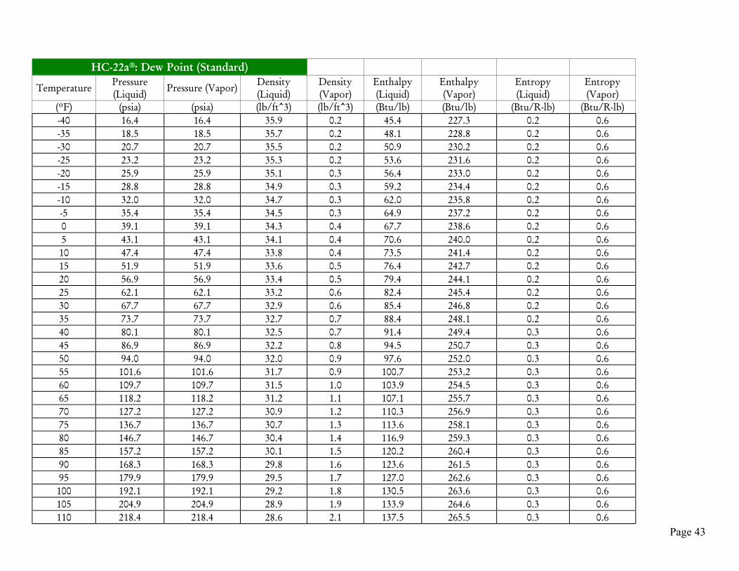
Page 43
HC-22a®: Dew Point (Standard)
Temperature Pressure(Liquid) Pressure (Vapor) Density
(Liquid)Density(Vapor)
Enthalpy(Liquid)
Enthalpy(Vapor)
Entropy(Liquid)
Entropy(Vapor)
(ºF) (psia) (psia) (lb/ft^3) (lb/ft^3) (Btu/lb) (Btu/lb) (Btu/R-lb) (Btu/R-lb)-40 16.4 16.4 35.9 0.2 45.4 227.3 0.2 0.6-35 18.5 18.5 35.7 0.2 48.1 228.8 0.2 0.6-30 20.7 20.7 35.5 0.2 50.9 230.2 0.2 0.6-25 23.2 23.2 35.3 0.2 53.6 231.6 0.2 0.6-20 25.9 25.9 35.1 0.3 56.4 233.0 0.2 0.6-15 28.8 28.8 34.9 0.3 59.2 234.4 0.2 0.6-10 32.0 32.0 34.7 0.3 62.0 235.8 0.2 0.6-5 35.4 35.4 34.5 0.3 64.9 237.2 0.2 0.60 39.1 39.1 34.3 0.4 67.7 238.6 0.2 0.65 43.1 43.1 34.1 0.4 70.6 240.0 0.2 0.610 47.4 47.4 33.8 0.4 73.5 241.4 0.2 0.615 51.9 51.9 33.6 0.5 76.4 242.7 0.2 0.620 56.9 56.9 33.4 0.5 79.4 244.1 0.2 0.625 62.1 62.1 33.2 0.6 82.4 245.4 0.2 0.630 67.7 67.7 32.9 0.6 85.4 246.8 0.2 0.635 73.7 73.7 32.7 0.7 88.4 248.1 0.2 0.640 80.1 80.1 32.5 0.7 91.4 249.4 0.3 0.645 86.9 86.9 32.2 0.8 94.5 250.7 0.3 0.650 94.0 94.0 32.0 0.9 97.6 252.0 0.3 0.655 101.6 101.6 31.7 0.9 100.7 253.2 0.3 0.660 109.7 109.7 31.5 1.0 103.9 254.5 0.3 0.665 118.2 118.2 31.2 1.1 107.1 255.7 0.3 0.670 127.2 127.2 30.9 1.2 110.3 256.9 0.3 0.675 136.7 136.7 30.7 1.3 113.6 258.1 0.3 0.680 146.7 146.7 30.4 1.4 116.9 259.3 0.3 0.685 157.2 157.2 30.1 1.5 120.2 260.4 0.3 0.690 168.3 168.3 29.8 1.6 123.6 261.5 0.3 0.695 179.9 179.9 29.5 1.7 127.0 262.6 0.3 0.6100 192.1 192.1 29.2 1.8 130.5 263.6 0.3 0.6105 204.9 204.9 28.9 1.9 133.9 264.6 0.3 0.6110 218.4 218.4 28.6 2.1 137.5 265.5 0.3 0.6

Page 44
HC-22a®: Bubble Point (Metric)
Temperature Pressure(Liquid)
Pressure(Vapor)
Density(Liquid)
Density(Vapor)
Enthalpy(Liquid)
Enthalpy(Vapor)
Entropy(Liquid)
Entropy(Vapor)
(ºC) (kPa) (kPa) (kg/m3) (kg/m3) (kJ/kg) (kJ/kg) (kJ/K-kg) (kJ/K-kg)-40 126.0 125.5 578.0 3.0 105.2 512.1 0.6 2.5-35 154.0 153.8 572.0 3.6 116.6 519.0 0.7 2.4-30 187.0 186.7 566.0 4.3 128.2 525.8 0.7 2.4-25 225.0 224.8 560.0 5.1 139.9 532.5 0.8 2.4-20 269.0 268.6 553.0 6.0 151.7 539.1 0.8 2.4-15 319.0 318.6 547.0 7.1 163.7 545.6 0.9 2.4-10 375.0 375.3 541.0 8.3 175.8 552.0 0.9 2.4-5 439.0 439.3 534.0 9.6 188.2 558.3 1.0 2.40 511.0 511.2 527.0 11.1 200.7 564.4 1.0 2.45 591.0 591.5 520.0 12.8 213.4 570.5 1.1 2.410 681.0 680.8 513.0 14.7 226.3 576.4 1.1 2.415 780.0 779.6 506.0 16.8 239.5 582.1 1.2 2.420 889.0 888.7 498.0 19.2 252.8 587.7 1.2 2.425 1009.0 1009.0 491.0 21.8 266.5 593.1 1.2 2.430 1140.0 1140.0 482.0 24.7 280.4 598.2 1.3 2.435 1283.0 1283.0 474.0 28.0 294.6 603.2 1.3 2.440 1440.0 1440.0 465.0 31.7 309.1 607.8 1.4 2.445 1609.0 1609.0 456.0 35.8 324.0 612.1 1.4 2.450 1793.0 1793.0 446.0 40.4 339.2 616.1 1.5 2.355 1992.0 1992.0 436.0 45.7 354.9 619.6 1.5 2.360 2207.0 2207.0 425.0 51.7 371.1 622.5 1.6 2.365 2439.0 2439.0 413.0 58.6 387.8 624.8 1.6 2.370 2688.0 2688.0 400.0 66.7 405.3 626.2 1.7 2.375 2956.0 2956.0 385.0 76.3 423.6 626.5 1.7 2.380 3243.0 3243.0 369.0 88.0 443.1 625.2 1.8 2.385 3552.0 3552.0 349.0 103.1 464.5 621.5 1.8 2.390 3884.0 3884.0 323.0 124.6 489.4 613.1 1.9 2.295 4429.0 4429.0 308.0 308.0 509.0 509.0 1.9 1.9
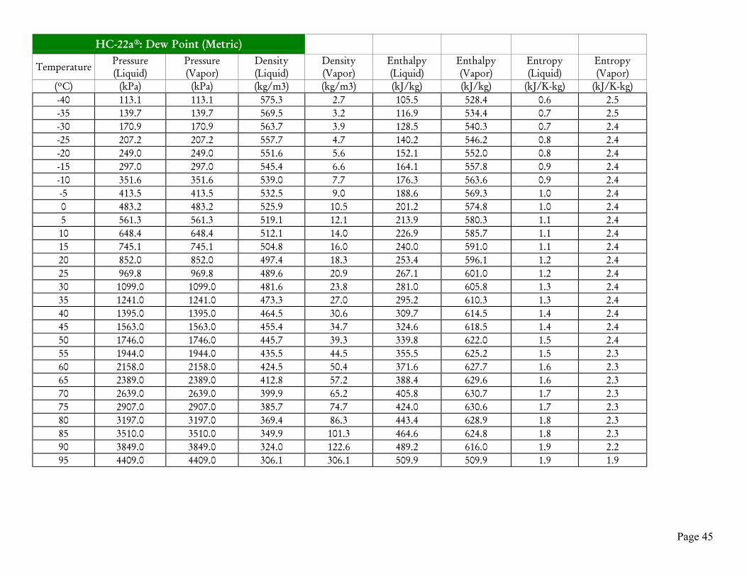
Page 45
HC-22a®: Dew Point (Metric)
Temperature Pressure(Liquid)
Pressure(Vapor)
Density(Liquid)
Density(Vapor)
Enthalpy(Liquid)
Enthalpy(Vapor)
Entropy(Liquid)
Entropy(Vapor)
(ºC) (kPa) (kPa) (kg/m3) (kg/m3) (kJ/kg) (kJ/kg) (kJ/K-kg) (kJ/K-kg)-40 113.1 113.1 575.3 2.7 105.5 528.4 0.6 2.5-35 139.7 139.7 569.5 3.2 116.9 534.4 0.7 2.5-30 170.9 170.9 563.7 3.9 128.5 540.3 0.7 2.4-25 207.2 207.2 557.7 4.7 140.2 546.2 0.8 2.4-20 249.0 249.0 551.6 5.6 152.1 552.0 0.8 2.4-15 297.0 297.0 545.4 6.6 164.1 557.8 0.9 2.4-10 351.6 351.6 539.0 7.7 176.3 563.6 0.9 2.4-5 413.5 413.5 532.5 9.0 188.6 569.3 1.0 2.40 483.2 483.2 525.9 10.5 201.2 574.8 1.0 2.45 561.3 561.3 519.1 12.1 213.9 580.3 1.1 2.410 648.4 648.4 512.1 14.0 226.9 585.7 1.1 2.415 745.1 745.1 504.8 16.0 240.0 591.0 1.1 2.420 852.0 852.0 497.4 18.3 253.4 596.1 1.2 2.425 969.8 969.8 489.6 20.9 267.1 601.0 1.2 2.430 1099.0 1099.0 481.6 23.8 281.0 605.8 1.3 2.435 1241.0 1241.0 473.3 27.0 295.2 610.3 1.3 2.440 1395.0 1395.0 464.5 30.6 309.7 614.5 1.4 2.445 1563.0 1563.0 455.4 34.7 324.6 618.5 1.4 2.450 1746.0 1746.0 445.7 39.3 339.8 622.0 1.5 2.455 1944.0 1944.0 435.5 44.5 355.5 625.2 1.5 2.360 2158.0 2158.0 424.5 50.4 371.6 627.7 1.6 2.365 2389.0 2389.0 412.8 57.2 388.4 629.6 1.6 2.370 2639.0 2639.0 399.9 65.2 405.8 630.7 1.7 2.375 2907.0 2907.0 385.7 74.7 424.0 630.6 1.7 2.380 3197.0 3197.0 369.4 86.3 443.4 628.9 1.8 2.385 3510.0 3510.0 349.9 101.3 464.6 624.8 1.8 2.390 3849.0 3849.0 324.0 122.6 489.2 616.0 1.9 2.295 4409.0 4409.0 306.1 306.1 509.9 509.9 1.9 1.9

Page 46
HC-502a® Vapor Pressure vs. Temperature
-60
-40
-20
0
20
40
60
80
100
120
140
160
0 40 80 120 160 200 240 280 320 360 400
psia
Tem
pera
ture
° F
HC-502a® R 502 R 22

Page 47
HC-502a®: Bubble Point (Standard)
Temperature Pressure(Liquid)
Pressure(Vapor)
Density(Liquid)
Density(Vapor)
Enthalpy(Liquid) Enthalpy (Vapor) Entropy
(Liquid) Entropy (Vapor)
(ºF) (psia) (psia) (lb/ft^3) (lb/ft^3) (Btu/lb) (Btu/lb) (Btu/R-lb) (Btu/R-lb)-40 22.8 22.8 35.9 0.2 45.7 210.3 0.2 0.6-35 25.4 25.4 35.7 0.3 48.4 212.1 0.2 0.6-30 28.2 28.2 35.5 0.3 51.2 214.0 0.2 0.6-25 31.2 31.2 35.2 0.3 53.9 215.8 0.2 0.6-20 34.5 34.5 35.0 0.3 56.7 217.6 0.2 0.6-15 38.0 38.0 34.8 0.4 59.5 219.4 0.2 0.6-10 41.8 41.8 34.6 0.4 62.4 221.2 0.2 0.6-5 45.8 45.8 34.4 0.4 65.2 223.0 0.2 0.60 50.2 50.2 34.2 0.5 68.1 224.7 0.2 0.65 54.9 54.9 33.9 0.5 71.0 226.4 0.2 0.610 59.9 59.9 33.7 0.6 73.9 228.1 0.2 0.615 65.2 65.2 33.5 0.6 76.8 229.8 0.2 0.620 70.9 70.9 33.3 0.7 79.8 231.5 0.2 0.625 76.9 76.9 33.0 0.7 82.8 233.2 0.2 0.630 83.3 83.3 32.8 0.8 85.8 234.8 0.2 0.635 90.1 90.1 32.6 0.8 88.8 236.4 0.3 0.640 97.3 97.3 32.3 0.9 91.9 238.0 0.3 0.645 104.9 104.9 32.1 1.0 95.0 239.6 0.3 0.650 113.0 113.0 31.8 1.0 98.1 241.1 0.3 0.655 121.5 121.5 31.6 1.1 101.3 242.7 0.3 0.660 130.4 130.4 31.3 1.2 104.4 244.2 0.3 0.665 139.9 139.9 31.0 1.3 107.7 245.7 0.3 0.670 149.8 149.8 30.8 1.4 110.9 247.1 0.3 0.675 160.3 160.3 30.5 1.5 114.2 248.5 0.3 0.680 171.2 171.2 30.2 1.6 117.5 249.9 0.3 0.685 182.7 182.7 29.9 1.7 120.9 251.3 0.3 0.690 194.8 194.8 29.6 1.8 124.3 252.6 0.3 0.695 207.4 207.4 29.3 1.9 127.7 253.9 0.3 0.6100 220.6 220.6 29.0 2.1 131.2 255.2 0.3 0.6105 234.4 234.4 28.7 2.2 134.8 256.4 0.3 0.6110 248.9 248.9 28.3 2.4 138.4 257.5 0.3 0.6

Page 48
HC-502a®: Dew Point (Standard)
Temperature Pressure(Liquid)
Pressure(Vapor)
Density(Liquid)
Density(Vapor)
Enthalpy(Liquid) Enthalpy (Vapor) Entropy
(Liquid) Entropy (Vapor)
(ºF) (psia) (psia) (lb/ft^3) (lb/ft^3) (Btu/lb) (Btu/lb) (Btu/R-lb) (Btu/R-lb)-40 17.1 17.1 35.4 0.2 46.0 227.7 0.2 0.6-35 19.3 19.3 35.2 0.2 48.8 229.1 0.2 0.6-30 21.7 21.7 35.0 0.2 51.6 230.6 0.2 0.6-25 24.2 24.2 34.8 0.2 54.4 232.0 0.2 0.6-20 27.0 27.0 34.6 0.3 57.2 233.4 0.2 0.6-15 30.1 30.1 34.4 0.3 60.0 234.8 0.2 0.6-10 33.4 33.4 34.2 0.3 62.9 236.2 0.2 0.6-5 36.9 36.9 34.0 0.4 65.7 237.6 0.2 0.60 40.8 40.8 33.8 0.4 68.6 239.0 0.2 0.65 44.9 44.9 33.6 0.4 71.6 240.3 0.2 0.610 49.4 49.4 33.4 0.5 74.5 241.7 0.2 0.615 54.2 54.2 33.2 0.5 77.5 243.1 0.2 0.620 59.3 59.3 33.0 0.6 80.4 244.4 0.2 0.625 64.8 64.8 32.7 0.6 83.4 245.8 0.2 0.630 70.7 70.7 32.5 0.7 86.5 247.1 0.2 0.635 76.9 76.9 32.3 0.7 89.5 248.4 0.3 0.640 83.5 83.5 32.0 0.8 92.6 249.7 0.3 0.645 90.6 90.6 31.8 0.8 95.7 251.0 0.3 0.650 98.1 98.1 31.6 0.9 98.9 252.2 0.3 0.655 106.0 106.0 31.3 1.0 102.0 253.5 0.3 0.660 114.4 114.4 31.1 1.0 105.2 254.7 0.3 0.665 123.3 123.3 30.8 1.1 108.5 255.9 0.3 0.670 132.7 132.7 30.6 1.2 111.7 257.1 0.3 0.675 142.6 142.6 30.3 1.3 115.0 258.3 0.3 0.680 153.0 153.0 30.0 1.4 118.4 259.4 0.3 0.685 164.0 164.0 29.7 1.5 121.7 260.5 0.3 0.690 175.6 175.6 29.5 1.6 125.1 261.6 0.3 0.695 187.8 187.8 29.2 1.7 128.6 262.6 0.3 0.6100 200.5 200.5 28.9 1.9 132.1 263.6 0.3 0.6105 213.9 213.9 28.6 2.0 135.6 264.6 0.3 0.6110 227.9 227.9 28.2 2.1 139.2 265.5 0.3 0.6

Page 49
HC-502a®: Bubble Point (Metric)
Temperature Pressure(Liquid)
Pressure(Vapor)
Density(Liquid)
Density(Vapor)
Enthalpy(Liquid)
Enthalpy(Vapor)
Entropy(Liquid)
Entropy(Vapor)
(ºC) (kPa) (kPa) (kg/m3) (kg/m3) (kJ/kg) (kJ/kg) (kJ/K-kg) (kJ/K-kg)-40 157.3 157.3 574.5 3.666 106.1 488.8 0.6722 2.404-35 190.3 190.3 568.6 4.373 117.6 496.5 0.7206 2.397-30 228.4 228.4 562.5 5.18 129.2 504.2 0.7686 2.391-25 272.1 272.1 556.4 6.099 141 511.7 0.8161 2.385-20 321.9 321.9 550.1 7.139 152.9 519.1 0.8633 2.38-15 378.3 378.3 543.7 8.312 164.9 526.3 0.9101 2.376-10 441.9 441.9 537.2 9.631 177.2 533.5 0.9566 2.372-5 513.2 513.2 530.5 11.11 189.6 540.4 1.003 2.3690 592.8 592.8 523.7 12.76 202.2 547.3 1.049 2.3665 681.2 681.2 516.7 14.61 215 554 1.095 2.36410 779 779 509.4 16.66 228 560.5 1.14 2.36215 886.8 886.8 502 18.95 241.3 566.9 1.186 2.3620 1005 1005 494.3 21.5 254.8 573.1 1.232 2.35825 1135 1135 486.3 24.33 268.6 579 1.277 2.35630 1276 1276 478 27.49 282.6 584.7 1.323 2.35535 1430 1430 469.3 31.01 296.9 590.2 1.369 2.35340 1597 1597 460.2 34.95 311.6 595.4 1.415 2.35145 1778 1778 450.7 39.36 326.7 600.2 1.461 2.34950 1973 1973 440.7 44.34 342.1 604.6 1.508 2.34655 2183 2183 430 49.97 358 608.5 1.556 2.34260 2410 2410 418.5 56.41 374.5 611.8 1.604 2.33765 2653 2653 406.1 63.85 391.5 614.5 1.653 2.3370 2914 2914 392.5 72.56 409.4 616.2 1.703 2.32275 3194 3194 377.2 83 428.2 616.6 1.756 2.31180 3493 3493 359.4 95.96 448.5 615.2 1.811 2.29585 3812 3812 337.4 113.1 471.1 610.9 1.872 2.27290 4150 4150 305.4 139.8 499.1 600 1.947 2.231

Page 50
HC-502a®: Dew Point (Metric)
Temperature Pressure(Liquid)
Pressure(Vapor)
Density(Liquid)
Density(Vapor)
Enthalpy(Liquid)
Enthalpy(Vapor)
Entropy(Liquid)
Entropy(Vapor)
(ºC) (kPa) (kPa) (kg/m3) (kg/m3) (kJ/kg) (kJ/kg) (kJ/K-kg) (kJ/K-kg)-40 118.1 118.1 567.6 2.743 107 529.3 0.6488 2.501-35 145.9 145.9 562 3.339 118.6 535.3 0.6983 2.488-30 178.4 178.4 556.2 4.029 130.3 541.2 0.7473 2.475-25 216.2 216.2 550.3 4.825 142.2 547 0.7958 2.464-20 259.9 259.9 544.4 5.736 154.2 552.9 0.844 2.455-15 309.9 309.9 538.3 6.775 166.3 558.7 0.8917 2.446-10 366.9 366.9 532.1 7.953 178.7 564.4 0.9392 2.438-5 431.4 431.4 525.7 9.287 191.2 570 0.9863 2.4310 504.1 504.1 519.1 10.79 203.8 575.6 1.033 2.4255 585.5 585.5 512.4 12.48 216.7 581 1.08 2.41910 676.3 676.3 505.5 14.37 229.8 586.3 1.127 2.41415 777.1 777.1 498.4 16.5 243.1 591.5 1.173 2.40920 888.7 888.7 491 18.87 256.7 596.6 1.219 2.40525 1012 1012 483.4 21.53 270.5 601.4 1.266 2.40130 1147 1147 475.4 24.51 284.5 606.1 1.312 2.39635 1294 1294 467.1 27.84 298.9 610.5 1.359 2.39240 1456 1456 458.4 31.58 313.6 614.6 1.406 2.38845 1632 1632 449.3 35.8 328.6 618.4 1.453 2.38450 1823 1823 439.7 40.57 344 621.8 1.5 2.37855 2030 2030 429.4 45.99 359.8 624.7 1.548 2.37360 2255 2255 418.4 52.2 376.2 627 1.597 2.36665 2498 2498 406.5 59.39 393.1 628.6 1.646 2.35770 2761 2761 393.4 67.85 410.7 629.2 1.697 2.34775 3045 3045 378.8 78 429.3 628.5 1.75 2.33480 3352 3352 361.7 90.61 449.2 626.1 1.805 2.31685 3686 3686 340.7 107.3 471.2 620.5 1.866 2.29190 4052 4052 310.6 132.9 497.9 608.5 1.939 2.25


