134 HC/ATEX Technical characteristics HC-25...63 HC-71...100 HC/ATEX HC/ATEX-25-2T/H 2730 0.74 0.43 0.12 2200 64 HC/ATEX-25-4T/H 1400 1.28 0.74 0.12 1300 51 HC/ATEX-31-2T/H 2760 1.21 0.70 0.18 3650 72 HC/ATEX-31-4T/H 1400 1.28 0.74 0.12 2400 54 HC/ATEX-31-4T/L 1320 0.65 0.38 0.09 1800 52 HC/ATEX-35-2T/H 2770 2.08 1.20 0.37 6050 76 HC/ATEX-35-4T/H 1400 1.28 0.74 0.12 3550 58 HC/ATEX-35-4T/L 1400 1.28 0.74 0.12 2600 56 HC/ATEX-40-4T/H 1370 2.08 1.20 0.25 5200 63 HC/ATEX-40-4T/L 1400 1.28 0.74 0.12 4050 59 HC/ATEX-40-6T/H 910 2.42 1.40 0.25 3700 55 HC/ATEX-45-4T/H 1370 2.60 1.50 0.37 7300 66 HC/ATEX-45-4T/L 1370 2.08 1.20 0.25 5600 63 HC/ATEX-45-6T/H 910 2.42 1.40 0.25 5150 57 HC/ATEX-50-4T/H 1410 2.94 1.70 0.55 10200 69 HC/ATEX-50-4T/L 1370 2.08 1.20 0.25 7400 66 Model Speed Maximum current admissible (A) Installed power Maximum airflow Sound pressure level (r/min) 230V 400V 690V (kW) (m 3 /h) dB(A) Ex “e” marked: II 2G Ex e Ex “d” marked: II 2G Ex d Ex tc marked: II 3D Ex tc Ex tb marked: II 2D Ex tb Notified authority: L.O.M Identification No: LOM3ATEX0157 Wall-mounted axial fans with ATEX certification and possible Ex e, Ex d, Ex tc and Ex tb markings Wall-mounted axial fans with ATEX certification, with CEE ExII2G Ex e explosion-proof and CEE ExII2G Ex d, Ex tc, or Ex tb flame-resistant motor to work in explosive atmospheres of gas or dust. Fan: • Impeller made from cast aluminium • Airflow direction from motor to impeller • Stuffing-box spark-proof included • Protection guard against contacts, in accordance with standard UNE-EN ISO 12499:2010 included in models 25 to 63, other models as accessory. • Support frame in sheet steel with aluminium strip in the impeller area in accordance with Standard EN-14986:2007 Motor: • Class F motors with ball bearings and ATEX certification, Ex e explosion-proof and Ex d, Ex tc, or Ex tb flame-resistant • Three phase, 50Hz, 230/400V motors up to and including 4kW. 400/690V over 4kW • Fan working temperature: -20ºC + 40ºC Finish: • Rust retardant finish with ATEX paint, containing no ferrous components, in polyester resin polymerised at 190ºC, after phosphate free pre-treatment On request: • Built-in motors with PTC • Special windings for different electrical supplies and frequencies • ATEX construction for different categories • Fans with two-speed motor. • Ex d flame-resistant single-phase motors Order code HC/ATEX 25 2T/H Ex-e I F Impeller diameter in cm. Wall-mounted axial fans, with ATEX motor Marked: II 2G c II 2D c II 3D c Number of motor pole 2=2900 r/min. 50 Hz 4=1400 r/min. 50 Hz 6=900 r/min. 50 Hz T=Three-phase M=Single-phase H=High airflow L=Low airflow Air circulation I=Impeller Motor->Impeller A=Airflow-in Impeller->Motor Execution of the fan Execution standard F=Motor impeller unit guard G=Motor impeller unit Ex-e: marked: II 2G Ex e IIB T3 Ex “d” marked: II 2G Ex d IIB T5 Ex tc marked: II 3D Ex tc Ex tb marked: II 2D Ex tb
Ex “e” marked: II 2G Ex eEx “d” marked: II 2G Ex dEx tc marked: II 3D Ex tcEx tb marked: II 2D Ex tbNotified authority: L.O.MIdentification No: LOM3ATEX0157
Wall-mounted axial fans with ATEX certification and possible Ex e, Ex d, Ex tc and Ex tb markings
Wall-mounted axial fans with ATEX certification, with CEE ExII2G Ex e explosion-proof and CEE ExII2G Ex d, Ex tc, or Ex tb flame-resistant motor to work in explosive atmospheres of gas or dust.
Fan:• Impeller made from cast aluminium• Airflow direction from motor to impeller• Stuffing-box spark-proof included• Protection guard against contacts, in accordance
with standard UNE-EN ISO 12499:2010 included in models 25 to 63, other models as accessory.
• Support frame in sheet steel with aluminium strip in the impeller area in accordance with Standard EN-14986:2007
Motor:• Class F motors with ball bearings and ATEX
certification, Ex e explosion-proof and Ex d, Ex tc, or Ex tb flame-resistant
• Three phase, 50Hz, 230/400V motors up to and including 4kW. 400/690V over 4kW
• Fan working temperature: -20ºC + 40ºC
Finish: • Rust retardant finish with ATEX paint,
containing no ferrous components, in polyester resin polymerised at 190ºC, after phosphate free pre-treatment
On request:• Built-in motors with PTC• Special windings for different
electrical supplies and frequencies• ATEX construction for different categories• Fans with two-speed motor.• Ex d flame-resistant single-phase motors
Order code
HC/ATEX 25 2T/H Ex-e I F
Impeller diameter in cm.
Wall-mounted axial fans, with ATEX motor
Marked: II 2G c II 2D c II 3D c
Number of motor pole2=2900 r/min. 50 Hz4=1400 r/min. 50 Hz6=900 r/min. 50 Hz
The specified values are determined according to free field measurements of pressure and sound levels in dB(A) at an equivalent distance of twice the fan’s span plus the impeller’s diameter, with a minimum of 1.5 m.
Acoustic features
Sound power Lw(A) spectrum in dB(A) via frequency band in Hz.
Characteristic curvesQ = Airflow in m3/h, m3/s and cfm. Pe= Static pressure in mmH2O, Pa and inwg.
137
HC/ATEX HC/ATEX
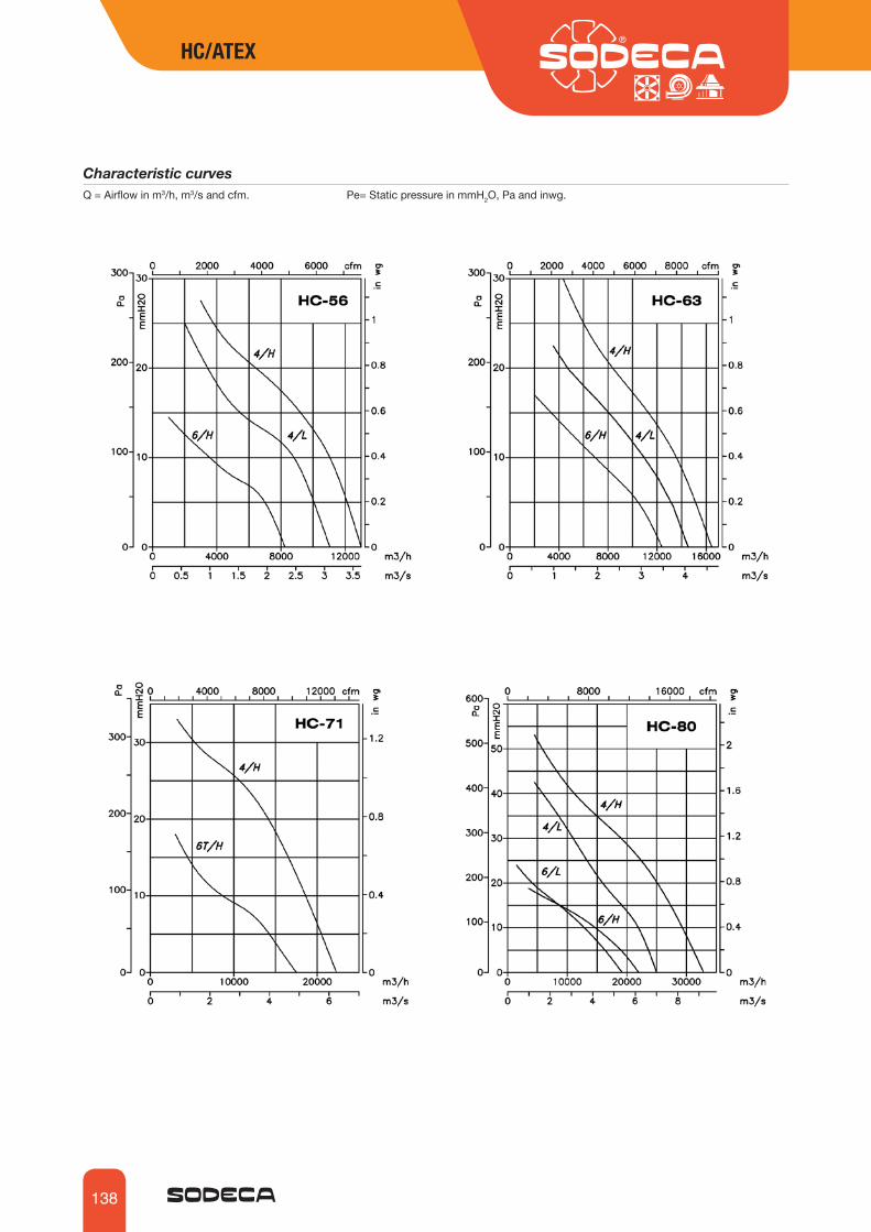
Characteristic curvesQ = Airflow in m3/h, m3/s and cfm. Pe= Static pressure in mmH2O, Pa and inwg.
138
HC/ATEX HC/ATEX
Characteristic curvesQ = Airflow in m3/h, m3/s and cfm. Pe= Static pressure in mmH2O, Pa and inwg.
139
HC/ATEX HC/ATEX
INT AR CUADROS P RI SR INT-ATEXVSD3/A-RFTVSD1/A-RFM
AccessoriesSee accessories section.
Characteristic curvesQ = Airflow in m3/h, m3/s and cfm. Pe= Static pressure in mmH2O, Pa and inwg.


![Coriolis Mass Flowmeter - rockwin.com · ATEX approval Ex II (1) G ... ATEX approval Ex II 2(1) G Ex db eb [ia Ga] IIC T5 ATEX approval Ex II 2(1) G Ex db [ia Ga] IIC T6 ATEX rating](https://static.documents.pub/doc/80x56/5b3fe5ef7f8b9a4b3f8ca4f0/coriolis-mass-flowmeter-atex-approval-ex-ii-1-g-atex-approval-ex-ii.jpg)


