56
HCSD ID: 079663 MODEL COli.lidANDEP m. CHASSIS NO. MGDE'L COMMANDER m. CHASSIS NO. m-HR36M3 1 RM- 1007 oc~ scc-MI~A-A 1 I TRINITRONa COLOR TV
HCSD ID: 079663
MODEL COli.lidANDEP m. CHASSIS NO. MGDE'L COMMANDER m. CHASSIS NO.
m-HR36M3 1 RM- 1007 o c ~ scc-MI~A-A 1 I
TRINITRONa COLOR TV
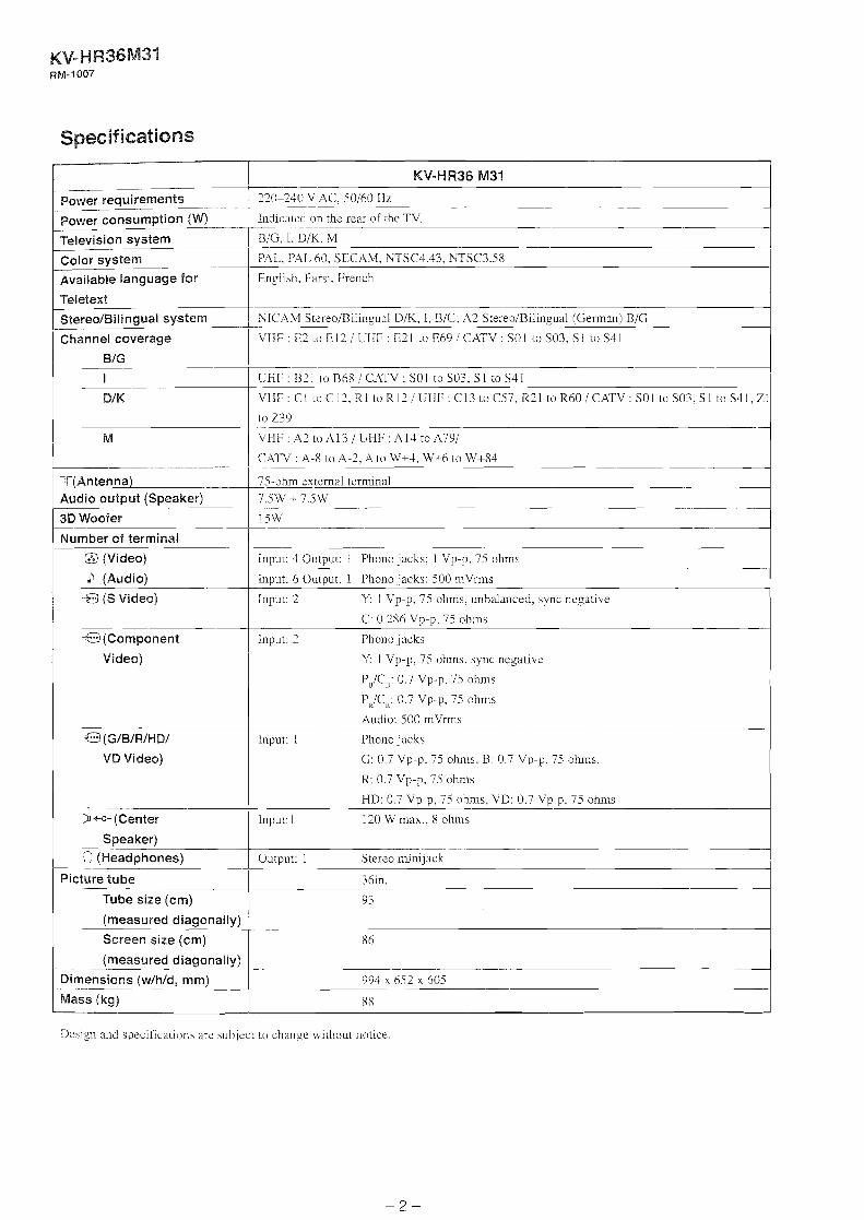
Specifications
KV-HR36 M31
320-240 k 4C , 50160 Hz --
Power ~ ~ f l ~ ~ m p t i ~ f l (W) Ind~cateci on the rear of the T V
BIG, 1. DIK. M --
Color system PAL, PA1 60. SECtlM, \TSC4 43. -WSC3 58
Available language for / English. Farsi. French I Teletext
Stereo/Bilinaual system XICAM Sti.reo/Bilinpual DjK, I. BIG: A3 Stereo/Bilinpual [German) BjG -
Channel coverage 1 VHF E2 LO EII I CHF E21 to h69 I CATV sol to s03, sl to s41 I
VHF: CI t o C 1 2 . R l t o R 1 2 / L t l F : C 1 3 toC57 .R21 toR60!CATk-: SO1 toS03 .S I t oS41 ,ZI
;T(Antenna) 75-ohm external terminal -
Audio output (Speaker) 7 . W + 7.5W .- I 3D Woofer w
-- 1 )Number of terminal
Q (Video)
b (Audio)
-53 (S Video)
+D (Component
Video)
-f&J (G/B/WHD/
VD Video)
D +c- (Center
Speaker)
2 (Headphones)
Picture tube
Tube size (cm)
(measured diagonally)
Screen size (cm)
(measured diagonally)
Dimensions (wlhld, mm) - .-
Mass (kg)
Input: 4 Output: ! Phono jacks: I Vp-p. 75 ohms
Input: 6 Output: 1 Phono jacks; 500 mVrms
Input: 2 Y: 1 Vp-p. 75 ohms, unbalanced. sync negative
-- C: 0.286 Vp-p. 75 ohms
Input: 2 Phono jacks
Y: 1 Vp-p, 75 ohms. sync negative
P,/C,: 0.7 Vp-p. 75 ohms
P,IC,: 0.7 Vp-p. 75 ohms
Audio: 500 mVrms
Inpu~: I Phono jacks
G: 0.7 Vp-p, 75 ohms, B: 0.7 Vp-p. 75 ohms.
R: 0.7 Vp-p, 75 ohms
-- HD: 0.7 Vp-p. 75 ohms. VD: 0.7 Vp-p. 75 ohms
Input: I 120 W max.. 8 ohms
Output: 1 Stereo minijack
iksign and specifica~ions are subject to change without notice.
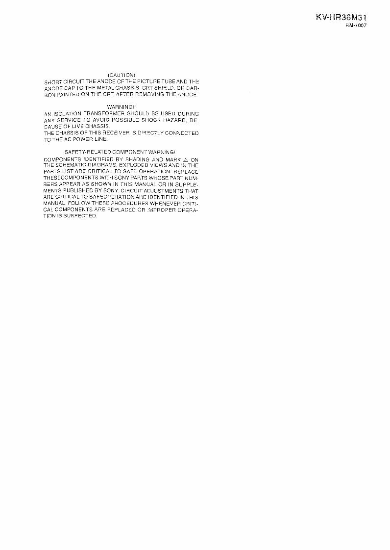
(CAUTION) SHORTCIRCUITTHE ANODE OFTHE PICTURE TUBE AND THE ANODE CAP TO THE METAL CHASSIS, CRT SHIELD. OR CAR- BON PAINTED ON THE CRT, AFTER REMOVING THE ANODE.
WARNING!! AN ISOLATION TRANSFORMER SHOULD BE USED DURING ANY SERVICE TO AVOID POSSIBLE SHOCK HAZARD, BE- CAUSE OF LIVE CHASSIS. THE CHASSIS OFTHIS RECEIVER IS DIRECTLY CONNECTED TO THE AC POWER LINE.
SAFETY-RELATED COMPONENT WARNING!!
COMPONENTS IDENTIFIED BY SHADING AND MARK A ON THE SCHEMATIC DIAGRAMS, EXPLODED VIEWS AND IN THE PARTS LIST ARE CRITICAL TO SAFE OPERATION. REPLACE THESECOMPONENTS WITH SONY PARTS WHOSE PART NUM- BERS APPEAR AS SHOWN IN THlS MANUAL OR IN SUPPLE- MENTS PUBLISHED BY SONY. CIRCUIT ADJUSTMENTS THAT ARE CRITICALTO SAFEOPERATION ARE IDENTIFIED IN THlS MANUAL. FOLLOW THESE PROCEDURES WHENEVER CRITI- CAL COMPONENTS ARE REPLACED OR IMPROPER OPERA- TION IS SUSPECTED,

TABLE OF CONTENTS
Section Page Section ...
Title Page - .
.................................. 1 . SELF BlAGNOSlS FUNCTION . 5 5 . SAFETY RELATED ADJUSTMENTS
2 . DISASSEMBLY
.... ........................... REAR COVER ASSEMBLY .. 9 ............................................... CHASSIS ASSEL;TBLL 9
............................................... SERVICE I'OSRIOS 9 .................................... SPEAKER BOX ASSEMB1.Y 9
T AND UG BOARDS ............................................. 1 0 RL1 AND LI(; BOARDS ......................................... 10
............................................................... ABOARD 10 .............................. ............................ D BOARD .. 11
............................................................... SF BO>\RD 11 H3. H4. H5 AVD H41G BOARD ............................. 11 I IXRNESS ARRi'&GE"VIENT ................................. 12 REh1OV.kL OF KVODE-CAP .................................. 13
CRT ........................................................................... 14
3 . SERVICE MODE
3- 1 . IMETHOD 01' SETTING THE SERVICE ADJUSTMENT MOD1 '. ............................................ 15
3-2 . SERVICE LIODE ADJUSTiMEXT ........................... 15 3 MEMORY WRITE COXFIRM-ATION METHOD .. 15
......... 3.4 . ADJL'STTI\;G RLTTONS AND DiDICATOR 15 3.5 . SERVICE MODE L, IST ............................................ 16
................. 5- 1 . +I3 .X 4 X VOLTAGE CONFIRMIWTION 56 ....... . 5.2 HV REGLi14ATION ClRCLTIT ADJUSTMENT 56
......... 5.3 . HV PROTECTOR CIRCLV ADJUSTAM ENT 56 5.4 . IK PROTECTOR CIRCUIT CHECK (D BOARD) . 56
6 . DIAGRAMS
6- 1 . BLOCK DIAGRAM (1) ........................................ 57 ........................................ BLOCK DIAGR4M ( 2 ) 59
BLOCK DIAGR4M (3) ........................................... 61 BLOCK DIAGRtLM (4) ........................................... 63 BLOCK DIAGRAM (5) ........................................ 65 BLOCK DIAGFUM (6) ........................................... 67 BLOCK DIAGRAM (7) ........................................... 69 BLOCK DIAGRAM i 8 ) ........................................ 71 BLOCK DIAGRAM (9) ........................................ 73 BLOCK DIAGRAM (10) ........................................ 74
.......................................... BLOCK DIAGRAM (11) 75 6-2 . CIRCUIT BOARDS LOCATIOS ................................. 76 6.3 . PKLNTED WIRLWG BOARDS AND SCHELMA TIC
DI.4GRAMS ................................................................ 76 6.4 . SEMTCONDGCTORS ................................................ 173
7 . EXPLODED VIEWS
7.1 . CHASSIS SECTION .......................................... 175
4 . SET-UP ADJUSTMENTS 7.2 . SUPER WOOFER BLOCK ................................... 176 7.3 . CRT SECTIOK ....................................................... 177
4- I . LVTWI.IZING SFC DAT.4 .................................... ... 47 7.4 . BEZEL. SECTION ................................................ 178 4.2 . BEAM Id~LVD14;Ci ................................................... 47
.......................... 4.3 . COhWERGEXCE ADJUSTMENT 48 ..................................... . ................................ . 4.4 G2 (SCREEN) ADNSTMEXT 50 8 ELECTRICAL PARTS LIST 179
4.5 . FOCUS ADJUSTMEN 1 ...................................... 50 4.6 . hRCK ASSY TWIST .ADJUSTMENT ..................... 51 1.7 . SFC COARSE i1DJUSTMENT ................................ 5 1
................................... 4.8 . SFC FINE ADJL-STMENT 53 4.9 . P&P SUB CONTRAST ADJlJSTMENT (VIDEO) .. 54 4.10 . PBP SUB-HLE AND SLB.COI, OR
ADJUSTMEAT (VIDEO) ......................................... 54 4- 11 . WHITE BXLAYCE ;\DJUSTME?J?' ....................... 55
........................................ 4- I 2 . FOCUS AD.JCSTMENT 2 55 .............. 1- 13 . PICTURE DISTORTION ADJUSTMENT 55

SECTION 1
SELF DIAGNOSIS FUNCTION I . Summary of Self-Diagnosis Function
* This device includes a self-diagnosis function.
In case of abnom~alities. the 'oindicator automatically blinks. It is possible to predict the abnormality location by the number
of blinks. The Instruction Manual describes bhlking of the mindicator . * If the symptom is not reproduced sometimes in case of a malfunction, there is recording of whether a malfunction was gener-
ated or not. Operate the remote command to confinn the matter on the screen and to predlct the loc'lt~on of the abnormd~t>.
2. Diagnosis Items and Prediction of Malfunction Location
When a malfunction occurs t h e n i n d i c a t o r only blinks for one of the following diagnosis items. In case of two or more
malfunctions, the item u h c h iirst occurred blinks. If the malfunctions occurred simultancously. the item with the lower blink
count blinks first.
The screen display displays the results regarding all the diagnosis items listed below. The display " 0 " means that no malfunc-
tions occurred.
1 Nunrber+tmes ~ Diagnosis Item ---
1 indicator b M s Probable Cause Location I Detected SJ mptoms
1
+B overcurrent IOCP) 1 2 times 1 78001 (FBTl Rare sllort-circuit etc. (D board) entered standby mode.
1 Q5001 (H-OUT), Q5006 iD board) [Relay is off when the power
! I turns on.)
1 +B loau open iD board) R6570 O p e C p - ~ 1 +B overvoltage IOVP) 3 times I PH8003, control system malfunction L2603 1 Has entered standby mode.
Open .
Vertical deflection stopped --101(< OUT) (D boadj IC401 ~ ((V-STOP) 1 4 times 1 (CXA2170Q) (MJ board) 1 Has entered standby mode.
i 5 times VTDEO OLT IC malfunction IC9001, 9002. Ill error M i B L i O i ) 9003 (C board) IC1.01 (CX42170Q) Has not entered standby mode ( iMJ board) -- --- 4 Sub power supply system load shorted etc I 6 times
I
I 1 [A board) Has entered standby mode
I I Horizontal deflecnon IC401 (CXA2150Q) (MJ board) Q5404 1 1 stopped (H-STOP) 1 7 nmes 1 (S-COR-OUT), Q5001 (H-OUT). Q5006 Has entered standby mode.
I . I I
Audlo Protector I 8 hmes ' IC1-000. 2001 malfuncuon (A board) ) Has entered standby mode I
tfigh-Voltage stopped I T8001 (FBT) rare short-circu~t (D board', (HV-PROT)
10 tlmes IC8002. Q8013.8014. R805I (D board) Has entered mode
( Zero Cross DET emor 9 tlmes RYhO00 Power relay meltlng down (A board) ' Has not entered standby mode (
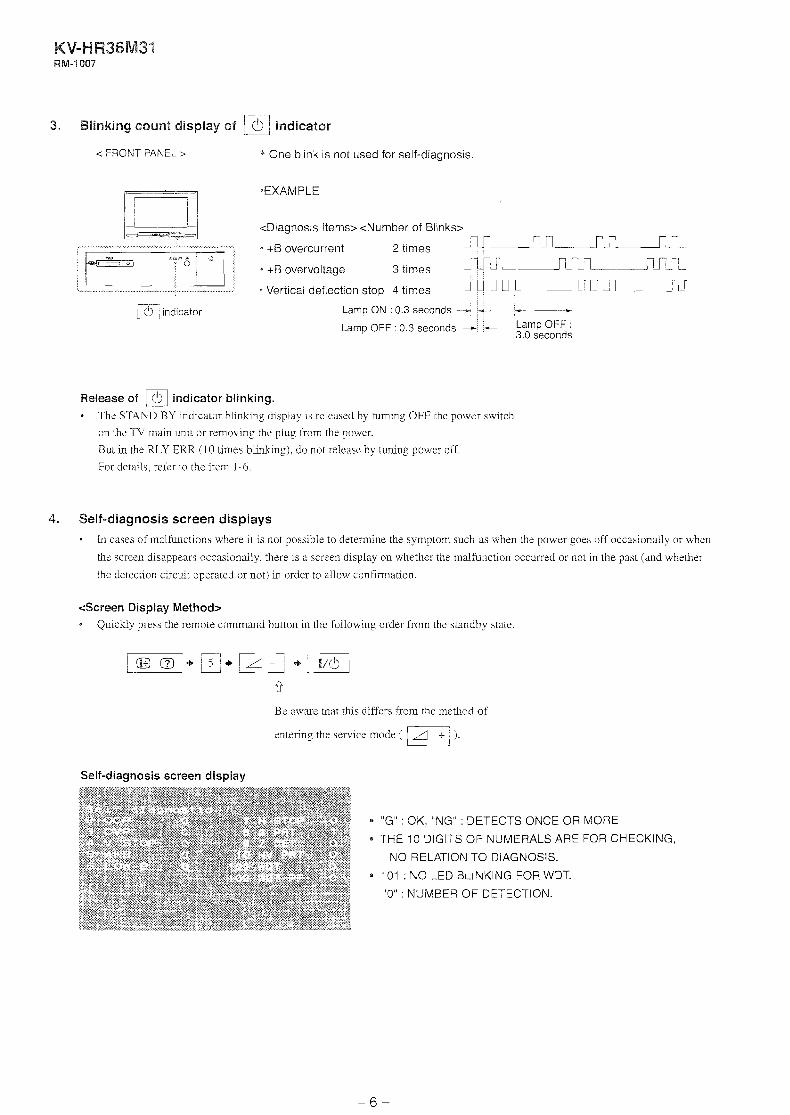
rl 3. Blinking count display of / indicator
< FRONT PANEL > * One blink is not used for self-diagnosis
<Diagnosis Items> <Number of Blinks>
+B overcurrent 2 times J A A L +B overvoltage 3 times d r ~ r ~ . . , .
Vertical deflection stop 4 times -~.J~JJ-A~~~.JJI %- - a ~ndicator @A' Lamp ON : 0.3 seconds -- ;- +----;
Lamp OFF : 0.3 seconds - - 3.0 Lamp seconds OFF :
Release of indicator blinking.
The STAYD BY indicator b l i n h g display is released by turning OFF the power switch
on the TV main unit or removing the plug from [he power.
But in the RLJY ERR (10 times b l i n h g ) . do not release by tuning power off.
For details. refer to the item 1-6.
4. Self-diagnosis screen displays
In cases of malfunctions where it is not possible to determine the symptom such as when the power goes off occasionally or when
thc screen disappears occasionally, there is a screen display on whether the malfunction occurred or not in the past (and whether
the detection circuit operated or not) in order to allow confirmation.
<Screen Display Method> Quickly press the remote command button in the following order from the standby state
Be aware that this differs from the method of
entering the service mode ( r/1+/ )
Self-diagnosis screen display
"G" : OK, "NG" : DETECTS ONCE OR MORE
THE 10 DIGITS OF NUMERALS ARE FOR CHECKING,
NO RELATION TO DIAGNOSIS.
101 : NO LED BLINKING FOR WDT.
"0" : NUMBER OF DETECTION.

5. After the self-diagnosis operation
. The results &splay is not automatically cleared. In case of repairs and after repairs. check the self-diagnosis screen and be sure
to return the results display to " O ". . If the results display is not returned to '' 0 " it will not be possible to judge a new malfunctio~l after completing repairs.
<Method of Clearing Results Displap
1. Power off !Set to the standby mode)
z. l"lo_l + + 1x1 + r-1 (Service Mode)
3. Channel @ * (Test reset = Factory presel condition)
<Method of Ending Self Diagnosis Screen> When ending the self-diagnosis screen completely, turn the powcr switch OFF on the remote commander or the main unit
AUDIO PROT (FROM A BOARD)
LOW-B ERR (FROM A BOARD) 1
HV-PROT (FROM D BOARD) -1 I 1 MJ BOARD -
ov P FROM A, D BOARD)
MAIN MICRO-
AC-RLY MICRO- (TO A BOARD) COMPUTER
IC102 OCP
i ~ ~ n h h A n nnnnn) CXA-2170Q
V,
* 12C YCJ RETURN DATA
BLINKING TIMES LED 1 SYMPTOM
+B OCP +B OVP V-STOP AKB LOW-B ERROR H-STOP
AUDIO PROT Z DET HV PRT

+B OCP
+B OVP
V-STOP
A m
LOW-B ERROR
13-STOP
LV. D. T.
AUDIO PROT
HV-PROT
Z DET
If the ICY01 Pin 11 (+B OCP DET) is h g h 2 seconds, turn AC-REl.AY low (P-OFF) and make STAVDBY
LEU hlinks twice.
If the IC701 Pin 15 (+B OVI' DET) is high 2 seconds. turn AC-FGLAY low (P-OFF) and make STANDBY
LED blinks three times.
If the return data Bit0 (VNG) from CXA2150Q is "1" while 2 seconds. turn AC-RELAY low (P-OFF) and
inakc STANDBY LED blinks four times.
If the return data Bit2 (IKREF) Erom CXA2 1SOQ is "0" and there is no chanze for 20 seconds, make
ST.4,XDBY LED blinks five times.
At this time, AC-RELAY continues to high.
If the IC701 Pin 69 (AC-RELAY) is high and the Pin 43 (LOW-B ERfiOR DET) is low while 5 seconds.
turn AC-RELAY low (P-OFF) and make STANDBY LED blinks six times.
If the return data Bit1 (HNG) from CX42170 is "1" while 2 seconds, turn AC-RELAY low (P-OFF) m d
make STANDBY LED blinks seven times.
Obsenies the watch dock timer (BUS COMMLWIC!iTION ERROR DET) bus communication. If errors are
detected, counts up and reform the bus communication and displays the number of time.
(No LED blinking).
In case of Pin 85 of ICSOl (AUDIO PROT DET) turns high 60msec twice at a time. makes AC-RELAY
turns low (Power off) and STANDBY-LED blink 8 rimes.
In case of Pin 33 of IClOl (HV-PROT DET) Lurns high 10 seconds conrinuously in normal operation or in
BS fixed Stand-by, makes AC-RELAY turns low (Power off) and ST,L\NDBY-LED blinks 10 times.
There are two causes for Zero Cross Error.
?Jormally the pulse doubled AC power supply frequeny is fed to Pin 8 of ICIOS. But in case of the
abnormal pulse is fed. it makes AC-RELAY turns low (Power offj and STAYDBY-LED blinks 9
times.
Jii this case, "1" is nor displayed in '9. Z DET' column in the self-diagnosis mode.

SECTION 2
DISASSEMBLY
2-1. REAR COVER ASSEMBLY 2-3. SERVICE POSITION
@ Four screws (+BVTP 4x1 6) I
,
1 , bottom.
v -C 'L '~ Three screws (+BVTP 4x1 6)
P Jqb Screw (i-BVTP 4x1 6) A support
d Three screws (i-BVTP 4x1 6)
2-2. CHASSIS ASSEMBLY 2-4. SPEAKER BOX ASSEMBLY
@ Two screws (+ TWHTP 4x25)
4 Connector
@ Speaker
assembly
box

T AND UG BOARDS
@ Two connectors
@ Screw ---------
i @ T board
2-6. BM AND MG BOARDS
2-7. A BOARD
BM board (with MS2 board)
@ Connectors
CN6100 CN6101 CN6006 ',, CN6010
9-0 Three screws (+BVTP 3x1 2)
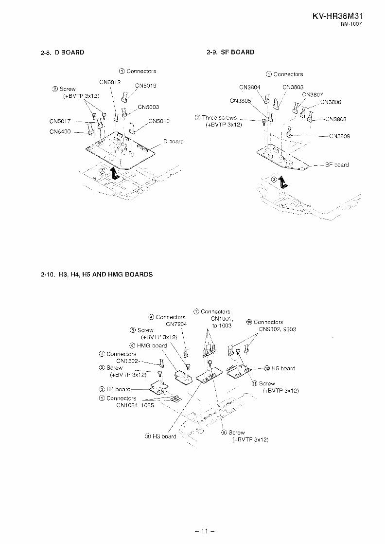
2-8. D BOARD 2-9. SF BOARD
@ Connectors @ Connectors
@ Three screws , (+BVTP 3x1 2) ,
". ' L. L C N 3 8 0 9 -. /',
SF board
2-10. H3, H4, H5 AND HMG BOARDS
@ Connectors Cnnn~rtnrs
CN1OO1 @ Connectors to 1003
h CN9302, 9303
- - - , . . . - - . - , - CN7204
@ Screw \
@ Connectors
O Screw (+BVTP 3x-8
/ \O Screw
@ H4 board --- I+RVTP 3x1 ?\
@ Connectors CN1054, 1- , ,
H5 board

2-1 1. HARNESS ARRANGEMENT
CN6006
CQIL,NA ROTATION
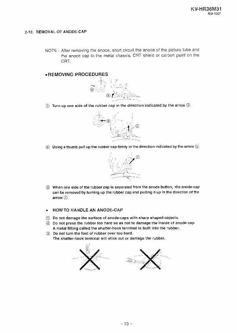
2-12. REMOVAL OF ANODE-CAP
NOTE : After removing the anode, short circuit the anode of the picture tube and the anode cap to the metal chassis, CRT shield or carbon paint on the C RT.
*REMOVING PROCEDURES / - -6
@ Turn up one side of the rubber cap in the direction indicated by the arrow @
@ Using a thumb pull up the rubber cap firmly in the direction indicated by the arrow @.
@ When one side of the rubber cap is separated from the anode button, the anode-cap can be removed by turning up the rubber cap and pulling it up in the direction of the arrow O.
a HOW TO HANDLE AN ANODE-CAP
@ Do not damage the surface of anode-caps with sharp shaped objects. @ Do not press the rubber too hard so as not to damage the inside of anode-cap.
A metal fitting called the shatter-hook terminal is built into the rubber. @ Do not turn the foot of rubber over too hard.
The shatter-hook terminal will stick out or damage the rubber.

2-13. CRT
NOTE: After removing the anode, short circuit the anode of the picture tube and the anode cap to the metal chassis, CRT shield or carbon paint on the CRT.
@ Speaker box assembly coil
9 Chassis assembly
/
1 \/ C- \
w, Neck assembly
@ Anode cap (Crown washer +TP /

SECTION 3
SERVICE MODE
3-1. METHOD OF SETTINGTHE SERVICE ADJUSllVlENT 3-4. ADJUSTING BUTTONS AND INDICATOR MODE
-- - I/&
SERVICE MODE PROCEDLIRE 1. Standby mode. (Power o f )
2. r@m-+- + r-l-+ rm! on the Remote Commander.
(Press each button within a second.)
3-2. SERVICE MODE ADJUSTMENT
Item NO (reg~ster name)
Category Data
3. The SCREEN displays the item being adjusted.
4. Press or on the Remote Commander to select the
adjustment item.
5. Press or on the Remote Commander to change the data.
6. Press or a on the Remote Commander to select the
..
Adjustment item up '
Adjustment item down
category.
7. If you want to recover the latest values press then ~ T R / I P to read the memory
8. Press 'iLVB3G then to write into memory.
9. Turn power off.
Note: Press then on h e Remote Commander to initialize
or turn set off and on to exit.
3-3. MEMORY WRITE CONFIRMATION METHOD 1. After adjustment, turn power off with the remote commander.
2. Turn power on and set to Service Mode.
3. Call the adjusted items again and confirm they were adjusted.

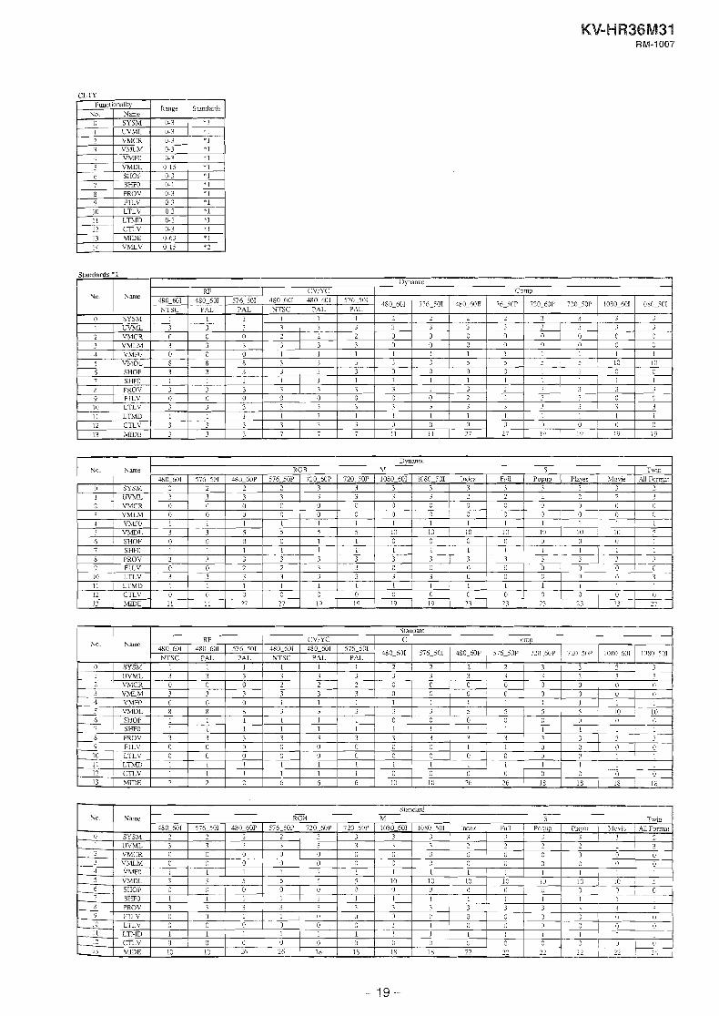
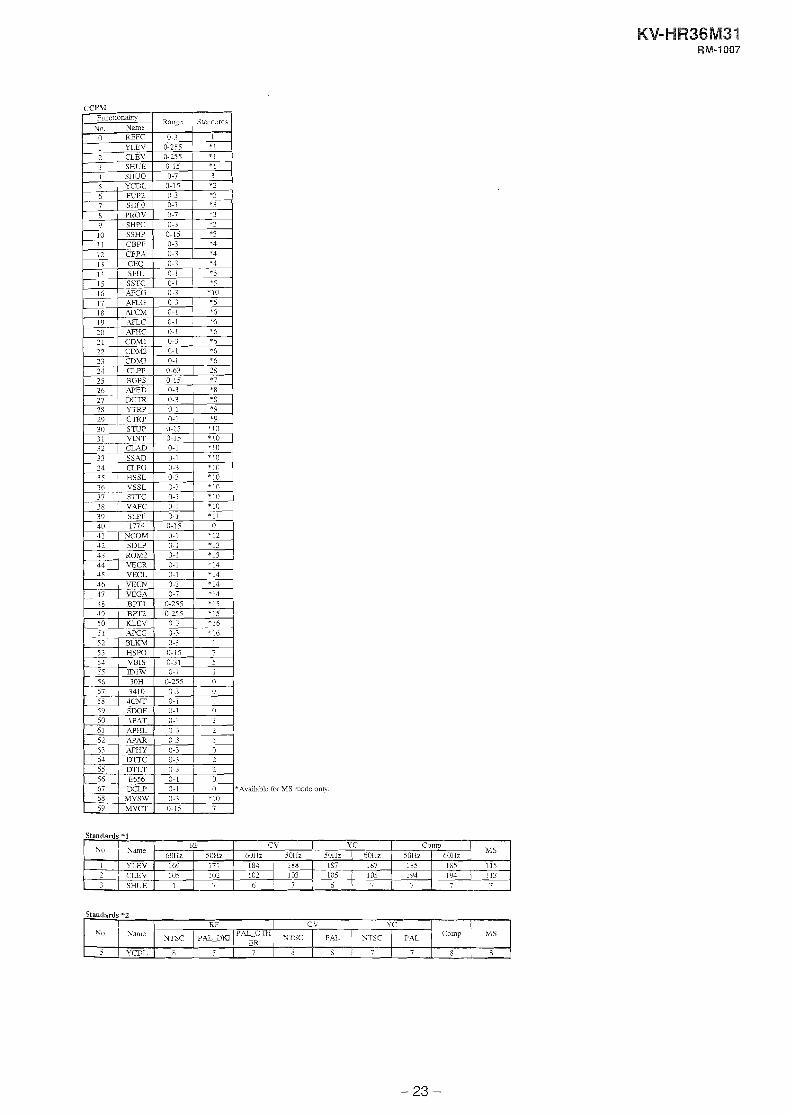
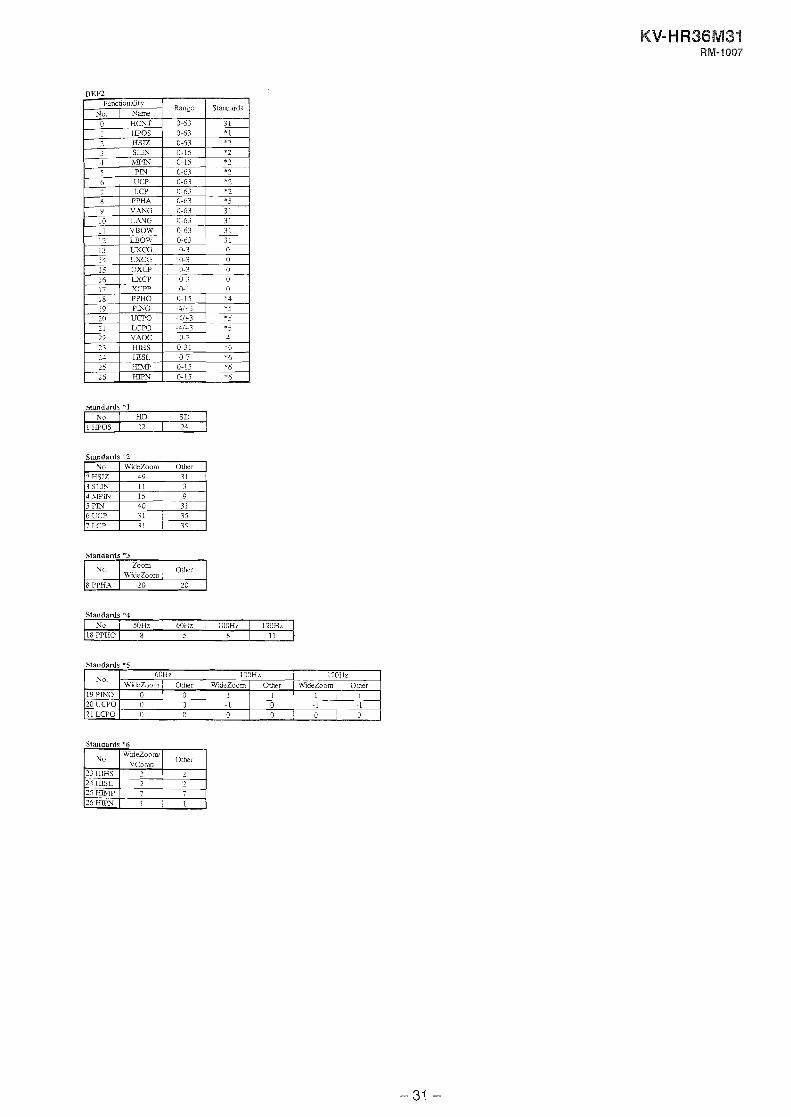
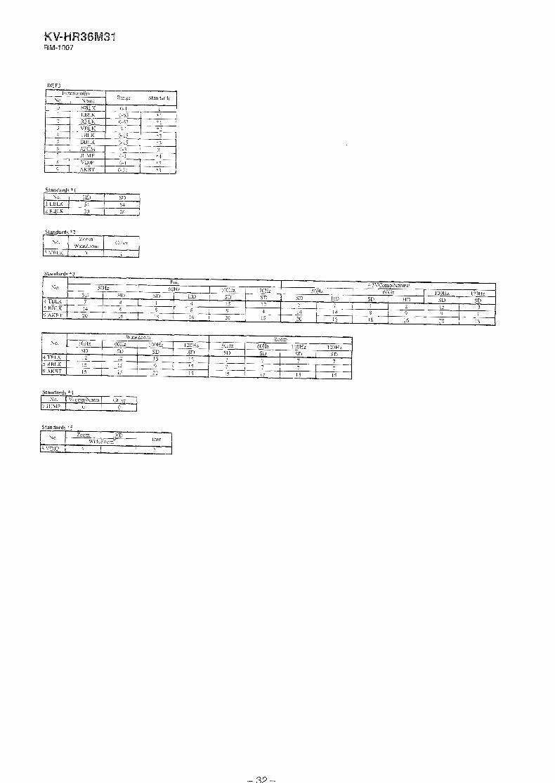
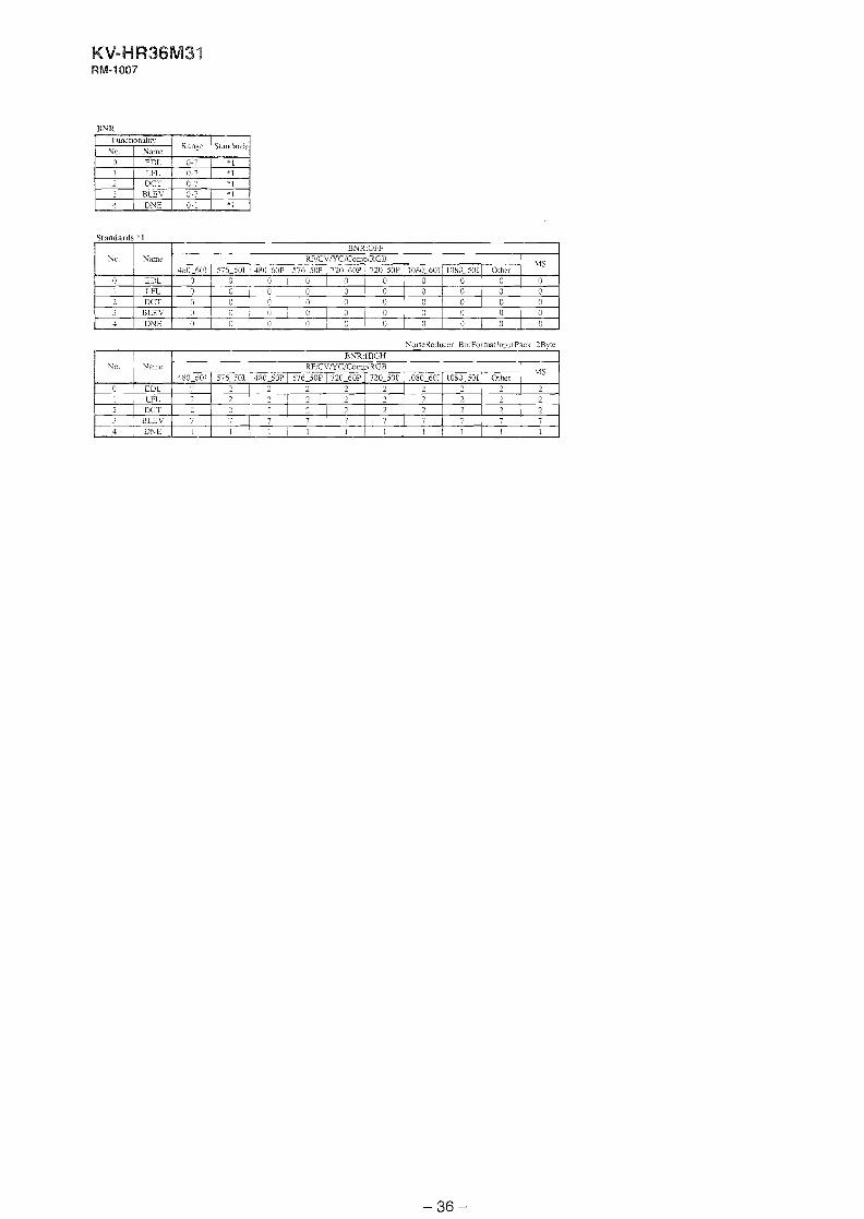
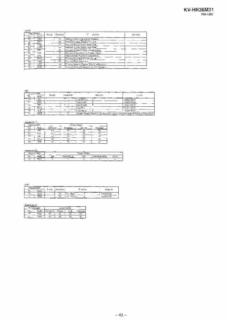
3-5.SERVICE MODE LIST
Standards *l RF ' CV I Y C : CO>fP
So. Same
Standards ' -2
Standards *3

Standards $1 a r i c-v I ~ r - 1 rnw
RGH i >IS I Twin

Standards *3
t SHFO 1 1 1 1 1 - 1 1 1 I 1 ! l 1 1 1 1 ~~~~~~
8 1 PROV 3 3 3 3 3 v 3 3 > '1 --- 9 F l L V 0 0 0 0 0 0 1 0 0 1 1 0 0 0 0 i n i n x i n n n n n n l n n n n n
Functionality NO. xame n I SYSLf I 0-3 I - 1
Rarige Standards

Standards *2
10 IT'LV 0 0 0 J C 0 0 0 0 0 0 11 12
13
LTMD CTL.V l i D E
i 0 0
r j 0
I 0 0
1 1 0 1 0 4 1 4
I 0 4
I 3 8
3 X
I 0 24
1 0
24
1 0 16
I 0 16
I 3 16
I
0 16

7 ( 5 ! U 4
1 0 0 1 0 0 1 0
I? n o l n n 1 I n l n n n
for 41s mode only.
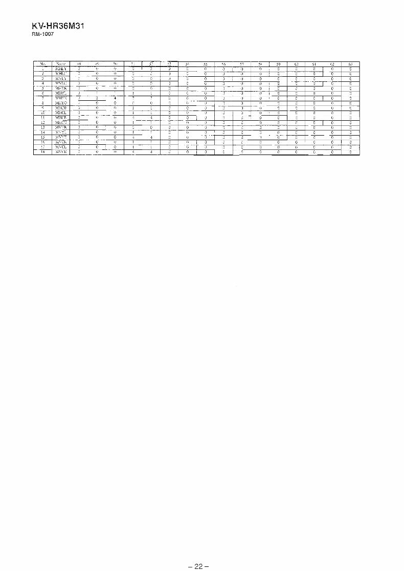
Standards *I

Standards *3
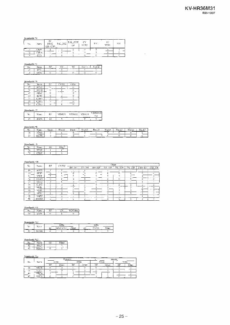
Stnndards *?
Standards $5
Standards *6
Standards ^7
*I
Standards *8
No 17 18 1 9
0 2 0 (1
30 I! 22 23
Standards *9
YTW 15 CTRP
R F 0 0 n
?lame AFLG tU-CZI ~ i 7 r
Standards *10
AIHC CD.M! CDlf3 CDM3
Standttrds *11 No 1 V m c I RF 1 LV I YClOther 39 1 SLPF I 0 1 0 1 0
CVNC 0 0 ri
Standards '12
Other 0 0 I)
0 2 0 0
0
(i
0
Standards *13 No Name I SD 1 Other 1 2 / CDLP ( 1 1 0 13 1 ROM2 I 0 1 0
No.
Standards '14
1 l N C O M I 0 0 1 0 1 \I 0 1 0
Name ~ O H Z I 5nwz
Rt ' 1 BS1CVfl.C Other 1 RF I CV/YC ( Other
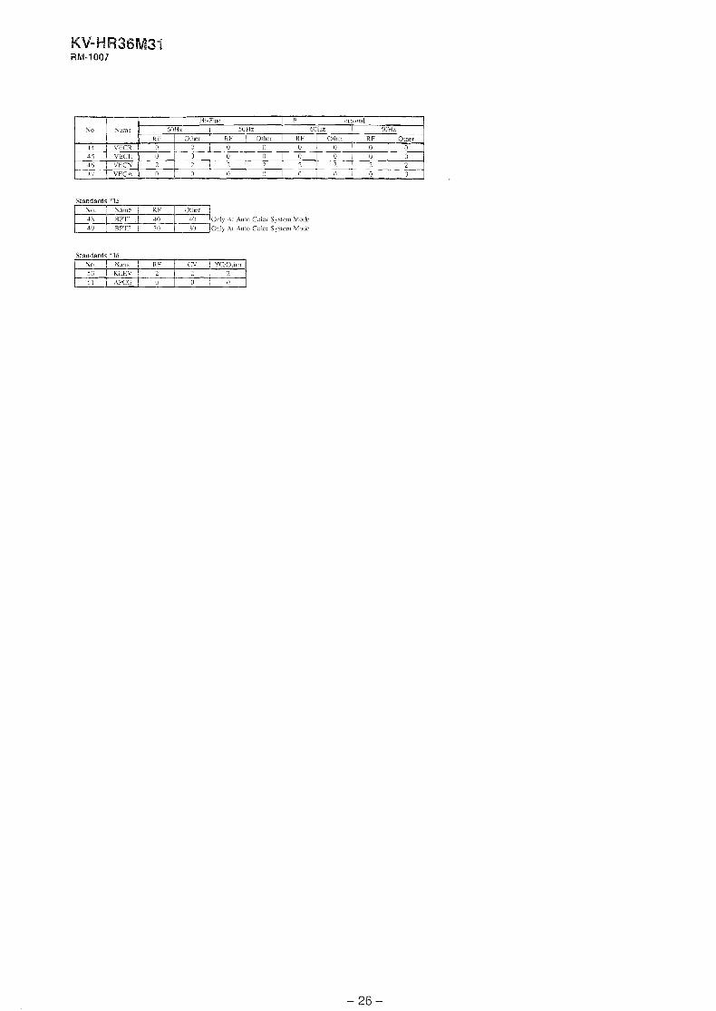
Standards *l5
Oiily At Auw Calor SysIem Mode Only At Auto Color System Mod:
Staudards *I6
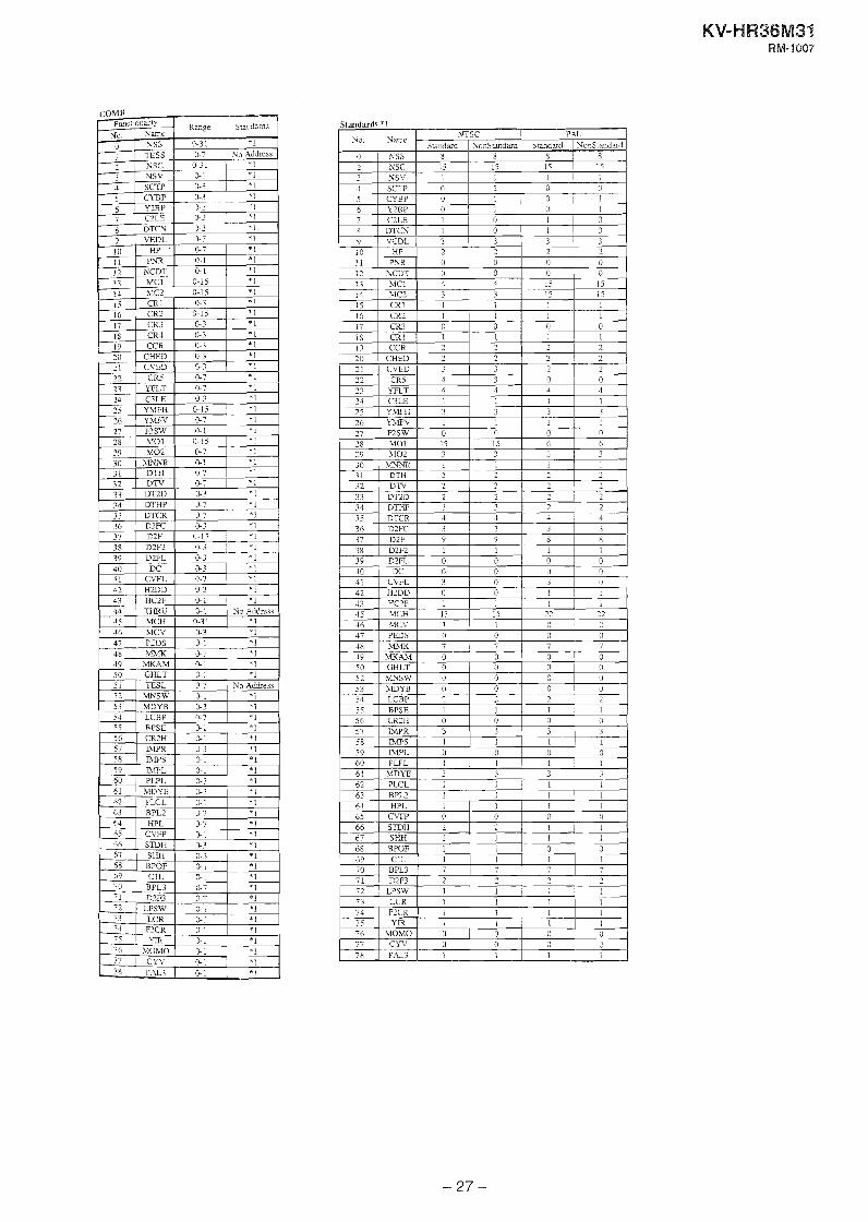
COMB Functionabt? Range Standards
35 DTCR 1 1 36 DZFC 3 3 3 3 37 D2F 9 4 S 8
41 ~ C V F L ~ 3 1 o 1 3 1 0 42 1 HlDD ( 0 1 I I . . . - - - 0 1
49 50 52 53
MKMM GHLT MNSW bWYE
- 0 0 3 0
0
- 0 0 3
0 0
0 0
010 0 0

Standards *I
Standards *1
Stmdards ' 2

MCY

Standards *l
Standards $2
F\iacncna~ny X<>. 1 Srn
0 1 VPOS ! 1 VSlZ 3 1 VLIX j 1 vsco 4 1 VCEN 5 / VPIX 6 1 NSCO 7 / I m Z 8 1 ZOOM 9 / .*SW
Standards *3
Ranv~
0-63 0-63
-13 o-ij- '3-b3 0 - 7 1
10 ; I 1: 13 14
Standard* *S
Sr.w.d;udi
24 I I 3
-- - '1 - 31 -3
-\SPT SCRL CVLV
LVLS VPSO
Standards *6
0-63 1 3 i 0.31 / 15 0-1 - - * 3 0-! -1 3-67 1)-53 0.15 ---- 0-15 0-15
-5 * 5 *I:
*5 *7
20 1 UCPO I -JIt? ( =5 1- -. --- - 22 / V4OC 1 0-7 1 I 23 i HIHS I 0-31 1 *6
Standards *2
Standards *4
Standards ' 5
Standards *1
Standards *?
Standards "5

MID I
Standards *I No. ( Single 1 Other
O D Y C D I 2 2
"" - So. I Sin@e(Norm) 1 TwiwFrecz 1 >IS 1 Index
1 DYSD I 1 1 1 1 1 1 0
Standards *3
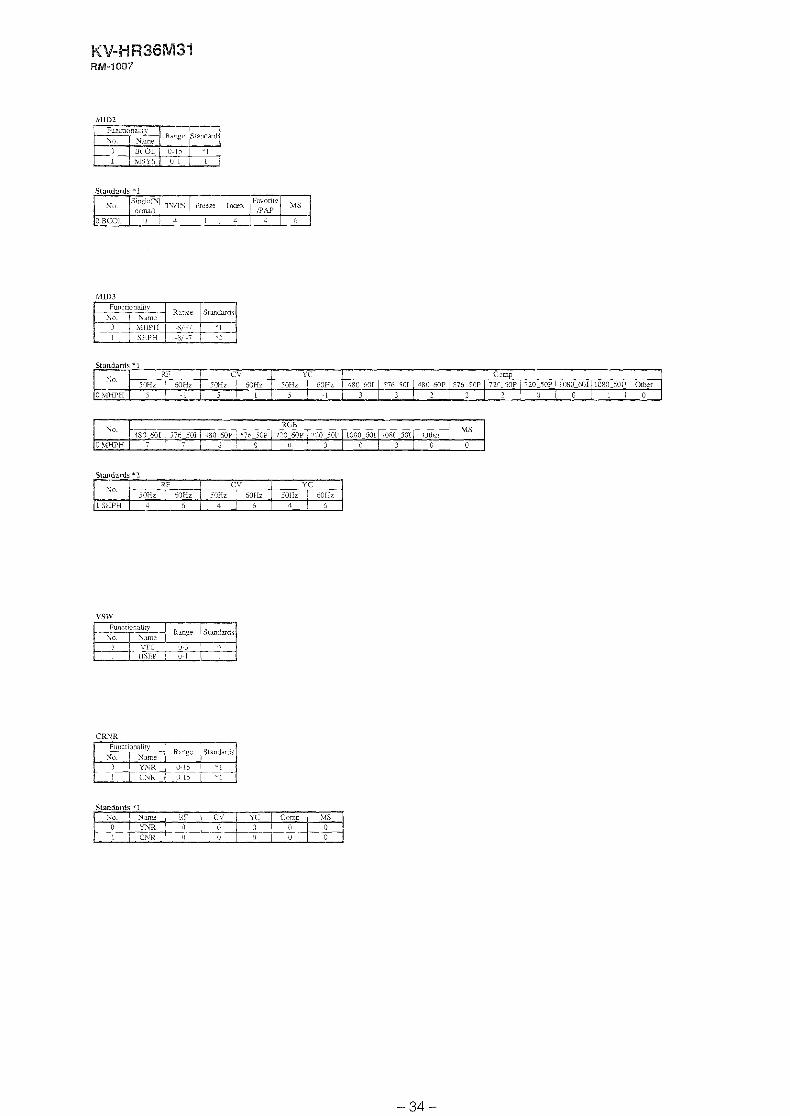
WD?
Standards * I
Standards "I
Standards * 2
VSW
CRNR
Standards '1
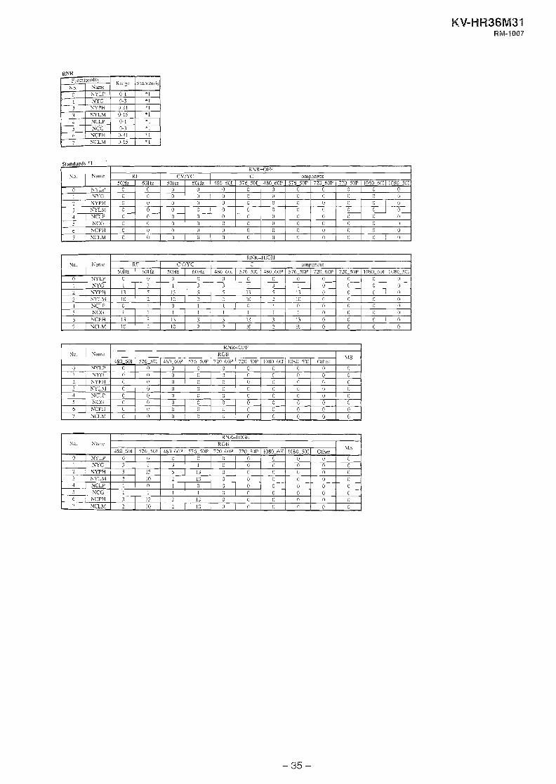
RNR
c,nnrtnmIs * I
Standard* 'I
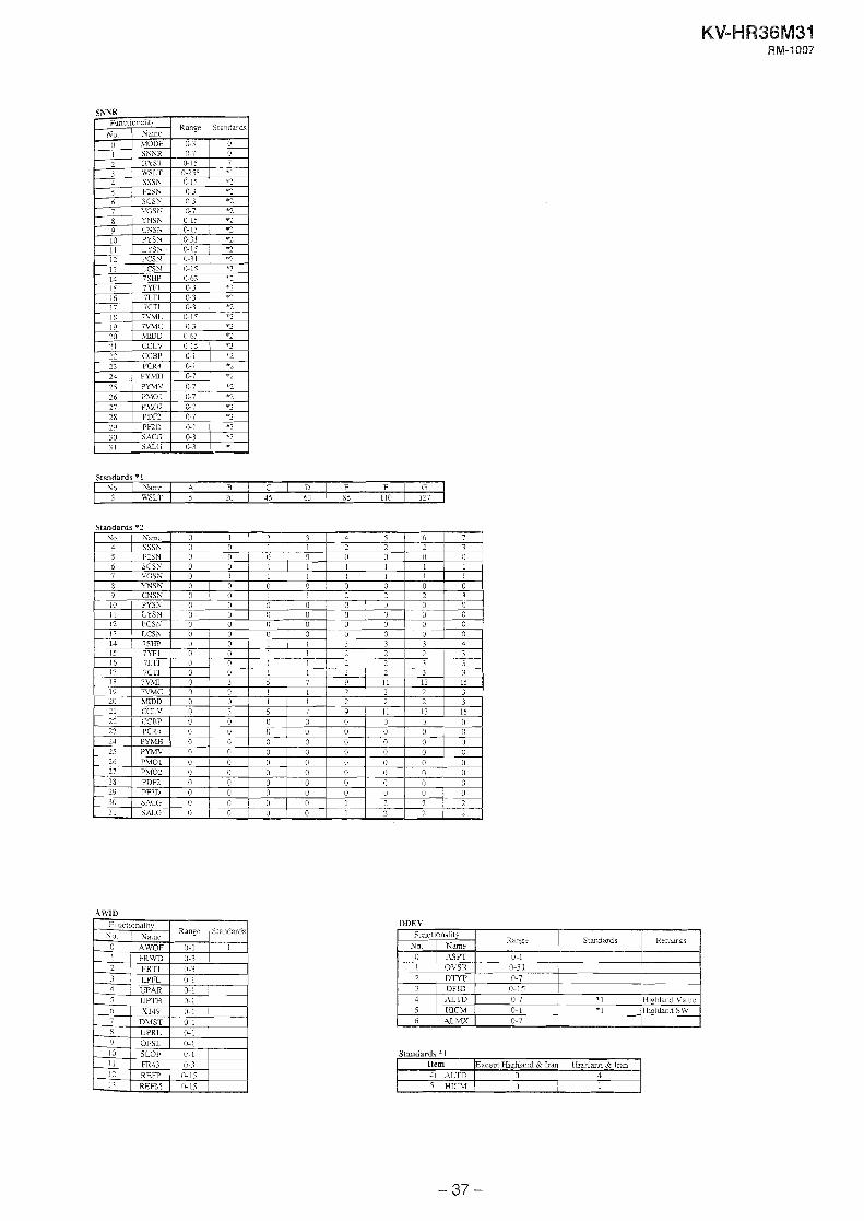
SNNR
Standards *1 N o . N a m t I A 1 B 1 C I D 1 E 1 F 1 G
3 1 WSLII. 1 5 1 20 1 45 1 63 1 7.5 1 110 1 127
Standards *2
OFSL SLOF FRU 0--3
LL IS (L i i
1- RER
UDEV
Standards '1

Standards '1

Standards *1
Standards *4

OSDP
. S E L
VSCL
Standards - i0 Q
0 I
s 1
3 2 i 0 8 0 6
Functionalin Rmpz
0 - 1 1 - j
4
j
6 7 8 - 9 10 11 - 12
Funcrionaiiy Rmge
5 O-!i 0-15 1 0 - '1-15 1 ---- 0-31 3 0-31
Yo. I;
1 ? 3 1 j
7 7 S
- 9 is 11
TC1 Tc2 TC7 V D l V D ? WD3 \TO4
Y L T l Y i 3 - 3 YLV3 11s
CSPK
Stanfiards
: -
? 0 5 i>
4 16 18
/I
Same TI21 T i 2 77.3 V I D l VID? VID? vma
' I Y W ? --- YCi'! ,ATSC SECM
0 1 5 5 !&I5 O-15
ij & ! 5 0-15 0-15 &I5 (t15 0-15 1 -- &I5
0-31 I 0 1 1 17
Standards $2 No. 1 Kame I Othei 1 RF
F 1 1 1
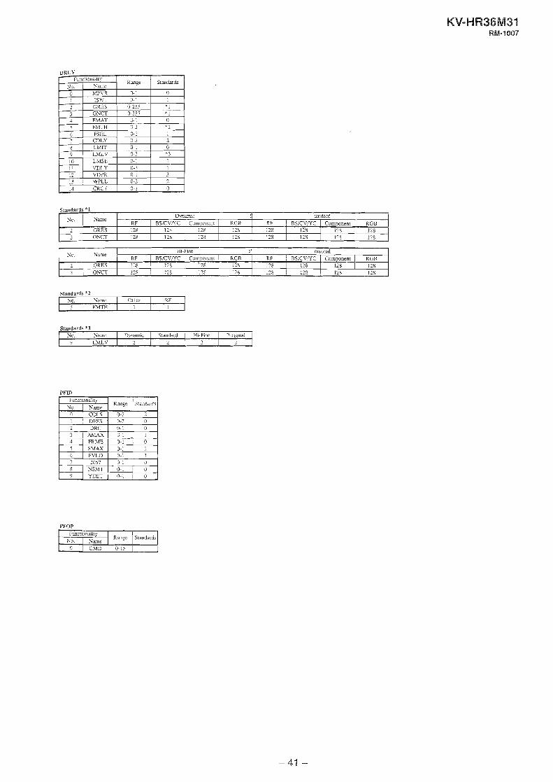
DRCV
Standards *3 Yo 1 Vame I Dynamic I Standard 1 HI-F~ne 1 Personai
~ L M L V ~ 2 2 j ? 1 3
PFID
Stxi&&
0 - 1
"1 *l 0 /?
1
0 *3 1 - 1 3 1
0
PFOP
Range
0- 1
I 0 - I 0-255 0-755 0 1 0-3 0-1 0-3 0- 1 0-3 0- 1
lo-? 0-3 0-3 0- 1
l:unctionality
0 1 2 3 4
' 5 6
8 9 10 11 12 13 14
7 M F V R ISEl. ORES ONCT W T F\?TH
FSEL CDLY LMrl LMLV LMSL W L Y W P R W L L CKCT
KV-H W36M31 RM-1007
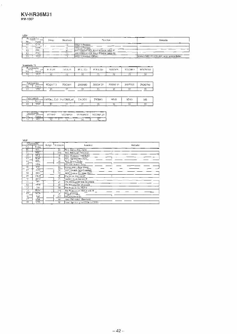
OSD
Standards *1
MSP
PIC
Standards *1
Slmdards "2
Standards *I

Standards *1
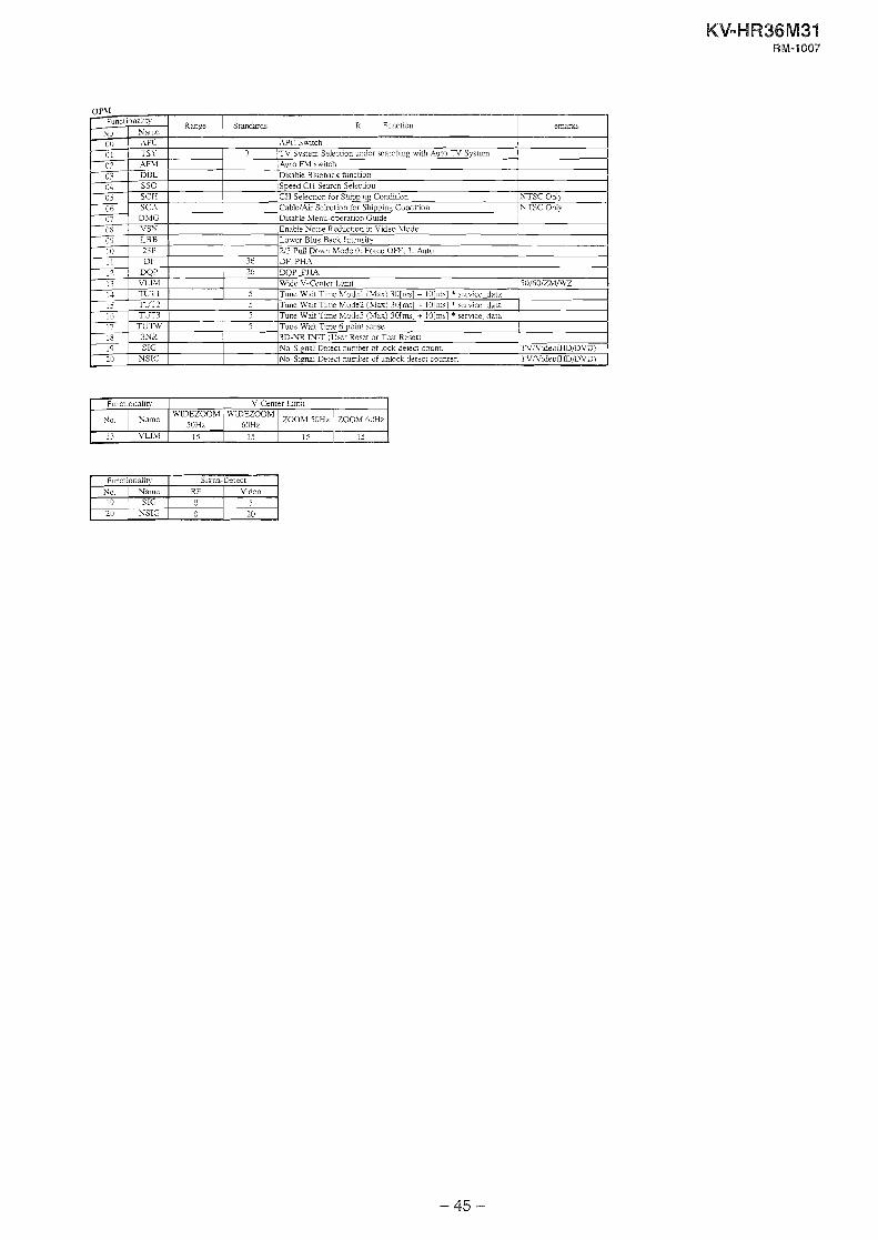
Functionaiiq
No. Name 19 1 SIG 20 1 NSIG
Signa-Detect RF 1 Video
0 5 0 20

SRY

SECTION 4
SET-LLIP ADJUSTMENTS
. The following adjustments should be made when a complete realignment is required or a new picture tube is installed. These adjustments should be performed with rated power supply voltage unless otherwise noted.
Controls and switches should be set as follows unless otherwise noted:
PICTURE control ........................................................... normal BRIGHTNESS control ................................................... normal
Perform the adjustments in the Sollowing order : 1. Beam Landing 2. Convergence 3. Focus 4. White Balance Note : Test Equipment Requircd.
1. Color-barpattern Generator 2. Degausser 3. Oscilloscope
preparation : In order to reduce the influence of gzomagnetism on the set's picture tube. face it east or west. Switch on the set's power and degauss with the degausser.
4-1. INITIALIZING SFC DATA 1. Set to the service mode. 2. Set to the coarse CONV and L,AIVD adjustment mode. 3. Move the marker in the order as shown in the figure and set
its data to "0".
Convergence: @ -+ @ 4 @ 4 @ + @
Move the marker with the buttons 7 ,I , + and -+ on the remote commander." Press "ENTER to decide the position. Change the data with the buttons 1 .1 , + and -+ on the remote commander.
4-2. BEAM LANDING 1. Input a white signal with the pattern generator.
Contrast ] norm. Brightness
2. Position neck assy as shown in Fig-l-I.. 3. Set the pattern generator raster signal to a green raster. 4. Move the deflection yoke to the rear and adjust with the pu-
rity control so that the green is at the center and the blue and the red take up equally sized areas on each side. (See Figures 4- 1 through 4-3 .)
5. Move the deflection yoke forward and adjust so that ttic entire screen is green. (See Figure 4-2.)
6. Switch the raster signal to blue, then to green and verify the condition.
7. When the position of the deflection yoke has been decided. fasten the deflection poke with the screws and DY spacers,
Neck assy
/
I- , Behind the G2 edge 1
Fig. 4-1
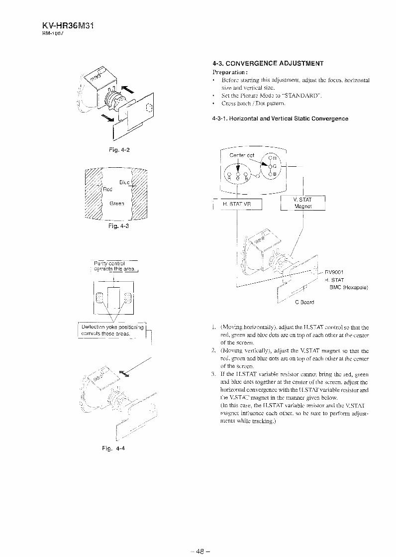
Fig. 4-2
Fig. 4-3
Purity control 1, L e c t s this area,
Deflection yoke positioning corrects these areas.
4-3. CONVERGENCE ADJUSTMENT Preparation :
Before starting this adjustment, adjust the focus. horizontal size and vertical size.
* Set the Picture Mode to "STANDARD". - Cross hatch / Dot pattern.
4-3-1, Horizontal and Vertical Static Convergence
C Board
1. (Moving horizontally), adjust the H.STAT control so that the red, green and blue dots are on top of each other at the center of the screen.
2. (hloving vertically), adjust the V.STAT magnet so that the red, green and blue dots are on top of each other at the center of the screen.
3. If the H.STAT variable resistor cannot bring the red, green and blue dots together at the center of the screen, adjust the horizontal convergence with the H.ST,AT variable resistor and the V.STAT magnet in the manner given below. (In this case. the H.STAT variable resistor and the V.STAT magnet influence each other. so be sure to perform adjust- ments while tracking.)
Fig. 4-4
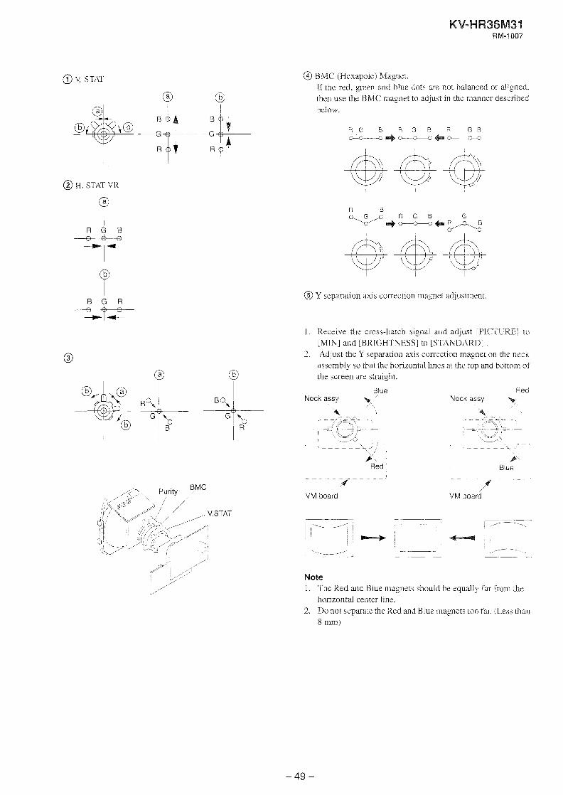
@ \! STAT
@ @
@ H. STAT VK
@
R G B
=d=
B G R
Z t i r
@ BMC (I-Iexapole) Magnet. If the red, green and blue dots are not balanced or aligned. then use the BMC magnet to adjust in the manner described below.
@ Y separation axis correction magnet adjustment.
1. Receive the cross-hatch signal and adjust [PICTURE] to [MN] and [BRIGHTNESS] to [STANDAW] .
2. Adjust the Y separation axis correction magnet on the neck assembly so that the horizontal Lines at the top and bottom of the screen are straight.
Blue Neck assy b /'
\
4 1 < - - <?+ - r
-- <~Cl! > - I - \?L
- - - - - - p L J
>< Red
L - - -
;4-- - -
VM board
Red Neck assy /
/' < - -4%.
* -+-3,<- L - - - - - - - - A
/" Blue
VM board
Note 1 . The Red and Biue magnets should be equally far from the
horizontal center line. 2. Do not separate the Red and Blue magnets too far. (Less than
8 mmi
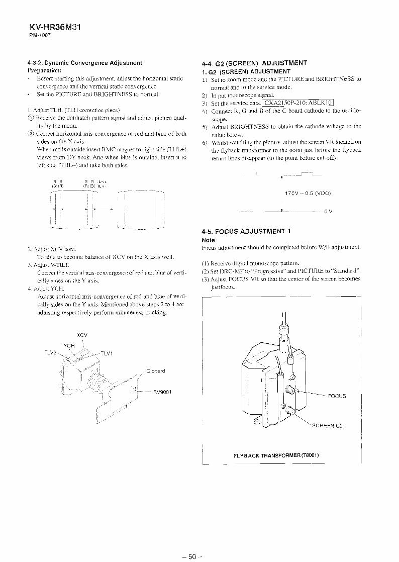
4-3-2. Dynamic Convergence Adjustment Preparation:
Before starting this adjustment. adjust the horizontal static convergence and the vemcal static convergence - Set the PICTURE and BRIGHTNESS to normal.
I . Adjust TLH. (TLH correction piece) a Receive the dotihatch pattern signal and adjust picture qual-
ity by the menu. @ Correct horizontal mis-convergence of red and blue of both
sides on the X axis. When red is outside insert HMC marnet to right side (THL+) views from DY neck. And when blue is outside, insert it to left side (THL-) and take both sides.
4-4. G2 (SCREEN) ADJUSTMENT 1 .62 (SCREEN) ADJUSTMENT 1) Set to zoom mode and the PICTURE and BRJGHTNESS to
normal and to the senlice mode. 2) in put monoscope signal. 3 ) Set the service data.~C~A3150P-210: ABLKlO 1 4j Connect R, G and B of the C board cathode to the oscillo-
scope. 5 ) Adjust BRIGHTNESS to obtain the cathode voltage to the
value below. 6) Whilst watching the picture. adjust the screen VR located on
the flyback transformer to the point just before the flyback return lines disappear (to the point before cut-off)
170V - 0 5 ( V D C )
I
L - 0 v
4-5. FOCUS ADJUSTMENT 1 Note
2. Adjust XCV core. Focus adjustment should be completed before W/B adjustment.
'To able to become balance of XCV on the X axis well. 3. Adjust V-TILT. (1 j Receive digital monoscope pattern.
Correct the vertical mis-convergence of red and blue of verti- (2) Set D R C - r n to "Progressive" and PICTURE to "Standard".
cally sides on the Y axis. (3) Adjust FOCUS LX so that the center of the screen becomes
4. Adjust YCH. justfocus. Adjust horizontal mis-convergence of red and blue of verti- cally sides on the Y axis. Mentioned above steps 2 to 3 are adjusting respectively perform minuteness tracking.
xcv YCH r I 1
1 I I
I
FLYBACK TRANSFORMER (T8001)
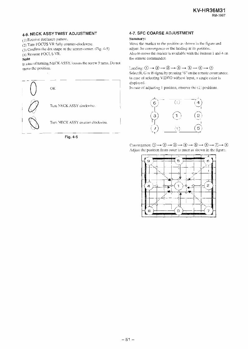
4-6. NECK ASSY TWIST ADJUSTMENT (1) Receive dot/hatch pattern. (2) Turn FOCUS VR fully counter-clockwrse. (3) C o r n the dot shape at the screen center. (Fig. 4-5) (4) Resume FOCUS VR. Note fil case of turning NECKASSY, loosen the screw 3 tulns. Do not move the position.
i ~-d Fig. 4-5
4-7. SFC COARSE ADJUSTMENT Summary: Move the marker to the position as shown in the figure and adjust the convergence or the landing at its position. Also to move the marker is available with the buttons 1 .and 4 on the remote commander.
an ding:@--+@--,@-+@--,a-+@-a Select R, G or B signal by pressing "6" on the remote conlmander. In case of selecting VIDEO without input, a single color is displayed. In case of adjusting 1 position. observe the (1) positions.
Convergence: @ 4 @ -4 @ --+ @ -+ @ --+ @ @+ @ Adjust the position from outer to inner as shown in the figurz.
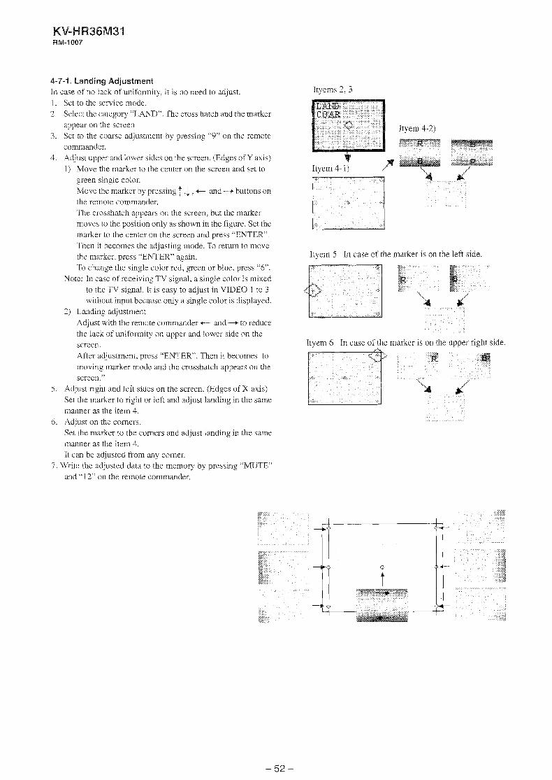
4-7-1. Landing Adjustment In case of no lack of uniformity, it is no need to adjust. 1. Set to the service mode. 2. Select the category "LAND". The cross hatch and the marker
appear on the screen 3. Set to the coarse adjustment by pressing ''9" on the remote
commander. 4. Adjust upper and lower sides on the screen. (Edges of Y axis)
1) Move the marker to the center on the screen and set LO
green single color. Move the marker by pressing 1 .l , + and -+ buttons on the remote commander. The crosshatch appears on the screen, but the marker moves to the position only as shown in the figure. Set the marker to the center on the screen and press "ENTER". Then it becomes the adjusting mode. To return to move the marker, press "EhTER" again. To change the single color red, gTeen or blue, press "6".
Xote: In case of receiving TV signal. a single color is mixed to the TV signal. It is easy to adjust in VIDEO 1 to 3 without input because only a single color is displayed.
2 ) Landing adjustment Adjust with the remote commander +- and -+ to reduce the lack of uniformity on upper and lower side on the screen. After adjustment, press "ENTER. Then it becomes to moving marker mode and the crosshatch appears on the scree~i."
5. Adjust right and left sides on the screen. (Edges of X axis) Set the marker to right or left and adjust landing in the same manner as the item 4.
6 . Adjust on the comers. Set the marker to the comers and adjust landing in the same manner as the item 4. It can be adjusted from any comer.
7. Write the adjusted data to the memory by pressing "MUTE" and "I 2" on the remote commander.
Ityems 2, 3
Itvem 4- 1)
Ityem 5 In case of the marker is on the left side.
Ityem 6 In case of the marker is on the upper right side.
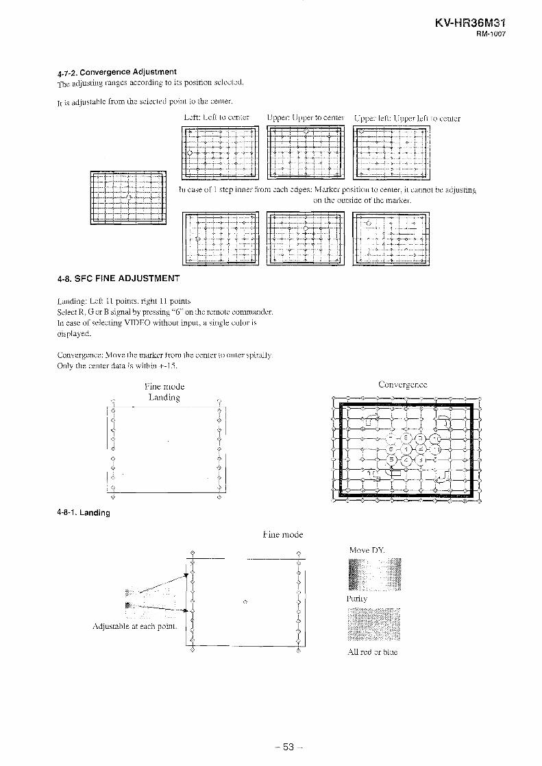
4-7-2. Convergence Adjustment 12e adjusting ranges according to its position selected.
~t is adjustable from the selected point to the center.
Left: Left to center Upper: Lpper to cenler Upper left: Upper left to center
In case of 1 step inner fiorn each edges: Marker position to center, it cannot be adjusting on the outside of the marker.
4-8. SFC FINE ADJUSTMENT
Landing: Left 11 points, right 11 points Select R, G or B signal by pressing "6" on the remote commander. In case of selecting VIDEO without input, a single color is displayed.
Convergence: Move the marker from the center to outer spirally. Only the center data is within +-15.
Fine mode
o Landing ' J
4-8-1. Landing
Fine mode
, :.
Convergence
Move DY.
Purity
All red or blue
4-8-2. Convergence
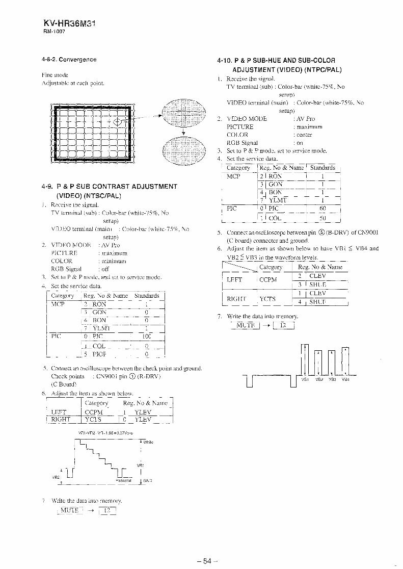
Fine mode Adjustable at each point.
4-9. P & P SUB CONTRAST ADJUSTMENT (VIDEO) (NTSC/PAL)
I . Receive the siLmal. TV termind (sub) : Color-bar (white-75%, Nu
setupj V D E O terminal (main) : Color-bar (whir-75%. Yo
setup) 2. VDEO MODE : ,2V Pro
PICTLRE : maximum COLOR : minimum RGB Signal : OR
3. Szt to P & P mode, and sei to service modc.
4. Set the service data.
5. Connect an oscilloscope between the check point and ground. Check points : CN9001 pin @ (R-DRV) (C Board)
Category
6. Adjust the item as shown below. 7 --- 1 I Category I Reg. Xo & N a m q
- . 1 LEFT C P
1 1 YLEV I 1 , RIGHr I / O YLEV ___j
-
Reg. No & Name
4-10. P & P SUB-HUE AND SUB-COLOR ADJUSTMENT (VIDEO) (NTPC/PAL)
1. Receive the signal. TV terminal (sub) : Color-bar (whte-75%, No
setup)
Standards 1 1 0 0 1
100 1
I MCp 2 I R%
5. Connect an oscilloscope between pin @ (B-DRV) of CN9001 (C board) connecter and ground.
6. Adjust the item as shown below to have VBl 5 VB4 and
VB2 5 VR? in the waveform levels.
VZDEO terminal (main) : Color-bar (while-75%. No setup)
2. V D E O MODE : AV Pro PICTURE : maximum COLOR : center RGB Signal : on
3. Set to P & P mode, set to service mode. 4. Set the senrice data.
LEFT CCPM
p a t e g o r y
I MCP
1
GO& RON YLMT
L C
1 RIGHT 1 YCTS pwz 1
3 4 7
7. Write the data into memory.
~IUTE-I +
i
7 \$'rite thz data into memory.
' Standards 1 1 - 1
Reg. No 81 Name -- 2 ( RON
0
1 60 -
, 50
3 4
PIC
GON R O N YLMT PIC
COL
I 7 PIC 0
1
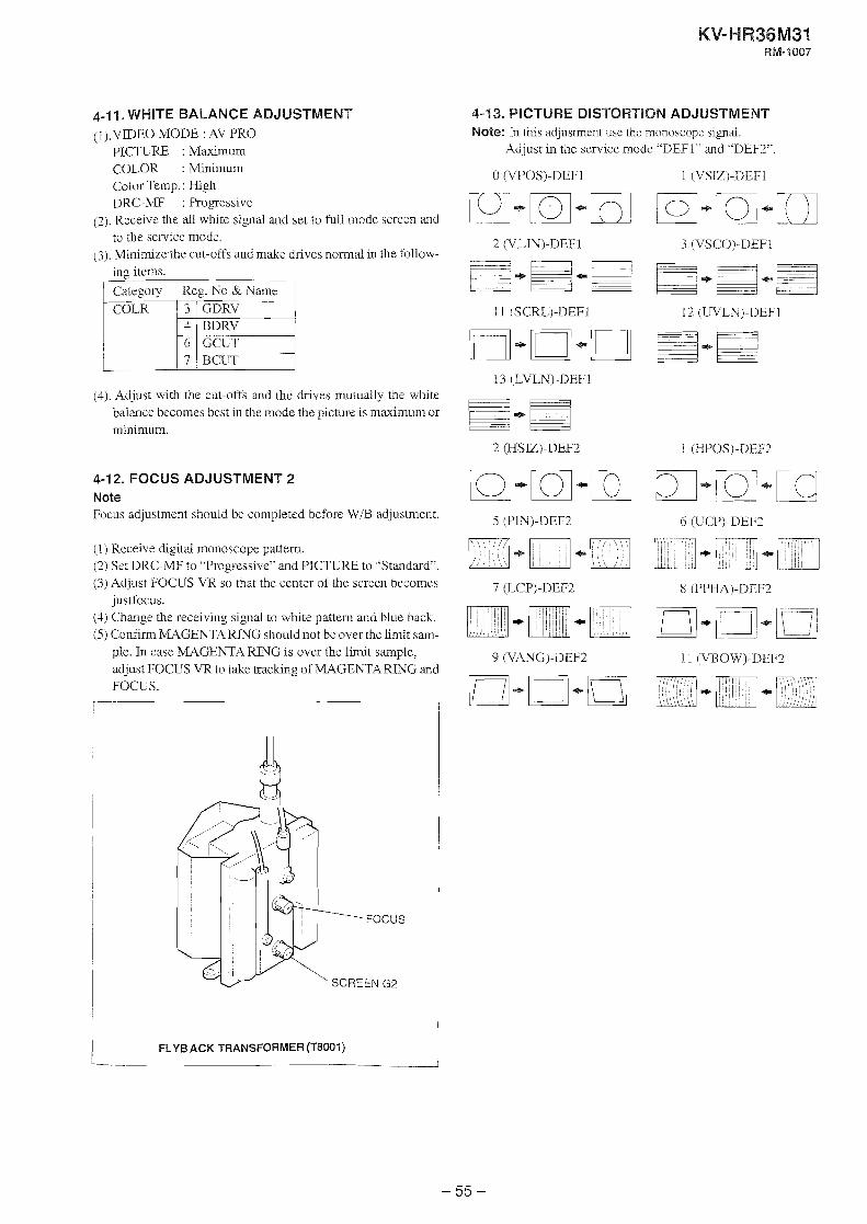
4-1 1. WHITE BALANCE ADJUSTMENT (l).VIDEO MODE : AV FRO
PICTLRE : M h n u m COLOR :Minimum Color Temp. : High DRC-MF : Progessive
(2). Receive the all white s p a 1 and set to full mode screen and to the senrice mode.
( 3 ) . Minimize the cut-offs and make drives normal in the follow- ing items.
(4). Adjust with the cut-offs and the drives mutually the white balance becomes best in the mode the picture is maximum or minimum.
4 6 7
4-12. FOCUS ADJUSTMENT 2 Note Focus adjustment should be completed before W/R adjustment.
BDRV GCCT BCCT
(1) Receive digital monoscope pattern. (2) Set DRC-YE? to "Progessive" and PICTURE to "Standard". (3) Adjust FOCUS VR so that the center of the screen becomes
justfocus. (1) Change the receivin signal to white pattern and blue back. (5 ) C o d - m MAGENTA RING should not be over the limit sam-
ple. In case Mt-\GEhTA RllVG is over the limit sample, adjust FOCUS VR to take tracking of MAGENTA RING and FOCUS.
4-13. PICTURE DISTORTION ADJUSTMENT Note: I11 this adjustment use the monoscope si_mal.
Adjust in the service mode "DEFI" and "DEF2"
FLY6 ACK TRANSFORMER (T8M)l)

SAFETY RELATED ADJUSTMENTS
[ D BOARDj 5-1. +B MAX VOLTaGE CONFIRMATION 1. Supply 242 .- ; VAC to variable autotransformer. 2. Receive dot signal pattern and set the PICTliRE and
BRIGHTNESS settings to their minimum. 7. Confirm the voltage between the both sides of C6512 on D
board is 137.0 V dc.
5-2. HV REGULATION CIRCUIT ADJUSTMENT \When replacing the following components marked with 2 on the schematic d i a ~ a m always check HV regulation, and if neces- sary re-adjust.
B: RV8002 I : lC8004, IC8005,
R8014, R8015, R8017 pH8003 T8001 (FBT) D board
1. Connect a HV static voltmeter to the unconnected plug of the high-
volta_re block.
2. Power on the set.
3. Receive the dot signal.
4. Set PIC MLV/BRT him.
5. Confirm that the static voltmeter reading is 31.5 2 0.3kVDC.
6. If not, adjust with RV8002 to the specified value.
5-3. HV PROTECTOR CIRCUIT ADJUSTMENT When replacing the following components marked with @ on the schematic diagram always check hold-down voltage and if necessary re-adjust.
El: RV8002 2: D8014
IC8001 R8016, R8019, R8046, R8052, R8072, R8078, R8079, R8165 T8001 (FBT) D board
5-4. IK PROTECTOR CIRCUIT CHECK (D BOARD) When replacing the following components marked with / on the
schematic diagram, always check IK protector circuit. : D8004
IC8001 (28007.Q8008 R8027, R8029, R8030, R803 1. R8035. R8037, R8038, R8039, R8040, R8041. R8043, D board
1. Unsolder T800 1 (FBT) Pin 1 and connect a DC current meter between Pin i and the pattern.
7 . Short circuit CYOl5. 3. Turn power on, feed the dot signal and set the picture and
brightness to minimum. 4. Feed the all white signal, increase the picture and bri~htness
slowly and check the hold-down works when the reading on the DC current meter is 2670uA.
5 . Turn power off. 6. Release C8015 short-circuit. 7. Short circuit C8012. 8. Turn power on, feed the dot signal and set the picture and
brightness to minimum. 9. Feed the dl white signal, increase the picture and brighmess
slowly and check the hold-down works when the reading on the DC current meter is 2670uA.
10. Turn power off. 11. Release C8012 short-circuit. 12. Remove the DC current meter and the external DC power
supply and solder the unsolder portions.
1. Connect a HV static voltmeter to the unconnected plug of the high
voltage block.
2. Power on the sel.
3. Receive the dot signal.
4. Set PIC MX/BRT MI&. 5. :idjust RV8002 to the 36.6kVDC reading on the static voltmeter.


![Sony kv da34m80-x80_ch_cx1_sm_[et]](https://static.documents.pub/doc/80x56/559c0a7b1a28ab896a8b469f/sony-kv-da34m80-x80chcx1smet.jpg)

![Sony Kv-29cl10k Chassis Fe2 [ET]](https://static.documents.pub/doc/80x56/54207dc27bef0ab1128b45a3/sony-kv-29cl10k-chassis-fe2-et.jpg)
