H.D.SCHULZ Engineering Process engineering and automation 5101 N Winding and laying system manual H.D.SCHULZ ENGINEERING Auf den Steinen 10, 41812 Erkelenz Germany Tel. +49 2164 4053 www.schulz-engineering.de Mail: [email protected]Fax +49 2164 49235 5101handbGBproof.doc Page 1 Electrical problem solving, measuring and control technology Drive technology, special systems, winding technology, test machinery M a n u a l Winding and laying system 5101 N-P Preliminary version software status 11/2010 Page I General specifications and features 2 II Operating methods for the field of laying with term definition 4 III Program handling 9 IV Specification of the target value for a laying station 10 V Information for edge treatment 13 Va Information for the automatic edge sensing 14 Vb Information for the automatic edge correction 17 VI Overview of function keys and menus 18 VII Manual mode 24 VIIa Automatic mode 24 VIII Menu groups for service and checking 25 IX Basic data programming of a laying station 30 X General information for installation 38 XI Optimisation information and functional test 39 XII Project planning information 40 XIII Hardware factory settings 42 XIV Functionality in conjunction with the superordinate control system 43 XV Allocation of the digital inputs and outputs 44 Safety Instructions 45 XVI Interface to master computer (optional) 46 XVII Technical data 47 Annex I Program for archiving the 5101 N system program memory 49 XVIII Schematics 51 Attention: For control of the core rotation see "Core control manual" For Profibus see "Profibus manual"
Electrical problem solving, measuring and control technology Drive technology, special systems, winding technology, test machinery
M a n u a l
Winding and laying system 5101 N-P
Preliminary version software status 11/2010
Page
I General specifications and features 2 II Operating methods for the field of laying with term definition 4 III Program handling 9 IV Specification of the target value for a laying station 10 V Information for edge treatment 13 Va Information for the automatic edge sensing 14 Vb Information for the automatic edge correction 17 VI Overview of function keys and menus 18 VII Manual mode 24 VIIa Automatic mode 24 VIII Menu groups for service and checking 25 IX Basic data programming of a laying station 30 X General information for installation 38 XI Optimisation information and functional test 39 XII Project planning information 40 XIII Hardware factory settings 42 XIV Functionality in conjunction with the superordinate control system 43 XV Allocation of the digital inputs and outputs 44 Safety Instructions 45 XVI Interface to master computer (optional) 46 XVII Technical data 47
Annex I Program for archiving the 5101 N system program memory 49
XVIII Schematics 51 Attention: For control of the core rotation see "Core control manual"
Electrical problem solving, measuring and control technology Drive technology, special systems, winding technology, test machinery
Operation via graphic terminal see "5101 graphic" manual
I General specifications and features The 5101 N laying and winding system contains the highly successful laying computer 2603 N as its basis. The terminal configuration of the basic device is compatible with the 2603 N system, but with a significantly extended scope of functions. All of the functions of a winding system with laying, winding tension or dancer roller as well as control of the dispensing reel are available with the fully equipped version with options circuit board.
Area of application: - Creation of a defined winding pattern through control of a laying support. - Control of the winding speed through ramps with compensation for material speed, or - Control of the winding tension with integrated winding computer or dancer control with
master value presetting - Control of the dispensing reel - Equipping for individual applications, as well as for machines up to 48 laying stations
linked via network, operable via a common Miniterminal. - For all winding tasks with flat and round material, laying width up to 3200mm, loading
position separated up to 9m. Gate winding mode with missing synchronised traction - Use of different winding components with straight and conical side parts as well as
without side parts
Important characteristics in keywords: - The equipment stands out through simple handling, minimal installation workload and though its universal
applicability. - Entry of all parameters with operator assistance in physical values e.g. winding core data, material width, material
gap, material diameter as well as all edge parameters in millimetres. All speed and tensioning parameters in percent. - Convenient operation with backlit 2 x 40 character alphanumeric text. With 19 function buttons labelled in simple
text (some of which can be saved in multiple languages), as well as a numeric keyboard. - Sturdy covered keyboard with high degree of protection. - Convenient program management with the transfer of the programs to several laying stations at the command of
the operator. - Storage capability - up to 200 programs - Extensive diagnostics functions with plain text display - Network up to 48 winding systems to one control panel - Additional interface for control technology as an option - Profibus coupling
Electrical problem solving, measuring and control technology Drive technology, special systems, winding technology, test machinery
Material laying - Convenient programming of all material and edge data in mm - Automatic target angle calculation for the edge area as well as target angle presetting,
target angle requirements as well as measurement and presetting in degrees. - Comprehensive parameterisation capabilities for the edge area (likewise with operator
assistance) - Automatic edge correction without additional sensor systems with associated material, for
preventing an edge recess or ridge. - Entry angle tracking sensor-controlled, with layer winding - Input options for edge increment or edge decrement for winding on winding forms with
conical edge boundaries - Automatic edge sensing of the winding form for optical or mechanical systems - Preselection of layer count - In semi-automatic learning mode the physical adaptation to almost every support solution is
possible. - Various manual functions as well as automatic reference point run
Winding on
(The functions listed below can be selected as options)
- Control of the core speed through ramps, parameter selectable as input value by operator or as external analogue value
- Stipulation of the material flow speed selectable as input value by operator or as external analogue value
- Tension control with integrated winding computer, parameter selectable as input value by operator or as external analogue value
- Integrated dancer control operating on the winding drive with master value detection
Master drive - Control of the master drive through ramps, parameter
selectable as input value by operator or as external analogue value
Winding off
- Target value specification for the winding off drive, dancer or tension
controlled
Overall functional characteristics - Automatic offset compensation of the laying position control circuit - Various machinery control functions via galvanically separated inputs and outputs - Small physical form, with integrated mains adapter for standard rail-mount within a control cabinet.
Electrical problem solving, measuring and control technology Drive technology, special systems, winding technology, test machinery
- Control unit separated by a 6-core cable (incl. power supply)
II Operating methods for the field of material laying with term definition Network With the help of the network up to 48 laying stations can be programmed and monitored with a Miniterminal. At any time the desired laying station can be selected via the Miniterminal. After selection all Miniterminal functions relate to the selected laying station. Reference point run After the system has been commissioned (switching on the power supply) a support reference point run is required first of all. This function can be selected from the basic data menu whenever required. Locating the correct position after switch-on is then no longer guaranteed if the support has been moved when unpowered. The reference point run works as follows: With the command AUTOMATIC the support drives to the left to the MIN position, until it reaches the reference point limit switch. Then the drive reverses and stops on the first zero pulse from the incremental encoder after leaving the reference point limit switch. Target point run Target point run means the drive to a preset programmed position. Two independent positions can be programmed in this system: The first position is entered as an offset of the material to the edge (right or left can be selected) and is thereafter designated Start position. The material width will be automatically taken into account with this. The start position will change with the changing of the edge. The second position is entered as an absolute position. This can thus also lie outside the edges of the winding. The second position is often used as unloading position. A target point run generally causes a new start with empty winding core and with a resetting of the layer counter. The target point run is initiated through the simultaneous commands Automatic and Drive to start position. These commands must remain active until the target position has been reached. The target point run is implemented with an acceleration ramp, a defined max. speed and a logarithmical braking ramp until the target point is reached. The target point is held in the position control circuit. All parameters can be adjusted in the background menu or within the program. If enabled in the basic data menu there is an automatic offset calibration for the target point if the signals AUTOMATIC and Drive to start position have been present for some time. An offset calibration at the servo controller is thus generally not required. A target point run is fundamentally required after a reference point run!
Electrical problem solving, measuring and control technology Drive technology, special systems, winding technology, test machinery
The laying operation after the target point run is only possible if the target point lies within the laying edges. (must only be observed with 2 positions) Laying operation As soon as the "Automatic" command is present the system is permanently in laying mode. At the same time there is a rigid connection existing, with the help of a high resolution digital shaft, between the position of the core and the position of the laying support. This rigid connection also exists, without any limitations, in reverse direction (reverse drive of the winding core). Laying operation is only possible if the support is located within the programmed edges. Control system in normal operation The laying support occurs with a dragging action by means of a digital shaft. The size of the dragging offset is compensated for depending on the speed. Overriding this is an adjustable mechanism for limiting the change in speed. The aforementioned process enables a reversing at the edges which helps preserve the machinery. From this clearly a lower amplification factor should be used in laying operations with slower movement of the laying support during operation as well as with larger masses. The resultant positional deviation can be fully compensated for. A smaller amplification factor leads to a smoother running in to the limit positions. Edge correction (edge treatment) In order to stabilise the winding in the edge areas when approaching the edge as well as when moving away from the edge, it is possible to preset an edge acceleration for each individually which behaves in a capacity-neutral manner with regards to a complete laying cycle. This acceleration reduces automatically with increasing core diameter with the corresponding preset value. The presetting of an edge acceleration leads automatically to a corresponding edge stop. An additional edge increase or edge reduction is possible through entering an additional positive or negative edge stop. Skew angle calculation The skew angle is the angle between two reversing points on the edge when viewed axially after a laying cycle (one pass forward and back). The skew angle is calculated and displayed after the material width or gap is entered. This angle is displayed in degrees. After stipulating a target angle there is an automatic re-calculation of the material gap (added to the target gap) with the goal of a controlled angular displacement. The edge acceleration, edge increment, edge stop etc. are also all incorporated into this calculation. Alteration of the target values for material width or material gap will result in the automatic deletion of the target angle entered, because the target value for the material gap has priority in this moment. The alteration of the left or right winding edge as well as the alteration of the edge stop likewise results in the target angle value being overwritten, insofar as a zero has been entered in the basic data menu under G27. If a 1 is entered in the G27 basic data menu then an alteration of the winding edges as well as the edge stop results in the target angle value being preset anew in accordance with the original target angle value entered under the alteration of the material gap. The material gap calculated by the computer can be called up in the S1 menu group.
Electrical problem solving, measuring and control technology Drive technology, special systems, winding technology, test machinery
Consideration of conical winding edges An alteration of the laying width can be entered - either increasing or decreasing. The presetting of a skew angle is also possible with this operating mode. The material gap, added to the target gap, is correspondingly altered automatically from layer to layer. Edge offset An edge offset can be programmed individually for every laying station. This can be entered as a positive or negative and both edges are moved equally. The start position and the second position are also moved accordingly with this. Through this function it is possible, independent of a collective program preset for several laying stations, to implement an individual adaptation for individual laying stations. This edge offset is not a constituent part of a storable program and remains even after changing programs.
Electrical problem solving, measuring and control technology Drive technology, special systems, winding technology, test machinery
Material feed line This line forms the mechanically fixed reference point in the material feed. This line remains stationary when the material width changes. If this line is in the middle of the material then the core data need not be newly defined when the material width changes. Alternatively when using automatic edge sensing either the left or the right material edge can be defined for this.
Edge sensing This sensing serves to measure the edges of the winding form (winding edge not conical) precisely. By default the system requires the middle of the material as mechanical fix-position. The selection of the left or right material edge as fix-position is likewise possible. (See material feed line) Two methods of edge sensing for the empty winding form are supported by the computer. Optical sensing: Detection of the edges through a light barrier arranged perpendicularly to the winding axis. The position of the winding edges must only be entered with an accuracy programmed under D4. After the appropriate command the left and right inner edges are sensed automatically one after the other in conjunction with a core rotation. Mechanical sensing (internal sensing): Detection of the inner edges through a manual mechanical probe pivoting between the edges. This middle position can be approached automatically with the help of the second programmable target position. The release for the sensing must be issued separately for the left and right by the superordinate controller. The automatic detection of a lateral run-out is not provided - if required this must be effected by the superordinate controller. The customer must provide suitable means of protection from mechanical damage for the measuring probe as well as the complete system in the event of a malfunction of the computer.
Electrical problem solving, measuring and control technology Drive technology, special systems, winding technology, test machinery
Automatic edge correction
a. Without sensors In order to prevent the formation of a recess of ridge in the edge area the enabling of an automatic edge correction is possible for non-layered wound material. This feature is available for cylindrical and conical winding forms. With conical winding forms the edge area in question is calculated taking the increase or decrease in diameter into account. Ridges and recesses at the edge are detected and compensated for through edge data adjustment via highly accurate diameter sensing by our system (which also works in dynamic operation). A special 2-channel control system guarantees optimum results. In conjunction with the automatic edge sensing of the winding core, fully automatic operation with changing core geometry is also possible with this.
b. Sensor controlled
In order to check the material entry angle with material wound in layers, (gap = 0) a corresponding sensor signal is evaluated by our system and the angle is constantly corrected in accordance with a special calculation rule.
Special function, disc winding:
By programming the same value for the left and right edge, the support will be kept at the programmed position by the position control circuit after target position run. The layer counter works as winding counter with contact output after completion.
Connection to master computer (optional) By means of the two interfaces at terminal 2780 it is possible to transfer programs from the master 2780 to the laying stations through a command from a superordinate control station Further options with regards to the interface are in work!
Electrical problem solving, measuring and control technology Drive technology, special systems, winding technology, test machinery
III Program handling The following are explained below: -1 Transfer of a program from a laying
station to the Miniterminal as a memory This function can be protected with a passcode if selected. The desired passcode is entered into the basic data. Entering 0 means that there is no passcode protection. Without the correct passcode menu no. 1 is bypassed.
-2 Transfer of a program from Miniterminal
to one or more laying stations If a passcode is activated then the entry of the passcode 1 2 3 4 leads directly to menu no. 2
All of the operations described below are to be confirmed with ENTER. -1: Actuate the B button and enter the 4-digit passcode The menu B1 enables the program transfer from an arbitrary laying station to the Miniterminal (Master). The program can be saved under an arbitrary program number (new number) in the Miniterminal. In addition the menu also shows the program number under which the program was originally stored in the laying station. -2: After changing menu menu B2 enables the transfer of an arbitrary program from the Miniterminal (Master) to one or more laying stations. In the event that only 1 laying station (UNIT) is addressed then the same laying station should be entered in response to the question TO WHICH UNIT? The procedure can be repeated after pressing the button. Thus it is possible to allocate programs to any number of groups of laying stations in a short time. Attention! The transfer of programs to the laying stations is not permitted during automatic laying operation. That means that the corresponding laying stations must be switched to manual.
Electrical problem solving, measuring and control technology Drive technology, special systems, winding technology, test machinery
IV Specification of the target value for a laying station It is advisable that the laying station to be programmed be ready for operation and have already completed a reference point run. After actuating the A button, select the desired laying station. The currently active function as well as the program number presently installed at this laying station are shown in this menu.
All of the target value inputs described below directly affect the program in the winding station. Any program stored in the Miniterminal under the same program number is not affected by this.
That means that after creating and testing the program, this must be transferred from the laying station to the Miniterminal (Master) for the purpose of archiving it. Material-related data After actuating the C button the following data can be entered in the C1 menu: - Material width - Material gap - Core growth rate (acceleration reduction) - Skew angle After an alteration of the material width and/or material gap the resultant skew angle is automatically displayed. However, the skew angle resulting from the consideration of the stipulated gap can be overwritten whereby the system alters the gap accordingly. The actual gap can be called up in the C2 menu. After changing menu under C2 : - Number of layers desired - Edge stop - Skew angle are entered. The actual gap is shown for information. After changing menu in the C3 menu: - The edge area when approaching the edge - The acceleration when approaching the edge - The edge area when leaving the edge - The acceleration when leaving the edge are entered.
Electrical problem solving, measuring and control technology Drive technology, special systems, winding technology, test machinery
Core-related data After actuating the D button the following entries are offered in the D1 menu: - Left edge - Right edge - Start position as offset from left edge or right edge (basic data setting) - Start direction (0 forwards, 1 backwards)
The left and right edge can also be entered in the teach in process after setting up the reel in manual mode. For this bring the support to the desired position by hand and then set the cursor in the Miniterminal to the point Left or right edge.
The position value can be adopted with the help of the teach in button and Enter. The material width is automatically taken into account with this. With corresponding presetting the left or right edge can be changed during automatic operation with the help of the terminal buttons forward / back. The cursor must be set at the corresponding value for this.
After changing menu the following are to be entered under the D2 menu: - Core diameter (only relevant if an automatic reduction in acceleration is desired) - Adjust pre-contact as offset from edge, if desired - Positive or negative edge increment for conical winding edges - Positive or negative edge offset for all core data to compensate for mechanical differences between the individual
winding stations
The edge offset programmed here is fundamentally allocated to the corresponding laying station and is not a constituent part of the program to be saved.
After changing menu the following are to be entered under the D3 menu: - Start position 2 (unloading position) - Reducing the edge acceleration with increasing core diameter -> 1, otherwise -> 0 -------------------------------------------------------------------------------------------------------------------------- Attention:
The following menu is only available after the automatic edge sensing is enabled. (Basic setting)
After changing menu the following are to be entered under the D4 menu: - Hysteresis of the edge sensing (search field with automatic edge sensing)
Electrical problem solving, measuring and control technology Drive technology, special systems, winding technology, test machinery
Attention: The following menus are only available after the automatic edge correction is enabled. (Basic setting)
After changing menu the following are to be entered under the D5 menu: - Measurement delay after reaching the edge (number of core revolutions) - Size of the measurement field at the edge (number of core revolutions per minute = 1) - Position of the comparative measurement (offset from edge in mm) - Size of the measurement field at the comparison (number of core revolutions per minute = 1)
After changing menu the following are to be entered under the D6 menu: - Size of the correction (edge correction) - Number of paused layers without corrective action - Desired diameter banking or reduction on left edge (in mm) - Desired diameter banking or reduction on right edge (in mm)
Electrical problem solving, measuring and control technology Drive technology, special systems, winding technology, test machinery
V Information for edge treatment
The following parameters are available for optimising the edge: - Presetting of the skew angle - Edge acceleration - Edge stop - Edge increment Skew angle
The desired skew angle is to be entered in the C1 or C2 menu (see term definition for detailed explanation).
Edge acceleration
An edge acceleration when approaching and/or leaving the edge can be programmed (menu C3). The input comprises the value of the edge area in mm in which this acceleration is to be effective and a value for the acceleration. The permissible input value for the acceleration is 0-128. 0 No acceleration 32 2 times acceleration 64 4 times acceleration etc. Application as follows: Within the edge area the support is accelerated by the value specified. The resultant advance in travel is compensated for by a corresponding pause at the edge. Thus the function does not alter the skew ankle. Values between 8 and 32 are recommended for the acceleration. The value for the edge area should be approx. 1.5 x the material width. The value for the edge acceleration will be reduced with increasing core diameter if the corresponding parameter is enabled in the D3 menu. The size of the increase is controlled with the help of the core growth rate in menu C1. If the default position should lie within the edge area after target point run then the edge acceleration will only be activated upon leaving the edge.
Electrical problem solving, measuring and control technology Drive technology, special systems, winding technology, test machinery
Edge stop
An additional edge stop (menu C2) is given in millimetres and is related to an intended increase in the laying width, whereby a waiting time for the support will be initiated upon reaching the edge. This value can be entered as a positive or negative value. With a negative value any edge waiting time initiated through the edge acceleration will be shortened. A positive value means a material increase at the edge, a negative value means a reduction in material.
Edge increment
Creation of conical winding (conical winding edges), either increasing or decreasing, through an increase or decrease of laying width for each layer. Entry of a positive or negative value in mm. A preset skew angle for the reversing point is also retained with this type of laying. The material gap changes correspondingly from layer to layer. With a 45 degree conical winding form the following rule of thumb can be applied. With flat material (layer-wound): 2 times material thickness = Edge increment With round material: Material diameter times material diameter times 1.8 divided by material gap
Va Information for the automatic edge sensing There are two processes provided for automatic edge sensing. - Optical sensing by means of a light barrier - Touch-based sensing with a mechanical measurement probe or similar
Generally the optical sensing is the preferred method because this: - has a shorter sensing time and - takes the side stops of the winding form into account
Additionally, there is no risk of mechanical damage to the measuring system.
Electrical problem solving, measuring and control technology Drive technology, special systems, winding technology, test machinery
Optical sensing
A calibration of the measurement systems is to be carried out in the basic data menu under G29 for the Offset of material feed to measurement probe G30 for the Diameter of the light beam G31 for the Creep speed of the sensing G29 and G30 can be entered as positive or negative. For explanation of Material feed see under general description
Functional flow of the sensing is as follows:
After the start command the left edge that was previously manually entered less the hysteresis entered under D4 is approached at target run speed. After reaching this position the light barrier must be interrupted. Then the support moves in creep speed until the light beam is unbroken again. Now the subsequent core rotation checks the winding form for any possible side stop. If the light beam should be interrupted during the core rotation then the core rotation will stop and the light beam will then be driven free again. After the start core rotation is completed the right edge less the hysteresis entered under D4 is approached at target run speed. After reaching this position the light barrier must be interrupted. Further functions as described for the left edge. After the core rotation is completed the sensing is ended. The support remains in its current position. Generally, after this a target point run should be implemented in the start position.
Application of this edge sensing:
Automatic entry of the values for the left and right edge in the laying station. Attention should be paid to the following:
- Approximate values for the left and right edge must be entered manually or entered with teach-in beforehand. - The deviation must not exceed the value entered under D4 for the hysteresis. - If the material feed line does not correspond with the centre of the material then the values must be defined anew with each change in material width.
Electrical problem solving, measuring and control technology Drive technology, special systems, winding technology, test machinery
Mechanical sensing
A calibration of the measurement system is to be carried out in the basic data menu under G29 for the Offset of material feed to measurement probe G30 for the Diameter of the measurement probe G31 for the Creep speed of the sensing
G29 can be entered as positive or negative.
For explanation of Material feed see under general description Functional flow of the sensing is as follows:
To begin with the support must be manually (or with the help of the second target position programmed in the menu D3) driven to a position in which it is possible to manually pivot the measurement probe free from the left and right edges. After pivoting the measurement probe the following commands must be given by the superordinate control system (next command after each completion signal): - Sense left - Sense right It is possible to drive to the second target position between the two commands in order to save time. These sensing commands result in the following:
- Support drives with 4 times creep speed until it touches the measurement probe - Support reverses and drives with creep speed until free of the measurement probe again - In each instance the edge position detected is saved taking all of the calculation parameters into
account.
In order to avoid mechanical damage in the event of a malfunction the measurement probe must be equipped with an additional stop function which acts on the support when large pivoting actions occur ! See also information on commissioning!
Electrical problem solving, measuring and control technology Drive technology, special systems, winding technology, test machinery
Vb Information for the automatic edge correction
a. Without sensors In order to prevent the formation of a recess or ridge in the edge area the enabling of an automatic edge correction is possible for non-layered wound material. This feature is available for cylindrical and conical winding forms. With conical winding forms the edge area in question is calculated taking the increase or decrease in diameter into account. Parameter input occurs after being enabled in the setup menu in menu groups D4 and D5 . Monitoring of the working process is possible through menus S12 - S14. Working process: Automatic calculation of the respective target diameter at the edge. (Also with conical
winding forms) Compensation of the current status through edge alteration.
b. Sensor controlled
In order to check the material entry angle with material wound in layers, (gap = 0) a corresponding sensor signal is evaluated by our system and the angle is constantly corrected in accordance with a special calculation rule. Parameter input under D8 after enabling and parameterisation in the setup menu.
Electrical problem solving, measuring and control technology Drive technology, special systems, winding technology, test machinery
VI Overview of function keys and menus A menu group is selected by means of the associated function key. Within the menu group it is possible to scroll between individual menus with the help of the keys. It is possible to jump between the entries within a menu with the keys. Each new entry or each overwriting of an entry is completed with Enter . For certain entries it is possible to accept the current value in Teach-In
Explanation of the individual menus Menu group for monitoring and selection of the laying stations A1 Selection of the laying station 1-48
Display of the program currently running at this laying station, as well as status messages for the laying station and fault messages if present. The following status messages are possible: AUTOMATIC Automatic mode TARGET RUN Support is located on the way to the default position or in the default position REF.P.RUN Support is on the way to reference point REF:P:MISSING Operation not possible as reference point is missing MAN.FWD MAN.BACK E-SENSING ACTIVE Edge sensing in progress
The following alarm messages are possible: ALM SENSOR CORE The position sensor for the core rotation is malfunctioning ALM LAYING SENSOR The position sensor for the support is malfunctioning ALM PROGRAM The program assigned to the laying station cannot be
implemented. ALM LIMIT POSITION A limit position has been reached in automatic mode (with associated enabling). ALM MOTOR The support cannot obey the control commands of the computer ALM EDGE SENSING Edge sensing cannot be implemented EXTERNAL ALARM There is an alarm present at a laying station that is presently not selected.
After changing menu to A2 the laying station which triggered the alarm is displayed.
Delete the alarm message by resetting the digital alarm output:
Electrical problem solving, measuring and control technology Drive technology, special systems, winding technology, test machinery
Before program alteration functions or monitoring functions are possible for a laying station these must first be selected with A MAIN. Program handling
Program transfer functions from an arbitrary laying station to the Master (control panel) or from the Master to an arbitrary laying station or a group of laying stations. After selecting this menu group the Passcode 1 2 3 4, should be entered. If passcode protection exists then this should be entered. Without the associated authorisation only the B2 menu group is accessible.
B1 FROM UNIT ? PROG.NO. ? TO MASTER PROG.NO. ?
Transfer of the program from an arbitrary laying station to the Master and saving under an arbitrary program number (1-200). The program number that is currently active in the laying station is displayed. For the Master the same program number is suggested - however, this can be arbitrarily overwritten.
B2 PROG.NO. ? TO UNIT ? UP TO ? FINISHED!
A program saved in the Master can be simultaneously transferred to one or more laying stations with this command. The laying station entered must be physically present and ready for operation.
Electrical problem solving, measuring and control technology Drive technology, special systems, winding technology, test machinery
Entry of material-relevant data (With corresponding default settings, only possible after authorisation after input of the passcode, otherwise data can only be viewed).
C1 MAT.WIDTH ? MAT.GAP ? CORE-GR. ? SK.ANGLE ?
Mat. width Material width Mat.gap Material gap Core-Gr. Core growth rate per layer for the acceleration reduction See keyword Acceleration reduction, Sk.Angle Skew angle
(See also under keywords) After entering the material width or material gap the current value, which results from taking the gap target value into account, is shown here. This value can be overwritten with the desired angle, whereby the gap when added to the target gap changes accordingly.
C2 LAY-PRESEL ? EDGE-ST ? ACT.GAP ! SK.ANGLE ?
Lay-Presel Preselecting of the desired winding layer or length (meter counter) The internal counter is set to the preselected layer with the Drive to default position command. After reaching the corresponding layer count a signal is output to the superordinate control system. The selection of winding layer or length is implemented in the basic data menu GL1, the text changed correspondingly.
Edge-St Edge stop
Entry in millimetres for the imaginary edge growth. This value can be entered as a positive or negative value, see keyword Edge stop
Act.Gap Display of the actual material gap This is given from the selection of a skew angle Sk.Angle Display or preselection of the skew angle Identical to menu C1
C3 E-AREA-A ? ACCEL-A ? E-AREA-L ? ACCEL-L ?
E-Area-A Edge area for the acceleration when approaching the edge See keyword. Accel-A Acceleration within the edge area when approaching See keyword E-Area-L Edge area for the acceleration when leaving the edge Accel-L Acceleration within the edge area when leaving the edge
Electrical problem solving, measuring and control technology Drive technology, special systems, winding technology, test machinery
Entry of the core data D1 L-EDGE ? R-EDGE ? ST-POS ? ST-DIR ?
L-Edge Left edge Only positive values are physically possible and allowed R-Edge Right edge Only positive values are physically possible and allowed. ST-Pos Start position as offset from left edge This position is driven to upon the external command drive to start position being given. ST-Dir Presetting of the start direction after driving to the default position
Input 0 represents forwards, input 1 represents backwards. This entry is only relevant if a start position greater than 0 is entered.
D2 CORE-DIA ? PRECON ? E-INCR ? E-OFFSET ?
Core-Dia Diameter of the empty winding core
An entry greater than 0 implements the program algorithm Acceleration reduction (see keyword)
PreCon Position of the pre-contact
in mm. Offset to the winding edges. Only works correctly with positive core rotation.
E-Incr Positive or negative edge increment per winding layer. Conical reels can be wound with the help of this function. (See keyword) R-Offset Edge offset for both edges
(See keyword) With the help of this function the support axle can be displaced positively or negatively by a correction value. This function is not a constituent part of the program but rather is assigned to the corresponding laying station. This value therefore remains even after the transfer of a new program to the laying station.
Electrical problem solving, measuring and control technology Drive technology, special systems, winding technology, test machinery
D3 ST-POS2 ? LAY.W.GAP ? A-RED->1 ? M-TEN
St-Pos2 Second start position Target or unloading position Lay.w.Gap Number of winding layers without gap after driving to the start position (0) A-Red 1= Acceleration reduction with core growth, M-TEN Target tension output as analogue value on channel 1, adaptation via G23 possible
The following menu groups are accessible individually or together only in accordance with corresponding basic settings. With automatic edge sensing D4 E-HYST ?
E-Hyst Edge covering with automatic edge sensing Only positive allowed (see edge sensing)
With automatic edge correction , without sensors D5 W-START ? W-M-FIELD ? COMP ? W-COMP ?
W-start Offset measurement window after edge reversal
In core rotation - Input 0 to 20 (1) W-M-Field Size of the measurement window In core rotation - Input 1 to 30 (3) Comp Offset of the comparison window to the edge in mm W-Comp Size of the comparison window In core rotation - Input 1 to 50 (10)
D6 DISPL ? PAUSE ? CORR-L ? CORR-R ?
Displ Scale of the edge correction
1 to 5000 (400) Pause Pause for the implementation of the correction Number of layers 0 to 20 (0) Corr-l Edge lifting, left edge in mm Corr_r Edge lifting, right edge in mm
Electrical problem solving, measuring and control technology Drive technology, special systems, winding technology, test machinery
With automatic edge correction , with sensors D8 EA BCK ? EA FWD ? ENTRY ANGLE DISPL. ?
Ea bck. Material entry angle target value direction min (0) Ea fwd Material entry angle target value direction max (0) Entry angle displ. Size of the correction per core rotation (32)
Target angle entered as positive value for advancing and negative value for lagging. The scale of the value depends upon the resolution of the sensor. Maximum values are: +/- 255
Electrical problem solving, measuring and control technology Drive technology, special systems, winding technology, test machinery
VII Manual operation If the command Automatic is not present at the digital input of the laying computer then the corresponding laying station is in manual mode. Depending on what has been enabled in the basic data, the support is controlled via 2 digital inputs, or via the manual control level in the terminal, with a speed that is set in the basic data screen. When controlled via the terminal the digital inputs are used for end position limiting. (No safety function) Selection of the corresponding laying station is necessary for control via the terminal. In addition a limit position shut-off should be implemented externally via the servo system. This manual control does not represent any safety control in the sense of the accident prevention regulations. Access to the hazardous area requires a complete enabling of the servo system or the activation of similar safety devices.
VII a Automatic operation The first time the Automatic command is present at the digital input after the power is reinstated, a support reference run is implemented. Then it is necessary to drive to the start position by means of the appropriate command. After reaching the start position the system is in laying operation. In order to enable laying operation the support must be located within the programmed laying edges. This must be taken into account after a manual displacement of the support.
Electrical problem solving, measuring and control technology Drive technology, special systems, winding technology, test machinery
VIII Menu groups for service and checking S1-S3 The display of various important data and functions is possible by means of these menu groups. The corresponding laying station must be selected beforehand via the A-MAIN menu. The inputting of data is not possible within these menus. Service 1 Position Position of the support Gap Actual implemented material gap A-> Current acceleration when approaching the edge Core Radius of the winding core, taking the core growth rate into account (Only active with corresponding presetting) Layer Remaining number of winding layers before reporting A<- Current acceleration when leaving the edge The following service menus S12 to S14 are only visible when sensor-less edge correction is activated. Service 12 Core-d Current core diameter Physically comparable (GS1) Action The presently active function with regard to the correction calculations
10 Start of the 1st comparison measurement for the left edge 11 End of the 1st comparison measurement for the left edge 12 Start of the 2nd comparison measurement for the left edge 13 End of the 2nd comparison measurement for the left edge 14 Pause between edge and left measurement field 15 Start of the measurement field at the left edge 16 End of the measurement field at the left edge 20 Start of the 1st comparison measurement for the right edge 21 End of the 1st comparison measurement for the right edge 22 Start of the 2nd comparison measurement for the right edge 23 End of the 2nd comparison measurement for the right edge 24 Pause between edge and right measurement field 25 Start of the measurement field at the right edge 26 End of the measurement field at the right edge
Corr-L Current edge alteration for the purpose of left correction in mm Corr-R Current edge alteration for the purpose of right correction
Electrical problem solving, measuring and control technology Drive technology, special systems, winding technology, test machinery
Service 13 Target_l Target diameter of the core at the left edge Interpolated from the comparison window
Physically comparable (GS1) Current_l Current diameter of the core at the left edge Target_r Target diameter of the core at the right edge Interpolated from the comparison window
Physically comparable (GS1) Current_r Current diameter of the core at the right edge Service 14 Ref-l1 Diameter at the 1st comparison window for the left side
Ref-l2 Diameter at the 2nd comparison window for the left side
Ref-r1 Diameter at the 1st comparison window for the right side
Ref-r2 Diameter at the 2nd comparison window for the right side
Electrical problem solving, measuring and control technology Drive technology, special systems, winding technology, test machinery
The following service menu S17 is only visible when sensor edge correction is activated. Service 17 Ea-target Wire entry angle target value Resolution +/- 255 per analogue sensor parameters
Ea-Current Wire entry angle current value Resolution +/- 255 per analogue sensor parameters Corr Correction value with regards to support movement per core rotation No physical allocation
Electrical problem solving, measuring and control technology Drive technology, special systems, winding technology, test machinery
Service 2 Inc.Core Counter status, core incremental encoder, Target position for the zero point checking, Current position for the zero point checking, Number of faults during zero point checking Inc.Lay Counter status, laying support incremental encoder, Target position for the zero point checking, Current position for the zero point checking, Number of faults during zero point checking
This data is intended for service purposes and serves to assist fault identification within the position sensing system. Target and current values for the zero point may differ by up to 16. With a large difference the counter error is corrected by an intelligent correction algorithm. If this seems to be no longer possible then a Sensor alarm is triggered within the main menu with a corresponding digital output. (See also keyword) Every corrective measure will be counted by the fault counter. This enables the assessment of the sensor condition and the disturbances. The zero pulse checking of the core is not active in the standard version.
Delete the counter as follows: Menu A selection, with selection of the laying station Cursor right, enter "99" and Enter Service 22 Display only with activated options board I-Cond Counter status, master value incremental encoder, Sensor for measuring the material feed Speed Speed of the material feed Computational raw value without physical adaptation A-in 1-4 Analogue values 1 to 4 (Display only with sensor or core control) 0 – 255 -> 0 to 10 Volt
Electrical problem solving, measuring and control technology Drive technology, special systems, winding technology, test machinery
Service 3 In Display of the currently activated digital inputs at the laying station Out Display of the currently activated digital outputs at the laying station A-Out Value of the analogue output at the servo regulator for the support +/-10 V corresponds to +/- 2000 Offset Residual offset of the support In the default position after automatic offset compensation
Service 32 Display only with activated options board In2 Display of the currently activated digital inputs at the options board Out2 Display of the currently activated digital outputs at the options board A-Out3 Value of the analogue output at output 3 (core rotation target value). See manual Winding +/-10 V corresponds to +/- 2000 A-Out4 Value of the analogue output at output 4 (miscellaneous). See manual Winding +/-10 V corresponds to +/- 2000
Electrical problem solving, measuring and control technology Drive technology, special systems, winding technology, test machinery
IX Programming basic data for a laying station The following pages are to be removed from the manual after commissioning as these setup instructions also contain the passcodes required and these should only be accessible to the servicing and commissioning personnel. The values in () represent a suggestion for the initial commissioning and must be adapted accordingly. The input options are the following:
- Number of laying stations in the system - Addressing a laying station - Transfer of basic data from a laying station to the Master - Transfer of the basic data from the Master to one or more laying stations
GHD Passcode 2780 GH29 MAX INTERFACE NO. IN SYSTEM ? Stipulation of the highest laying station number in the system All laying stations are to be named in an increasing sequence starting with 1 (see addressing). It is not permitted to miss out numbers. GH30 NO.OF CONNECTED DEVICES ? Addressing a laying station In order to assign an address number (1-48) to a laying station all laying stations must be disconnected from the network with the exception of the one that is to be addressed. After entering the desired address the correct take-over is acknowledged by the laying station. GHD Passcode 872 GH1 BASIC DATA FROM UNIT ? TO MASTER PROG.NO. ? Transfer of the basic data from an arbitrary laying station to the Master under the program numbers 1-5 GH2 G-PROG.NO. ? TO UNIT ? TO ? Transfer of a basic program in the Master to one or more laying stations The two menus GH1 and GH2 enable this value to be transferred to other arbitrary laying stations, after a physical adaptation and basic data programming of a laying station.
Electrical problem solving, measuring and control technology Drive technology, special systems, winding technology, test machinery
Basic data programming Passcode 4711 G10 LANGUAGE D.-E. --> 1,2 (Terminal software status ) ?
German, English corresponds to 1, 2. The corresponding language selection is available for all of the menus accessible to the user. The basic data programming is always in German language.
G11 DRAGGING OFFSET, COMP.FACTOR 0-9999 (0) ?
Compensation of a speed-dependent dragging offset of the laying support. A compensation factor can be entered after pressing the -> button. The resultant dragging offset is shown in the menu to the left. For this adjustment the laying support must be operating continuously in laying mode with a long travel. The support speed should be in the medium range.
G12 P-AMPLIFICATION.LAYING 1-50 (6) ?
Proportional amplification in laying operation. A large number corresponds to a large amplification (see commissioning instructions)
G13 P-AMPLIFICATION TARGET RUN 1-50 (6) ?
Proportional amplification during the target run. With commissioning this value should then be optimised such that the support drives to the default position without overshooting and remains there. The value thus determined can normally be adopted in the G12 menu.
G14 MAX.SPEED.CHANGE SUP. 1-2000 (0) ?
Limitation of the speed change for the laying support. With laying support configurations in servo technology a shut-off (0) is recommended, however with a minimum of 500, so that the support can follow the commands of the computer without delay. Shut-off occurs at 0
G15 MAX. SPEED TARGET RUN 30-2000 (500) ?
Stipulation of the maximum speed for the target run to the default position
Electrical problem solving, measuring and control technology Drive technology, special systems, winding technology, test machinery
G17 SPEED REFERENCE POINT RUN 20-400 (100) ?
Speed with which the reference point will be approached. This should be selected slow enough that after leaving the reference point limit switch, it is possible for the next zero pulse of the incremental encoder to be clearly assigned whilst taking the cycle time into account.
G18 ACCELERATION WITH TARGET RUN 1-500 (10) ?
Large number corresponds to large acceleration.
G19 BRAKING RAMP WITH TARGET RUN 0-50 (5) ?
Value input 0-50. With entry of 0 the brake ramp is switched off. A large number corresponds to a large acceleration.
G20 HYSTERESIS WITH TARGET RUN 5-300 (50) ?
When the support is approaching the target position the signal IN POSITION is given out by the laying station at the value stipulated,. The value arises from the counter increments from the sensor system.
G21 CORE SPEED AVERAGING 1- 2000 (0500) ?
The core speed measured can be subjected to a damping with the help of this menu so that a potential disturbance in the core rotation is not transferred to the support. Steepness of the gradient (small numbers - sluggish; large numbers - rapid tracking)
G22 FUNCTION SELECTION OF INPUTS E6 and E7 (0) ?
With 0 these inputs correspond to the limit positions for the support. Signal at the respective input means limit position reached (Attention: No safety function). The manual control functions on the terminal are enabled. Manual operation will be limited by these limit positions. In automatic operation there is an alarm and the support drive is disabled, if the system was in laying operation beforehand With 1 the inputs are used for manual control, the manual function in the terminal is disabled. An end position limiting must be implemented externally in this case.
G23 ADAPTATION ANALOG-OUT CH. 1, NC=0 (100) ? Adjustment factor for the tension target value stipulation on analogue output channel 1 (0-500)
Electrical problem solving, measuring and control technology Drive technology, special systems, winding technology, test machinery
G24 TIME FACTOR OFFSET COR. 0-50 (10) ?
Time factor with which the automatic offset compensation is to be applied after the target point run (see keyword). With an entry of 0 no offset compensation will be implemented. Large number corresponds to large adjustment time.
G25 TIME ADJUST.LEFT.RIGHT EDGE 0-100 (2) ?
During automatic laying operation it is possible to alter the left or right laying edge by means of the manual terminal buttons fwd/back. In the D-COIL menu group the cursor must be set to the value to be changed . In the G25 menu the time factor with which this adjustment is to be implemented is defined. A large number corresponds to a slow adjustment. An entry of 0 deselects this function.
G26 AUTOMATIC ANGLE CORRECTION --> 1 (1) ?
Retention of the target skew angle after alteration of the left or right edge, as well as after alteration of the edge stop. An entry of 0 deselects this function.
G27 DRIVE TO REF.POINT AUTOM. --> 1 (1) ? Various different modes as follows:
0 No reference run, can only be selected after Ur referencing (beforehand = 1) Not recommended as it is possible to lose the current position
1 A reference point run is carried out when the mains power supply is switched on, as soon as the AUTOMATIC command is present at the laying station. It is recommended to select this function as otherwise the position of the support can be lost in the event of a power failure
2-255 Gate winder function. See special application GPA PASS NO. DATA INPUT 0-9999 (0) ? Date
Activate the passcode protection. Data entry or alteration at user level is only possible after entering this passcode. An exception to this is the transfer of programs from the Master to the laying station. An entry of 0 deselects this function. The software date of the laying station appears in the 2nd right row (day/month/year)
Electrical problem solving, measuring and control technology Drive technology, special systems, winding technology, test machinery
G28 START POSITION / MAT. / FEED 0-21 (0) ?
The material feed line (see keyword edge sensing), the start position and the number range (mm or 1/10mm for the laying position) are determined in this menu. Material feed line in the centre 0 (16) Start position left offset from edge 1 (17) Start position right offset from edge Material feed line left material edge 2 (18) Start position left offset from edge 3 (19) Start position right offset from edge Material feed line right material edge 4 (20) Start position left offset from edge 5 (21) Start position right offset from edge
The entry of the material feed line is only relevant when automatic edge sensing is activated. The values in ( ) correspond to the numeric range in mm
GL1 ADAPTATION LENGTH COUNTER NC=0 (0) ?
Entry for the master sensor pulses per metre; the presetting of the hardware is also to be taken into account here (standard = quadrupling) The options board is required. An entry of 0 will result in switching over to layer counting. (possible without options board)
GP1 PROFIBUS STATION NC=0 (0) ?
Allocation of the station number with Profibus use (Profibus options board required) Shut-off with 0
Electrical problem solving, measuring and control technology Drive technology, special systems, winding technology, test machinery
GSO OPTIONS BOARD ADDITIONAL FUNCTION 0-11 (0) ?
Attention: Alteration of the entry triggers a system restart. Therefore, alteration is only permissible when the system is at a standstill and drive is disabled! The options board functions are defined in this menu insofar as they are available. It is also possible to combine functions. The functions described below are in principle only possible with the options board. 0 No additional functions installed 1 Automatic edge sensing 2 Core control (see separate manual for winding area) 3 Core control and automatic edge sensing 4 Edge correction without sensors 5 Edge correction without sensors and automatic edge sensing 6 Edge correction without sensors and core control 7 Edge correction without sensors and core control and automatic edge sensing 8 Winding pattern correction with sensors 9 Winding pattern correction with sensors and automatic edge sensing 10 Winding pattern correction with sensors and core control 11 Winding pattern correction with sensors and automatic edge sensing and core control
The following menus are activated depending on the presetting in G28! G29 – G31 only with automatic edge sensing and with special software G29 MATERIAL FLOW MEASUREMENT PROBE OFFSET +/-1000 (0) ?
Input for the automatic edge sensing If the position of the measurement probe does not lie within the path of the material feed line then the deviation can be entered here. (+/- mm)
G30 DIA. MEASUREMENT BEAM +/-1000 (0) ?
Input for the automatic edge sensing Compensation of the measurement beam diameter or the measurement probe. (+/- mm)
G31 SENSING SPEED 0-100 (16) ?
Input for the automatic edge sensing Speed of the support during the sensing
Electrical problem solving, measuring and control technology Drive technology, special systems, winding technology, test machinery
GS1 – GS2 only with edge correction without sensors GS1 CORE MEASUREMENT ADAPTATION 1-9999 (700) ?
Entry for edge correction without sensors Physical adaptation of the core diameter calculation
GS2 D-COMPONENT EDGE CORRECTION 0-2000 (100) ?
Entry for edge correction without sensors Non cumulative component of the edge correction with alteration of the current-target deviation. This acts as a proportional component. This value changes by factors with the correction specification accessible to the operator DISPL in D6.
80 corresponds to a 10 times integral answer for the proportional step. GS5 – GS8 only with winding pattern correction with sensors GS5 SENS. CONTROL PAUSE SIZE 1-200 (10) ?
Entry of the number of windings after reversal at the edge as a control pause. No regulation of the entry angle occurs within these core rotations.
GS6 OFFSET CURRENT VALUE SENSOR 20-230 (128) ? XXXX
The device's analogue input for the "Angle measurement" sensor is designed for 0 to 10 volts. (5 volts at 0 degrees ) The zero point should be as close to 5 volts as possible. This corresponds to an offset entry of 128. A reversal of direction is possible by entering a negative value. In the second right row the current measured angle is displayed, after entry. The adaptation is implemented by mechanical setting of an angle of "0" with subsequent offset correction up to a display of "0".
GS8 WIND. CONTROL PAUSE 1-500 (1) ?
Entry of the core rotations as pause between two control commands. GK1 – GK11 only with core control ( see "Core control" manual)
Number of pulses from the incremental encoder between 2 zero pulses. Prerequisite is the standard version of the hardware with 4-times evaluation for the incremental encoder (see also under Adaptation of the hardware). After changing the hardware over to 1-times evaluation an entry of 8000 corresponds to a pulse count of 32000, for example. If the zero pulse is not used then this entry is not applicable.
This entry is essential. Number of pulses from the incremental encoder for the support from one zero pulse to the next. Prerequisite is the standard version of the hardware with 4-times evaluation for the incremental encoder (see also under Adaptation of the hardware). After changing the hardware over to 1-times evaluation an entry of 8000 corresponds to a pulse count of 32000, for example.
G43 ROT./PULS. OF THE CORE 10-9999 ?
Number of incremental encoder pulses for a complete rotation of the core. Max possible are pulses with the standard hardware settings. After changing the hardware over to 1-times evaluation an entry of 8000 corresponds to a pulse count of 32000, for example.
Electrical problem solving, measuring and control technology Drive technology, special systems, winding technology, test machinery
The following menus assist with the physical adaptation of the laying support.
In order to implement this, all entries under the menu group G1 as well as under the menus G41 to G43 must be actuated first. Furthermore, a reference point run with positive feedback from the laying station is required. The proceed in accordance with the menus G45 and G46 in order.
G44 POSITION
Display of the current position of the laying support for control purposes G45 AFTER MIN DRIVE ENTER CUR. POS. ?
After the reference run the support is in the min position. Measure this position precisely and enter the value. This value must be positive. A significant mark on the base frame or similar should be used as datum point.
G46 AFTER MAX DRIVE ENTER CUR. POS. ?
Drive to the maximum possible position in manual mode. Limit switch or stop. Measure the actual position with the help of the same datum point and enter the value into the computer.
The physical adaptation is completed with this. The values can be checked once again with the help of menu G44.
X General instructions for installation The system is intended for industrial applications. The installation must occur within closed metal housings in accordance with the accompanying documentation delivered by us. With regards to EMC our documentation contains a suggestion which fulfils the EMC conditions for industrial systems when strictly adhered to. In individual cases under your own responsibility it is possible to deviate from this suggestion with regard to the EMC. This system may be installed and commissioned only by suitably qualified specialist personnel. We recommend to have the commissioning carried out by our personnel. When networking system components that have been installed separately from one another take particular care to ensure that the grounding of the system parts to one another is carried out using wiring with a sufficiently large cross-sectional area.
Electrical problem solving, measuring and control technology Drive technology, special systems, winding technology, test machinery
XI Optimisation information and functional test As normal with NC control, the actual drive circuit must first be optimised and adjusted with regards to its limit values, current value reporting etc. The procedure described below assumes a correctly connected laying computer with Miniterminal (see also Laying computer commissioning, network setup etc.) The desired manual speed should be stipulated in the basic data menu G16 - (30 - 2,000; 2,000 corresponds to 10 volts and max.). The reversal of turning direction with servo control must be possible by switching polarity at the target value input (control range of -10 volts to +10 volts). A positive target value stipulation on the servo controllers must trigger a movement of the laying support from left to right, i.e. from min. to max. The optimisation of the servo controller feedback should be implemented such that the drive follows the target value is tightly as possible. A target value ramp must not be enabled by the servo controller. After connecting the incremental encoder the correct counting direction must now be checked via the menu S2. The laying computer must not be in AUTOMATIC mode, so that manual adjustment is possible. The laying support must move appropriately in response to the FWD BACK (FWD corresponds to up arrow) buttons on the Miniterminal. The FWD function (up arrow on the terminal) corresponds to a positive target value, as well as a positive counting direction at the incremental encoder and a movement from left to right. . After every complete rotation of the incremental encoder, a new current position for the zero pulse should appear in menu S2 as well as a new target position for the zero pulse (value 3 and 2) . The same check should be carried out for the core rotation (menu S2). Likewise here a positive counting direction in winding direction is necessary. If material speed detection is available (with options board) then a positive counter direction is also necessary here (menu S22) After carrying out the above-mentioned optimisation and checking actions the first functional test can be carried out. Function test Firstly all basic data in the menu group G1 are to be entered in the laying computer. Then the laying computer should be briefly removed from the mains (approx. 10 seconds). The command Automatic must be sent to the laying computer from the superordinate controller. Insofar as there has been no reference point run implemented yet the laying support moves to the left (back) with the speed set in the basic data menu until it reaches the reference point limit switch. As soon as this is reached the drive reverses and after leaving the reference point limit switch drives until the first zero point of the incremental encoder. Then the Reference point OK, ready for operation signal is given out. The AUTOMATIC command is reset by the superordinate control system. The physical adaptation of the system can now be implemented.
Electrical problem solving, measuring and control technology Drive technology, special systems, winding technology, test machinery
XII Project planning instructions
The following instructions are to provide support during the mechanical and electrical project planning of the laying system when utilising the 5101N system.
Detecting the core rotation
In order to be able to break down a core rotation into a sufficiently large number of angular segments, the incremental encoder connected must have an appropriate resolution. A maximum of 9999 pulses per core rotation is can be output (see technical data) by the incremental encoder connected to the core rotation in standard configuration (a 4-times evaluation of the transducer). After the corresponding readjustment of the hardware by means of jumpers it is possible to process up to 32000 pulses per core rotation. (With single evaluation). The same applies for the sensor rotation itself. Because the pulse count entry in the basic data always assumes a 4-times evaluation, a half or quarter of the pulse count is to be set here depending on the readjustment. When collecting the master value (material speed) via the third channel (options board) the resolution should be selected such that there is a similar frequency as with the core rotation. For the minimum pulse count per core rotation there is no limit value. With pulse counts that are too low however the system accuracy suffers.
We recommend a resolution of approx. 2,000 pulses/core rotation.
Here the maximum limit frequency of the sensor system used and the maximum input frequency of the laying computer (100Hz) should be observed. This limit frequency must only be recalculated based on experience if a core speed of more than 2,000 rpm is expected.
Electrical problem solving, measuring and control technology Drive technology, special systems, winding technology, test machinery
Resolution of the support incremental encoder
As with the core rotation the resolution of the support incremental encoder can be freely selected within the limit values. This is possible because a physical adaptation is carried out within the scope of the commissioning.
The limit values for the resolution with the default settings of the hardware are as follows:
For the complete laying travel, not more than
pulse x 4 = 8 million (corresponds to a signed 24 bit system with 4-times evaluation)
may be output.
The maximum laying step expected must not exceed
Pulse x 4 = 65000 (corresponds to a 16 bit system with 4-times evaluation.
A doubling or quadrupling of the pulse count is possible by reconfiguring the jumpers to 2-times or 1-times evaluation.
The minimum resolution should be at least 0.01 millimetres at the support with a standard application.
From this we have the following example values, assuming a support drive via ball roller spindle with direct coupled incremental encoder (other drive concepts are of course also possible):
Example 1: Spindle pitch 5 mm, incremental encoder with 2,048 pulses/rotation yields the following values: Resolution approx. 0.0006 mm, max. support length 4,882 mm, (3200mm for laying) max. laying step 39 mm Example 2: Spindle pitch 10 mm, incremental encoder resolution 2,000 yields the following values: Resolution 0.00125 mm, max. support length 10 m, (3200mm for laying) max. laying step 81 mm
Of course the maximum limit frequency of the incremental encoder and the computer input (100 kHz) must be taken into account with the configuration.
Electrical problem solving, measuring and control technology Drive technology, special systems, winding technology, test machinery
Furthermore the following technical requirements should be considered: The reference point limit switch or proximity switch must be located outside the working area in the min. position (left). The precision of the repeatability of this proximity switch or limit switch must certainly be within 2 zero pulses of the incremental encoder system (that is the pulse output once by the incremental encoder per revolution).
Extended functionality (edge sensing)
Entry of the options board in the basic data area under G28 The explanations regarding material feed line under "Term definitions" are to be observed! When using the automatic edge sensing the options board digital inputs must used.
The following applies for first-time users of the extended functionality! :
Commissioning support provided by us is absolutely essential!
Extended functionality (edge correction without sensors)
Entry of the options board in the basic data area under G28 The 3rd incremental encoder input for the master value must be used.
The following applies for first-time users of the extended functionality! :
Commissioning support provided by us is absolutely essential!
XIII Hardware factory settings The 5101N system is delivered with a 4-times evaluation of the counter input as the factory default setting. This setting gives the highest possible path resolution
In rare cases it can be necessary to reduce the pulse resolution e.g. if more than 9999 pulses are present per core rotation or the max. material width is not sufficient with the standard settings. In these cases the resolution can be changed to 2-times or 1-times evaluation (see hardware drawings) for all axes separately by changing over the jumpers.
Attention! After this alteration the half or quarter values resp. must be entered into the basic data for the displacement transducer pulse counts.
Electrical problem solving, measuring and control technology Drive technology, special systems, winding technology, test machinery
XIV Functionality in conjunction with the superordinate control system
With manual operation the Manual fwd / Manual back commands on the laying station trigger the output of the control release as well as the corresponding target value. With a manual actuation via the terminal (adjusting basic data) end position limiting is possible via two computer inputs. (Attention: No safety function) A special function for these manual buttons on the terminal exists with automatic operation, insofar as manual adjustment for the laying edge has been enabled under G25 in the basic data (see basic data setting G25 for detailed description). This function is active as soon as the system is in automatic mode, insofar as it is enabled. In principle automatic operation is only possible if after connecting the mains a reference point run is implemented with subsequent target run for the laying station affected (can be deselected as special function, see basic data setting). A reference point run is carried out after the mains is reconnected by issuing the command AUTOMATIC. Then a target point run (start position or unloading position) is necessary. The command "Drive to start position" starts the laying support driving into the programmed default position and sets the layer counter to the preset value. This command is to be given in addition to the automatic command and also should be a permanent signal until position feedback plus small amount of extra time for offset compensation. In principle this function is necessary at the start of a new winding. An operationally ready 5101N laying system is in laying mode (position control circuit) if the command Automatic is present and the support is located between the programmed laying edges. A winding reversal (reversing of the laying support) is possible at any time by applying a pulse to the corresponding laying station input. If it is desired to select between left and right winding for the operation then this can be preselected via the corresponding input for the laying station. The output layer count reached is active at the start of the last layer. The outputs limit positions indicate which limit position will be reached next. The Pre-contact signal can be adjusted in the D2 menu as an offset from the left and right laying edge and is triggered by reaching the corresponding position and is effective up to the laying edge. Positive winding direction is a prerequisite for this function.
Electrical problem solving, measuring and control technology Drive technology, special systems, winding technology, test machinery
XIV-A Miscellaneous special functions and applications Special function, disc winding:
By programming the same value for the left and right edge, the support will be kept at the programmed position by the position control circuit after target position run. The layer counter works as a winding counter with contact output after completion.
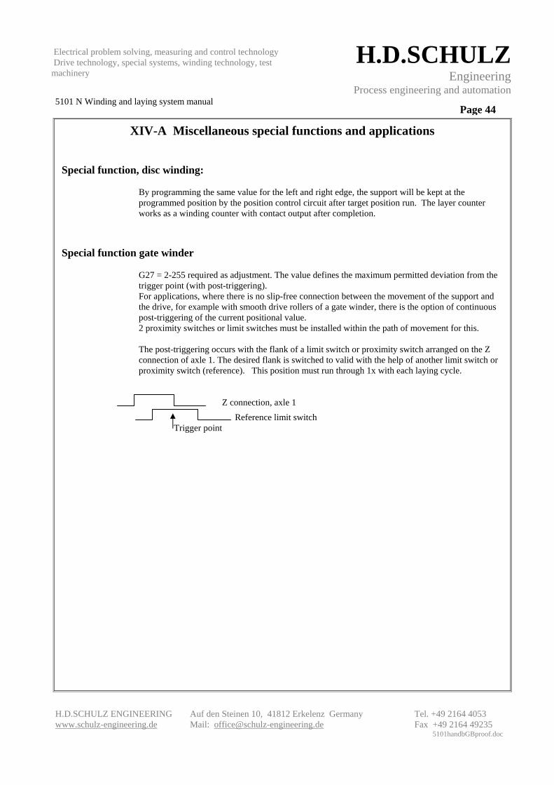
Special function gate winder
G27 = 2-255 required as adjustment. The value defines the maximum permitted deviation from the trigger point (with post-triggering). For applications, where there is no slip-free connection between the movement of the support and the drive, for example with smooth drive rollers of a gate winder, there is the option of continuous post-triggering of the current positional value. 2 proximity switches or limit switches must be installed within the path of movement for this. The post-triggering occurs with the flank of a limit switch or proximity switch arranged on the Z connection of axle 1. The desired flank is switched to valid with the help of another limit switch or proximity switch (reference). This position must run through 1x with each laying cycle.
Electrical problem solving, measuring and control technology Drive technology, special systems, winding technology, test machinery
XV Allocation of the digital inputs and outputs
Version with and without Profibus Function of the basic device inputs: E1 Connection of the reference point limit switch or release window with gate winder E2 Automatic E3 Drive to start position (only after reference run OK) E4 Winding reversed (reversal of the support) E5 Winding sense left (core rotates backwards) E6 End position front or manual mode forward * E7 End position back or manual mode backwards * E8 Drive to unload position * depending on release in the basic data Function of the basic device outputs: A1 Controller release for the servo A2 Reference point OK and ready for operation A3 Layer number reached or length reached A4 End position left follows A5 End position right follows A6 Pre-contact A7 In position (after target run) A8 Alarm Analogue outputs: DAC1 = Target value for traction moment or torque specification (if required) DAC2 = Target value for the support (laying drive) +/- 10V Access to the inputs and outputs of the basic device is additionally possible via the bus with the execution of “Profibus”. (Or-condition)
Electrical problem solving, measuring and control technology Drive technology, special systems, winding technology, test machinery
Function of the options board inputs, (from a hardware point of view only available in versions without Profibus) E11 Core start normal speed E12 Core creeping fixed speed E13 Core backwards E14 Support stop once edge reached E15 Target run in the middle (only with special software as option) E16 Start edge sensing (fully automatic only with special software as option) E17 Measuring probe or mech. scanner probe for edge sensing (special software) E18 Activation of level 2 (presently not assigned) All signals E11-E18 are permanent signals as long as the associated function is desired or present. The signal E16 should only be reset after resetting the confirmation output A12. Function of the options board outputs, (from a hardware point of view available in versions without Profibus) A11 Control release core A12 Edge sensing in action A13 Start the core rotation for edge sensing A14 Reserved A15 Reserved A16 Reserved A17 Reserved A18 Reserved Analogue outputs: DAC3 = Target value for the paddle drive (core rotation) +/- 10 V with paddle control
operating mode DAC4 = Actual signal value material speed +/- 10V with paddle control operating mode Analogue inputs: IN1 = Target value core rotation or material speed with paddle control operating mode
IN2 = Actual dancer value (dancer position) with paddle control operating mode IN3 = External signal value with paddle control operating mode
IN4 = Actual value entry angle with respective operating mode All inputs 0-10 V
Bear in mind that the control of the inputs or evaluation of the outputs e.g. control inhibit, does not mean an shut-
off or drive standstill per the Accident Prevention Regulations
.
A safety shut-off should generally be implemented through releasing or similar actions in accordance with the Accident
Electrical problem solving, measuring and control technology Drive technology, special systems, winding technology, test machinery
XVI Interface to master computer or PC (option)
Master computer function By means of the two interfaces at terminal 2780 it is possible to transfer programs from the master 2780 to the laying station through a command from a superordinate control station
RS232 interface: 9600 baud 8 data bits, 1 Stop bit, no parity
Protocol: All ASCII characters
A Start identifier 0001 Program number 4 digit, leading zeros should be added 01 From laying station 04 To laying station CR Enter ($0D)
Every character is echoed. However, do not wait for the echo.
The example above transfers program number 1 to computers 1 to 4
Possible computer response: B Transfer ended positively F Fault during transfer
The answer is given after the procedure is completed. The laying stations involved must not be in AUTOMATIC mode.
PC function for data backup
The terminal data memory can be backed up and restored with the help of the data backup program provided. Description in Annex I.
Electrical problem solving, measuring and control technology Drive technology, special systems, winding technology, test machinery
XVII Technical data on the 5101 N winding and laying system Issue date 03/2006
Version without Profibus Function: Control of multiple laying stations within a network, winders, unwinders Dimensions: Euroboard, 3 height units, optionally in cartridge for individual installation with integrated power supply unit and options board Connection: via VG edge connector, 64-pole and/or terminal strip with flat cable connection Power supply: 24V DC or AC voltage +/-30%, 0.3A plus external power requirement Displacement transducer inputs Incremental encoder or encoder emulation: Basic device: 2 inputs per channel A,B ; /A,/B,/0
galvanically free with external supply, optional power supply via device 5V= and 15V= limit frequency 100 / (400 ) kHz .. Options board: 1 input channels A,B; /A,/B, galvanically free with external supply, optional power supply via device 5V= and 15V= limit frequency 100 / (400 ) kHz ..
...after quadrupling
Digital control inputs: Basic device: 8 x galvanically free 24V= per 4mA, mutual base point 1x interrupt input reference with gate winder Options board: 8 x galvanically free 24V= per 4mA, mutual base point or Profibus up to 12 Mbit
Analogue inputs: Options board: 4 analogue inputs 0 - 10V , resolution 8 bit non-floating against supply voltage Digital control outputs: Basic device: 8 x galvanically free 24V= 30mA, mutual supply
Options board: 8 x galvanically free 24V= 30mA, mutual supply Analogue outputs: Basic device: 2 analogue outputs +/- 10V, resolution 12 bit driver 5mA non-floating against supply voltage
Options board: 2 analogue outputs +/- 10V, resolution 12 bit driver 5mA non-floating against supply voltage or Profibus up to 12 Mbit Permissible ambient conditions: Ambient temperature 0 to 60 °C Condensation impermissible
Electrical problem solving, measuring and control technology Drive technology, special systems, winding technology, test machinery
Interface: RS 232 or RS 422 network-compatible up to 48 systems Data retention: EEPROM , data retention min. 4 weeks via high energy capacitor. Incremental encoder evaluation: Optionally single, double or fourfold; (factory setting fourfold) partially with intelligent zero track evaluation Deviation correction: max. 32000 Path resolution Support: max. for support 24 bit approx. 2,000,000 incremental encoder pulses
with fourfold evaluation max. for material width 16 bit approx. 8000 incremental encoder pulses with fourfold evaluation with double evaluation double the number of useable pulses
with single evaluation four times the number of useable pulses Path resolution Core: 32000 encoder pulses Numeric range of transmissions: infinite Cycle time: approx. 4 msec per operating mode Operating device: Intelligent mini terminal 2780 2x40 characters, alphanumeric illuminated and function keyboard in addition to numeric key field Operator guidance, bilingual for user data, German, English Power supply unit, interface RS422 Memory space for 200 programs and 10 adjustments Second interface with control technology as optional RS232 Operating unit protection: IP65 with professional installation Resolution of the phys. Input: 0.1mm Core data and edge data 0.1 ° Angle 0.01mm Material data and edge changes
0.001mm Layer growth Input limit values: 0 - 3200.0 mm Core data and 1st target position 0- 3200.0 mm or 0- 9999 mm 2nd target or unloading position 0 - 320.00 mm Material data and edge changes 0 – 25.5 mm Edge offset (correction dimension) EMC : CE conformant for industrial application and installation with consideration to our specifications
Electrical problem solving, measuring and control technology Drive technology, special systems, winding technology, test machinery
Annex I
Program for archiving the system 5101 N program memory
1. System requirements: Microsoft Windows, all versions
2. Installation instructions:
Copy both of the files on the diskette into a new subdirectory. If desired the "minibackup.exe" file can be dragged to the Desktop. Double-clicking on the "minibackup.exe" file opens the program.
3. Preparing the hardware
Connect the data transfer cable to the Miniterminal and the COM1 port on the computer. The Miniterminal must be supplied with power.
4. Program inputs for handling the user application:
Enter the number 2000 in the "start address" field. Enter the number 3EFF in the "Quantity" field. The target and the target file should be entered in the "Filename" field, alternatively this can be implemented via the search function by means of the Windows functionality.
5. Reading out the program memory from the Miniterminal
After entering the target data click in the "READ IN" field in the Miniterminal. The reading out can be monitored with the progress bar. The reading out is confirmed after completion!
Electrical problem solving, measuring and control technology Drive technology, special systems, winding technology, test machinery
6. Transfer to Miniterminal:
After specifying the file click in the "TRANSFER TO MINITERMINAL" legend. The transfer can be monitored by means of the progress bar.
7. Read out the basic and system data stored in the Miniterminal
Select the start address 6000 Enter the number 7FF Enter the file name under which this data is to be saved. Reading out of the Miniterminal is possible at any time.
8. Transfer of basic and system data to the Miniterminal
For the transfer of basic and system data to the Miniterminal the GHD button on the Miniterminal and the password 872 must first be entered (safety lockout).