Manuale istruzioni e catalogo ricambi HD.80 APRICANCELLO OLEODINAMICO Manuale istruzioni e catalogo ricambi Operating instructions and spare parts catalogue Betriebsanleitung und Ersatzteilliste Livret d’instructions et catalogue des pièces de rechange APRICANCELLO OLEODINAMICO HYDRAULIC GATE OPERATOR ÖLDYNAMISCHER TORÖFFNER VÉRIN HYDRAULIQUE
Transcript
Manuale istruzioni e catalogo ricambiOperating instructions and spare parts catalogueBetriebsanleitung und ErsatzteillisteLivret d’instructions et catalogue des pièces de rechangeManual de instrucciones y catálogo de recambiosKsiążeczka z instrukcjami i katalog części wymiennych
Manuale istruzioni e catalogo ricambiOperating instructions and spare parts catalogueBetriebsanleitung und ErsatzteillisteLivret d’instructions et catalogue des pièces de rechange
Dichiarazione CE di ConformitàDichiarazione in accordo alle Direttive 2004/108/CE(EMC); 2006/95/CE(LVD)
Fabbricante: Automatismi CAB SrlIndirizzo: Via della Tecnica, 10 (z.i.) - 36010 Velo d’Astico (VI) - ItaliaDichiara che il prodotto:Attuatore oleodinamico 230Vac per cancelli a battente modello:HD.80è conforme alle condizioni delle seguenti Direttive CE:- DIRETTIVA 2004/108/CE DEL PARLAMENTO EUROPEO E DEL CONSIGLIO del 15 dicembre 2004 concernente il
ravvicinamento delle legislazioni degli Stati membri relative alla compatibilità elettromagnetica e che abroga la direttiva 89/336/CEE, secondo le seguenti norme armonizzate: EN 61000-6-2:2005, EN 61000-6-3:2007.
- DIRETTIVA 2006/95/CE DEL PARLAMENTO EUROPEO E DEL CONSIGLIO del 12 dicembre 2006 concernente il ravvicinamento delle legislazioni degli Stati membri relative al materiale elettrico destinato ad essere adoperato entro taluni limiti di tensione, secondo le seguenti norme armonizzate: EN 60335-1:2002 + A1:2004 + A11:2004 + A12:2006 + A2:2006 + A13:2008; EN 60335-2-103:2003.
CE Declaration of ConformityDeclaration in accordance with Directives 2004/108/CE (EMC); 2006/95/CE (LVD)
The Manufacturer:Automatismi CAB SrlAddress:Via della Tecnica, 10 (z.i.) - 36010 Velo d’Astico (VI) - ItalyDeclares that the product:Hydraulic actuator 230V AC for swing gates, model:HD.80conforms with the requirements of the following EU Directives:
- DIRECTIVE 2004/108/EC OF THE EUROPEAN PARLIAMENT AND OF THE COUNCIL of 15 December 2004, on the harmonisation of the laws of Member States relating to electromagnetic compatibility and which cancels Directive 89/336/EEC, according to the following harmonised regulations: EN 61000-6-2:2005, EN 61000-6-3:2007.
- DIRECTIVE 2006/95/EC OF THE EUROPEAN PARLIAMENT AND OF THE COUNCIL of 12 December 2006, on the harmonisation of the laws of Member States relating to electrical equipment designed for use with certain voltage limits, according to the following harmonised regulations: EN 60335-1:2002 + A1:2004 + A11:2004 + A12:2006 + A2:2006 + A13:2008; EN 60335-1-103:2003.
Déclaration de conformité CEDéclaration en accord avec les Directives 2004/108/CE(CEM) ; 2006/95/CE(DBT)
Fabricant :Automatismi CAB SrlAdresse :Via della Tecnica, 10 (z.i.) - 36010 Velo d’Astico (VI) - ItalieDéclare que le produit :Actionneur oléodynamique 230 Vca pour portails battants modèle :HD.80est conforme aux conditions des Directives CE suivantes :
- DIRECTIVE 2004/108/CE DU PARLEMENT EUROPÉEN ET DU CONSEIL du 15 dècembre 2004 concernant le rapprochement des legislations des États membres relatives à la compatibilité électromagnétique et abrogeant la directive 89/336/CEE, selon les suivantes normes harmonisées: EN 61000-6-2:2005, EN 61000-6-3:2007.
- DIRECTIVE 2006/95/CE DU PARLEMENT EUROPÉEN ET DU CONSEIL du 12 décembre 2006 concernant le rapprochement des legislations des États membres relatives au materiel électrique destiné à être employé dans certaines limites de tension ,selon les suivantes normes harmonisées: EN 60335-1:2002 + A1:2004 + A11:2004 + A12:2006 + A2:2006 + A13:2008; EN 60335-1-103:2003.
CE-KonformitätserklärungErklärung im Einklang mit den Richtlinien 2004/108/CE(EMC); 2006/95/CE(LVD)
Hersteller: Automatismi CAB SrlAnschrift: Via della Tecnica, 10 (z.i.) - 36010 Velo d’Astico (VI) - ItalienErklärt, dass das Produkt:Hydraulischer 230Vac-Antrieb für Drehtoranlagen, Modell:HD.80die Bedingungen der folgenden CE-Richtlinien erfüllt:
- RICHTLINIE 2006/95/EG DES EUROPÄISCHEN PARLAMENTS UND DES RATES vom 12. Dezember 2006 zur Angleichung der Rechtsvorschriften der Mitgliedstaaten über die elektromagnetische Verträglichkeit und zur Aufhebung der Richtlinie 89/336/EWG, gemäß nachstehenden harmonisierten Normen: EN 61000-6-2:2005, EN 61000-6-3:2007.
- RICHTLINIE 2006/95/EG DES EUROPÄISCHEN PARLAMENTS UND DES RATES vom 12. Dezember 2006 zur Angleichung der Rechtsvorschriften der Mitgliedstaaten betreffend elektrische Betriebsmittel zur Verwendung innerhalb bestimmter Spannungsgrenzen, gemäß nachstehenden harmonisierten Normen: EN 60335-1:2002 + A1:2004 + A11:2004 + A12:2006 + A2:2006 + A13:2008; EN 60335-1-103:2003.
Benincà Luigi, Leiter der Rechtsabteilung.Velo d’Astico, den 04/06/2015.
4
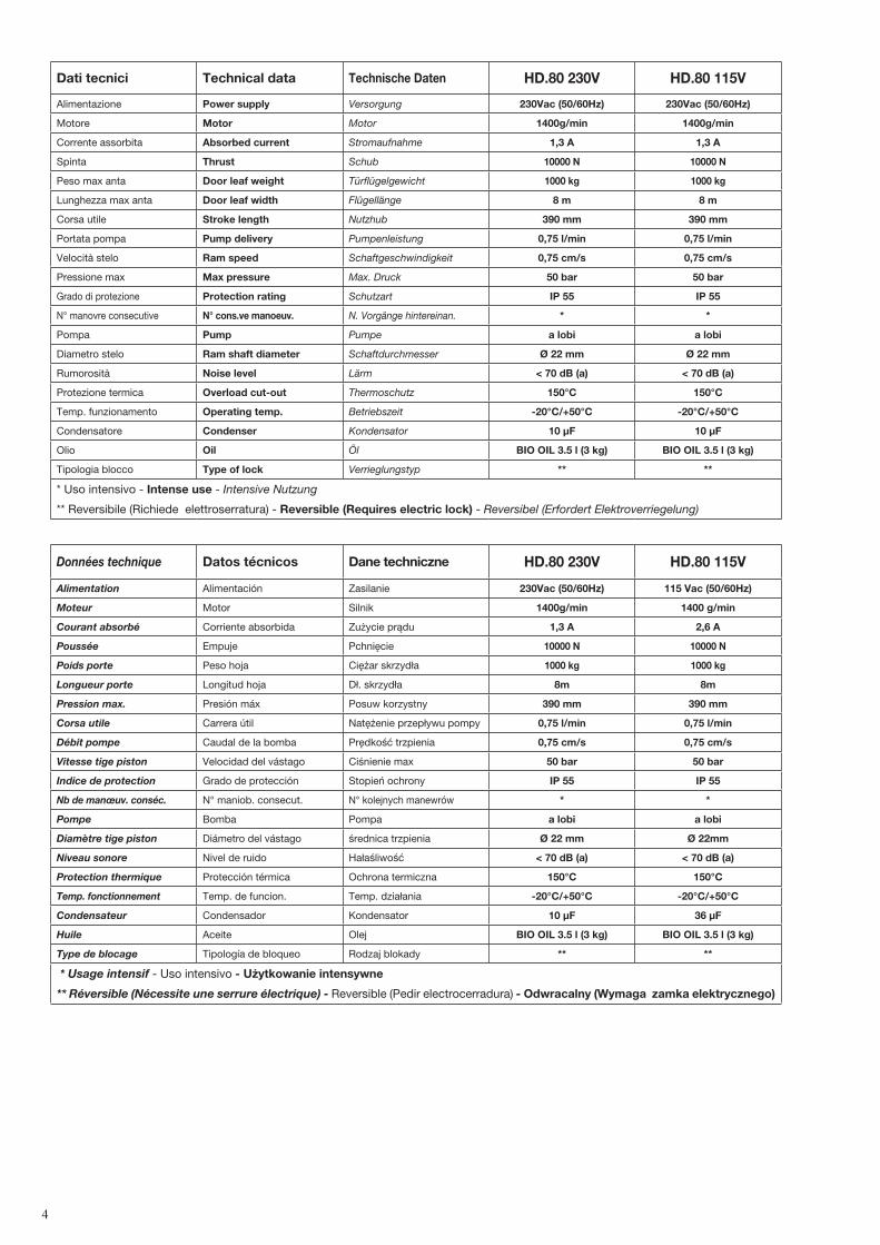
Dati tecnici Technical data Technische Daten HD.80 230V HD.80 115V
Alimentazione Power supply Versorgung 230Vac (50/60Hz) 230Vac (50/60Hz)
Motore Motor Motor 1400g/min 1400g/min
Corrente assorbita Absorbed current Stromaufnahme 1,3 A 1,3 A
Spinta Thrust Schub 10000 N 10000 N
Peso max anta Door leaf weight Türflügelgewicht 1000 kg 1000 kg
Lunghezza max anta Door leaf width Flügellänge 8 m 8 m
Interasse ancoraggi.Distance between axes of anchoring bolts.Die maximale Öffnung der Verankerungen.Entraxe ancrages.Distancia entre ejes ancrajes.Współośowość elementów mocujących.
107
1350
98
390
Mettere a livello.Level.Nivellieren.Mettre de niveau.Nivelar.Ustawić na wysokości
Avvitare o saldare.Bolt or weld.Einschrauben oder schweißen.Visser ou souderAtornillar o soldar.Wkręcić lub zespawać.
Fig. 5
Arresto in chiusura.Stop when closing.Endanschlag zur Schließung.Arrêt en fermeture.Tope de cierre.Chwytak blokujący podczas zamykania.
Arresto in apertura.Stop when opening.Endanschlag zur Öffnung.Arrêt en ouverture.Tope en apertura.Chwytak blokujący podczas otwierania.
Fig. 3
Fig. 4
IMPORTANTE! Estrarre completamente lo stelo e farlo rietrare di circa 10mm prima di fissare la staffa “S” all'anta. IMPORTANT! Slide out the ram shaft completely and then back in by approx. 10mm before fastening bracket “S” to the wing. WICHTIG! Den Schaft ganz ausziehen und um zirka 10 mm wieder einschieben, bevor der „S“-Bügel am Torflügel befestigt wird. IMPORTANT! Extraire complètement la tige du piston et la faire rentrer d’environ 10 mm avant de fixer la patte «S» au vantail. ¡IMPORTANTE! Extraer completamente el vástago y volverlo a meter unos 10 mm antes de fijar el estribo “S” en la cancela. WAŻNE! Wyjąć całkowicie trzpień i wpuścić go na głębokość około 10 mm jeszcze przed zamocowaniem do skrzydła zaczepu „S”.
S
Vs
Rs
Tagliare a misura e saldareCut to size and weldAuf Maß zuschneiden und schweißenCouper à la bonne mesure et souderCortar a medida y soldarWyciąć według rozmiaru i zespawać
GrassoGrease Fett Graisse GrasaSmar
6
10 mm
Fig. 11
Fig. 9
Fig. 7 Fig. 8
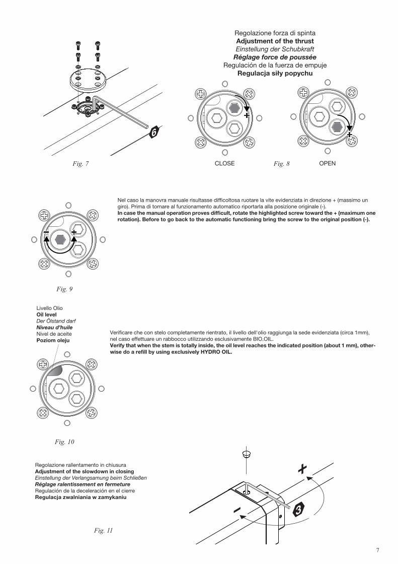
Regolazione forza di spintaAdjustment of the thrustEinstellung der Schubkraft
Réglage force de pousséeRegulación de la fuerza de empuje
Regulacja siły popychu
Nel caso la manovra manuale risultasse difficoltosa ruotare la vite evidenziata in direzione + (massimo un giro). Prima di tornare al funzionamento automatico riportarla alla posizione originale (-).In case the manual operation proves difficult, rotate the highlighted screw toward the + (maximum one rotation). Before to go back to the automatic functioning bring the screw to the original position (-).
Regolazione rallentamento in chiusuraAdjustment of the slowdown in closingEinstellung der Verlangsamung beim SchließenRéglage ralentissement en fermetureRegulación de la deceleración en el cierreRegulacja zwalniania w zamykaniu
Livello OlioOil levelDer Ölstand darfNiveau d’huileNivel de aceitePoziom oleju
7
3
6
6
6
6
6
CLOSE OPEN
Fig. 10
Verificare che con stelo completamente rientrato, il livello dell'olio raggiunga la sede evidenziata (circa 1mm), nel caso effettuare un rabbocco utilizzando esclusivamente BIO.OIL.Verify that when the stem is totally inside, the oil level reaches the indicated position (about 1 mm), other-wise do a refill by using exclusively HYDRO OIL.
Nero= marcia motore e condensatore.Black= motor gear and capacitor.Schwarz= Motorgang und Kondensator.Noir= marche moteur et condensateur.Negro= marcha motor y condensador.Czarny = bieg silnika i praca kondensatora
Marrone= marcia motore e condensatore.Brown= motor gear and capacitor.Braun= Motorgang und Kondensator.Marron= marche moteur et condensateur.Marrón= marcha motor y condensador.Brązowy = bieg silnika i praca kondensatora
Foro di scarico sempre rivolto a terraDrain hole faces the ground
Die Auslassöffnung muss immer zum Boden zeigen
Trou de drainage toujours tourné vers le sol
Orificio de descarga siempre orientado hacia el suelo
Należy uważać na otwór spustowy który powinien być zawsze skierowany do ziemi.
Anta sinistraLeft-hand wingLinker FlügelVantail gaucheHoja izquierdaSkrzydło lewe
Anta destraRight-hand
wingRechter Flügel
Vantail droitHoja derecha
Skrzydło prawe
Legenda:1 Motoriduttore HD.802 Fotocellule3 Selettore a chiave o tastiera digitale4 Lampeggiante5 Antenna6 Centrale di comando.7 Elettroserratura
Legend:1 HD.80 Motor2 Photocells3 Key selector or digital keyboard 4 Beacon5 Antenna6 Control unit.7 Electric lock
Legende:1 HD.80-Getriebemotor2 Photozellen3 Schlüsselwahlschalter oder Digitaltastatur4 Blinkleuchte5 Antenne6 Steuerzentrale.7 Elektroverriegelung
Légende:1 Vérin HD.802 Photocellules3 Sélecteur à clé ou clavier numérique4 Clignotant5 Antenne6 Logique de commande.7 Serrure électrique
Leyenda:1 Motorreductor HD.802 Fotocélulas3 Selector de llave o teclado digital4 Lámpara destellante 5 Antena6 Centralita de comando.7 Electrocerradura
Objaśnienia:1 Siłownik HD.802 Fotokomórki3 Wybierak kluczowy lub klawiatura przy-
ciskowa4 Światło migające5 Antena6 Stacyjka napędowa.7 Zamek elektryczny
3
4
2
5
1
63x1,5 min
230Vac
2
1
2x1,
52x
1
2x1
4x1,5
4x1,5
4x1
RG
58
7
N.B.: Tenere separati i cavi di potenza da quelli ausiliari.N.B.: The power cables must be kept separated from the auxiliary cables.Wichtig: Leistungskabel von Hilfskabeln getrennt halten.N.B.: Séparer les câbles de puissance des câbles auxiliaires.N.B.: Tener separados los cables de potencia de los auxiliares.Uwaga: należy trzymać w oddali przewody zasilania od przewodów po-mocniczych.
IMPORTANTE:L'installazione dell'elet-troserratura è indispensabile.
IMPORTANT: Installation of an electric lock is essential.
WICHTIG: Die Installation der Elektro-verriegelung ist unerlässlich.
IMPORTANT: l’installation de la serru-re électrique est indispensable.
IMPORTANTE: Es imprescindible in-stalar la electrocerradura.
WAŻNE: Instalacja zamka elektrycz-nego jest nieodzowna.
9
Attenzione• Prima di procedere all’installazione leggere le istruzioni qui riportate.• È fatto divieto assoluto di utilizzare il prodotto HYDRO per applicazioni diverse da quelle contemplate dalle presenti
istruzioni.• Istruire l’utilizzatore all’uso dell’impianto.• Consegnare all’utilizzatore le istruzioni ad esso rivolte.• Tutti i prodotti CAB sono coperti da polizza assicurativa che risponde di eventuali danni a cose o persone causati da
difetti di fabbricazione, richiede però la marcatura CE della “macchina” e l’utilizzo di componenti originali CAB.
Notizie generaliAttuatore oleodinamico per cancelli a battente, disponibile in varie versioni:HD.80 230V versione 230 Vac - reversibile - richiede elettroserraturaHD.80 115V versione 115 Vac - reversibile - richiede elettroserraturaTutti i modelli sono dotati di funzione di rallentamento idraulico regolabile in fase di chiusura e di rallentamento fisso in apertura. E' necessario utilizzare pertanto tutta la corsa, rispettando le quote di installazione indicate.
Verifiche preliminariPer un buon funzionamento delle automazioni in oggetto, il cancello da automatizzare dovrà rispondere alle seguenti caratteristiche:- buona robustezza e rigidità.- le cerniere devono presentare giochi minimi e permettere che le manovre manuali siano dolci e regolari.- in posizione di chiusura le ante devono combaciare fra loro per tutta l’altezza.
Arresti meccaniciNel caso non siano già presenti, è necessario predisporre degli arresti meccanici in chiusura ed apertura (Fig.3), indi-pendentemente dal tipo di attuatore installato.L'arresto meccanico in chiusura, in particolare, è indispensabile date le caratteristiche peculiari degli attuatori oleodinamici.
Messa in posa dell’automatismo1 Stabilire l’altezza dal suolo dell’automatismo (si consiglia il più centrato possibile rispetto all'anta ed in corrispondenza
di un solido traverso). Tenere presente che sul fondo dell'attuatore è presente un foro di sfiato che, in particolari condizioni, potrebbe aspirare
dei liquidi (pioggia/neve) all'interno dell'automazione. Per questo motivo è sconsigliata una posizione di installazione in prossimità del suolo.
2 Saldare o fissare la piastra P facendo riferimento alle quote di installazione (Fig.2) e allo schema di montaggio (Fig.5/6): - inserire il perno P sulla staffa P come in figura - inserire nella staffa P la forcella F del motore HD.80 - fissare il tutto con la rondella R ed il dado autobloccante D - rimuovere la vite di chiusura sfiato VS con la sua guarnizione RS. (vedi nota “Vite di sfiato”) Rispettare le quote indicate nelle tabelle di fig. 2, modificando in caso di necessità la lunghezza della piastra. In alcuni
casi può essere necessario ricavare una nicchia nel pilastro. Il rispetto delle quote di installazione è indispensabile per il buon funzionamento dell'attuatore. In riferimento alle tabelle di installazione tenere presente che: Per aperture dell'anta a 90°: A+B deve essere uguale alla corsa dell'attuatore Per aperture dell'anta maggiori di 90°: A+B deve essere inferiore alla corsa dell'attuatore. Mantere la differenza delle quote entro 40mm. Differenze superiori rendono irregolare il movimento dell'anta. Al di-
minuire delle quote A e B aumenta la velocità dell'anta. Rispettare le normative vigenti.3 Estrarre completamente lo stelo e farlo rientrare di circa 10 mm. E' importate lasciare una extra-corsa di sicurezza di 10 mm, sia in chiusura, sia in apertura. La corsa utile indicata
nei dati tecnici e nelle tabelle di installazione è già decurtata di questi 20 mm.4 Mantenendo perfettamente orizzontale l'attuatore, individuare il punto di fissaggio della staffa sull'anta. Saldare o avvitare provvisoriamente la staffa come indicato in Fig.6. 5 Sbloccare l'attuatore e verificare manualmente che l'anta sia libera di aprirsi completamente fermandosi sugli arresti
meccanici di finecorsa e che il movimento dell’anta sia regolare e privo di attriti.6 Fissare definitivamente la staffa.
Nota: Vite di sfiato.A fianco del foro di sfiato è presente un foro cieco dove avvitare la vite e la guarnizione per utilizzi futuri.Appena viene rimossa la vite e durante le prime manovre dell'automazione è possibile si verifichi una piccola fuoriuscita di olio. Ciò è normale e non comporta anomalie di funzionamento.
10
Manovra manuale e d’emergenzaI motoriduttori HD.80, essendo reversibili richiedono semplicemente lo sgancio dell'elettroserratura, dopodiché l'anta può essere manovrata manualmente. Spingere con moderazione l'anta alla sua estremità, accompagnandola per tutta la corsa. La manovra può essere agevolata allentando la valvola di sblocco (Fig.9).
Regolazione forza di spintaL'attuatore è provvisto di un dispositivo antischiacciamento (valvole by-pass) per la limitazione della forza di spinta sull'anta in presenza di ostacolo. Una volta rimosso l'ostacolo l'anta prosegue la sua corsa per il tempo di lavoro impo-stato dalla centrale di comando.• Aprire lo sportellino di protezione (Fig.7), quindi utilizzando una chiave a barra esagonale da 6 mm procedere alla
regolazione della forza (Fig.8).• Sono presenti due valvole regolabili una regola la spinta in fase di apertura (Open), l'altra regola la forza in fase di
chiusura (Close).• Rotando la valvola in direzione + si aumenta la forza di spinta dell'anta viceversa (direzione - ) la forza diminuisce.
ATTENZIONE! Questa regolazione influisce sul grado di sicurezza dell’automazione. Verificare che la forza applicata sull’anta sia conforme con quanto previsto dalle normative vigenti.
Regolazione rallentamentoTutti i modelli sono provvisti di rallentamento in fase di apertura e chiusura, per un movimento più lento dell'anta durante gli ultimi secondi di manovra.Entrambi i rallentamenti avvengono nell'ultima fase di corsa dello stelo, è pertanto importante utilizzare tutta la corsa rispettando le quote di installazione indicate.Il rallentamento in chiusura può inoltre essere regolato mediante l'apposita valvola (Fig.11). Rimuovere il tappo di protezione e utilizzando una chiave a barra esagonale da 3mm:- allentare (rotazione antioraria) la valvola per incrementare la velocità di rallentamento. - fissare (rotazione oraria) la valvola per ridurre la velocità di rallentamento.Allentando al massimo la valvola si disattiva la funzione di rallentamento.Non forzare mai la valvola di regolazione.
Posizionamento delle copertureUna volta effettuata la regolazione del rallentamento è possibile riposizionare le coperture (Fig.12). Prestare attenzione al foro di scarico che deve essere sempre rivolto verso terra.
CollegamentiL'attuatore viene fornito con cavo di collegamento già inserito e collegato (Fig.12). Per il collegamento alla centrale di comando, fare riferimento alla schema e alle istruzioni della centrale di comando.Per proteggere il cavo di alimentazione si consiglia l'utilizzo di una guaina spiralata da 12mm da inserire nell'apposito raccordo.E' obbligatorio effettuare il collegamento di messa a terra.
Rabbocco/sostituzione olioTutti gli operatori oleodinamici richiedono una verifica periodica del livello dell'olio.Per il rabbocco è sufficiente, dopo aver tolto alimentazione di rete all'impianto, rimuovere le 4 viti che fissano la coper-tura (Fig.7).Il livello dell'olio, a stelo completamente rientrato (anta aperta), deve raggiugere la nicchia evidenziata in fig. 10. Utiliz-zare esclusivamente olio BIO OIL.
11
Important• Before installing the operator read these instructions.• Use of a HYDRO product for any application not described in this instruction manual is prohibited.• The user must be instructed on the use of the automation system.• The user must be consigned the instruction manual.• All CAB products are insured against damage or injury caused by manufacturing defects under the essential condi-
tion that the operator has the CE marking and all genuine CAB components are installed.
General InformationHydraulic operator suitable for swinging gates, available in two different versions. HD.80 230V 230V version-reversible- electric lock is neededHD.80 115V 115V version-reversible- electric lock is neededAll the versions are provided with hydraulic slow down adjustable during closing phase and fixed during opening phase. It is necessary to use the whole stroke, complying with the specified installation geometry.
Preliminary ChecksFor the gate automation to work properly, the actual gate must have the following characteristics:- it must be robust and rigid.- the hinges must have only limited play and provide smooth and gentle gate movements.- the whole height of the wings must be in contact when closed.
Gate Stops If they are not already provided, install gate stops on the opening and closing stroke limits (Fig.3) regardless of the type of operator being installed.The mechanical stop in close position is compulsory because of the particular characteristics of the hydraulic actuators.
Installing the automation system1 Establish the height of the automation from the ground (preferably as close to the centre of the wing as possible and
along a solid cross rail). Remember that under the operator there is a vent hole and in certain conditions (e.g. rain or snow) it may draw liquid
into the automation. For this reason it is best not to install the operator too close to the ground.2 Weld or otherwise anchor plate P in place, see installation distances (Fig.2) and the installation diagram (Fig.5): - insert pin P in bracket P as in the figure - insert the fork F of the HD.80 into the bracket P - lock everything in place by washer R and self-locking nut D - remove the vent plug VS with its gasket RS. (see note “Vent plug”) Observe the distances given in the tables at fig. 2, correcting the length of the plate if necessary. In some cases a
recess may have to be made in the post. It is essential that the installation distances are respected for the operator to work correctly. With reference to the installation tables note that: For the wing to open 90°: A+B must be equal to the operator stroke For the wing to open more than 90°: A+B must be less than the operator stroke. Keep the length differences within 40mm. Over this difference the wing movement becomes uneven. When reducing
lengths A and B , increase the wing speed. Comply with all statutory regulations.3 Slide out the ram shaft completely and then slide back in by approx. 10 mm. Lock the operator in place. Always leave a safety overrun of 10 mm in both the closing and opening strokes. The stroke length given in the techni-
cal data and installation tables has already been reduced by the necessary 20 mm.4 Make sure the operator is kept perfectly level and mark the point where the bracket will be attached to on the wing. Temporarily weld or bolt the bracket in place as shown in Fig.6. 5 Release the operator and swing the gate by hand to check it moves freely to fully open and stops on the gate stop.
The wing must move smoothly and evenly.6 Anchor the bracket permanently.
NOTE: Vent plug.Next to the vent a dead hole has been provided where the plug and gasket can be kept for future use.On removing the plug and during the first operator manoeuvres a small quantity of oil may leak out. This is perfectly normal and should not be considered a fault.
12
Manual and emergency gate operation Being reversible, the motors HD.80 can be released simply by unlocking the electric lock, after that the leaf can be operated manually.Slowly push the wing by its outer end, accompanying it all the way to the gate stop. The operation can be made easier by loosening the release valve (Fig.9).
Adjusting the thrustThe operator is equipped with anti-squash by-pass valve that limit the thrust on the wing when it meets an obstacle. Once the obstacle is removed the wing will continue its stroke for the work time set by the control unit.• Open the protective cover (Fig.7) and use a 6 mm hexagonal key to adjust the thrust (Fig.9).• There are two adjustable valves, one governs the opening thrust (Open), the other governs the closing thrust
(Close).• Turn the valve towards + to increase the thrust on the wing and vice-versa (i.e. towards - ) to reduce the thrust.
CAUTION! This adjustment is directly linked to the safety level of the automation. Make sure that the thrust applied on the wing complies with statutory regulations.
Slow down adjustementall the versions are provided with slow down in close and open position for a slower movement during the last seconds of the maneuver.ìThe slow down in both direction starts in the last part of the stroke, so it is very important to use the whole stroke and respect the indicated installation geometry.ìThe slow down in close position can be adjusted by means of the dedicated valve (Fig.11).ìRemove the protection cap and using an allen key by 3 mm:ì-loosen ( counterclockwise rotation) the valve in order to increase the slow down speedì-tighten (clockwise rotation) the valve in order to reduce the slow down speed.Never force the adjusting valve
The protective coversAfter adjusting the slowdown the covers can be replaced (Fig.11). Take great care in ensuring that the drain hole faces the ground.
WiringThe operator is supplied with the wiring cable already installed and wired (Fig.12). To connect it to the control unit see the diagram and instructions for the control unit.The power cable is best protected by a 12mm spiral sheath that has to be inserted in the coupling provided.An earth connection is compulsory.
Topping up/changing oilThe oil level in all hydraulic operators must be periodically checked.To top up the oil first shut-off the mains power to the system and then remove the 4 screws on the terminal block, which also acts as oil cap. The oil level, when the stem is totally inside (open leaf) must reach the cavity showed in fig.10 Only use BIO OIL.
13
14
Achtung• Vor der Installation unbedingt diese Anleitungen lesen.• Es ist absolut verboten, das Produkt HYDRO für andere Anwendungen einzusetzen, als die in dieser Anleitung be-
schriebenen.• Den Benutzer über den Gebrauch der Anlage unterrichten.• Dem Benutzer die für ihn bestimmten Anleitungen aushändigen.• Alle Produkte CAB sind mit einer Versicherungspolice ausgestattet, die eventuelle Sach- oder Personenschäden
abdecken, welche infolge von Fabrikationsfehlern entstehen könnten. Dies setzt jedoch die CE-Kennzeichnung des Geräts und die Verwendung von Originalteilen von CAB voraus.
Allgemeine AngabenÖlhydraulischer Antrieb für Drehtore, der in verschiedenen Versionen verfügbar ist:HD.80 230V: 230 Vac reversibler Antrieb, der ein Elektroschloss benötigt. HD.80 115V: 115 Vac reversibler Antrieb, der ein Elektroschloss benötigt.Alle Antriebe sind mit einer beim Schließen einstellbaren hydraulischen Verlangsamung und einer beim Öffnen festen Verlangsamung ausgestattet. Deshalb ist es notwendig, den ganzen Hub zu verwenden, indem die angegebenen Mon-tage Abmessungen respektiert werden.
Vorbereitende KontrollenFür die einwandfreie Funktion der Automatisierung soll das betreffende Tor die folgenden Merkmale aufweisen:- Es soll robust und ausreichend steif sein.- Die Scharniere sollen Mindestspiele aufweisen und die sanfte, gleichmäßige Betätigung von Hand ermöglichen.- In geschlossener Position sollen die Torflügel über die gesamte Höhe aufeinander passen.
Mechanische SperrenSofern nicht bereits vorhanden, müssen, unabhängig vom installierten Antriebstyp, mechanische Sperren für Schließen und Öffnen vorgesehen werden (Abb. 3).Wegen der besonderen Eigenschaften von den Ölhydraulischen Antrieben, ist der mechanische Endanschlag beim Schließen wesentlich.
Montage der Automatisierung1 Den Abstand der Automatisierung vom Boden bestimmen (es empfiehlt sich eine möglichst zentrale Position im
Vergleich zum Torflügel auf Höhe eines soliden Querträgers zu wählen). Daran denken, dass sich am Boden des Triebs eine Entlüftungsöffnung befindet, durch welches unter bestimmten
Bedingungen Flüssigkeit (Regenwasser, Schnee) in das Innere der Automatisierung eindringen könnte. Aus diesem Grund ist von der Installation in direkter Bodennähe abzuraten.
2 Die Platte P unter Bezugnahme auf die Installationsmaße (Abb. 2) und den Montageplan (Abb. 5/6) anschweißen oder befestigen:
- Den Bolzen P am Bügel P einstecken, wie in der Abbildung gezeigt. - Stecken Sie die Gabel F des Antriebs HD.80 in die Halterung P ein. - Das Ganze mit der Unterlegscheibe R und der selbstsperrenden Mutter D befestigen. - Die Verschlussschraube der Entlüftungsöffnung VS mit der Dichtung RS ausbauen. (siehe Hinweise “Entlüf-
tungsschraube”) Die in der Tabelle der Abb. 2 angegebenen Maße einhalten, wobei gegebenenfalls die Länge der Platte anzupassen
ist. In bestimmten Fällen muss vielleicht eine Nische am Pfeiler vorgesehen werden. Die Einhaltung der Installationsmaße ist für die einwandfreie Funktion des Triebs unerlässlich. Bezüglich der Installationstabellen ist zu bedenken: Für Öffnungen des Torflügels von 90°: A+B muss gleich sein, wie der Hub des Triebs Für Öffnungen des Torflügels von mehr als 90°: A+B muss kleiner sein, als der Hub des Triebs. Die Maßabweichungen dürfen nicht mehr als 40 mm betragen. Größere Unterschiede verursachen eine unregelmäßige
Bewegung des Torflügels. Bei Verringerung der Maße A und B wird die Geschwindigkeit des Torflügels erhöht. Die einschlägigen Normen befolgen.3 Den Schaft ganz ausziehen und um zirka 10 mm wieder einschieben. Es muss unbedingt ein Sicherheits-Überlauf von 10 mm an Verschluss und Öffnung vorgesehen werden. Der unter
den technischen Daten und den Installationstabellen angegebene Nutzhub ist bereits um diese 20 mm gekürzt.4 Den Trieb perfekt waagrecht halten und den Punkt der Befestigung des Bügels am Torflügel ausmachen. Den Bügel provisorisch anschweißen oder anschrauben, wie in der Abb. 6 gezeigt. 5 Den Trieb entriegeln und von Hand prüfen, ob sich der Torflügel ganz öffnen lässt, an den mechanischen Endanschlä-
gen anhält und die Bewegung des Flügels regulär und reibungslos erfolgt.6 Jetzt den Bügel endgültig befestigen.
15
NB: Entlüfterschraube.Neben der Entlüftungsöffnung befindet sich ein Blindloch, in das die Schraube und die Dichtung für zukünftige Nut-zungen eingeschraubt werden können.Sobald die Schraube ausgeschraubt wird, und während den ersten Manövern der Automatisierung, kann unter Um-ständen ein wenig Öl austreten. Dies ist durchaus normal und bedeutet keine Funktionsanomalie.
Manuelle Betätigung und NotbetriebDa die Ölhydraulischen Antriebe HD.80 reversibel sind, muss das Elektroschloss gelöst werden, um den Flügel manuell zu bewegen.Vorsichtig gegen das Ende des Torflügels drücken und diesen auf dem gesamten Weg begleiten. Die Bewegung kann erleichtert werden, indem das Ventil gelockert wird.
Einstellung der SchubkraftDer Trieb ist mit einem Quetschschutz (Bypass-Ventile) zur Begrenzung der Schubkraft an dem Torflügel bei Vorliegen eines Hindernisses ausgestattet. Sobald das Hindernis beseitig ist, setzt der Torflügel seinen Weg für die an der Steu-erzentrale eingestellte Zeit fort.• Die Schutzabdeckung öffnen und mit einem 6 mm-Sechskantschlüssel den Schub einstellen (Abb. 7).• Es sind zwei einstellbare Ventile vorhanden, eines regelt den Schub während des Öffnens (Open), das andere regelt
die Kraft während des Schließens (Close).• Durch Drehen des Ventils in Richtung + wird die Schubkraft des Torflügels erhöht, während umgekehrt (Richtung) die
Kraft verringert wird.
ACHTUNG! Diese Einstellung beeinflusst den Sicherheitsgrad der Automatisierung. Sicherstellen, dass die am Torflügel angewandte Kraft mit den Bestimmungen der einschlägigen Normen konform ist.
Einstellung der VerlangsamungAlle Antriebe sind mit einer Verlangsamung beim Öffnen und Schließen ausgestattet, um eine langsamere Bewegung des Flügels während der letzten Sekunden des Manövers zu erlauben.Beide Verlangsamungen finden in der letzten Strecke des Hubes von der Stange statt. Deshalb ist es wichtig, den ganzen Hub zu verwenden, indem die angegebenen Montage Abmessungen respektiert werden.Die Verlangsamung beim Schließen kann auch durch das geeignete Ventil eingestellt werden (Bild 11).Nehmen Sie den Schutzverschluss weg. Indem Sie einen 3mm Sechskantschlüssel verwenden,- Lockern Sie das Ventil durch eine Drehung gegen den Uhrzeigersinn, um die Geschwindigkeit der Verlangsamung zu erhöhen.- Befestigen Sie das Ventil durch eine Drehung im Uhrzeigersinn, um die Geschwindigkeit der Verlangsamung zu vermindern.Indem das Ventil völlig gelockert wird, wird die Funktion der Verlangsamung abgeschaltet.Schrauben Sie das Regelungsventil nicht zu viel an, sonst könnte das einen Bruch verursachen.
Anbringen der AbdeckungenNachdem die Verlangsamung eingestellt wurde, können die Abdeckungen wieder angebracht werden (Abb. 11). Achtung: die Auslassöffnung muss immer zum Boden zeigen.
AnschlüsseDer Trieb wird mit bereits eingezogenem und angeschlossenem Kabel geliefert (Abb. 12). Für den Anschluss an die Steuerzentrale auf den Schaltplan und die Anleitungen der Steuerzentrale Bezug nehmen.Zum Schutz des Stromkabels wird die Verwendung eines 12 mm Spiralmantels empfohlen, der an dem speziellen Anschlussstück eingesetzt wird.Die Erdung ist obligatorisch vorgeschrieben.
Öl auffüllen/wechselnBei allen öldynamischen Trieben muss regelmäßig der Ölstand kontrolliert werden.Zum Auffüllen die Anlage von der Netzversorgung trennen und die beiden Befestigungsschrauben der Klemmenleiste ausbauen, die auch als Ölstopfen dienen.Wenn die Stange völlig zurückgekehrt ist ( geöffneter Flügel), muss das Öl Niveau die im Bild 10 unterstrichene Nische erreichen. Ausschließlich Öl Hydro OIL verwenden.
16
Attention• Avant de procéder à l’installation, lire les instructions ci-après.• Il est absolument interdit d’utiliser le produit HYDRO pour des applications différentes de celles qui sont décrites
dans ces instructions.• Expliquer à l’utilisateur le mode d’emploi de l’automatisme.• Remettre à l’utilisateur les instructions qui le concernent.• Tous les produits CAB sont couverts par une police d’assurance répondant d’éventuels dommages aux choses ou aux
personnes causés par des défauts de fabrication; cette couverture exige toutefois le marquage CE de la «machine» et l’utilisation de pièces originales CAB.
Informations généralesVérin hydraulique pour portails battants, disponible en différentes versions :HD.80 230V version 230 Vac - réversible – nécessite une serrure électriqueHD.80 115V version 115 Vac - réversible – nécessite une serrure électriqueTous les modèles sont munis de fonction de ralentissement hydraulique réglable en phase de fermeture et fixe en phase d’ouverture. Il sera donc nécessaire d’utiliser toute la course, en respectant les géométries d’installation indiquées.
Contrôles préliminairesPour un bon fonctionnement des automatismes en objet, le portail à automatiser devra posséder les caractéristiques suivantes:- robustesse et rigidité- les charnières doivent présenter un jeu minime et permettre des manœuvres manuelles douces et régulières- en position de fermeture, les vantaux doivent coïncider l’un avec l’autre sur toute la hauteur.
Butées mécaniquesSi elles ne sont pas présentes, il faut prévoir des butées mécaniques en fermeture et en ouverture (Fig.3), indépen-damment du type de vérin installé.L’arrêt mécanique en fermeture, en particulier, est indispensable à cause de caractéristiques particulières des opéra-teurs hydrauliques.
Pose de l’automatisme1 Déterminer la hauteur de l’automatisme par rapport au sol (il est conseillé de le centrer le plus possible sur le vantail
et de le monter au niveau d’une traverse solide). Tenir compte du fait que le fond du vérin présente un trou de drainage qui, dans certaines conditions, pourrait laisser
pénétrer des liquides (pluie/neige) à l’intérieur de l’automatisme. C’est la raison pour laquelle il est déconseillé d’ins-taller l’automatisme trop près du sol.
2 Souder ou fixer la plaque P en se référant à la hauteur d’installation choisie (Fig.2) et au schéma de montage (Fig.5/6): - introduire le pivot P sur la patte P comme sur la figure - introduire la plaque P sur la patte F du moteur HD.80 - fixer le tout avec la rondelle R et l’écrou de sûreté D - enlever la vis de fermeture du trou de drainage VS avec son joint RS. (voir note «vis de drainage») Respecter les distances indiquées dans les tableaux de la fig. 2, en modifiant si nécessaire la longueur de la platine.
Dans certains cas, il peut se révéler nécessaire d’effectuer une niche dans le pilier. Le respect des distances d’installation est indispensable pour le bon fonctionnement du vérin. En suivant les indications des tableaux d’installation, tenir compte que: Pour une ouverture du vantail à 90: la mesure A+B doit être égale à la course du vérin Pour une ouverture du vantail supérieure à 90°: la mesure A+B doit être inférieure à la course du vérin. La différence entre les deux mesures ne doit pas dépasser 40 mm. Des différences supérieures provoquent un mou-
vement irrégulier du vantail. Quand les mesures A et B diminuent, la vitesse du vantail augmente. Respecter les normes en vigueur.3 Extraire complètement la tige du piston et la faire rentrer d’environ 10 mm. Il est important de laisser une surcourse de sécurité de 10 mm, aussi bien en fermeture qu’en ouverture. Dans la
course utile indiquée dans les données techniques et dans les tableaux d’installation, ces 20 mm ont déjà été déduits.4 En maintenant le vérin parfaitement horizontal, identifier le point de fixation de la patte sur le vantail. Souder ou visser provisoirement la patte comme l’indique la Fig.6. 5 Débloquer le vérin et vérifier manuellement que le vantail s’ouvre complètement en s’arrêtant sur les butées méca-
niques de fin de course et que son mouvement est régulier et sans frottements. Fixer la patte de manière définitive.
Note: Vis de drainage.À côté du trou de drainage il y a un trou borgne dans lequel visser la vis et le joint pour des utilisations futures.Quand on enlève la vis et durant les premières manœuvres de l’automatisme, il peut y avoir une petite fuite d’huile. C’est normal et cela ne veut pas dire qu’il y a une anomalie de fonctionnement.
17
Manœuvre manuelle et de secoursLes motoréducteurs HD.80, étant réversibles, en cas de coupure de courant, un simple décrochage de la serrure élec-trique, permet de manœuvrer manuellement le vantail.Pousser avec modération le vantail à son extrémité, en l’accompagnant sur toute la course. La manœuvre peut être facilitée en desserrant la valve de déblocage (Fig.9).
Réglage de la force de pousséeLe vérin est muni d’un dispositif anti-écrasement (soupape de décharge) pour la limitation de la force de poussée sur le vantail en présence d’obstacle. Une fois l’obstacle enlevé, le vantail poursuit sa course pendant le temps de travail programmé dans la logique de commande.• Ouvrir le couvercle de protection, puis en utilisant une clé à six pans de 6 mm, procéder au réglage de la force (Fig.7).• Il y a deux soupapes réglables: une règle la poussée en phase d’ouverture (Open), l’autre règle la force en phase de
fermeture (Close).• En tournant la soupape dans le sens + on augmente la force de poussée du vantail, dans le sens contraire (sens -) la
force diminue.
ATTENTION! Ce réglage a des conséquences sur le degré de sécurité de l’automatisme.Vérifier que la force appliquée sur le vantail est conforme à ce qui est prévu par les normes en vigueur.
Réglage du ralentissementTous les modèles sont munis de ralentissement en phase d’ouverture et fermeture, pour un mouvement plus lent du vantail durant les dernières secondes de manœuvre.Les deux ralentissements ont lieu dans la dernière phase de la course de la tige, pour cette raison il sera donc important d’utiliser toute la course en respect les géométries d’installation indiquées.Le ralentissement en fermeture peut être aussi réglé par la soupape spécifique pour cette fonction (Fig.11).Ouvrir le couvercle de protection, puis en utilisant une clé à six pans de 3 mm :- desserrer (rotation inverse horaire) la soupape pour augmenter la vitesse de ralentissement. - fixer (rotation horaire) la soupape pour réduire la vitesse de ralentissement. En desserrant au maximum la soupape, on désactive la fonction de ralentissement. Ne jamais forcer la soupape de réglage.
Positionnement des cartersAprès avoir effectué le réglage du ralentissement, on peut remettre en place les carters (Fig.11). Faire attention au trou de drainage qui doit toujours être tourné vers le sol.
ConnexionsLe vérin est muni d’un câble de connexion déjà monté et connecté (Fig.12). Pour le raccordement à la logique de com-mande, se référer au schéma et aux instructions de la logique de commande.Pour protéger le câble d’alimentation, nous conseillons d’utiliser une gaine spiralée de 12 mm à introduire dans le rac-cord prévu à cet effet.La mise à la terre est obligatoire.
Remplissage/vidange huileTous les vérins hydrauliques nécessitent un contrôle périodique du niveau d’huile.Pour le remplissage, après avoir coupé l’alimentation de secteur, il suffit d’enlever les 4 vis qui fixent le bornier (Fig.7).Le niveau d’huile, à tige complètement rentré (ventail ouvert), doit arriver au niveau mis en évidence en fig. 10Utiliser exclusivement de l’huile BIO OIL.
Norme di sicurezza• Non sostare nella zona di movimento delle ante.• Non lasciare che i bambini giochino con i comandi o in
prossimità delle ante.• In caso di anomalie di funzionamento non tentare di
riparare il guasto ma avvertire un tecnico specializzato.
Manovra manuale e d’emergenzaHD.80, essendo reversibile richied semplicemente lo sgancio dell'elettroserratura, dopodichè l'anta può essere manovrata manualmente. Spingere con moderazione l'anta alla sua estremità, ac-compagnandola per tutta la corsa. La manovra può essere agevolata allentando la valvola di sblocco.
Manutenzione• Astenersi assolutamente dal tentativo di effettuare ripara-
zioni, potreste incorrere in incidenti; per queste operazioni contattare un tecnico specializzato.
• Verificare periodicamente l’efficienza dei dispositivi di sicurezza e le altre parti dell’impianto che potrebbero creare pericoli in seguito ad usura.
SmaltimentoQualora il prodotto venga posto fuori servizio, è necessario seguire le disposizioni legislative in vigore al momento per quanto riguarda lo smaltimento differenziato ed il riciclaggio dei vari componenti (metalli, plastiche, cavi elettrici, ecc.); è consigliabile contattare il vostro installatore o una ditta specializzata ed abilitata allo scopo.
AttenzioneTutti i prodotti CAB sono coperti da polizza assicurativa che risponde di eventuali danni a cose o persone causati da difetti di fabbricazione, richiede però la marcatura CE della ”macchina” e l’utilizzo di componenti originali CAB.
Libro istruzioni per l’utilizzatore
Aprire lo sportellino di protezione
Hydro
18
6
Nel caso la manovra manuale risultasse difficoltosa ruotare la vite evidenziata in direzione + (massimo un giro). Prima di tornare al fun-zionamento automatico riportarla alla posizione originale (-).
6
HydroUser’s handbook
Safety rules• Do not stand in the movement area of the gate.• Do not let children play with controls and near the gate.• Should operating faults occur, do not attempt to repair
the fault but call a qualified technician.
Manual and emergency gate operation Being reversible, the motors HD.80 can be released simply by unlocking the electric lock, after that the leaf can be operated manually.Slowly push the wing by its outer end, accompanying it all the way to the gate stop. The operation can be made easier by loosening the release valve.
Maintenance• It is mandatory not to carry out extraordinary maintenance
or repairs as accidents may be caused. These operations must be carried out by qualified person-
nel only.• Periodically check safety components and any other parts
of the system that may become hazardous if worn.
Waste disposalIf the product must be dismantled, it must be disposed ac-cording to regulations in force regarding the differentiated waste disposal and the recycling of components (metals, plastics, electric cables, etc..). For this operation it is advis-able to call your installer or a specialised company.
WarningAll CAB products are covered by insurance policy for any possible damages to objects and persons caused by con-struction faults under condition that the entire system be marked CE and only CAB parts be used.
Open the protective cover
6
In case the manual operation proves difficult, rotate the highlighted screw toward the + (maximum one rotation). Before to go back to the automatic functioning bring the screw to the original position.
6
19
Hydro
20
Manuel d’instructions pour l’utilisateur
Normes de sécurité• Ne vous arrêtez jamais dans la zone de mouvement des
portes.• Ne laissez pas les enfants jouer avec les commandes ou
à proximité des portes.• En cas d’anomalies de fonctionnement, n’essayez pas de
réparer la panne mais contactez un technicien spécialisé.
Manœuvre manuelle et de secoursLes motoréducteurs HD.80, étant réversibles, en cas de coupure de courant, un simple décrochage de la serrure électrique, permet de manœuvrer manuellement le vantail.Pousser avec modération le vantail à son extrémité, en l’accompagnant sur toute la course. La manœuvre peut être facilitée en desserrant la valve de déblocage.
Maintenance• S’abstenir impérativement de toute tentative d’effectuer
des maintenances extraordinaires ou des réparations, sous risque d’accident. Contactez un technicien spécia-lisé pour ces opérations.
• Vérifier périodiquement l’efficacité des dispositifs de sécurité et les autres parties de l’installation qui pourraient représenter un risque en cas d’usure.
DémolitionAu cas où le produit serait mis hors service, il est impératif de se conformer aux lois en vigueur pour ce qui concerne l’élimination différenciée et le recyclage des différents com-posants (métaux, matières plastiques câbles électriques, etc...) contactez votre installateur ou une firme spécialisée autorisée à cet effet.
AttentionTous les produits CAB sont couverts par une police d’assurance qui répond d’éventuels préjudices corporels ou matériels provoqués à cause de défauts de fabrication, mais qui requiert toutefois le marquage CE de la “machine” et l’utilisation de pièces de rechange d’origine CAB.
Ouvrir le couvercle de protection
6
Si la manœuvre manuelle s’avère difficile, tourner la vis mis en évidence en direction + (maximum un tour). Avant de retourner au fonctionnement automatique, la reporter à sa position originale (-).
6
21
HydroHandbuch für den Verbraucher
Sicherheitsvorschriften• Nicht im Öffnungsbereich verweilen.• Kinder nicht mit den Steuerungen oder in der Nähe des
Tores spielen lassen.• Bei Funktionsausfällen nicht versuchen, den Schaden
selber zu beheben, sondern den Techniker rufen.
Manuelle Betätigung und Notbetrieb
Da diese Modelle reversibel sind, muss lediglich die Elek-troverriegelung gelöst werden, danach kann der Torflügel manuell betätigt werden. Vorsichtig gegen das Ende des Torflügels drücken und diesen auf dem gesamten Weg begleiten. Dieses Manöver kann durch Lösen des Entriegelungsknaufs erleichtert werden.
Wartung• Es ist absolut untersagt, selbstständig Sonderwartung
oder Reparaturen vorzunehmen, da Unfälle die Folge sein können; wenden Sie sich an den Techniker.
• Regelmäßig die Wirksamkeit der Sicherheitsvorrichtungen und der anderen, bei Verschleiß potentiell gefährlichen Anlagenteile kontrollieren.
EntsorgungWird das Gerät außer Betrieb gesetzt, müssen die gültigen Gesetzesvorschriften zur differenzierten Entsorgung und Wiederverwendung der Einzelkomponenten, wie Metall, Plastik, Elektrokabel, usw., beachtet werden. Rufen Sie Ihren Installateur oder eine Entsorgungsfirma.
AchtungAlle Produkte CAB wurden mit einem Versicherungsschein versehen, der alle eventuellen Schäden an Dingen oder Personen abdeckt, die durch Herstellungsdefekte her-vorgerufen wurden, vorausgesetzt, das Gerät besitzt die Kennzeichnung EU und es wurden original CAB Einzelkom-ponenten verwendet.
Aprire lo sportellino di protezione
6
Nel caso la manovra manuale risultasse difficoltosa ruotare la vite evidenziata in direzione + (massimo un giro). Prima di tornare al fun-zionamento automatico riportarla alla posizione originale (-).
6
14
4
8
7
16
1
5
2
6
3
11
10
1512
17
9
13
22
HYDRO HD.80N° Denominazione - Description - Bezeichnung - Dénomination - Denominación - Określenie Cod.
1 Fondello End plåate Bodenscheibe Fond Fondo Spód C4395003
2 Serbatoio Tank Tank Réservoir Depósito Zbiornik C5667021
3 Tappo End cap Deckel Bouchon Tapón Zatyczka C5837076
4Motore 230V Motor 230V Motor 230V Moteur 230V Motor 230V Silnik 230V C3587072
Motore 115V Motor 115V Motor 115V Moteur 115V Motor 115V Silnik 115V C3587075