Review ArticleCurrent Research Trends and Perspectives on Solid-StateNanomaterials in Hydrogen Storage
Jie Zheng , Chen-Gang Wang , Hui Zhou, Enyi Ye, Jianwei Xu, Zibiao Li ,and Xian Jun Loh
Institute of Materials Research and Engineering, A∗STAR (Agency for Science Technology and Research), 2 Fusionopolis Way,Innovis, #08-03, Singapore, Singapore 138634
Hydrogen energy, with environment amicable, renewable, efficiency, and cost-effective advantages, is the future mainstreamsubstitution of fossil-based fuel. However, the extremely low volumetric density gives rise to the main challenge in hydrogenstorage, and therefore, exploring effective storage techniques is key hurdles that need to be crossed to accomplish the sustainablehydrogen economy. Hydrogen physically or chemically stored into nanomaterials in the solid-state is a desirable prospect foreffective large-scale hydrogen storage, which has exhibited great potentials for applications in both reversible onboard storageand regenerable off-board storage applications. Its attractive points include safe, compact, light, reversibility, and efficientlyproduce sufficient pure hydrogen fuel under the mild condition. This review comprehensively gathers the state-of-art solid-statehydrogen storage technologies using nanostructured materials, involving nanoporous carbon materials, metal-organicframeworks, covalent organic frameworks, porous aromatic frameworks, nanoporous organic polymers, and nanoscale hydrides.It describes significant advances achieved so far, and main barriers need to be surmounted to approach practical applications, aswell as offers a perspective for sustainable energy research.
1. Introduction
Energy serves as the only universal impetus that drives virtu-ally all social and individual activities, such as transportation,residential electricity generation, and commercial applica-tions [1–6]. Because of the rapid growth of the global popu-lation (expected to reach 9.7 billion by 2050) and humanconsumption, the energy demand is going to be continuallyincreasing. Currently, traditional nonrenewable fossil-basedfuels—petroleum, coal, and natural gas—afford more than80% of the global energy. Hence, an energy crisis is inevitableif we continue to consume fossil fuels unscrupulously. As apreliminary speculated, fossil fuels reserve will out of stockshortly, petroleum (40 years), natural gas (60 years), and coal(156 years), for example [6]. Moreover, the greenhouse gasesand other pollutants released by the consumption of fossil-based fuel cause serious havoc to the plant, environment,and climate [7–9]. The period of the explosion demand for
clean, sustainable, and renewable energies is already comeand will continue to last in the next several decades.
Hydrogen is regarded as a nonpolluting, abundant, effi-cient, and low-cost energy vector for a variety of applications,including stationary power supply, distribution, and diversemobile hydrogen-fueled platforms. Because of the highestgravimetric energy density (120MJ/kg), zero emissions ofgreenhouse gases, and water as the only exhaust product atconversion to energy, hydrogen serves as an ideal long-termsolution to energy-related environmental problems [10–17].
Molecular hydrogen (H2) can be directly produced fromboth renewable and nonrenewable sources and has beenwidely studied in different articles [18–26]. Currently, a vari-ety of nonrenewable sources, such as natural gas, naphtha,heavy oil, and coal, have been used to generate H2. The mostwidely used technique to produce hydrogen in the industry isthe steam reforming using fossil fuels [18, 19]. It is a com-mercially mature technology that can be performed with high
AAASResearchVolume 2021, Article ID 3750689, 39 pageshttps://doi.org/10.34133/2021/3750689
efficiency at a low cost. For instance, the hydrogen generationusing steam methane reforming can get high efficiency inthe range of 65 % to 75 % [20]. However, the steamreforming process is complex and along with the emissionof greenhouse gasses such as carbon monoxide and carbondioxide. Other hydrogen production technologies throughreactions with hydrocarbon compounds are including cata-lytic partial oxidation, autothermal reforming, gasificationof coal, and methane decomposition and aromatization.With the development of hydrogen technology, the renew-able energy-based processes of hydrogen production, suchas solar photochemical and photobiological water decompo-sition, water electrolysis, and biomass-conversion, have beendeveloped [21–25]. These methods are eco-friendly and highefficiency; however, due to the high cost, they are unable tobe the technology of choice for the massive production of H2so far.
As a substitution of fossil fuel, hydrogen energy canbring enormous benefits. However, vital technological andeconomic challenges need to be surmounted to achieve asustainable hydrogen economy development. Foremost,among these obstacles is the lack of suitable hydrogenstorage approaches. Despite the largest gravimetric energydensity, hydrogen has a poor volumetric energy density(0.01MJ/L for hydrogen vs. 32MJ/L for gasoline at 0°Cand 1 atm), hampering it in large-scale storing at mild con-dition [15]. The U.S. Department of Energy (DOE) sets thehydrogen capacity targets for onboard storage identifies thesignificance of both gravimetric and volumetric capacity,where the gravimetric and volumetric capacity means thequantity of hydrogen gas contained in a given weight andvolume of the storage system, respectively (Table 1) [14].The ultimate onboard hydrogen storage goal is 0.065 kgH2/kg system and 0.050 kg/L for gravimetric and volumetric,respectively. Typically, a hydrogen storage system containsnot only reactant materials but also tanks, compressors,valves, piping, insulation, and other hardware, which com-prise a significant proportion of the overall cost. Comparewith the pure material storage capacity, the system storagecapacity drops significantly as a need to account for allassociated components mentioned above. Accordingly,the hydrogen storage material with a high capacity(≥10wt% hydrogen) and good reversibility (≥1500 cycles)is intensively desired. Additional requirements for an idealhydrogen storage medium include fast hydrogen uptake/r-elease rate, mild operation, and delivery condition, as wellas low cost.
Though H2 exhibits various advantages over other energyfuels, it is considered a dangerous fuel mainly because it is ahighly combustible gas with a flammability range from 4%to 75% vol in the air and may cause an explosion in the pres-ence of spark, heat, or even sunlight. H2 is colorless and odor-less, and therefore, confronting to discover in case ofleakages. Moreover, own to the density as low as 0.0899 g/Lat standard temperature and pressure (STP, 0°C and 1 atm),the storage of hydrogen with conventional approaches, suchas compression and liquefaction, need high pressure, and/orvery low temperature, resulting in increased leaking risks,and even an explosive if the leakage occurs in a confined sur-
rounding. Hence, safety aspects should be accurately evalu-ated and taken into account during the hydrogen storage,transportation, and utilization, to avoid hydrogen-relatedaccidents (such as the Hindenburg fire in 1937 and thehydrogen explosion in Fukushima nuclear plant in 2011)happen again.
Throughout the past two decades, a great fundamentaladvancement in the hydrogen technique has been witnessed,particularly in the hydrogen storage [10–17]. The traditionalhydrogen storage approach is characterized by physicallyincrease hydrogen gas density using high pressure orextremely low temperature, resulting in the cost and securityconcerns. Additionally, converting hydrogen into liquidhydrogen-rich molecules, such as formic acid, methanol,ammonia, and liquid organic hydrogen carriers, is alsowidely explored for hydrogen storage. However, these liquidmolecules suffer from relatively low hydrogen capacity, intri-cate hydrogenation and dehydrogenation reactions, andcomplicated purification processes. In contrast, physical orchemical storing hydrogen into nanomaterials in the solid-state is a competent and practical alternative (Figure 1)[10–13]. The solid-state hydrogen storage exhibits highhydrogen content, safe, easy for handling, transportation,and tradable.
In this review, we aim to comprehensive summarize theup-to-date solid-state hydrogen storage systems and revealthe related universal rules for hydrogen energy in practicalapplications. In Section 2, different storage nanomaterialsare collated systematically, including nanoporous carbonmaterials, metal-organic frameworks (MOFs), covalentorganic frameworks (COFs), porous aromatic frameworks(PAFs), nanoporous organic polymers, and nanoscalehydrides. Special attention is given to the important roles ofnanoscale hydrides for their conspicuous improvement inthe hydrogen storage performance. In solid hydrogen storagesystems, hydrogen release is triggered by the catalytic dehy-drogenation or thermal stimulation of the carriers. In thethird part, we discuss the applications of hydrogen fuel inboth stationary and mobile platforms. This review concludesby offering developing strategies for endeavouring toimprove hydrogen storage performance toward sustainableand economical applications.
2. Hydrogen Storage Approaches
Hydrogen gas is the lightest gas (density = 0:0899 g/L at STP)in nature. It contains excellent gravimetric energy storagedensity (120MJ/kg) and extremely low volumetric energydensity (0.01MJ/L). Therefore, how to efficiently store thisunusual energy carrier is the persistent agonizing thing towholly develop hydrogen technology. It is believed that thesettlement of this problem could lead to significant prog-ress in hydrogen technology. Besides, in a practical appli-cation, the hydrogen storage system needs to account forthe operation, storage, and transportation efficiency, secu-rity, and cost issues. In this section, different hydrogenstorage systems with benefits and drawbacks are compre-hensively summarized.
2 Research
2.1. Conventional Hydrogen Storage Systems
2.1.1. Compressed Gas. Hydrogen gas pressurized into a con-tainer offers the initial option for hydrogen storage. Toaccomplish the high-pressure storage (350 bar to 700 bar), aspecial tank material is required, which must be lightweight,adequate strength, good thermal conductivity, and economi-cal. Take advantage of the relatively low price and high ther-mic conductivity, some steel- and aluminum-type materialsare utilized in the construction of storage tanks [31, 32]. Nev-ertheless, these metal materials are nondurable, heavy-weight, and increase safety concerns. In contrast to the metalmaterial, carbon fiber reinforced plastic (CFRP) [32–34],with lightweight, sufficient strength, and durable properties,serves as a more promising material for the pressurized gasvessel. While the relatively low thermal conductivity andhigh-price issues need to be solved before the CFRP exten-
sively be used. Underground salt caverns can perform high-pressure gas storage and are applied to stationary storepressured hydrogen gas [35–38]. It is a feasible option forcompressed hydrogen gas storage, with adjustable storagecapacity, high-pressure storage ability, adaptable operatingpressure, and minimized hydrogen leakage. Nevertheless,the salt cavern needs solution mining water and brine dis-posal, near the location of hydrogen production or con-sumption, and suitable geology, which are significantchallenges for its development.
The hydrogen density of the compressed hydrogen gasis 24 g/L at 350 bar and 40 g/L at 700 bar (300K)(Table 2). Because of the increased density, higher hydrogenstorage capacity can be achieved (i.e., 0.052 kg H2/kg systemand 0.0277 kg/L at 700 bar, Table 2). However, they still farshort of the ultimate DOE capacity goals for onboard stor-age for hydrogen-powered vehicles (0.065 kg H2/kg system
Table 1: Summary of the DOE goals for hydrogen storage in onboard vehicular applications [14].
System-based gravimetric capacity kg H2/kg system 0.055 0.065
Volumetric capacity
Material-based volumetric capacity kWh/L 1.3 1.7
System-based volumetric capacity kg H2/L 0.04 0.05
Storage system cost $/kWh net ($/kg H2) 9 (300) 8 (266)
Durability/operability
Operating ambient temperature °C -40/60 (sun) -40/60 (sun)
Min/max delivery temperature °C -40/85 -40/85
Min/max delivery pressure bar 5/12 5/12
Cycle life (uptake/release cycles) cycles 1500 1500
System fill time (for 4-10 kg) min 3-5 3-5
Fuel purity (H2 from storage) %H2 99.97% 99.97%
Transportation
House/buildingDistributed power generation
√ High capacity
√ Improved thermodynamicsand kinetics
√ Security
Hydrogen storage in nanomaterials
H2
H2
Figure 1: Schematic illustration showing the hydrogen storage in nanomaterials and its sustainable applications. Reproducing from ref([12, 13, 27–29], and [30]) with permission.
3Research
and 0.050 kg/L, Table 1). Moreover, the high cost and safetyconcerns caused by the high-pressure operation are obsta-cles to the full development of the compressed gas storagesystem.
2.1.2. Cryogenic Storage. Another way to increase the volu-metric density of hydrogen is liquefaction. The density ofthe liquid hydrogen is 70 g/L at 1 bar and 20K. Even thoughhigher hydrogen storage capacity can be obtained theoreti-cally, the practice efficiency of the liquid hydrogen tankrestricts its applications. Due to the low boiling point of theliquid hydrogen (20K), a special designed metallic double-walled container with the excellent insulation system is nec-essary to maintain the cryogenic temperature.
The most important concern for cryogenic storage isthe hydrogen boil-off. To date, even the best-insulatedcontainer may occur hydrogen evaporation, containerpressure increase, and result in energy efficiency problemsas well as security problems. Also, the high energy require-ments (30 to 33% of the total energy) for hydrogen lique-fying and cost consideration are hindrances of its furtherdevelopment [33, 39].
2.1.3. Cryocompressed Storage. Considering the advantageand disadvantage of the compressed gas and cryogenic stor-age, an alternative hydrogen storage approach, cryocom-pressed storage, has been developed. The relatively lowpressure of this storage method reduces the demand for theexpensive CFRP tank. Additionally, it can minimize hydro-gen boil-off and improve energy efficiency.
In the cryopressurizing storage approach, the density ofhydrogen increases to around 87 g/L at 276 bar at 20K. Thehydrogen storage capacity in the cryopressurized containerincreases to 0.058 kg H2/kg system and 0.043 kg/L, whichmeets the goal of DOE 2025 onboard storage values.Although the relatively higher storage capacity has beenachieved, more vital improvements, including milder thestorage, distribution, and operation condition, improve thehydrogen capacity, reduce the overall cost, and need to bemade to realize the sustainable hydrogen economy develop-ment [40, 41].
2.2. Solid Hydrogen Storage Systems. In contrast to conven-tional storage approaches, material-based methods rely onphysisorption and/or chemisorption to immobilize and storehydrogen in solid-state. Material-based hydrogen storage isgenerally considered a safer and practical alternative to con-ventional liquid or gaseous storage due to the stable energystates of the hydrogen composites, low operational hin-drance, and release-on-demand nature [42–45]. In the solid
hydrogen storage system, the interaction between thehydrogen and nanomaterials seriously affects the materialhydrogen storage performance. Typical three absorptionprocesses are summarized (Table 3) [46]. The first type ismolecular hydrogen weakly bonded or trapped on the surfaceof nanoporous materials (adsorbents) via van der Waalsinteractions. However, due to the weak interaction energy(generally less than 10 kJmol–1) between the matrix and thenonpolar hydrogen molecules, the immobilized hydrogencould be spontaneously released from the matrix at high tem-perature. Therefore, cryogenic temperature, e.g., 77K (–196°C), is commonly applied for the storage capability evalu-ation. On the other hand, hydrogen storage and applicationsat room temperature are practically desired but requiredgreat efforts to achieve [47, 48]. Porous nanostructured mate-rials with high surface area are advantageous to increase thehydrogen storage density due to their low density and highporosity [44, 49, 50]. Nanoporous carbon materials (Section2.2.1), metal-organic frameworks (MOFs, Section 2.2.2),covalent organic frameworks (COFs, Section 2.2.3), porousaromatic frameworks (PAFs, Section 2.2.4), and nanoporousorganic polymers (Section 2.2.5) are widely investigatedexamples for hydrogen storage and will be introduced below(Figure 2). The second type of interaction between the hydro-gen and nanomaterials is atomic hydrogen form chemicalbond that strongly binds with material (the interactionenergy is arranged from 100 to 200 kJmol–1). In chemicalstorage approaches, hydrogen is stored in a solid materialsby chemical bonding and released through chemical reac-tions under specific conditions. In this review, nanoscalehydrides will be discussed separately in the following subsec-tion. The last hydrogen/materials interaction type is quasi-molecular interaction or termed Kubas interaction. It isenergetically between physisorption and chemisorption, withan enthalpy of -20 to -70 kJ/mol H2 and a binding energybetween 0.1 and 0.8 eV. In this case, the covalent bondbetween the hydrogen molecules is weakened by the chargetransfer or the polarization induced by the metal in the nano-materials, leading to a shorter distance between the molecu-lar hydrogen and material (~0.254 nm for the Kubasinteraction vs. more than 0.3 nm for the physisorption).Accordingly, based on such designing principles, an idealhydrogen storage material with high storage capacity andoutstanding ab(de)sorption properties at mild condition ispromising to be achieved shortly.
2.2.1. Nanoporous Carbon Materials. Due to the highporosity, low density, and cost efficiency, nanoporous car-bon materials have been considered to be promising car-riers for hydrogen storage [58, 59]. Nanoporous carbon
Table 2: Estimated performance for conventional hydrogen storage approaches.
H2 Storage system H2 density (g/L) Gravimetric (kg H2/ kg system) Volumetric (kg H2/L)
Compressed gas (350 bar, 300 K) 24 0.055 0.0185
Compressed gas (700 bar, 300 K) 40 0.052 0.0277
Cryogenic storage (1 bar, 20 K) 70 ~0.05Cryocompressed (276 bar, 20 K) 87 0.058 0.043
4 Research
materials and their precursors are abundant in nature witha variety of forms, e.g., activated carbon (AC), carbonnanotubes (CNTs), and carbon nanofibers (CNFs). Thesenanoporous carbon materials show a broad diversity intheir material structures and synthetic approaches, offeringvaried compositions, pore sizes, surface areas, and function-alities for hydrogen storage. Table 4 summarized theselected nanoporous carbon materials and their hydrogenstorage properties.
AC has been regarded as a potential candidate for gasstorage purposes due to its extremely low cost, commercialavailability, and availability on chemical modification [60,61]. AC generally displays a high degree of porosity, indicat-ing a surface in exceed 3000m2 g–1. Generally, the physicaladsorption of hydrogen in carbonmaterials follows the Lang-
muir isotherm model, indicating a monolayer adsorption onthe surface [62, 63]. The high surface area of AC enhances thephysical adsorption capacity, particularly at cryogenic tem-perature and high pressure. However, due to the thermalinstability of the absorption interaction (van der Waalsforce), modification of AC to increase the heat of adsorptionbetween AC and hydrogen molecules is vital for the improve-ment of gas intake capability. Theoretically, the hydrogenuptake of AC could achieve 4.0wt% at 77K but less than1.0wt% at room temperature and 100 bar, leading to poorcommercial practicality [64, 65]. Chemical modifications,such as potassium hydroxide (KOH) treatment and metaldoping, are applied to improve the hydrogen storage per-formance of AC [66–68]. Sevilla, Mokaya, and Fuertesreported an AC material preparing from a polypyrrole
Figure 2: Overview and examples of the solid hydrogen storage systems. (a) Nanoporous carbon materials (carbon nanotube (CNT), (b)MOF, (c) COF, (d) PAFs, (e) the structure of a nanoporous organic polymer (PIM-1) and the composite with a nanoporous filler, and (f)nanohydrides (sodium alanate (NaAlH4)) confined in the nanopores of a MOF (MOF-74) [27, 51–56]. Reproduced with permission [56].Copyright 2019, American Chemical Society. Reproduced with permission [57]. Copyright 2018, Wiley-VCH. Reproduced withpermission [52]. Copyright 2015, American Chemical Society. Reproduced with permission [53]. Copyright 2009, Wiley-VCH.Reproduced with permission [53]. Copyright 2009, Wiley-VCH. Reproduced with permission [55]. Copyright 2013, Materials ResearchSociety and Cambridge University Press.
5Research
precursor and KOH treatment exhibited a high surface areaas 3000−3500m2 g–1 and hydrogen storage capacity of up to7.03wt% at 77K and 20bar [69].
The hydrogen spillover technique has been reported as aneffective approach to enhance the binding energy betweenhydrogen molecules and carbon material surfaces at roomtemperature [70–72]. Hydrogen spillover is a multiple-stepprocess, including dissociation of hydrogen from the metalsurface, hydrogen diffusion to the support surface, and com-bination/desorption cycles of the mobile hydrogen species onthe support surface, although investigation is still processingto discover the underlying mechanism of spillover effect(Figure 3). Doping with transitional metals, such as platinum(Pt), palladium (Pd), and nickel (Ni), on hydrogen storagematerials was found to increase the hydrogen storage capa-bility and stability due to spillover phenomenon. ACs withPt and Pd doping demonstrated 1.10wt% and 5.50wt%hydrogen intake capabilities at 298K with 100 bar and80 bar, respectively [73–75]. Several green processes have alsobeen applied to produce AC by using plant fibers, coconutshell, or oilseeds as the raw materials [76]. Ngadi and thecoworkers reported the use of fruit bunch to produce ACfor hydrogen storage, showing a maximal 2.14wt% H2 intakeat 77K and 19bar [77].
Hydrogen storage in carbon nanotubes (CNTs) has alsobeen intensively investigated. CNTs are with diameters inthe range of a nanometer and refer to single-wall carbonnanotubes (SWCNTs) and multiwall carbon nanotubes(MWCNTs) consisting of nested single-wall carbon nano-tubes [78, 79]. Such nanostructure allows CNTs to storehydrogen in their microscopic pores or within the tube struc-tures, possessing an estimated capacity of 5 to 10wt% basedon the early work of Dillon and the coworkers in 1997 [80].Experimental results showed that the hydrogen storagecapacity of SWCNTs and MWCNTs reached 4.5–8wt% at77K and a moderate capacity of approximate 1wt% at ambi-ent temperature and pressure [81–83]. The hydrogen storagecapacity of MWCNTs could be significantly improved underhigh-pressure environments, e.g., 2.0wt% at 40 bar, 4.0wt%at 100 bar, and 6.3wt% at 148 bar, at room temperature[84]. Similar with AC, mental-doping is also effective toenhance the storage capability of CNTs. It was reported thatthe Li-doped MWCNTs offered a hydrogen uptake up to20wt% at room temperature and 1 bar [85]. The other potas-sium- (K-) doped MWCNTs could also achieve up to 14wt%hydrogen uptakes under ambient conditions [85]. Moshfeghet al. expended the scope of doping elements to calcium (Ca),cobalt (Co), iron (Fe), Ni, and Pd on MWCNTs and
investigated their hydrogen storage capabilities, showing0.3wt%, 1.05wt%, 1.5wt%, 0.75wt%, 0.4wt%, and 7.0wt%hydrogen intakes under ambient conditions, respectively[86]. This result indicated Pd would be the most promisingdoping element. It is noted that the defects, such aspentagon-heptagon pair, the substitution of heteroatoms (B,N, or P), and topological distortion, could improve thehydrogen adsorption binding energies and storage capabilityof SWCNTs [51, 87].
Another nanoporous carbon material for hydrogen stor-age application is carbon nanofibers (CNFs). CNFs exhibit ahigh surface area and excellent mechanical properties. Syn-thesis methods of CNFs include chemical vapor deposition,electrospinning technique, and templating methods [88].
These methods are simple and suitable for mass production,which make CNFs as a potential candidate due to the lowcost and commercial availability. Early researches indicatedthat the hydrogen storage capability of CNFs ranged from0.7wt% to 6.54wt% at room temperature and approximately100 bar [89–91]. The deviation was attributed to themanufacturing methods of CNFs. In this decade, CNFsobtained by chemical activation treatment are of great inter-est due to their increased surface area and controllable poresizes [92–96]. As the other carbon materials, chemical treat-ment by using hydroxide salts, carbonate salts, zinc chloride,and phosphoric acid was reported. Ni-doped GNFs obtainedby metal doping showed an enhanced hydrogen uptake as2.2wt% at 298K and 100 bar [97]. It is noted that the
(a) (b)
(c) (d)
(e)
H HH
H
H
H
H
H
H
HMetal particle
H
H
HH
HH
H HHH
H
H H
HH
HH
HH
HHH H
HHHH
HHH
H
H
H
Source
Support
Receptor
Bridge
Figure 3: Hydrogen spillover mechanism in a supported catalyst system: (a) adsorption of hydrogen on a supported metal particle; (b) thelow-capacity receptor; (c) primary spillover of atomic hydrogen to the support; (d) secondary spillover to the receptor enhanced by aphysical bridge; (e) primary and secondary spillover enhancement by improved contacts and bridges. Reproduced with permission [71].Copyright 2005, American Chemical Society.
7Research
hydrogen storage capability of nanoporous carbon materialsis highly dependent on their fabrication methods, shapes,impurity contents, oxygen-containing functionalities, andadsorbed (doping) species. The mass production of nanopor-ous carbon materials with stable qualities and cost efficiencyis highly important for commercial applications. Finally,except AC, CNTs, and CNFs, other nanoporous carbonmaterials, e.g., zeolite, graphene, graphite oxide, and fuller-ene, are also studied and used for hydrogen storage materials[58, 59, 98, 99]. The diversified structures and naturallyabundance of these carbon materials are highly beneficialfor material design and production to match the requirementof hydrogen storage purpose.
2.2.2. Metal-Organic Framework. Metal-organic frameworks(MOFs) are crystalline porous materials consisting of metalion clusters and organic ligands (Figure 4(a)) [57, 100–107].MOFs are highly porous with micropores (<2nm) and acontinuous skeleton. Several synthetic methods have beendeveloped to produce two-dimensional (2D) and three-dimensional (3D) MOFs through coupling metal-containingclusters with multidentate organic ligands, e.g., sulfonates,carboxylates, imidazolates, and tetrazolates [108, 109].Thus, the selection of metal ions and organic buildingblocks allows the control of framework topology, pore size,and surface area. Due to the defined structures with high
porosity and surface area, MOFs have been attracting exten-sive interest as a powerful candidate in the field of gas storagein the past two decades. Several comprehensive reviews haveshown the design, synthesis, and applications of MOFs forhydrogen storage [57, 109–111]. The examples of MOFs andtheir hydrogen storage properties are summarized in Table 5.
The first example of using MOFs for hydrogen storageapplications was reported by Yaghi’s group in 2003 [112].MOF-5 was synthesized from zinc salt and 1,4-benzenedicar-boxylic acid (BDC) to give Zn4O(BDC)3 and exhibited ahydrogen intake of 4.5wt% at 78K and 1.0wt% at room tem-perature and 20 bar, opening a new avenue for hydrogenstorage materials (Figure 4(b)). However, MOF-5 exhibitedpoor moisture-stability, leading to limited applicable envi-ronments and unstable performance. The change in structuretopology and chemical linkage resulted in enhanced mois-ture, thermal, mechanical, and acid/base stabilities as wellas porosity. For example, the BDC linker in MOF-5 wasreplaced with other rigid and bulky moieties, e.g., 1,3,5-benzenetribenzoate (BTB), to increase the porosity andhydrogen storage capacities (Figure 4(c)) [113, 114]. Theobtained MOF-177 carried a BET surface area of4600m2 g–1 and a hydrogen intake of 7.5wt% at 77Kand 70 bar. The substitution of linkers, metal ions, andfunctional groups was applied to synthesize a series of isore-ticular MOFs for improved stability and capability [100]. For
(a)
Organic ligand
(b) (c)
Metal ion
n=1n=2
n=4
n=6Secondary building units Metal-organic framework
MOF-5Surface area: 2500 m2 g–1
MOF-117Surface area: 4600 m2 g–1
BDC BDC
O
O
HO
OH
O
O
OHO
OH
OH
Figure 4: (a) Schematic illustration of the mechanism and formation of metal-organic frameworks (MOFs) [102]. (b) Chemical structure ofBDC and MOF-5 and (c) BDC and MOF-177. The structures of MOFs are reproduced with permission [109]. Reproduced with permission[102]. Copyright 2019, Multidisciplinary Digital Publishing Institute. Reproduced with permission [109]. Copyright 2012, AmericanChemical Society.
8 Research
example, the introduce ethynylene units into the p-phenyleneand the carboxylic groups in MOF-5 give novel COFs withsimilar skeletons but with superior properties [52, 115,116]. The obtained NU-100 has a BET surface area of
6143m2 g–1 and a hydrogen uptake capacity of 10.0wt% at77K and 56bar. The other NU-110 has a BET surface areaof 7140m2 g–1 with a hydrogen capacity of 8.82wt% at 77Kand 45 bar. Another MOF-399 with a high surface area of
Table 5: Experimentally measured hydrogen storage properties of selected MOFs, COFs, and PAFs.
FrameworkStorage conditionsTemp. (K)/Press. (bar)
BET surface area (m2 g–1) Hydrogen capability (wt%) Ref
MOF-5(a) 78/20(b) 298/20
2500−3000 (a) 4.5(b) 1.0
[112]
IRMOF-8 298/10 1801 2.0 [112]
MOF-177(a) 78/70(b) 298/100
4600(a) 7.5(b) 0.62
[113, 114]
NU-100 77/56 6143 10.0 [52]
NU-109 77/45 7010 8.30 [115, 116]
NU-110(a) 77/45(b) 298/180
7140(a) 8.82(b) 0.57
[115, 116]
MOF-399(a) 77/56(b) 298/140
7157(a) 9.02(b) 0.46
[116]
Cr-MIL-53 77/16 1020 3.1 [117]
Al-MIL-53 77/16 1026 3.8 [117]
Cu-MOF-5(a) 77/65(b) 298/65
1154(a) 3.6(b) 0.35
[118]
MOF-210(a) 77/80(b) 298/80
6240(a) 17.6(b) 2.7
[118]
Be-MOF(a) 77/ 1.0(b) 298/95
4030(a) 1.6(b) 2.3
[122]
COF-1(a) 77/1.0(b) 77/70
711(a) 1.7(b) 3.8
[135]
COF-5(a) 77/1.0(b) 77/80
1590(a) 0.1(b) 3.4
[135]
COF-102(a) 77/1.0(b) 77/100
3620(a) 0.5(b) 10.0
[135, 136]
COF-102-3(a) 77/100(b) 300/100
–(a) 6.5(b) 26.7
[139]
COF-105(a) 77/1.0(b) 77/80
3472(a) 0.6(b) 10.0
[134, 135]
COF-108(a) 77/1.0(b) 77/100
4210(a) 0.9(b)10.0
[131–133]
CTC-COF 77/1.1 1710 1.12 [140]
COF-105 (Li-doped) 298/100 – 6.84 [145]
COF-108 (Li-doped) 298/100 – 6.73 [145]
COF-340-CoCl2 298/250 7400 7.00 [146]
PAF-1 77/48 5600 7.0 [27]
PAF-3 77/60 2932 5.5 [149, 150]
PAF-4 77/60 2246 4.2 [149, 150]
PAF-1 (KOH-treated) 77/1.0 1320 3.06 [151]
PAF-1 (Li-doped) 77/1.2 – 10 [153]
PAF-4 (Li-doped) 77/100 5525 20.7 [152]
PAF-4 (Li-doped) 233/100 5525 4.9 [152]
PAF-Mg 233/100 4479 (Langmuir) 6.8 [154]
PAF-Ca 233/100 4479 (Langmuir) 6.4 [154]
PAF-324 298/100 5372 (specific) 6.32 [155]
PAF-334 298/100 – 16.03 [155]
9Research
7157m2/g also shown a high hydrogen uptake capability of9.02wt% at 77K and 45 bar [116]. Several metal ions couldbe applied to build MOFs. Férey and coworkers reportedchromium- and aluminum-based MOFs, i.e., Cr-MIL-53and Al-MIL-53, showing hydrogen uptakes of 3.1wt% and3.8wt% at 77K and 16bar, respectively [117]. Panella et al.used copper(II) ions and benzene-1,3,5-tricarboxylate(BTC) to prepare a MOF (Cu-MOF-5), Cu3(BTC)2, exhibit-ing BET surface area of 1154m2 g–1 and a maximum hydro-gen uptake of 3.6wt% at 77K and 0.35wt% at roomtemperature and 65bar [118]. These results indicated theproperties, and pore sizes of MOFs could be tuned by select-ing the building blocks and linkers.
However, one of the major limitations of MOF is theweak van der Waals interaction between hydrogen atomsand MOFs. The isosteric heat for hydrogen adsorption ofMOFs is generally less than 10 kJmol–1 [109, 119]. This weakinteraction energy is strong enough for applying MOFs forhydrogen storage under cryogenic conditions. However, thestorage capability of MOFs sharply deteriorates when operat-ing at room temperature. It is noted that the isosteric heatshould be increase to 15–20 kJmol–1 to stabilize the hydrogenatoms on MOF surfaces at room temperature [120]. One ofthe highest capacities of hydrogen storage in MOFs wasachieved by using MOF-210 as 17.6wt% at 77K and 80bar;however, the uptake decreased to 2.7wt% at 298K and80 bar [28]. The introduction of active metal sites and thecontrol of pore size and functionalization in MOFs are twowell-developed strategies to improve the isosteric heat. Anumber of metals, e.g., lithium (Li), sodium (Na), K, Magne-sium (Mg), Ca, beryllium (Be), titanium (Ti), Pt, Pd, copper(Cu), Fe, Co, Ni, and zinc (Zn), in element or ion forms havebeen applied as clusters or on MOF decoration [121]. Longand coworkers reported the use of Be12(OH)12(BTB)4 MOF(Be-MOF) could absorb hydrogen with 2.3wt% at 298Kand 95bar, which is a sharp contrast as topically similarMOF-177 with a 0.62wt% hydrogen uptake at 298K and100 bar [122]. Detailed discussions on MOF modificationand doping for gas storage applications could be found inother reviews [57, 109–111, 123]. The varied design and syn-thesis from extended organic building blocks to functionalMOFs are still a popular and impactful research topic.
In addition to experimental investigations, some theoret-ical studies of molecular simulations have also been per-formed for clarifying the mechanism and screening highhydrogen capture materials. Space and the coworkers usedMonte Carlo simulation to model hydrogen sorption inMOFs [104]. It demonstrated that the MOFs should haverelatively small pores and interconnected pores with highsurface area to create strong MOF-H2 interactions. Addition-ally, polarization interactions also played a critical role forhydrogen stabilization in MOFs. Froudakis and coworkersapplied ab initio calculations to confirm that the interactionenergies between the hydrogen molecules and the Li-modified MOFs are significantly enhanced, which can becontributed to the high degree of polarization of hydrogenmolecules [105]. Therefore, MOFs with a charged or dopedframework with narrow pores and exceptional internalsurface area for enhancing their van der Waals interaction
and polarization interaction (Kubas-type interaction) areexcellent hydrogen storage candidates. The theoreticalinvestigation of hydrogen storage in MOFs and COFs is sum-marized in the other review [106]. Recent advances in high-performance computers allow first-principles moleculardynamics to simulate the various diffusion processes ofhydrogen molecules inside MOF structures, providing a clearpicture of the diffusion mechanism of hydrogen molecules innanoporous materials [107].
2.2.3. Covalent Organic Framework. Nanoporous organicpolymers consisting of organic skeletons with lightweightelements, such as C, H, N, O, and B, exhibited low density,low cost, high stability, and structure versatility [124–127].Like MOFs, these nanoporous organic polymers haveattracted great interest for hydrogen storage owing to theirhigh surface areas. Moreover, nanoporous organic polymerspresent advantages over MOFs and carbon materials on theirtunable structures and postsynthetic functionalizationthrough sophisticated synthetic and polymerization tech-niques [128, 129].
COFs are carbon-based crystalline nanoporous organicpolymers and constructed with strong covalent linkages,e.g., B-O, C-O, B-C, C-C, and C-N, to give 2D and 3D struc-tures. Figure 5 shows examples of chemical reactions for syn-thesizing COFs. COFs are with high porosity, well-orderpores, and superior chemical and thermal stability [53,130]. Due to the above advantages, COFs as one of the pow-erful candidates for hydrogen storage have been researchedtheoretically and experimentally in the past 15 years [131,132]. The examples of COFs and their applications on hydro-gen storage are shown in Table 5. The design, synthesis, andapplications beyond hydrogen storage of COFs have beensummarized in other reviews [124–127].
In 2005, Yaghi’s group pioneered the research on COFsand reported a series of porous COFs [133]. For instance,COF-1 was synthesized by using a self-condensation reactionof 1,4-benzenediboronic acid, and COF-5 was prepared from1,4-benzenediboronic acid and 2,3,6,7,10,11-hexahydroxytri-phenylene. COF-5 exhibited a high BET surface area as1590m2 g–1 and a 3.5wt% hydrogen intake at 77K and80 bar. Another 3D-COFs family, including COF-102,COF-105, and COF-108, were also synthesized, showing alarger surface area than 2D COF-5 [134]. Among theseCOFs, COF-102 has a BET surface area of 3620m2 g–1, andits hydrogen uptake capacities are 7.2wt% at 77K and35 bar and 10.0wt% at 77K and 100 bar (Figure 6) [135–138]. It is also noted that the hydrogen volumetric uptakeof COF-102 achieved 40.4 g L–1, which is the best perfor-mance of these 3D-COFs. The phenylene groups in theCOF-102 backbone could be substituted by diphenyl, triphe-nyl, and naphthalene pyrene groups, giving COF-102-2,COF-102-3, COF-102-4, and COF-102-5, respectively[139]. The modulation of the backbone and pore size couldfurther control the hydrogen uptake capacity of COFs.COF-102-3 demonstrated 26.7wt% and 6.5wt% hydrogenuptakes at 77 and 300K under 100 bar, respectively. Thehydrogen uptakes of COF-105 and COF-108 at 77K are
Figure 6: Molecular structures of building units (a) and crystal structures of COFs (b–g). Hydrogen atoms are omitted for clarity. Carbon,boron, oxygen, and silicon atoms are represented as gray, orange, red, and blue spheres, respectively. Reproduced with permission [135].Copyright 2008, American Chemical Society.
BOH
OHB
O BO
BOCN
NN
N
BOH
OH
HO
HO+ B
O
O
NH2O+ N
NH2 + O
O
O
N
O
OBr +
HO
HOB
X
NO2 NN
O
HO
Boroxine linkage
(a) (e)
Triazine linkage
Triazine
(b)
Boronate ester linkage Trans-azodioxy linkage
(f)
(c)
(d)
Imine linkage
Imide linkage Suzuki-Miyaura coupling
Homo coupling
(g)
(h)
Figure 5: Examples of chemical reactions for synthesizing covalent organic frameworks.
11Research
10.0wt% at 80 bar for COF-105, and 10.0wt% at 100 bar forCOF-108. Zheng and coworkers reported a bowl-shapedCOF from cyclotricatechylene (CTC) and 1,4-benzenedi-boronic acid [140]. The CTC-COF has a BET surface areaof 1710m2 g–1 and a hydrogen uptake of 1.12wt% at 77Kand 1.1 bar. The superior hydrogen uptake capacity ofCTC-COF could be attributed to the additional adsorptionin the bowl-shaped CTC cavity.
COFs present excellent hydrogen storage capacity underhigh pressure. However, as MOFs, the capacity deterioratessharply when operating at an increased temperature. Toovercome this problem, metal-doping has been applied toCOFs to improve the hydrogen storage capacity [129, 132].Several computational and experimental studies have beenreported to use metal ions or elements, such as Li, Mg, Ti,and Pd, for COF doping and the improvement of hydrogenuptake capabilities under practical conditions [141–144].The metal decoration on COF skeletons enhances the inter-actions between the COF skeleton and hydrogen atoms. Itwas reported that the lithium doped COF-105 and COF-108 exhibited an improved hydrogen storage capacity of6.84wt% and 6.73wt% at 298K and 100 bar [145]. Suchenhancement of hydrogen uptakes is because of the genera-tion of the dative bonds between positively charged lithiumions and hydrogen molecules. Pramudya and Mendoza-Cortes systematically studied the effect of doping elementson several COFs with imine and hydrazide linkage [146].Such linkers in the COFs could chelate with Co(II), Cu(II),Fe(II), Mn(II), and Ni(II) anions. It was determined thatCo-, Ni-, and Fe-doping effective enhanced the hydrogenuptake capabilities of COFs at 298K. The synthesized COF-340 with Co(II)-doping exhibited the highest hydrogenuptake of 7.00wt% at 298K and 250 bar.
2.2.4. Porous Aromatic Framework. Porous aromatic frame-works (PAFs) are one of the porous organic materials witha tetrahedrally diamond-like structure [147, 148]. PAFsexhibit similar properties to those of COFs, such as highporosity, large surface area, low mass densities, and highthermal and mechanical stability. Additionally, the organicframeworks facilitate the postsynthetic functionalizationand pore size modulation, further improving the capabilities.PAFs contain multiple phenyl rings and are generally synthe-sized via irreversible cross-coupling reactions, which is differ-ent from the preparation of COFs by using reversiblecondensation reactions. Due to unique structure and proper-ties, PAFs have found several applications in hydrogen stor-age, molecular separation, catalysis, and molecule sensing.
In 2009, Zhu and the coworkers reported the first synthe-sis of PAFs [27]. The PAF was termed PAF-1 and exhibits aBET surface area of 5600m2 g–1. Such a high surface ofPAF-1 allows high uptakes of hydrogen (7.0wt% at 77Kand 48 bar). However, PAF-1 shows relatively low heat ofadsorption as 4.6 kJmol–1, suggesting a weak interactionbetween hydrogen molecules and the surface of PAF-1. Thisresult suggests the hydrogen intake capacity of PAF-1becomes poor at increased temperature or under an ambientpressure. Therefore, a series of PAFs with a replaced quadri-valent atom (silicon (Si) or germanium (Ge)) in lieu of the
carbon center were synthesized [149, 150]. PAF-3 with Sicenters exhibits BET surface area of 2932m2g–1, 6.6 kJmol–1
heat of adsorption, and a hydrogen uptake of 5.5wt% at77K and 60 bar. PAF-4 with Ge centers exhibits BET surfacearea of 2246m2 g–1, 6.3 kJmol–1 heat of adsorption, and ahydrogen uptake of 4.2wt% at 77K and 60bar. To furtherimprove the performance, postsynthetic modification anddoping were applied to PAFs. PAF-1 could be activated bypotassium hydroxide followed by a carbonized process toincrease its hydrogen gravimetric capacity to 3.06wt% atambient pressure and 77K [151]. Moreover, it was alsoreported that PAF-4 carrying lithium tetrazolide dopingenhanced their hydrogen storage capacities to 20.7wt% (at77K and 100 bar) and 4.9wt% (at 233K and 100 bar), respec-tively [152]. The increment of capacity could be attributed tothe elevation of hydrogen binding energy in PAFs on the Li-doping sites (Figure 7) [153]. Apart from lithium, Mg- andCa-doping were also successfully applied to increase thehydrogen binding strength of PAF, giving hydrogen storagecapacities as 6.8wt% for PAF-Mg and 6.4wt% for PAF-Caat 233K and 100 bar [154]. The other series of PAFs wereconstructed by diphenylacetylene derivatives as the linkers.The synthesized PAF-324 and PAF-334 were reported tohave significantly high hydrogen uptakes of 6.32wt% and16.03wt% at 298K and 100 bar, respectively [155]. Thesehydrogen storage properties of PAFs are summarized inTable 5.
In comparison with MOFs and COFs, only limited PAFshave been developed and the hydrogen storage capacity stillneeds further improvement to match practical demands.Through the use of suitable building units and doping mate-rials, it is possible to increase the volumetric capacities andheat of adsorption. A detailed review of the synthesis andapplications of PAFs can be found elsewhere [147].
2.2.5. Nanoporous Organic Polymers. Although COFs andPAFs provide promising properties on the surface area andcapability, COFs and PAFs are generally not cost-effectiveand offer powder-type polymers with relatively poor process-ability and mechanical properties, limiting their practicality.Other nanoporous organic polymers, such as hypercros-slinked polymers (HCPs), conjugated microporous polymers(CMPs), and polymers of intrinsic microporosity (PIMs),have also been widely used as adsorbents, separation mate-rials, catalyst carriers, and gas storage materials [156–158].HCPs, CMPs, and PIMs possess several advantages andunique properties for hydrogen storage applications, includ-ing (1) variable polymer backbones and facile functionaliza-tion, (2) tunable pose size and crosslinking density, (3)light-weight and high surface area, (4) high processabilityfor bulk, coating, and composite materials, and (5) low-costand accessibility for mass-production. Figure 8 demonstratesstructural examples of HCPs, CMPs, and PIMs. However, incomparison with COFs and PAFs, these nanoporous organicpolymers exhibit relatively low surface area (<2000m2 g–1),which limits the hydrogen uptakes [159, 160]. The hydrogenstorage properties of selected HCPs, CMPs, and PIMs aresummarized in Table 6.
12 Research
HCPs are amorphous polymers was the first synthesis inthe 1940s and found broad applications for column chroma-tography applications in the 1970s [161]. A variety of organicsynthesis techniques were applied to give HCPs, allowingHCPs with controllable pore sizes and surface areas [162,163]. The surface area of HCP could theoretically achievemore than 2000m2 g–1. The early studies of HCPs forhydrogen storage are reported in 2006. Svec et al. synthe-sized polystyrene-type HCPs with BET surface areas of1930m2 g–1 and high uptakes of hydrogen as 1.5wt% at77K and 1.2 bar [29]. Cooper and the coworkers also utilizedthe other polystyrene-type HCPs with BET surface areas of2090m2 g–1 for hydrogen storage, showing hydrogen uptakesof 3.04wt% at 77K and 15 bar [164]. The other researchreported by Cooper’s group was a polyphenylene-type HCPsynthesized from para-dichloroxylene and 4,4′-bis(chloro-methyl)-1,1′-biphenyl. This HCP exhibited the surface areaof 1904m2 g–1 and a hydrogen uptake of 3.68wt% at 77Kand 15bar [165]. Germain, Svec, and Fréchet further synthe-sized polyaminobenzene HCP with aromatic ring backbonesvia Buchwald coupling of p-diaminobenzene and tribromo-benzene [166]. The HCP showed an extremely high isostericheat as 18 kJmol–1 of hydrogen adsorption due to its smallpores (<0.7 nm) although a low experimental hydrogen
intake of 0.22wt% at 273K and 9MPa was obtained. Liang,Tan, and coworkers reported a polyphenylene-type HCPand Pt nanoparticle composite [167]. The spillover effect ofPt nanoparticle improved the hydrogen capability, showinga 0.21wt% hydrogen intake at 273K and 9MPa.
CMPs are another type of nanoporous organic polymerscarrying multiple carbon-carbon triple bonds and/or aro-matic rings to form π-conjugated skeletons [168, 169]. Thefirst hydrogen storage application of CMP, i.e., a poly(aryle-neethynylene) network, was developed by Cooper group in2007 [170]. The poly(aryleneethynylene) CMPs obtained bySonogashira coupling reaction exhibited a large BET surfacearea of 1018m2 g–1 and a hydrogen uptake of 1.4wt% at77K and 1.0 bar. After that, various CMPs with diverse struc-tures and porosity were developed. Specific surface areas ashigh as 1200m2 g–1 have been achieved by using stericallydemanding linkers with a trigonal or tetragonal geometry[171, 172]. Alkyne linkers could be polymerized by usingYamamoto reaction or Ni-catalyzed Ullmann coupling reac-tion gave CMPs with specific surface areas up to 842m2 g–1
and a hydrogen intake of 131 cm3 g–1 at 77K and 1.13 bar[173]. Similar network topologies with comparable poreproperties and specific surface areas of up to 1380m2 g–1
were synthesized by using Pd-catalyzed Suzuki–Miyaura
(a)
(b)
Br
[Ni (cod)2]
10–6 Torr
PAF-1
Hyd
roge
n up
take
(wt%
)
Pressure (bar)
2wt %Li@PAF-1
14
12
00 50403020
10
5
010–1 10–0 101
10
2
4
6
8
10
5wt %Li@PAF-1
Atomistic simulationTIMTAM simulation
1.
2.
Li
Br Br
Br
Figure 7: (a) Schematic illustration of the synthesis of PAF-1 and Li-doped PAF-1. (b) Computed hydrogen total uptake at 77K. The inset (b)shows the logarithmic graph of hydrogen total uptake at 77K. Reproduced with permission [153]. Copyright 2012, Wiley-VCH.
13Research
+
(a)
(b)
(c)
CI
n
n
n
CICI m
nHCPs
II
HO
HO OH
OH
CNF
FCN
F
F+
O
O
CMPs
PIMs
O
OCN
CN n
Figure 8: Synthetic routes of (a) hypercrosslinked polymers (HCPs), (b) conjugated microporous polymers (CMPs), and (c) polymers ofintrinsic microporosity (PIMs).
Table 6: Experimentally measured hydrogen storage properties of selected HCPs, CMPs, and PIMs.
coupling of aromatic halides with boronic acids. The CMP,EOF-6, exhibited a hydrogen storage capability of 1.29wt%at 77K and 1 bar [174]. Several examples of nitrogen-richCMPs were also synthesized for hydrogen storage applica-tions [175, 176]. A CMP, PCZN-8, with a 20mol% pyridinemoiety in the backbone exhibited a BET surface area of1126m2 g–1 and 1.35wt% hydrogen storage capability at77K and 1 bar. As nanoporous carbon materials and COFs,metal doping is an effective approach to improve the hydro-gen storage of CMPs. It has been reported that CMPs with Lidoping could improve the hydrogen uptake capability. Denget al. demonstrated that the Li-doped CMP synthesized byhomocoupling of 1,3,5-triethynylbenzene could enhance itshydrogen uptake value from 1.6wt% for the nondopedCMP to 6.1wt% at 77K and 1 bar [177]. Recently, Changet al. reported a novel cation–π induced Li-doped poly(tria-zatruxene) (PTAT) CMP for gas storage applications.
It was found that the CMP showed a hydrogen uptake capa-bility of 7.3wt% at 77K and 1bar in comparison with that ofundoped CMP with 1.9wt% under the same conditions[178].
PIMs are amorphous organic microporous materials withintrinsic micropores due to the connection of a bulky andplanar backbone with rigid and fused ring spacers (such asa spiro-center) [179, 180]. The skeleton distortion possesseshigh internal molecular free volume and intrinsic micropo-rosity. PIMs are featured with microporous materials withinterconnected pores less than 2nm diameter. Variousmonomers with different functional groups and torsionalstrain have been used to produce PIMs with desired proper-ties such as pore size, capacity, and solubility. Earlyresearches of using PIMs for hydrogen storage were reportedby McKeown, Budd, and the coworkers, showing a cyclotri-catechylene- (CTC-) based PIM-1 with a BET surface area
(a)
(b)
CN
CN n
nO
O OO
O
OO
OO
O
O O
O
O
OO
NN
N
NN
N
OO
O
OOO
On
CTC-network PIM
CTC-network PIM
HATN-network PIM
HATN-network PIM
PIM-1
PIM-1
1.8
H2 u
ptak
e/w
t.%
Pressure/bar0 10987654321
00.20.40.60.8
11.21.41.6
OO
O
OO
NC
CN
CN
CNO
Figure 9: (a) Structure of PIM-1, HATN-network-PIM, and CTC-network-PIM. (b) The gravimetric hydrogen adsorption (filled symbols)and desorption (open symbols) at 77 K [181]. Copyright 2006, Wiley-VCH.
15Research
of 760m2 g–1 and a hydrogen uptake as 1.44wt% at 77K and10 bar ((Figure 9) [181]. Thermal treatment (annealing) wasalso successfully applied to increase the hydrogen capabilityof PIM-1 to nearly double [182]. A further development oftriptycene-based PIMs demonstrated an improved BET sur-face area up to 1990m2 g–1 and a hydrogen uptake as1.9wt% at 77K and 1.0 bar (Figure 10) [183, 184]. Recently,Webb et al. synthesized a novel hexaazatrinaphthylene-(HATN-) based PIMs. The HATN-PIM exhibited a surfacearea at 772m2/g and a hydrogen intake of 3.86wt% at 77Kand nearly120 bar [185]. The composites of PIMs with otherporous polymers, such as PAFs and polyaniline, were alsoprepared for hydrogen storage [186, 187]. PIMs are with highprocessability, whereas PAFs are with high surface but withpoor processability. The mixture of PIMs and PAFs providedgood processability for film casting and an improved hydro-gen intake capability from 2.6wt% (pure PIM film) to4.1wt% (PIM/PAF (=77.5/22.5 (wt%/wt%)) film) [186].Mays et al. also reported the used PIM/AC and PIM/MOFcomposites to prepare porous polymer-based compositemembranes for mobile hydrogen storage applications [54].The results showed that the PIM with 60wt% AC or40wt% MOF could be used for film casting processes andthe obtained films exhibited 1.6–2.5 times larger hydrogenintake capabilities. Such polymer/polymer and polymer/i-norganic material composites offer advantages over powdersin terms of safety, handling, and practical manufacturing forhigh-pressure hydrogen storage materials.
2.2.6. Nanoscale Hydrides. In contrast to physical storagedescribed above, metal and chemical hydrides are the othermaterials for hydrogen storage via chemical (ionic or cova-lent) bonding [188–191]. These hydrides generally consistof a metal cation and an anion with hydrogen. Hydrides arepromising materials for storage applications due to the highhydrogen densities and relatively high safety (low reactivity).
The use of light metals, e.g., lithium, magnesium, and alumi-num, to form hydrides offers higher gravimetric and volu-metric hydrogen densities in comparison with hydrogen gasor liquid hydrogen, attracting promising applications [46].Three types of hydrides are mainly studied for hydrogen stor-age [192]. The first type is metal hydrides MHx (M is themain group or transition metal, such as Li, Na, Mg, Ca, andTi, and X is the number of hydrogen atom). Hydrogen reactswith a metal or a metal alloy (M) and transfers to negativelycharged hydride ions (H−) to generate a metal hydride, asshown in equation (1).
M + X2
� �H2 MHx: ð1Þ
The second type is intermetallic hydrides, ABxHy, whereA is typically the hydriding metal and B is the nonhydridingmetal. The other type is termed complex hydrides, alsoknown as chemical hydrides (MEHx). A chemical hydridecontains a metal cation (M) and a hydrogen-containing poly-atomic anion (EHx). Examples of EHx are alanates (AlH4
−),borohydrides (BH4
−), and amides (NH2−).
Many metals could incorporate with hydrogen atomsto form metal hydrides. The researches of metal hydridesfor hydrogen storage have been extensively studied sincethe 1960s [193]. Nevertheless, the main challenges usingmetal hydrides are still on the selection and design ofmetals to meet the thermodynamic and kinetic require-ments of practical cyclic hydrogen insertion/removal pro-cesses. For example, aluminum hydride (AlH3) has thehigh gravimetric (10wt% H2) and volumetric (148kgH2m
–3)densities. However, the weak bonding energy of AlH3
(dissociation energy = −11:4 ± 0:8 kJmol–1) leads to the ther-modynamic instability and lack of practicality to transformAl metal to AlH3 under moderate conditions [194]. The
Figure 10: (a) Synthesis of triptycene-based porous polymers. (b) Gravimetric hydrogen adsorption and desorption profile isotherms up to1.13 bar at 77.3 K. Reproduced with permission [184]. Copyright 2012, American Chemical Society.
16 Research
drawback restricts the direct use of AlH3 as a hydrogen stor-age material. The studies on alanates and nanoscaled AlH3are major alternatives of aluminum hydride. On the otherhand, lithium hydride (LiH) also has a high content of hydro-gen as 12.7wt%. However, due to its highly ionic and strongbonding between Li and H, LiH generally requires a hightemperature (nearly 900°C) and 1 bar for dehydrogenation,which limited further practical applications [195].
Among the light-metal hydrides, magnesium hydride(MgH2) has been considered as the most promising metalhydride material for hydrogen storage [196, 197]. The advan-tages of MgH2 include its high gravimetric (7.6wt% H2) andvolumetric (110kgH2m
–3) densities, natural abundance, lowcost, lightweight, and chemical stability. Different from AlH3,the main hindrance on the practicality of MgH2 is its high ther-modynamic stability of Mg–H bonding (ΔH = 75 kJmol−1 H2),resulting in the difficulty on hydrogen releasing. A temperatureabove 573K (300°C) is essential for MgH2 application to accel-erate hydrogen sorption/desorption under normal pressure[198]. To overcome the limitation on operating temperature,many researches have focused on the use of other metals ofmetal oxides as catalysts to improve sorption kinetics of Mgand reduce the activation energies of hydrogenation/dehydro-genation processes [198]. A variety of elements, e.g., vanadium(V), Ti, Ni, niobium (Nb), chromium (Cr), and Fe, have beenapplied to prepare doped Mg through ball milling, melting,casting, and chemical processes to enhance the hydrogen stora-ge/releasing performance [189, 192].
Chemical hydrides have attracted great interest due totheir low molar mass and high gravimetric hydrogen capac-ity. For example, the hydrogen content of ammonia borane(NH3BH3, AB), LiBH4, and NaBH4 are 19.6wt%, 18.6wt%,and 10.6wt%, respectively. Among these, AB is the mostwidely studied chemical hydride, with high hydrogen capac-ity and moderate desorption temperature, which exhibitsgreat potential for onboard storage [26, 199–202]. It bearsprotic (N-H) and hydridic (B-H) hydrogens. Those twohydrogen types show an opposite polarity, which can be sim-ply regarded as dihydrogen bonding (DHB): N-Hδ+···Hδ--B,facilitating hydrogen release under relatively mild tempera-ture (~120°C) with ultrahigh purity. The parent compoundAB was first reported in 1955. AB has been received increas-ing efforts to investigate its thermolytic and hydrolytic dehy-drogenations, due to its exceptional properties for chemicalhydrogen storage (nonflammable and stable under standardconditions). AB can be synthesized through a reactionbetween NH3 and BH3, in which two main pathways withderived and/or modified procedures were generated. The firstmain pathway is a metathesis reaction in the suspension of anammonium salt [NH4
+]x[XX-] and an alkaline borohydride
(LiBH4 or NaBH4) in the organic solvent at 25-45°C. Theresulted H3NBH3 is not stable at ambient condition becauseof its instantaneous dehydrogenation. The second mainpathway is an SN2 reaction, in which the strong base NH3replaces the weak ligand L of L·BH3 in the organic solventat low temperature (e.g., 0°C). The reaction temperaturewould be raised to a higher temperature though replacementligand L (e.g., (CH3)2O or (CH2)4O) in precursors L·BH3
with new ligand L′ (e.g., C6H5N(C2H5)2 or C6H5N(C4H8O)).
However, the exothermicity of thermolytic and hydrolyticdehydrogenations for H3NBH3 required a chemical recyclingof the related by-products. Thus, alternative pathways weredeveloped to regenerate H3NBH3 with the by-products. Theby-products of hydrolytic dehydrogenation are boric acidB(OH)3, tetrahydroxyborate anion B(OH)4
-, and ammoniumNH4
+. Currently, most of regeneration focused on the forma-tion of sodium borohydride or direct formation of H3NBH3.For the thermolytic dehydrogenation, the by-product is amixture of polymeric residues from H3NBH3, includingtrans-cisoid polyaminoborane, polyiminoborane, o-polybor-azylene, and a graphitic cross-linked polymer [203]. A lotof efforts have been made to rehydrogenate the polymer res-idues through the stepwise process or the one pot-process.
Despite the attractive advantages of hydrides as thehydrogen storage media, the chemical binding in the hydrideis so strong that results in sluggish kinetics and unacceptablehydrogen desorption temperature, reduce their efficiency andsuitability in mobile applications. The dehydrogenation ofmetal hydrides, such as magnesium and magnesium-basedalloys hydrides, ranges from 300 to 400°C, for example. Thehydrogen release temperature for chemical hydrides is rela-tively low but still away from the practical applications’requirement. For instance, the hydrogen desorption temper-ature of pure AB is around 120°C, higher than the fuel celloperation temperature (about 85°C).
To further improve the hydrogen storage performance,nanotechnology is applied to combine with hydrides toeither modify the catalysts or prepare nanoscale hydrides(Figure 11). A series of nonprecious C3N4 species were post-modified by thermal modification method, which were thenemployed to fabricate Co/C3N4 nanocomposites (NPs) withdifferent microstructures (Figure 12) [204]. Co/C3N4 NPswere investigated in the catalytically photochemical dehydro-genation of AB at room temperature. The systematic studyindicated that Co/C3N4 NPs display different catalytic activ-ities under light irradiation. The maximum catalytic effi-ciency was achieved with TOF of 93.8min-1 at 25°C, whichis the best TOF value achieved by noble metal-free catalystsamong all the reported studies. In compared with pristineC3N4, the thermally modified C3N4 species with porousstructure exhibited different band structures, photolumines-cence lifetime, and photocurrent density under visible lightirradiation, resulting the different separation efficiency ofphotoinduced charge carriers. Its enlarged surface areas pro-moted the light absorption and separation efficiency of elec-trons/holes, which enhanced the efficiency of electrontransfer under visible light irradiation to increase the electrondensity of Co NPs, leading improved photocatalytic H2 gen-eration activity of that Co/C3N4 NPs. Bimetallic nonnobleCoNi NPs were successfully supported on MWNTs [205].The ultrafine CoNi NPs with particle size of 2 nm could bemonodispersed on surface of MWNTs. The synergistic effectbetween Co and Ni acted an important role in improvementfor AB hydrolysis. The support effect could also efficientlyimprove the catalytic performance. Compared to the othersupport materials, Co0.7Ni0.3/MWNTs showed excellent cat-alytic performance with TOF of 128molH2molcat
−1min−1
and Ea as 52.1 kJ∙mol-1 at 45°C. Co0.7Ni0.3/MWNTs alsoexhibited high durability in AB hydrolysis.
17Research
Other lightweight inorganic hydrides, such as ammonia(NH3), hydrazine (NH2NH2), hydrazine borane (H3BNH2NH2), hydrazine bis(borane) (H3BNH2NH2BH3), borohy-drides (BH4), borohydride ammoniates (M(BH4)x·(NH3)y),and alanates (AlH4), have displayed potential values forchemical hydrogen storage as well [206]. In order to improvethe reaction rate and H2 yield in the thermal decomposition/-hydrolysis of lightweight inorganic hydrides, a series of het-erogeneous catalysts and approaches have been developedin the past few decades. Normally, heterogeneous catalystsare composited by supported monometallic, multimetallicor core-shell M(0) nanoparticles (NPs), in which NPs aredeposited on the support materials, such as metal oxides,MOFs, graphene, and CNTs [207].
Cu@CoNi/graphene composites with different composi-tions were fabricated from trimetallic core–shell Cu@CoNiNPs and graphene in a one-step in situ reduction by usingmethylamine borane (CH3H2NBH3, MeAB, 18.0wt% H2),AB or NaBH4, respectively. The prepared Cu-core/CoNi-shell NPs could be well dispersed on the surface of graphene[208]. Among those composites, [email protected]/gra-phene reduced by MeAB exhibited higher catalytic activityfor MeAB dehydrogenation than that reduced by AB orNaBH4, which displayed the best catalytic performance inthe hydrolysis of MeAB with TOF of 9.4molH2∙(molM)
-
1∙min-1 at 25°C (Ea = 50:7 kJ∙mol−1). This catalyst displayedhigher catalytic activity than those of most reported noble-free-metal-based NPs, and also good durability and magneticrecyclability for the MeAB dehydrogenation. A series of M(0)NPs supported on silica, such as Fe/SiO2, Ru/SiO2, Co/SiO2,Rh/SiO2, Ir/SiO2, Ni/SiO2, Pd/SiO2, and Pt/SiO2, have beenprepared for catalytic decomposition of hydrazine (NH2NH2,
12.6wt% H2) to produce H2 [209]. All the catalysts couldcatalyze the selective decomposition of NH2NH2 to formH2 and N2 at temperatures higher than 300°C. Ni/SiO2,Pd/SiO2, and Pt/SiO2 catalysts could produce H2 with highselectivity under mild conditions. Among those catalysts,Ni/SiO2 showed the highest catalytic activity with TOFof 24molH2∙(molM)
-1∙min-1 and excellent H2 selectivity(>90%) in the NH2NH2 decomposition at 30°C. In addition,the selectivity of catalyst was temperature sensitive; the lowertemperature (30-60°C) promoted the reaction to produce H2over NH3. The poly(N-vinyl-2-pyrrolidone)- (PVP-) stabi-lized nickel(0) nanoparticles with an average particle sizeof 3:0 ± 0:7nm could be fabricated in situ by reductionof nickel(II) 2-ethylhexanoate with hydrazine borane(H3BNH2NH2, HB, hydrogen capacity = 15:4wt%) in thepresence of PVP at room temperature, which were studiedfor catalytic methanolysis of HB [210]. Ni/PVP NPs dis-played highly active and long lived in the methanolysisof HB at ambient temperature. The kinetic study revealedthat Ni/PVP NPs catalyzed methanolysis is first order withregarding to catalyst concentration and zero order to sub-strate concentration. Ni/PVP NPs provided an initial TOFof 35.6min−1 with Ea as 63 kJ∙mol-1 in hydrogen genera-tion from the methanolysis of HB. PVP-stabilizedcobalt(0) nanoclusters were prepared from the reductionof cobalt(II) chloride in the presence of PVP stabilizer inmethanol [211]. Co/PVP NPs were stable in solution andcould be separated as solid materials for characterizationand application. Co/PVP NPs were employed in catalytichydrolysis of NaBH4 (10.7wt% H2) at room temperaturefor the portable fuel cell applications. Kinetic studies indi-cated that the catalytic hydrolyses of NaBH4 is first order
Hydrides
Nanomaterial
Hydride/nanomaterial composite
Hydrides
Heat
Catalyst/nanomaterial composite
Catalyst
H2
Figure 11: The preparation of catalyst/nanomaterial composite and hydride/nanomaterial composite.
18 Research
regarding both of Co/PVP NPs and NaBH4 concentrationin an aqueous medium. The Co/PVP NPs provided alower Ea for the hydrolysis of NaBH4 both in aqueousmedium (63 kJ∙mol-1) and in basic solution (2wt% NaOH,37 kJ∙mol-1), when compared to the reported value for bulkcobalt (75 kJ∙mol-1).
Nanoscale hydrides can be prepared in two ways. Oneway is to direct synthesize nanostructured hydrides through
physical or chemical method. The other one is via confine-ment of hydrides into a supporting nanomaterial. Thenanostructuring hydride exhibits novel nanoarchitecture topositively change its hydrogen ab(de)sorption properties.Nanostructured magnesium hydrides with varied sizes andmorphologies were extensively studied as a promising solu-tion for hydride material practicality [192, 212–214].Selected nanoscale metal hydrides and their properties aresummarized in Table 7. Theoretically, nanostructuringmetal hydrides exhibit a high active interface area and rela-tive short hydrogen diffusion distance, which can effectivelyincrease the storing high hydrogen content with fast kinet-ics. Moreover, the exposure of atoms on the nanomaterialhydride surface would weaken the Mg–H bonding due tothe higher surface energy, which facilitates the hydrogenreleasing. Several approaches have been applied to synthe-size nanostructured magnesium hydrides, such as mechani-cal milling, chemical reduction, vapor deposition, andhydrogenation method. The hydrides were formed as parti-cles (sphere, cube, rod, octahedron, etc.), hollow particles,thin films, and porous matrixes. de Jong et al. systematicallystudied the surface-induced destabilization effect of MgH2grains using density-functional theory (DFT) calculations[215]. The results indicated the hydrogen desorption energydecreases significantly when the MgH2 crystal grain size issmaller than 1.3 nm. The decomposition temperature of anMgH2 crystallite with 0.9 nm size became 200°C. Thesurface-induced destabilization effect of MgH2 grains wasfurther experimentally studied and supported by a reportfrom Buckley’s group (Figure 13) [216]. It was found thatthe MgH2 crystallite with 7 nm size exhibits decrease decom-position reaction enthalpy (nearly 4%) and reaction entropy(nearly 3%), although the decrement was not as high asthe estimated simulation values. Fichtner and coworkersreported that the decrement of MgH2 crystallite size to3 nm could offer lower decomposition reaction enthalpy(nearly 14%) and reaction entropy (nearly 12%) in compari-son with those of bulk MgH2 [217]. Aguey-Zinsou and Ares-Fernández used tetrabutylammonium bromide as the surfac-tant to synthesize the surfactant-stabilized Mg nanoparticleswith a diameter of 5 nm. The nanoparticle achieved hydrogenabsorption and dehydrogenation at near room temperature(60°C and 85°C, respectively), which was significantly lowerthan those of bulk MgH2 (nearly 300°C) [218]. Urban andcoworkers reported a moisture- and oxygen-stable crystallineMg nanocrystals (about 4 nm)-poly(methyl methacrylate)composites. The composite demonstrated rapid hydroge-nation at 200°C and 35 bar and achieved saturated concen-tration at 30min of 6.0wt% (in Mg, and 4.0% overall) inthe absence of heavy-metal catalysts [219]. Prieto et al.also reported the decrement of activation energies ofhydrogen absorption (115–122 kJmol–1) and desorption(126–160 kJmol–1) for MgH2 nanoparticles (25–38nmdiameter), as shown in Figure 14 [220]. Chen et al.employed DFT calculation to support the decrement ofdesorption enthalpies from 75kJmol–1 H2 for bulk MgH2to 34.54 and 61.86 kJmol–1 H2 for the nanowires MgH2(diameters = 0:85 and 1:24 nm, respectively) [221]. Thesestudies indicated the size reduction to nanoscale could
(b) (c)50 nm 50 nm
(d) (e) (f)
(g) (h) (i)
(a)
C3N4-540
H2
NH3BH3
C3N4-620
C3N4-580
C3N4
Figure 12: (a) The scheme diagram of the visible-light-drivencatalystic procedure over based on the C3N4 with differentmicrostructures. TEM images and the SAED patterns (insets) of(b) Co/C3N4-580 and (c) Ni/C3N4-580 and the elemental maps ofCo/C3N4-580 for (d) Co, (e) C, and (f) N and Ni/C3N4-580 for (g)Ni, (h) C, and (i) N. Reproduced with permission [204].Copyright 2017, American Chemical Society.
19Research
decrease reaction entropy as well as the dehydration tem-perature or pressure.
Nanoscale hydrides prepared by direct physically orchemically synthesis suffer from the hydrogen capacity lossduring the recycling of hydrides. This is because of the parti-cle movement and agglomeration, and finally, nanoarchitec-ture collapse. As an effective solution to this problem,
nanoconfinement hydrides expose cyclic sustainability tothe hydrogen storage performance, along with conspicuousimprovement of the kinetics and thermodynamics of hydro-genation/dehydrogenation properties. With the support ofstable and rigid structural nanomaterials, the obtained nano-confinement hydrides with enhanced mechanical stability tomaintain the well-defined porous nanostructures.
2 nm
50
1
2
3
4
Pres
sure
(bar
)
5
6
7
8
10 15 20 25Time (h)(a)
(b)
30 35 40 45
Figure 13: (a) TEM image of lattice fringing in MgH2-D occurring from the MgH2hkl= 020 plane. (b) Kinetic hydrogen desorption data forMgH2-D illustrating that equilibrium was reached at different temperatures. Reproduced with permission [216]. Copyright 2010, AmericanChemical Society.
Table 7: Hydrogenation/dehydrogenation conditions, activation energy (Ea), and hydrogen capability of hydrides.
Lee et al. synthesized a series of air-stable MgH2 nano-particles embedded in 3D AC with periodic synchronizationof transition metals (Figure 15) [222]. The high surface area,homogeneous distribution, and nanostructure (5.5 nm diam-eter) enable a high hydrogen storage density of 6.63wt% andsuperior hydrogenation/dehydrogenation thermodynamicsand kinetics. The MgH2 nanoparticles exhibited rapid hydro-genation kinetics at 180°C and 10 bar within 5min and adehydrogenation condition at 180°C and 10 bar for over100 cycles, emphasizing their cycling stability and practical-ity. Recently, a novel and facile solid-state method wasused to prepare MgH2 nanoparticle-graphene nanosheetcomposites for hydrogen storage [223]. The MgH2 com-posites exhibited improved hydrogen storage propertieswith hydrogenation temperature and pressure at 250°C and20 bar. Under 325°C and vacuum conditions, the MgH2 com-posite could rapidly release 5.1wt% hydrogen in 20min. Inaddition to nanoparticles, Chen and coworkers fabricatedMgH2 nanowires with diameters of 30–170nm throughchemical vapor deposition (CVD) [224]. The results indi-cated the nanowires with small diameters of 30–50 nm carry-ing superior hydrogen absorption/desorption kinetics andcapability. Such nanowires exhibited a hydrogen intakecapability of 7.6wt% at 200°C and 4-20 bar, and the dehy-
drogenation was carried out at 200°C and 0.2–6 bar. Thenanostructured MgH2 demonstrates significant advantagesfor hydrogen storage applications. Nevertheless, MgH2 nano-particles are generally oxygen- and moisture-sensitive andwith poor mechanical properties. The research on providingstable MgH2 materials with rapid hydrogen releasing andstrong mechanical properties is of interest nowadays.
Aguey-Zinsou et al. used CNTs as a template for the for-mation of nanoscale hydrides (i.e., NaAlH4, LiAlH4, andLiBH4 nanoparticles) [225]. The resulting confinementspresent a profound impact on the hydrides desorption prop-erties. The activation energy of the H2 release from thesehydrides was significantly diminished: approximately45 kJ/mol and ~88 kJ/mol for NaAlH4-CNT and LiBH4–CNT, respectively, which much lower than that for their bulkcounterparts (i.e., bulk NaAlH4 (120 kJ/mol) and bulk LiBH4(146 kJ/mol)). Besides, the reaction pathway of the dehydro-genation process was changed. For the bulk LiAlH4, twodehydrogenation steps with the activation energy at 82−115 kJ/mol and 86−90 kJ/mol, respectively. While only onesingle step with activation energy at around 64 kJ/mol wasobserved for LiAlH4-CNT. LiBH4 modified by SBA-15(mesoporous silica) to produce LiBH4/SBA-15 nanocompos-ites underwent rapid hydrogen release at about 100°C, which
25 nm 32 nm 38 nm
00 1000 2000
(a)
(b) (c)
t (s)
25 nmFit
3000
123
H2 a
bsor
bed
(wt %
)
4567
32 nm38 nm
00 1000 2000
t (s)
25 nmFit
3000
123
H2
deso
rbed
(wt %
)
4567
32 nm38 nm
Figure 14: (a) TEM images of Mg nanocrystals (scale bar = 100 nm). Hydrogen (b) absorption and (c) desorption of the Mg nanocrystals atdifferent temperatures. Reproduced with permission [220]. Copyright 2011, American Chemical Society.
21Research
significantly lowered than bulk LiBH4 (above 300°C). Theonset dehydrogenation temperature of the confined LiBH4decreased to 45°C. Furthermore, the LiBH4/SBA-15 nano-composite can release around 8.5wt% hydrogen within10min at 105°C [226]. The study of the NaZn(BH4)3/SBA-15 demonstrated that the dehydrogenation rate of thespace-confined NaZn(BH4)3 is significantly improved(5.7wt% hydrogen released in 90min) and a low hydrogenrelease temperatures ranging from 50 to 150°C [227].NaAlH4 confined within MOF-74(Mg) ensure reversibleand low-temperature hydrogen storage [228]. The nano-NaAlH4@MOF-74(Mg) composite displays the first H2desorption temperature around 50°C much lower than thatof bulk sodium alanate (150°C). Plus, the activation energyfor H2 release decreases from 79.5 kJ/mol for bulk Ti-dopedNaAlH4 to 57.4 kJ/mol for nanoconfined NaAlH4.
Through intelligent confining AB into nanomaterials,its overall hydrogen storage properties are significantlyimproved, facilitate its application in energy distributionand mobile platforms [30, 229–235]. A nanocomposite
(AB/SBA-15) prepared by coating AB within a mesoporussilica SBA-15 exhibited the reduced onset temperature forH2 release and an improved dehydrogenation rate (half-lifefor hydrogen release is 85min at 50°C) [229]. The barrierfor H2 release from the AB/SBA-15 nanocomposite signifi-cantly decreased (Ea ~67 kJ/mol) than pure AB (Ea~200 kJ/mol). Furthermore, the dehydrogenation of AB inthe scaffold releases considerably less heat (enthalpy~-1 kJ/mol) than that in the pure AB (enthalpy ~-21 kJ/mol).It means that the reverse hydrogenation reaction to store H2into AB/SBA-15 would much easier than neat AB andenhance the (de)hydrogenation reaction reversibility. Mono-disperse MnO2 hollow spheres (MHS) act as scaffold to mixwith AB yielded MHS/AB composite with enhanced thermaldehydrogenation properties (the first dehydrogenation tem-perature is around 60°C) [230]. Besides, the generation ofthe volatile by-products was completely inhibited as well.Encapsulation of AB into Pd/natural halloysite nanotubes(HNTs) was prepared by Zhang et al. (Figure 16) [231]. Theinitiation temperature of H2 evolution for the obtained
Carbonization
(a)
(b) (c) (d)
(e) (f)
50 nm100 nm
00
1
2
3
4
5
6
7
01234567
10 20 30 40 50Time (min)
Hydrogenation
Dehydrogenation
0 100 200
Hyd
roge
n ca
paci
ty (w
t. %
)
60
00
1
2
3
4
5
2 4 6 8 10Particle size (nm)
Frac
tion
(%)
100 nm
Hydrazine
MgH2, RT
7
6
5
4
3
2
1
0
Hyd
roge
n ca
paci
ty (w
t. %
)
0 50 100Time (min)
150 200
Figure 15: (a) Preparation of the self-assembled MgH2 on three-dimensional (3D) metal interacted carbon. (b) SEM images of metalinteracted carbon. (c) SEM and (d) TEM images of the MgH2 embedded hollow 3D architecture of carbon (MHCH). The inset (d) showsthe histogram distribution of MHCH size distributions. (e) Hydrogen absorption (at 10 bar) and (f) desorption (at 0.01 bar) of the MHCHat different temperatures. The inset (e) shows the hydrogen absorption of the MHCH at 25°C for 250 h. Reproduced with permission[222]. Copyright 2017, Royal Society of Chemistry.
22 Research
AB@Pd/HNTs is 60°C, low Ea 46 kJ/mol, and the generationof volatile by-products (e.g., ammonia, diborane, and bora-zine) was depressed significantly.
Due to the ordered crystalline lattice structure and a highdegree of synthetic flexibility to specially tailor the nano-structure, MOFs represent powerful scaffolds to supporthydrides for hydrogen storage (Figure 17) [30, 232]. ABnanoconfinement in MOF-5 (AB@MOF-5) was found todramatically diminish its hydrogen desorption temperatureto 55°C and decrease its hydrogen desorption activationenergy to 64.3 kJ/mol (Figure 17(a)) [232]. During the pyrol-ysis of AB@MOF-5, the by-product (ammonia) is producedtogether with H2. To eliminate the ammonia generation, aMOF-confined AB system (AB@JUC-32-Y) is developed[30]. AB@JUC-32-Y significantly reduced the onset H2release temperature to 50°C. And the H2 release rate of ABinside the scaffold improved to completely release (∼13wt%hydrogen) at 95°C within 3 h. Besides, the MOF-confinedAB system effetely avoided the formation of ammonia to pre-vent the catalyst poison of PEMFC. Organic polymers areanother alluring scaffold materials for chemical hydrides[233–235]. Poly(methyl acrylate)-confined AB (PMA-AB)was obtained by the solution-blending method. Due to thecarbonyl group in the polymer, the material exhibited low
dehydrogenation temperature (begin from 70°C) developed(Figure 17(c)) [233]. Also, AB molecules confined in hyper-crosslinked porous poly(styrene-co-divinylbenzene) resin(AB-PSDB) to achieve remarkably improved kinetic andthermodynamic properties (about 8.5wt% hydrogen desorp-tion within 2 h at 80°C, released ~8wt% H2 in 20min and11wt% within 2 h at 100°C) developed (Figure 17(d)) [234].The first decomposition temperature is reduced to about50°C. A low-density and highly porous aromatic framework(PAF-1) is also utilized to support AB to obtain AB@PAF-1composite developed (Figure 17(b)) [235]. The first decom-position temperature of AB in the PAF-1 is around 50°C inthe absence of any volatile by-products. Thus, the brilliantintegration of nanotechnology and hydrides exhibits excel-lent hydrogen ad(de)sorption properties, which is the ongo-ing and future research direction.
Nanomaterial-based hydrogen storage technologies havearoused increasing attention in hydrogen sustainable devel-opment. Exploiting the ultrafine nanostructures, nanomater-ials offer new insights and opportunities for hydrogenstorage. As the molecular hydrogen storage via physisorptionusing nanomaterial adsorbents is a surface phenomenon, thehydrogen storage capacity is in line with the increase of thematerial surface area. Therefore, those porous nanomaterial
Pd NPs AB@Pd/HNTs
H
H
H
HN
BHH
HH
H
H
NB
H
HHH
HHN
BH H
H
H
HH N
BHH
HH
H HN
BH
H
H HH
H
N B HH
H
H
HHN
BH H
AB thin layer
HNTs
Ammonia
Dibroane
Borazine
50 100 150 200 250HOAI
SiPd
Hydrogen
ABAB/HNTsAB@Pd/HNTs
(a) (b)
H2
H2
Figure 16: (a) The schematic representation of AB confined into the Pd/HNTs to generate H2 at 60°C. (b) MS profiles of AB, AB/HNTs, and
AB@Pd/HNTs. Reproduced with permission [231]. Copyright 2020, American Chemical Society.
23Research
adsorbents, involving nanoporpus carbon materials, MOFs,COFs, PAFs, and nanoporous organic polymers, with a highsurface area exhibit excellent storage ability. Of these, MOFswith high crystallinity, large surface area, and stability are aclass of outstanding adsorbents, displaying great potentialin hydrogen storage. For example, the hydrogen storagecapacity of MOMs-399 with a particularly high BET area7157m2/g reaches hydrogen uptake capacity 9.02wt%(45 bar, 77K) [116], NU-100 has a BET area 6143m2/g anda hydrogen uptake capacity 10.0wt% (56 bar, 77K) [52],and MOF-210 gives the highest capacities of hydrogen
storage in MOFs which researches as high as 17.6wt%(80 bar, 77K) [28].
However, due to the weak attraction force, the stored H2via pure physisorption is able to release from nanoadsorbentstriggered by thermal. Because of the low H2 physical sorptionenthalpy, cryogenic temperatures (around -196°C) and/orhigh pressures are required for the adsorption. Therefore,to maintain such a low temperature, the thermal insulationequipment is necessary, which resulting in energy-consum-ing, overall-cost-raising, and limitations for transportationand onboard storage. Moreover, hydrogen adsorption is an
Bulk AB AB@MOF-5 Pure hydrogen
(a)
H HH
HH
H
B NH
HH
HHH
B NO OC C
OCH3 OCH3Pure H2
(b)
(c)
(d)
Methanol
Solutionimpregnation
Ammonia
Solventevaporation
(I)
(II)
(II)
(I)
CH2
H2 NH3+
CHn
Figure 17: (a) AB@MOF-5 nanocomposite [232]. (b) AB@PAF-1 nanocomposite [235]. (c) PMA-AB polymeric nanocomposite and itsproposed thermolysis mechanism [233]. (d) The preparation of AB-PSDB polymeric nanocomposite [234]. (e) Reproduced withpermission [232]. Copyright 2014, Royal Society of Chemistry. Reproduced with permission [235]. Copyright 2012, American ChemicalSociety. Reproduced with permission [233]. Copyright 2010, Wiley-VCH. Reproduced with permission [234]. Copyright 2012, RoyalSociety of Chemistry.
24 Research
exothermic process, which brings additional technical prob-lems. Consequently, future research direction for hydrogenphysical adsorption should focus on the development ofhydrogen reversible storage at room temperature to satisfythe practical interest. Strategies, such as increasing the sur-face area, enhancing the binding force by employing metalsor other functional groups, and combining with other storageapproaches (i.e., encapsulation of hydrogen-rich moleculesinto nanomaterials), are worth trying. Also, seeking newstructures with higher superficial areas and free volumeand/or optimizing the nanostructure, composition, andpreparation methods to tune the porous nanostructures toalter the hydrogen storage properties are promising.
Another highly promising hydrogen storage approachbased on nanomaterials is chemisorption, in which, theatomic hydrogen chemically bonded with the metal or otherelement. The strong chemical bond in hydrides results insluggish kinetics and unacceptable hydrogen desorption tem-perature, reduce their efficiency and suitability in mobileapplications. Applying nanotechnology in the fabrication ofcatalysts and/or hydrides emerges as a rational strategy tosignificantly improve the hydrogen ab(de)sorption proper-ties. The catalyst/nanomaterial nanocomposites display acompelling increase of the interaction surface area betweenthe catalysts and hydrides and provide tremendous opportu-nities for the modulation of their electronic structures, lead-ing to the improvement of the catalytic activity andefficiency as well as recyclability. Through the permutationand combination of suitable catalysts and nanomaterials, adesirable hydrogen storage medium with outstanding storageperformance can be attained. In contrast to pure hydrides,nanoscale hydrides process a new nanoarchitecture with ahigher surface area, additional hydrogen reaction sites, andshorter diffusion distances to conspicuous enhance the kinet-ics and thermodynamics of hydrogen ab(de)sorption proper-ties [30, 228, 231, 247]. For instance, the hydrogenab(de)sorption process can be conducted at near room tem-perature (below 85°C) with a rapid reaction rate using nano-scale hydrides to meet the practical interests. Moreover,exploiting nanoscaffold to support the hydrides can achievegood reversibility with minimal capacity loss during theab(de)sorption cycling of hydrides, although this will reducethe hydrogen capacity (as the overall material weightincreased). A feasible solution is the adoption of nanomater-ials featuring ultrahigh surface area to increase the hydrideloading content to finally improve the hydrogen content.Besides, the incorporation of lightweight elements (such asLi, Be, and Mg) into the material is another opportunity.Accordingly, the nanoscale hydrides present a considerablepromising strategy for hydrogen storage toward actual inter-ests and could be used firstly in practical applications.
3. Applications of Hydrogen Storage Systemsand Future Perspectives
The adoption of hydrogen as an alternative fuel can beenvisaged in the fields of stationary energy storage, hydrogenlogistics, and onboard hydrogen generation within mobileapplications. Conventionally, hydrogen physically stores as
compressed gas or cryogenic liquid. They are the initial com-mercialized storage approach in both stationary and mobileapplications, but low hydrogen capacity, high cost, andsafety issues hamper their future long-term development.Applying nanomaterials in solid hydrogen storage, involvingmolecular hydrogen physical adsorption, atomic hydrogenchemical adsorption, and as functional supporting materialsfor hydrides, provides pronounced benefits. They are safe,high hydrogen content, and more importantly, the storageperformance can be synthetically tailored, are futureresearch directions for hydrogen-powered light duty vehicu-lar applications.
3.1. Hydrogen Fuel Cells. Owing to the low efficiency, thedirect consumption of hydrogen in internal combustionengines becomes less popular. Instead, the employment ofhydrogen energy in fuel cells has brought widespread aware-ness (Table 8) [248–250]. Fuel cells are electricity-generatingdevices, in which the chemical energy of hydrogen directlyand efficiently convert into electrical energy with water asthe only reaction product and zero greenhouse gas emission(Figure 18(a)) [251, 252]. In a typical hydrogen fuel cell,hydrogen and oxygen continuously flow to the anode andcathode, respectively, giving the electrochemical reactionsto produce an electric current [248].
Based on the electrolyte used, fuel cells can be classifiedinto six species [253], which are polymer electrolyte mem-brane fuel cell (PEMFC) (Figure 18(a)) [253–257], directmethanol fuel cell (DMFC) [258–260], alkaline fuel cell(AFC) [261–263], phosphoric acid methanol fuel cell (PAFC)[236, 237], molten carbonate fuel cell (MCFC) [264–266],and solid oxide fuel cell (SOFC) [267, 268]. Additionally,the reversible fuel cell (RFC) [269–271] attracts great atten-tion, taking advantage of its ability to produce electricity aswell as store excess energy in the form of hydrogen.
PEMFC, or also term proton exchange membrane fuelcell, is the desirable prospect for hydrogen-powered cars,portable or micropower systems, and transportation topower stations for further applications [248, 249, 253–257].It uses a proton exchange membrane as an electrolyte andporous carbon electrodes catalyzing by a platinum or plati-num alloy. PEMFC contains high power density, relativelylow operation temperature (around 85°C), good durability,rapid change in power on demand, promising power-to-weight ratio, and fast start-up and shutdown. However, thePEMFC catalysts are sensitive to some volatile gases (e.g., car-bon monoxide and ammonia) and easy to get poison to causeperformance degradation. The DMFC is similar to thePEMFC, which uses a polymer membrane as an electrolyte.But DMFC is powered by pure methanol instead of hydrogenand can realize relatively large-scale fuel storage as the higherenergy density of methanol than hydrogen. DMFCs are fre-quently employed to produce electricity for portable powerapplications such as cell phones or laptop computers [258–260]. AFC utilizes an aqueous solution of potassium as theelectrolyte and is the most initial fuel cell widely adopted inthe submarines and space crafts. Due to the rapid rate ofthe electrochemical reactions, AFC demonstrates efficienciesabove 60% in space employment. Whereas, AFC is sensitive
25Research
to CO2, even a small amount of CO2 in the air can destroy itsoperation and endurance as the formation of carbonate[261–263]. Liquid phosphoric acid is used as an electrolytein PAFC, which is the most mature cell type. Due to the largeelectrical power production ability (>50 kW), PAFC is typi-
cally used for stationary power generation for commercialpremises, and power engendering for large-sized transporta-tion media (i.e., buses and locomotives) as well. But, PAFCsare large, heavy-weight, and expensive [236, 237]. TheMCFCuses a molten carbonate salt as the electrolyte. It has the
Exhaust(unused fuel recirculated)
H
H
Anode CathodeMembrane
Electricity
Heat integration
Fuel cell
Fuel input(H2, alcohols, or biomass) O2 input
H2O output
Hydrogenstorage system
H2
(a)
(b)
Figure 18: (a) General schematic of a polymer electrolyte membrane fuel cell. (b) Thermal integration between the hydrogen storage systemand the fuel cell.
Table 8: Different fuel cells [249].
ElectrolytePEMFC DMFC AFC PAFC MCFC SOFC
Proton exchangemembrane
Polymer membranePotassiumhydroxide
Liquidphosphoric acid
Liquid moltencarbonate
Ceramic
Operationtemperature (°C)
85 60-130 60-90 200 650 800-1000
Efficiency (%) 40-60 40 45-60 35-40 45-60 50-65
Typical electricalpower
≤250 kW <10 kW ≤20 kW >50 kW >1MW >200 kW
Possible applicationsVehicles, smallstationary
Portable powerapplication
Submarines, spacecrafts
Power stations Power stationsPowerstations
26 Research
potential to be fueled with coal-derived fuel gases, methane,or natural gas for electrical generation in manufacturingand martial applications. MCFCs operate at high tempera-ture (650°C); the fuel is converted to hydrogen within the fuelcell itself by the internal reforming process. By coupling witha turbine, the efficiency of MCFC can reach approximately65%, and overall fuel use efficiency could top 85% when thewaste heat is captured and employed. While the high-temperature operation of MCFC significantly diminishes itsdurability [264–266]. Compared to MCFCs, SOFCs run atan even higher temperature (800-1000°C) and utilize a hard,nonporous ceramic as the electrolyte. Similar to MCFCs,SOFCs can be fed with natural gas, biogas, and coal-basedgases as well. The efficiency of SOFCs is about 60%, and over-all fuel efficiency could approach 85 %. In addition, SOFC isthe most sulfur-insensitive cell and also can resist the impactof carbon monoxide. However, slow start-up and nondur-ability caused by the high-temperature operation of SOFCsrestrict their application in transportation [267, 268].
The heat required for H2 release from storage systems canbe provided via three ways: (1) using electrical heating bysharing the electricity generated by fuel cells, (2) applying a
hydrogen burner to supply heat, and (3) heat combiningbetween the endothermic H2 release process and waste heatgenerated by the operation of fuel cells. Compared to the firsttwo methods, the third option is more applicable for realapplication to reach the most energy-efficient at an acceptablecost. Figure 18(b) demonstrates a schematic design on the heatcombination between the fuel cell and hydrogen storage sys-tems. The hydrogen storage system affords fuel for the fuelcell to directly generate electricity, while the yielded wasteheat can, in turn, drive H2 release. Accordingly, integratingof suitable species of fuel cells and hydrogen storage systems,highly hydrogen energy efficiency is achievable [272].
3.2. Stationary and Mobile Applications. Hydrogen energy isextensively employed in stationary applications, involvinglarge hydrogen power stations, hydrogen refilling stations,and industrial utilizations. In a stationary application, the rel-atively harsh hydrogen storage condition is comparativelybearable. For example, the massive storage systems, relativelyhigh hydrogen release temperature and pressure, andsluggish hydrogen uptake/release rate are acceptable in ahydrogen power station. As aforementioned, compressed
Concentrating mirror
Heat
Heat
Night cycle
Hydrogenstorage
Heat
Solarreceiver
Hydrogenstorage
Day cycle
Solarreceiver
Heatengine
Metalhydride
H2
H2
Thermal energystorage
Heatengine
Metalhydride Thermal energy
storage
(a)
(b)
Figure 19: Schematic diagram of the operation of a CSP system during the (a) daytime and (b) night time.
27Research
hydrogen gas can be stored in different containers. Amongthese, the salt caverns are capable to store large-scale com-pressed gas for seasons for further applications, such as inthe chemical industry and salt industry. The salt domes pres-ent an alluring opportunity for compressed hydrogen gasstorage with designable hydrogen injection/withdrawal pres-sure, adaptable cavern volume and depth, safety, and long-term reactivity. It is estimated that Europe with an overalltechnical salt domes hydrogen storage capacity around84.8 PWhH2, in which, Germany with 9.4 PWhH2 representsthe highest national hydrogen storage potential [33, 34]. InRomanis, a project named HyUnder is also aimed at storinga large amount of H2 underground in salt caverns [14, 15].Other nations, such as the USA, the UK, and China are alsoimplemented salt caverns for hydrogen storage [33, 34].However, regional limitations are too strong for the salt cav-ern to become global availability.
The concentrating solar thermal power (CSP) contains athermal energy storage (TES) system that can be used to pro-duce electrical energy using sunlight radiation (Figure 19)[46, 273–277]. The CSP technology is low cost and eco-friendly and can generate energy for self-supply. In a typicalrun, the CSP plant provides power for electricity generatorsand the TES system at sunlight rich time and requires theTES to produce electrical energy during the night or cloudcover times. Currently, molten nitrate salts are widely used
as TES media to gather solar energy. Although they are eco-nomical-attractive, a huge amount of molten nitrate salts isneeded to generate enough energy on demand since theirlow energy density. Taking advantage of the high energy den-sity of high-temperature metal hydrides (MH_Thigh), theyhave been promoted as new TES media to replace moltennitrate salts recently. In this TES system [46], under the sun-light, MH_Thigh (such as MgH2, Mg2NiH4, and LiH) withlarge ab(de)sorption enthalpy is first heated by solar energyto store thermal energy and release H2 which stored intothe low-temperature metal hydride (MH_Tlow, such asLaNi5H6, FeTiH2, and TiV2H4) with relatively low ab(de)-sorption enthalpy. The reversed reaction (H2 released fromMH_Tlow into MH_Thigh) is used to generate energy duringthe night. The reformation of high-temperature metalhydride releases exhaust heat for electricity production inthe steam turbo generator. The use of MH_Tlow can provideH2 to MH_Thigh to generate heat, while it requires heat man-agement and increases the overall cost. To overcome theseproblems, Sheppard et al. used the compressor hydrogengas (in the underground salt domes or lines rock caverns)to supplant MH_Tlow to supply H2 to MH_Thigh [277]. Theoverall installed cost of the combination of MH_Thigh andcompressed H2 system is around US13.7 to US26.7/kWh,which is cheaper than the molten nitrate salt system. Further-more, optimizing the reaction condition of MH_Thigh is an
MobilityV2GFeed in
Intake
Motor Fuel cells
(a)
(b)
Hydrogentank
Water
Current
H2
H2
Figure 20: (a) Fuel cell vehicle with onboard storage. (b) Schematic representation of the hybrid system for a net-zero-energy residentialenvironment. The arrows represent the energy flows between the components [284]. Reproduced with permission [284]. Copyright 2018,Elsevier.
28 Research
effective way to increase the work efficiency and reduce thecost. The CSP technology is extensively used for stationaryelectricity generating; however, the large space plant and slowkinetics restrict its mobile applications.
Hydrogen energy in mobile applications plays a key rolein the thriving of a hydrogen economy. It involves hydrogenlogistics and hydrogen-powered mobile platforms (suchas automobiles, ships, locomotives, and portable powerdevices). The hydrogen distributed worldwide on demandis important as the hydrogen energy-rich region is differentfrom those with the high demand. In contrast to the station-ary power supplication, hydrogen fuel applied in mobile plat-forms has more critical requirements, concerning weight,volume, cycling life, and kinetics and thermodynamics prop-erties of hydrogen uptake and release. Among all the hydro-gen generation mobile platforms, hydrogen fuel cell vehicles(HFCVs) are the most widely studied. The widespread ofHFCVs may significantly contribute to the air quality, envi-ronment, and climate. As discussed earlier, PEMFC is themost fitting candidate that meets the requirements ofhydrogen-fueled cars. The structure of a fuel cell automobilewith hydrogen onboard storage is illustrated in Figure 20(a)[278, 279]. Hydrogen can be stored in different formationsin a fuel tank and released in a controlled manner. The liber-ated H2 serves as the fuel to PEMFC, in which H2 directlyconverts to electricity for car operation. On the other hand,the thermal caused by the operation of PEMFC (around85°C) can be appropriated for the endothermal H2 release.
Some car manufactures including Toyota, Honda, Mer-cedes-Benz, and Hyundai have launched fuel cell vehiclesequipped with the compressed H2 fuel tank [280–283]. Thepressured gas storage system is able to contribute 5.2 and5.5wt% H2 at 700 and 350 bar, respectively. Assuming 50%PEMFC efficiency, 5.6 kg of useable H2 is required for around300-mile driving distance [15]. Hence, the compressed gasstorage system could approach the near-term driving rangetarget. However, this storage method is unable to reach theultimate DOE requirement (6.5wt%), and the high cost ofthe CFRP tank and safety issues is practical obstacles to ham-per its extensive application. Consequently, developing newefficient, high energy density, economically acceptable, andsafe storage systems is essential for the hydrogen economy.
An ideal onboard hydrogen storage system in the fuel cellvehicles needs the following: (1) a medium with light-weight,compact, and high hydrogen capacity (material capacity≥10wt% or system capacity ≥6.5wt%), (2) liberation thehydrogen at a temperature approaching the PEMFC opera-tion temperature (∼85°C) to achieve efficient heat coupling,(3) increase the H2 release kinetics to sustainable supplyhydrogen on demand (up to 2 gH2 s
−1) and fast the refueledrate (∼15 gH2 s
−1) to satisfy the requirement for the normalexecution, (4) improve the reversibility of (de)hydrogenationreaction for easily handling and economically visualization,and (5) eliminate the production of volatile by-products(such as CO2 and ammonia) to avoid the poison of PEMFCcatalysts to increase sustainability and duality. Besides, theoverall cost, convenience, and security issues should meetthe actual interest. It is impartial to say that none of theknown hydrogen storage systems discussed in the review
can fulfill all of these desirable properties to the full extent.A temporary feasible option for HFCVs is the irreversibleoff-board regeneration strategy. It can alleviate obstaclesassociated with the current reversible onboard storageapproaches and can be applied for the portable power plat-forms (such as batteries, sensors, and switchable devices).However, the off-board regeneration method needed toreplace the entire empty fuel tank with a fresh one, which isinconvenience, cost-unattractive, and energy-consuming.Thus, for vehicular applications, the reversible onboardhydrogen storage system with an excellent storage perfor-mance is desired for long-term development.
In a typical HFCV, the electrical energy generated fromhydrogen energy is mainly for transport, whereas, most vehi-cles are parked for around 95% of their lifetime. The newconcept is to offer vehicle-to-grid (V2G) [284–287] servicesto attain the integration of mobility and energy generationsystem (Figure 20(b)). During the power outage period ofthe house, the HFCV generates electricity to support the res-idential operation. It is estimated that using a power outputsocket, the HFCV could deliver up to 10 kW direct currentto the alternating current grid by a grid-tie inverter. Renew-able sources, such as solar and wind, are well establishedbut suffer from intermittent nature, while hydrogen is inex-haustible but still under development. Via the intelligentcombination of renewable technologies with different fea-tures, the prevailing associated problems (such as energyefficiency and environment issues) can be mitigated anda net-zero-energy residential environment can be achieved(Figure 20(b)).
4. Conclusions and Future Perspectives
The widespread of hydrogen fuel has a profound effect for theexpected transition from a fossil fuel-based system to a cleanenergy system. This dramatically reduces the emission ofgreenhouse gases to improve the environment and climatealternation, as well as relieves the energy crisis caused bythe fossil fuel depletion using an inexhaustible fuel sourceto meet the energy demand. Hydrogen fed into fuel cells tobe directly converted to electricity for stationary, transporta-tion, and onboard mobile applications. Furthermore, thethermal integration between the fuel cell heat-generatingand hydrogen release heat-consuming processes is an effec-tive way to further improve energy efficiency. One of thekey disadvantages of hydrogen energy comes from its lowdensity, which results in the hassle for its energetically effi-cient storage. Hydrogen energy could represent the dominat-ing future energy carrier if the bottleneck is overcome.
The conventional hydrogen storage system features phys-ically increase hydrogen gas density by pressure or cryogen-ics, suffers from low hydrogen capacity, high cost, andsafety issues. Hydrogen storage systems based on nanomater-ials are highly attractive alternatives. The hydrogen storagebased on solid media with high energy density, safe, andsome metal hydrides with good reversibility demonstratesgreat potential for automobile applications. Currently, mostsolid hydrogen storage systems are completed by the physi-sorption of molecular hydrogen via nanoporous materials.
29Research
These nanomaterial absorbents display the high hydrogencontent absorption and the easy-handling desorption.Whereas, the low temperatures storage condition needed tobe improved to facilitate its mobile applications. Solutionssuch as an increase in the surface area of nanomaterials andintroduce functional sites to improve the storage conditionare ongoing efforts. Hydrogen chemically bounded intohydrides with high hydrogen content presents another inter-esting solid hydrogen storage method. However, the unfavor-able kinetics and thermodynamics properties severelydecrease their potential in onboard hydrogen storage. A dili-gent strategy is to complement advantages of nanotechnol-ogy and hydrides to prepare nanoscale hydrides, whichdemonstrate the significantly different nanostructures to pos-itively alter the hydrogen ab(de)sorption properties.
Moreover, advances in the skeleton design and syntheticmethods offer precise and effective routes to develop func-tional nanoporous materials. The control of crystal growth,morphology, defect sites, and the stacking layers are impor-tant for the crystalline materials, i.e., MOFs, COFs, PAFs,and hydrides, with high hydrogen storage capabilities. Oneof the application limitations of the crystalline materials istheir poor processability. The development of compositesand membranes hybridizing MOFs or COFs with soft mate-rials such as polymers is beneficial for practical use [44, 288].Recently, 2DMOF, COF, and hydride nanosheets are attract-ing increasing attention [289, 290]. 2D nanosheets is advan-tageous on their lightweight, high specific surface andflexibility, they could be expected to be desirable nanomater-ials for hydrogen storage. Machine learning has recently beenapplied to accelerate the design and synthesis of porous mate-rials such as MOFs and COFs [291, 292]. Machine learningcan not only use to understand the relationship between theirstructure and performance but also can simulate and optimizethe synthetic feasibility, long-term stability, and hydrogenabsorption/desorption mechanism. Machine learning wouldbecome a powerful tool to further enhance design and devel-opment of new hydrogen storage nanomaterials.
Despite the great fundamental improvement that hasbeen achieved, future efforts are still necessitated to opti-mizing the existing technique and/or explore new mediumwith excellent hydrogen storage performance to achievehigh energy efficiency and economically viable. This articlesystematically collated the state-of-art solid-state hydrogenstorage systems; each system has its advantages and disad-vantages. In terms of their characteristics and sustainabledevelopment demand, complementary advantages of dif-ferent strategies may be the future research direction. Forexample, functionalizing nanomaterial with hydrogen-richmoieties to increase the hydrogen storage performanceand adaptability for transportable purposes. Given the tre-mendous candidates and complexity associated with thehydrogen storage system, it is challenging to unveil the reac-tion rules and find out all the potential storage medium byrelying solely on experimental methods. Theoretical simula-tions have become a powerful tool to support the mechanismstudy and investigate the new hydrogen storage system.Combination of hydrogen energy with current techniquemature renewable energy (such as solar and wind) is arguably
the best short term approach. In that case, electricity is effi-ciently generated without giving rise to any burden on theenvironment, sufficient energy can be afforded in correspondwith society’s demand, and the intermittent nature of solarand wind can be overcome.
In summary, significant key advancements have beenachieved to date in hydrogen storage, offering tremendousopportunities for hydrogen-based fuel as the substitution offossil-based fuels and will continue to contribute to sustain-able development.
Conflicts of Interest
The authors declare that they have no conflicts of interest.
Authors’ Contributions
Jie Zheng and Chen-Gang Wang contributed equally to thiswork.
References
[1] V. Smil, Energy In World History, Routledge, Abingdon, UK,2019.
[2] R. Rhodes, Energy:A Human History, Simon and Schuster,New York, USA, 2019.
[3] T. M. Letcher, Future Energy: Improved, Sustainable andClean Options for Our Planet, Elsevier, Amsterdam, Nether-lands, 2020.
[4] P. Poizot, J. Gaubicher, S. Renault, L. Dubois, Y. Liang, andY. Yao, “Opportunities and Challenges for Organic Elec-trodes in Electrochemical Energy Storage,” Chemical Reviews,vol. 120, no. 14, pp. 6490–6557, 2020.
[5] A. J. Carrillo, J. Gonzalez-Aguilar, M. Romero, and J. M.Coronado, “Solar Energy on Demand: A Review on HighTemperature Thermochemical Heat Storage Systems andMaterials,” Chemical Reviews, vol. 119, no. 7, pp. 4777–4816, 2019.
[6] A. Midilli, M. Ay, I. Dincer, and M. A. Rosen, “On hydrogenand hydrogen energy strategies,” Renewable and SustainableEnergy Reviews, vol. 9, no. 3, pp. 255–271, 2005.
[7] Y. A. Çengel, “Energy efficiency as an inexhaustible energyresource with perspectives from the U.S. and Turkey,” Inter-national Journal of Energy Research, vol. 35, no. 2, pp. 153–161, 2011.
[8] X. Liu, B. Shen, L. Price et al., “A review of international prac-tices for energy efficiency and carbon emissions reductionand lessons learned for China,” Wiley InterdisciplinaryReviews: Energy and Environment, vol. 8, no. 5, article e342,2019.
[9] J. Johnson, “Continuous drug production advances,” C&ENGlobal Enterprise, vol. 94, no. 11, p. 16, 2016.
[10] Y. Sun, C. Shen, Q. Lai, W. Liu, D. W. Wang, and K. F.Aguey-Zinsou, “Tailoring magnesium based materials forhydrogen storage through synthesis: current state of theart,” Energy Storage Materials, vol. 10, pp. 168–198,2018.
[11] N. A. A. Rusman and M. Dahari, “A review on the currentprogress of metal hydrides material for solid-state hydrogenstorage applications,” International Journal of HydrogenEnergy, vol. 41, no. 28, pp. 12108–12126, 2016.
30 Research
[12] Y.-Z. Chen, Q. Xu, S.-H. Yu, and H.-L. Jiang, “Tiny Pd@Cocore-shell nanoparticles confined inside a metal-organicframework for highly efficient catalysis,” Small, vol. 11,no. 1, pp. 71–76, 2015.
[13] Y.Wang, X. Chen, H. Zhang, G. Xia, D. Sun, and X. Yu, “Het-erostructures built in metal hydrides for advanced hydrogenstorage reversibility,” Advanced Materials, vol. 32, no. 31,article 2002647, 2020.
[14] J. O. Abe, A. P. I. Popoola, E. Ajenifuja, and O. M. Popoola,“Hydrogen energy, economy and storage: Review and recom-mendation,” International Journal of Hydrogen Energy,vol. 44, no. 29, pp. 15072–15086, 2019.
[15] H. T. Hwang and A. Varma, “Hydrogen storage for fuel cellvehicles,” Current Opinion in Chemical Engineering, vol. 5,pp. 42–48, 2014.
[16] T. Asefa, K. Koh, and C. W. Yoon, “CO2‐mediated H2 stor-age‐release with nanostructured catalysts: recent progresses,challenges, and perspectives,” Advanced Energy Materials,vol. 9, no. 30, article 1901158, 2019.
[17] A. Saeedmanesh, M. A. Mac Kinnon, and J. Brouwer,“Hydrogen is essential for sustainability,” Current Opinionin Electrochemistry, vol. 12, pp. 166–181, 2018.
[18] S. Z. Baykara, “Hydrogen: A brief overview on its sources, pro-duction and environmental impact,” International Journal ofHydrogen Energy, vol. 43, no. 23, pp. 10605–10614, 2018.
[19] R. M. Navarro, M. A. Pena, and J. L. G. Fierro, “Hydrogenproduction reactions from carbon feedstocks: fossil fuelsand biomass,” Chemical Reviews, vol. 107, no. 10, pp. 3952–3991, 2007.
[20] M. A. Salam, K. Ahmed, N. Akter, T. Hossain, andB. Abdullah, “A review of hydrogen production via biomassgasification and its prospect in Bangladesh,” InternationalJournal of Hydrogen Energy, vol. 43, no. 32, pp. 14944–14973, 2018.
[21] Y. Mao, Y. Gao, W. Dong et al., “Hydrogen production via atwo-step water splitting thermochemical cycle based onmetaloxide - A review,” Applied Energy, vol. 267, article 114860,2020.
[22] M. Wang, Y. Zuo, J. Wang et al., “Remarkably EnhancedHydrogen Generation of Organolead Halide Perovskites viaPiezocatalysis and Photocatalysis,” Advanced Energy Mate-rials, vol. 9, no. 37, article 1901801, 2019.
[23] A. Karapekmez and I. Dincer, “Thermodynamic analysis of anovel solar and geothermal based combined energy systemfor hydrogen production,” International Journal of HydrogenEnergy, vol. 45, no. 9, pp. 5608–5628, 2020.
[24] L. Wang, R. Fernández-Terán, L. Zhang et al., “Organic poly-mer dots as photocatalysts for visible light-driven hydrogengeneration,” Angewandte Chemie International Edition,vol. 55, no. 40, pp. 12306–12310, 2016.
[25] Y. Lei, Y. Wang, Y. Liu et al., “Designing Atomic Active Cen-ters for Hydrogen Evolution Electrocatalysts,” AngewandteChemie International Edition, vol. 59, no. 47, pp. 20794–20812, 2020.
[26] F. Dawood, M. Anda, and G. M. Shafiullah, “Hydrogen pro-duction for energy: An overview,” International Journal ofHydrogen Energy, vol. 45, no. 7, pp. 3847–3869, 2020.
[27] T. Ben, H. Ren, S. Ma et al., “Targeted synthesis of a porousaromatic framework with high stability and exceptionallyhigh surface area,” Angewandte Chemie International Edi-tion, vol. 48, no. 50, pp. 9457–9460, 2009.
[28] H. Furukawa, N. Ko, Y. B. Go et al., “Ultrahigh Porosity inMetal-Organic Frameworks,” Science, vol. 329, no. 5990,pp. 424–428, 2010.
[29] J. Germain, J. Hradil, J. M. J. Fréchet, and F. Svec, “High Sur-face Area Nanoporous Polymers for Reversible HydrogenStorage,” Chemistry of Materials, vol. 18, no. 18, pp. 4430–4435, 2006.
[30] Z. Li, G. Zhu, G. Lu, S. Qiu, and X. Yao, “Ammonia BoraneConfined by a Metal−Organic Framework for ChemicalHydrogen Storage: Enhancing Kinetics and EliminatingAmmonia,” Journal of the American Chemical Society,vol. 132, no. 5, pp. 1490-1491, 2010.
[31] S. W. Jorgensen, “Hydrogen storage tanks for vehicles:Recent progress and current status,” Current Opinion inSolid State and Materials Science, vol. 15, no. 2, pp. 39–43, 2011.
[32] R. Janot, M. Latroche, and A. Percheron-Guegan, “Develop-ment of a hydrogen absorbing layer in the outer shell of highpressure hydrogen tanks,” Materials Science and EngineeringB, vol. 123, no. 3, pp. 187–193, 2005.
[33] T. Sinigaglia, F. Lewiski, M. E. Santos Martins, and J. C.Mairesse Siluk, “Production, storage, fuel stations ofhydrogen and its utilization in automotive applications-areview,” International Journal of Hydrogen Energy, vol. 42,no. 39, pp. 24597–24611, 2017.
[34] L. Wang, B. Wang, S. Wei, Y. Hong, and C. Zheng, “Predic-tion of long-term fatigue life of CFRP composite hydrogenstorage vessel based on micromechanics of failure,” Compos-ites Part B: Engineering, vol. 97, pp. 274–281, 2016.
[35] D. G. Caglayan, N. Weber, H. U. Heinrichs et al., “Technicalpotential of salt caverns for hydrogen storage in Europe,”International Journal of Hydrogen Energy, vol. 45, no. 11,pp. 6793–6805, 2020.
[36] A. Ozarslan, “Large-scale hydrogen energy storage in salt cav-erns,” International Journal of Hydrogen Energy, vol. 37,no. 19, pp. 14265–14277, 2012.
[37] J. Michalski, U. Bünger, F. Crotogino et al., “Hydrogen gener-ation by electrolysis and storage in salt caverns: Potentials,economics and systems aspects with regard to the Germanenergy transition,” International Journal of Hydrogen Energy,vol. 42, no. 19, pp. 13427–13443, 2017.
[38] C. Yang, T. Wang, Y. Li et al., “Feasibility analysis of usingabandoned salt caverns for large-scale underground energystorage in China,” Applied Energy, vol. 137, pp. 467–481,2015.
[39] C. J. Webb, “A review of catalyst-enhanced magnesiumhydride as a hydrogen storage material,” Journal of Physicsand Chemistry of Solids, vol. 84, pp. 96–106, 2015.
[40] R. K. Ahluwalia, T. Q. Hua, J. K. Peng et al., “Technicalassessment of cryo-compressed hydrogen storage tank sys-tems for automotive applications,” International Journal ofHydrogen Energy, vol. 35, no. 9, pp. 4171–4184, 2010.
[41] S. M. Aceves, G. Petitpas, F. Espinosa-Loza, M. J. Matthews,and E. Ledesma-Orozco, “Safe, long range, inexpensive andrapidly refuelable hydrogen vehicles with cryogenic pressurevessels,” Journal of Physics and Chemistry of Solids, vol. 38,no. 5, pp. 2480–2489, 2013.
[42] J. Yang, A. Sudik, C.Wolverton, and D. J. Siegel, “High capac-ity hydrogenstorage materials: attributes for automotiveapplications and techniques for materials discovery,” Chemi-cal Society Reviews, vol. 39, no. 2, pp. 656–675, 2010.
31Research
[43] T. He, P. Pachfule, H. Wu, Q. Xu, and P. Chen, “Hydrogencarriers,” Nature Reviews Materials, vol. 1, no. 12, article16059, 2016.
[44] X. Yu, Z. Tang, D. Sun, L. Ouyang, and M. Zhu, “Recentadvances and remaining challenges of nanostructured mate-rials for hydrogen storage applications,” Progress in MaterialsScience, vol. 88, pp. 1–48, 2017.
[45] M. Hirscher, V. A. Yartys, M. Baricco et al., “Materials forhydrogen-based energy storage – past, recent progress andfuture outlook,” Journal of Alloys and Compounds, vol. 827,article 153548, 2020.
[46] Q. Lai, M. Paskevicius, D. A. Sheppard et al., “HydrogenStorage Materials for Mobile and Stationary Applications:Current State of the Art,” ChemSusChem, vol. 8, no. 17,pp. 2789–2825, 2015.
[47] L. Schlapbach and A. Züttel, “Hydrogen-storage materials formobile applications,” Nature, vol. 414, no. 6861, pp. 353–358,2001.
[48] I. Sreedhar, K. M. Kamani, B. M. Kamani, B. M. Reddy, andA. Venugopal, “A Bird's Eye view on process and engineeringaspects of hydrogen storage,” Renewable and SustainableEnergy, vol. 91, pp. 838–860, 2018.
[49] Q. Zhang, E. Uchaker, S. L. Candelaria, and G. Cao, “Nano-materials for energy conversion and storage,” Chemical Soci-ety Reviews, vol. 42, no. 7, pp. 3127–3171, 2013.
[50] D. P. Broom, C. J. Webb, G. S. Fanourgakis, G. E. Froudakis,P. N. Trikalitis, and M. Hirscher, “Concepts for improvinghydrogen storage in nanoporous materials,” InternationalJournal of Hydrogen Energy, vol. 44, no. 15, pp. 7768–7779,2019.
[51] V. Gayathri, N. R. Devi, and R. Geetha, “Hydrogen storage incoiled carbon nanotubes,” International Journal of HydrogenEnergy, vol. 35, no. 3, pp. 1313–1320, 2010.
[52] O. K. Farha, A. Özgür Yazaydin, I. Eryazici et al., “De novosynthesis of a metal–organic framework material featuringultrahigh surface area and gas storage capacities,” NatureChemistry, vol. 2, no. 11, pp. 944–948, 2010.
[53] P. J. Waller, F. Gándara, and O. M. Yaghi, “Chemistry ofCovalent Organic Frameworks,” Accounts of ChemicalResearch, vol. 48, no. 12, pp. 3053–3063, 2015.
[54] M. Tian, S. Rochat, K. Polak-Kraśna et al., “Nanoporouspolymer-based composites for enhanced hydrogen storage,”Adsorption, vol. 25, no. 4, pp. 889–901, 2019.
[55] P. E. de Jongh, M. Allendorf, J. J. Vajo, and C. Zlotea,“Nanoconfined light metal hydrides for reversible hydro-gen storage,” MRS Bulletin, vol. 38, no. 6, pp. 488–494,2013.
[56] E. Anikina, A. Banerjee, V. Beskachko, and R. Ahuja, “Li-Functionalized Carbon Nanotubes for Hydrogen Storage:Importance of Size Effects,” ACS Applied Nano Materials,vol. 2, no. 5, pp. 3021–3030, 2019.
[57] S. Yuan, L. Feng, K. Wang et al., “Stable Metal-OrganicFrameworks: Design, Synthesis, and Applications,” AdvancedMaterials, vol. 30, no. 37, article 1704303, 2018.
[58] Y. Xia, Z. Yang, and Y. Zhu, “Porous carbon-based materialsfor hydrogen storage: advancement and challenges,” Journalof Materials Chemistry A, vol. 1, no. 33, pp. 9365–9381,2013.
[59] M. Mohan, V. K. Sharma, E. A. Kumar, and V. Gayathri,“Hydrogen storage in carbon materials—A review,” EnergyStorage, vol. 1, no. 2, p. e35, 2019.
[60] M. A. de la Casa-Lillo, F. Lamari-Darkrim, D. Cazorla-Amorós, and A. Linares-Solano, “Hydrogen storage in acti-vated carbons and activated carbon fibers,” The Journal ofPhysical Chemistry B, vol. 106, no. 42, pp. 10930–10934,2002.
[61] A. Jain, R. Balasubramanian, and M. P. Srinivasan, “Hydro-thermal conversion of biomass waste to activated carbon withhigh porosity: A review,” Chemical Engineering Journal,vol. 283, pp. 789–805, 2016.
[62] G. Halsey, “Physical adsorption on non-uniform surfaces,”The Journal of Chemical Physics, vol. 16, no. 10, pp. 931–937, 1948.
[63] B. Panella, M. Hirscher, and S. Roth, “Hydrogen adsorptionin different carbon nanostructures,” Carbon, vol. 43, no. 10,pp. 2209–2214, 2005.
[64] L. Zhou, Y. Zhou, and Y. Sun, “Studies on the mechanism andcapacity of hydrogen uptake by physisorption-based mate-rials,” International Journal of Hydrogen Energy, vol. 31,no. 2, pp. 259–264, 2006.
[65] W. Xu, K. Takahashi, Y. Matsuo et al., “Investigation ofhydrogen storage capacity of various carbon materials,”International Journal of Hydrogen Energy, vol. 32, no. 13,pp. 2504–2512, 2007.
[66] H. Jin, Y. S. Lee, and I. Hong, “Hydrogen adsorption charac-teristics of activated carbon,” Catalysis Today, vol. 120, no. 3-4, pp. 399–406, 2007.
[67] H.Wang, Q. Gao, and J. Hu, “High hydrogen storage capacityof porous carbons prepared by using activated carbon,” Jour-nal of the American Chemical Society, vol. 131, no. 20,pp. 7016–7022, 2009.
[68] M. Sevilla, R. Foulston, and R. Mokaya, “Superactivatedcarbide-derived carbons with high hydrogenstorage capac-ity,” Energy & Environmental Science, vol. 3, no. 2, pp. 223–227, 2010.
[69] M. Sevilla, R. Mokaya, and A. B. Fuertes, “Ultrahigh surfacearea polypyrrole-based carbons with superior performancefor hydrogen storage,” Energy & Environmental Science,vol. 4, no. 8, pp. 2930–2936, 2011.
[70] A. D. Lueking and R. T. Yang, “Hydrogen spillover toenhance hydrogen storage–study of the effect of carbon phys-icochemical properties,” Applied Catalysis A: General,vol. 265, no. 2, pp. 259–268, 2004.
[71] A. J. Lachawiec, G. Qi Jr., and R. T. Yang, “Hydrogen Storagein Nanostructured Carbons by Spillover: Bridge-BuildingEnhancement,” Langmuir, vol. 21, no. 24, pp. 11418–11424,2005.
[72] Q. Li and A. D. Lueking, “Effect of Surface Oxygen Groupsand Water on Hydrogen Spillover in Pt-Doped ActivatedCarbon,” The Journal of Physical Chemistry C, vol. 115,no. 10, pp. 4273–4282, 2011.
[73] L. Wang and R. T. Yang, “Molecular hydrogen and spiltoverhydrogen storage on high surface area carbon sorbents,” Car-bon, vol. 50, no. 9, pp. 3134–3140, 2012.
[74] W. Zhao, V. Fierro, C. Zlotea et al., “Activated carbons dopedwith Pd nanoparticles for hydrogen storage,” InternationalJournal of Hydrogen Energy, vol. 37, no. 6, pp. 5072–5080,2012.
[75] Y. Wang, K. Wang, C. Guan et al., “Surface functionalization-enhanced spillover effect on hydrogen storage of Ni–Bnanoalloy-doped activated carbon,” International Journal ofHydrogen Energy, vol. 36, no. 21, pp. 13663–13668, 2011.
32 Research
[76] A. M. Abioye and F. N. Ani, “Recent development in the pro-duction of activated carbon electrodes from agriculturalwaste biomass for supercapacitors: A review,” Renewableand Sustainable Energy Reviews, vol. 52, pp. 1282–1293,2015.
[77] S. H. Md Arshad, N. Ngadi, A. A. Aziz, N. S. Amin, M. Jusoh,and S. Wong, “Preparation of activated carbon from emptyfruit bunch for hydrogen storage,” Journal of Energy Storage,vol. 8, pp. 257–261, 2016.
[78] Q. Zhang, J.-Q. Huang, W.-Z. Qian, Y.-Y. Zhang, and F. Wei,“The road for nanomaterials industry: a review of carbonnanotube production, post-treatment, and bulk applicationsfor composites and energy storage,” Small, vol. 9, no. 8,pp. 1237–1265, 2013.
[79] R. Oriňáková and A. Oriňák, “Recent applications of carbonnanotubes in hydrogen production and storage,” Fuel,vol. 90, no. 11, pp. 3123–3140, 2011.
[80] A. C. Dillon, K. M. Jones, T. A. Bekkedahl, C. H. Kiang, D. S.Bethune, and M. J. Heben, “Storage of hydrogen in single-walled carbon nanotubes,” Nature, vol. 386, no. 6623,pp. 377–379, 1997.
[81] E. Poirier, R. Chahine, and T. K. Bose, “Hydrogen adsorptionin carbon nanostructures,” International Journal of HydrogenEnergy, vol. 26, no. 8, pp. 831–835, 2001.
[82] E. Poirier, R. Chahine, P. Bénard et al., “Storage of hydro-gen on single-walled carbon nanotubes and other carbonstructures,” Applied Physics A, vol. 78, no. 7, pp. 961–967, 2004.
[83] Q. Wang, C. Zhu, W. Liu, and T. Wu, “Hydrogen storage bycarbon nanotube and their films under ambient pressure,”International Journal of Hydrogen Energy, vol. 27, no. 5,pp. 497–500, 2002.
[84] P. Hou, Q. Yang, S. Bai, S. Xu, M. Liu, and H. Cheng, “BulkStorage Capacity of Hydrogen in Purified Multiwalled Car-bon Nanotubes,” The Journal of Physical Chemistry B,vol. 106, no. 5, pp. 963–966, 2002.
[85] P. Chen, X. Wu, J. Lin, and K. L. Tan, “High H2 uptake byalkali-doped carbon nanotubes under ambient pressure andmoderate temperatures,” Science, vol. 285, no. 5424, pp. 91–93, 1999.
[86] A. Reyhani, S. Z. Mortazavi, S. Mirershadi, A. Z. Moshfegh,P. Parvin, and A. N. Golikand, “Hydrogen Storage in Deco-rated Multiwalled Carbon Nanotubes by Ca, Co, Fe, Ni, andPd Nanoparticles under Ambient Conditions,” The Journalof Physical Chemistry C, vol. 115, no. 14, pp. 6994–7001,2011.
[87] M. Sankaran and B. Viswanathan, “The role of heteroatomsin carbon nanotubes for hydrogen storage,” Carbon, vol. 44,no. 13, pp. 2816–2821, 2006.
[88] S. Peng, L. Li, J. Kong Yoong Lee et al., “Electrospun carbonnanofibers and their hybrid composites as advanced mate-rials for energy conversion and storage,” Nano Energy,vol. 22, pp. 361–395, 2016.
[89] G. G. Tibbetts, G. P. Meisner, and C. H. Olk, “Hydrogen stor-age capacity of carbon nanotubes, filaments, and vapor-grown fibers,” Carbon, vol. 39, no. 15, pp. 2291–2301, 2001.
[90] D. J. Browning, M. L. Gerrard, J. B. Lakeman, I. M. Mellor,R. J. Mortimer, and M. C. Turpin, “Studies into the Storageof Hydrogen in Carbon Nanofibers: Proposal of a PossibleReaction Mechanism,” Nano Letters, vol. 2, no. 3, pp. 201–205, 2002.
[91] J. Y. Hwang, S. H. Lee, K. S. Sim, and J. W. Kim, “Synthesisand hydrogen storage of carbon nanofibers,” SyntheticMetals, vol. 126, no. 1, pp. 81–85, 2002.
[92] F. Suarez-Garcia, E. Vilaplana-Ortego, M. Kunowsky,M. Kimura, A. Oya, and A. Linares-Solano, “Activation ofpolymer blend carbon nanofibres by alkaline hydroxides andtheir hydrogen storage performances,” International Journalof Hydrogen Energy, vol. 34, no. 22, pp. 9141–9150, 2009.
[93] M. Kunowsky, J. P. Marco-Lozar, D. Cazorla-Amorós, andA. Linares-Solano, “Scale-up activation of carbon fibres forhydrogen storage,” International Journal of Hydrogen Energy,vol. 35, no. 6, pp. 2393–2402, 2010.
[94] J. Wang and S. Kaskel, “KOH activation of carbon-basedmaterials for energy storage,” Journal of Materials Chemistry,vol. 22, no. 45, pp. 23710–23725, 2012.
[95] G. Xia, L. Zhang, X. Chen et al., “Carbon hollow nanobubbleson porous carbon nanofibers: An ideal host for high-performance sodium-sulfur batteries and hydrogen storage,”Energy Storage Materials, vol. 14, pp. 314–323, 2018.
[96] A. Ariharan, B. Viswanathan, and V. Nandhakumar, “Nitro-gen-incorporated carbon nanotube derived from polystyreneand polypyrrole as hydrogen storage material,” InternationalJournal of Hydrogen Energy, vol. 43, no. 10, pp. 5077–5088,2018.
[97] B.-J. Kim, Y.-S. Lee, and S.-J. Park, “A study on the hydrogenstorage capacity of Ni-plated porous carbon nanofibers,”International Journal of Hydrogen Energy, vol. 33, no. 15,pp. 4112–4115, 2008.
[98] W.-Q. Deng, X. Xu, and W. A. Goddard, “New Alkali DopedPillared Carbon Materials Designed to Achieve PracticalReversible Hydrogen Storage for Transportation,” PhysicalReview Letters, vol. 92, no. 16, article 166103, 2004.
[99] V. Tozzini and V. Pellegrini, “Prospects for hydrogen storagein graphene,” Physical Chemistry Chemical Physics, vol. 15,no. 1, pp. 80–89, 2013.
[100] A. Schoedel, M. Li, D. Li, M. O’Keeffe, and O. M. Yaghi,“Structures of Metal–Organic Frameworks with Rod Second-ary Building Units,” Chemical Reviews, vol. 116, no. 19,pp. 12466–12535, 2016.
[101] H. Wang, Q.-L. Zhu, R. Zou, and Q. Xu, “Metal-OrganicFrameworks for Energy Applications,” Chem, vol. 2, no. 1,pp. 52–80, 2017.
[102] A. V. Dighe, R. Y. Nemade, and M. R. Singh, “Modeling andSimulation of Crystallization of Metal–Organic Frame-works,” PRO, vol. 7, no. 8, p. 527, 2019.
[103] L. Jiao, J. Y. R. Seow, W. S. Skinner, Z. U. Wang, andH.-L. Jiang, “Metal–organic frameworks: Structures andfunctional applications,” Materials Today, vol. 27, pp. 43–68, 2019.
[104] J. L. Belof, A. C. Stern, M. Eddaoudi, and B. Space, “On theMechanism of Hydrogen Storage in a Metal−Organic Frame-work Material,” Journal of the American Chemical Society,vol. 129, no. 49, pp. 15202–15210, 2007.
[105] E. Klontzas, A. Mavrandonakis, E. Tylianakis, and G. E.Froudakis, “Improving Hydrogen Storage Capacity of MOFby Functionalization of the Organic Linker with LithiumAtoms,” Nano Letters, vol. 8, no. 6, pp. 1572–1576, 2008.
[106] E. Tylianakis, E. Klontzas, and G. E. Froudakis, “Multi-scaletheoretical investigation of hydrogen storage in covalentorganic frameworks,” Nanoscale, vol. 3, no. 3, pp. 856–869,2011.
33Research
[107] K. Koizumi, K. Nobusada, and M. Boero, “Hydrogen storagemechanism and diffusion in metal–organic frameworks,”Physical Chemistry Chemical Physics, vol. 21, no. 15,pp. 7756–7764, 2019.
[108] A. J. Howarth, Y. Liu, P. Li et al., “Chemical, thermal andmechanical stabilities of metal-organic frameworks,” NatureReviews Materials, vol. 1, no. 3, article 15018, 2016.
[109] O. K. Farha and J. T. Hupp, “Rational Design, Synthesis,Purification, and Activation of Metal−Organic FrameworkMaterials,” Accounts of Chemical Research, vol. 43, no. 8,pp. 1166–1175, 2010.
[110] M. P. Suh, H. J. Park, T. K. Prasad, and D.-W. Lim, “Hydro-gen Storage in Metal–Organic Frameworks,” ChemicalReviews, vol. 112, no. 2, pp. 782–835, 2011.
[111] J. Ren, H.W. Langmi, B. C. North, andM.Mathe, “Review onprocessing of metal-organic framework (MOF) materialstowards system integration for hydrogen storage,” Interna-tional Journal of Energy Research, vol. 39, no. 5, pp. 607–620, 2015.
[112] N. L. Rosi, J. Eckert, M. Eddaoudi et al., “Hydrogen Storage inMicroporous Metal-Organic Frameworks,” Science, vol. 300,no. 5622, pp. 1127–1129, 2003.
[113] H. Furukawa, M. A. Miller, and O. M. Yaghi, “Independentverification of the saturation hydrogen uptake in MOF-177and establishment of a benchmark for hydrogen adsorptionin metal–organic frameworks,” Journal of Materials Chemis-try, vol. 17, no. 30, pp. 3197–3204, 2007.
[114] Y. Li and R. T. Yang, “Gas Adsorption and Storage in Metal−Organic Framework MOF-177,” Langmuir, vol. 23, no. 26,pp. 12937–12944, 2007.
[115] O. K. Farha, I. Eryazici, N. C. Jeong et al., “Metal–OrganicFramework Materials with Ultrahigh Surface Areas: Is theSky the Limit?,” Journal of the American Chemical Society,vol. 134, no. 36, pp. 15016–15021, 2012.
[116] L. Ding and A. Özgür Yazaydin, “Hydrogen and methanestorage in ultrahigh surface area Metal–Organic Frame-works,” Microporous and Mesoporous Materials, vol. 182,pp. 185–190, 2013.
[117] G. Férey, M. Latroche, C. Serre, F. Millange, T. Loiseau, andA. Percheron-Guégan, “Hydrogen adsorption in the nano-porous metal-benzenedicarboxylate M(OH)(O2C–C6H4–CO2) (M = Al3+, Cr3+), MIL-53,” Chemical Communications,vol. 39, no. 24, pp. 2976-2977, 2003.
[118] B. Panella, M. Hirscher, H. Pütter, and U. Müller, “HydrogenAdsorption in Metal–Organic Frameworks: Cu-MOFs andZn-MOFs Compared,” Advanced Functional Materials,vol. 16, no. 4, pp. 520–524, 2006.
[119] H. Frost and R. Q. Snurr, “Design Requirements for Metal-Organic Frameworks as Hydrogen Storage Materials,” TheJournal of Physical Chemistry C, vol. 111, no. 50, pp. 18794–18803, 2007.
[120] Y.-S. Bae and R. Q. Snurr, “Optimal isosteric heat of adsorp-tion for hydrogen storage and delivery using metal–organicframeworks,” Microporous and Mesoporous Materials,vol. 132, no. 1-2, pp. 300–303, 2010.
[121] D. Gygi, E. D. Bloch, J. A. Mason et al., “Hydrogen Storage inthe Expanded Pore Metal–Organic Frameworks M2(dobpdc)(M = Mg, Mn, Fe, Co, Ni, Zn),” Chemistry of Materials,vol. 28, no. 4, pp. 1128–1138, 2016.
[122] K. Sumida,M. R. Hill, S. Horike, A. Dailly, and J. R. Long, “Syn-thesis and Hydrogen Storage Properties of Be12(OH)12(1,3,5-
benzenetribenzoate)4,” Journal of the American ChemicalSociety, vol. 131, no. 42, pp. 15120-15121, 2009.
[123] M. Dincă and J. R. Long, “Hydrogen Storage in MicroporousMetal-Organic Frameworks with ExposedMetal Sites,” Ange-wandte Chemie International Edition, vol. 47, no. 36,pp. 6766–6779, 2008.
[124] N. Huang, P. Wang, and D. Jiang, “Covalent organic frame-works: a materials platform for structural and functionaldesigns,” Nature Reviews Materials, vol. 1, no. 10, p. 16068,2016.
[125] S. Kandambeth, K. Dey, and R. Banerjee, “Covalent OrganicFrameworks: Chemistry beyond the Structure,” Journal of theAmerican Chemical Society, vol. 141, no. 5, pp. 1807–1822,2019.
[126] K. Geng, T. He, R. Liu et al., “Covalent Organic Frameworks:Design, Synthesis, and Functions,” Chemical Reviews,vol. 120, no. 16, pp. 8814–8933, 2020.
[127] Z. Li, T. He, Y. Gong, and D. Jiang, “Covalent Organic Frame-works: Pore Design and Interface Engineering,” Accounts ofChemical Research, vol. 53, no. 8, pp. 1672–1685, 2020.
[128] K. K. Tanabe and S. M. Cohen, “Postsynthetic modificationof metal–organic frameworks—a progress report,” ChemicalSociety Reviews, vol. 40, no. 2, pp. 498–519, 2011.
[129] J. L. Segura, S. Royuela, and M. Mar Ramos, “Post-syntheticmodification of covalent organic frameworks,” ChemicalSociety Reviews, vol. 48, no. 14, pp. 3903–3945, 2019.
[130] C. S. Diercks and O. M. Yaghi, “The atom, the molecule, andthe covalent organic framework,” Science, vol. 355, no. 6328,article eaal1585, 2017.
[131] R.-B. Lin, Y. He, P. Li, H. Wang, W. Zhou, and B. Chen,“Multifunctional porous hydrogen-bonded organic frame-work materials,” Chemical Society Reviews, vol. 48, no. 5,pp. 1362–1389, 2019.
[132] S. Cao, B. Li, R. Zhu, and H. Pang, “Design and synthesis ofcovalent organic frameworks towards energy and environ-ment fields,” Chemical Engineering Journal, vol. 355,pp. 602–623, 2019.
[133] A. P. Côté, A. I. Benin, N. W. Ockwig, M. O'Keeffe, A. J.Matzger, and O. M. Yaghi, “Porous, Crystalline, CovalentOrganic Frameworks,” Science, vol. 310, no. 5751, pp. 1166–1170, 2005.
[134] H. M. el-Kaderi, J. R. Hunt, J. L. Mendoza-Cortes et al.,“Designed Synthesis of 3D Covalent Organic Frameworks,”Science, vol. 316, no. 5822, pp. 268–272, 2007.
[135] S. S. Han, H. Furukawa, O. M. Yaghi, and W. A. Goddard III,“Covalent Organic Frameworks as Exceptional HydrogenStorage Materials,” Journal of the American Chemical Society,vol. 130, no. 35, pp. 11580-11581, 2008.
[136] H. Furukawa and O. M. Yaghi, “Storage of hydrogen, meth-ane, and carbon dioxide in highly porous covalent organicframeworks for clean energy applications,” Journal of theAmerican Chemical Society, vol. 131, no. 25, pp. 8875–8883,2009.
[137] M. Mastalerz, “The Next Generation of Shape-PersistantZeolite Analogues: Covalent Organic Frameworks,” Ange-wandte Chemie International Edition, vol. 47, no. 3,pp. 445–447, 2008.
[138] U. Díaz and A. Corma, “Ordered covalent organic frame-works, COFs and PAFs. From preparation to application,”Coordination Chemistry Reviews, vol. 311, pp. 85–124,2016.
34 Research
[139] E. Klontzas, E. Tylianakis, and G. E. Froudakis, “Designing3D COFs with Enhanced Hydrogen Storage Capacity,” NanoLetters, vol. 10, no. 2, pp. 452–454, 2010.
[140] J.-T. Yu, Z. Chen, J. Sun, Z.-T. Huang, and Q.-Y. Zheng,“Cyclotricatechylene based porous crystalline material: Syn-thesis and applications in gas storage,” Journal of MaterialsChemistry, vol. 22, no. 12, pp. 5369–5373, 2012.
[141] J. Lan, D. Cao, W. Wang, and B. Smit, “Doping of Alkali,Alkaline-Earth, and Transition Metals in Covalent-OrganicFrameworks for Enhancing CO2 Capture by First-PrinciplesCalculations and Molecular Simulations,” ACS Nano, vol. 4,no. 7, pp. 4225–4237, 2010.
[142] Y. J. Choi, J. W. Lee, J. H. Choi, and J. K. Kang, “Ideal metal-decorated three dimensional covalent organic frameworks forreversible hydrogen storage,” Applied Physics Letters, vol. 92,no. 17, article 173102, 2008.
[143] J. L. Mendoza-Cortes, W. A. Goddard III, H. Furukawa, andO. M. Yaghi, “A Covalent Organic Framework that Exceedsthe DOE 2015 Volumetric Target for H2 Uptake at 298 K,”The Journal of Physical Chemistry Letters, vol. 3, no. 18,pp. 2671–2675, 2012.
[144] B. Ipek, R. A. Pollock, C. M. Brown, D. Uner, and R. F. Lobo,“H2Adsorption on Cu(I)–SSZ-13,” The Journal of PhysicalChemistry C, vol. 122, no. 1, pp. 540–548, 2017.
[145] D. Cao, J. Lan, W. Wang, and B. Smit, “Lithium-Doped 3DCovalent Organic Frameworks: High-Capacity HydrogenStorage Materials,” Angewandte Chemie International Edi-tion, vol. 48, no. 26, pp. 4730–4733, 2009.
[146] Y. Pramudya and J. L. Mendoza-Cortes, “Design Principlesfor High H2 Storage Using Chelation of Abundant TransitionMetals in Covalent Organic Frameworks for 0–700 bar at 298K,” Journal of the American Chemical Society, vol. 138, no. 46,pp. 15204–15213, 2016.
[147] Y. Tian and G. Zhu, “Porous Aromatic Frameworks(PAFs),” Chemical Reviews, vol. 120, no. 16, pp. 8934–8986, 2020.
[148] Y. Yuan and G. Zhu, “Porous Aromatic Frameworks as aPlatform for Multifunctional Applications,” ACS Central Sci-ence, vol. 5, no. 3, pp. 409–418, 2019.
[149] T. Ben, C. Pei, D. Zhang et al., “Gas storage in porous aro-matic frameworks (PAFs),” Energy & Environmental Science,vol. 4, no. 10, pp. 3991–3999, 2011.
[150] D. Yuan, W. Lu, D. Zhao, and H.-C. Zhou, “Highly StablePorous Polymer Networks with Exceptionally High Gas-Uptake Capacities,” Advanced Materials, vol. 23, no. 32,pp. 3723–3725, 2011.
[151] Y. Li, T. Ben, B. Zhang, Y. Fu, and S. Qiu, “Ultrahigh GasStorage both at Low and High Pressures in KOH-ActivatedCarbonized Porous Aromatic Frameworks,” ScientificReports, vol. 3, no. 1, article 2420, 2013.
[152] Y. Sun, T. Ben, L. Wang, S. Qiu, and H. Sun, “ComputationalDesign of Porous Organic Frameworks for High-CapacityHydrogen Storage by Incorporating Lithium TetrazolideMoieties,” The Journal of Physical Chemistry Letters, vol. 1,no. 19, pp. 2753–2756, 2010.
[153] K. Konstas, J. W. Taylor, A. W. Thornton et al., “LithiatedPorous Aromatic Frameworks with Exceptional Gas StorageCapacity,” The Journal of Physical Chemistry Letters, vol. 51,no. 27, pp. 6639–6642, 2012.
[154] L. Wang, Y. Sun, and H. Sun, “Incorporating magnesium andcalcium cations in porous organic frameworks for high-
[155] X. Wu, R. Wang, H. Yang, W. Wang, W. Cai, and Q. Li,“Ultrahigh hydrogen storage capacity of novel porous aro-matic frameworks,” Journal of Materials Chemistry A,vol. 3, no. 20, pp. 10724–10729, 2015.
[156] S. Das, P. Heasman, T. Ben, and S. Qiu, “Porous OrganicMaterials: Strategic Design and Structure–Function Correla-tion,” Chemical Reviews, vol. 117, no. 3, pp. 1515–1563, 2017.
[157] B. Notario, J. Pinto, and M. A. Rodriguez-Perez, “Nanopor-ous polymeric materials: A new class of materials withenhanced properties,” Progress in Materials Science, vol. 78-79, pp. 93–139, 2016.
[158] D. Wu, F. Xu, B. Sun, R. Fu, H. He, and K. Matyjaszewski,“Design and Preparation of Porous Polymers,” ChemicalReviews, vol. 112, no. 7, pp. 3959–4015, 2012.
[159] J. Germain, J. M. J. Fréchet, and F. Svec, “Nanoporous Poly-mers for Hydrogen Storage,” Small, vol. 5, no. 10, pp. 1098–1111, 2009.
[160] D. S. Ahmed, G. A. el-Hiti, E. Yousif, A. A. Ali, and A. S.Hameed, “Design and synthesis of porous polymeric mate-rials and their applications in gas capture and storage: areview,” Journal of Polymer Research, vol. 25, no. 3, p. 75,2018.
[161] V. Davankov, M. Tsyurupa, M. Ilyin, and L. Pavlova, “Hyper-cross-linked polystyrene and its potentials for liquid chroma-tography: a mini-review,” Journal of Chromatography A,vol. 965, no. 1-2, pp. 65–73, 2002.
[162] L. Tan and B. Tan, “Hypercrosslinked porous polymer mate-rials: design, synthesis, and applications,” Chemical SocietyReviews, vol. 46, no. 11, pp. 3322–3356, 2017.
[163] J. Huang and S. R. Turner, “Hypercrosslinked Polymers: AReview,” Polymer Reviews, vol. 58, no. 1, pp. 1–41, 2017.
[164] J.-Y. Lee, C. D. Wood, D. Bradshaw, M. J. Rosseinsky, andA. I. Cooper, “Hydrogen adsorption in microporous hyper-crosslinked polymers,” Chemical Communications, vol. 42,no. 25, pp. 2670–2672, 2006.
[165] C. D. Wood, B. Tan, A. Trewin et al., “Hydrogen Storage inMicroporous Hypercrosslinked Organic Polymer Networks,”Chemistry of Materials, vol. 19, no. 8, pp. 2034–2048, 2007.
[166] J. Germain, F. Svec, and J. M. J. Fréchet, “Preparation of size-selective nanoporous polymer networks of aromatic rings:potential adsorbents for hydrogen storage,” Chemistry ofMaterials, vol. 20, no. 22, pp. 7069–7076, 2008.
[167] B. Li, X. Huang, R. Gong et al., “Catalyzed hydrogen spilloverfor hydrogen storage on microporous organic polymers,”International Journal of Hydrogen Energy, vol. 37, no. 17,pp. 12813–12820, 2012.
[168] J.-S. M. Lee and A. I. Cooper, “Advances in ConjugatedMicroporous Polymers,” Chemical Reviews, vol. 120, no. 4,pp. 2171–2214, 2020.
[169] F. Vilela, K. Zhang, and M. Antonietti, “Conjugated porouspolymers for energy applications,” Energy & EnvironmentalScience, vol. 5, no. 7, pp. 7819–7832, 2012.
[170] J.-X. Jiang, F. Su, A. Trewin et al., “Conjugated MicroporousPoly(aryleneethynylene) Networks,” Angewandte ChemieInternational Edition, vol. 46, no. 45, pp. 8574–8578, 2007.
[171] J.-X. Jiang, A. Trewin, F. Su et al., “Microporous Poly(tri(4-ethynylphenyl)amine) Networks: Synthesis, Properties, andAtomistic Simulation,” Macromolecules, vol. 42, no. 7,pp. 2658–2666, 2009.
35Research
[172] E. Stöckel, X. Wu, A. Trewin et al., “High surface area amor-phous microporous poly(aryleneethynylene) networks usingtetrahedral carbon- and silicon-centred monomers,” Chemi-cal Communications, vol. 45, no. 2, pp. 212–214, 2009.
[173] J.-X. Jiang, F. Su, H. Niu et al., “Conjugated microporouspoly(phenylene butadiynylene)s,” Chemical Communica-tions, vol. 44, no. 4, pp. 486–488, 2008.
[174] M. Rose, N. Klein, W. Böhlmann, B. Böhringer, S. Fichtner,and S. Kaskel, “New element organic frameworks viaSuzukicoupling with high adsorption capacity for hydrophobicmolecules,” Soft Matter, vol. 6, no. 16, pp. 3918–3923,2010.
[175] Y. Liao, Z. Cheng, M. Trunk, and A. Thomas, “Targeted con-trol over the porosities and functionalities of conjugatedmicroporous polycarbazole networks for CO2-selective cap-ture and H2storage,” Polymer Chemistry, vol. 8, no. 46,pp. 7240–7247, 2017.
[176] Y. Liao, Z. Cheng, W. Zuo, A. Thomas, and C. F. J. Faul,“Nitrogen-Rich Conjugated Microporous Polymers: FacileSynthesis, Efficient Gas Storage, and Heterogeneous Cataly-sis,” ACS Applied Materials & Interfaces, vol. 9, no. 44,pp. 38390–38400, 2017.
[178] L. Yang, Y. Ma, Y. Xu, and G. Chang, “Cation–π inducedlithium-doped conjugated microporous polymer withremarkable hydrogen storage performance,” Chemical Com-munications, vol. 55, no. 75, pp. 11227–11230, 2019.
[179] D. Ramimoghadam, E. M. A. Gray, and C. J. Webb, “Reviewof polymers of intrinsic microporosity for hydrogen storageapplications,” International Journal of Hydrogen Energy,vol. 41, no. 38, pp. 16944–16965, 2016.
[180] N. B. McKeown and P. M. Budd, “Polymers of intrinsicmicroporosity (PIMs): organic materials for membraneseparations, heterogeneous catalysis and hydrogen storage,”Chemical Society Reviews, vol. 35, no. 8, pp. 675–683, 2006.
[181] N. B. McKeown, B. Gahnem, K. J. Msayib et al., “TowardsPolymer-Based Hydrogen Storage Materials: EngineeringUltramicroporous Cavities within Polymers of IntrinsicMicroporosity,” Angewandte Chemie International Edition,vol. 45, no. 11, pp. 1804–1807, 2006.
[182] D. Ramimoghadam, S. E. Boyd, C. L. Brown, E. Mac A. Gray,and C. J. Webb, “The Effect of Thermal Treatment on theHydrogen‐Storage Properties of PIM‐1,” ChemPhysChem,vol. 20, no. 12, pp. 1613–1623, 2019.
[183] B. S. Ghanem, M. Hashem, K. D. M. Harris et al., “Tripty-cene-Based Polymers of Intrinsic Microporosity: OrganicMaterials That Can Be Tailored for Gas Adsorption,”Macro-molecules, vol. 43, no. 12, pp. 5287–5294, 2010.
[184] C. Zhang, Y. Liu, B. Li et al., “Triptycene-Based MicroporousPolymers: Synthesis and Their Gas Storage Properties,” ACSMacro Letters, vol. 1, no. 1, pp. 190–193, 2011.
[185] D. Ramimoghadam, L. Naheed, S. E. Boyd et al., “Postsyn-thetic Modification of a Network Polymer of Intrinsic Micro-porosity and Its Hydrogen Adsorption Properties,” TheJournal of Physical Chemistry C, vol. 123, no. 12, pp. 6998–7009, 2019.
[186] S. Rochat, K. Polak-Kraśna, M. Tian et al., “Hydrogen storagein polymer-based processable microporous composites,”
Journal of Materials Chemistry A, vol. 5, no. 35, pp. 18752–18761, 2017.
[187] D. Ramimoghadam, C. L. Brown, S. E. Boyd, E. M. A. Gray,and C. J. Webb, “Hydrogen uptake properties of a nano-porous PIM-1–polyaniline nanocomposite polymer,” Jour-nal of Materials Chemistry A, vol. 7, no. 39, pp. 22436–22443, 2019.
[188] S.-I. Orimo, Y. Nakamori, J. R. Eliseo, A. Züttel, and C. M.Jensen, “Complex Hydrides for Hydrogen Storage,” ChemicalReviews, vol. 107, no. 10, pp. 4111–4132, 2007.
[189] B. Sakintuna, F. Lamaridarkrim, and M. Hirscher, “Metalhydride materials for solid hydrogen storage: A review,”International Journal of Hydrogen Energy, vol. 32, no. 9,pp. 1121–1140, 2007.
[190] L. George and S. K. Saxena, “Structural stability of metalhydrides, alanates and borohydrides of alkali and alkali- earthelements: A review,” International Journal of HydrogenEnergy, vol. 35, no. 11, pp. 5454–5470, 2010.
[191] J. Bellosta von Colbe, J.-R. Ares, J. Barale et al., “Applicationof hydrides in hydrogen storage and compression: Achieve-ments, outlook and perspectives,” International Journal ofHydrogen Energy, vol. 44, no. 15, pp. 7780–7808, 2019.
[192] A. Schneemann, J. L. White, S. Kang et al., “NanostructuredMetal Hydrides for Hydrogen Storage,” Chemical Reviews,vol. 118, no. 22, pp. 10775–10839, 2018.
[193] R. C. Bowman and B. Fultz, “Metallic Hydrides I: HydrogenStorage and Other Gas-Phase Applications,” MRS Bulletin,vol. 27, no. 9, pp. 688–693, 2002.
[194] L.Wang, A. Rawal, and K.-F. Aguey-Zinsou, “Hydrogen stor-age properties of nanoconfined aluminium hydride (AlH3),”Chemical Engineering Science, vol. 194, pp. 64–70, 2019.
[195] A. Jain, H. Miyaoka, and T. Ichikawa, “Destabilization of lith-ium hydride by the substitution of group 14 elements: Areview,” International Journal of Hydrogen Energy, vol. 41,no. 14, pp. 5969–5978, 2016.
[196] I. P. Jain, C. Lal, and A. Jain, “Hydrogen storage in Mg: Amost promising material,” International Journal of HydrogenEnergy, vol. 35, no. 10, pp. 5133–5144, 2010.
[197] V. A. Yartys, M. V. Lototskyy, E. Akiba et al., “Magnesiumbased materials for hydrogen based energy storage: Past,present and future,” International Journal of HydrogenEnergy, vol. 44, no. 15, pp. 7809–7859, 2019.
[198] B. Bogdanović, A. Ritter, and B. Spliethoff, “Active MgH2–Mg Systems for Reversible Chemical Energy Storage,” Ange-wandte Chemie International Edition in English, vol. 29,no. 3, pp. 223–234, 1990.
[199] A. Rossin, G. Tuci, L. Luconi, and G. Giambastiani, “Metal–Organic Frameworks as Heterogeneous Catalysts in Hydro-gen Production from Lightweight Inorganic Hydrides,” ACSCatalysis, vol. 7, no. 8, pp. 5035–5045, 2017.
[200] P. Lara, K. Philippot, and A. Suárez, “Phosphane-decoratedPlatinum Nanoparticles as Efficient Catalysts for H2Genera-tion from Ammonia Borane and Methanol,” ChemCatChem,vol. 11, no. 2, pp. 766–771, 2019.
[201] U. B. Demirci, “Ammonia Borane: An Extensively Studied,Though Not Yet Implemented, Hydrogen Carrier,” Energies,vol. 13, no. 12, p. 3071, 2020.
[202] J. Du, J. Chen, H. Xia et al., “Commercially Available CuOCatalyzed Hydrogenation of Nitroarenes Using AmmoniaBorane as a Hydrogen Source,” ChemCatChem, vol. 12,no. 9, pp. 2426–2430, 2020.
36 Research
[203] U. B. Demirci, “Ammonia borane, a material with excep-tional properties for chemical hydrogen storage,” Interna-tional Journal of Hydrogen Energy, vol. 42, no. 15,pp. 9978–10013, 2017.
[204] H. Zhang, X. Gu, J. Song, N. Fan, and H. Su, “Non-NobleMetal Nanoparticles Supported by Postmodified PorousOrganic Semiconductors: Highly Efficient Catalysts forVisible-Light-Driven On-Demand H2Evolution fromAmmonia Borane,” ACS Applied Materials & Interfaces,vol. 9, no. 38, pp. 32767–32774, 2017.
[205] Q. Wang, Z. Zhang, J. Liu, R. Liu, and T. Liu, “Bimetallic non-noble CoNi nanoparticles monodispersed onmultiwall carbonnanotubes: Highly efficient hydrolysis of ammonia borane,”Materials Chemistry and Physics, vol. 204, pp. 58–61, 2018.
[206] A. Rossin and M. Peruzzini, “Ammonia–Borane and Amine–Borane Dehydrogenation Mediated by Complex MetalHydrides,” Chemical Reviews, vol. 116, no. 15, pp. 8848–8872, 2016.
[207] L. Luconi, G. Tuci, G. Giambastiani, A. Rossin, andM. Peruzzini, “H2 production from lightweight inorganichydrides catalyzed by 3d transitionmetals,” International Jour-nal of Hydrogen Energy, vol. 44, no. 47, pp. 25746–25776, 2019.
[208] X. Meng, L. Yang, N. Cao et al., “Graphene-Supported Trime-tallic Core-Shell Cu@CoNi Nanoparticles for CatalyticHydrolysis of Amine Borane,” ChemPlusChem, vol. 79,no. 2, pp. 325–332, 2014.
[209] M. Zheng, R. Cheng, X. Chen et al., “A novel approach forCO-free H production via catalytic decomposition of hydra-zine,” International Journal of Hydrogen Energy, vol. 30,no. 10, pp. 1081–1089, 2005.
[210] D. Özhava, N. Z. Kilicaslan, and S. Özkar, “PVP-stabilizednickel(0) nanoparticles as catalyst in hydrogen generationfrom the methanolysis of hydrazine borane or ammoniaborane,” Applied Catalysis B: Environmental, vol. 162,pp. 573–582, 2015.
[211] Ö. Metin and S. Özkar, “Hydrogen Generation from theHydrolysis of Ammonia-borane and Sodium BorohydrideUsingWater-soluble Polymer-stabilized Cobalt(0) Nanoclus-ters Catalyst,” Energy & Fuels, vol. 23, no. 7, pp. 3517–3526,2009.
[212] V. Bérube, G. Radtke, M. Dresselhaus, and G. Chen, “Sizeeffects on the hydrogen storage properties of nanostructuredmetal hydrides: A review,” International Journal of EnergyResearch, vol. 31, no. 6-7, pp. 637–663, 2007.
[213] Y. Luo, Q. Wang, J. Li et al., “Enhanced hydrogen storage/-sensing of metal hydrides by nanomodification,” MaterialsToday Nano, vol. 9, p. 100071, 2020.
[214] E. Boateng and A. Chen, “Recent advances in nanomaterial-based solid-state hydrogen storage,” Materials TodayAdvances, vol. 6, p. 100022, 2020.
[215] R. W. P. Wagemans, J. H. van Lenthe, P. E. de Jongh, A. J.van Dillen, and K. P. de Jong, “Hydrogen Storage in Mag-nesium Clusters: Quantum Chemical Study,” Journal of theAmerican Chemical Society, vol. 127, no. 47, pp. 16675–16680, 2005.
[216] M. Paskevicius, D. A. Sheppard, and C. E. Buckley, “Thermo-dynamic Changes in Mechanochemically Synthesized Mag-nesium Hydride Nanoparticles,” Journal of the AmericanChemical Society, vol. 132, no. 14, pp. 5077–5083, 2010.
[217] Z. Zhao-Karger, J. Hu, A. Roth et al., “Altered thermody-namic and kinetic properties of MgH2 infiltrated in micropo-
rous scaffold,” Chemical Communications, vol. 46, no. 44,pp. 8353–8355, 2010.
[218] K.-F. Aguey-Zinsou and J.-R. Ares-Fernández, “Synthesis ofColloidal Magnesium: A Near Room Temperature Store forHydrogen,” Chemistry of Materials, vol. 20, no. 2, pp. 376–378, 2008.
[219] K.-J. Jeon, H. R. Moon, A. M. Ruminski et al., “Air-stablemagnesium nanocomposites provide rapid and high-capacity hydrogen storage without using heavy-metal cata-lysts,” Nature Materials, vol. 10, no. 4, pp. 286–290, 2011.
[220] N. S. Norberg, T. S. Arthur, S. J. Fredrick, and A. L. Prieto,“Size-Dependent Hydrogen Storage Properties of Mg Nano-crystals Prepared from Solution,” Journal of the AmericanChemical Society, vol. 133, no. 28, pp. 10679–10681, 2011.
[221] L. Li, B. Peng, W. Ji, and J. Chen, “Studies on the HydrogenStorage of Magnesium Nanowires by Density FunctionalTheory,” Journal of Physical Chemistry C, vol. 113, no. 7,pp. 3007–3013, 2009.
[222] S. S. Shinde, D.-H. Kim, J.-Y. Yu, and J.-H. Lee, “Self-assem-bled air-stable magnesium hydride embedded in 3-D acti-vated carbon for reversible hydrogen storage,” Nanoscale,vol. 9, no. 21, pp. 7094–7103, 2017.
[223] Q. Zhang, Y. Huang, L. Xu et al., “Highly DispersedMgH2Nanoparticle–Graphene Nanosheet Composites forHydrogen Storage,” ACS Applied Nano Materials, vol. 2,no. 6, pp. 3828–3835, 2019.
[224] W. Li, C. Li, H. Ma, and J. Chen, “Magnesium Nanowires:Enhanced Kinetics for Hydrogen Absorption and Desorp-tion,” Journal of the American Chemical Society, vol. 129,no. 21, pp. 6710-6711, 2007.
[225] M. Christian and K.-F. Aguey-Zinsou, “Destabilisation ofcomplex hydrides through size effects,” Nanoscale, vol. 2,no. 12, pp. 2587–2590, 2010.
[226] T. Sun, J. Liu, Y. Jia et al., “Confined LiBH4: Enabling fasthydrogen release at ∼100 °C,” International Journal of Hydro-gen Energy, vol. 37, no. 24, pp. 18920–18926, 2012.
[227] G. Xia, L. Li, Z. Guo et al., “Stabilization of NaZn(BH4)3viananoconfinement in SBA-15 towards enhanced hydrogenrelease,” Journal of Materials Chemistry A, vol. 1, no. 2,pp. 250–257, 2013.
[228] V. Stavila, R. K. Bhakta, T. M. Alam, E. H. Majzoub, andM. D. Allendorf, “Reversible Hydrogen Storage by NaAlH4-Confined within a Titanium-Functionalized MOF-74(Mg)Nanoreactor,” ACS Nano, vol. 6, no. 11, pp. 9807–9817, 2012.
[229] A. Gutowska, L. Li, Y. Shin et al., “Nanoscaffold MediatesHydrogen Release and the Reactivity of Ammonia Borane,”Angewandte Chemie, International Edition, vol. 44, no. 23,pp. 3578–3582, 2005.
[230] Z. Yang, J. Liang, F. Cheng, Z. Tao, and J. Chen, “PorousMnO2 hollow cubes as new nanoscaffold materials for thedehydrogenation promotion of ammonia-borane (AB),”Microporous and Mesoporous Materials, vol. 161, pp. 40–47,2012.
[231] Y. Feng, X. Zhou, J.-h. Yang et al., “Encapsulation of Ammo-nia Borane in Pd/Halloysite Nanotubes for Efficient ThermalDehydrogenation,” ACS Sustainable Chemistry & Engineer-ing, vol. 8, no. 5, pp. 2122–2129, 2020.
[232] H. M. Jeong,W. H. Shin, J. H. Park, J. H. Choi, and J. K. Kang,“A metal–organic framework as a chemical guide to controlhydrogen desorption pathways of ammonia borane,” Nano-scale, vol. 6, no. 12, pp. 6526–6530, 2014.
37Research
[233] J. Zhao, J. Shi, X. Zhang et al., “A Soft Hydrogen StorageMaterial: Poly(Methyl Acrylate)-Confined Ammonia Boranewith Controllable Dehydrogenation,” Advanced Materials,vol. 22, no. 3, pp. 394–397, 2010.
[234] Z. Tang, S. Li, W. Yang, and X. Yu, “Hypercrosslinkedporous poly(styrene-co-divinylbenzene) resin: a promisingnanostructure-incubator for hydrogen storage,” Journal ofMaterials Chemistry, vol. 22, no. 25, pp. 12752–12758,2012.
[235] Y. Peng, T. Ben, Y. Jia et al., “Dehydrogenation of AmmoniaBorane Confined by Low-Density Porous Aromatic Frame-work,” Journal of Physical Chemistry C, vol. 116, no. 49,pp. 25694–25700, 2012.
[236] K. Strickland, R. Pavlicek, E. Miner et al., “Anion Resis-tant Oxygen Reduction Electrocatalyst in Phosphoric AcidFuel Cell,” ACS Catalysis, vol. 8, no. 5, pp. 3833–3843,2018.
[237] S. Sadeghi and I. Baniasad Askari, “Performance and eco-nomic investigation of a combined phosphoric acid fuel cel-l/organic Rankine cycle/electrolyzer system for sulfuric acidproduction; Energy‐based organic fluid selection,” Interna-tional Journal of Energy Research, vol. 44, no. 4, pp. 2704–2725, 2019.
[238] X. Ma, X. Xie, P. Liu, L. Xu, and T. Liu, “Synergic catalyticeffect of Ti hydride and Nb nanoparticles for improvinghydrogenation and dehydrogenation kinetics of Mg-basednanocomposite,” Progress in Natural Science: Materials Inter-national, vol. 27, no. 1, pp. 99–104, 2017.
[239] J. Lu, Y. J. Choi, Z. Z. Fang, H. Y. Sohn, and E. Rönnebro,“Hydrogenation of Nanocrystalline Mg at Room Tempera-ture in the Presence of TiH2,” Journal of the American Chem-ical Society, vol. 132, no. 19, pp. 6616-6617, 2010.
[240] S. T. Sabitu and A. J. Goudy, “Dehydrogenation Kineticsand Modeling Studies of MgH2 Enhanced by TransitionMetal Oxide Catalysts Using Constant Pressure Thermody-namic Driving Forces,” Meta, vol. 2, no. 3, pp. 219–228,2012.
[241] X. Zhang, R. Yang, J. Qu et al., “The synthesis and hydrogenstorage properties of pure nanostructured Mg2FeH6,” Nano-technology, vol. 21, no. 9, article 095706, 2010.
[242] S. B. Kalidindi and B. R. Jagirdar, “Highly Monodisperse Col-loidal Magnesium Nanoparticles by Room TemperatureDigestive Ripening,” Inorganic Chemistry, vol. 48, no. 10,pp. 4524–4529, 2009.
[243] G. Xia, Y. Tan, X. Chen et al., “Monodisperse MagnesiumHydride Nanoparticles Uniformly Self-Assembled on Gra-phene,” Advanced Materials, vol. 27, no. 39, pp. 5981–5988,2015.
[244] M. Konarova, A. Tanksale, J. N. Beltramini, and G. Q. Lu,“Porous MgH2/C composite with fast hydrogen storagekinetics,” International Journal of Hydrogen Energy, vol. 37,no. 10, pp. 8370–8378, 2012.
[245] P. Huen, M. Paskevicius, B. Richter, D. B. Ravnsbæk, andT. Jensen, “Hydrogen Storage Stability of NanoconfinedMgH2 upon Cycling,” Inorganics, vol. 5, no. 3, p. 57, 2017.
[246] B. D. Adams andA. Chen, “The role of palladium in a hydrogeneconomy,”Materials Today, vol. 14, no. 6, pp. 282–289, 2011.
[247] K. F. Aguey-Zinsou and J. R. Ares-Fernández, “Synthesis ofColloidal Magnesium: A Near Room Temperature Store forHydrogen,” Chemistry of Materials, vol. 20, no. 2, pp. 376–378, 2008.
[248] C. W. Anson and S. S. Stahl, “Mediated Fuel Cells: SolubleRedox Mediators and Their Applications to ElectrochemicalReduction of O2 and Oxidation of H2, Alcohols, Biomass,and Complex Fuels,” Chemical Reviews, vol. 120, no. 8,pp. 3749–3786, 2020.
[249] R. B. Gupta, Hydrogen fuel: production, transport, and stor-age, CRC Press, Boca Raton, Florida, USA, 2008.
[250] W. Zhang, W. Lai, and R. Cao, “Energy-Related Small Mole-cule Activation Reactions: Oxygen Reduction and Hydrogenand Oxygen Evolution Reactions Catalyzed by Porphyrin-and Corrole-Based Systems,” Chemical Reviews, vol. 117,no. 4, pp. 3717–3797, 2016.
[251] M. Z. Jacobson, W. G. Colella, and D. M. Golden, “Cleaningthe Air and Improving Health with Hydrogen Fuel-CellVehicles,” Science, vol. 308, no. 5730, pp. 1901–1905, 2005.
[252] R. Sioshansi and P. Denholm, “Emissions Impacts and Bene-fits of Plug-In Hybrid Electric Vehicles and Vehicle-to-GridServices,” Environmental Science & Technology, vol. 43,no. 4, pp. 1199–1204, 2009.
[253] “Types of fuel cell,” March 2019, https://www.energy.gov/eere/fuelcells/types-fuel-cells.
[254] H. He, S. Quan, and Y. X. Wang, “Hydrogen circulationsystem model predictive control for polymer electrolytemembrane fuel cell-based electric vehicle application,” Inter-national Journal of Hydrogen Energy, vol. 45, no. 39,pp. 20382–20390, 2020.
[255] K. C. Lauzze and D. J. Chmielewski, “Power Control of aPolymer Electrolyte Membrane Fuel Cell,” Industrial andEngineering Chemistry Research, vol. 45, no. 13, pp. 4661–4670, 2006.
[256] S. Ozkan, F. Valle, A. Mazare et al., “Optimized Polymer Elec-trolyte Membrane Fuel Cell Electrode Using TiO2NanotubeArrays with Well-Defined Spacing,” ACS Applied NanoMaterials, vol. 3, no. 5, pp. 4157–4170, 2020.
[257] G. Venugopalan, K. Chang, J. Nijoka, S. Livingston, G. M.Geise, and C. G. Arges, “Stable and Highly ConductivePolycation–Polybenzimidazole Membrane Blends for Inter-mediate Temperature Polymer Electrolyte Membrane FuelCells,” ACS Applied Energy Materials, vol. 3, no. 1,pp. 573–585, 2019.
[258] R. Thimmappa, S. Aralekallu, M. C. Devendrachari et al., “ASingle Chamber Direct Methanol Fuel Cell,” Advanced Mate-rials Interfaces, vol. 4, no. 21, p. 1700321, 2017.
[259] A. C. Ince, M. U. Karaoglan, A. Glüsen, C. O. Colpan,M. Müller, and D. Stolten, “Semiempirical thermodynamicmodeling of a direct methanol fuel cell system,” InternationalJournal of Energy Research, vol. 43, no. 8, pp. 3601–3615,2019.
[260] S. Tominaka, S. Ohta, H. Obata, T. Momma, and T. Osaka,“On-Chip Fuel Cell: Micro Direct Methanol Fuel Cell of anAir-Breathing, Membraneless, and Monolithic Design,” Jour-nal of the American Chemical Society, vol. 130, no. 32,pp. 10456-10457, 2008.
[261] H. Zhang, H. Ohashi, T. Tamaki, and T. Yamaguchi, “WaterMovement in a Solid-State Alkaline Fuel Cell Affected by theAnion-Exchange Pore-Filling Membrane Properties,” Jour-nal of Physical Chemistry C, vol. 117, no. 33, pp. 16791–16801, 2013.
[262] I. Feliciano-Ramos, B. Casañas-Montes, M. M. García-Maldonado et al., “Assembly of a Cost-Effective AnodeUsing Palladium Nanoparticles for Alkaline Fuel Cell
Applications,” Journal of Chemical Education, vol. 92,no. 2, pp. 360–363, 2014.
[263] T. Kimura, A. Matsumoto, J. Inukai, and K. Miyatake,“Highly Anion Conductive Polymers: How Do Hexafluoroi-sopropylidene Groups Affect Membrane Properties andAlkaline Fuel Cell Performance?,” ACS Applied Energy Mate-rials, vol. 3, no. 1, pp. 469–477, 2019.
[264] A. Lanzini, H. Madi, V. Chiodo et al., “Dealing with fuel con-taminants in biogas-fed solid oxide fuel cell (SOFC) and mol-ten carbonate fuel cell (MCFC) plants: Degradation ofcatalytic and electro-catalytic active surfaces and related gaspurification methods,” Progress in Energy and CombustionScience, vol. 61, pp. 150–188, 2017.
[265] M. Mehrpooya, S. Sayyad, and M. J. Zonouz, “Energy, exergyand sensitivity analyses of a hybrid combined cooling, heat-ing and power (CCHP) plant with molten carbonate fuel cell(MCFC) and Stirling engine,” Journal of Cleaner Production,vol. 148, pp. 283–294, 2017.
[266] M. Mehrpooya, H. Ansarinasab, M. M. Moftakhari Sharifza-deh, and M. A. Rosen, “Process development and exergy costsensitivity analysis of a hybrid molten carbonate fuel cellpower plant and carbon dioxide capturing process,” Journalof Power Sources, vol. 364, pp. 299–315, 2017.
[267] W. Wang, C. Su, Y. Wu, R. Ran, and Z. Shao, “Progress inSolid Oxide Fuel Cells with Nickel-Based Anodes Operatingon Methane and Related Fuels,” Chemical Reviews, vol. 113,no. 10, pp. 8104–8151, 2013.
[268] A. M. Abdalla, S. Hossain, A. T. Azad et al., “Nanomaterialsfor solid oxide fuel cells: A review,” Renewable and Sustain-able Energy Reviews, vol. 82, pp. 353–368, 2018.
[269] H. Ito, N. Miyazaki, M. Ishida, and A. Nakano, “Efficiency ofunitized reversible fuel cell systems,” International Journal ofHydrogen Energy, vol. 41, no. 13, pp. 5803–5815, 2016.
[270] S. Yang, S. Zhang, C. Sun, X. Ye, and Z. Wen, “LatticeIncorporation of Cu2+into the BaCe0.7Zr0.1Y0.1Yb0.1O3−δElectrolyte on Boosting Its Sintering and Proton-Conducting Abilities for Reversible Solid Oxide Cells,”ACS Applied Materials & Interfaces, vol. 10, no. 49,pp. 42387–42396, 2018.
[271] S. Dresp, F. Luo, R. Schmack, S. Kühl, M. Gliech, andP. Strasser, “An efficient bifunctional two-component catalystfor oxygen reduction and oxygen evolution in reversible fuelcells, electrolyzers and rechargeable air electrodes,” Energy &Environmental Science, vol. 9, no. 6, pp. 2020–2024, 2016.
[272] S. H. Chan, J. P. Stempien, O. L. Ding, P. C. Su, and H. K. Ho,“Fuel cell and hydrogen technologies research, developmentand demonstration activities in Singapore – An update,”International Journal of Hydrogen Energy, vol. 41, no. 32,pp. 13869–13878, 2016.
[273] X. Rui, F. Zheng, T. Zheng, X. Ji, and T. Wu, “Conceptualdesign of a new thermal‐electric conversion device in light-weight concentrating solar thermal power system,” EnergyScience & Engineering, vol. 8, no. 1, pp. 181–202, 2019.
[274] A. R.Mallah,M. N.M. Zubir, O. A. Alawi et al., “An innovative,high‐efficiency silver/silica nanocomposites for direct absorp-tion concentrating solar thermal power,” International Journalof Energy Research, vol. 44, no. 12, pp. 9438–9453, 2020.
[275] D. N. Harries, M. Paskevicius, D. A. Sheppard, T. Price, andC. E. Buckley, “Concentrating Solar Thermal Heat StorageUsing Metal Hydrides,” Proceedings of the IEEE, vol. 100,no. 2, pp. 539–549, 2012.
[276] M. Fellet, C. E. Buckley, M. Paskevicius, and D. A. Sheppard,“Research on metal hydrides revived for next-generationsolutions to renewable energy storage,” MRS Bulletin,vol. 38, no. 12, pp. 1012-1013, 2013.
[277] D. A. Sheppard and C. E. Buckley, “The potential of metalhydrides paired with compressed hydrogen as thermal energystorage for concentrating solar power plants,” InternationalJournal of Hydrogen Energy, vol. 44, no. 18, pp. 9143–9163,2019.
[278] Y. Manoharan, S. E. Hosseini, B. Butler et al., “Hydrogen FuelCell Vehicles; Current Status and Future Prospect,” AppliedSciences, vol. 9, no. 11, p. 2296, 2019.
[279] “Alternative Fuels Data Center: How Do Fuel Cell ElectricVehicles Work Using Hydrogen?,” May 2019, https://afdc.energy.gov/vehicles/how-do-fuel-cell-electric-cars-work.
[280] “Mercedes-Benz GLC F-CELL in 2017 will be plug-in FCEV,”Fuel Cells Bulletin, vol. 2016, no. 8, p. 12, 2016.
[284] C. B. Robledo, V. Oldenbroek, F. Abbruzzese, and A. J. M.van Wijk, “Integrating a hydrogen fuel cell electric vehiclewith vehicle-to-grid technology, photovoltaic power and aresidential building,” Applied Energy, vol. 215, pp. 615–629,2018.
[285] C. B. Robledo, M. J. Poorte, H. H. M. Mathijssen, R. A. C. vander Veen, and A. J. M. van Wijk, Fuel Cell Electric Vehicle-to-Grid Feasibility: A Technical Analysis of Aggregated UnitsOffering Frequency Reserves, Springer, Berlin, Germany, 2019.
[286] L. Noel, A. Papu Carrone, A. F. Jensen, G. Zarazua de Rubens,J. Kester, and B. K. Sovacool, “Willingness to pay for electricvehicles and vehicle-to-grid applications: A Nordic choiceexperiment,” Energy Economics, vol. 78, pp. 525–534, 2019.
[287] M. A. Quddus, M. Kabli, and M. Marufuzzaman, “Modelingelectric vehicle charging station expansion with an integra-tion of renewable energy and Vehicle-to-Grid sources,”Transportation Research Part E-Logistics & TransportationReview, vol. 128, pp. 251–279, 2019.
[288] S. Yuan, X. Li, J. Zhu, G. Zhang, P. van Puyvelde, and B. vander Bruggen, “Covalent organic frameworks for membraneseparation,” Chemical Society Reviews, vol. 48, no. 10,pp. 2665–2681, 2019.
[289] L. Chen, X. Chen, C. Duan, Y. Huang, Q. Zhang, and B. Xiao,“Reversible hydrogen storage in pristine and Li decorated 2Dboron hydride,” Physical Chemistry Chemical Physics, vol. 20,no. 48, pp. 30304–30311, 2018.
[290] J. Wang, N. Li, Y. Xu, and H. Pang, “Two‐Dimensional MOFand COF Nanosheets: Synthesis and Applications in Electro-chemistry,” Chemistry - A European Journal, vol. 26, no. 29,pp. 6402–6422, 2020.
[291] Z. Shi, W. Yang, X. Deng et al., “Machine-learning-assistedhigh-throughput computational screening of high perfor-mance metal–organic frameworks,” Molecular SystemsDesign & Engineering, vol. 5, no. 4, pp. 725–742, 2020.
[292] S. Chong, S. Lee, B. Kim, and J. Kim, “Applications ofmachine learning in metal-organic frameworks,” Coordina-tion Chemistry Reviews, vol. 423, p. 213487, 2020.


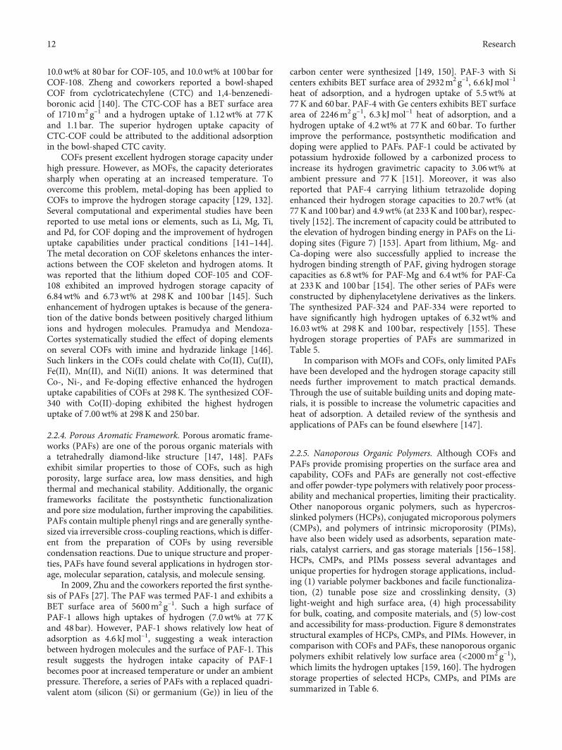

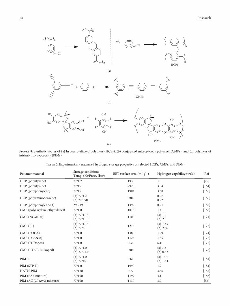


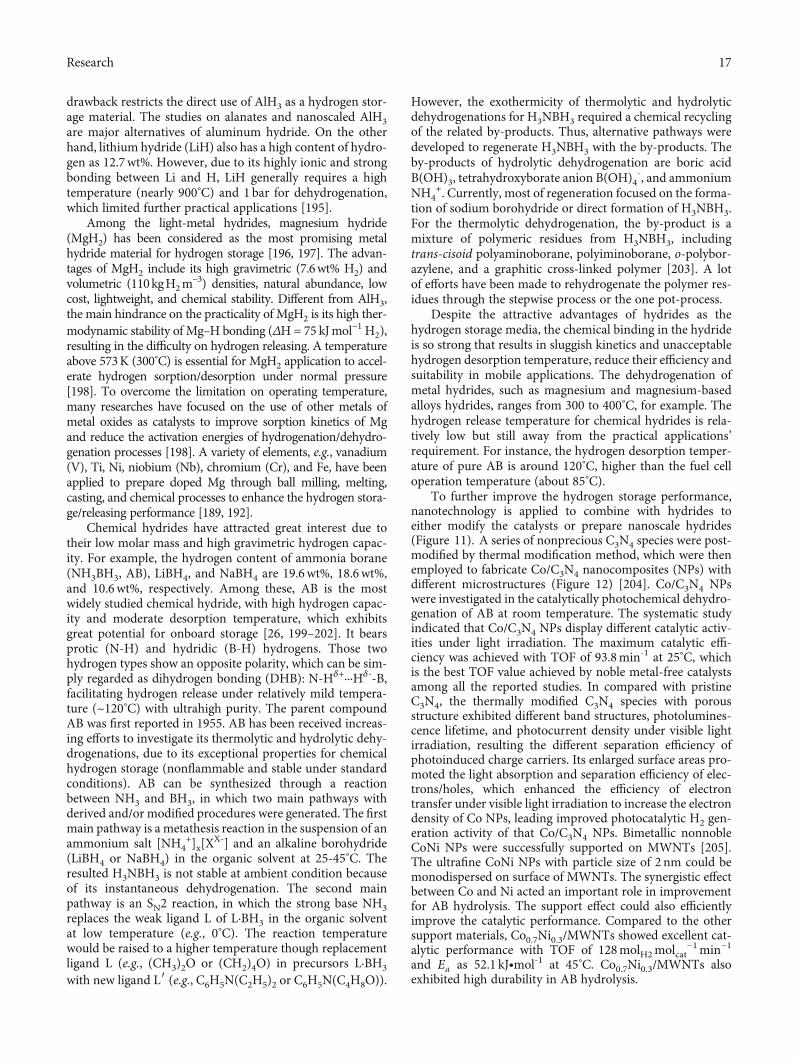


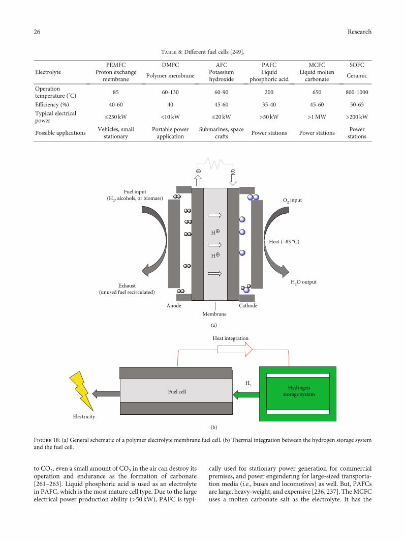


![HDAAR 7367828 1.downloads.spj.sciencemag.org/research/2019/7367828.pdf · burgeoning field of nanoenergy [5, 6]. There are many forms of energy sources that can be collected and](https://static.documents.pub/doc/80x56/5f647d62c07b635d9b7e0f2d/hdaar-7367828-1-burgeoning-ield-of-nanoenergy-5-6-there-are-many-forms-of.jpg)
![HDAAR 2384347 1.downloads.spj.sciencemag.org/research/2019/2384347.pdf · rials, polymeric hydrogel actuators [6–10] could produce reversible shape transformation in response to](https://static.documents.pub/doc/80x56/5e8db26ff8f35b590d65d0ad/hdaar-2384347-1-rials-polymeric-hydrogel-actuators-6a10-could-produce-reversible.jpg)


![HDAAR 8748602 1. · 2020. 11. 19. · optical properties [1, 2]. More recently, the potential of 2D materialsforsensing hasbeenfurther extendedbyfreely sus-pending 2D materials to](https://static.documents.pub/doc/80x56/60d0deab8ebaf60f8b58f79d/hdaar-8748602-1-2020-11-19-optical-properties-1-2-more-recently-the-potential.jpg)

![HDAAR 7236946 1. - Science · 2020. 5. 9. · PS A C Ti Si Tini 316 Gass PVC E PU PS D-ting Coate te 1336.8 [+H] + N H N H H H H H 200 400 600 800 1000 1200 m/z Relative ndance Intensit](https://static.documents.pub/doc/80x56/60ff70be6898b61f8840eae9/hdaar-7236946-1-science-2020-5-9-ps-a-c-ti-si-tini-316-gass-pvc-e-pu-ps.jpg)


![HDAAR 7286735 1. - Science...2020/05/28 · ratory virus is best exemplified by studies of the Respiratory Syncytial Virus (RSV) [22, 23]. The spread of SARS-CoV-2 via fomites has](https://static.documents.pub/doc/80x56/60e7b40f5811aa25125a5e6f/hdaar-7286735-1-science-20200528-ratory-virus-is-best-exempliied-by.jpg)


