Research ArticleMg-Based Micromotors with Motion Responsive to Dual Stimuli
Kang Xiong , Leilei Xu , Jinwei Lin , Fangzhi Mou , and Jianguo Guan
State Key Laboratory of Advanced Technology for Materials Synthesis and Processing, International School of Materials Scienceand Engineering, Wuhan University of Technology, Wuhan 430070, China
Mg-based micromotors have emerged as an extremely attractive artificial micro/nanodevice, but suffered from uncontrollablepropulsion and limited motion lifetime, restricting the fulfillment of complex tasks. Here, we have demonstrated Mg-basedmicromotors composed of Mg microspheres asymmetrically coated with Pt and temperature-sensitive poly(N-isopropylacrylamide)(PNIPAM) hydrogel layers in sequence. They can implement different motion behaviors stemming from the drivingmechanism transformation when encountering catalyzed substrates such as H2O2 and respond to both H2O2 concentrationand temperature in aqueous environment. The as-constructed Mg-based micromotors are self-propelled by Pt-catalyzedH2O2 decomposition following the self-consuming Mg-H2O reaction. In this case, they could further generate bilateralbubbles and thus demonstrate unique self-limitation motion like hovering when the phase transformation of PNIPAM istriggered by decreasing temperature or when the H2O2 concentration after permeating across the PNIPAM hydrogel layer ishigh enough to facilitate bubble nucleation. Our work for the first time provides a stimuli-induced “hovering” strategy forself-propelled micromotors, which endows Mg-based micromotors with an intelligent response to the surroundings besidesthe significant extension of their motion lifetime.
1. Introduction
Inspired by microorganisms in nature, artificial micromotorsthat propel themselves by converting diverse energies havebeen designed to perform complex tasks, such as cargotransport [1–3], advanced nanomanufacturing [4, 5], andenvironment remediation in microscopic environments[6–11]. Their motile behavior also further endows themgreat advantages as next-generation nanorobotics used forbiomedicine [12, 13].
Mg-based micromotors, as a typical class of self-consuming artificial micromotors, not only could be pow-erfully driven by the Mg-H2O reaction in physiologicalcondition but also produce a byproduct of Mg2+ ions, anadditional nutritional ingredient that benefits the humanbodies [14, 15]. Additionally, the vast quantities of therapeu-tic hydrogen generated in the propulsion can further be usedto eliminate excessive hydroxyl radicals which are harmful toliving bodies [16]. They displayed superior compatibility forbiological systems and have already been applied for drugdelivery in the gastrointestinal tract of mice with enhancedtherapeutic efficacies [17–22]. However, they generally suffer
from poor motion controllability and relatively short motionlifetime stemming from the single driving reaction and self-consuming feature and cannot stop their movement unlessthe solid “fuel” Mg cores are almost consumed [23, 24]. Toprolong the lifetime and improve the motion controllabilityof Mg-based micromotors, several strategies have so far beendeveloped including tuning the opening size, controlling thepitting anions, and being functionalized with photocata-lysts [21, 25], soft hydrogels [26], or biological materials[19, 25, 27, 28]. Yet they still face challenges in stimuli-responding propulsion and desirable “on/off” characteristics,and further efforts are necessary toward intelligence andcontrollability, which may lay the foundation for Mg-basedmicromotors to fulfill tasks in complex environments.
Here, we present a Mg-based micromotor with motionresponsive to both H2O2 concentration and temperature inthe surroundings. It consists of a Mg microsphere asymmet-rically coated with Pt and temperature-sensitive poly(N-iso-propylacrylamide) (PNIPAM) hydrogel layers in sequence.It can demonstrate the propulsion mechanism transforma-tion between Mg-H2O reaction and Pt-catalyzed H2O2decomposition and unique concentration- or temperature-
AAASResearchVolume 2020, Article ID 6213981, 12 pageshttps://doi.org/10.34133/2020/6213981
induced self-limitation behaviors like hovering. Thetemperature-induced volume phase transformation (swel-ling/shrinking) of PNIPAM and the H2O2 concentrationboth affect the permeability of H2O2 into the hydrogel layerand thus make the generation of O2 bubbles in either singleor bilateral sides, resulting in self-limitation motion. Thiswork presents a stimuli-induced “hovering” strategy for themanipulation of Mg-based micromotors as well as a methodfor prolonging their lifetime by taking use of fuels from thesurroundings. Given the possible changes of H2O2 concen-tration and temperature in human bodies, especially in dis-eased sites, the herein reported dual stimuli-responsivenessof Mg-based micromotors with extended motion lifetimemay to some extent promise potential advanced biomedicalapplications.
2. Results and Discussion
Given the motion environment diversity of micromotorswhen used, we focus on the changes of chemical reactionpropulsion mechanism and dual stimuli-responsive motionbehaviors of Mg-based micromotors in the liquid environ-ment system. The aim is to achieve their long-term lifetimeand motion manipulation. In view of the popularity of tem-perature difference and low concentration H2O2 in eitherbiological or environmental system, we have integrated Mg
microspheres with catalytically active Pt to H2O2 andtemperature-responsive poly(N-isopropylacrylamide) (PNI-PAM) hydrogels to construct Mg-based micromotors. Theywere fabricated by asymmetrically coating Mg microsphereswith Pt and PNIPAM hydrogel layers in sequence viamagnetron sputtering and UV polymerization techniquesaccording to our previous literature [29]. The as-fabricatedMg-based micromotors are about 40μm in size and exhibit“opening” of about 14μm of the surface (Figures S1 andS2). As shown in Figure 1, the Mg-based micromotor whenoperated in an aqueous solution (e.g., containing NaHCO3and poly(vinylpyrrolidone) (PVP)) is driven by asymmetricalH2 bubble release generated by Mg-H2O reaction due to theeffective shielding of Pt layer from water in a graduallyincreasing confined space. When encountering catalyzedsubstrates such as H2O2, the propulsion mechanism of theMg-based micromotor will transform spontaneously fromthe self-consuming Mg-H2O reaction into Pt-catalyzed H2O2decomposition. As H2O2 (HO2
− +H2O + 2e− ⟶ 3OH−,E0 = 0:878V vs. SHE) has a stronger oxidization ability thanH2O (2H2O + 2e− ⟶H2 + 2OH−, E0 = −0:83V vs. SHE)[30], the reaction of Mg and H2O2 is much easier to occurthan the Mg-H2O reaction. As a result, O2 bubbles fromPt-catalyzed H2O2 decomposition instead of H2 bubblespropel the micromotor and the motion lifetime could beprolonged due to the transformation of driving reactions
Mg + 2H2O → Mg (OH) 2 + H2 2H2O2 → 2H2O + O2
Pt
(I)
Pt
No H2O2 H2O2 concentration
PNIPAM
(II)Mg
Driving mechanismtransformation
LCSTT
0
Concentration-inducedself-limitation
(III)
Tem
pera
ture
-indu
ced
self-
limita
tion
O2 bubbles
H2 bubblesPt
Mg
Swelling PNIPAM
Shrinking PNIPAM
Figure 1: Schematic illustration of the Mg-based micromotor showing motion responsiveness to dual stimuli of temperature and H2O2concentration. (I) The driving mechanism of the Mg-based micromotor is transformed from self-consuming Mg-H2O reaction to Pt-catalyzed H2O2 decomposition once H2O2 appears in the solution. (II) Temperature-induced volume phase transformation of PNIPAMinduces the transformation of motion behaviors. When temperature is lower than LCST, the covered PNIPAM hydrogel layer swells toincrease the amount of permeated H2O2 and thus the catalytically generated oxygen on the side of the PNIPAM hydrogel layer, resultingin a self-limitation motion of the Mg-based micromotor like hovering due to bubble O2 recoils from bilateral sides. (III) Concentrationgradient of H2O2 induces the transformation of motion behaviors. Increasing H2O2 concentration raises the H2O2 concentration gradientbetween the two sides of the hydrogel layer, which facilitates H2O2 to cross the PNIPAM hydrogel layer and react with the middle Pt layerto form O2 bubbles. Consequently, a self-limitation behavior of the Mg-based micromotor occurs due to bilateral O2 bubble generation.
2 Research
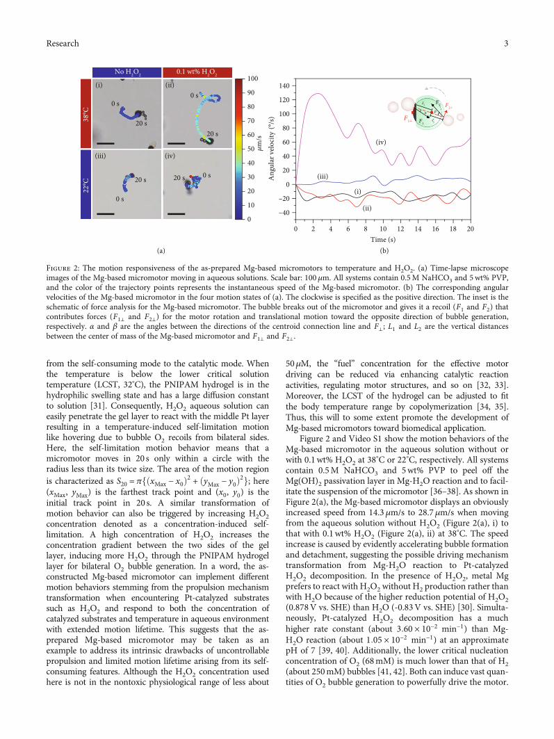
from the self-consuming mode to the catalytic mode. Whenthe temperature is below the lower critical solutiontemperature (LCST, 32°C), the PNIPAM hydrogel is in thehydrophilic swelling state and has a large diffusion constantto solution [31]. Consequently, H2O2 aqueous solution caneasily penetrate the gel layer to react with the middle Pt layerresulting in a temperature-induced self-limitation motionlike hovering due to bubble O2 recoils from bilateral sides.Here, the self-limitation motion behavior means that amicromotor moves in 20 s only within a circle with theradius less than its twice size. The area of the motion regionis characterized as S20 = πfðxMax − x0Þ2 + ðyMax − y0Þ2g; here(xMax, yMax) is the farthest track point and (x0, y0) is theinitial track point in 20 s. A similar transformation ofmotion behavior can also be triggered by increasing H2O2concentration denoted as a concentration-induced self-limitation. A high concentration of H2O2 increases theconcentration gradient between the two sides of the gellayer, inducing more H2O2 through the PNIPAM hydrogellayer for bilateral O2 bubble generation. In a word, the as-constructed Mg-based micromotor can implement differentmotion behaviors stemming from the propulsion mechanismtransformation when encountering Pt-catalyzed substratessuch as H2O2 and respond to both the concentration ofcatalyzed substrates and temperature in aqueous environmentwith extended motion lifetime. This suggests that the as-prepared Mg-based micromotor may be taken as anexample to address its intrinsic drawbacks of uncontrollablepropulsion and limited motion lifetime arising from its self-consuming features. Although the H2O2 concentration usedhere is not in the nontoxic physiological range of less about
50μM, the “fuel” concentration for the effective motordriving can be reduced via enhancing catalytic reactionactivities, regulating motor structures, and so on [32, 33].Moreover, the LCST of the hydrogel can be adjusted to fitthe body temperature range by copolymerization [34, 35].Thus, this will to some extent promote the development ofMg-based micromotors toward biomedical application.
Figure 2 and Video S1 show the motion behaviors of theMg-based micromotor in the aqueous solution without orwith 0.1wt% H2O2 at 38
°C or 22°C, respectively. All systemscontain 0.5M NaHCO3 and 5wt% PVP to peel off theMg(OH)2 passivation layer in Mg-H2O reaction and to facil-itate the suspension of the micromotor [36–38]. As shown inFigure 2(a), the Mg-based micromotor displays an obviouslyincreased speed from 14.3μm/s to 28.7μm/s when movingfrom the aqueous solution without H2O2 (Figure 2(a), i) tothat with 0.1wt% H2O2 (Figure 2(a), ii) at 38
°C. The speedincrease is caused by evidently accelerating bubble formationand detachment, suggesting the possible driving mechanismtransformation from Mg-H2O reaction to Pt-catalyzedH2O2 decomposition. In the presence of H2O2, metal Mgprefers to react with H2O2 without H2 production rather thanwith H2O because of the higher reduction potential of H2O2(0.878V vs. SHE) than H2O (-0.83V vs. SHE) [30]. Simulta-neously, Pt-catalyzed H2O2 decomposition has a muchhigher rate constant (about 3:60 × 10−2 min−1) than Mg-H2O reaction (about 1:05 × 10−2 min−1) at an approximatepH of 7 [39, 40]. Additionally, the lower critical nucleationconcentration of O2 (68mM) is much lower than that of H2(about 250mM) bubbles [41, 42]. Both can induce vast quan-tities of O2 bubble generation to powerfully drive the motor.
0 s
20 s
0 s
20 s 20 s 0 s
(i) (ii)
(iii) (iv)
(a) (b)
(ii)
(i)
(iv)
(iii)
0–40
0 2 4 6 8 10Time (s)
12 14 16 18 20
–20
0
20
40
60
80
100
Ang
ular
vel
ocity
𝜇m
/s
120
140100
90
80
70
60
50
40
30
20
10
No H2O2 0.1 wt% H2O2
20 s
0 s
F1⊥
F2⊥F2
L2
L1
F1
𝛼 𝛽
Figure 2: The motion responsiveness of the as-prepared Mg-based micromotors to temperature and H2O2. (a) Time-lapse microscopeimages of the Mg-based micromotor moving in aqueous solutions. Scale bar: 100μm. All systems contain 0.5M NaHCO3 and 5wt% PVP,and the color of the trajectory points represents the instantaneous speed of the Mg-based micromotor. (b) The corresponding angularvelocities of the Mg-based micromotor in the four motion states of (a). The clockwise is specified as the positive direction. The inset is theschematic of force analysis for the Mg-based micromotor. The bubble breaks out of the micromotor and gives it a recoil (F1 and F2) thatcontributes forces (F1⊥ and F2⊥) for the motor rotation and translational motion toward the opposite direction of bubble generation,respectively. α and β are the angles between the directions of the centroid connection line and F⊥; L1 and L2 are the vertical distancesbetween the center of mass of the Mg-based micromotor and F1⊥ and F2⊥.
3Research
As the PNIPAM hydrogel is a temperature-responsivepolymer with LCST, it usually exhibits a sharp volume phasetransition at LCST, which is slowed by further increasing/decreasing temperature [43]. On the basis of the swelling-shrinking kinetics of the PNIPAM hydrogel, the collectivediffusion coefficient for swelling (D0 = 2:0 × 10−7 cm2 s−1) isabout twice than that for shrinking (D0 = 1:1 × 10⁻⁷ cm2 s−1)[44, 45]. Although at the temperature below the LCST(32°C) the PNIPAM has a volume swelling with a large coop-erative (collective) diffusion of the gel network [31, 44], themicromotor can only be propelled by asymmetrical bubblerecoils during the Mg-H2O reaction because of the effectiveblocking from water by the middle Pt layer (Figure 2(a), iand iii). This will change when H2O2 appears in the system.As shown in Figure 2(a), iv, the micromotor shows anenhanced rotation with a decreased speed of about 15.8μm/sand a decreased S20, which looks like hovering because of bilat-eral bubble generation and release. This can be explained bythe assumption that H2O2 aqueous solutionmay diffuse acrossthe swelling hydrogel layer, reacting with the middle Pt layerto induce a self-limitation motion behavior of the Mg-basedmicromotor.
In order to explicate the temperature-induced self-limitation behavior, the corresponding angular velocitycurves of Figure 2(a) are given in Figure 2(b). The single-side bubble-propelled micromotors (i, ii, and iii) show simi-lar angular velocity curves with placid angular changes, whilethe bilateral-side bubble-propelled micromotor shows a rela-tively large angular change (iv). This can well explain theoriginality of the observed self-limitation state of the micro-motor shown in Figure 2(a), iv. Under low Reynolds num-ber conditions, the inertial effect can be neglected. Themotion of the as-prepared Mg-based micromotor can bedescribed by a set of differential equations for translationand rotation [46–48]:
mdvdt
= FStokes + FBrownian + Fdrive,
Jdωdt
= TStokes + TBrownian + Tdrive,ð1Þ
where m represents the mass of the motor, J is the inertiatensor, and v and ω denote the translation velocity andangular velocity. The terms that distinguish these Langevinequations from standard Langevin equations for inactiveBrownian particles are the driving force and torquecontributions arising from bubble detachment. Thereinto,FBrownian and TBrownian represent the diffusion arising fromthe Brownian force and torque with zero mean. Thepurely Brownian force for a passive particle can bedescribed by a theoretical translational diffusion coefficient(DT = kBT/6πηR) [49] and a rotational diffusion coefficient(τ−1R = kBT/8πηR3) [50]. In this system, as a spherical par-ticle with a radius about 40μm, the characteristic timescale for rotational diffusion τR and translational diffusioncoefficient DT is calculated to be 728.5min and 1:22 ×10−10 cm2/s, respectively. This means the effect of Brow-nian force on the motion of the as-prepared micromotor
is limited. Fdrive and Tdrive are the reaction force and tor-que caused by the detachment of the bubbles, which willbe balanced by the Stokes viscous drag force generatedin the opposite direction during motion. Because of thespherical structure of the as-prepared micromotor, FStokes =6πηRv (for translation) and TStokes = 8πηR3ω, where R is theparticle (hydrodynamic) radius and η is the fluid viscosity.For the motion of the as-prepared Mg-based micromotor,the contributions of FStokes and TStokes are passive dependingon v and ω and the rotation of bubble recoil-propelled micro-motors mainly arises from the bubble detachment deviatingfrom their symmetry [26, 51–53]. Therefore, a simplified forceanalysis of a micromotor based on the driving force is used tounderstand the motion states. F1 and F2 represent the instantpropulsion forces provided by the bubble detachment fromthe opening and the coated side, respectively. For the casesshown in Figure 2(a), i, ii, and iii, F2 = 0 and the micromotoris only driven by single-side bubble recoil on the opening.Their rotational motions are all caused by the rotationalcomponent of F1 contributing an instant torque expressed asT1 = F1⊥L1 = F1L1 sin α, where F1⊥ represents the verticalcomponent of F1 for motor rotation, L1 is the effective leverarm, and α is the angle between the directions of the centroidconnection line and F1⊥. The differences in their motion statesincluding translational and rotational velocities as well asrotational directions mainly depend on α and the bubbledetachment positions. For the micromotor moving in0.1wt% H2O2 aqueous solution at 22°C, neither F1 nor F2 is0 due to bilateral bubble generation and ejection. As a result,the instantaneous torque that contributed to the micromo-tor’s rotation is the vector sum of the two torques: T1 ðT1 =F1L1 sin αÞ generated by bubble escape from the open endand T2 ðT2 = F2L2 sin βÞ generated by bubble release fromthe coating side. When αβ > 0, the micromotor exhibits anenhanced rotation corresponding to a large angular velocity(Figure 2(b), iv), while it shows a weakened rotation asαβ < 0 (Figure S3, Video S2). The self-limitation behavior ofthe Mg-based micromotor in the H2O2 aqueous solutionbelow the LCST of PNIPAM is attributed to the enhancedrotation caused by the bilateral-side bubble detachments.
The dissolved H2 and O2 in the aqueous solution beforeand after adding H2O2 are determined to verify the drivingmechanism transformation from the self-consuming Mg-H2O reaction to the Pt-catalyzed H2O2 decomposition.Figure 3 shows that when the motors move in the aqueoussolution without H2O2, the dissolved H2 in the solutionincreases gradually. This indicates that the driving reactionat this moment is a H2-produced reaction as Mg +H2O +2HCO−
3⇌MgCO3 + CO2−3 + 2H2. When H2O2 is introduced
into the solution at 301 s, the dissolved H2 drops sharply,while the dissolved O2 rises from 2.7mg/L to 19.9mg/L.This implies that the driving reaction of the Mg-basedmicromotors is transformed to Pt-catalyzed H2O2 decom-position (producing O2) instead of the Mg-H2O reaction(producing H2). The initial O2 concentration in the aque-ous solution stems from dissolved air. This transformationarises from the strong oxidization of H2O2 with a muchhigher electrode potential than that of H2O [30]. In the
4 Research
presence of H2O2, Mg prefers to react with H2O2 withoutgenerating H2 rather than to react with H2O [54] andsimultaneously Pt-catalyzed H2O2 decomposition can pro-duce O2 gas. This can be further verified by the fact thatno bubble generates when bare Mg microparticles are putin H2O2 aqueous solution (Video S3).
As discussed above, the Mg-based micromotor can bedriven by both Mg-H2O reaction in the aqueous solutionwithout H2O2 and Pt-catalyzed H2O2 decomposition whenmeeting H2O2. In the aqueous solution containing NaHCO3and PVP but without H2O2, the Mg core is consumed contin-uously via the Mg-H2O reaction to produce numerous H2bubbles that propel the micromotor due to the conservationof momentum [55]. Figure 4 shows the Mg core amountsand motion speeds versus time, respectively. After overcom-ing the initial gravity-induced subsidence (Figure S4 andVideo S4), the micromotor keeps moving by bubble recoilswith the Mg core amount continuously decreasing asshown in Figure 4(a) and Video S5, indicating its self-consumed feature. At this time, the lifetime of themicromotor mainly depends on the opening size (Figure S5)and is in the range of a few minutes to dozens of minutes.With the Mg-H2O reaction proceeding, there forms aconfined space inside the micromotor, where the nucleationand growth of H2 bubbles occur. At the early stages, theejected bubbles are small, while they become large when theMg core is almost gone. The size of the formed bubbles ismainly dependent on the growth time in the confined space.At the initial stages, the narrow space between the Mg coreand the coating layer is too narrow for the growth of bubblesbefore they eject from the micromotor due to the capillaryeffect. Upon the enlarged confined space over time, thegrowth period is extended resulting in the formation of largebubbles. Figure 4(b) shows that the as-prepared micromotorhas a relatively constant motion speed and consumption rateof the Mg core during Mg-H2O reaction. This is not inagreement with the previous reported surface area-relatedreaction rate and can be explained by the effect of the
confined space, in which the permeation of water iscompetitive with the escape of bubbles.
The as-constructed Mg-based micromotors can improvethe motion controllability and lifetime by the spontaneoustransformation of propulsion mechanisms from the self-consuming reaction to the catalytic reaction in terms of thesurroundings. In H2O2 aqueous solution, the as-preparedMg-based micromotor can be driven by Pt-catalyzed H2O2decomposition and keeps constantly moving until the fuel(H2O2) runs out. The lifetime of the motor moving inH2O2 aqueous solution is determined by the amount ofH2O2 and has been significantly prolonged because of thefar excess “fuel” in the system. Figure 5 shows the effect ofH2O2 concentration on the motion behaviors of the Mg-based micromotors. Taking a micromotor moving at 38°Cfor example, the as-prepared micromotor first acceleratesand then decelerates the motion with increasing the H2O2concentration (Figure 5(a)). This is dramatically differentfrom the previously reported catalytic micromotors, whosespeeds generally increase with increasing catalytic substrateconcentrations [56–58]. The speeds of the Mg-basedmicromotor before and after the addition of H2O2 withdifferent concentrations are shown in Figure S6. When themicromotor moves in the solution without H2O2, themotion speed is basically stable with an average value ofabout 13.2μm/s depending on the relatively constant H2bubble size and generation frequency (Video S5). Afteradding H2O2, the motion speeds of the micromotorcontributed by O2 detachment from Pt-catalyzed H2O2decomposition are closely related to H2O2 concentration.The initial increase of the speed with increasing H2O2concentration (0~0.4wt%) is attributed to an increasedbubble generation frequency. The large variability of speedin 0.4wt% H2O2 aqueous solution may be attributed to therapid changes of α and the bubble escape positions inmotion (Video S6). The remarkable decrease of motionspeed occurs as the H2O2 concentration is further increasedto 0.8wt%, implying a possible change of motion behavior.As shown in Figure 5(b) and Video S7, the micromotordisplays a self-limitation motion like hovering due to thebilateral O2 bubble generation and release as H2O2concentration is higher than 0.8wt%. This indirectlyreduces the asymmetry of the micromotor and leads to thereduction of the speed. After diluting 0.8wt% H2O2aqueous solution to 0.67wt%, the micromotor shows acurved ballistic trajectory as the O2 bubbles are releasedfrom the opening instead of bilateral release, while thebilateral O2 bubble generation and detachment occuragain after supplementing H2O2 to 1.23wt%. In otherwords, the as-prepared micromotor exhibits a self-limitation behavior in a relatively high-concentrationH2O2 aqueous solution and returns to a curved ballisticmotion at a low concentration. The transformation isreversible with changing the concentration of H2O2. Suchunique concentration-induced self-limitation is associatedwith the permeability of H2O2 into the PNIPAM hydrogellayer. A high concentration of H2O2 aqueous solution canform a large concentration gradient between the two sidesof the hydrogel layer to facilitate more H2O2 across the
0.0
0 100 200 300Time (s)
400 500
0
4
8
12
16
200.1 wt% H2O2No H2O2
0.1
0.2
Diss
olve
d H
2 (mg/
L)
Diss
olve
d O
2 (mg/
L)
0.3
0.4
Figure 3: The diagram of dissolved H2 and O2 over time before andafter adding H2O2 in the motion system containing 0.5M NaHCO3and 5wt% PVP.
5Research
PNIPAM hydrogel layer and react with the middle Pt layer.As a result, the generated O2 accumulates and reaches theheterogeneous nucleation energy on the side of thehydrogel layer for O2 bubble nucleation and growth,resulting in a concentration-induced self-limitation.
To further illustrate the temperature/concentration-dependent self-limitation motion mechanisms of the Mg-based micromotor driven by Pt-catalyzed H2O2 decomposi-tion, we have carried out numerical simulations over theMg-based micromotor based on a 2D model (Figure S7) bychemical reaction engineering and dilute chemical speciestransport modules of COMSOL Multiphysics. Figure 6
shows the numerical simulation results of O2 concentrationdistribution around the Mg-based micromotor withdifferent temperatures and H2O2 concentrations. It shouldbe noted that the simplified model only considers the O2concentration distribution for nucleation and ignores thefluid disturbance deriving from micromotor motion. Inthis model, the PNIPAM coating is treated as a porousmedia, because the swelling/shrinking of the hydrogelnetwork can result in different porosities for O2 diffusion,which is temperature-dependent. In a swelling state, a largecooperative diffusion coefficient benefits the permeation ofH2O2 through the hydrogel layer resulting in a network
(a) (b)
20.02 𝜇m
0 s 120 s
240 s 360 s
23.28 𝜇m25.44 𝜇m
17.16 μm 0
0 50 100 150 200 250 300 350 400 4500
1
2
3
4
5
6
7
20
40
60
80
100
120
Ave
rage
spee
d (𝜇
m/s
)
140
Time (s)
Figure 4: The Mg-based micromotor propelled by the Mg-H2O reaction. (a) Time-lapse microscope images of Mg core consumption in thesolution without H2O2. (b) The corresponding average speeds in every 40 s of the Mg-based micromotor and Mg core amounts versus time.The red line indicates the fitting line for Mg core consumption.
Figure 5: The effect of H2O2 concentration on motion behaviors of the Mg-based micromotor. (a) The average speed of the Mg-basedmicromotor in a solution with different concentrations of H2O2 at 38°C. The black line represents the trend line. (b) The H2O2concentration of the aqueous solution containing the Mg-based micromotor versus time. The insets show typical states of the micromotorin each period, and the dotted line represents a transitional period after which a constant local H2O2 concentration is available in thesystem. Scale bar: 100μm. In the aqueous solution without H2O2 (0~250 s), bubbles generate from the open end of the Mg-basedmicromotor, while adding H2O2 to raise the concentration to 0.8 wt% results in bilateral bubble production (250~480 s). Further reducingH2O2 concentration to 0.67wt% via diluting makes the reaction occur in a unilateral side (480~820 s), and the reaction again occurs inbilateral sides when the concentration reaches 1.23wt% by adding H2O2 again (820~1100 s).
6 Research
with large porosity, which is approximately twice than thatin a shrinking state [44, 59]. When the micromotor ismoving below the LCST at a low-concentration H2O2aqueous solution of 0.1wt%, the O2 generated inside the
coating layer will reach the critical nucleation concentrationof 68mM within 1ms due to the accumulative effect of theinner confined void (Figure 6(a)). Simultaneously, in view ofthe water-swelling feature of the PNIPAM hydrogel layer at
0
100
200
300
400
500
600
700
800
0102030405060708090
100
–50 –40 –30 –20 –10 0 10 20 30 40 500
102030405060708090
100
PNIPAM
68 mM
68 mM
Mg
InsideOutside
PNIPAM Pt
0 ms
20 ms
A A′
A′A
Pt
A A'
Pt
68 mM
Mg
InsideOutside
PNIPAM Pt
0 ms
20 ms
Mg
InsideOutside
PNIPAM Pt
0 ms
20 ms
PNIPAM
PNIPAM
Pt Mg
Mg
Mg
0
0.1
0.2
0.3
0.4
0.5
0.6
0.7
0.8
0.9
1
0
0.1
0.2
0.3
0.4
0.5
0.6
0.7
0.8
0.9
1
0
0.1
0.2
0.3
0.4
0.5
0.6
0.7
0.8
0.9
1
–40
–40 –20 0 20 40
–35–30–25–20–15–10
–505
101520253035
(𝜇m)
(𝜇m
)
–40
–40 –20 0 20 40
–35–30–25–20–15–10
–505
101520253035
(𝜇m)
(𝜇m
)
–40
–40 –20 0 20 40
–35–30–25–20–15–10
–505
101520253035
(𝜇m)
(𝜇m
)
O2 co
ncen
trat
ion
(mM
)O
2 conc
entr
atio
n (m
M)
O2 co
ncen
trat
ion
(mM
)
Distance (𝜇m)
(a)
(b)
(c)
–50 –40 –30 –20 –10 0 10 20 30 40 50Distance (𝜇m)
–50 –40 –30 –20 –10 0 10 20 30 40 50Distance (𝜇m)
Figure 6: The normalized O2 concentration distribution around the Mg-based micromotor at (a) 22°C in 0.1 wt% H2O2, (b) 38°C in 0.1 wt%
H2O2, and (c) 38°C in 0.8 wt%H2O2 aqueous solution. The right panels show the curves of theoretical O2 concentration on AA′ line segments
within 20ms versus the distance apart from the center of Mg core at different time intervals. The critical nucleation concentration of O2bubble is 68mM.
7Research
this temperature, there are more H2O2 permeating acrossthe hydrogel layer to react with the middle Pt layerresulting in O2 nucleation on the side of the hydrogellayer. As a result, the micromotor shows a self-limitationbehavior caused by bilateral O2 bubble generation(Figure 2(a), iv). In contrast, by increasing temperature to38°C, the access of H2O2 is slowed down by the contractedPNIPAM hydrogel layer. Consequently, the concentration ofO2 generated on the side of the hydrogel layer cannot reachits critical nucleation concentration under continuousoutward diffusion (Figure 6(b)). Therefore, the insidegenerated O2 bubble detachment from the opening is theorigin of the sufficient propulsion of the as-prepared Mg-based micromotor (Figure 2(a), ii). However, increasingthe H2O2 concentration to 0.8wt% could facilitate thepermeation of H2O2 aqueous solution into the PNIPAMhydrogel layer and the catalytic decomposition of H2O2 atthe middle layer Pt (Figure 6(a)). This enables the O2generation on both sides of the middle Pt layer to reachthe critical nucleation concentrations and thus induce self-limitation motion of the micromotor.
3. Conclusion
In this work, we present a kind of dual mechanism-propelledMg-based micromotor with motion responsive to bothtemperature and H2O2 concentration. The as-constructedMg-based micromotors are obtained by asymmetrically coat-ing of Mg microspheres with catalytically active Pt andtemperature-sensitive PNIPAM hydrogel layers in sequence.They can be propelled by Mg-H2O reactions followed by Pt-catalyzed H2O2 decomposition when encountering H2O2and exhibit extended motion lifetime. In the latter case,they would respond to both H2O2 concentration and tem-perature in solution environment, demonstrating uniquetemperature- and/or concentration-induced self-limitationmotion like hovering. This is associated with the temperature-dependent diffusion coefficient and the concentration-relatedpermeability of H2O2 aqueous solution in the PNIPAM hydro-gel layer. Our results have for the first time demonstrated theMg-based micromotors with motion responsive to externalstimuli in a multifuel system and provided a strategy to pushforward the development of intelligent Mg-based micromotorsand to prolong the motion lifetime.
4. Materials and Methods
4.1. Materials. All the chemicals used in this work were ofanalytical grade and were used as received without furtherpurification. Poly(vinylpyrrolidone) (PVP, K30), ethyleneglycol (EG), hydrogen peroxide, N-isopropylacrylamide(NIPAM), bis(N,N-methylene bis(acrylamide)), 2,2-diethox-yacetophenone (DEAP), sodium bicarbonate (NaHCO3),acetone, and ethanol were purchased from TCI (Shanghai)Development Co., Ltd., China. Commercial Mg micro-spheres were purchased from TangShan WeiHao Magne-sium Powder Co. (Tangshan, China) and washed withacetone twice before usage.
4.2. Fabrication of the Mg-Based Micromotors. The Mg-basedmicromotors are prepared by our previously reportedmethod with some modifications [29] shown in Figure S1.In detail, Mg microspheres with an average size of about40μm were completely scattered on the surface of a glassslide precoated with a thin poly(vinylpyrrolidone) (PVP,K30) film by dripping 100μL 0.5wt% PVP ethanol solutionon the glass slide and then drying at 60°C for 10min. Then,the PVP-glass slide with dispersed Mg microspheres wasplaced in humid air with a relative humidity of 50% for20 s. During this process, Mg microspheres were partiallyimmersed in the PVP film under the gravitational fieldto obtain partially covered carriers. After drying in anoven at 60°C for 10min, the Mg microspheres withpartially covered bottom surface were fixed in the PVPfilm. Then, the exposed Mg surfaces were coated with aPt layer via magnetron sputtering for 240 s to obtain theMg/Pt microspheres fixed. The poly(N-isopropylacrylamide)(PNIPAM) precursor solution was prepared by dissolving0.35g NIPAM in 3.5mL EG followed by adding 0.2gbis(N,N-methylene bis(acrylamide)) and 20μL 2,2-DEAP intothe solution. Subsequently, 100μL PNIPAM-EG precursorsolution was dropped onto the obtained glass slide to form aliquid film on the surface of the Mg/Pt microspheres fixed onthe PVP-glass slide followed by spin-coating by a spin coater(speed of 2000 rpm, coating time of 50 s, EZ4 spin coater,Schwan Technology) and then covered by a slip. The obtainedglass slide was exposed to the UV light to polymerize NIPAMfor 240 s followed with removing the thin cover slips anddrying in vacuum at 60°C for 12h. Finally, the Mg-basedmicromotors were separated from the substrate by a blade-scratching process and washed with acetone twice to removethe PVP layer.
4.3. Motion Tests of the Mg-Based Micromotors. The move-ment of the as-prepared Mg-based micromotors wasperformed in 0.5M NaHCO3 aqueous solution with 5wt%PVP as surfactant. In each test, 90μL 0.5M NaHCO3 and5wt% PVP containing the micromotors were dispersed ona glass slide. The glass slide was heated from room tempera-ture to the desired temperature using the microscope temper-ature control stage. Then, 10μL H2O2 aqueous solution withdifferent concentrations was dropped on the glass slide forobservation and recorded with an optical microscope usinga high-resolution CCD digital camera (Leica DM 3000B,Inc. Germany).
4.4. Determination of Dissolved H2 and O2. To measure dis-solved O2 and dissolved H2 in the system, 20mg Mg-basedmicromotors was added into 90mL 0.5M NaHCO3 and5wt% PVP solution at 22°C. After 301 s, 10mL 1wt% H2O2was added into the system. During the whole process, thedata was measured and recorded by the portable dissolvedH2 and O2 analyzers.
4.5. Characterizations. Scanning electron microscopy (SEM)images were taken with a Hitachi S-4800 (Japan) at anacceleration voltage of 10.0 kV. The energy dispersivespectroscopy (EDS) analyses were carried out on a JEOL
8 Research
JEM-7500F (Tokyo, Japan) operated at an accelerating volt-age of 15 kV. Magnetron Sputtering System (JCP500, BeijingTechnol Science Co., Ltd., China) was used to cover the mid-dle Pt layer. The microscopy images and the motion videos ofmicromotors were recorded with optical microscope using ahigh-resolution CCD digital camera (Leica DM 3000B, Inc.Germany) coupled with ×5, ×10, ×20, and ×40 objective.The temperature was heated by heating accessories (Temp-Controller 2000-1, Inc. Germany) of the microscope. Allvideos were analyzed by Video Spot Tracker V08.01 andMatlab R2018a software.
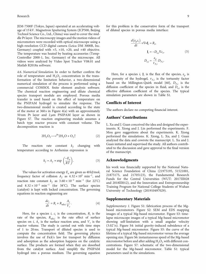
4.6. Numerical Simulation. In order to further confirm therole of temperature and H2O2 concentration in the trans-formation of the limitation behavior, a two-dimensionalnumerical simulation of the process is performed using acommercial COMSOL finite element analysis software.The chemical reaction engineering and dilute chemicalspecies transport module are employed. Porous mediatransfer is used based on the effect of temperature onthe PNIPAM hydrogel to simulate the response. Thetwo-dimensional model is created according to the stateof the motor at 360 s in Figure 4(a) with an approximately50 nm Pt layer and 2μm PNIPAM layer as shown inFigure S7. The reaction engineering module assumes abatch type reactor process with constant volume. Thedecomposition reaction is
2H2O2⟶Pt2H2O + O2↑ ð2Þ
The reaction rate constant kf changing withtemperature according to Arrhenius expression is
kf = Af ∗ exp −Ea
RT
� �: ð3Þ
The values for activation energy Ea are given as 40kJ/mol,frequency factor of collision Af as 4:32 × 105 min−1, andreaction rate constant kf as 3:60 × 10−2 min−1 (for 22°C)and 8:32 × 10−2 min−1 (for 38°C). The surface species(catalyst) is kept with locked concentration. The governingequations in reaction engineering are
dcidt
= Ri + Rads,iAr
Vr: ð4Þ
Here, for a species i, ci is the concentration, Ri is therate of the species, Rads,i is the rate effect of surfacespecies on i, Ar is the surface reaction area, and Vr is thereactor volume. The study is carried out with time stepsof 1 to 20ms. Transport of diluted species is used tocompute the concentration field. The governing physicsinvolves the use of Fick’s law for transport by diffusionand adsorption as the adsorption happens on the catalyticsurface. The products are formed when they are desorbedfrom the catalyst surface. And simplify the PNIPAMhydrogel into a porous medium. The governing equation
for this problem is the conservative form of the transportof diluted species in porous media interface:
d εpci� �dt
+∇∙Ji = Ri,
Ji = −De,i∇ci,
De,i =εpτF,i
DF,i:
ð5Þ
Here, for a species i, Ji is the flux of the species, εp isthe porosity of the hydrogel, τF,i is the tortuosity factorbased on the Millington-Quirk model [60], DF,i is thediffusion coefficient of the species in fluid, and De,i is theeffective diffusion coefficient of the species. The typicalsimulation parameters are shown in Table S1.
Conflicts of Interest
The authors declare no competing financial interest.
Authors’ Contributions
L. Xu and J. Guan conceived the idea and designed the exper-iments. K. Xiong and J. Lin performed the experiments. F.Mou gave suggestions about the experiments. K. Xiongperformed the simulations. K. Xiong, L. Xu, and J. Guananalyzed the data and cowrote the manuscript. L. Xu and J.Guan initiated and supervised the study. All authors contrib-uted to the discussion and gave approval to the final versionof the manuscript.
Acknowledgments
his work was financially supported by the National Natu-ral Science Foundation of China (21975195, 51521001,21875175, and 21705123), the Fundamental ResearchFunds for the Central Universities (WUT: 2017III028and 2018III012), and the Innovation and EntrepreneurshipTraining Program for National College Students of WuhanUniversity of Technology (201910497029).
Supplementary Materials
Supplementary 1. Figure S1: fabrication process of the Mg-based micromotors. Figure S2: SEM and EDS mappingimages of a typical Mg-based micromotor. Figure S3: time-lapse microscope images of a typical Mg-based micromotorshowing self-limitation with a small angular velocity(3.02°/s). Figure S4: initial gravity-induced subsidence of atypical Mg-based micromotor. Figure S5: the curve of thelifetime of a typical Mg-based micromotor versus the averageopening size. Figure S6: instantaneous speed of the Mg-basedmicromotor before and after adding H2O2 with different con-centrations. Figure S7: schematic of the two-dimensionalmodel for the Mg-based micromotor. Table S1: typicalparameters used in the simulations.
Supplementary 2. Supporting Video S1: a typical Mg-basedmicromotor moving without H2O2 (i and iii) or with0.1wt% H2O2 aqueous solution (ii and iv) at 38°C (i and ii)or 22°C (iii and iv), respectively.
Supplementary 3. Supporting Video S2: a typical Mg-basedmicromotor showing self-limitation with a small angularvelocity (3.02°/s).
Supplementary 4. Supporting Video S3: the states of a typicalbare Mg microparticle in the aqueous solution with orwithout H2O2.
Supplementary 5. Supporting Video S4: initial gravity-induced subsidence of a typical Mg-based micromotor.
Supplementary 6. Supporting Video S5: Mg core consump-tion during the Mg-H2O reaction.
Supplementary 7. Supporting Video S6: a typical Mg-basedmicromotor moving in 0.4wt% H2O2 aqueous solution.
Supplementary 8. Supporting Video S7: H2O2 concentration-dependent motion behaviors of a typical Mg-basedmicromotor.
References
[1] S. Tottori, L. Zhang, F. Qiu, K. K. Krawczyk, A. Franco-Obregón, and B. J. Nelson, “Magnetic Helical Microma-chines: Fabrication, Controlled Swimming, and Cargo Trans-port,” Advanced Materials, vol. 24, no. 6, pp. 811–816, 2012.
[2] K. Villa, F. Novotný, J. Zelenka, M. P. Browne, T. Ruml, andM. Pumera, “Visible-light-driven single-component BiVO4Micromotors with the autonomous ability for capturingmicroorganisms,” ACS Nano, vol. 13, no. 7, pp. 8135–8145,2019.
[3] T. Yang, T. O. Tasci, K. B. Neeves, N. Wu, and D. W. M. Marr,“Magnetic microlassos for reversible cargo capture, transport,and release,” Langmuir, vol. 33, no. 23, pp. 5932–5937, 2017.
[4] J. Li, W. Gao, R. Dong, A. Pei, S. Sattayasamitsathit, andJ. Wang, “Nanomotor lithography,” Nature Communications,vol. 5, no. 1, 2014.
[5] S. Ghosh and A. Ghosh, “Mobile nanotweezers for active col-loidal manipulation,” Science Robotics, vol. 3, no. 14, articleeaaq0076, 2018.
[6] W. Gao and J. Wang, “The environmental impact of micro/na-nomachines. A review,” ACS Nano, vol. 8, no. 4, pp. 3170–3180, 2014.
[7] F. Mou, D. Pan, C. Chen, Y. Gao, L. Xu, and J. Guan, “Magnet-ically modulated pot-like MnFe2O4 micromotors: nanoparticleassembly fabrication and their capability for direct oilremoval,” Advanced Functional Materials, vol. 25, no. 39,pp. 6173–6181, 2015.
[8] D. Vilela, J. Parmar, Y. Zeng, Y. Zhao, and S. Sanchez,“Graphene-based microbots for toxic heavy metal removaland recovery from water,” Nano Letters, vol. 16, no. 4,pp. 2860–2866, 2016.
[9] R. Maria-Hormigos, M. Pacheco, B. Jurado-Sánchez, andA. Escarpa, “Carbon nanotubes-ferrite-manganese dioxidemicromotors for advanced oxidation processes in water treat-ment,” Environmental Science: Nano, vol. 5, no. 12, pp. 2993–3003, 2018.
[10] Q. Zhang, R. Dong, Y. Wu, W. Gao, Z. He, and B. Ren, “Light-driven Au-WO3@C Janus micromotors for rapid photodegra-dation of dye pollutants,” ACS Applied Materials & Interfaces,vol. 9, no. 5, pp. 4674–4683, 2017.
[11] J. Wang, R. Dong, Q. Yang et al., “One body, two hands: pho-tocatalytic function- and Fenton effect-integrated light-drivenmicromotors for pollutant degradation,” Nanoscale, vol. 11,no. 35, pp. 16592–16598, 2019.
[12] S. Wang, X. Liu, Y. Wang et al., “Biocompatibility of artificialmicro/nanomotors for use in biomedicine,” Nanoscale,vol. 11, no. 30, pp. 14099–14112, 2019.
[13] M. Luo, Y. Feng, T. Wang, and J. Guan, “Micro‐/Nanorobotsat Work in Active Drug Delivery,” Advanced Functional Mate-rials, vol. 28, no. 25, article 1706100, 2018.
[14] C. Nerbrand, L. Agreus, R. A. Lenner, P. Nyberg, andK. Svardsudd, “The influence of calcium and magnesium indrinking water and diet on cardiovascular risk factors in indi-viduals living in hard and soft water areas with differences incardiovascular mortality,” BMC Public Health, vol. 3, 2003.
[15] J. Durlach, M. Bara, and A. Guiet-Bara, “Magnesium level indrinking water and cardiovascular risk factor: a hypothesis,”Magnesium, vol. 4, no. 1, pp. 5–15, 1985.
[16] L. Kong, C. Chen, F. Mou et al., “Magnesium particles coatedwith mesoporous nanoshells as sustainable therapeutic-hydrogen suppliers to scavenge continuously generatedhydroxyl radicals in long term,” Particle & Particle SystemsCharacterization, vol. 36, no. 2, article 1800424, 2019.
[17] F. Mou, C. Chen, H. Ma, Y. Yin, Q.Wu, and J. Guan, “Self-pro-pelled micromotors driven by the magnesium-water reactionand their hemolytic properties,” Angewandte Chemie Interna-tional Edition, vol. 52, no. 28, pp. 7208–7212, 2013.
[18] B. E.-F. de Ávila, P. Angsantikul, J. Li et al., “Micromotor-enabled active drug delivery for in vivo treatment of stomachinfection,” Nature Communications, vol. 8, no. 272, 2017.
[19] E. Karshalev, Y. Zhang, B. Esteban-Fernández de Ávila et al.,“Micromotors for active delivery of minerals toward the treat-ment of iron deficiency anemia,” Nano Letters, vol. 19, no. 11,pp. 7816–7826, 2019.
[20] L. Kong, N. F. Rosli, H. L. Chia, J. Guan, andM. Pumera, “Self-propelled autonomous Mg/Pt Janus micromotor interactionwith human cells,” Bulletin of the Chemical Society of Japan,vol. 92, no. 10, pp. 1754–1758, 2019.
[21] Z. Wu, L. Li, Y. Yang et al., “A microrobotic system guided byphotoacoustic computed tomography for targeted navigationin intestines in vivo,” Science Robotics, vol. 4, no. 32, articleeaax0613, 2019.
[22] J. Li, S. Thamphiwatana, W. Liu et al., “Enteric micromotorcan selectively position and spontaneously propel in thegastrointestinal tract,” ACS Nano, vol. 10, no. 10, pp. 9536–9542, 2016.
[23] C. Chen, E. Karshalev, J. Guan, and J. Wang, “Magnesium-based micromotors: water-powered propulsion, multifunc-tionality, and biomedical and environmental applications,”Small, vol. 14, no. 23, article 1704252, 2018.
[24] C. Chen, E. Karshalev, J. Li et al., “Transient micromotors thatdisappear when no longer needed,” ACS Nano, vol. 10, no. 11,pp. 10389–10396, 2016.
[25] X. Wei, M. Beltrán-Gastélum, E. Karshalev et al., “Biomi-metic micromotor enables active delivery of antigens fororal vaccination,” Nano Letters, vol. 19, no. 3, pp. 1914–1921, 2019.
[26] D. Zhang, D. Wang, J. Li et al., “One-step synthesis of PCL/MgJanus micromotor for precious metal ion sensing, removal andrecycling,” Journal of Materials Science, vol. 54, no. 9,pp. 7322–7332, 2019.
[27] F. Zhang, R. Mundaca-Uribe, H. Gong et al., “A macrophage-magnesium hybrid biomotor: fabrication and characteriza-tion,” Advanced Materials, vol. 31, no. 27, article 1901828,2019.
[28] L. Kong, N. Rohaizad, M. Z. M. Nasir, J. Guan, andM. Pumera,“Micromotor-assisted human serum glucose biosensing,”Analytical Chemistry, vol. 91, no. 9, pp. 5660–5666, 2019.
[29] F. Mou, C. Chen, Q. Zhong, Y. Yin, H. Ma, and J. Guan,“Autonomous motion and temperature-controlled drug deliv-ery of Mg/Pt-poly(N-isopropylacrylamide) Janus micromotorsdriven by simulated body fluid and blood plasma,” ACSApplied Materials & Interfaces, vol. 6, no. 12, pp. 9897–9903,2014.
[30] W. Haynes, CRC Handbook of Chemistry and Physics, CRCpress, 2011.
[31] R. Pelton, “Temperature-sensitive aqueous microgels,”Advances in Colloid and Interface Science, vol. 85, no. 1,pp. 1–33, 2000.
[32] J. Simmchen, V. Magdanz, S. Sanchez et al., “Effect of surfac-tants on the performance of tubular and spherical micromo-tors - a comparative study,” RSC Advances, vol. 4, no. 39,pp. 20334–20340, 2014.
[33] L. Liu, T. Bai, Q. Chi et al., “How to make a fast, efficientbubble-driven micromotor: a mechanical view,” Microma-chines, vol. 8, no. 9, 2017.
[34] T. E. de Oliveira, D. Mukherji, K. Kremer, and P. A. Netz,“Effects of stereochemistry and copolymerization on the LCSTof PNIPAM,” The Journal of Chemical Physics, vol. 146, no. 3,article 034904, 2017.
[35] W. Zheng, N. An, J. Yang, J. Zhou, and Y. Chen, “Tough Al-alginate/Poly(N-isopropylacrylamide) Hydrogel with TunableLCST for Soft Robotics,” ACS Applied Materials & Interfaces,vol. 7, no. 3, pp. 1758–1764, 2015.
[36] Y. Tu, F. Peng, A. A. M. André, Y. Men, M. Srinivas, andD. A. Wilson, “Biodegradable hybrid stomatocyte nanomo-tors for drug delivery,” ACS Nano, vol. 11, no. 2, pp. 1957–1963, 2017.
[37] B.-E. Pinchasik, H. Möhwald, and A. G. Skirtach, “Mimickingbubble use in nature: propulsion of janus particles due tohydrophobic-hydrophilic interactions,” Small, vol. 10, no. 13,pp. 2670–2677, 2014.
[38] H.Wang, G. Zhao, andM. Pumera, “Crucial role of surfactantsin bubble-propelled microengines,” The Journal of PhysicalChemistry C, vol. 118, no. 10, pp. 5268–5274, 2014.
[39] G. Lee and J. Park, “Reaction of zero-valent magnesium withwater: potential applications in environmental remediation,”Geochimica et Cosmochimica Acta, vol. 102, pp. 162–174,2013.
[40] T. A. Vetter and D. Philip Colombo Jr., “Kinetics of platinum-catalyzed decomposition of hydrogen peroxide,” Journal ofChemical Education, vol. 80, no. 7, pp. 788-789, 2003.
[41] M. B. Rubin and R. M. Noyes, “Chemical oscillations andinstabilities. 77. Measurements of critical supersaturation forhomogeneous nucleation of bubbles,” The Journal of PhysicalChemistry, vol. 91, no. 15, pp. 4193–4198, 1987.
[42] Q. Chen, L. Luo, H. Faraji, S. Feldberg, and H.White, “Electro-chemical measurements of single H2 Nanobubble nucleation
and stability at Pt nanoelectrodes,” The Journal of PhysicalChemistry Letters, vol. 5, no. 20, pp. 3539–3544, 2014.
[43] A. S. Vikulina, S. T. Aleed, T. Paulraj et al., “Temperature-induced molecular transport through polymer multilayerscoated with PNIPAMmicrogels,” Physical Chemistry ChemicalPhysics, vol. 17, no. 19, pp. 12771–12777, 2015.
[44] J. Wahrmund, J.-W. Kim, L.-Y. Chu et al., “Swelling kinetics ofa microgel shell,” Macromolecules, vol. 42, no. 23, pp. 9357–9365, 2009.
[45] T. Tanaka, E. Sato, Y. Hirokawa, S. Hirotsu, and J. Peetermans,“Critical kinetics of volume phase transition of gels,” PhysicalReview Letters, vol. 55, no. 22, pp. 2455–2458, 1985.
[46] M. Huang, J. Schofield, P. Gaspard, and R. Kapral, “Fromsingle particle motion to collective dynamics in Janus motorsystems,” Journal of Chemical Physics, vol. 150, no. 12, article124110, 2019.
[47] Z. Liu, Y. Zhu, J. R. Clausen, J. B. Lechman, R. R. Rao, andC. K. Aidun, “Multiscale method based on coupled lattice-Boltzmann and Langevin-dynamics for direct simulation ofnanoscale particle/polymer suspensions in complex flows,”International Journal for Numerical Methods in Fluids,vol. 91, no. 5, pp. 228–246, 2019.
[48] S. Nakata, Y. Iguchi, S. Ose, M. Kuboyama, T. Ishii, andK. Yoshikawa, “Self-rotation of a camphor scraping on water:new insight into the old problem,” Langmuir, vol. 13, no. 16,pp. 4454–4458, 1997.
[49] A. Einstein, “Über die von der molekularkinetischen Theorieder Wärme geforderte Bewegung von in ruhenden Flüssigkei-ten suspendierten Teilchen,” Annalen der Physik, vol. 322,no. 8, pp. 549–560, 1905.
[50] J. R. Howse, R. A. L. Jones, A. J. Ryan, T. Gough,R. Vafabakhsh, and R. Golestanian, “Self-motile colloidal par-ticles: from directed propulsion to random walk,” PhysicalReview Letters, vol. 99, no. 4, article 048102, 2007.
[51] W. Yang, J. Li, Z. Xu, J. Yang, Y. Liu, and L. Liu, “A Eu-MOF/EDTA-NiAl-CLDH fluorescent micromotor for sensingand removal of Fe3+ from water,” Journal of Materials Chemis-try C, vol. 7, no. 33, pp. 10297–10308, 2019.
[52] L. Wang, H. Zhu, Y. Shi et al., “Novel catalytic micromotor ofporous zeolitic imidazolate framework-67 for precise drugdelivery,” Nanoscale, vol. 10, no. 24, pp. 11384–11391, 2018.
[53] J. A. M. Delezuk, D. Ramirez-Herrera, B. Esteban-Fernándezde Ávila, and J. Wang, “Chitosan-based water-propelledmicromotors with strong antibacterial activity,” Nanoscale,vol. 9, no. 6, pp. 2195–2200, 2017.
[54] K. Mahesh, R. Balaji, and K. Dhathathreyan, “Studies on noblemetal-free carbon-based cathodes for magnesium-hydrogenperoxide fuel cells,” Ionics, vol. 21, no. 9, pp. 2603–2607, 2015.
[55] J. Li, G. Huang, M. Ye, M. Li, R. Liu, and Y. Mei, “Dynamics ofcatalytic tubular microjet engines: dependence on geometryand chemical environment,” Nanoscale, vol. 3, no. 12,pp. 5083–5089, 2011.
[56] B. Khezri, S. M. B. Mousavi, L. Krejčová, Z. Heger, Z. Sofer,and M. Pumera, “Ultrafast electrochemical trigger drugdelivery mechanism for nanographene micromachines,”Advanced Functional Materials, vol. 29, no. 4, article1806696, 2019.
[57] J. Hwang, H.-M. Yang, K.-W. Lee, Y.-I. Jung, K. J. Lee, andC. W. Park, “A remotely steerable Janus micromotor adsor-bent for the active remediation of Cs-contaminated water,”Journal of Hazardous Materials, vol. 369, pp. 416–422, 2019.
11Research
[58] H. Zhu, S. Nawar, J. Werner et al., “Hydrogel micromotorswith catalyst-containing liquid core and shell,” Journal ofPhysics: Condensed Matter, vol. 31, no. 21, article 214004,2019.
[59] E. Matsuo and T. Tanaka, “Kinetics of discontinuous volume-phase transition of gels,” The Journal of Chemical Physics,vol. 89, no. 3, pp. 1695–1703, 1988.
[60] R. Millington, “Permeability of Porous Media,” Nature,vol. 183, no. 4658, pp. 387-388, 1959.


![HDAAR 4825185 1. · 2020. 11. 19. · ing avenue for acoustic metamaterials that can reversibly, ... drag by reversibly tilting the skin denticles (Figure 1(a)) [41, 45]. ... The](https://static.documents.pub/doc/80x56/6115ce685ea4a324bb26457c/hdaar-4825185-1-2020-11-19-ing-avenue-for-acoustic-metamaterials-that-can.jpg)
![HDAAR 5832382 1. - Science...2019/10/22 · tunneling or hopping effect [36, 37], leading to an electrical output. In particular, a dynamic heterojunction generator with a high open-circuit](https://static.documents.pub/doc/80x56/60f6eef53254e62d4a154e39/hdaar-5832382-1-science-20191022-tunneling-or-hopping-eiect-36-37.jpg)


![HDAAR 8748602 1. · 2020. 11. 19. · optical properties [1, 2]. More recently, the potential of 2D materialsforsensing hasbeenfurther extendedbyfreely sus-pending 2D materials to](https://static.documents.pub/doc/80x56/60d0deab8ebaf60f8b58f79d/hdaar-8748602-1-2020-11-19-optical-properties-1-2-more-recently-the-potential.jpg)


![HDAAR 7367828 1.downloads.spj.sciencemag.org/research/2019/7367828.pdf · burgeoning field of nanoenergy [5, 6]. There are many forms of energy sources that can be collected and](https://static.documents.pub/doc/80x56/5f647d62c07b635d9b7e0f2d/hdaar-7367828-1-burgeoning-ield-of-nanoenergy-5-6-there-are-many-forms-of.jpg)
![HDAAR 6585686 1.downloads.spj.sciencemag.org/research/2019/6585686.pdf · 2020-01-11 · nanoribbon [20]. These vanadium-based oxides show excellent electrochemical performance in](https://static.documents.pub/doc/80x56/5e9331bcad02c02b961e7905/hdaar-6585686-1-2020-01-11-nanoribbon-20-these-vanadium-based-oxides-show.jpg)


![HDAAR 9025939 1. - Science · 2019. 7. 1. · nanotube arrays under external low magnetic fields [78]. By applying high electric fields, B>7T, the FF building blocks self-assembled](https://static.documents.pub/doc/80x56/611bfa4910dd9364a5493acc/hdaar-9025939-1-science-2019-7-1-nanotube-arrays-under-external-low-magnetic.jpg)
![HDAAR 7286735 1. - Science...2020/05/28 · ratory virus is best exemplified by studies of the Respiratory Syncytial Virus (RSV) [22, 23]. The spread of SARS-CoV-2 via fomites has](https://static.documents.pub/doc/80x56/60e7b40f5811aa25125a5e6f/hdaar-7286735-1-science-20200528-ratory-virus-is-best-exempliied-by.jpg)