B1BBM2K1 - 806 DW10ATED ENGINE ENGINE INTRODUCTION DW10 1 - DESCRIPTION Main structure of the DW10 engine : diesel engine with direct injection power train angle (on new vehicles homologated from 1998, new standards relating to impacts impose a straightening of the engines in the front of vehicles) 1 overhead camshaft driven by a toothed belt 4 cylinders in line - 8 valves high pressure pump driven by a toothed timing belt coolant pump driven by a toothed timing belt oil filler hole incorporated in the cylinder head cover suction draining system engine fitted with an acoustic cover There are 2 versions of this engine : DW10 ATED : with air/air exchanger DW10 TD : with no exchanger The DW10 ATED engine is an improved version of the DW10TD engine, This power and torque improvement is obtained through management of the turbocharger pressures by the electronic injection ECU . 2 - IDENTIFICATION
Transcript
B1BBM2K1 - 806 DW10ATED ENGINE
ENGINE INTRODUCTION DW10
1 - DESCRIPTION
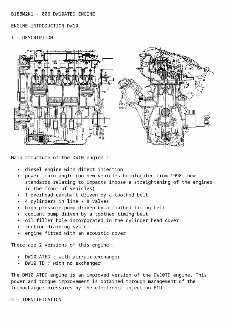
Main structure of the DW10 engine :
diesel engine with direct injection power train angle (on new vehicles homologated from 1998, new standards relating to impacts impose a
straightening of the engines in the front of vehicles) 1 overhead camshaft driven by a toothed belt 4 cylinders in line - 8 valves high pressure pump driven by a toothed timing belt coolant pump driven by a toothed timing belt oil filler hole incorporated in the cylinder head cover suction draining system engine fitted with an acoustic cover
There are 2 versions of this engine :
DW10 ATED : with air/air exchanger DW10 TD : with no exchanger
The DW10 ATED engine is an improved version of the DW10TD engine, This power and torque improvement is obtained through management of the turbocharger pressures by the electronic injection ECU .
2 - IDENTIFICATION
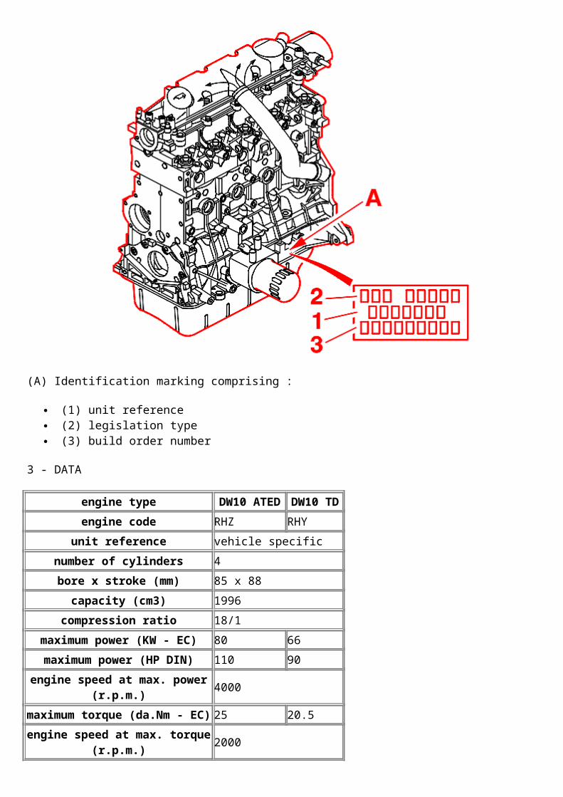
(A) Identification marking comprising :
(1) unit reference (2) legislation type (3) build order number
3 - DATA
engine type DW10 ATED DW10 TD
engine code RHZ RHY
unit reference vehicle specific
number of cylinders 4
bore x stroke (mm) 85 x 88
capacity (cm3) 1996
compression ratio 18/1
maximum power (KW - EC) 80 66
maximum power (HP DIN) 110 90
engine speed at max. power (r.p.m.) 4000
maximum torque (da.Nm - EC) 25 20.5
engine speed at max. torque (r.p.m.) 2000
turbocharger vehicle specific
air/air intercooler yes no
turbocharger pressure (2000 rpm) 1 bar(s)
turbocharger pressure (3000 rpm) 1 bar(s)
injection system COMMON RAIL
make BOSCH
type EDC 15C2
opacity of smoke (m - 1) specific to : vehicles
4 - CYLINDER BLOCK
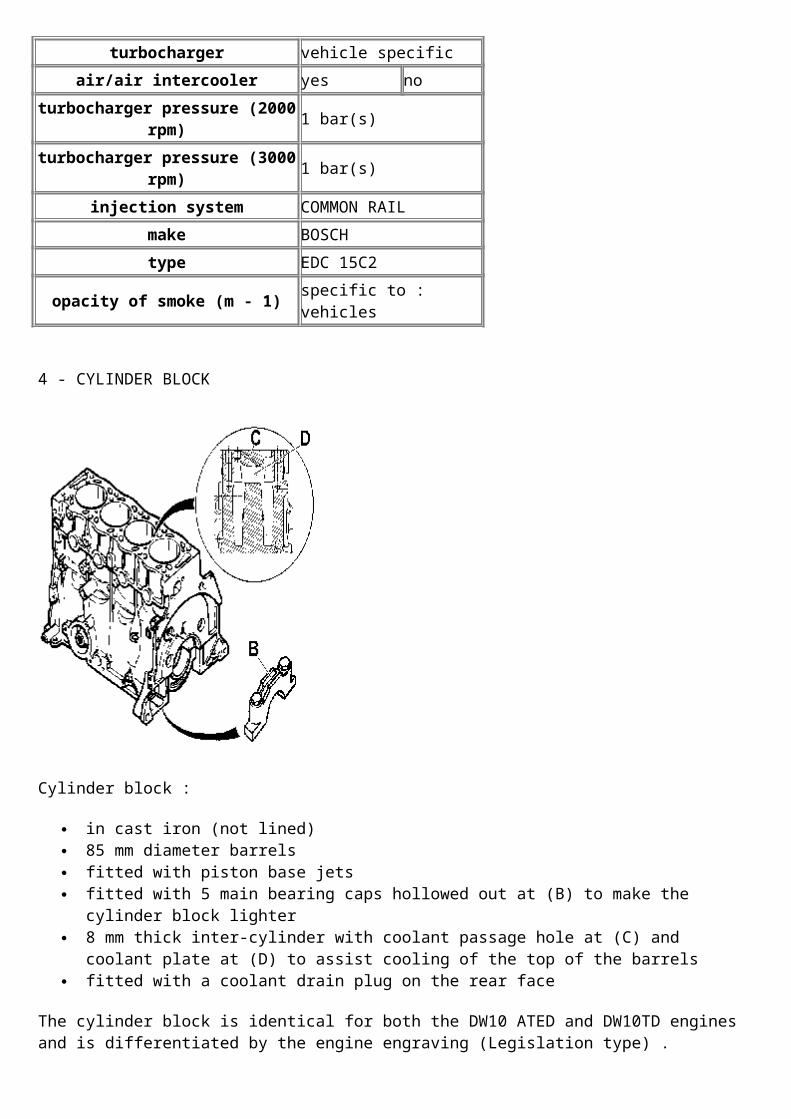
Cylinder block :
in cast iron (not lined) 85 mm diameter barrels fitted with piston base jets fitted with 5 main bearing caps hollowed out at (B) to make the cylinder block lighter 8 mm thick inter-cylinder with coolant passage hole at (C) and coolant plate at (D) to assist cooling of
the top of the barrels fitted with a coolant drain plug on the rear face
The cylinder block is identical for both the DW10 ATED and DW10TD engines and is differentiated by the engine engraving (Legislation type) .
NOTE : no. cylinder-number 1 : clutch end (flywheel) .
5 - CRANKSHAFT AND CONNECTING RODS
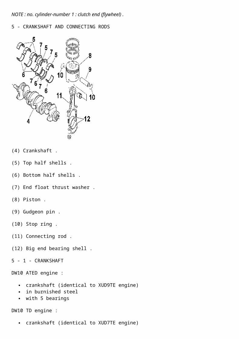
(4) Crankshaft .
(5) Top half shells .
(6) Bottom half shells .
(7) End float thrust washer .
(8) Piston .
(9) Gudgeon pin .
(10) Stop ring .
(11) Connecting rod .
(12) Big end bearing shell .
5 - 1 - CRANKSHAFT
DW10 ATED engine :
crankshaft (identical to XUD9TE engine) in burnished steel with 5 bearings
DW10 TD engine :
crankshaft (identical to XUD7TE engine) material : steel with 5 bearings
Front and rear sealing is by lip seals .
The end float (between 0.07 and 0.32 mm) is adjusted on bearing no. 2 by 4 thrust washers (2 on the cylinder block side and 2 on the crankshaft cap side) .
5 - 2 - CRANKSHAFT HALF SHELLS
Crankshaft half shells :
identical to XUD9TE engine smooth on the main bearing cap side grooved on the cylinder block side
5 - 3 - CONNECTING RODS
New connecting rods (145 mm between centres) (Identical to DW8 engine) :
forged steel connecting rods the little end is fitted with a machined bronze bush in the shape of a snake's head smooth connecting rod half shells with tab
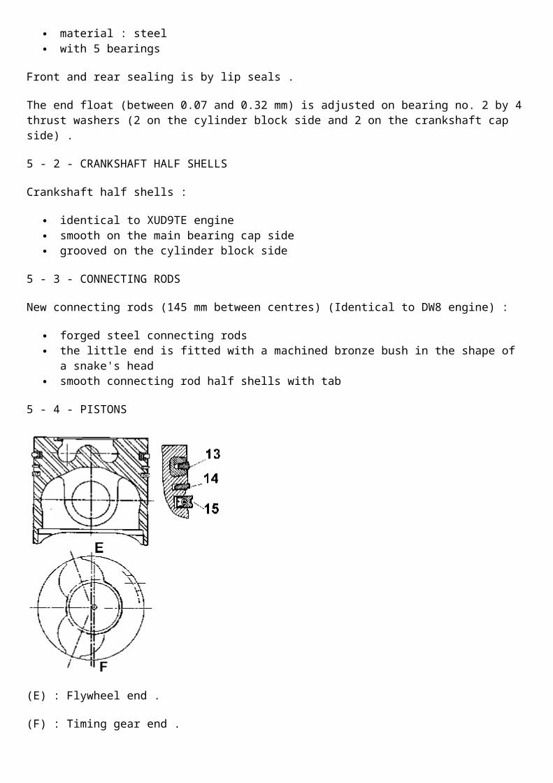
5 - 4 - PISTONS
(E) : Flywheel end .
(F) : Timing gear end .
Special pistons with dome and central cavity (BOWL) necessary for the movement of the gases (SWIRL) .
New light alloy pistons with valve cut-outs .
The direction is given by the valve stamp (stamp on the side opposite the oil filter) .
There is only one piston diameter category (Series) .
There is only one piston diameter category (Repair) .
One weight category, obtained by internal reworking of the pin .
The floating gudgeon pin is retained by 2 rings .
The piston has a steel insert to reinforce the compression ring groove .
5 - 5 - PISTON RINGS
The piston has 3 rings :
upper sealing ring (13): double trapezoid compression ring (thickness = 3.5 mm) lower sealing ring (14): curved (thickness = 2 mm) scraper ring (15): with spiral spring (thickness = 3 mm)
5 - 6 - FLYWHEEL
Flywheel (Adapted for each vehicle) :
in cast iron with lamellar graphite friction plate diameter 275 mm the edge of the flywheel has 60 teeth of which 2 have been omitted to determine Top Dead Centre
5 - 7 - ACCESSORIES PULLEY
A pulley for versions without air conditioning (damped hub with no torsion uncoupling step) .
A pulley for versions with air conditioning (damped hub with torsion uncoupling step) .
These pulleys are secured to the crankshaft by 1 bolt (Identical to XUD) .
6 - CYLINDER HEAD ASSEMBLY
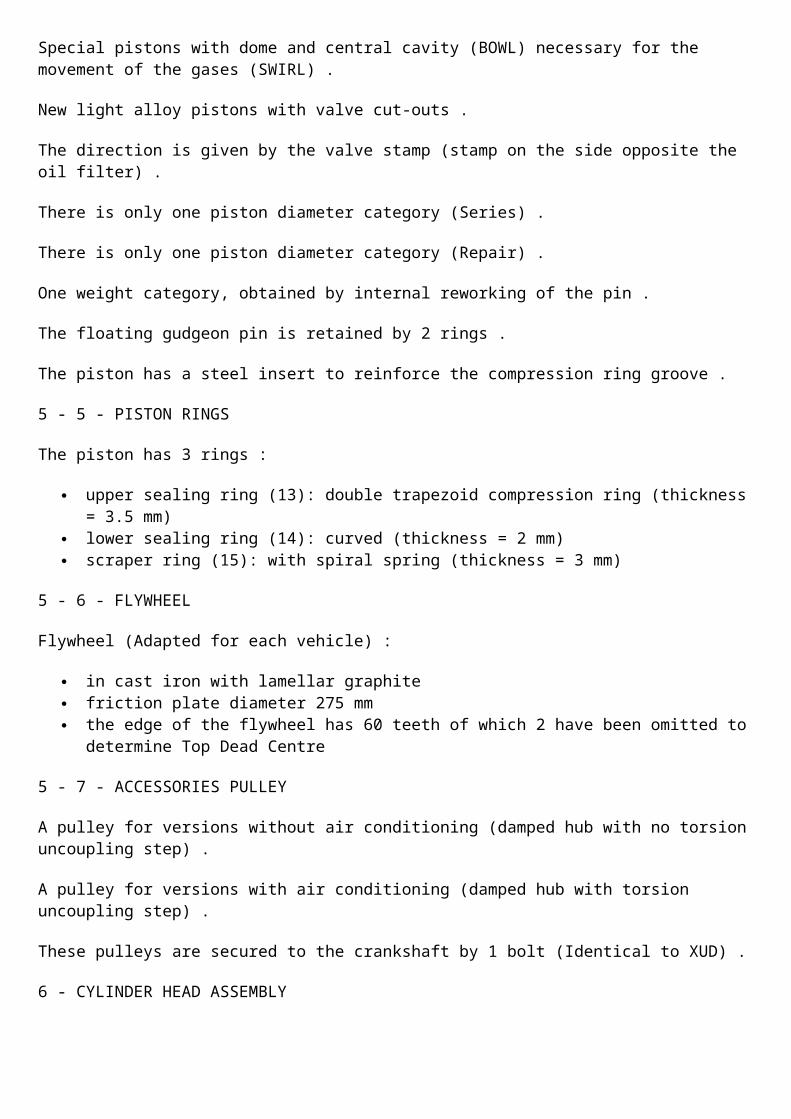
6 - 1 - CYLINDER-HEAD COVER (16)
The cylinder head cover (16) is made from a composite material, it is fitted with a pre-formed removable seal .
The oil filler hole is incorporated in the cylinder head cover .
6 - 2 - CAMSHAFT BEARING CASTING (17)
The camshaft main bearing cap housing (17) is made from a light alloy .
Cap housing/cylinder head sealing is by CAF 33 type sealing compound .
The camshaft is positioned in the cylinder head by the studded cap housing, with 5 main bearings .
The end float adjustment of the camshaft is on bearing no. 3 (Bearing no. 1 on the flywheel end) .
6 - 3 - CYLINDER HEAD (18)
A new cylinder head (18) : 2 valves per cylinder .
Height of new cylinder head : 133 mm .
Maximum cylinder head bow : 0.03 mm .
The inlet ducts in the cylinder head are a complex helical shape to form the SWIRL .
The valve seats and guides are new and made from sintered steel .
NOTE : tightening is in a SPIRAL sequence .
6 - 4 - INJECTORS
The base of each injector resembles the conventional multi-hole model (with specifications adapted to the engine version, for example: 5 holes, 0.16 mm in diameter or 5 X 0.20 or 6 X 0.15) .
There is a control solenoid valve on the top .
NOTE : always replace the copper seal, installed in the cylinder head (after repair) .
6 - 5 - THE CAMSHAFT
The camshaft :
this drives the vacuum pump (flywheel end) it engages the roller cam followers which operate the valves
The hydraulic tappets permit wear take-up maintaining a zero clearance between the camshaft, the cam followers and the valves .
Lubrication is via a longitudinal channel .
Side channels direct the oil to the bearings and cams .
End float value : 0.07 mm to 0.38 mm .
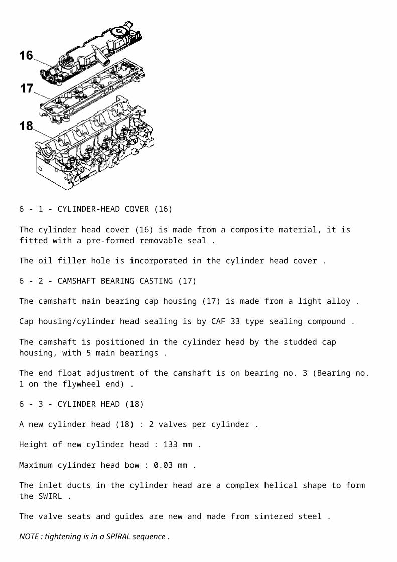
6 - 6 - CYLINDER HEAD GASKET
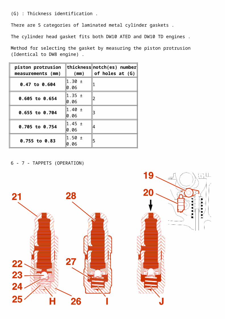
(G) : Thickness identification .
There are 5 categories of laminated metal cylinder gaskets .
The cylinder head gasket fits both DW10 ATED and DW10 TD engines .
Method for selecting the gasket by measuring the piston protrusion (Identical to DW8 engine) .
piston protrusion measurements (mm)
thickness (mm)
notch(es) number of holes at (G)
0.47 to 0.604 1.30 ± 0.06 1
0.605 to 0.654 1.35 ± 0.06 2
0.655 to 0.704 1.40 ± 0.06 3
0.705 to 0.754 1.45 ± 0.06 4
0.755 to 0.83 1.50 ± 0.06 5
6 - 7 - TAPPETS (OPERATION)
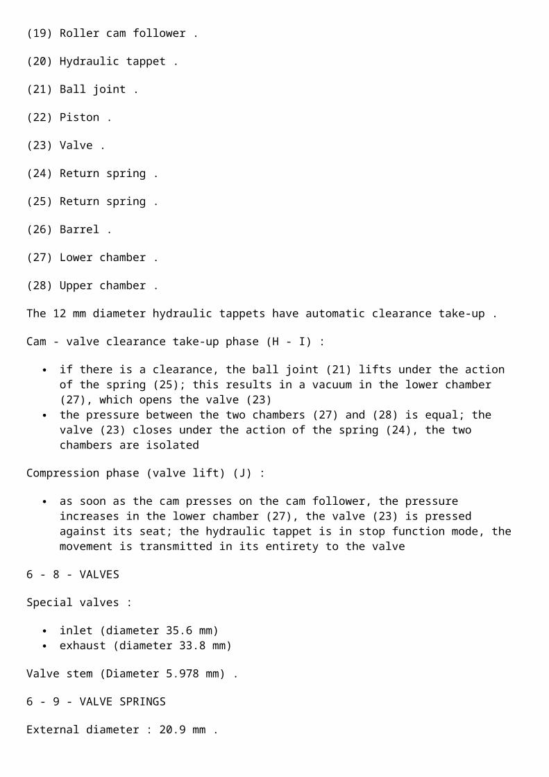
(19) Roller cam follower .
(20) Hydraulic tappet .
(21) Ball joint .
(22) Piston .
(23) Valve .
(24) Return spring .
(25) Return spring .
(26) Barrel .
(27) Lower chamber .
(28) Upper chamber .
The 12 mm diameter hydraulic tappets have automatic clearance take-up .
Cam - valve clearance take-up phase (H - I) :
if there is a clearance, the ball joint (21) lifts under the action of the spring (25); this results in a vacuum in the lower chamber (27), which opens the valve (23)
the pressure between the two chambers (27) and (28) is equal; the valve (23) closes under the action of the spring (24), the two chambers are isolated
Compression phase (valve lift) (J) :
as soon as the cam presses on the cam follower, the pressure increases in the lower chamber (27), the valve (23) is pressed against its seat; the hydraulic tappet is in stop function mode, the movement is transmitted in its entirety to the valve
replacement interval (km)in normal conditions of use
160 000
replacement interval (km)in arduous conditions of use
120 000
NOTE : the belt is tensioned on fitting by the manual tensioner roller (eccentric) requiring the fitting of the SEEM tension checking equipment .
7 - 3 - HIGH PRESSURE PUMP
The high pressure pump has three radial pistons and is driven in a non synchronous manner by the timing .
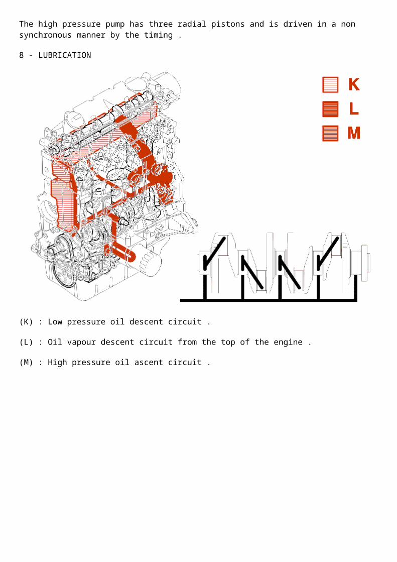
8 - LUBRICATION
(K) : Low pressure oil descent circuit .
(L) : Oil vapour descent circuit from the top of the engine .
(M) : High pressure oil ascent circuit .
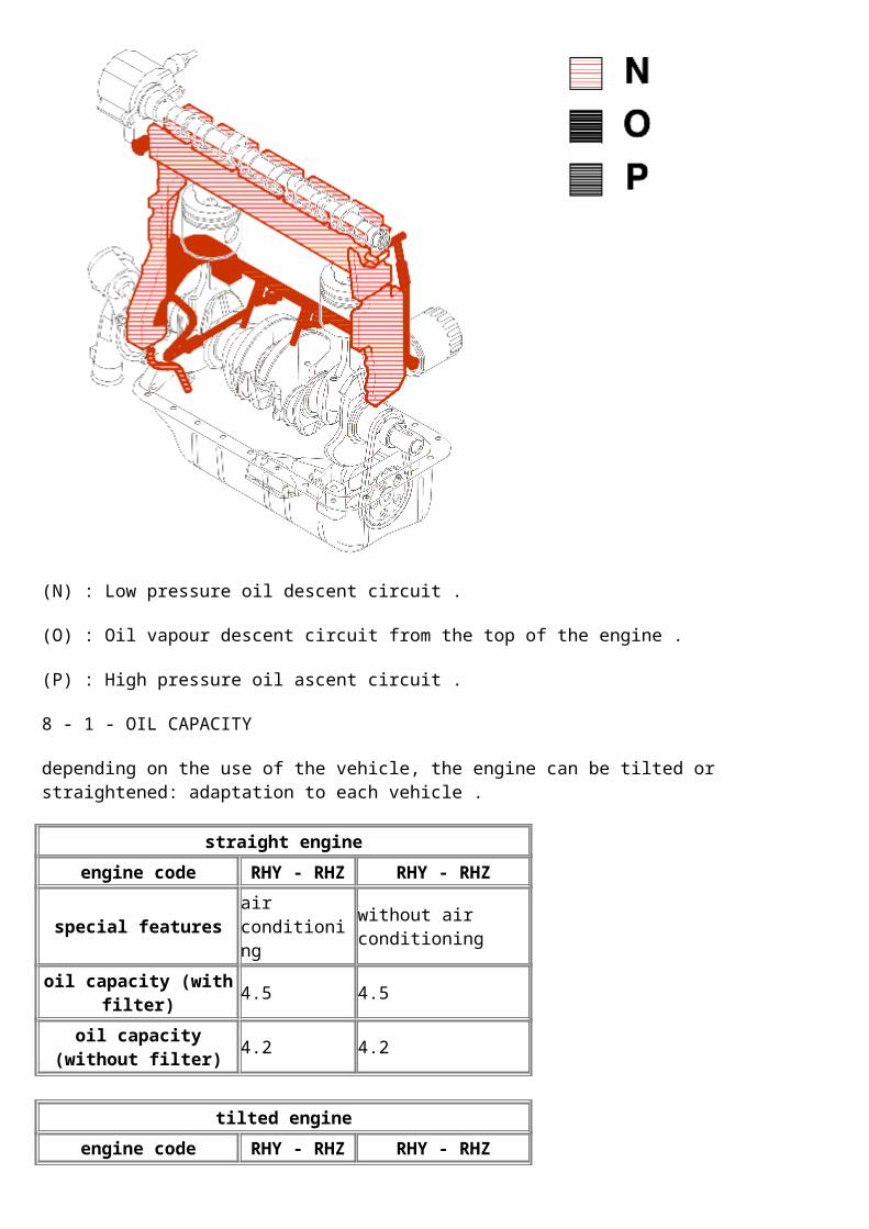
(N) : Low pressure oil descent circuit .
(O) : Oil vapour descent circuit from the top of the engine .
(P) : High pressure oil ascent circuit .
8 - 1 - OIL CAPACITY
depending on the use of the vehicle, the engine can be tilted or straightened: adaptation to each vehicle .
straight engine
engine code RHY - RHZ RHY - RHZ
special features air conditioning without air conditioning
oil capacity (with filter) 4.5 4.5
oil capacity (without filter)
4.2 4.2
tilted engine
engine code RHY - RHZ RHY - RHZ
special features air conditioning without air conditioning
oil capacity (with filter) 4.25 4.25
oil capacity (without filter)
4 4
IMPERATIVE : always check the oil level using the dipstick .
Oil change interval (Engine oil) : Refer to the maintenance documents .
8 - 2 - ENGINE OIL FILTER CARTRIDGE
Oil filter cartridge (First assembly) :
PURFLUX LS 867A (diameter 76 mm)
Oil filter cartridge (Spare) :
PURFLUX LS 867B (diameter 76 mm, valve : 1.5 bar(s))
Replacement interval (Engine oil filter cartridge) : Refer to the maintenance documents .
8 - 3 - LUBRICATION SYSTEM
The piston bases are cooled by jets .
Engine oil pressure at 80°C measured in place of the pressure switch .
engine code RHZ RHY
check 1minimum pressure (bar(s))
1000 rpm2
1000 rpm2
check 2minimum pressure (bar(s))
2000 rpm2.8
2000 rpm2.8
check 3minimum pressure (bar(s))
3000 rpm3.8
3000 rpm3.8
check 4minimum pressure (bar(s))
4000 rpm4
4000 rpm4
8 - 4 - ENGINE OIL CHANGE
The engine oil must be changed with the engine hot just after switching off the engine .
The engine can be drained by suction (End piece ø 14 mm) .
It is still possible to drain the engine by removing the drain plug from the sump .
9 - AIR SUPPLY CIRCUIT
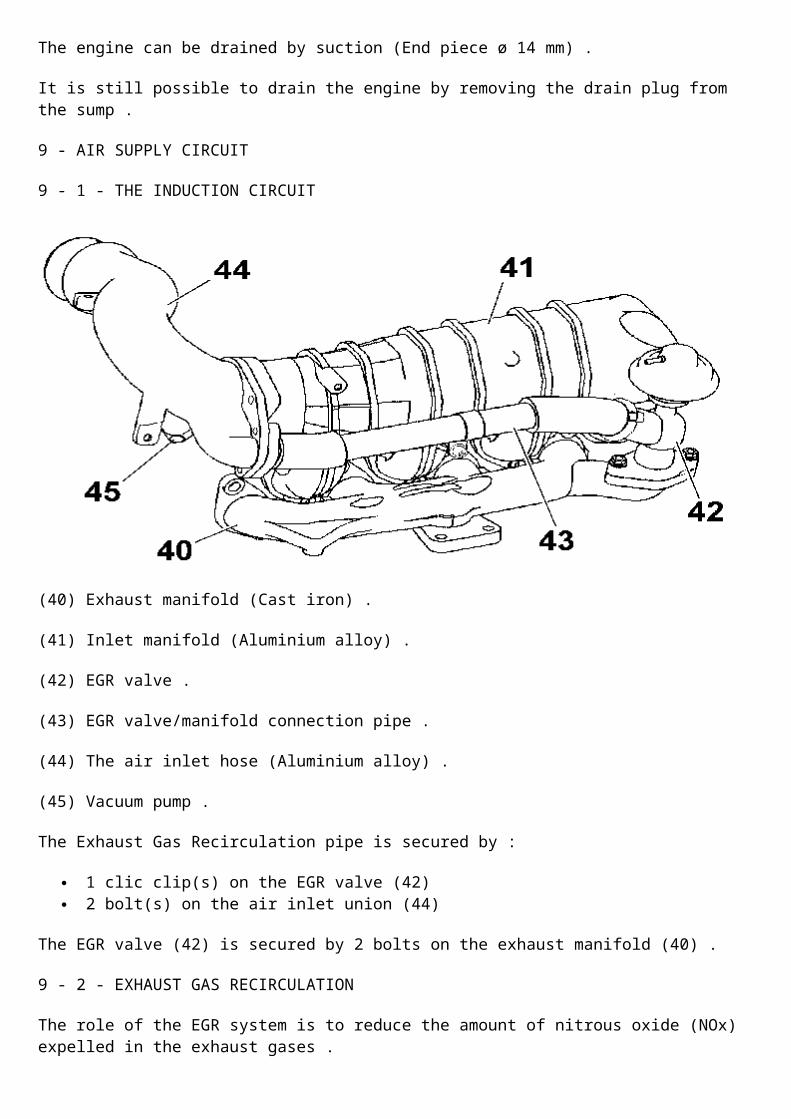
9 - 1 - THE INDUCTION CIRCUIT
(40) Exhaust manifold (Cast iron) .
(41) Inlet manifold (Aluminium alloy) .
(42) EGR valve .
(43) EGR valve/manifold connection pipe .
(44) The air inlet hose (Aluminium alloy) .
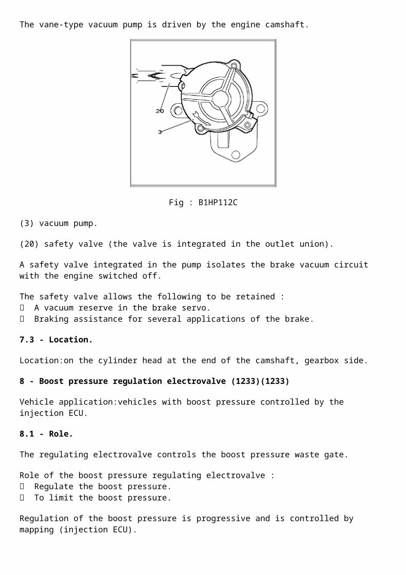
(45) Vacuum pump .
The Exhaust Gas Recirculation pipe is secured by :
1 clic clip(s) on the EGR valve (42) 2 bolt(s) on the air inlet union (44)
The EGR valve (42) is secured by 2 bolts on the exhaust manifold (40) .
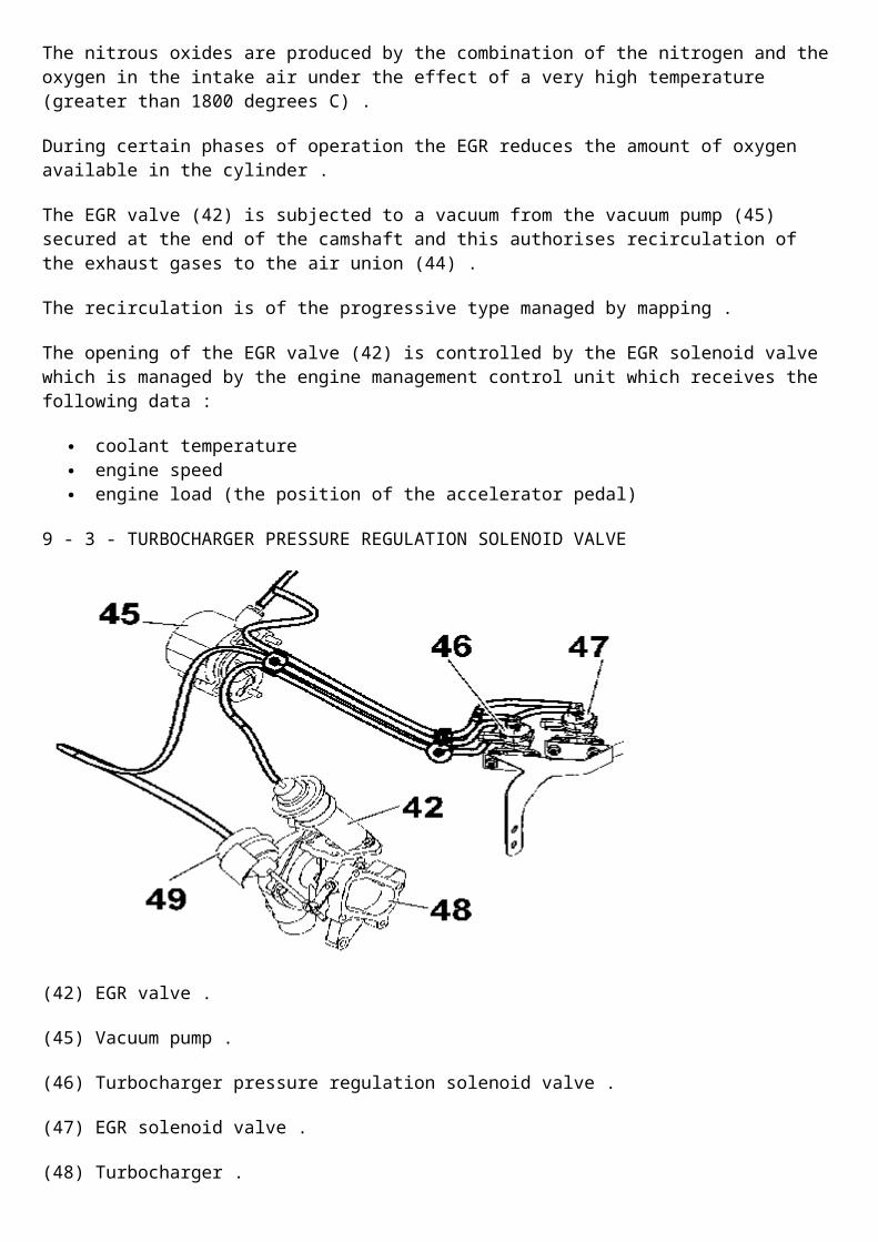
9 - 2 - EXHAUST GAS RECIRCULATION
The role of the EGR system is to reduce the amount of nitrous oxide (NOx) expelled in the exhaust gases .
The nitrous oxides are produced by the combination of the nitrogen and the oxygen in the intake air under the effect of a very high temperature (greater than 1800 degrees C) .
During certain phases of operation the EGR reduces the amount of oxygen available in the cylinder .
The EGR valve (42) is subjected to a vacuum from the vacuum pump (45) secured at the end of the camshaft and this authorises recirculation of the exhaust gases to the air union (44) .
The recirculation is of the progressive type managed by mapping .
The opening of the EGR valve (42) is controlled by the EGR solenoid valve which is managed by the engine management control unit which receives the following data :
coolant temperature engine speed engine load (the position of the accelerator pedal)
Controlled by the ECU, this solenoid valve enables it to regulate the intake pressure via the turbo regulation valve (49) .
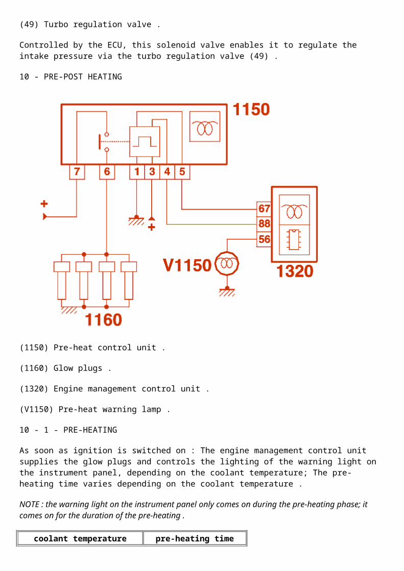
10 - PRE-POST HEATING
(1150) Pre-heat control unit .
(1160) Glow plugs .
(1320) Engine management control unit .
(V1150) Pre-heat warning lamp .
10 - 1 - PRE-HEATING
As soon as ignition is switched on : The engine management control unit supplies the glow plugs and controls the lighting of the warning light on the instrument panel, depending on the coolant temperature; The pre-heating time varies depending on the coolant temperature .
NOTE : the warning light on the instrument panel only comes on during the pre-heating phase; it comes on for the duration of the pre-heating .
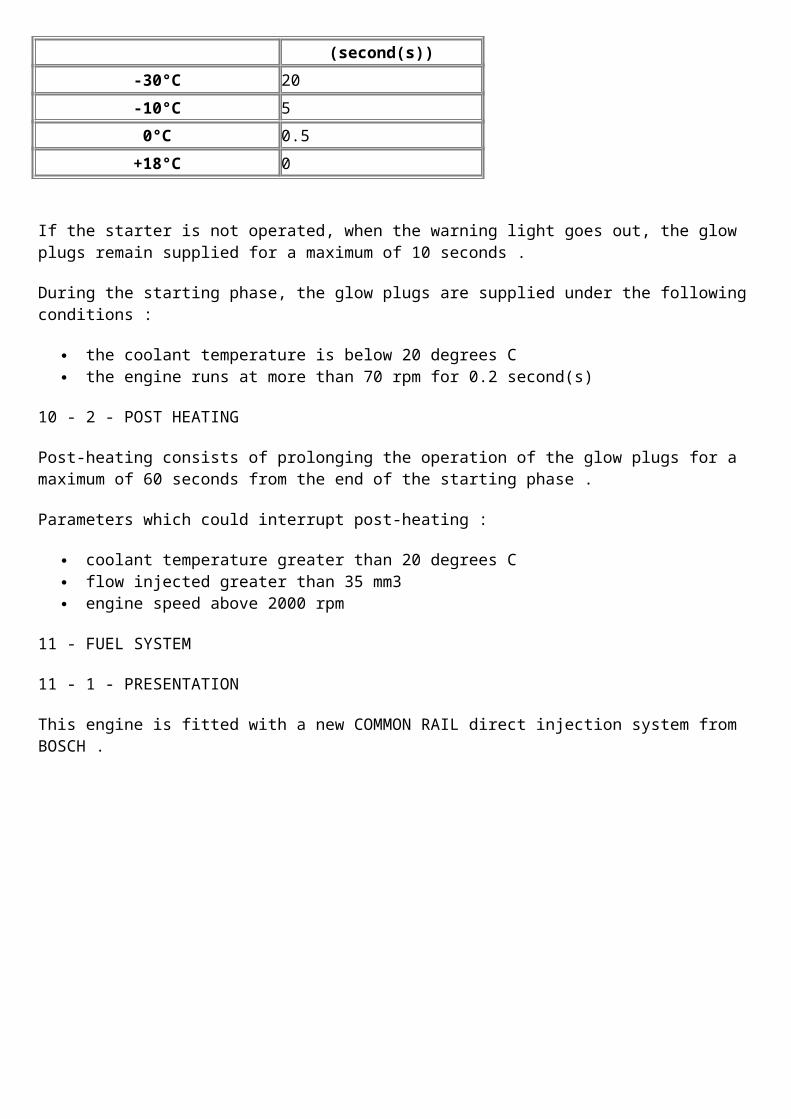
coolant temperaturepre-heating time
(second(s))
-30°C 20
-10°C 5
0°C 0.5
+18°C 0
If the starter is not operated, when the warning light goes out, the glow plugs remain supplied for a maximum of 10 seconds .
During the starting phase, the glow plugs are supplied under the following conditions :
the coolant temperature is below 20 degrees C the engine runs at more than 70 rpm for 0.2 second(s)
10 - 2 - POST HEATING
Post-heating consists of prolonging the operation of the glow plugs for a maximum of 60 seconds from the end of the starting phase .
Parameters which could interrupt post-heating :
coolant temperature greater than 20 degrees C flow injected greater than 35 mm3 engine speed above 2000 rpm
11 - FUEL SYSTEM
11 - 1 - PRESENTATION
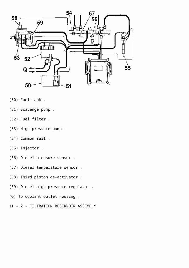
This engine is fitted with a new COMMON RAIL direct injection system from BOSCH .
(50) Fuel tank .
(51) Scavenge pump .
(52) Fuel filter .
(53) High pressure pump .
(54) Common rail .
(55) Injector .
(56) Diesel pressure sensor .
(57) Diesel temperature sensor .
(58) Third piston de-activator .
(59) Diesel high pressure regulator .
(Q) To coolant outlet housing .
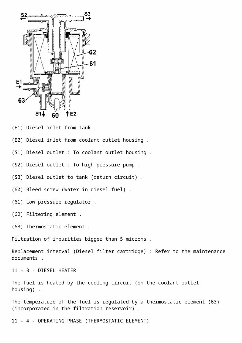
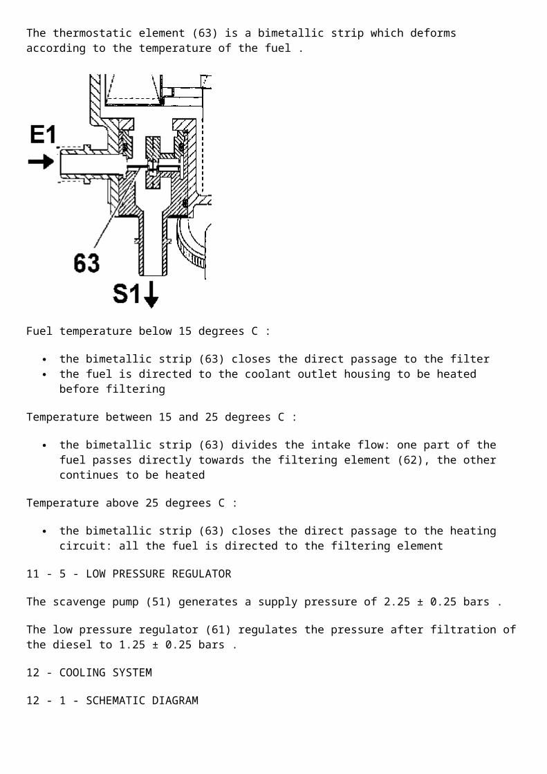
11 - 2 - FILTRATION RESERVOIR ASSEMBLY
(E1) Diesel inlet from tank .
(E2) Diesel inlet from coolant outlet housing .
(S1) Diesel outlet : To coolant outlet housing .
(S2) Diesel outlet : To high pressure pump .
(S3) Diesel outlet to tank (return circuit) .
(60) Bleed screw (Water in diesel fuel) .
(61) Low pressure regulator .
(62) Filtering element .
(63) Thermostatic element .
Filtration of impurities bigger than 5 microns .
Replacement interval (Diesel filter cartridge) : Refer to the maintenance documents .
11 - 3 - DIESEL HEATER
The fuel is heated by the cooling circuit (on the coolant outlet housing) .
The temperature of the fuel is regulated by a thermostatic element (63) (incorporated in the filtration reservoir) .
11 - 4 - OPERATING PHASE (THERMOSTATIC ELEMENT)
The thermostatic element (63) is a bimetallic strip which deforms according to the temperature of the fuel .
Fuel temperature below 15 degrees C :
the bimetallic strip (63) closes the direct passage to the filter the fuel is directed to the coolant outlet housing to be heated before filtering
Temperature between 15 and 25 degrees C :
the bimetallic strip (63) divides the intake flow: one part of the fuel passes directly towards the filtering element (62), the other continues to be heated
Temperature above 25 degrees C :
the bimetallic strip (63) closes the direct passage to the heating circuit: all the fuel is directed to the filtering element
11 - 5 - LOW PRESSURE REGULATOR
The scavenge pump (51) generates a supply pressure of 2.25 ± 0.25 bars .
The low pressure regulator (61) regulates the pressure after filtration of the diesel to 1.25 ± 0.25 bars .
12 - COOLING SYSTEM
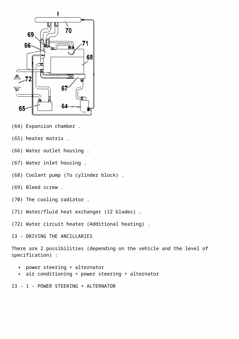
12 - 1 - SCHEMATIC DIAGRAM
(64) Expansion chamber .
(65) heater matrix .
(66) Water outlet housing .
(67) Water inlet housing .
(68) Coolant pump (To cylinder block) .
(69) Bleed screw .
(70) The cooling radiator .
(71) Water/fluid heat exchanger (12 blades) .
(72) Water circuit heater (Additional heating) .
13 - DRIVING THE ANCILLARIES
There are 2 possibilities (depending on the vehicle and the level of specification) :
power steering + alternator air conditioning + power steering + alternator
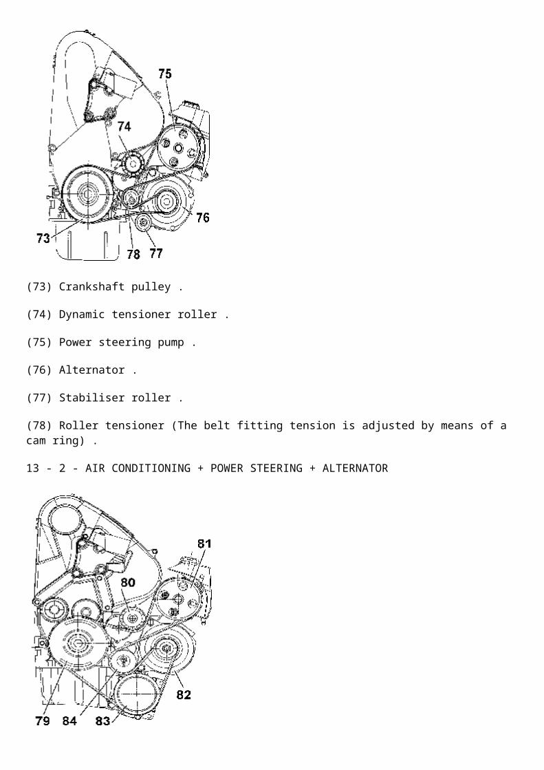
13 - 1 - POWER STEERING + ALTERNATOR
(73) Crankshaft pulley .
(74) Dynamic tensioner roller .
(75) Power steering pump .
(76) Alternator .
(77) Stabiliser roller .
(78) Roller tensioner (The belt fitting tension is adjusted by means of a cam ring) .
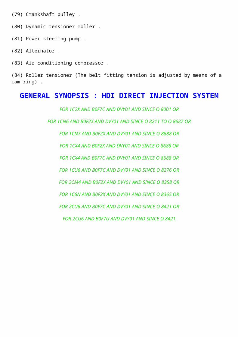
13 - 2 - AIR CONDITIONING + POWER STEERING + ALTERNATOR
(79) Crankshaft pulley .
(80) Dynamic tensioner roller .
(81) Power steering pump .
(82) Alternator .
(83) Air conditioning compressor .
(84) Roller tensioner (The belt fitting tension is adjusted by means of a cam ring) .
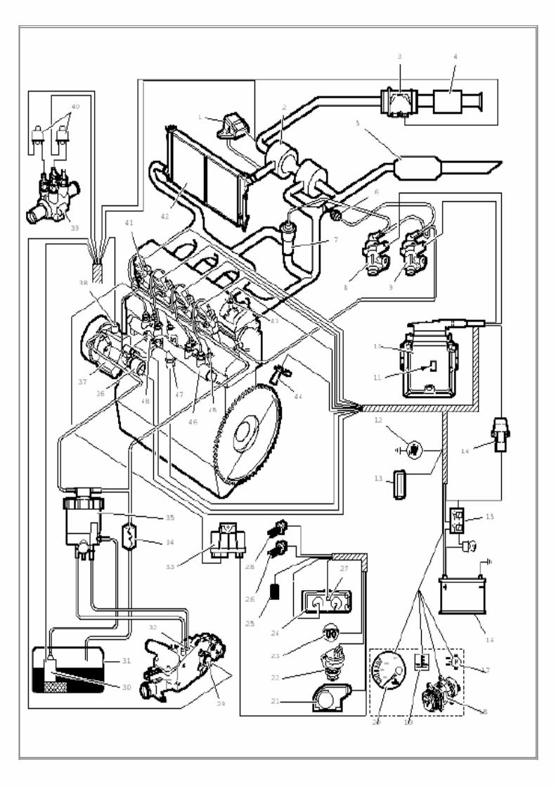
GENERAL SYNOPSIS : HDI DIRECT INJECTION SYSTEM
FOR 1C2X AND B0F7C AND DVY01 AND SINCE O 8001 OR
FOR 1CN6 AND B0F2X AND DVY01 AND SINCE O 8211 TO O 8687 OR
FOR 1CN7 AND B0F2X AND DVY01 AND SINCE O 8688 OR
FOR 1CX4 AND B0F2X AND DVY01 AND SINCE O 8688 OR
FOR 1CX4 AND B0F7C AND DVY01 AND SINCE O 8688 OR
FOR 1CU6 AND B0F7C AND DVY01 AND SINCE O 8276 OR
FOR 2CM4 AND B0F2X AND DVY01 AND SINCE O 8358 OR
FOR 1C6N AND B0F2X AND DVY01 AND SINCE O 8365 OR
FOR 2CU6 AND B0F7C AND DVY01 AND SINCE O 8421 OR
FOR 2CU6 AND B0F7U AND DVY01 AND SINCE O 8421
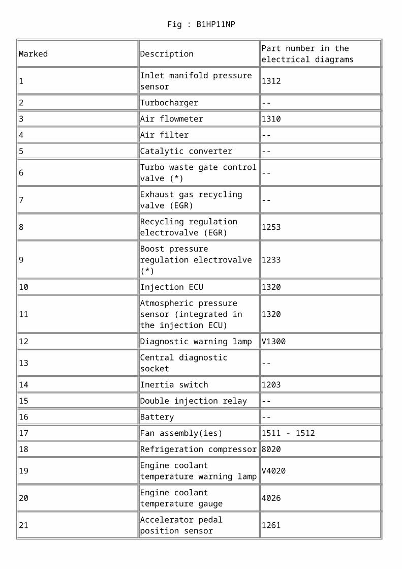
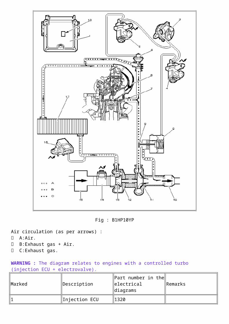
Fig : B1HP11NP
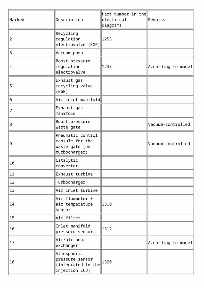
Marked DescriptionPart number in the electrical diagrams
1 Inlet manifold pressure sensor 1312
2 Turbocharger --
3 Air flowmeter 1310
4 Air filter --
5 Catalytic converter --
6 Turbo waste gate control valve (*) --
7 Exhaust gas recycling valve (EGR) --
8Recycling regulation electrovalve (EGR)
1253
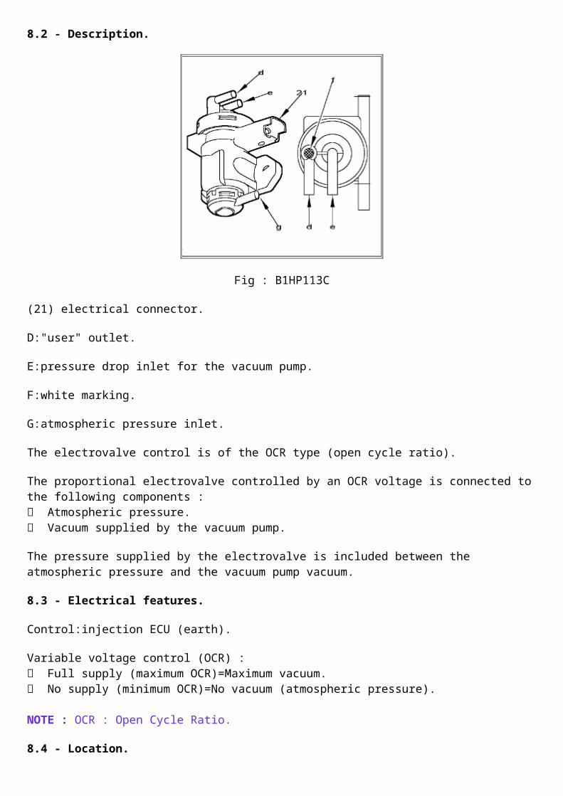
9Boost pressure regulation electrovalve (*)
1233
10 Injection ECU 1320
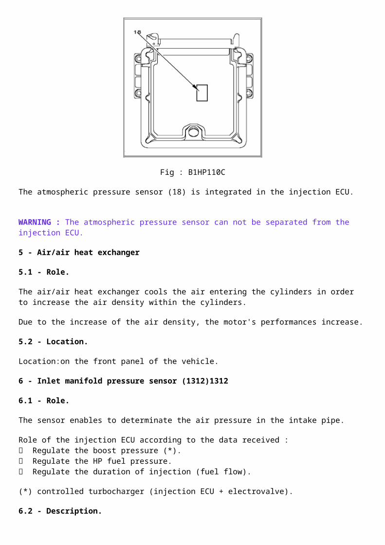
11Atmospheric pressure sensor (integrated in the injection ECU)
1320
12 Diagnostic warning lamp V1300
13 Central diagnostic socket --
14 Inertia switch 1203
15 Double injection relay --
16 Battery --
17 Fan assembly(ies) 1511 - 1512
18 Refrigeration compressor 8020
19Engine coolant temperature warning lamp
V4020
20 Engine coolant temperature gauge 4026
21 Accelerator pedal position sensor 1261
22 Vehicle speed sensor 1620
23 Preheating warning lamp V1150
24 Electronic tachometer 9000
25 Electronic anti-theft device 8221 - 8630
26 Brake pedal switch --
27 Trip computer (*) --
28 Clutch pedal switch 7306
29 Engine coolant temperature sensor 1220
30 Booster pump (low pressure) 1211
31 Fuel tank --
32 Fuel heater --
33 Pre-post heating control unit 1150
34 Fuel cooler --
35 Fuel filter --
36 Fuel high pressure regulator 1322
37 High pressure fuel pump --
38Deactivator of the 3rd piston of the high pressure fuel pump
1208-6
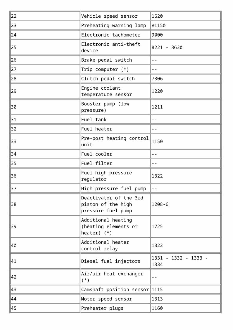
39Additional heating (heating elements or heater) (*)
FOR 1CN6 AND B0F2X AND DVY01 AND SINCE O 8211 TO O 8687 OR
FOR 1CN7 AND B0F2X AND DVY01 AND SINCE O 8688 OR
FOR 1CX4 AND B0F2X AND DVY01 AND SINCE O 8688 OR
FOR 1CX4 AND B0F2X AND DVY01 AND SINCE O 8688 OR
FOR 1C6N AND B0F2X AND DVY01 AND SINCE O 8365 OR
FOR 1CU6 AND B0F7C AND DVY01 AND SINCE O 8276 OR
FOR 2CM4 AND B0F2X AND DVY01 AND SINCE O 8358 OR
FOR 2CU6 AND B0F7C AND DVY01 AND SINCE O 8421 OR
FOR 2CU6 AND B0F7U AND DVY01 AND SINCE O 8421
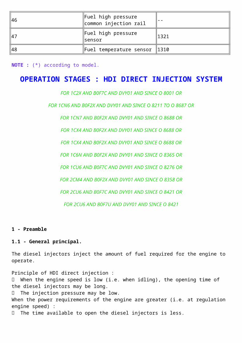
1 - Preamble
1.1 - General principal.
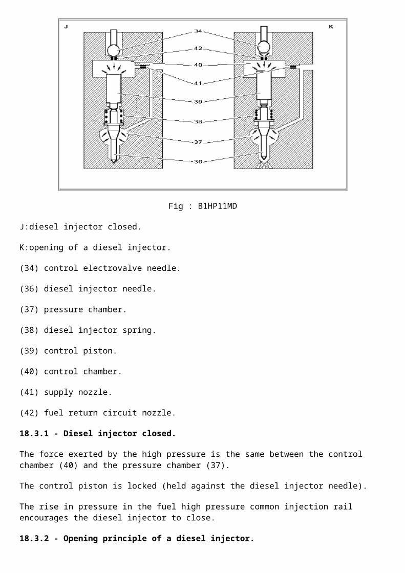
The diesel injectors inject the amount of fuel required for the engine to operate.
Principle of HDI direct injection : When the engine speed is low (i.e. when idling), the opening time of the diesel injectors may be long. The injection pressure may be low.When the power requirements of the engine are greater (i.e. at regulation engine speed) : The time available to open the diesel injectors is less. The fuel injection pressure must be much higher.The design of the HDI direct injection system means that the following 3 parameters can be modified : Injection pressure (by taking fuel at high pressure from the injection rail). Flow of injected fuel (by adjusting the diesel injector opening time). Injection start.
NOTE : HDI injection is defined as the combination of the above 3 parameters.
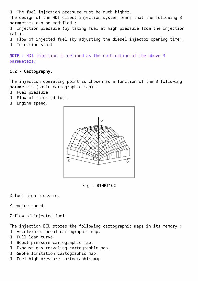
1.2 - Cartography.
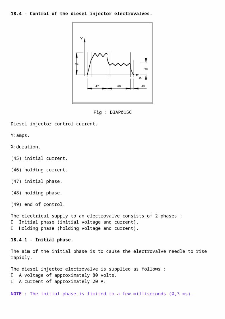
The injection operating point is chosen as a function of the 3 following parameters (basic cartographic map) : Fuel pressure. Flow of injected fuel. Engine speed.
Fig : B1HP11QC
X:fuel high pressure.
Y:engine speed.
Z:flow of injected fuel.
The injection ECU stores the following cartographic maps in its memory : Accelerator pedal cartographic map. Full load curve. Boost pressure cartographic map. Exhaust gas recycling cartographic map. Smoke limitation cartographic map. Fuel high pressure cartographic map.
2 - Injection synopsis
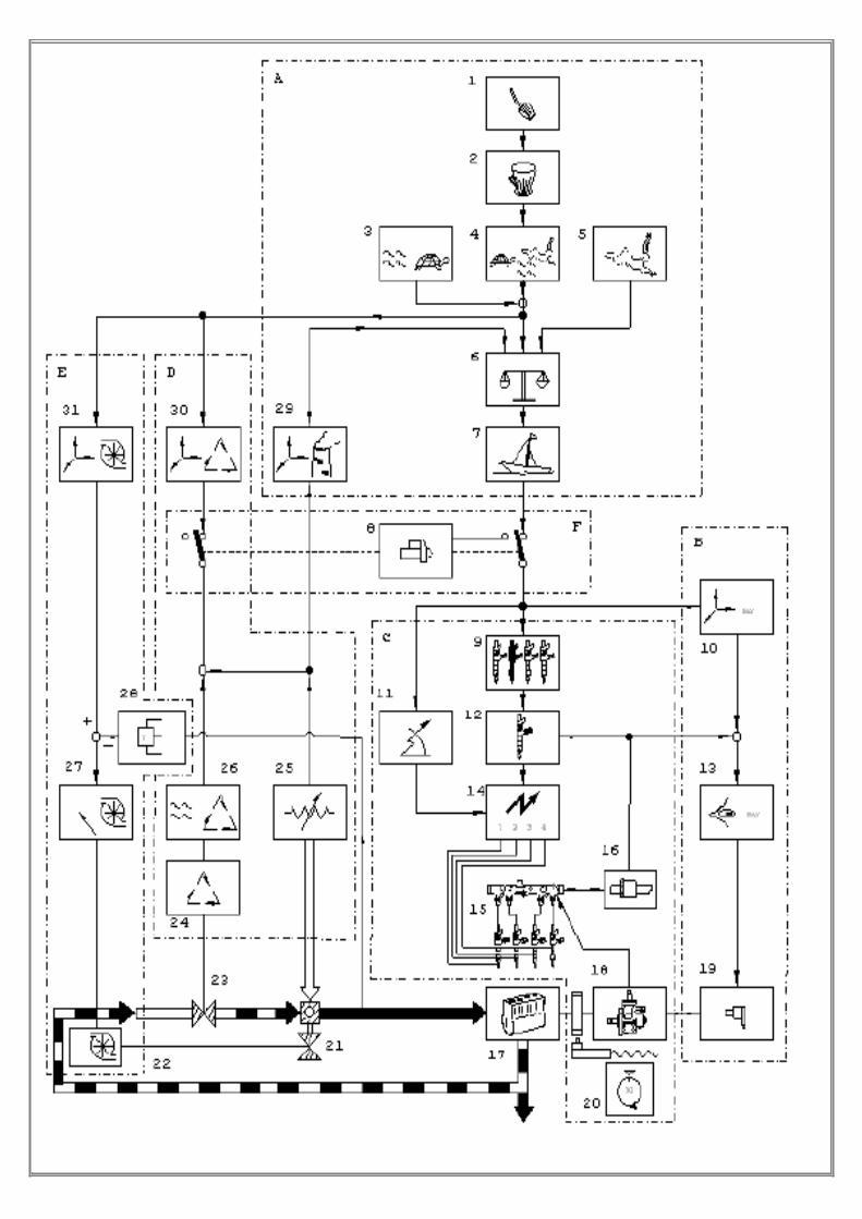
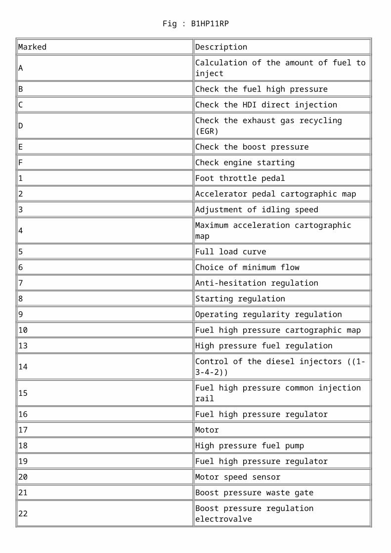
Fig : B1HP11RP
Marked Description
A Calculation of the amount of fuel to inject
B Check the fuel high pressure
C Check the HDI direct injection
D Check the exhaust gas recycling (EGR)
E Check the boost pressure
F Check engine starting
1 Foot throttle pedal
2 Accelerator pedal cartographic map
3 Adjustment of idling speed
4 Maximum acceleration cartographic map
5 Full load curve
6 Choice of minimum flow
7 Anti-hesitation regulation
8 Starting regulation
9 Operating regularity regulation
10 Fuel high pressure cartographic map
13 High pressure fuel regulation
14 Control of the diesel injectors ((1-3-4-2))
15 Fuel high pressure common injection rail
16 Fuel high pressure regulator
17 Motor
18 High pressure fuel pump
19 Fuel high pressure regulator
20 Motor speed sensor
21 Boost pressure waste gate
22 Boost pressure regulation electrovalve
23 Exhaust gas recycling valve (EGR)
24 Recycling regulation electrovalve (EGR)
25 Air flowmeter
26 Regulation of the exhaust gas recycling (EGR)
27 Boost pressure regulation
28 Inlet manifold pressure sensor
29 Smoke limitation cartographic map
30 Exhaust gas recycling cartographic map
31 Boost pressure cartographic map
3 - Role of the main cartographic maps
3.1 - Accelerator pedal cartographic map.
Role of the accelerator pedal cartographic map (by filtering the driver's order) : To avoid large variations in fuel flow (driving condition). To obtain good progressiveness (driving condition).
NOTE : The cartographic map is used for calculating the amount of fuel to be injected.
3.2 - Full load curve.
The fuel load curve limits the amount of fuel to be injected.
The full load curve means that the amount of fuel allowable by the engine is not exceeded (mechanical limits, amount of air absorbed by the engine).
3.3 - Boost pressure cartographic map.
Vehicle application:vehicles fitted with a controlled turbocharger.
This cartographic map is used to work out the air turbocharging from the amount of fuel to inject.
3.4 - Exhaust gas recycling cartographic map.
This cartographic map is used to work out the exact exhaust gas recycling rate.
The exhaust gas recycling rate is essentially obtained from the following parameters : Amount of fuel to inject. Atmospheric pressure. Amount of air entering the engine (calculation).
3.5 - Smoke limitation cartographic map.
This cartographic map is used to limit smoke emissions and is used during transitory speeds (i.e. when changing gear).
Example : The driver requests a change of engine speed. There is no longer a balance between the amount of fuel and amount of air.
The cartographic map controls the change in fuel flow with respect to engine speed so as to remain within good smoke emission limits.
3.6 - Fuel high pressure cartographic map.
This cartographic map is used to work out the value of the fuel high pressure as a function of the amount of fuel to inject.
This cartographic map takes into account the engine speed and the calculated amount of fuel to inject.
4 - General operation
The amount of fuel to inject is calculated from the following parameters : Position of the accelerator pedal. Engine operating point (engine speed, temperatures, pressures).As a function of the amount of fuel to inject, the injection ECU works out the following parameters : Fuel high pressure required in the injection rail. Injection start. Injection time.
The injection ECU uses specific strategies when starting and stopping the engine.
5 - Working out the amount of fuel to inject
5.1 - General.
The amount of fuel to inject is worked out using the driver's order as given by the position of the accelerator pedal.
To work out the amount of fuel to inject, the injection ECU takes account of the following : Request of driver (after filtering). Smoke limitation cartographic map. Full load curve (maximum richness cartographic map). Idle cartographic map.
Each cartographic map works out an amount of fuel to inject.
The amount of fuel to inject is chosen in accordance with a preset priority level.
NOTE : If the engine is idling, the value provided by the idle cartographic map is taken into account. The amount of fuel to inject never exceeds the value given by the following cartographic maps : Full load curve. Smoke limitation cartographic map.The amount of fuel worked out is the total amount of fuel injected during the following phases : Pre-injection. Main injection.
NOTE : During the cranking phase, the position of the accelerator pedal is ignored.
5.2 - Specific corrections.
5.2.1 - Idle speed regulation.
Role of the idle regulation function : To regulate the idle speed. To obtain an accelerated idle speed which decreases as the engine heats up. To improve idle speed when the vehicle is moving.
5.2.2 - Injection cut-off.
Injection is cut off in the no load position if the calculated amount of fuel to inject is equal to 0 (vehicle decelerating).
Power take up speed 2200 rpm.
Injection is cut off at overspeed when the engine speed reaches 5300 rpm.
NOTE : When the injection pressure is too high, the injection ECU controls the high pressure fuel regulator with a minimum OCR.
OCR : Open Cycle Ratio.
5.2.3 - Anti-hesitation regulation.
The aim of this function is to refine the initial filtering using the accelerator pedal cartographic map.
When accelerating or decelerating, fuel flow variations are progressively modified.
6 - High pressure fuel regulation
6.1 - General.
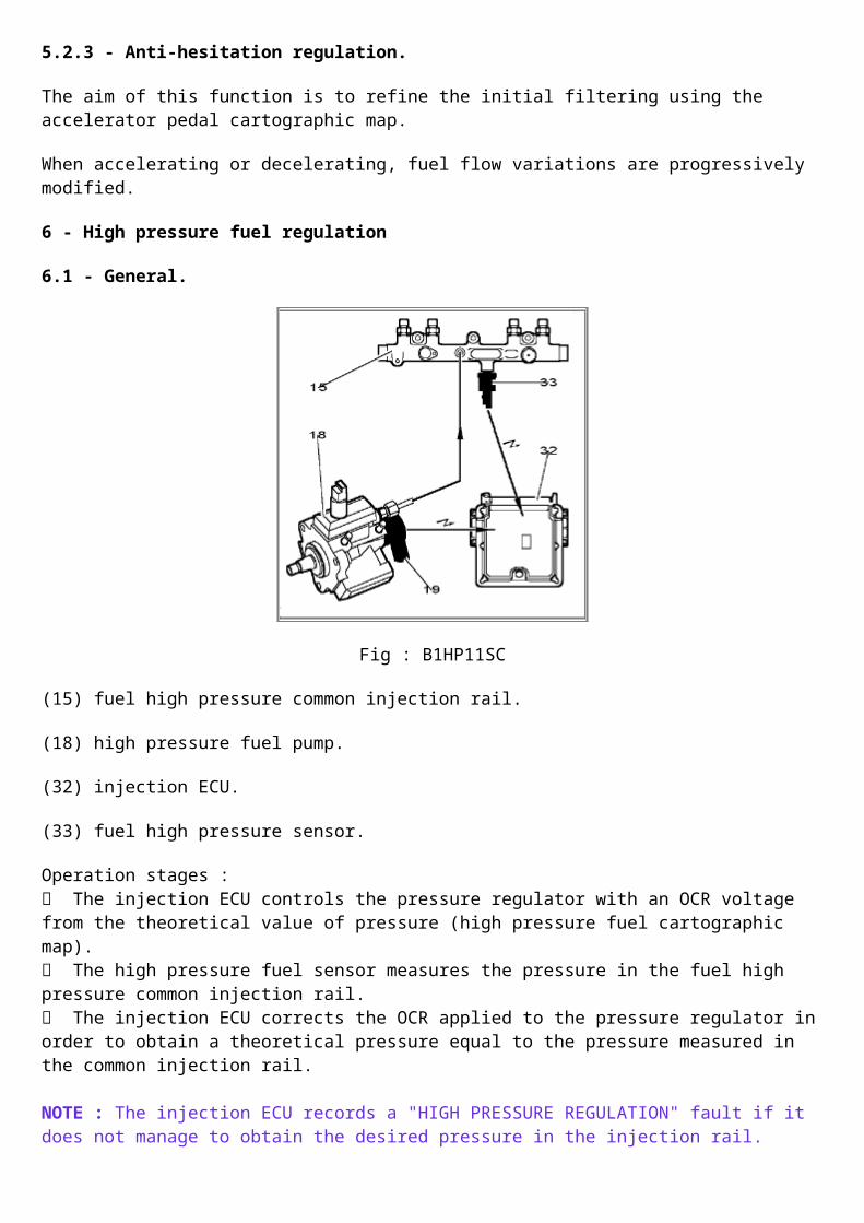
Fig : B1HP11SC
(15) fuel high pressure common injection rail.
(18) high pressure fuel pump.
(32) injection ECU.
(33) fuel high pressure sensor.
Operation stages : The injection ECU controls the pressure regulator with an OCR voltage from the theoretical value of pressure (high pressure fuel cartographic map). The high pressure fuel sensor measures the pressure in the fuel high pressure common injection rail. The injection ECU corrects the OCR applied to the pressure regulator in order to obtain a theoretical pressure equal to the pressure measured in the common injection rail.
NOTE : The injection ECU records a "HIGH PRESSURE REGULATION" fault if it does not manage to obtain the desired pressure in the injection rail.
6.2 - Operation of the 3rd piston deactivator of the high pressure fuel pump.
Fig : B1HP11TD
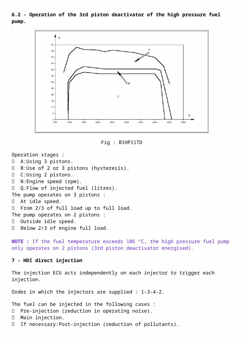
Operation stages : A:Using 3 pistons. B:Use of 2 or 3 pistons (hysteresis). C:Using 2 pistons. N:Engine speed (rpm). Q:Flow of injected fuel (litres).The pump operates on 3 pistons : At idle speed. From 2/3 of full load up to full load.The pump operates on 2 pistons : Outside idle speed. Below 2/3 of engine full load.
NOTE : If the fuel temperature exceeds 106 °C, the high pressure fuel pump only operates on 2 pistons (3rd piston deactivator energised).
7 - HDI direct injection
The injection ECU acts independently on each injector to trigger each injection.
Order in which the injectors are supplied : 1-3-4-2.
The fuel can be injected in the following cases : Pre-injection (reduction in operating noise). Main injection. If necessary:Post-injection (reduction of pollutants).
7.1 - Working out the injection time.
The injection time is worked out from the following parameters : Amount of fuel to inject. Pressure available in the fuel high pressure common injection rail. Engine speed.For one engine cycle, the injection time can be divided into 2 phases : Pre-injection.
Main injection.
7.2 - Working out the start of injection (advance).
The start of the preinjection command is calculated as a function of the amount of fuel to inject.
The injection advance is corrected when the coolant temperature is low.
8 - Working out the injection type
8.1 - Pre-injection.
The start of preinjection is triggered before the main injection.
The injection ECU decides on a preinjection if the engine speed is less than 3200 rpm (reduction in operating noise).
Preinjection is discontinued in the following cases : Engine speed greater than 3200 rpm. High pressure insufficient. Degassing the high pressure common injection rail (starting phase). When the fuel flow is less than a minimum level.
NOTE : The pre-injection time is limited as a function of the high pressure available in the high pressure common injection rail.
8.2 - Main injection.
The start and duration of injection vary essentially depending on whether there is preinjection or not.
Main injection is discontinued in the following cases : Insufficient pressure in the fuel high pressure common injection rail (pressure less than 120 bar). Maximum engine speed reached.
8.3 - Post-injection.
Post-injection combined with a nitrogen oxide catalytic converter can reduce the quantity of nitrogen oxide as well as other pollutants.
Postinjection is characterised by the following parameters : The start of injection, depending on engine speed. The injection time, depending on engine speed, atmospheric pressure, air temperature and coolant temperature.Postinjection is discontinued in the following cases : Catalytic converter temperature outside precise limits. High pressure insufficient. Faulty air flowmeter. Faulty EGR electrovalve. Faulty boost pressure regulation electrovalve. Faulty inlet manifold pressure sensor.
8.4 - Engine operating regularity.
Vibrations are caused when the engine is idling.
The injection ECU works out how smoothly the engine is operating from the following parameters :
Engine speed. Crankshaft position.Role of the injection ECU according to the data received : To analyse the differences in instantaneous rotating speed for each cylinder. To calculate a personalised correction of the fuel flow for each diesel injector, from the rotational speeds measured.
NOTE : Flow correction is expressed as an amount of fuel:X mg of fuel / injection (- 5 to + 5 mg/injection).
9 - Boost pressure regulation
The boost pressure is calculated from the following parameters : Engine speed. Amount of fuel to inject.
The limits of the turbocharging valve vary and depend on the load conditions.
The maximum turbocharging value is 950 mbar between 2500 and 3500 rpm.
The boost pressure can be regulated or controlled in an open loop.
NOTE : When starting the engine, the boost pressure is not regulated. Advantages of a regulated boost pressure : Improvement of driving performance. Better performance/consumption compromise.
10 - Exhaust gas recycling regulation
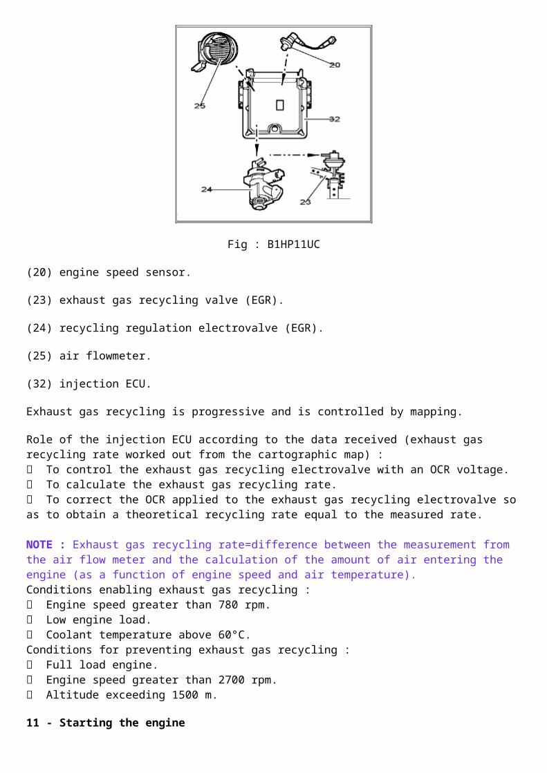
Fig : B1HP11UC
(20) engine speed sensor.
(23) exhaust gas recycling valve (EGR).
(24) recycling regulation electrovalve (EGR).
(25) air flowmeter.
(32) injection ECU.
Exhaust gas recycling is progressive and is controlled by mapping.
Role of the injection ECU according to the data received (exhaust gas recycling rate worked out from the cartographic map) : To control the exhaust gas recycling electrovalve with an OCR voltage. To calculate the exhaust gas recycling rate. To correct the OCR applied to the exhaust gas recycling electrovalve so as to obtain a theoretical recycling rate equal to the measured rate.
NOTE : Exhaust gas recycling rate=difference between the measurement from the air flow meter and the calculation of the amount of air entering the engine (as a function of engine speed and air temperature). Conditions enabling exhaust gas recycling : Engine speed greater than 780 rpm. Low engine load. Coolant temperature above 60°C.Conditions for preventing exhaust gas recycling : Full load engine. Engine speed greater than 2700 rpm. Altitude exceeding 1500 m.
11 - Starting the engine
11.1 - General.
The starting phase is entered as soon as the injection ECU is energised.
When starting, the injection ECU controls the following elements : Booster pump (low pressure) (cuts out after 3 seconds, if the starter motor does not crank). Preheater plugs (if necessary). Fuel high pressure regulator (rise in pressure).
As soon as the starter motor is operated, the injection ECU sets the value of fuel high pressure from the coolant temperature.
At the beginning of starting, the high pressure regulator is controlled by the OCR worked out by the starting cartographic map.
In this operating phase, the high pressure fuel sensor is ignored.
The fuel high pressure is regulated by one of the parameters below : Engine speed greater than 20 rpm with at least 4 revolutions completed. Pressure in the high pressure fuel common injection rail greater than 150 bar.
The starting phase is finished when the engine speed exceeds a value.
NOTE : The injection ECU only operates the injectors when the pressure exceeds 120 bar.
At low engine load, the reference pressure is set at 400 bar.
In the event of starting problems, the injection ECU forces a rise in pressure by sending a maximum OCR command of 40% to 80% (high pressure fuel regulator).
In the event of a faulty high pressure fuel sensor : The injection ECU supplies the high pressure fuel regulator so as to obtain a pressure of 400 bar (high pressure regulator control OCR at 21%).
The pressure in the fuel high pressure common injection rail is no longer regulated.
11.2 - Degassing the fuel high pressure common injection rail.
On a new engine, or after opening the high pressure fuel circuit, the common injection rail should be degassed.
After operating the starter motor for 10 seconds, the injection ECU controls the diesel injectors so as to bleed any air from the circuit.
WARNING : If the minimum pressure of 120 bar is not reached, injection is forbidden and the engine will not start.
12 - Stopping the engine
When switching off the ignition, the injection ECU stops the engine by controlling the following elements : Regulator control voltage=0=Minimum OCR. Supply to the booster pump cut. Stops by cutting the control of the diesel injectors. Control stages of the diesel injectors cut (in the injection ECU).
NOTE : The cut-off orders are performed in a different order every time the engine is stopped to allow the injection ECU to perform a diagnostic.
After stopping the engine, the double relay remains energised for 4 seconds to allow the injection ECU to perform a diagnostic on the components of the injection system.
13 - Engine operation protection
13.1 - Overspeed protection.
The injection ECU permanently monitors the engine speed.
As soon as the engine speed exceeds the maximum value (5300 rpm), injection is cut.
NOTE : During an injection cut-off phase, the injection ECU regulates the fuel high pressure.
13.2 - Anti-boil function.
In addition to an optimised cooling circuit, the injection ECU incorporates a coolant anti-boil strategy.
When driving in severe conditions, the amount of fuel injected is limited to prevent the coolant from boiling (towing at GTW, maximum speed).
The effect on the vehicle results in a reduction in speed when towing and at maximum speed.
NOTE : Gross train weight (GTW).
14 - Pre-post heating
The pre-heating and post-heating times are determined by the ECU in accordance with the engine's cooling liquid's temperature.
14.1 - Preheating operation.
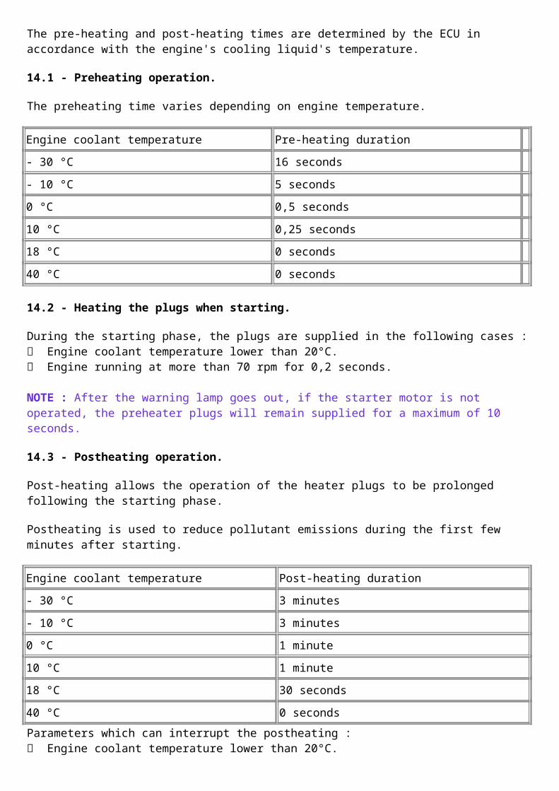
The preheating time varies depending on engine temperature.
Engine coolant temperature Pre-heating duration
- 30 °C 16 seconds
- 10 °C 5 seconds
0 °C 0,5 seconds
10 °C 0,25 seconds
18 °C 0 seconds
40 °C 0 seconds
14.2 - Heating the plugs when starting.
During the starting phase, the plugs are supplied in the following cases : Engine coolant temperature lower than 20°C. Engine running at more than 70 rpm for 0,2 seconds.
NOTE : After the warning lamp goes out, if the starter motor is not operated, the preheater plugs will remain supplied for a maximum of 10 seconds.
14.3 - Postheating operation.
Post-heating allows the operation of the heater plugs to be prolonged following the starting phase.
Postheating is used to reduce pollutant emissions during the first few minutes after starting.
Engine coolant temperature Post-heating duration
- 30 °C 3 minutes
- 10 °C 3 minutes
0 °C 1 minute
10 °C 1 minute
18 °C 30 seconds
40 °C 0 seconds
Parameters which can interrupt the postheating : Engine coolant temperature lower than 20°C. Injected fuel flow exceeding 35 mm3. Engine speed greater than 2000 rpm.
15 - Additional heating
Application:depending on vehicle and marketing country.
Given the high efficiency of the engine, the temperature in the passenger compartment must be helped to rise during cold weather.
The passenger compartment temperature rise assistance is controlled by the injection ECU.
2 devices are used depending on the country in which the vehicle is marketed :
An additional heater supplied with fuel is located in the front left hand wheel arch (vehicles for extremely cold countries). Several additional heating elements (electrical resistors) located in the coolant system of the heater matrix.
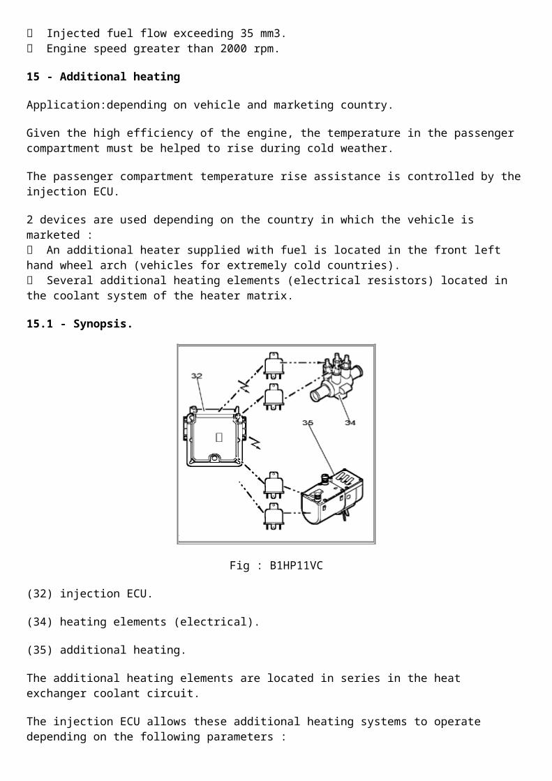
15.1 - Synopsis.
Fig : B1HP11VC
(32) injection ECU.
(34) heating elements (electrical).
(35) additional heating.
The additional heating elements are located in series in the heat exchanger coolant circuit.
The injection ECU allows these additional heating systems to operate depending on the following parameters : Engine coolant temperature. External air temperature.
15.2 - Presentation of the additional heating systems.
15.2.1 - Heating elements (electrical).
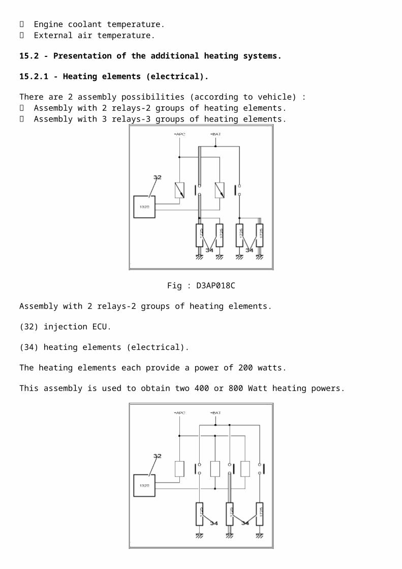
There are 2 assembly possibilities (according to vehicle) : Assembly with 2 relays-2 groups of heating elements. Assembly with 3 relays-3 groups of heating elements.
Fig : D3AP018C
Assembly with 2 relays-2 groups of heating elements.
(32) injection ECU.
(34) heating elements (electrical).
The heating elements each provide a power of 200 watts.
This assembly is used to obtain two 400 or 800 Watt heating powers.
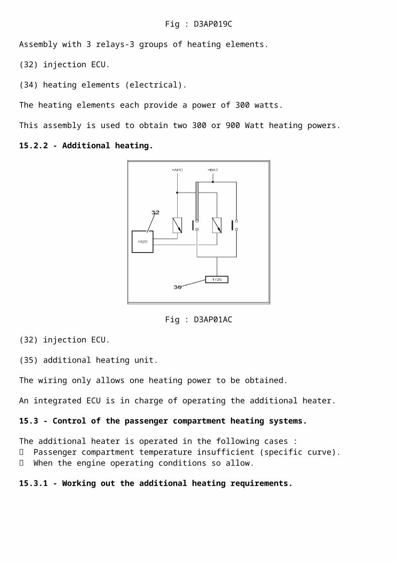
Fig : D3AP019C
Assembly with 3 relays-3 groups of heating elements.
(32) injection ECU.
(34) heating elements (electrical).
The heating elements each provide a power of 300 watts.
This assembly is used to obtain two 300 or 900 Watt heating powers.
15.2.2 - Additional heating.
Fig : D3AP01AC
(32) injection ECU.
(35) additional heating unit.
The wiring only allows one heating power to be obtained.
An integrated ECU is in charge of operating the additional heater.
15.3 - Control of the passenger compartment heating systems.
The additional heater is operated in the following cases : Passenger compartment temperature insufficient (specific curve). When the engine operating conditions so allow.
15.3.1 - Working out the additional heating requirements.
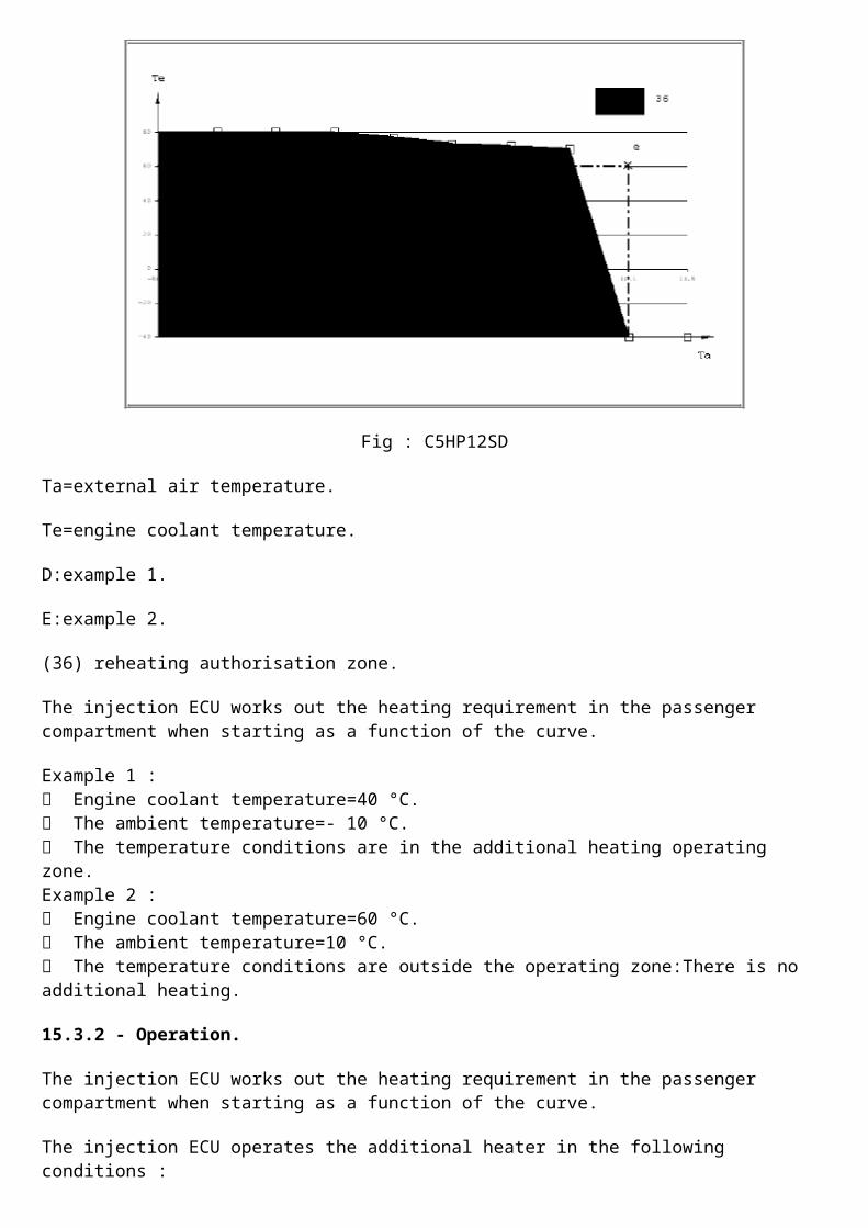
Fig : C5HP12SD
Ta=external air temperature.
Te=engine coolant temperature.
D:example 1.
E:example 2.
(36) reheating authorisation zone.
The injection ECU works out the heating requirement in the passenger compartment when starting as a function of the curve.
Example 1 : Engine coolant temperature=40 °C. The ambient temperature=- 10 °C. The temperature conditions are in the additional heating operating zone.Example 2 : Engine coolant temperature=60 °C. The ambient temperature=10 °C. The temperature conditions are outside the operating zone:There is no additional heating.
15.3.2 - Operation.
The injection ECU works out the heating requirement in the passenger compartment when starting as a function of the curve.
The injection ECU operates the additional heater in the following conditions : Engine operating for 60 seconds. Engine speed greater than 700 rpm. Battery voltage greater than 12 volts (positive electrical balance). Coolant temperature above - 40°C.
Initially, the injection ECU controls the first reheating stage and then the second stage after a 20 second timer.
The additional heating is switched off when the temperature conditions so allow (curve).
16 - Air conditioning compressor cut-out
The refrigeration is cut off by the injection ECU.
The injection ECU is connected to the following components : A pressure switch stage located in the air conditioning circuit. Engine coolant temperature sensor.
16.1 - Synopsis.
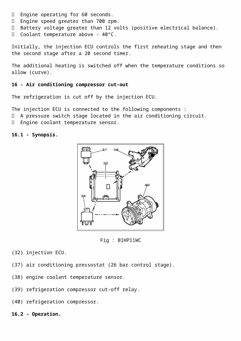
Fig : B1HP11WC
(32) injection ECU.
(37) air conditioning pressostat (26 bar control stage).
(38) engine coolant temperature sensor.
(39) refrigeration compressor cut-off relay.
(40) refrigeration compressor.
16.2 - Operation.
The ECU can cut off the supply of the electromagnetic clutch from the cooling compressor in the following cases : Engine speed less than 750 rpm. Coolant temperature greater than 115°C. Pressure in the air conditioning circuit greater than 26 bar.
17 - Engine immobiliser function
The injection ECU prevents the engine from starting by preventing injection.
Operating principle of the device:refer to the relevant documentation.
17.1 - Unlocking the system.
Every time the ignition is switched on, the authenticity of the keys is checked by one of the following systems (according to model) : Body computer (CPH). Transponder module.
17.2 - Locked with ignition off.
The injection ECU is automatically locked in the following cases : After the ignition has been switched off, 10 seconds after the driver's door is opened. A maximum of 10 minutes after the ignition is switched off.Operation stages : The engine immobiliser system wakes up the injection ECU via channel 66 of the connector.
Wake-up signal detected by the injection ECU. The injection ECU controls the supply to the first stage of the double injection relay. The injection ECU can talk with the CPH. The CPH sends the locking order. The injection ECU locks itself and cuts the supply to the double relay (1st stage).
17.3 - Procedure for replacing parts.
See chapter:repairs.
18 - Displaying faults-Back-up operating modes
18.1 - Displaying faults.
The appearance of certain faults in the injection system leads to the engine management lamp illuminating.
The engine management lamp illuminates if there is a fault on the following items or information : Voltage of capacitor N°1 (diesel injector control stage in the injection ECU). Voltage of capacitor N°2 (diesel injector control stage in the injection ECU). Fuel high pressure sensor. Pressure monitoring loop in the common injection rail. Accelerator pedal sensor (stage N° 1). Accelerator pedal sensor (stage N° 2). Boost pressure sensor. Air flowmeter. Supply sensor N°1. Supply sensor N°2. Exhaust gas recycling function (regulation). Boost pressure regulation electrovalve. Fuel high pressure regulator. Diesel injector fault (1 to 4).
18.2 - Back-up operating modes.
The injection system manages the following back-up modes : An operating mode with a reduced fuel flow. The other mode leads to the engine being stopped immediately.
18.2.1 - Reduced fuel flow.
This back-up operating mode limits fuel flow, and the engine speed cannot under any circumstances exceed 3200 rpm.
The injection system switches to "reduced flow" mode when a fault is present on one of the following components : Fuel high pressure sensor. Pressure monitoring loop in the common injection rail. Accelerator pedal sensor (stage N° 1). Accelerator pedal sensor (stage N° 2). Inlet manifold pressure sensor. Air flowmeter. Vehicle speed sensor. Exhaust gas recycling function (regulation). Recycling regulation electrovalve (EGR). Fuel high pressure regulator.
18.2.2 - Cut off airconditioning compressor.
The injection ECU causes the supply to the air conditioning clutch to be cut if a fault is detected on the fan unit control relay coils.
18.3 - Deactivator of the 3rd piston of the high pressure fuel pump.
When the fuel temperature is above 106°C, the injection ECU deactivates the 3rd piston of the high pressure pump (deactivator supplied).
18.4 - Engine stopped.
The systems causes the engine to stop immediately when a fault is present on one of the following components : Eprom in the injection ECU. Motor speed sensor. Camshaft position sensor. Voltage of capacitor N°1 (diesel injector control stage in the injection ECU). Voltage of capacitor N°2 (diesel injector control stage in the injection ECU). Pressure monitoring loop in the common injection rail. Diesel injector fault (1 to 4).
19 - Driver's information function
19.1 - Diagnostic warning lamp.
Normal operation of the warning lamp : The lamp illuminates when the ignition is switched on. The warning lamp goes off after time delay of 3 seconds.Warning lamp not operating as normal : The lamp illuminates when the ignition is switched on. The warning lamp remains on.
19.2 - Tachometer signal.
The injection ECU sends the engine speed signal to the control panel in the form of voltage pulses.
19.3 - Instantaneous fuel consumption signal.
The injection ECU sends the instantaneous consumption information in the form of pulses to the on board computer.
19.4 - Preheating warning lamp (V1150).
Normal operation of the warning lamp : Warning lamp illuminates during preheating (20 seconds maximum). Warning lamp goes out at the end of preheating.
19.5 - Engine coolant temperature warning lamp.
The coolant temperature warning lamp can be controlled by one of the following components : Injection ECU. Water temperature sensor (3-way).Normal operation of the warning lamp : The warning lamp illuminates if the temperature exceeds 118°C. The warning lamp goes out if the temperature falls below 117°C.
The warning lamp flashes if there is a break in the wiring of the coolant temperature sensor.
FUNCTION : FUEL SUPPLY
FOR 1C2X AND B0F7C AND DVY01 AND SINCE O 8001 OR
FOR 1CN6 AND B0F2X AND DVY01 AND SINCE O 8211 TO O 8687 OR
FOR 1CN7 AND B0F2X AND DVY01 AND SINCE O 8688 OR
FOR 1CX4 AND B0F2X AND DVY01 AND SINCE O 8688 OR
FOR 1CX4 AND B0F7C AND DVY01 AND SINCE O 8688 OR
FOR 1CU6 AND B0F7C AND DVY01 AND SINCE O 8276 OR
FOR 2CM4 AND B0F2X AND DVY01 AND SINCE O 8358 OR
FOR 1C6N AND B0F2X AND DVY01 AND SINCE O 8365 OR
FOR 2CU6 AND B0F7C AND DVY01 AND SINCE O 8421 OR
FOR 2CU6 AND B0F7U AND DVY01 AND SINCE O 8421
1 - Synopsis
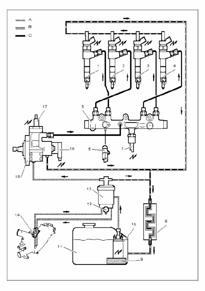
Fig : B1HP10QP
Index : A Fuel tank return circuit. B Low pressure fuel circuit. C High pressure fuel circuit.
Marked DescriptionPart number in the electrical diagrams
16High pressure fuel regulator on high pressure fuel pump
1322
17Deactivator of the 3rd piston of the high pressure fuel pump
1208-6
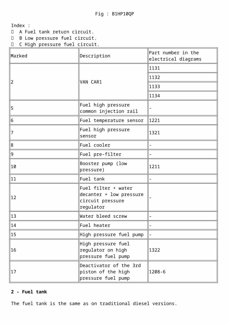
2 - Fuel tank
The fuel tank is the same as on traditional diesel versions.
3 - Booster pump (low pressure) (1211)(1211)
3.1 - Role.
Role of the booster pump : To supply fuel to the high pressure pump. To provide the pressure required in the low pressure circuit.
3.2 - Description.
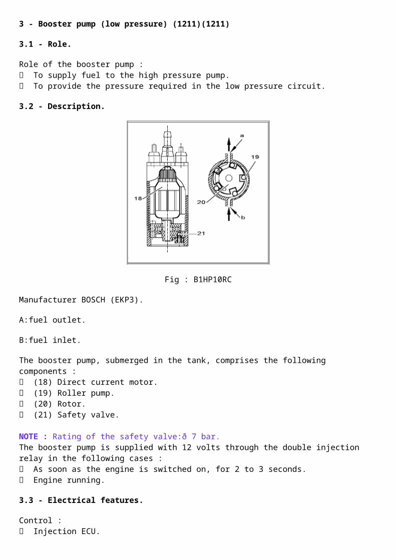
Fig : B1HP10RC
Manufacturer BOSCH (EKP3).
A:fuel outlet.
B:fuel inlet.
The booster pump, submerged in the tank, comprises the following components : (18) Direct current motor. (19) Roller pump. (20) Rotor. (21) Safety valve.
NOTE : Rating of the safety valve:ð 7 bar. The booster pump is supplied with 12 volts through the double injection relay in the following cases : As soon as the engine is switched on, for 2 to 3 seconds. Engine running.
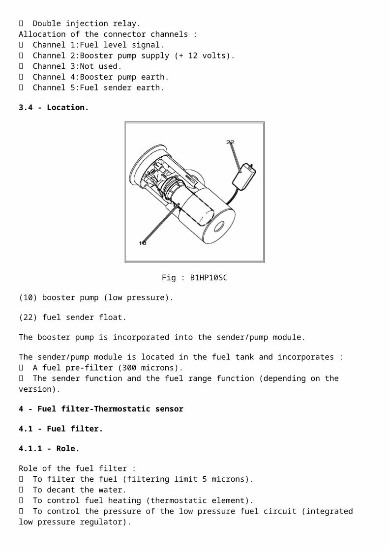
The booster pump is incorporated into the sender/pump module.
The sender/pump module is located in the fuel tank and incorporates : A fuel pre-filter (300 microns). The sender function and the fuel range function (depending on the version).
4 - Fuel filter-Thermostatic sensor
4.1 - Fuel filter.
4.1.1 - Role.
Role of the fuel filter : To filter the fuel (filtering limit 5 microns). To decant the water. To control fuel heating (thermostatic element). To control the pressure of the low pressure fuel circuit (integrated low pressure regulator).
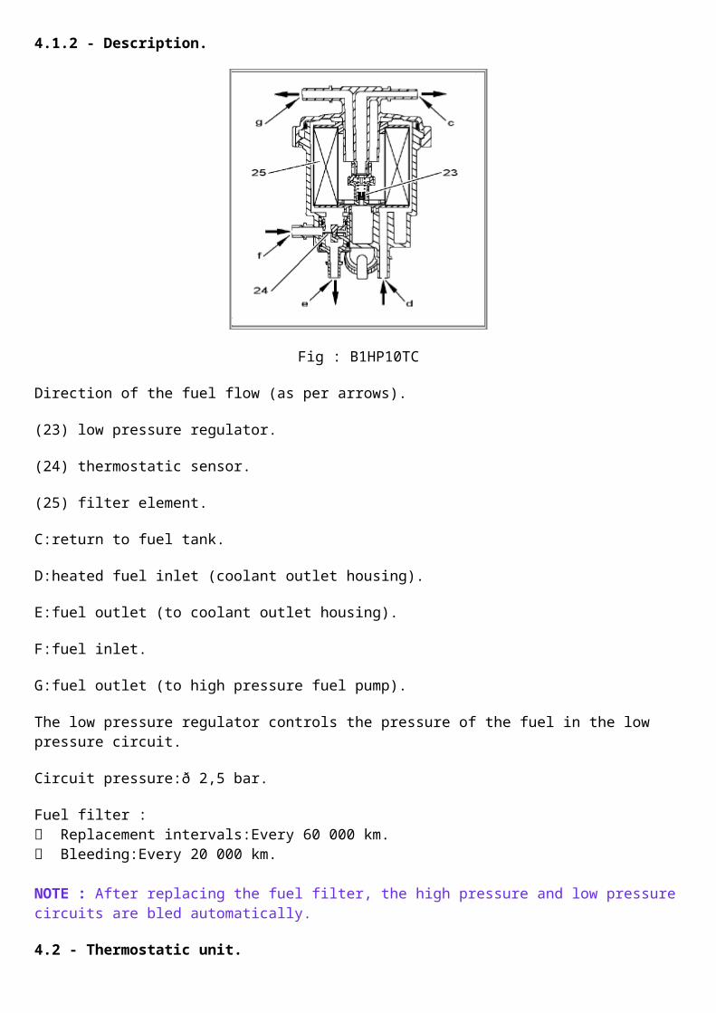
4.1.2 - Description.
Fig : B1HP10TC
Direction of the fuel flow (as per arrows).
(23) low pressure regulator.
(24) thermostatic sensor.
(25) filter element.
C:return to fuel tank.
D:heated fuel inlet (coolant outlet housing).
E:fuel outlet (to coolant outlet housing).
F:fuel inlet.
G:fuel outlet (to high pressure fuel pump).
The low pressure regulator controls the pressure of the fuel in the low pressure circuit.
Circuit pressure:ð 2,5 bar.
Fuel filter : Replacement intervals:Every 60 000 km. Bleeding:Every 20 000 km.
NOTE : After replacing the fuel filter, the high pressure and low pressure circuits are bled automatically.
4.2 - Thermostatic unit.
4.2.1 - Role.
When cold, the thermostatic element diverts some of the fuel to the fuel heater.
When warm, the thermostatic element prevents fuel from being heated.
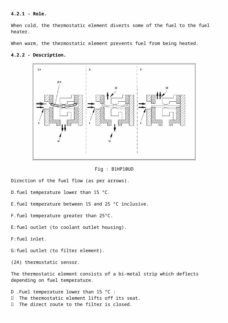
4.2.2 - Description.
Fig : B1HP10UD
Direction of the fuel flow (as per arrows).
D.fuel temperature lower than 15 °C.
E.fuel temperature between 15 and 25 °C inclusive.
F.fuel temperature greater than 25°C.
E:fuel outlet (to coolant outlet housing).
F:fuel inlet.
G:fuel outlet (to filter element).
(24) thermostatic sensor.
The thermostatic element consists of a bi-metal strip which deflects depending on fuel temperature.
D .Fuel temperature lower than 15 °C : The thermostatic element lifts off its seat. The direct route to the filter is closed. The fuel is heated when in contact with the coolant outlet housing.E .Fuel temperature between 15 and 25 °C inclusive : The thermostatic element is partially lifted off its seat. Part of the fuel is heated.F .Fuel temperature greater than 25°C : The thermostatic element is resting on its seat. The fuel passes directly to the filter.
5 - Fuel heater
5.1 - Role.
The fuel heater raises the fuel to its working temperature.
5.2 - Description.
The fuel heater heats the fuel diverted by the thermostatic element (fuel filter).
The fuel heater consists of a tube submerged in the engine coolant.
Heat is exchanged between the coolant and the fuel.
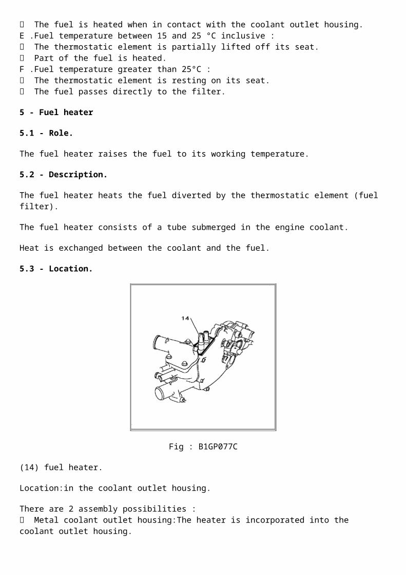
5.3 - Location.
Fig : B1GP077C
(14) fuel heater.
Location:in the coolant outlet housing.
There are 2 assembly possibilities : Metal coolant outlet housing:The heater is incorporated into the coolant outlet housing. Plastic coolant outlet housing:The heater is secured to the coolant outlet housing.
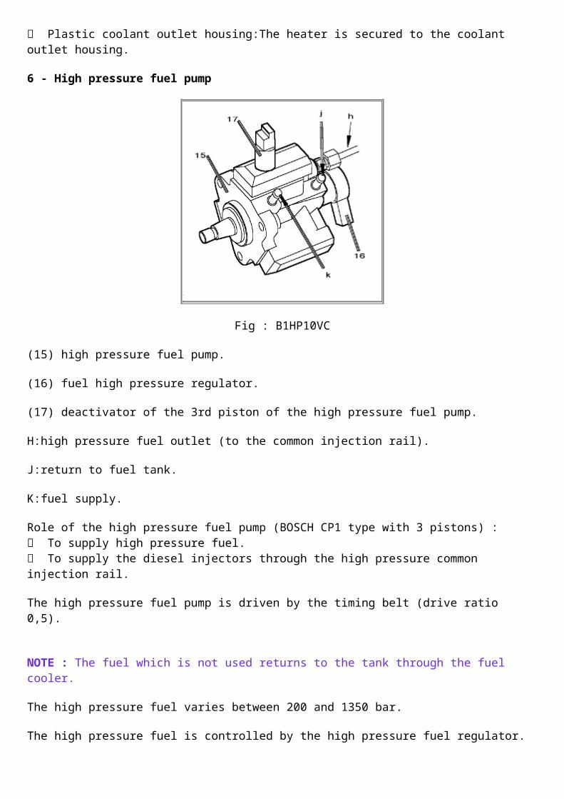
6 - High pressure fuel pump
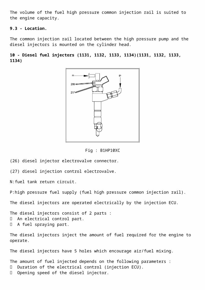
Fig : B1HP10VC
(15) high pressure fuel pump.
(16) fuel high pressure regulator.
(17) deactivator of the 3rd piston of the high pressure fuel pump.
H:high pressure fuel outlet (to the common injection rail).
J:return to fuel tank.
K:fuel supply.
Role of the high pressure fuel pump (BOSCH CP1 type with 3 pistons) : To supply high pressure fuel. To supply the diesel injectors through the high pressure common injection rail.
The high pressure fuel pump is driven by the timing belt (drive ratio 0,5).
NOTE : The fuel which is not used returns to the tank through the fuel cooler.
The high pressure fuel varies between 200 and 1350 bar.
The high pressure fuel is controlled by the high pressure fuel regulator.
When starting the engine, after 1,5 engine revolutions, the pressure supplied by the pump reaches 200 bar.
NOTE : The high pressure pump is not a distributing pump and does not need setting. The deactivator of the 3rd piston of the high pressure fuel pump is used to reduce : The capacity of the high pressure fuel pump. The power absorbed by the high pressure fuel pump.
7 - Deactivator of the 3rd piston of the high pressure fuel pump (1208-6)(1208-6)
7.1 - Role.
To reduce the power absorbed by the high pressure pump if the vehicle is used at low load.
Whilst this component is being operated, the amount of fuel delivered decreases which reduces : The power absorbed by the high pressure fuel pump. The amount the fuel heats up (less laminating).
NOTE : If the fuel temperature exceeds 106 °C, the high pressure fuel pump only operates on 2 pistons.
7.2 - Location.
Location:on the high pressure fuel pump.
8 - Fuel high pressure regulator (1322)(1322)
8.1 - Role.
The high pressure fuel regulator regulates the pressure of the fuel at the outlet of the high pressure fuel pump.
8.2 - Location.
Location:on the high pressure fuel pump.
9 - Fuel high pressure common injection rail
9.1 - Role.
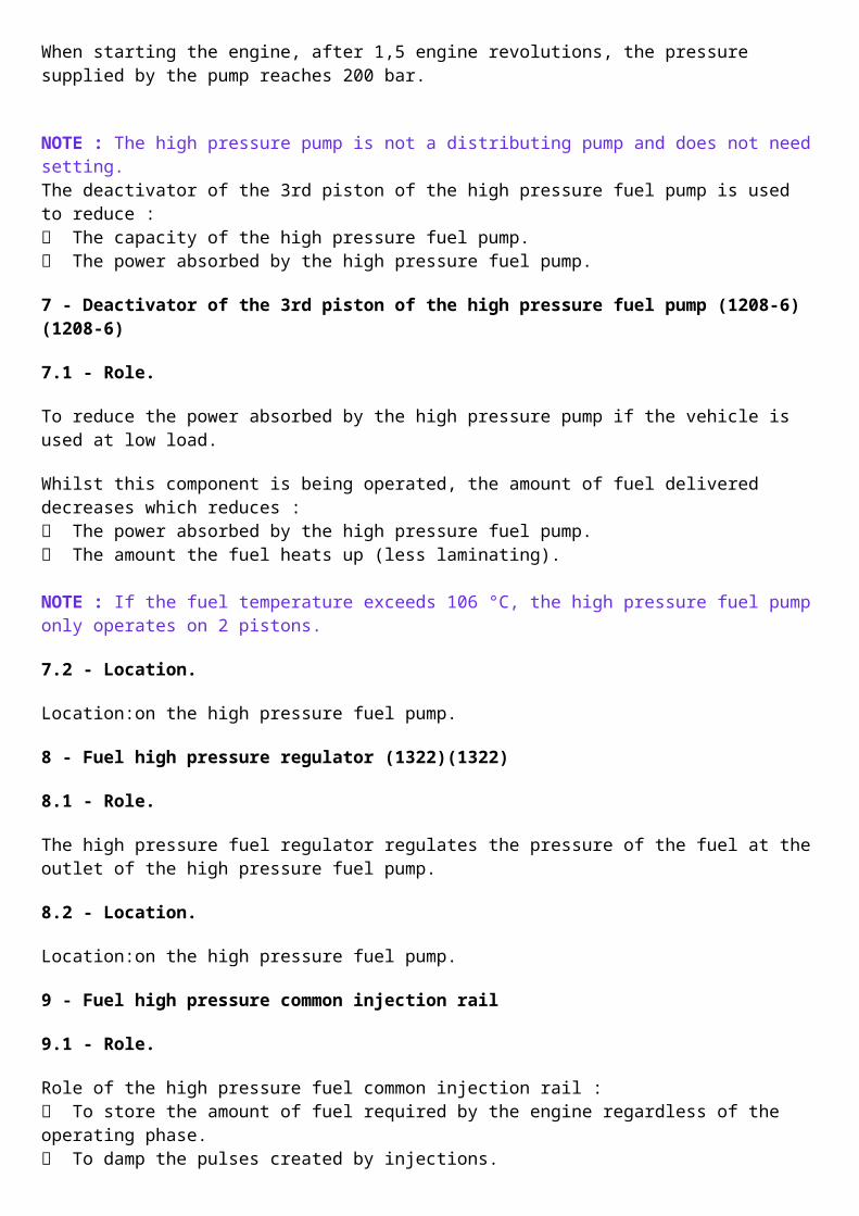
Role of the high pressure fuel common injection rail : To store the amount of fuel required by the engine regardless of the operating phase. To damp the pulses created by injections. To connect the components of the high pressure circuit.Components connected to the fuel high pressure common injection rail : High pressure fuel supply pipe. Diesel injector supply pipes. Fuel temperature sensor. Fuel high pressure sensor.
IMPORTANT : Use a regularly checked torque wrench to ensure the correct tightening torques for the following components of the high pressure circuit.
Diesel fuel injectors.
Fuel high pressure sensor.
High pressure fuel pipes.
9.2 - Description.
Fig : B1HP10WC
(5) fuel high pressure common injection rail.
(6) fuel temperature sensor.
(7) fuel high pressure sensor.
L:outlets to diesel injectors.
M:high pressure fuel supply.
NOTE : The high pressure fuel common injection rail is made from forged steel.
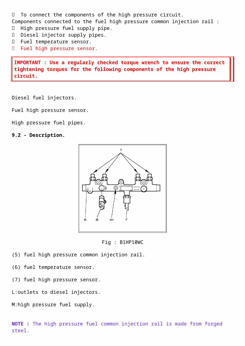
The volume of the fuel high pressure common injection rail is suited to the engine capacity.
9.3 - Location.
The common injection rail located between the high pressure pump and the diesel injectors is mounted on the cylinder head.
P:high pressure fuel supply (fuel high pressure common injection rail).
The diesel injectors are operated electrically by the injection ECU.
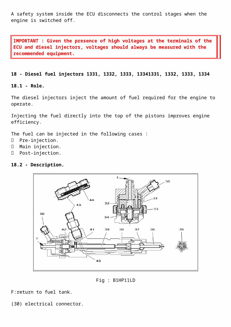
The diesel injectors consist of 2 parts : An electrical control part. A fuel spraying part.
The diesel injectors inject the amount of fuel required for the engine to operate.
The diesel injectors have 5 holes which encourage air/fuel mixing.
The amount of fuel injected depends on the following parameters : Duration of the electrical control (injection ECU). Opening speed of the diesel injector. Hydraulic flow of the diesel injector (number and diameter of holes). Fuel pressure in the fuel high pressure common injection rail.The fuel can be injected in the following cases : Pre-injection. Main injection.
Post-injection.
The diesel injectors are connected together by the fuel return circuit.
Fuel pressure in the return circuit:ð 0,7 bar.
11 - Fuel cooler
11.1 - Role.
The high pressure pump laminates the fuel from the booster pump which increases the fuel temperature.
The fuel cooler cools the fuel as it returns to the tank.
11.2 - Description.
The fuel cooler consists of a metal coil which encourages heat exchange between the fuel and the air.
11.3 - Location.
The fuel cooler is located under the body.
FUNCTION : HDI DIRECT INJECTION SYSTEM
FOR 1C2X AND B0F7C AND DVY01 AND SINCE O 8001 OR
FOR 1CN6 AND B0F2X AND DVY01 AND SINCE O 8211 TO O 8688 OR
FOR 1CN7 AND B0F2X AND DVY01 AND SINCE O 8688 OR
FOR 1CX4 AND B0F2X AND DVY01 AND SINCE O 8688 OR
FOR 1CX4 AND B0F7C AND DVY01 AND SINCE O 8688 OR
FOR 1CU6 AND B0F7C AND DVY01 AND SINCE O 8276 OR
FOR 2CM4 AND B0F2X AND DVY01 AND SINCE O 8358 OR
FOR 1C6N AND B0F2X AND DVY01 AND SINCE O 8365 OR
FOR 2CU6 AND B0F7C AND DVY01 AND SINCE O 8421 OR
FOR 2CU6 AND B0F7U AND DVY01 AND SINCE O 8421
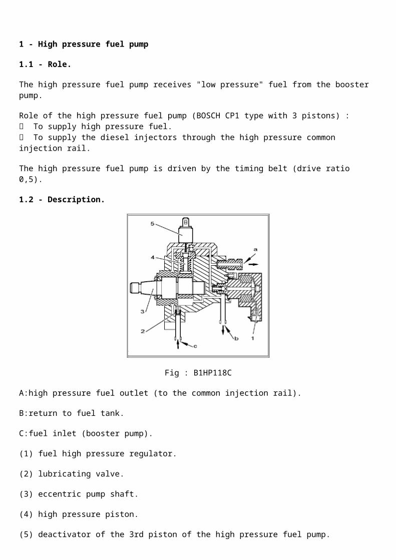
1 - High pressure fuel pump
1.1 - Role.
The high pressure fuel pump receives "low pressure" fuel from the booster pump.
Role of the high pressure fuel pump (BOSCH CP1 type with 3 pistons) : To supply high pressure fuel. To supply the diesel injectors through the high pressure common injection rail.
The high pressure fuel pump is driven by the timing belt (drive ratio 0,5).
1.2 - Description.
Fig : B1HP118C
A:high pressure fuel outlet (to the common injection rail).
B:return to fuel tank.
C:fuel inlet (booster pump).
(1) fuel high pressure regulator.
(2) lubricating valve.
(3) eccentric pump shaft.
(4) high pressure piston.
(5) deactivator of the 3rd piston of the high pressure fuel pump.
The high pressure fuel varies between 200 and 1350 bar.
NOTE : The high pressure fuel is controlled by the high pressure fuel regulator. Components mounted on the high pressure fuel pump : (1) Fuel high pressure regulator. (5) Deactivator of the 3rd piston of the high pressure fuel pump.
NOTE : The high pressure pump is not a distributing pump and does not need setting.
Maximum absorbed power:3,5kW.
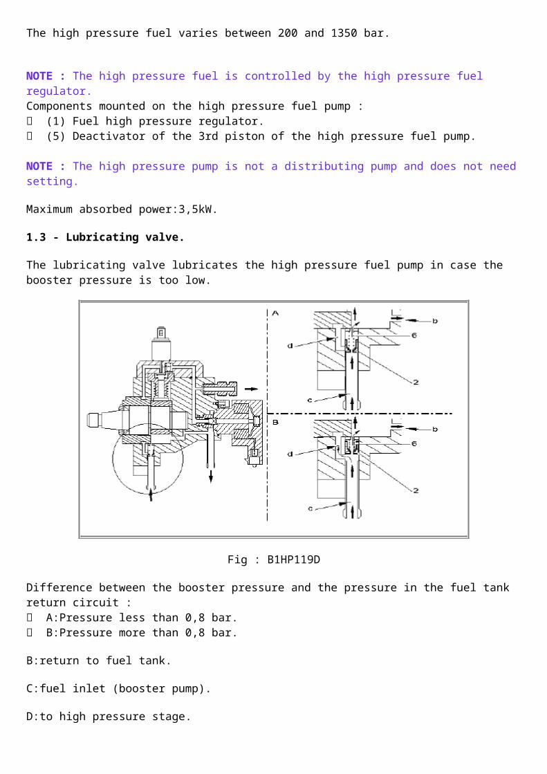
1.3 - Lubricating valve.
The lubricating valve lubricates the high pressure fuel pump in case the booster pressure is too low.
Fig : B1HP119D
Difference between the booster pressure and the pressure in the fuel tank return circuit : A:Pressure less than 0,8 bar. B:Pressure more than 0,8 bar.
B:return to fuel tank.
C:fuel inlet (booster pump).
D:to high pressure stage.
(2) lubricating valve.
(6) return spring.
The fuel enters the pump through inlet "c" and passes through the lubrication valve (2) (booster pump).
A :Pressure less than 0,8 bar : The fuel pressure is not sufficient to push back the valve (2). The fuel passes through the valve (restrictor hole). The fuel lubricates and cools the high pressure pump.B :Pressure more than 0,8 bar : The fuel pushes back the valve (2). The fuel used for lubricating passes through the valve through its restriction. The fuel is distributed to the high pressure stage "d" of the high pressure pump.
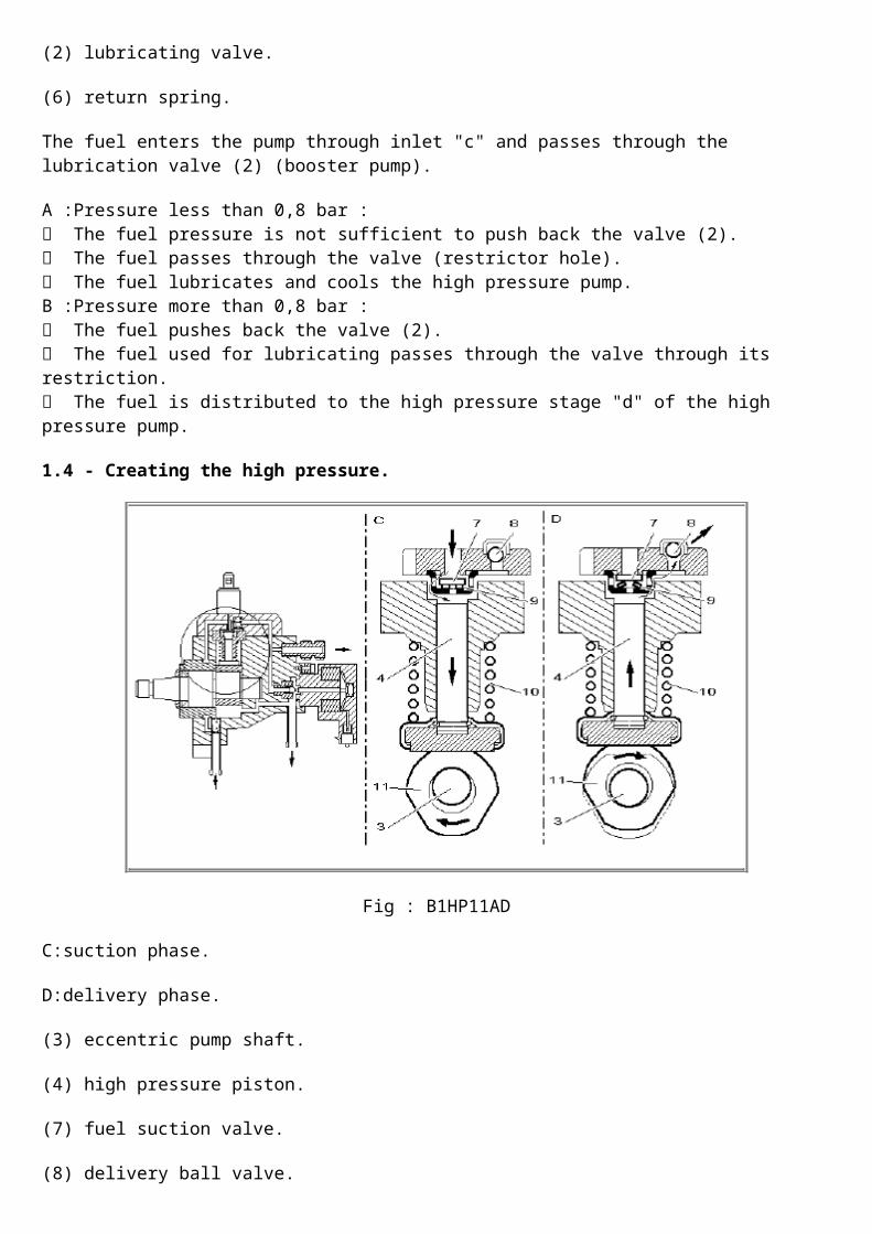
1.4 - Creating the high pressure.
Fig : B1HP11AD
C:suction phase.
D:delivery phase.
(3) eccentric pump shaft.
(4) high pressure piston.
(7) fuel suction valve.
(8) delivery ball valve.
(9) suction valve return spring.
(10) high pressure piston return spring.
(11) drive cam.
The shaft of the high pressure fuel pump contains a cam.
The injection pistons are supplied with fuel by the low pressure circuit inside the high pressure pump.
The fuel is drawn in by the piston during the suction phase.
C Suction phase : The booster pump supplies fuel through the suction valve (7). The return spring pushes the piston back against the cam. The piston creates a vacuum in the liner.D Delivery phase : After bottom dead centre. The drop in fuel pressure causes the suction valve to close (approximately 1 bar). The fuel is blocked in the chamber. The cam of the high pressure fuel pump pushes the piston. The fuel pressure increases. The fuel is delivered to the delivery valve.
The delivery valve (8) opens.
After top dead centre, the delivery valve closes following the reduction in pressure.
2 - Deactivator of the 3rd piston of the high pressure fuel pump (1208-6)(1208-6)
2.1 - Role.
Role of the deactivator of the 3rd piston of the high pressure fuel pump : To reduce the power absorbed by the high pressure pump if the vehicle is used at low load. To limit the high pressure quickly in the event of a problem.
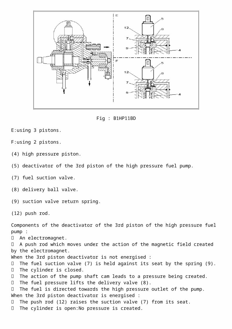
2.2 - Description.
Fig : B1HP11BD
E:using 3 pistons.
F:using 2 pistons.
(4) high pressure piston.
(5) deactivator of the 3rd piston of the high pressure fuel pump.
(7) fuel suction valve.
(8) delivery ball valve.
(9) suction valve return spring.
(12) push rod.
Components of the deactivator of the 3rd piston of the high pressure fuel pump : An electromagnet. A push rod which moves under the action of the magnetic field created by the electromagnet.When the 3rd piston deactivator is not energised : The fuel suction valve (7) is held against its seat by the spring (9).
The cylinder is closed. The action of the pump shaft cam leads to a pressure being created. The fuel pressure lifts the delivery valve (8). The fuel is directed towards the high pressure outlet of the pump.When the 3rd piston deactivator is energised : The push rod (12) raises the suction valve (7) from its seat. The cylinder is open:No pressure is created. The fuel is directed towards the low pressure part of the high pressure pump.
2.3 - Electrical features.
Control:injection ECU.
Type:"all or nothing" control through earth.
When the 3rd piston deactivator is energised:the pump operates on 2 pistons.
When the 3rd piston deactivator is not energised:the pump operates on 3 pistons.
3 - Fuel high pressure regulator (1322)(1322)
3.1 - Role.
The high pressure fuel regulator regulates the pressure of the fuel at the outlet of the high pressure fuel pump.
3.2 - Description.
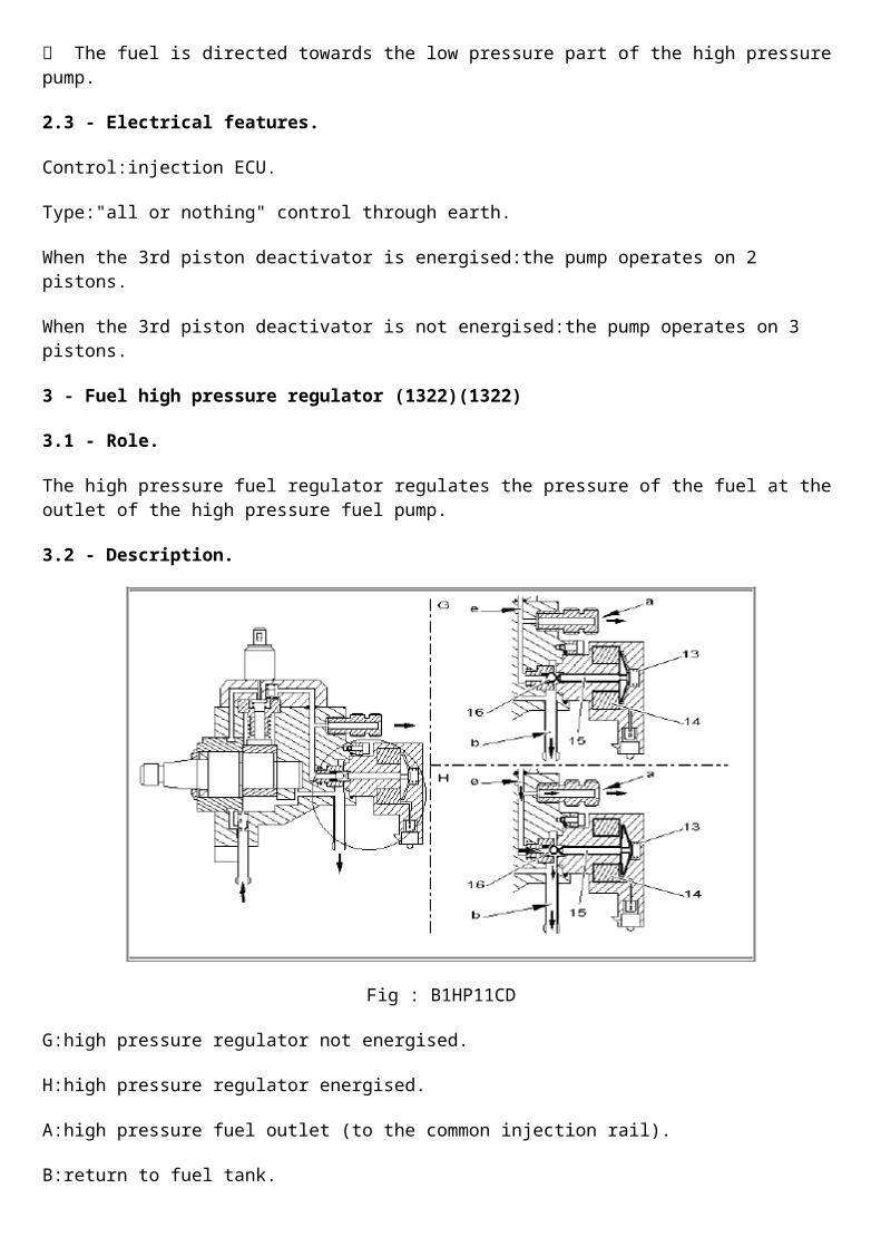
Fig : B1HP11CD
G:high pressure regulator not energised.
H:high pressure regulator energised.
A:high pressure fuel outlet (to the common injection rail).
B:return to fuel tank.
E:high pressure fuel circuit.
(13) spring.
(14) electric coil.
(15) magnetic core.
(16) ball.
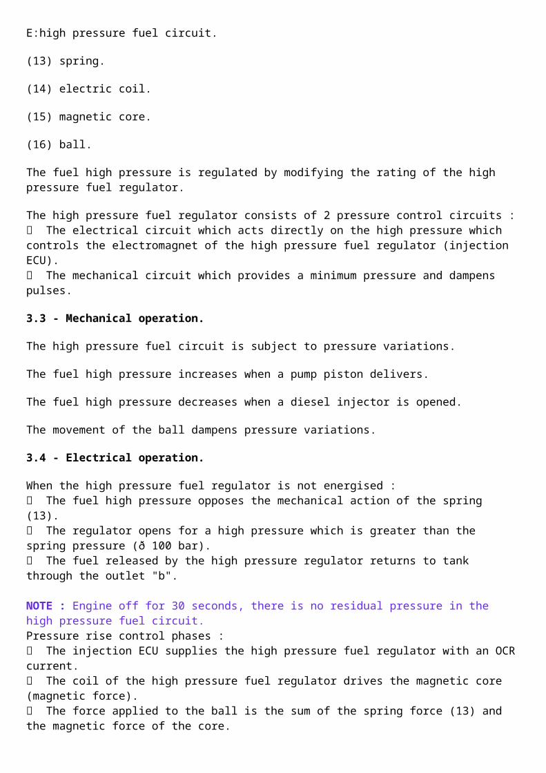
The fuel high pressure is regulated by modifying the rating of the high pressure fuel regulator.
The high pressure fuel regulator consists of 2 pressure control circuits : The electrical circuit which acts directly on the high pressure which controls the electromagnet of the high pressure fuel regulator (injection ECU). The mechanical circuit which provides a minimum pressure and dampens pulses.
3.3 - Mechanical operation.
The high pressure fuel circuit is subject to pressure variations.
The fuel high pressure increases when a pump piston delivers.
The fuel high pressure decreases when a diesel injector is opened.
The movement of the ball dampens pressure variations.
3.4 - Electrical operation.
When the high pressure fuel regulator is not energised : The fuel high pressure opposes the mechanical action of the spring (13). The regulator opens for a high pressure which is greater than the spring pressure (ð 100 bar). The fuel released by the high pressure regulator returns to tank through the outlet "b".
NOTE : Engine off for 30 seconds, there is no residual pressure in the high pressure fuel circuit. Pressure rise control phases : The injection ECU supplies the high pressure fuel regulator with an OCR current. The coil of the high pressure fuel regulator drives the magnetic core (magnetic force). The force applied to the ball is the sum of the spring force (13) and the magnetic force of the core. The cut-out value of the high pressure regulator increases.Pressure reduction control phases : The injection ECU reduces the OCR supplied to the coil of the high pressure fuel regulator. The coil of the high pressure fuel regulator drives the magnetic core (magnetic force). The force applied to the ball reduces. The cut-off valve of the high pressure regulator decreases.
NOTE : OCR : Open Cycle Ratio.
3.5 - Electrical features.
When the high pressure fuel regulator is not energised:the pressure is limited to ð 100 bar.
Control:injection ECU (earth).
Variable voltage control (OCR) : Maximum voltage (maximum OCR)=Maximum pressure.
Minimum voltage (minimum OCR)=Minimum pressure.
IMPORTANT : After switching off the engine, wait for 30 seconds before starting any repair work.
4 - Fuel high pressure common injection rail
4.1 - Role.
The fuel high pressure common injection rail acts as a fuel accumulator.
The fuel is available for all diesel injectors.
4.2 - Description.
Components connected to the fuel high pressure common injection rail : High pressure fuel supply pipe. Diesel injector supply pipes. Fuel temperature sensor. Fuel high pressure sensor.
The volume of the fuel high pressure common injection rail is suited to the engine capacity.
5 - Battery (BB00)BB00
The charge level of the battery is important for the HDI direct injection system to operate.
WARNING : A battery voltage of less than 10 volts disturbs the operation of the HDI direct injection system. The ECU memorises a fault in the following cases : Battery voltage greater than 17,5 volts. Battery voltage less than 7 volts.
6 - Double injection relay (1304)1304
The double injection relay is controlled directly by the injection ECU.
The first relay of the double injection relay supplies the following components : Booster pump (low pressure). Boost pressure regulation electrovalve. Air flowmeter. Recycling regulation electrovalve (EGR).The second relay of the double injection relay supplies the following components : Injection ECU (power part). Control relay of the electric cooling fans.
NOTE : After switching off the ignition, the double injection relay remains energised for 4 seconds or for 6 minutes in the event of post-ventilation. During a request to unlock the injection ECU by the engine immobiliser system (specific ECU channel) : The ECU supplies the double injection relay. The ECU is re-supplied by the double injection relay (power). Dialogue between the injection ECU and the engine immobiliser system is possible. At the end of dialogue, the injection ECU cuts the supply to the double injection relay.
WARNING : The engine immobiliser system wakes up the injection ECU via channel 66 of the connector.
7 - Accelerator pedal sensor (1261)(1261)
7.1 - Role.
The sensor is linked to the accelerator pedal by a cable.
The wheel sensor : Records the driver's request (acceleration, decelaration). Sends information to injection ECU.
Using this information, the ECU works out the fuel flow to inject (time and injection pressure).
7.2 - Description.
Fig : B1HP11DC
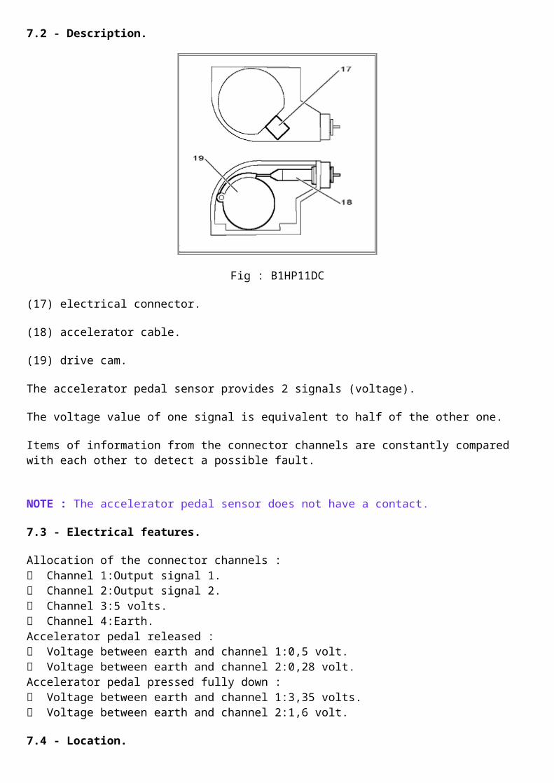
(17) electrical connector.
(18) accelerator cable.
(19) drive cam.
The accelerator pedal sensor provides 2 signals (voltage).
The voltage value of one signal is equivalent to half of the other one.
Items of information from the connector channels are constantly compared with each other to detect a possible fault.
NOTE : The accelerator pedal sensor does not have a contact.
7.3 - Electrical features.
Allocation of the connector channels : Channel 1:Output signal 1. Channel 2:Output signal 2. Channel 3:5 volts. Channel 4:Earth.Accelerator pedal released :
Voltage between earth and channel 1:0,5 volt. Voltage between earth and channel 2:0,28 volt.Accelerator pedal pressed fully down : Voltage between earth and channel 1:3,35 volts. Voltage between earth and channel 2:1,6 volt.
7.4 - Location.
In the engine compartment.
8 - Engine speed sensor (1313)(1313)
8.1 - Role.
The sensor is located opposite the teeth of the flywheel.
The sensor is used to work out the following parameters : Engine rpm. Position of removable coupling.
8.2 - Description.
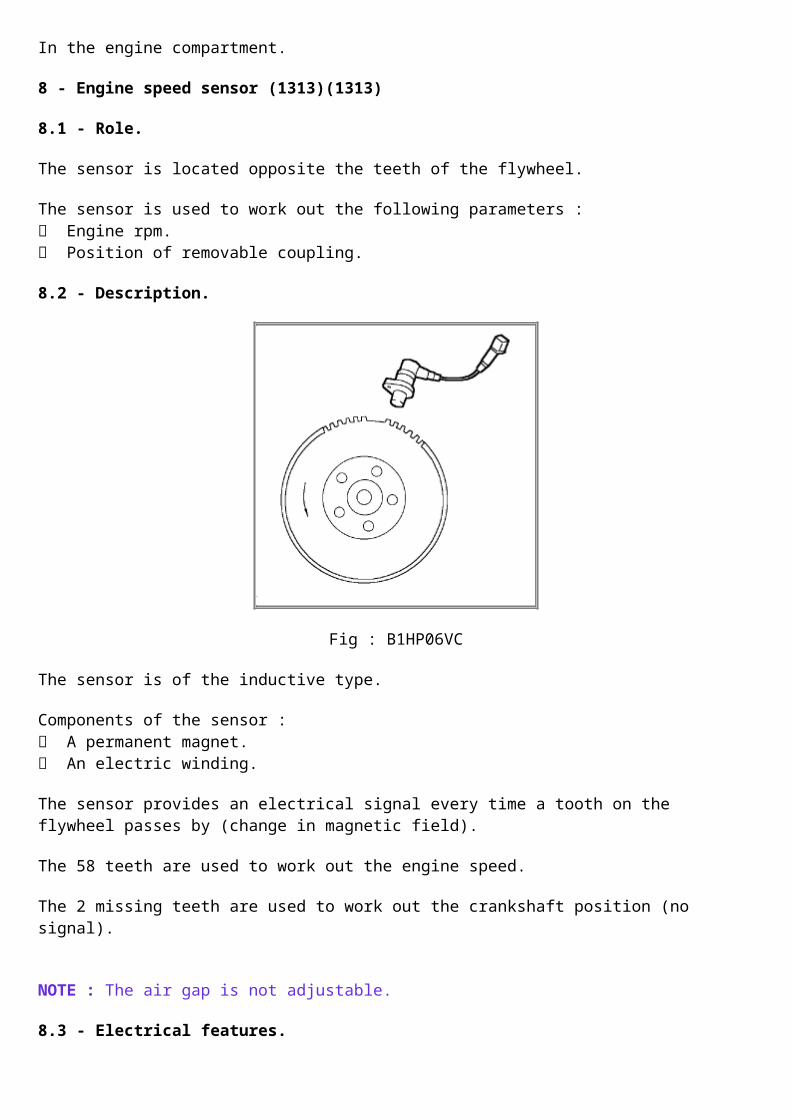
Fig : B1HP06VC
The sensor is of the inductive type.
Components of the sensor : A permanent magnet. An electric winding.
The sensor provides an electrical signal every time a tooth on the flywheel passes by (change in magnetic field).
The 58 teeth are used to work out the engine speed.
The 2 missing teeth are used to work out the crankshaft position (no signal).
NOTE : The air gap is not adjustable.
8.3 - Electrical features.
Allocation of the connector channels : Channel 1:Signal. Channel 2:Earth.
Resistance between channels 1 and 2:50 ohms.
Features of the signals emitted:variable frequency alternating voltage.
WARNING : The sensor wire is not screened, therefore always follow the correct harness route.
8.4 - Location.
Location:on the clutch housing.
9 - The camshaft position sensor (1115)1115
9.1 - Role.
Role of the injection ECU according to the data received : To synchronise fuel injections with respect to the position of the pistons. To recognise top dead centres.
9.2 - Description.
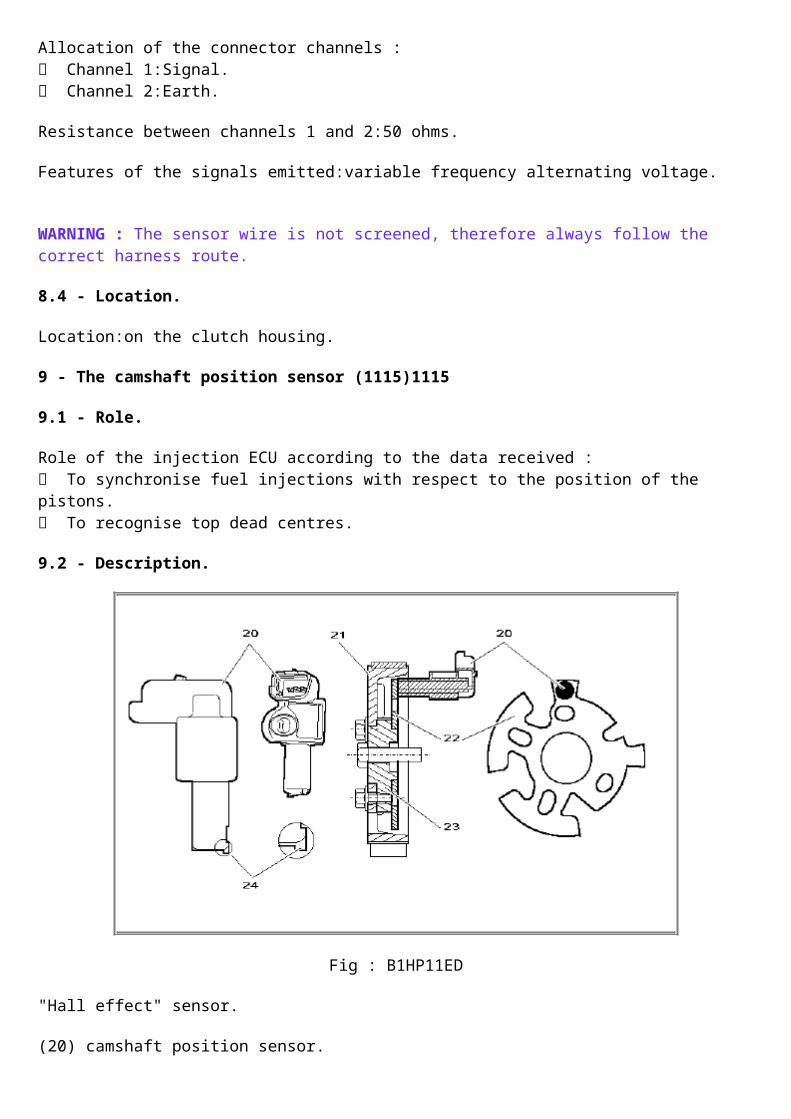
Fig : B1HP11ED
"Hall effect" sensor.
(20) camshaft position sensor.
(21) camshaft pulley.
(22) target driven by the camshaft.
(23) camshaft hub.
(24) plastic lug.
The camshaft sensor provides a square signal for the injection ECU.
The camshaft sensor is located opposite a target driven by the camshaft pulley.
The sensor is used to synchronise fuel injections with respect to piston position (sequential injection).
The plastic lug (24) is used to adjust the air gap in the factory.
NOTE : The plastic lug is destroyed the first time the engine is started.
IMPORTANT : When refitting a camshaft sensor, it is necessary to keep the gap between the sensors and target E = 1,2 (+0 ; +0,1) mm.
9.3 - Electrical features.
Air and fuel supply:injection ECU.
Allocation of the connector channels : Channel 1:5 volts supply. Channel 2:Signal. Channel 3:Earth.
The voltage slots are between 0 and 5 volts.
Signal emitted : Presence of metal earth opposite the sensor:0 volt. Absence of metal earth opposite the sensor:5 volts.
10 - Engine coolant temperature sensor (1220)(1220)
10.1 - Role.
The engine coolant temperature sensor informs the ECU about the engine coolant temperature.
Role of the injection ECU according to the data received : To adjust the preheating time. To adjust the postheating time. To adjust the starting flow. To adjust the idle speed. To authorise exhaust gas recycling (EGR). To adjust the fuel flow. To limit the flow injected if the temperature of the coolant is critical (anti-boil function). To operate the fans. To operate the logometer on the control panel (*). To operate the warning and prewarning lights (*).
NOTE : (*) according to model.
10.2 - Description.
There are 2 assembly possibilities :
3-way blue sensor. 2-way green sensor.
10.2.1 - 3-way blue sensor.
The sensor consists of 2 NTC (negative temperature coefficient resistor).
Allocation of the connector channels : Channel 1-Channel 2:NTC for the injection ECU. Channel 3-Earth:NTC for the gauge on the control panel.Electrical specifications : Channel 1-Channel 2:Resistance at 20 °C=6200 ohms. Channel 3-Earth:Resistance at 30 °C=1925 ohms.
10.2.2 - 2-way green sensor.
The sensor consists of a Negative Temperature Coefficient (NTC) resistor.
The higher the temperature, the greater its resistance.
Electrical specifications:resistance at 20 °C =6200 ohms.
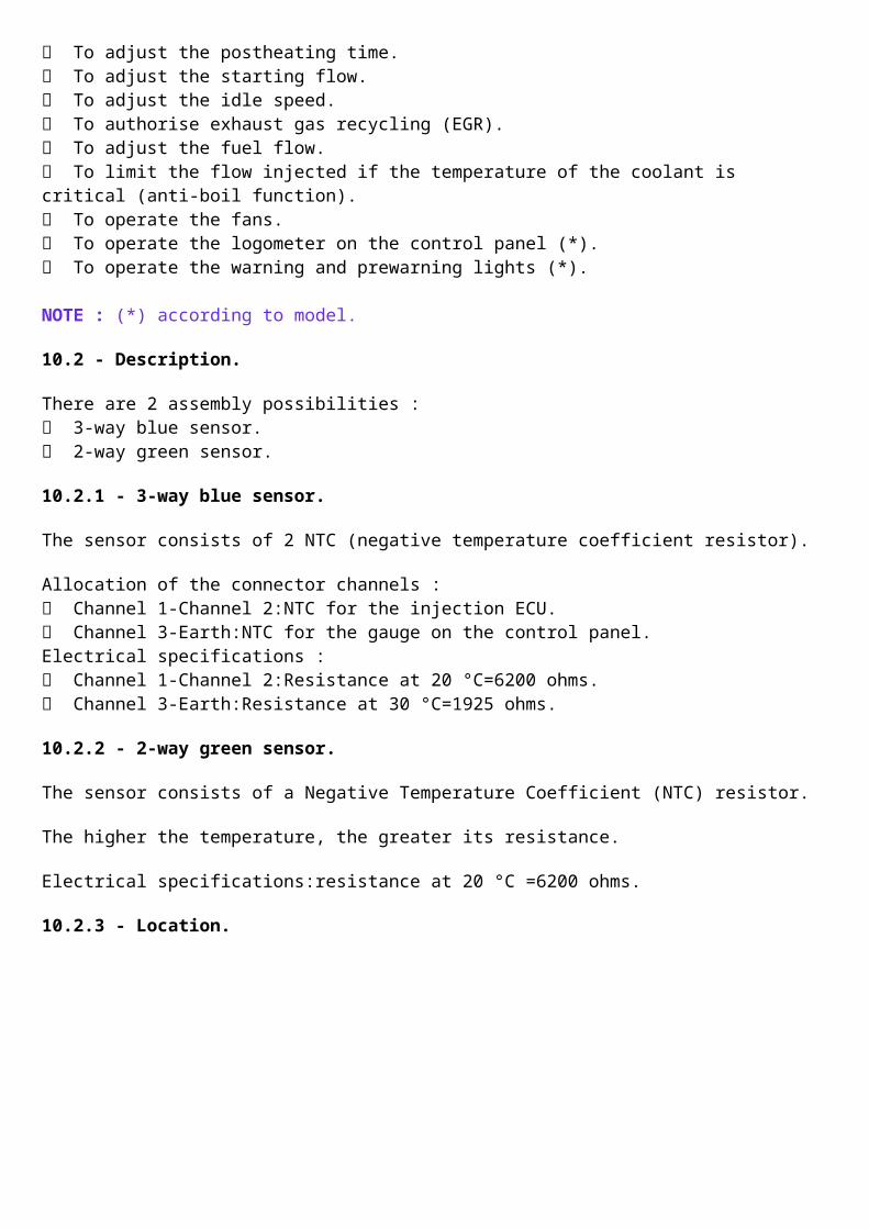
10.2.3 - Location.
Fig : B1GP078C
(25) engine coolant temperature sensor.
The water temperature sensor is fitted to the coolant unit.
There are 2 assembly possibilities.
Metal coolant outlet housing : The coolant temperature sensor is screwed in. It is sealed with a copper seal.Plastic coolant outlet housing : The coolant temperature sensor is secured by a plastic clip. It is sealed with an O-ring.
11 - Air temperature sensor (1310)(1310)
11.1 - Role.
The air temperature sensor informs the ECU about the temperature of the air taken in.
Role of the injection ECU according to the data received : To control the additional heating. To calculate the density of the ambient air.
WARNING : The air temperature probe is incorporated into the air flow meter.
11.2 - Description.
The sensor consists of a Negative Temperature Coefficient (NTC) resistor.
The more the temperature increases, the more its resistance value is reduced.
Electrical specifications:resistance at 25 °C =3300 ohms.
11.3 - Location.
Fig : B1HP11FC
(26) air temperature sensor.
The air temperature probe is incorporated into the air flow meter.
12 - Fuel temperature sensor (1221)(1221)
12.1 - Role.
Role of the injection ECU according to the data received : To adjust the fuel flow. To calculate the fuel density.
12.2 - Description.
Fig : B1HP11GC
The sensor consists of a Negative Temperature Coefficient (NTC) resistor.
A variation of this assembly measures the fuel temperature directly on the return to tank circuit : Resistance at 25 °C=2400 ohms. Resistance at 80 °C=270 ohms.
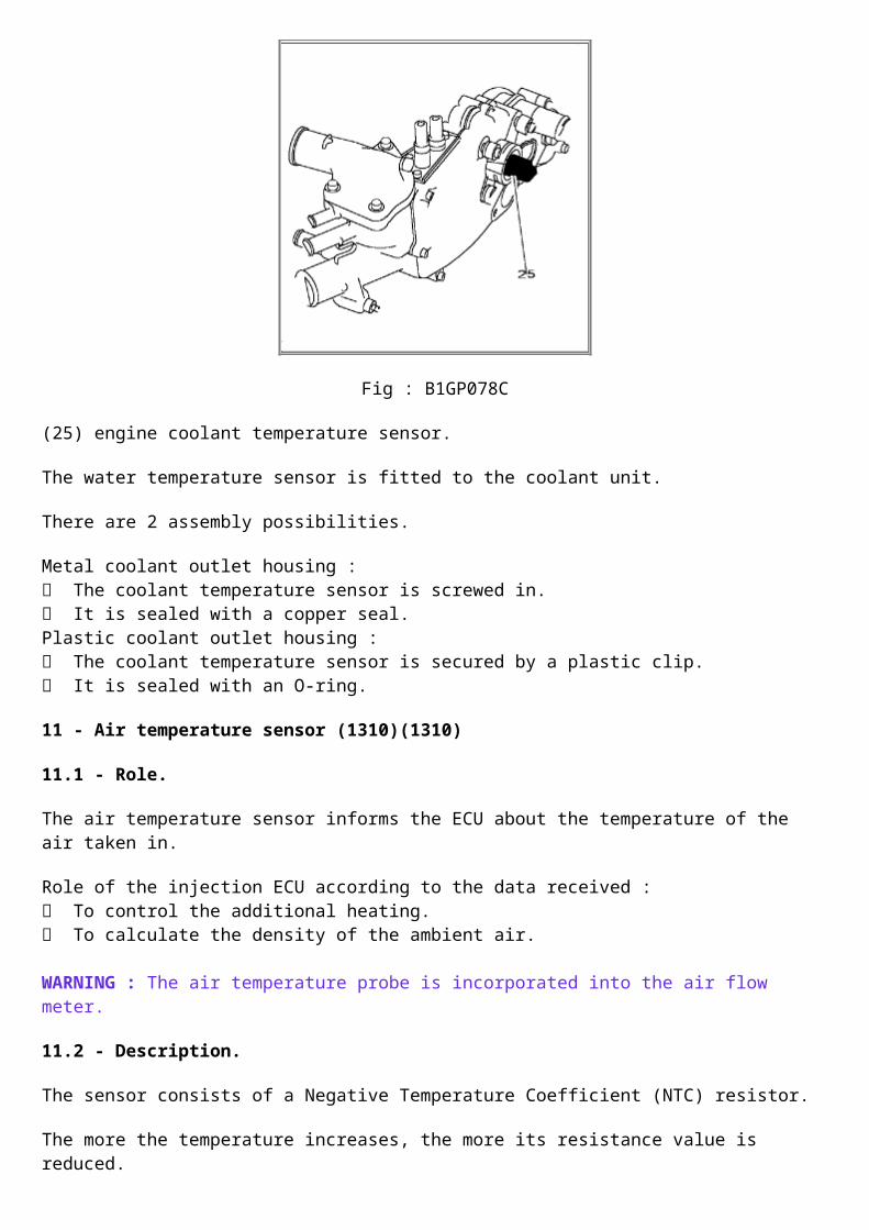
12.3 - Location.
Fig : B1HP11HC
(27) fuel temperature sensor.
The fuel temperature sensor is secured to the fuel high pressure common injection rail (28).
13 - Fuel high pressure sensor (1321)(1321)
13.1 - Role.
The sensor measures the value of the high pressure in the fuel high pressure common injection rail.
Role of the injection ECU according to the data received :
To work out the amount of fuel to inject=Injection time. To regulate the fuel high pressure in the fuel high pressure common injection rail.
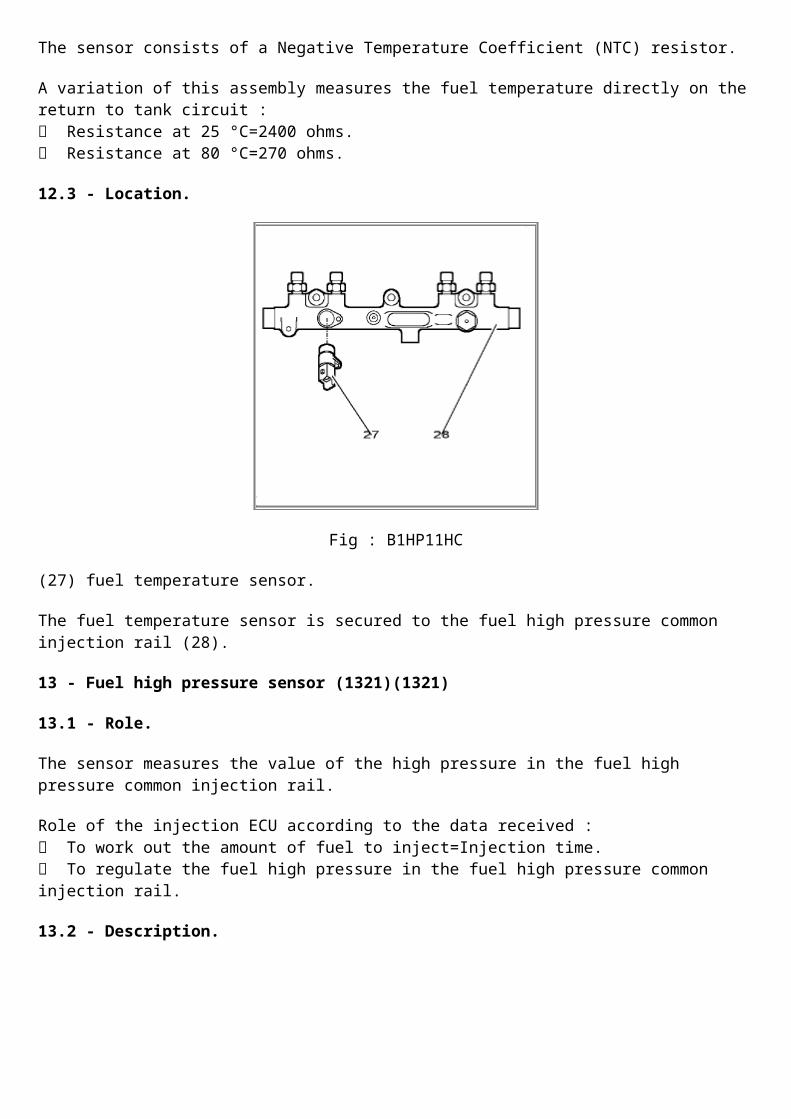
13.2 - Description.
Fig : B1HP11JC
(29) fuel high pressure sensor.
(30) metal seal.
The sensor is of the piezoelectrical type.
The sensor consists of stress gauges.
The sensor provides a voltage which is proportional to the fuel pressure in the high pressure common injection rail.
13.2.1 - Electrical features.
Allocation of the connector channels : Channel 1:Earth. Channel 2:Pressure information (0 to 5 volts). Channel 3:+5 volts supply.
Voltage provided for a pressure of 100 bar:ð 0,5 volt.
Voltage provided for a pressure of 300 bar:ð 1,3 volt.
13.2.2 - Location.
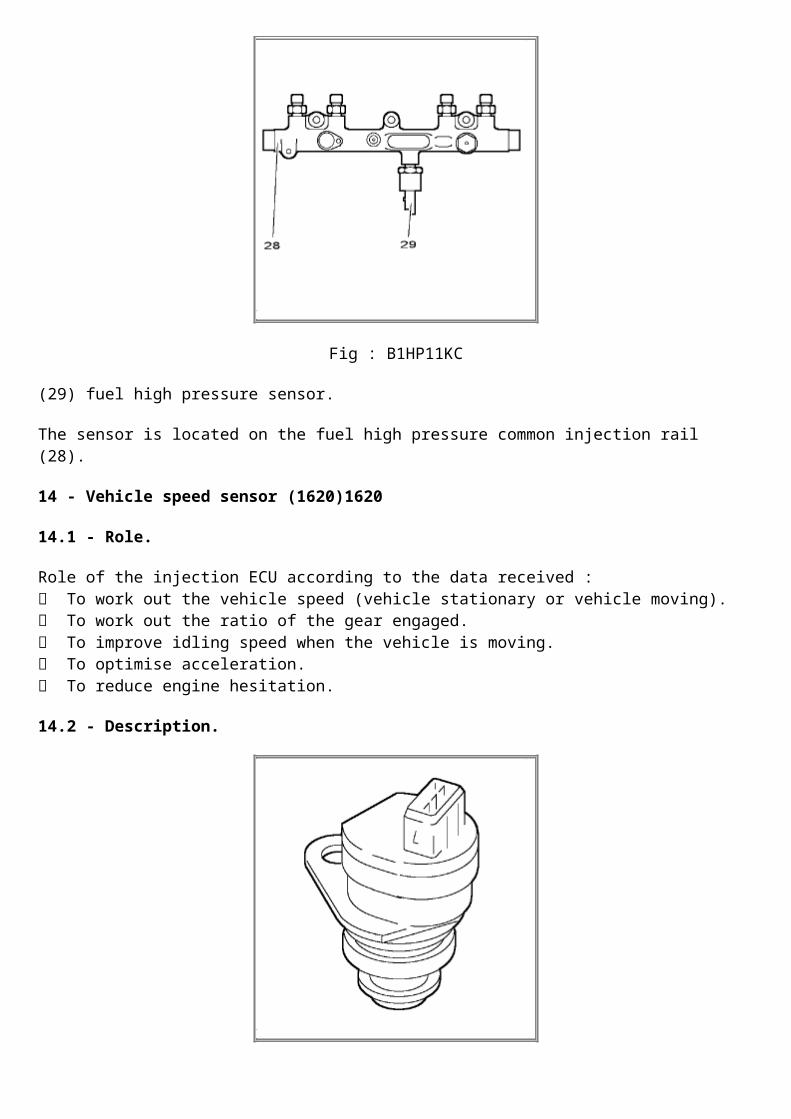
Fig : B1HP11KC
(29) fuel high pressure sensor.
The sensor is located on the fuel high pressure common injection rail (28).
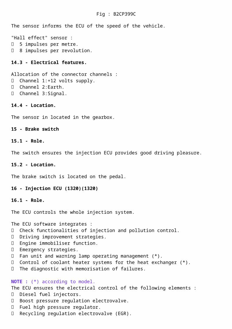
14 - Vehicle speed sensor (1620)1620
14.1 - Role.
Role of the injection ECU according to the data received : To work out the vehicle speed (vehicle stationary or vehicle moving). To work out the ratio of the gear engaged. To improve idling speed when the vehicle is moving. To optimise acceleration. To reduce engine hesitation.
14.2 - Description.
Fig : B2CP399C
The sensor informs the ECU of the speed of the vehicle.
"Hall effect" sensor : 5 impulses per metre. 8 impulses per revolution.
14.3 - Electrical features.
Allocation of the connector channels : Channel 1:+12 volts supply. Channel 2:Earth. Channel 3:Signal.
14.4 - Location.
The sensor in located in the gearbox.
15 - Brake switch
15.1 - Role.
The switch ensures the injection ECU provides good driving pleasure.
15.2 - Location.
The brake switch is located on the pedal.
16 - Injection ECU (1320)(1320)
16.1 - Role.
The ECU controls the whole injection system.
The ECU software integrates : Check functionalities of injection and pollution control. Driving improvement strategies. Engine immobiliser function. Emergency strategies. Fan unit and warning lamp operating management (*). Control of coolant heater systems for the heat exchanger (*). The diagnostic with memorisation of failures.
NOTE : (*) according to model. The ECU ensures the electrical control of the following elements : Diesel fuel injectors. Boost pressure regulation electrovalve. Fuel high pressure regulator. Recycling regulation electrovalve (EGR). Pre and post-heating control unit (post-heating cut-off). Deactivator of the 3rd piston of the high pressure fuel pump.The ECU supplies the following information : Engine speed:To the instrument panel. Consumption at any one time:To the on-board ECU. Air conditioning interruption. Coolant heater operation authorisation (depending on the version).
The atmospheric pressure sensor can not be separated from the injection ECU.
The ECU contains a power stage which can supply the very high control current required for the diesel injectors to operate.
The injection ECU is connected to the injection harness by a 88-way connector.
The injection ECU software is updated by downloading (ECU fitted with a flash EPROM).
16.2 - Allocation of the connector channels.
Channel No. Description
1 +12 volts supply (after double relay)
2 Output:control of injector N° 1
3 Output:control of injector N° 3
4 Output:control of injector N° 4
5 Output:control of injector N° 2
6 Output:control of injector N° 2
7 ---
8Diagnostic line for the coils of the fan unit control relays
9 ---
10 Diagnostic line l
11 Input:air temperature sensor (flowmeter)
12 5 volt output:sensor supply
13 Input:air flow signal (flowmeter)
14 Input:engine speed sensor signal
15 Input:accelerator pedal sensor signal
16 ---
17 ---
18 Input:camshaft sensor signal
19 Input:vehicle speed (vehicle speed sensor)
20 ---
21-22 ---
23Output:engine coolant temperature information (gauge and warning lamp in the instrument panel)
24 ---
25 Output:control of fan unit group 1
26 Output:boost pressure regulation electrovalve
27 Earth:air conditioning pressostat
28 ---
29 +12 volts supply (after double relay)
30 Output:control of injector N° 1
31 Output:control of injector N° 3
32 Output:control of injector N° 4
33 Earth
34 Sensors earth
35 ---
36 Engine immobiliser serial line
37 ---
38 Diagnostic line k
39 Input:fuel temperature sensor
40 Earth
41 Input:engine speed sensor signal
42-43 ---
44 Power supply to sensors (5 volts)
45 Earth:water temperature sensor
46 Input:engine coolant temperature information
47 Input:air conditioning on information (AC/ON)
48 Input:stop lamp switch connection
49 Earth
50 Input:fuel pressure information
51 Earth
52 Output:recycling electrovalve control (EGR)
53 Earth
54-55 ---
56 Output:preheating warning lamp
57 ---
58 Output 1:control of additional heating 1
59-60 ---
61 ---
62 Output:engine speed to instrument panel
63Output:fuel consumption at any moment (trip computer)
64 Input:accelerator pedal sensor
65 ---
66 Input:wake up for injection ECU, wake up for ADC
67 Output:control for preheating unit
68 Input:accelerator pedal sensor
69 After ignition +
70 Input:catalytic converter temperature
71 Input:inlet manifold air pressure
72 ---
73 Input:unused brake switch
74 Input:fuel pressure
75 Air conditioning pressostat (26 bar control stage)
76-79 ---
80Output:deactivator of the 3rd piston of the high pressure fuel pump
81Output:engine coolant temperature information (instrument panel)
The diesel injectors are controlled by 2 control stages of the injection ECU : Control stage 1:Injector group 1 - 4. Control stage 2:Injector group 2 - 3.The control stages of the diesel injectors are used to obtain the following voltages : A peak voltage of 80 volts required when the diesel injectors start to lift. A voltage of 50 volts required to keep the diesel injectors open.
The control stages incorporated into the injection ECU each have a capacitor which stores the power required to control the diesel injectors.
Between each injection, the injection ECU sends pulses on the coil of the injector which is not working.
The pulses create an induced voltage to charge the corresponding control stage (capacitor).
WARNING : The control stage cannot charge itself when a fault is present on the supply line of a diesel injector.
A safety system inside the ECU disconnects the control stages when the engine is switched off.
IMPORTANT : Given the presence of high voltages at the terminals of the ECU and diesel injectors, voltages should always be measured with the recommended equipment.
The diesel injectors inject the amount of fuel required for the engine to operate.
Injecting the fuel directly into the top of the pistons improves engine efficiency.
The fuel can be injected in the following cases : Pre-injection. Main injection. Post-injection.
18.2 - Description.
Fig : B1HP11LD
F:return to fuel tank.
(30) electrical connector.
(31) control electrovalve coil.
(32) control electrovalve spring.
(33) nut.
(34) control electrovalve needle.
(35) diesel injector tip.
(36) diesel injector needle.
(37) pressure chamber.
(38) diesel injector spring.
(39) control piston.
(40) control chamber.
(41) supply nozzle.
(42) fuel return circuit nozzle.
(43) high pressure fuel inlet connector.
(44) laminar filter included in the connector (43).
The control electrovalve is located in the upper part of the diesel injector.
The control electrovalve is secured to the body of the diesel injector by the nut (33).
The diesel injectors have 5 holes which encourage air/fuel mixing.
NOTE : The diameter of the 5 holes of the diesel injectors are suited to the engine version.
IMPORTANT : Do not handle a diesel injector by means of its upper nut (33) (diesel injector will be damaged).
NOTE : The laminar filter requires no maintenance. The amount of fuel injected depends on the following parameters : Duration of the electrical control (injection ECU). Opening speed of the diesel injector. Hydraulic flow of the diesel injector (number and diameter of holes). Fuel pressure in the fuel high pressure common injection rail.
The fuel pressures used in the HDI direct injection system prevent the diesel injectors from being directly electrically controlled.
The diesel injectors open due to the pressure difference between the control chamber (40) and the pressure chamber (37).
The diesel injector needle (36) is held against its seat by the spring (38).
The control piston (36) is fitted on top of the diesel injector needle (39) (the control piston is free within its bore).
The top of the control piston opens out into the control chamber (40).
The control chamber is connected to the following circuits : High pressure fuel circuit through the nozzle (41). Fuel tank return circuit through the nozzle (42).
The control chamber (40) is isolated from the fuel return circuit by the electrovalve needle (34).
The diesel injector needle (36) is held against its seat by the spring (32).
The fuel is distributed evenly between chambers (40) and (37).
Nozzle (42) is larger than nozzle (41).
The electrovalve needle rises as soon as the electrovalve coil is energised (magnetic field).
18.3 - Lifting principle of a diesel injector.
Fig : B1HP11MD
J:diesel injector closed.
K:opening of a diesel injector.
(34) control electrovalve needle.
(36) diesel injector needle.
(37) pressure chamber.
(38) diesel injector spring.
(39) control piston.
(40) control chamber.
(41) supply nozzle.
(42) fuel return circuit nozzle.
18.3.1 - Diesel injector closed.
The force exerted by the high pressure is the same between the control chamber (40) and the pressure chamber (37).
The control piston is locked (held against the diesel injector needle).
The rise in pressure in the fuel high pressure common injection rail encourages the diesel injector to close.
18.3.2 - Opening principle of a diesel injector.
The injection ECU supplies the control electrovalve.
Operating phase as soon as the electrovalve needle (34) lifts up under the action of the control electrovalve (magnetic field) : A fuel leak is created through the nozzle (42). Fuel entering through the nozzle (41) does not compensate for the leak through the nozzle (42). There is no longer a pressure balance between chambers (40) and (37). The pressure in the pressure chamber (37) lifts the diesel injector needle. The control piston lifts up. The fuel is sent to the top of the piston.
NOTE : Fuel injection lasts for as long as the diesel injector electrovalve is energised.
NOTE : Maximum lifting of the control electrovalve needle:ð 0,06 mm.
18.3.3 - Features depending on the time for which the electrovalve is controlled.
Short duration control : The control piston has a certain inertia. The diesel injector needle is lifted slightly. A small amount of fuel is injected. The injection pressure is lower than the pressure in the fuel high pressure injection rail.Long duration control : The control piston and the diesel injector needle have lifted up completely. A large amount of fuel is injected. The injection pressure is equal to the pressure in the high pressure fuel injection rail.
NOTE : The mechanical behaviour of the diesel injector is stored in a cartographic map.
18.3.4 - Closing principle of a diesel injector.
Operating phase as soon as the injection ECU cuts the supply to the diesel injector electrovalve : The electrovalve spring holds the electrovalve needle against its seat. The nozzle (42) is blocked. The fuel leak to the return circuit stops. The rise in pressure in the control chamber (40) causes the diesel injector to close. The pressure balance is restored between chambers (40) and (37). The diesel injector is ready for a new cycle.
18.4 - Control of the diesel injector electrovalves.
Fig : D3AP015C
Diesel injector control current.
Y:amps.
X:duration.
(45) initial current.
(46) holding current.
(47) initial phase.
(48) holding phase.
(49) end of control.
The electrical supply to an electrovalve consists of 2 phases : Initial phase (initial voltage and current). Holding phase (holding voltage and current).
18.4.1 - Initial phase.
The aim of the initial phase is to cause the electrovalve needle to rise rapidly.
The diesel injector electrovalve is supplied as follows : A voltage of approximately 80 volts. A current of approximately 20 A.
NOTE : The initial phase is limited to a few milliseconds (0,3 ms).
18.4.2 - Holding phase.
The holding phase is used to continue the supply to the electrovalve whilst limiting the electrical power absorbed.
The diesel injector electrovalve is supplied as follows : A voltage of approximately 50 volts. A current of approximately 12 A.
18.4.3 - Features of the electrical control.
WARNING : Do not supply a diesel injector with 12 volts (electrovalve is destroyed).
FUNCTION : AIR SUPPLY CIRCUIT
FOR 1CU6 AND B0F7C AND DVY01 AND SINCE O 8276 OR
FOR 2CM4 AND B0F2X AND DVY01 AND SINCE O 8358 OR
FOR 1C6N AND B0F2X AND DVY01 AND SINCE O 8365 OR
FOR 2CU6 AND B0F7C AND DVY01 AND SINCE O 8421 OR
FOR 2CU6 AND B0F7U AND DVY01 AND SINCE O 8421 OR
FOR 1C2X AND B0F7C AND DVY01 AND SINCE O 8001 OR
FOR 1CN6 AND B0F2X AND DVY01 AND SINCE O 8211 TO O 8687 OR
FOR 1CN7 AND B0F2X AND DVY01 AND SINCE O 8688 OR
FOR 1CX4 AND B0F7C AND DVY01 AND SINCE O 8688 OR
FOR 1CX4 AND B0F2X AND DVY01 AND SINCE O 8688
1 - Synopsis
Fig : B1HP10YP
Air circulation (as per arrows) : A:Air. B:Exhaust gas + Air. C:Exhaust gas.
WARNING : The diagram relates to engines with a controlled turbo (injection ECU + electrovalve).
Marked DescriptionPart number in the electrical diagrams
Remarks
1 Injection ECU 1320
2Recycling regulation electrovalve (EGR)
1253
3 Vacuum pump
4 Boost pressure regulation 1233 According to model
Marked DescriptionPart number in the electrical diagrams
Remarks
electrovalve
5Exhaust gas recycling valve (EGR)
6 Air inlet manifold
7 Exhaust gas manifold
8 Boost pressure waste gate Vacuum-controlled
9Pneumatic control capsule for the waste gate (on turbocharger)
Vacuum-controlled
10 Catalytic converter
11 Exhaust turbine
12 Turbocharger
13 Air inlet turbine
14Air flowmeter + air temperature sensor
1310
15 Air filter
16Inlet manifold pressure sensor
1312
17 Air/air heat exchanger According to model
18Atmospheric pressure sensor (integrated in the injection ECU)
1320
NOTE : EGR : exhaust gas recycling device.
2 - Air filter
Replacement intervals:every 60 000 km.
3 - Turbocharger
3.1 - Role.
The turbocharger allows the engine to be turbocharged with air.
There are 2 assembly possibilities : Boost pressure controlled by the injection ECU and the electrovalve. Boost pressure regulated by the waste gate only.
(9) pneumatic control capsule for the waste gate :vacuum-controlled.
(11) exhaust turbine.
(13) air inlet turbine.
(19) pneumatic control capsule for the waste gate :pressure-controlled.
The turbocharger is made of two separate chambers.
The turbocharger consists of the following components : A chamber connected to the engine exhaust function. A chamber connected to the inlet function. A turbine and a compressor, connected by a shaft.
The turbine, activated by the exhaust gas, drives the compressor which compresses the inlet air.
NOTE : Turbocharger lubrication:the very high speeds of the moving parts and temperatures demand a careful lubrication.
The required oil under pressure is taken from the engine oil circuit.
IMPORTANT : Before stopping the engine, it is essential to allow the engine to return to idle.failure to observe this condition may cause the destruction of the turbocharger (lack of lubrication).
The turbocharge pressure is regulated by the waste gate valve.
The boost pressure can be regulated in 2 ways : D assembly:At rest the waste gate is closed. E assembly:At rest the waste gate is open.
3.2.1 - D assembly.
The boost pressure is regulated according to the air pressure in the inlet manifold.
Operating phases once the pressure value of the pneumatic capsule (19) has been exceeded : The boost pressure waste gate opens. The exhaust turbine speed decreases. The boost air pressure decreases.
The decrease in the boost pressure causes the boost pressure waste gate to close.
3.2.2 - E assembly.
The boost pressure is regulated by the electrovalve (4) controlled by the injection ECU (1).
WARNING : The waste gate is open when it is not being pneumatically controlled (vacuum).
The increase in pressure in the inlet manifold is obtained by closing the waste gate.
Operating phases once the injection ECU prevents operation of the electrovalve (4) in order to limit the boost pressure : The vacuum pump no longer communicates with the pneumatic control capsule (9). The boost pressure waste gate opens. The exhaust turbine speed decreases. The boost air pressure decreases.
4 - Atmospheric pressure sensor (1320)1320
4.1 - Role.
The sensor measures the atmospheric pressure.
Role of the injection ECU according to the data received : To determine the air density. To prevent recycling when driving at high altitude.
NOTE : Air density decreases as altitude increases.
4.2 - Description.
The sensor is of the piezoelectrical type.
The sensor consists of stress gauges.
The sensor supplies a voltage proportional to the atmospheric pressure.
4.3 - Location.
Fig : B1HP110C
The atmospheric pressure sensor (18) is integrated in the injection ECU.
WARNING : The atmospheric pressure sensor can not be separated from the injection ECU.
5 - Air/air heat exchanger
5.1 - Role.
The air/air heat exchanger cools the air entering the cylinders in order to increase the air density within the cylinders.
Due to the increase of the air density, the motor's performances increase.
5.2 - Location.
Location:on the front panel of the vehicle.
6 - Inlet manifold pressure sensor (1312)1312
6.1 - Role.
The sensor enables to determinate the air pressure in the intake pipe.
Role of the injection ECU according to the data received : Regulate the boost pressure (*). Regulate the HP fuel pressure.
The sensor is connected to the inlet air circuit at the air/air heat exchanger.
The sensor is of the piezoelectrical type.
The sensor consists of stress gauges.
The pressure sensor supplies a voltage proportional to the air pressure in the inlet manifold.
6.3 - Electrical features.
Allocation of the connector channels : Channel 1:5 volts. Channel 2:Earth. Channel 3:Signal.
Pressure of 1,3 bar=output voltage of 1 volt.
7 - Vacuum pump
7.1 - Role.
The vacuum pump supplies the vacuum required to control the following components : Exhaust gas recycling valve (EGR) (depending on the version). Pneumatic control capsule for the EGR valve. Brake servo (depending on the version).
7.2 - Description.
The vane-type vacuum pump is driven by the engine camshaft.
Fig : B1HP112C
(3) vacuum pump.
(20) safety valve (the valve is integrated in the outlet union).
A safety valve integrated in the pump isolates the brake vacuum circuit with the engine switched off.
The safety valve allows the following to be retained : A vacuum reserve in the brake servo. Braking assistance for several applications of the brake.
7.3 - Location.
Location:on the cylinder head at the end of the camshaft, gearbox side.
Vehicle application:vehicles with boost pressure controlled by the injection ECU.
8.1 - Role.
The regulating electrovalve controls the boost pressure waste gate.
Role of the boost pressure regulating electrovalve : Regulate the boost pressure. To limit the boost pressure.
Regulation of the boost pressure is progressive and is controlled by mapping (injection ECU).
8.2 - Description.
Fig : B1HP113C
(21) electrical connector.
D:"user" outlet.
E:pressure drop inlet for the vacuum pump.
F:white marking.
G:atmospheric pressure inlet.
The electrovalve control is of the OCR type (open cycle ratio).
The proportional electrovalve controlled by an OCR voltage is connected to the following components : Atmospheric pressure. Vacuum supplied by the vacuum pump.
The pressure supplied by the electrovalve is included between the atmospheric pressure and the vacuum pump vacuum.
8.3 - Electrical features.
Control:injection ECU (earth).
Variable voltage control (OCR) : Full supply (maximum OCR)=Maximum vacuum. No supply (minimum OCR)=No vacuum (atmospheric pressure).
NOTE : OCR : Open Cycle Ratio.
8.4 - Location.
Fig : B1HP114C
(4) boost pressure regulation electrovalve.
The electrovalve is located in the engine compartment.
FUNCTION : RECYCLING OF EXHAUST GASES
FOR 1C2X AND B0F7C AND DVY01 AND SINCE O 8001 OR
FOR 1CN6 AND B0F2X AND DVY01 AND SINCE O 8211 TO O 8687 OR
FOR 1CN7 AND B0F2X AND DVY01 AND SINCE O 8688 OR
FOR 1CX4 AND B0F2X AND DVY01 AND SINCE O 8688 OR
FOR 1CX4 AND B0F7C AND DVY01 AND SINCE O 8688 OR
FOR 1CU6 AND B0F7C AND DVY01 AND SINCE O 8276 OR
FOR 2CM4 AND B0F2X AND DVY01 AND SINCE O 8358 OR
FOR 1C6N AND B0F2X AND DVY01 AND SINCE O 8365 OR
FOR 2CU6 AND B0F7C AND DVY01 AND SINCE O 8421 OR
FOR 2CU6 AND B0F7U AND DVY01 AND SINCE O 8421
1 - Synopsis
Fig : B1HP10YP
Air circulation (as per arrows) : A:Air. B:Exhaust gas + Air. C:Exhaust gas.
WARNING : The diagram relates to engines with a controlled turbo (injection ECU + electrovalve).
Marked DescriptionPart number in the electrical diagrams
Remarks
1 Injection ECU 1320
2Recycling regulation electrovalve (EGR)
1253
3 Vacuum pump
4Boost pressure regulation electrovalve
1233 According to model
5Exhaust gas recycling valve (EGR)
6 Air inlet manifold
7 Exhaust gas manifold
8 Boost pressure waste gate Vacuum-controlled
9Pneumatic control capsule for the waste gate (on turbocharger)
Vacuum-controlled
10 Catalytic converter
11 Exhaust turbine
12 Turbocharger
13 Air inlet turbine
14Air flowmeter + air temperature sensor
1310
15 Air filter
16Inlet manifold pressure sensor
1312
17 Air/air heat exchanger According to model
18Atmospheric pressure sensor (integrated in the injection ECU)
1320
NOTE : EGR : exhaust gas recycling device.
2 - Air flowmeter (1310)(1310)
2.1 - Role.
The air flowmeter measures the flow of fresh air taken in by the engine.
Role of the injection ECU according to the data received : To calculate the exhaust gas recycling rate. To limit smoke production during the transitional phases (acceleration, deceleration) by correcting the fuel flow.
2.2 - Description.
Fig : B1HP115D
(19) electrical connector.
(20) protective grille.
(21) metallic plate (hot film).
(22) air temperature sensor.
The air flowmeter consists of the following components : Metallic plate (hot film). Air temperature sensor.
The metallic plate is very thin and allows the amount of air entering the air circuit to be calculated.
The metallic plate consists of the following components : Heating resistor. Measurement resistor (NTC).
The injection ECU supplies the heating resistor in order to keep the metallic plate at a fixed temperature.
The air passing through the flowmeter cools the metallic plate:the measurement resistor (NTC) varies.
The ECU relates the measurement resistor value to the air flow.
IMPORTANT : Do not touch the metallic plate; the use of an air nozzle is forbidden.
2.3 - Electrical features.
Allocation of the connector channels : Channel 1:Air temperature information. Channel 2:+12 volts supply. Channel 3:Earth. Channel 4:Line unused. Channel 5:Air flow data. Channel 6:Earth.
2.4 - Location.
The air flow meter is located between the air filter and the turbocharger.
3 - Vacuum pump
The vacuum pump supplies the vacuum required to control the following components : Exhaust gas recycling valve (EGR) (depending on the version). Pneumatic control capsule for the EGR valve. Brake servo (depending on the version).
Vehicle application:vehicles with boost pressure controlled by the injection ECU.
4.1 - Role.
The regulating electrovalve controls the boost pressure waste gate.
Role of the boost pressure regulating electrovalve : Regulate the boost pressure. To limit the boost pressure.
Regulation of the boost pressure is progressive and is controlled by mapping (injection ECU).
4.2 - Description.
The electrovalve links the vacuum pump and the exhaust gas recycling valve capsule.
Fig : B1HP116C
(23) electrical connector.
A:"user" outlet.
B:pressure drop inlet for the vacuum pump.
C:white marking.
D:atmospheric pressure inlet.
The electrovalve control is of the OCR type (open cycle ratio).
The proportional electrovalve controlled by an OCR voltage is connected to the following components : Atmospheric pressure. Vacuum supplied by the vacuum pump.
The pressure supplied by the electrovalve is included between the atmospheric pressure and the vacuum pump vacuum.
4.3 - Electrical features.
Control:injection ECU (earth).
Variable voltage control (OCR) : Full supply (maximum OCR)=Maximum vacuum. No supply (minimum OCR)=No vacuum (atmospheric pressure). Resistance at 25 °C=5 ohms.
NOTE : OCR : Open Cycle Ratio.
4.4 - Location.
Fig : B1HP117C
(2) boost pressure regulation electrovalve.
The electrovalve is located in the engine compartment.
5 - Exhaust gas recycling valve (EGR)
5.1 - Role.
The exhaust gas recycling valve checks the amount of exhaust gas that is recycled.
The exhaust gas recycling (EGR) device reduces the amount of nitrogen oxide (NOx) emitted by the exhaust.
The reduction of the nitrogen oxide is achieved by re-injecting part of the exhaust gas into the cylinders.
The recycling phases are memorized in injection ECU mapping.
WARNING : The gas recycling valve is shut when it is not being pneumatically controlled (vacuum). Operating phases when the pneumatic control capsule is supplied with a vacuum : The gas recycling valve opens. Part of the exhaust gas is absorbed by the engine (air inlet manifold).
5.3 - Location.
The recycling valve is mounted on the exhaust manifold.
6 - Catalytic converter
The catalytic converter is a 2-way type catalytic converter.
The catalytic converter (located on the exhaust line) enables the reduction of output into the atmosphere of the following components : Carbon monoxide (CO). Non-burned hydrocarbons (HC).
Post-injection combined with a nitrogen oxide catalytic converter can reduce the quantity of nitrogen oxide as well as other pollutants (4-way catalytic converter).
FUNCTION : PRE-POST HEATING
FOR 1C2X AND B0F7C AND DVY01 AND SINCE O 8001 OR
FOR 1CN6 AND B0F2X AND DVY01 AND SINCE O 8211 TO O 8687 OR
FOR 1CN7 AND B0F2X AND DVY01 AND SINCE O 8688 OR
FOR 1CX4 AND B0F2X AND DVY01 AND SINCE O 8688 OR
FOR 1CX4 AND B0F7C AND DVY01 AND SINCE O 8688 OR
FOR 1CU6 AND B0F7C AND DVY01 AND SINCE O 8276 OR
FOR 2CM4 AND B0F2X AND DVY01 AND SINCE O 8358 OR
FOR 1C6N AND B0F2X AND DVY01 AND SINCE O 8365 OR
FOR 2CU6 AND B0F7C AND DVY01 AND SINCE O 8421 OR
FOR 2CU6 AND B0F7U AND DVY01 AND SINCE O 8421
1 - Synopsis
Fig : D3AP016C
(1150) pre-post heating control unit.
(1160) preheater plugs.
(1320) engine management ECU.
(V1150) preheating warning lamp.
2 - Preheater plugs (1160)(1160)
2.1 - Role.
The preheater plugs allow a rapid increase in the temperature in the combustion chambers during starting.
2.2 - Description.
Fig : B1HP11PC
11 volt preheater plugs.
Total length of 107 mm.
Composition of the preheater plugs : A heating resistor. A metallic protective cover.
3 - Pre-post heating control unit (1150)(1150)
3.1 - Role.
The housing supplies the preheating plugs with electricity following the injection ECU's commands.
3.2 - Description.
The pre and post-heating times are determined by the injection ECU.
If the preheater control unit develops a fault, the injection ECU will memorise the fault.
3.3 - Electrical features.
Allocation of the connector channels : Line N° 1:Earth. Line N° 2:Line unused. Line N° 3:After ignition +12 volts. Line N° 4:Engine check ECU input. Line N° 5:Preheater control unit diagnostic. Line N° 8:Permanent +12 volts. Line N° 9:Supply to the preheater plugs.
3.4 - Location.
According to vehicle.
FUNCTION : ENGINE COOLING (INTEGRATED IN THE INJECTION ECU)
FOR 1C2X AND B0F7C AND DVY01 AND SINCE O 8001 OR
FOR 1CN6 AND B0F2X AND DVY01 AND SINCE O 8211 TO O 8687 OR
FOR 1CN7 AND B0F2X AND DVY01 AND SINCE O 8688 OR
FOR 1CX4 AND B0F2X AND DVY01 AND SINCE O 8688 OR
FOR 1CX4 AND B0F7C AND DVY01 AND SINCE O 8688 OR
FOR 1CU6 AND B0F7C AND DVY01 AND SINCE O 8276 OR
FOR 2CM4 AND B0F2X AND DVY01 AND SINCE O 8358 OR
FOR 1C6N AND B0F2X AND DVY01 AND SINCE O 8365 OR
FOR 2CU6 AND B0F7C AND DVY01 AND SINCE O 8421 OR
FOR 2CU6 AND B0F7U AND DVY01 AND SINCE O 8421
Functions of the injection ECU : To control the cutting in and cutting out of the cooling fan(s) (engine cooling and air conditioning function). To check the post-cooling (for a maximum of 6 minutes). To control the lighting of the coolant temperature warning lamp in the control panel (*). To control the coolant temperature gauge in the control panel (*). To carry out a diagnostic check of the operation of the cooling fan(s). To establish the engine coolant temperature. To manage the back-up modes.
NOTE : (*) according to model.
1 - Synopsis
Fig : D3AP017D
A:assembly with 2 cooling fans.
B:assembly with 1 cooling fan.
+BAT=battery +.
+ACC=+ accessories.
(1) double injection relay.
(2) dashboard instrument cluster (gauge and warning lamp in the instrument panel).
(3) relay 1.
(4) cooling fan 1.
(5) relay 2.
(6) relay 3.
(7) cooling fan 2.
(8) engine coolant temperature sensor.
(9) injection ECU.
(10) air conditioning compressor control.
(11) air conditioning activated information.
(12) resistor.
2 - Engine coolant temperature sensor (1220)(1220)
The engine coolant temperature sensor informs the ECU about the engine coolant temperature.
The sensor consists of a Negative Temperature Coefficient (NTC) resistor.
The more the temperature increases, the more its resistance value is reduced.
The water temperature sensor is fitted to the coolant unit.
WARNING : There are 2 types of coolant temperature sensor assembly.
3 - Air conditioning activated information
This information is provided by the air conditioning ECU when the air conditioning is activated.
The cooling fan(s) is(are) operated at low speed when the air conditioning activated information is received by the injection ECU.
4 - Electric cooling fan unit
There are 2 assembly possibilities : Assembly with 1 cooling fan. Assembly with 2 cooling fans.
WARNING : The cooling fan(s) cut-in and cut-out thresholds depend on the vehicle:refer to the relevant documentation.
4.1 - Assembly with 1 cooling fan.
There are 2 operating speeds : Slow speed. Fast speed.
Slow speed is obtained by supplying the cooling fan via a resistor arranged in series in the supply circuit.
Fast speed is obtained by supplying the cooling fan directly.
The change from slow to fast speed takes place immediately.
Before changing to fast speed, the cooling fan(s) is(are) run for 3 seconds at slow speed.
4.2 - Assembly with 2 cooling fans.
There are 2 operating speeds : Slow speed. Fast speed.
Slow speed is obtained by supplying the cooling fans in series.
Fast speed is obtained by supplying the cooling fans in parallel.
The change from slow to fast speed takes place immediately.
Before changing to fast speed, the cooling fan(s) is(are) run for 3 seconds at slow speed.
5 - Post-cooling
When the engine stops, the ECU will operate the post-cooling if the coolant temperature exceeds a certain threshold (*).
Post-cooling occurs at slow speed and lasts for a maximum of 6 minutes after the engine has stopped.
NOTE : Post-cooling can not occur if the battery voltage is less than 10,5 volts when the ignition is switched off.
(*) according to vehicle.
6 - Back-up mode
Role of the injection ECU if the coolant temperature sensor is faulty : To operate the cooling fan(s) at fast speed. To activate the coolant temperature warning lamp in the control panel so that it flashes (depending on the version).