196
ENGLISH HDS Gen3 Operator Manual www.lowrance.com

ENGLISH
HDS Gen3Operator Manual
www.lowrance.com


Preface
DisclaimerAs Navico is continuously improving this product, we retain theright to make changes to the product at any time which may not bereflected in this version of the manual. Please contact your nearestdistributor if you require any further assistance.
It is the owner’s sole responsibility to install and use the equipmentin a manner that will not cause accidents, personal injury orproperty damage. The user of this product is solely responsible forobserving safe boating practices.
NAVICO HOLDING AS AND ITS SUBSIDIARIES, BRANCHES ANDAFFILIATES DISCLAIM ALL LIABILITY FOR ANY USE OF THIS PRODUCTIN A WAY THAT MAY CAUSE ACCIDENTS, DAMAGE OR THAT MAYVIOLATE THE LAW.
Governing Language: This statement, any instruction manuals, userguides and other information relating to the product(Documentation) may be translated to, or has been translated from,another language (Translation). In the event of any conflict betweenany Translation of the Documentation, the English language versionof the Documentation will be the official version of theDocumentation.
This manual represents the product as at the time of printing.Navico Holding AS and its subsidiaries, branches and affiliatesreserve the right to make changes to specifications without notice.
TrademarksLowrance® and Navico® are registered trademarks of Navico.
Navionics® is a registered trademark of Navionics, Inc.
NMEA® and NMEA 2000® are registered trademarks of the NationalMarine Electronics Association.
SiriusXM® is a registered trademark of Sirius XM Radio Inc.
Fishing Hot Spots® is a registered trademark of Fishing Hot Spots Inc.Copyright© 2012 Fishing Hot Spots.
FUSION-Link™ Marine Entertainment Standard™ is a registeredtrademark of FUSION Electronics Ltd.
C-MAP® is a registered trademark of C-MAP.
FLIR® is a registered trademark of FLIR.
Preface | HDS Gen3 Operator Manual 3

Mercury® is a registered trademark of Mercury.
SmartCraft VesselView® is a registered trademark of Mercury.
Suzuki® is a registered trademark of Suzuki.
SD™ and microSD™ are trademarks or registered trademarks ofSD-3C, LLC in the United States, other countries or both.
Wi-Fi® is a registered trademark of the Wi-Fi Alliance®.
Additional mapping data: Copyright© 2012 NSI, Inc.: Copyright©2012 by Richardson’s Maptech.
Bluetooth® is a registered trademark of Bluetooth SIG, Inc.
Power-Pole® is a registered trademark of JL Marine Systems, Inc.
C-Monster™ is a trademark of JL Marine Systems, Inc.
Navico product referencesThis manual can refer to the following Navico products:
• Broadband Radar™ (Broadband Radar)• Broadband 3G™ Radar (Broadband 3G Radar)• Broadband 4G™ Radar (Broadband 4G Radar)• Broadband Sounder™ (Broadband Sounder)• DownScan Imaging™ (DownScan)• DownScan Overlay™ (Overlay)• GoFree™ (GoFree)• INSIGHT GENESIS® (Insight Genesis)• SmartSteer™ (SmartSteer)• SonicHub® (SonicHub)• StructureMap™ (StructureMap)• StructureScan® (StructureScan)• StructureScan® HD (StructureScan HD)
CopyrightCopyright © 2017 Navico Holding AS.
WarrantyThe warranty card is supplied as a separate document.
In case of any queries, refer to the brand website of your display orsystem: www.lowrance.com.
4 Preface | HDS Gen3 Operator Manual

Compliance statementsThis equipment complies with:
• CE under 2014/53/EU Directive• The requirements of level 2 devices of the Radio communications
(Electromagnetic Compatibility) standard 2008• Part 15 of the FCC Rules. Operation is subject to the following
two conditions: (1) this device may not cause harmfulinterference, and (2) this device must accept any interferencereceived, including interference that may cause undesiredoperation.
The relevant Declaration of conformity is available in the product'ssection at the following website: www.lowrance.com.
Internet usageSome features in this product use an internet connection toperform data downloads and uploads. Internet usage via aconnected mobile/cell phone internet connection or a pay-per-MBtype internet connection may require large data usage. Your serviceprovider may charge you based on the amount of data you transfer.If you are unsure, contact your service provider to confirm rates andrestrictions.
About this manualThis manual is a reference guide for operating the HDS Gen3. Itassumes that all equipment is installed and configured, and that thesystem is ready to use.
The manual assumes that the user has basic knowledge ofnavigation, nautical terminology and practices.
Important text that requires special attention from the reader isemphasized as follows:
Ú Note: Used to draw the reader’s attention to a comment orsome important information.
Preface | HDS Gen3 Operator Manual 5

Warning: Used when it is necessary to warnpersonnel that they should proceed carefully toprevent risk of injury and/or damage to equipment/personnel.
Manual versionThis manual is written for software version 4.5. The manual iscontinually updated to match new software releases. The latestavailable manual version can be downloaded fromwww.lowrance.com.
Viewing the manual on the screenThe PDF viewer included in the unit makes it possible to read themanuals and other PDF files on the screen. Manuals can bedownloaded from www.lowrance.com.
The manuals can be read from a card inserted in the card reader orcopied to the unit’s internal memory.
Use the menu options or the keys and on-screen buttons tomaneuver in the PDF file as described below:
• Search, Goto page, Page Up and Down
6 Preface | HDS Gen3 Operator Manual

Select the relevant panel button.• Scroll pages
Touch operation: Drag finger on the screen in any direction.Key operation: Use the Cursor keys.
• Panning on the pageTouch operation: Drag finger on the screen in any direction.Key operation: Use the arrow keys.
• Zoom In/OutSelect the relevant panel button.Touch operation: Use pinch or spread gestures.Key operation: Use the + and - keys.
• Exit the PDF viewerTouch operation: Select the X in the upper right corner of thepanel.Key operation: Press the X key.
The Software versionThe software version currently on this unit can be found in theAbout dialog. The About dialog is available in the System Settings.For more information, refer to "About" on page 171. For upgradingyour software, refer to "Software upgrades" on page 179.
Preface | HDS Gen3 Operator Manual 7

8 Preface | HDS Gen3 Operator Manual

Contents
15 Introduction15 Operating the system16 The front panel and keys18 The Home page19 Application pages21 Integration of 3rd party devices
25 Basic operation25 System Controls dialog25 Turning the system on and off26 Display illumination26 Locking the touchscreen26 Using menus and dialogs27 Selecting pages and panels28 Using the cursor on the panel29 Creating a Man Overboard waypoint30 Screen capture
31 Customizing your system31 Customizing the Home page wallpaper31 Adjusting panel size32 Data Overlay32 Adding new favorite pages33 Edit favorite pages
34 Charts34 The Chart panel35 Chart data35 Showing dual chart types36 Panning the chart36 Vessel symbol36 Chart scale37 Positioning the vessel on the chart panel37 Displaying information about chart items38 Using the cursor on the chart panel38 Creating routes39 Find objects on chart panels39 3D charts
Contents | HDS Gen3 Operator Manual 9

40 Chart overlay40 Insight and C-MAP charts45 Navionics charts51 Chart settings
54 Waypoints, Routes, and Trails54 Waypoints, Routes, and Trails dialogs54 Waypoints57 Routes61 Trails
63 Navigating63 Steer panel64 Navigate to cursor position64 Navigate a route65 Navigating with the autopilot66 Navigation settings
68 Sonar68 The Sonar image69 Multiple Sonar69 Zooming the image69 Using the cursor on the image69 Viewing history70 Setting up the image72 Stop sonar72 Advanced options73 Start recording log data74 Stop recording log data75 Viewing the recorded sounder data76 Sonar view options78 Sonar settings
82 StructureScan82 The StructureScan image83 Zooming the StructureScan image83 Using the cursor on the StructureScan panel84 Viewing StructureScan history85 Setting up the StructureScan image86 Stop sonar
10 Contents | HDS Gen3 Operator Manual

86 Advanced StructureScan settings
88 SpotlightScan88 The SpotlightScan image89 SpotlightScan setup90 SpotlightScan options91 SpotlightScan operation tips
93 StructureMap93 The StructureMap image93 Activating Structure overlay94 StructureMap sources95 StructureMap tips95 Recording StructureScan data96 Using StructureMap with mapping cards97 Structure options
99 Info panels99 Dashboards99 Customizing the Info panel
101 Video101 The Video panel101 Setting up the video panel
102 Simulator102 Demo mode102 Simulator source files103 Advanced simulator settings
104 Trolling motor autopilot104 Safe operation with the autopilot104 Switching from automatic navigation to standby mode105 Autopilot interface106 Autopilot control of the trolling motor109 Autopilot settings
112 Outboard motor autopilot112 Safe operation with the autopilot
Contents | HDS Gen3 Operator Manual 11

112 Autopilot control of the outboard motor(s)112 Mode overview121 Autopilot settings
123 Wireless connection123 Connect and disconnect from a wireless hotspot124 GoFree Shop124 GoFree Link126 Uploading log files to Insight Genesis126 Bluetooth wireless technology127 Wireless settings
130 Radar130 The Radar panel131 Radar overlay131 Radar operational modes132 Radar Range132 Using the cursor on a radar panel132 Adjusting the radar image133 Advanced radar options135 Radar view options137 EBL/VRM markers138 Setting a guard zone around your vessel139 MARPA targets141 Recording radar data142 Radar settings
144 AIS144 AIS target symbols145 Searching for AIS items145 Viewing information about single AIS targets146 AIS information on radar panels146 Calling an AIS vessel147 AIS SART148 Vessel alarms149 Vessel settings
152 Audio152 Enabling audio153 SonicHub 2
12 Contents | HDS Gen3 Operator Manual

156 The Media bar157 Setting up the audio system157 Audio controls157 Device explorer158 Audio options158 Audio mixer159 Auxiliary sources159 Radio161 DVD video
162 SiriusXM weather162 Sirius status panel162 Sirius weather display164 Sirius view options165 Weather icons166 Local weather166 Marine zones167 Tropical statements167 Adjusting color codes167 Animating Sirius weather graphics167 Weather alarms
169 Tools169 Waypoints/routes/trails169 Tides169 Alarms169 Settings173 Vessels173 Sun, Moon173 Trip calculator173 Files173 Find174 GoFree Shop
175 Alarms175 Alarm system175 Type of messages175 Single alarms175 Multiple alarms176 Acknowledging a message
Contents | HDS Gen3 Operator Manual 13

176 Alarms dialog
178 Maintenance178 Preventive maintenance178 Checking the connectors178 Touchscreen calibration178 NMEA Data logging179 Software upgrades181 Backing up your system data
184 Touchscreen operation
14 Contents | HDS Gen3 Operator Manual

Introduction
Operating the systemYou can use both the keys and the touchscreen to operate the HDSGen3.
This manual uses the following general terminology to describeoperating the unit:
Select• Touch: Tap the panel
• Key: Use the cursor keys to select, then confirm by pressing theEnter key
Press and hold• Touch: Press and hold on the screen• Key: Use the cursor keys to select, then press and hold the Enter
key
Drag• Touch: Drag an item to a new position• Key: Use the cursor keys to select an item, confirm by pressing
the Enter key. Use the cursor keys to select a new position, andthen press the Enter key again to confirm the new position.
1
Introduction | HDS Gen3 Operator Manual 15

The front panel and keys
11
5
2
4
76
89
101
3
12
1 Touchscreen
2 Pages keyPress once to activate the Home page. Repeat shortpresses to cycle the favorite buttons. Press and hold froman active page to go to the last used page.
3 Cursor keysPress arrows to move through menu items, to adjust avalue, and to move the cursor on a panel.
4 Zoom Out / Zoom In keys and MOB keyZoom keys for panels and images. Simultaneous pressingboth keys saves a Man Overboard (MOB) waypoint at thecurrent vessel position.
5 Exit (X) keyPress to exit a dialog, to return to previous menu level, andto remove the cursor from the panel.
6 Menu keyA single press displays the menu for the active panel/overlay. Press and hold to hide or show the menu. A quickdouble-press displays the settings menu.
16 Introduction | HDS Gen3 Operator Manual

7 Waypoint keyPress to display the dialog for saving new waypoints. Presstwice to quick save a waypoint. Press and hold to access theFind menu.
8 Enter keyPress to select or save your settings.
9 Panel keyUsed on multiple-panel pages. A short press switchesbetween the panels, a long press expands active panel to afull page panel and back again.
10 Power keyPress once to display the System Controls dialog. Repeatshort presses to cycle the backlight brightness. Press andhold to turn the unit ON/OFF.
11 Card reader door
12 microSD Card readers
Introduction | HDS Gen3 Operator Manual 17

The Home pageThe Home page is accessed from any operation by a short press onthe Pages key.
1 ToolsSelect a button to access dialogs used for carrying out atask, or for browsing stored information.
2 Local time and Water depth
3 ApplicationsSelect a button to display the application as a full pagepanel.Press and hold a button to display pre-configured splitpage options for the application.
4 Close buttonSelect to exit the Home page and return to the previousactive page.
5 FavoritesSelect a button to display the panel combination.Press and hold a favorite button to enter edit mode for theFavorites panel.
18 Introduction | HDS Gen3 Operator Manual

Application pages
Each application connected to the system is presented on panels.The application can be presented as a full page, or in combinationwith other panels in a multiple panel page.
All application pages are accessed from the Home page.
1 Application panel
2 MenuPanel specific menu.
3 System Controls dialogQuick access to basic system settings. Display the dialog bya short press on the Power key.
4 DialogInformation to or input from the user.
5 Alarm messageDisplayed if dangerous situations or system faults occur.
Split pagesYou can have up to 4 panels on each page.
Introduction | HDS Gen3 Operator Manual 19

2 panels page 3 panels page 4 panels page
Panel sizes in a split page can be adjusted from the SystemControls dialog.
Quick split pagesEach full screen application has several pre-configured quick splitpages, featuring the selected application combined with each ofthe other panels.
Ú Note: The number of quick split pages cannot be changed, andthe pages cannot be customized or deleted.
Access a quick split page by pressing and holding the applicationbutton on the Home page.
Favorite pages All preconfigured favorite pages can be modified and deleted, andyou can create your own. You can have a total of 12 favorite pages.
For more information, refer to "Adding new favorite pages" on page 32.
20 Introduction | HDS Gen3 Operator Manual

Integration of 3rd party devicesSeveral 3rd party devices can be connected to the HDS Gen3. Theapplications are displayed on separate panels or integrated withother panels.
A device connected to the NMEA 2000 network shouldautomatically be identified by the system. If not, enable the featurefrom the advanced option in the System settings dialog.
The 3rd party device is operated by using menus and dialogs as onother panels.
This manual does not include specific operation instructions for any3rd party device. For features and functionality, refer to thedocumentation included with the 3rd party device.
SmartCraft VesselView integrationSmartCraft data can be displayed and interaction are enabledthrough the unit when a Mercury VesselView® 4, 7, 403, 502, 702,703, or Link is present on the network.
When the features are enabled, the display may prompt the user forsome basic configuration information. Refer to the VesselView®manual or engine supplier for further information.
The engine supplier icon appears on the Home page when adevice is available.
Suzuki Engine panelIf a Suzuki C10 gauge is available on the network, a Suzuki engineicon is added to the Home page. An icon is also added to the Pageeditor. You can select to display the Suzuki engine panel as a fullpage panel or as part of a multi-panel page.
The layout and content of the engine panel depends on selectedpanel size. The digital gauges can be customized, refer to "Customizingthe panel" on page 99.
FUSION-Link integrationFUSION-Link devices connected to the NMEA 2000 network can becontrolled from the HDS Gen3 system.
The FUSION-Link devices appear as additional sources when usingthe audio function. No additional icons are available.
Introduction | HDS Gen3 Operator Manual 21

Refer to "Audio" on page 152 for more information.
BEP CZone integrationThe HDS Gen3 integrates with BEP’s CZone system used forcontrolling and monitoring a distributed power system on yourvessel.
The CZone icon is available in the Tools panel on the Home pagewhen a CZone system is available on the network.
A separate manual is provided with your CZone system. Refer to thisdocumentation and to the HDS Gen3 Installation manual for how toinstall and configure the CZone system.
CZone dashboardWhen the CZone is installed and configured, an additional CZonedashboard is added to the Info panels.
You switch between a panel’s dashboards by selecting the left andright arrow symbols or by selecting the dashboard from the menu.
Editing a CZone dashboardYou can customize a CZone dashboard by changing the data foreach of the gauges. Available editing options depend on the type ofgauge and which data sources that are connected to your system.
For more information, refer to "Info panels" on page 99.
Power-Pole anchorsPower-Pole anchors, which can be controlled by the C-MonsterControl System installed on your boat, can be controlled from theHDS Gen3. To control the Power-Poles, you pair the Power-Poleswith the HDS Gen3 using Bluetooth wireless technology available inboth products.
Power-Pole controlsWhen Power-Poles are paired with the HDS Gen3, the Power-Polebutton becomes available in the System Controls dialog. Select it todisplay the Power-Pole controller.
For pairing Bluetooth devices, refer to "Pairing Bluetooth devices" on page126. If you are pairing dual Power-Poles, also review "Pairing with dualPower-Poles" on page 127.
22 Introduction | HDS Gen3 Operator Manual

When the Power-Pole controller is opened, the system connects topaired Power-Poles. When the connection is confirmed the controlbuttons are enabled.
Ú Note: The controls are grayed out until the system connectswith the Power-Poles. Once connected and functional thearrows in the dialog turn white.
The Power-Pole controller displays control buttons for each Power-Pole that is paired to the HDS Gen3.
Single press the Auto buttons to raise and lower the Power-Polesautomatically all the way up and down. The manual up and downbuttons raise and lower them as quickly, and as high or low as youwant.
Single Power-Pole controllerDual Power-Poles controller
On a dual controller you can raise and lower the Power-Polesseparately, or press the sync (links) button to allow for control ofboth with a single press of the auto buttons or the manual up anddown buttons.
Stay connectedSelect the Stay connected (cog) button on the Power-Polecontroller to open the Power-Pole settings dialog where you canselect to stay connected to all paired Power-Pole anchors.
Ú Note: Selecting to Stay connected speeds up access to thecontrols, but the anchors cannot be controlled from anotherdisplay when it is selected. Turn off this option to allowconnection from other displays.
Introduction | HDS Gen3 Operator Manual 23

24 Introduction | HDS Gen3 Operator Manual

Basic operation
System Controls dialogThe System Controls dialog provides quick access to basic systemsettings. You display the dialog by making a short press on thePower key.
The icons displayed on the dialog can vary. For example, the adjustsplits option is only available if you are viewing a split page whenyou open the System Controls dialog.
Activating functionsSelect the icon of the function you want to set or toggle on or off.For those functions that toggle on and off, an orange bar across thetop of the icon indicates the function is activated, as shown in theData Overlay icon above.
Turning the system on and offYou turn the system on and off by pressing and holding the Powerkey. You can also turn the unit off from the System Controlsdialog.
If the Power key is released before the shut-down is completed, thepower off process is cancelled.
Standby modeIn Standby mode, the Sonar and the backlight for screen and keysare turned off to save power. The system continues to run in thebackground.
You select Standby mode from the System Controls dialog.
2
Basic operation | HDS Gen3 Operator Manual 25

Switch from Standby mode to normal operation by a short press onthe Power key.
Display illumination
BrightnessThe display backlighting can be adjusted at any time from theSystem Controls dialog.
You can also cycle the preset backlight levels by short presses onthe Power key.
Night modeThe night mode option optimizes the color palette and backlight forlow light conditions.
Ú Note: Details on the chart may be less visible when the Nightmode is selected!
Locking the touchscreenYou can temporarily lock a touchscreen to prevent accidentaloperation of the system. Lock the touchscreen when large amountsof water are on the screen, for example, in heavy seas and weather.This feature is also useful when cleaning the screen while the unit isturned on.
When the touch lock is active you can only operate the unit fromthe keys.
Ú Note: To prevent false touchscreen activation, the touchscreenwill automatically lock when it detects a significant amount ofwater on the screen.
You lock the touchscreen from the System Controls dialog.
You remove the lock function by a short press on the Power key.
Using menus and dialogs
MenusThe menu is used to operate the system and to adjust settings.
• Activate a menu item and toggle on/off an option by selecting it• Adjust a slide bar value by either:
26 Basic operation | HDS Gen3 Operator Manual

- dragging the slide bar- selecting the + or - icons
Select the Back menu option or the X key to return to the previousmenu level, and then exit.
Page menus can be hidden to allow pages to be a full screen view.To hide the menu, drag the menu to the right, or press and hold theMenu key.
When you hide a menu on one page, the menu on other pages isalso hidden. To display the menu again, select the menu option, orpress the Menu key.
The status of the cursor (active vs. inactive) changes the menuoptions.
Dialog boxesNumeric and alphanumeric keyboards are automatically displayedwhen required for entering user information in dialogs.
A dialog is closed by saving or cancelling the entry.
A dialog can also be closed by selecting the X in the dialog's upperright corner or by pressing the X key.
Selecting pages and panels
Selecting a page• Select a full page panel by selecting the relevant application
button on the Home page• Select a favorite page by selecting the relevant favorite button• Select a predefined split panel by pressing and holding the
relevant application icon
Basic operation | HDS Gen3 Operator Manual 27

Select active panelIn a multiple panel page, only one panel can be active at a time. Theactive panel is outlined with a border.
You can only access the page menu of an active panel.
You activate a panel by:
• Touch operation: tapping the panel• Key operation: pressing the Panel key
Using the cursor on the panelThe cursor can be used to measure a distance, to mark a position,and to select items.
By default, the cursor is not shown on the panel.
Position the cursor by tapping the desired location on the screen orby using the Cursor keys to move the cursor.
When the cursor is active, the cursor position window is displayed.
To remove the cursor and cursor elements from the panel, press theX key or select the Clear cursor option.
GoTo cursorYou can navigate to a selected position on the image by positioningthe cursor on the panel, then using the Goto Cursor option in themenu.
The cursor assist functionThe cursor assist function allows for fine tuning and precisionplacement of the cursor without covering details with your finger.
Activate the cursor on the panel, then press and hold your finger onthe screen to switch the cursor symbol to a selection circle,appearing above your finger.
Without removing your finger from the screen, drag the selectioncircle to the desired position.
When you remove your finger from the screen the cursor reverts tonormal cursor operation.
28 Basic operation | HDS Gen3 Operator Manual

Measuring distanceThe cursor can be used to measure the distance between yourvessel and a selected position, or between 2 points on the chartpanel.
1. Position the cursor on the point from where you want tomeasure the distance. Start the measure function from themenu- The measuring icons appear with a line drawn from the vessel
center to the cursor position, and the distance is listed in thecursor information window.
2. You can reposition the measuring points by dragging eithericon as long as the measuring function is active
Ú Note: The bearing is always measured from the grey icon to theblue icon.
You can also start the measuring function without an active cursor.Both measuring icons are then initially located at the vessel position.The grey icon follows the vessel as the vessel moves, while the blueicon remains at the position given when you activated the function.
You terminate the measuring function by selecting the Finishmeasuring menu option.
Creating a Man Overboard waypointIf an emergency situation should occur, you can save a ManOverboard (MOB) waypoint at the vessel’s current position bypressing the Zoom In (+) and Zoom out (-) keys simultaneously.
When you activate the MOB function the following actions areautomatically performed:
• a MOB waypoint is created at the vessel’s position• the display switches to a zoomed chart panel, centered on the
vessel's position• the system displays navigation information back to the MOB
waypoint
Multiple MOB waypoints are saved by repeatedly pressing the MOBbuttons. The vessel continues to show navigation information tothe initial MOB waypoint. Navigation to subsequent MOB waypointsneeds to be done manually.
Basic operation | HDS Gen3 Operator Manual 29
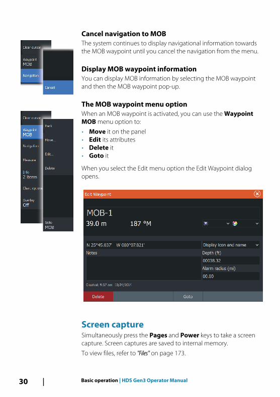
Cancel navigation to MOBThe system continues to display navigational information towardsthe MOB waypoint until you cancel the navigation from the menu.
Display MOB waypoint informationYou can display MOB information by selecting the MOB waypointand then the MOB waypoint pop-up.
The MOB waypoint menu optionWhen an MOB waypoint is activated, you can use the WaypointMOB menu option to:
• Move it on the panel• Edit its attributes• Delete it• Goto it
When you select the Edit menu option the Edit Waypoint dialogopens.
Screen captureSimultaneously press the Pages and Power keys to take a screencapture. Screen captures are saved to internal memory.
To view files, refer to "Files" on page 173.
30 Basic operation | HDS Gen3 Operator Manual

Customizing your system
Customizing the Home page wallpaperThe Home page's wallpaper can be customized. You can select oneof the pictures included with the system, or you can use your ownpicture in .jpg or .png format.
The images can be available on any location that can be seen in thefiles browser. When a picture is chosen as the wallpaper, it isautomatically copied to the Wallpaper folder.
Adjusting panel sizeYou can change the panel size for an active split page. The panelsize can be adjusted for both favorite pages and for predefined splitpages.
1. Activate the System Controls dialog2. Select the adjust splits option in the dialog3. Adjust the panel size by:
- Touch operation: dragging the adjustment icon- Key operation: using the Cursor keys to move the adjustment
icon
3
Customizing your system | HDS Gen3 Operator Manual 31

4. Confirm your changes by tapping one of the panels, selectingthe save option in the menu, or by pressing the Enter key.
The changes are saved to the active favorite or split page.
Data OverlayYou can have data information as overlay on a page. Theinformation can be any data available on the network.
Turning Data overlay on and offYou can turn overlay data on or off for any active page by selectingthe Data overlay icon on the System Controls dialog. When Dataoverlay is on, an orange bar appears above the icon.
Edit overlay dataUse the Edit overlay option on the System Controls dialog toaccess edit menu options to:
• Add a new data overlay to the active panel.• Delete a selected data overlay.• Change a selected data overlay to display different data.• Configure a selected data overlay appearance (digital or analog,
size, etc).• Re-locate an item by selecting and moving it.
Adding new favorite pages1. Select the New icon in the favorite panel on the Home page to
open the page editor dialog
32 Customizing your system | HDS Gen3 Operator Manual

2. Drag and drop page icons to set up a new page3. Change the panel arrangement (only possible for 2 or 3 panels),
if required4. Save the page layout.
The system displays the new favorite page, and the new page isincluded in the list of favorite pages on the Home page.
Edit favorite pages1. Select the edit icon in the Favorite panel:
- Select the X icon on a favorite icon to remove the page- Select the tool icon on a favorite icon to display the page
editor dialog2. Add or remove panels in the page editor dialog3. Save or discard your changes to leave the favorite edit mode.
Customizing your system | HDS Gen3 Operator Manual 33

ChartsThe chart function displays your vessel’s position relative to landand other chart objects. On the chart panel you can plan andnavigate routes, place waypoints, and display AIS targets.
You can overlay a radar image, a StructureScan image or weatherinformation.
The Chart panel
1 Waypoint*
2 Vessel with extension line (extension line is optional)
3 Route*
4 North indicator
5 Grid lines*
6 Range rings*
7 Trail*
8 Chart range scale
9 Range rings interval (only displayed when Range rings areturned on)
4
34 Charts | HDS Gen3 Operator Manual

* Optional chart items. You turn the optional chart items on/offindividually from the Chart settings dialog.
Chart dataThe system is delivered with different embedded cartographydepending on region.
All units support Insight charts from Navico including InsightGenesis. The system also supports charts from Navionics and C-MAPas well as content created by a variety of third party mappingproviders in the AT5 format. For a full selection of available charts,visit www.gofreeshop.com, www.c-map.com, orwww.navionics.com.
Ú Note: In this manual, all possible chart menu options aredescribed. These options vary depending on the chart you areusing.
Ú Note: Insight charts are referred to as Lowrance in the menu.
Charts on chart cards are shared over the Ethernet network, so onlyone chart card per vessel is required.
Ú Note: The system does not automatically switch to embeddedcartography if the chart card is removed. A low-resolution chartwill be displayed until you re-insert the card or manually switchback to the embedded cartography.
Showing dual chart typesIf you have different chart types available - embedded, in the cardslot, or on the Ethernet network - you can show two different charttypes simultaneously on a page with two chart panels.
You can select a dual chart panel by pressing and holding the Chartapplication button on the Home page, or by creating a favoritepage with two chart panels.
Charts | HDS Gen3 Operator Manual 35

Selecting chart typeYou specify the chart type in the Chart panel by selecting one of theavailable chart types in the chart source menu option.
If you have a multiple Chart panel, the chart type is set individuallyfor each chart panel. Activate one of the chart panels, and thenselect one of the available chart types in the chart source menuoption. Repeat the process for the second chart panel, and select analternative chart type for this panel.
Panning the chartYou can move the chart in any direction by:
• Touch operation: dragging your finger on the screen• Key operation: using the Cursor keys to move the cursor to the
edge of the chart panel in the desired direction
Select the Clear cursor menu option or press the X key to removethe cursor and cursor window from the panel. This also centers thechart to the vessel position.
Vessel symbolWhen the system has a valid GPS position lock, the vessel symbolindicates vessel position. If no GPS position is available, the vesselsymbol includes a question mark.
Ú Note: Without a heading sensor on the network, the vessel iconorientates itself using COG (Course over Ground).
Chart scaleYou zoom in and out on the chart by using the zoom (+ or -)buttons, the + or - keys, or two fingers to pinch (zoom out) andspread (zoom in).
Chart range scale and range rings interval (when turned on) areshown in the lower right corner of the chart panel.
36 Charts | HDS Gen3 Operator Manual

Positioning the vessel on the chart panel
Chart orientationSeveral options are available for how the chart is rotated in thepanel. The chart orientation symbol in the panel’s upper rightcorner indicates the north direction.
North up Heading up Course up
North upDisplays the chart with north upward.
Heading upDisplays the chart with the vessel’s heading directed upward.Heading information is received from a compass. If heading is notavailable, then the COG from the GPS is used.
Course upDisplays the chart with the direction the vessel is ACTUALLYtraveling directed upward, which in some cases is not the directionthe vessel is headed.
Look aheadMoves the vessel icon closer to the bottom of the screen so thatyou can maximize your view ahead.
Displaying information about chart itemsWhen you select a chart item, a waypoint, a route, or a target, basicinformation for the selected item is displayed. Select the chart item'spop-up to display all available information for that item. You canalso activate the detailed information dialog from the menu.
Ú Note: If you are viewing applicable C-MAP charts on yoursystem, you can select marine objects to display information
Charts | HDS Gen3 Operator Manual 37

about services and available multimedia (photos) associatedwith the location or object.
Ú Note: Pop-up information has to be enabled in chart settings tosee basic item information.
Using the cursor on the chart panelBy default, the cursor is not shown on the chart panel.
When you activate the cursor, the cursor position window isdisplayed. When the cursor is active, the chart does not pan orrotate to follow the vessel.
Press the X key or select the Clear cursor menu option to removethe cursor and the cursor window from the panel. This also centersthe chart to the vessel position.
Select the Restore cursor menu option to display the cursor in itsprevious location. The Clear cursor and Restore cursor optionsare useful features for toggling between the vessel's currentlocation and the cursor position.
Creating routesYou can create routes as follows on the chart panel.
1. Position the cursor on the chart panel2. Select New followed by New route in the menu3. Continue positioning the remaining routepoints4. Save the route by selecting the save option in the menu.
Ú Note: For more information, refer to "Waypoints, Routes, and Trails" onpage 54.
38 Charts | HDS Gen3 Operator Manual

Find objects on chart panelsYou can search for other vessels or various chart items from a chartpanel.
Activate the cursor on the panel to search from the cursor position.If the cursor is not active, the system searches for items from thevessel's position.
Ú Note: You must have a SIRIUS data package subscription tosearch for fueling stations and an AIS receiver connected tosearch for vessels.
3D chartsThe 3D option provides a three dimensional graphical view of landand sea contours.
Ú Note: All chart types work in 3D mode, but without 3Dcartography for the appropriate area the chart appears flat.
When the 3D chart option is selected, the Pan and the Rotate iconsappear on the chart panel.
Panning the 3D chartYou can move the chart in any direction by selecting the Pan iconand then panning in the desired direction.
Select the Return to vessel menu option to stop panning, and tocenter the chart to vessel position.
Controlling the view angleYou can control the view angle by selecting the Rotate icon andthen panning the chart panel.
Charts | HDS Gen3 Operator Manual 39

• To change the direction you are viewing, pan horizontally• To change the tilt angle of the view, pan vertically
Ú Note: When centered on the vessel position, only the tilt anglecan be adjusted. The view direction is controlled by the chartorientation setting. See "Positioning the vessel on the chart panel" on page37.
Zooming a 3D chartYou zoom in and out on a 3D chart by using the zoom (+ or -)buttons, by using the + and - keys, or the touch method of pinchingand spreading your fingers.
Chart overlayRadar, structure, SonarChart Live (Navionics charts only) andweather data can be displayed as overlay on your chart panel.
Ú Note: Weather overlay is currently only available in the UnitedStates.
When an overlay is selected, the chart menu expands to includebasic menu functions for the selected overlay.
Radar, structure and weather functions are described in separatesections in this manual. For more information about SonarChartLive, see section "SonarChart Live" on page 46.
Insight and C-MAP chartsAll possible menu options for Insight and C-MAP charts aredescribed below. The features and menu options available can varydepending on the charts you use. This section shows menus froman Insight chart.
Ú Note: A menu option is greyed out if it is not available on thechart displayed. For example, raster charts are not available withInsight, so the Raster charts menu option is greyed out whenInsight charts are displayed.
Insight and C-MAP tides and currentsThe system can display Insight and C-MAP tides and currents. Withthis information it is possible to predict the time, level, direction and
40 Charts | HDS Gen3 Operator Manual

strength of currents and tides. This is an important tool whenconsidering planning and navigation of a trip.
In large zoom ranges the tides and currents are displayed as asquare icon including the letter T (Tides) or C (Current). When youselect one of the icons, tidal or current information for that locationare displayed.
Dynamic current data can be viewed by zooming inside a 1-nauticalmile zoom range. At that range, the Current icon changes to ananimated dynamic icon that shows the speed and direction of thecurrent. Dynamic icons are colored in black (greater than 6 knots),red (greater than 2 knots and less than or equal to 6 knots), yellow(greater than 1 knot and less than or equal to 2 knots) or green(equal to or less than 1 knot), depending on the current in thatlocation.
If there is no current (0 knots) this will be shown as a white, squareicon.
Static Current and Tide icons Dynamic Current icons
Charts | HDS Gen3 Operator Manual 41

Insight and C-MAP specific chart optionsOrientation, Look ahead, 3D, and change Chart source (previouslydescribed in this section) are common for all chart types.
PresentationThe charts can be displayed in different imagery styles.
Shaded relief No contours
Raster imagery High resolution bathymetry
42 Charts | HDS Gen3 Operator Manual

Shaded reliefShades seabed terrain.
No contoursRemoves contour lines from the chart.
Raster chartsChanges the view to that of a traditional paper chart.
Raster transparencyControls the transparency of raster imagery.
High resolution bathymetryEnables and disables higher concentration of contour lines.
Insight and C-MAP view options
Chart detail• Full
All available information for the chart in use.• Medium
Minimum information sufficient for navigation.• Low
Basic level of information that cannot be removed, and includesinformation that is required in all geographic areas. It is notintended to be sufficient for safe navigation.
Insight and C-MAP chart categoriesInsight and C-MAP charts include several categories and sub-categories that you can turn on/off individually depending onwhich information you want to see.
Photo overlayPhoto overlay enables you to view satellite photo images of an areaas an overlay on the chart. The availability of such photos is limitedto certain regions, and cartography versions.
You can view photo overlays in either 2D or 3D modes.
Charts | HDS Gen3 Operator Manual 43

No Photo overlay Photo overlay, land only Full Photo overlay
Photo transparencyThe Photo transparency sets the opaqueness of the photo overlay.With minimum transparency settings the chart details are almosthidden by the photo.
Minimum transparency Transparency at 80
Depth paletteControls the Depth palette used on the map.
Paper chartChanges the appearance of the map to a paper chart style.
Safety depthInsight and C-MAP charts use different shades of blue todistinguish between shallow (lighter shades) and deep (darkershades) water. After enabling Safety depth, specify thedesired safety depth limit. The Safety depth sets the limit at whichdepths will be drawn without blue shading.
Depth filterFilters out depth values shallower than the selected depth filterlimit.
44 Charts | HDS Gen3 Operator Manual
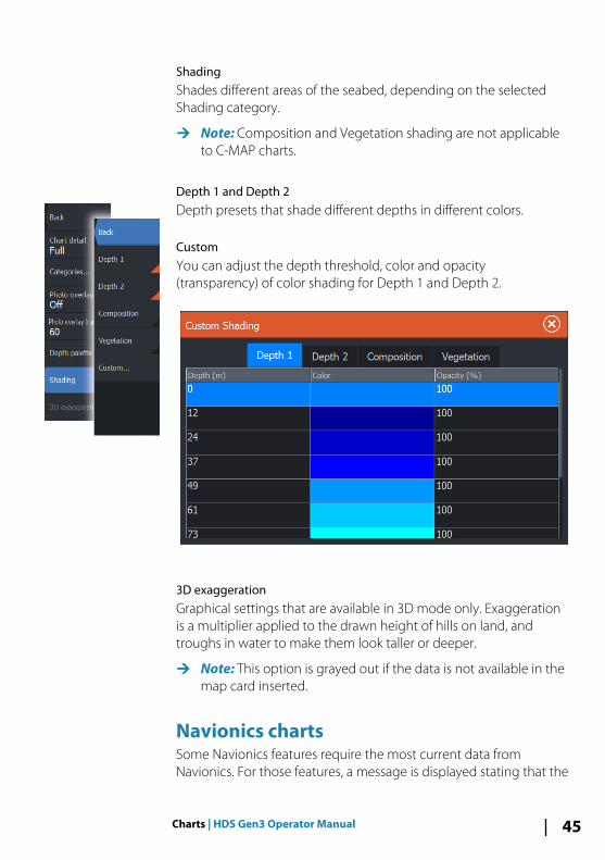
ShadingShades different areas of the seabed, depending on the selectedShading category.
Ú Note: Composition and Vegetation shading are not applicableto C-MAP charts.
Depth 1 and Depth 2Depth presets that shade different depths in different colors.
CustomYou can adjust the depth threshold, color and opacity(transparency) of color shading for Depth 1 and Depth 2.
3D exaggerationGraphical settings that are available in 3D mode only. Exaggerationis a multiplier applied to the drawn height of hills on land, andtroughs in water to make them look taller or deeper.
Ú Note: This option is grayed out if the data is not available in themap card inserted.
Navionics chartsSome Navionics features require the most current data fromNavionics. For those features, a message is displayed stating that the
Charts | HDS Gen3 Operator Manual 45

feature is unavailable if you do not have the appropriate Navionicscharts or chart card inserted. For more information on what isrequired for these features, refer to www.navionics.com
Navionics specific chart optionsOrientation, Look ahead, 3D and change Chart source (previouslydescribed in this section) are common for all chart types.
Community editsToggles on the chart layer including Navionics edits. These are userinformation or edits uploaded to Navionics Community by users,and made available in Navionics charts.
For more information, refer to Navionics information included withyour chart, or to Navionics website: www.navionics.com.
SonarChart LiveSonarChart Live is a real-time feature where the device creates anoverlay of depth contours based on your own live sonar soundings.
In the Navionics chart menu, select Overlay and then SonarChartLive to display it as an overlay on the chart.
When you select SonarChart Live overlay the menu expands todisplay SonarChart Live Options. Use the options to set thetransparency and minimum depth.
TransparencyThe SonarChart Live overlay is drawn on top of other chart data. Thechart data is completely covered at minimum transparency. Adjustthe transparency to allow the chart details to be seen.
Minimum depthAdjusts what SonarChart Live rendering treats as the safety depth.This affects the coloring of the SonarChart Live area. As the vesselapproaches the safety depth, the SonarChart Live area will graduallychange from a simple grey/white to red.
Navionics chart settings
Colored seabed areasUsed for displaying different depth areas in different shades of blue.
46 Charts | HDS Gen3 Operator Manual

Presentation typeProvides marine charting information such as symbols, colors of thenavigation chart and wording for either International or U.S.presentation types.
AnnotationDetermines what area information, such as names of locations andnotes of areas, is available to display.
Chart detailsProvides you with different levels of geographical layer information.
Safety depthThe Navionics charts use different shades of blue to distinguishbetween shallow and deep water.
Safety depth, based on a selected limit, is drawn without blueshading.
Ú Note: The built in Navionics database features data down to 20m, after which it is all white.
Contours depthDetermines which contours you see on the chart down to theselected safety depth value.
Rock filter levelHides rock identification on the chart beneath a given depth.
This helps you to declutter charts in areas where there are manyrocks located at depths well below your vessel's draught.
Charts | HDS Gen3 Operator Manual 47
Navionics view options
Chart shadingShading adds terrain information to the chart.
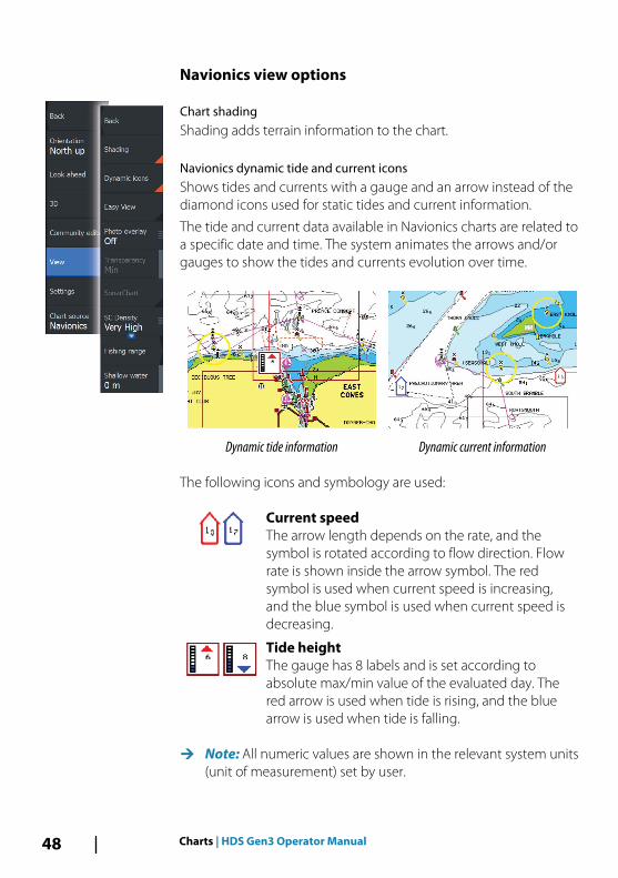
Navionics dynamic tide and current iconsShows tides and currents with a gauge and an arrow instead of thediamond icons used for static tides and current information.
The tide and current data available in Navionics charts are related toa specific date and time. The system animates the arrows and/orgauges to show the tides and currents evolution over time.
Dynamic tide information Dynamic current information
The following icons and symbology are used:
Current speedThe arrow length depends on the rate, and thesymbol is rotated according to flow direction. Flowrate is shown inside the arrow symbol. The redsymbol is used when current speed is increasing,and the blue symbol is used when current speed isdecreasing.
Tide heightThe gauge has 8 labels and is set according toabsolute max/min value of the evaluated day. Thered arrow is used when tide is rising, and the bluearrow is used when tide is falling.
Ú Note: All numeric values are shown in the relevant system units(unit of measurement) set by user.
48 Charts | HDS Gen3 Operator Manual

Easy ViewMagnifying feature that increases the size of chart items and text.
Ú Note: There is no indication on the chart showing that thisfeature is active.
Photo overlayPhoto overlay enables you to view satellite photo images of an areaas an overlay on the chart. The availability of such photos is limitedto certain regions, and cartography versions.
You can view photo overlays in either 2D or 3D modes.
No Photo overlay Photo overlay, land only Full Photo overlay
Photo transparencyThe Photo transparency sets the opaqueness of the photo overlay.With minimum transparency settings the chart details are almosthidden by the photo.
Minimum transparency Maximum transparency
SonarChartThe system supports the Navionics SonarChart feature.
Charts | HDS Gen3 Operator Manual 49

SonarChart displays a bathymetry map showing high resolutioncontour detail and standard navigational data. For moreinformation, refer to www.navionics.com.
SC DensityControls the density of the SonarChart and SonarChart Livecontours.
Fishing rangeSelect a range of depths between which Navionics fills with adifferent color.
This allows you to highlight a specific range of depths for fishingpurposes. The range is only as accurate as the underlying chart data,meaning that if the chart only contains 5 meter intervals for contourlines, the shading is rounded to the nearest available contour line.
No Depth highlight range Depth highlight range: 6 m - 12 m
Shallow water highlightHighlights areas of shallow water.
This allows you to highlight areas of water between 0 and theselected depth (up to 10 meters/30 feet).
No shallow water highlighted Shallow water highlight: 0 m - 3 m
50 Charts | HDS Gen3 Operator Manual

Chart settingsSettings and display options made in the Chart settings page arecommon for all chart panels.
3D boat selectionDetermines which icon to use on 3D charts.
Boat settingsThe boat settings are used when calculating an automatic route.The boat's draught, width and height must be input to useNavionics Dock-to-dock autorouting and easy routing features.
Ú Note: Dock-to-dock Autorouting is not available in Insight units,or in any unit used in U.S. territorial waters.
Range RingsThe range rings can be used to present the distance from yourvessel to other chart objects.
The range scale is set automatically by the system to suit the chartscale.
Charts | HDS Gen3 Operator Manual 51

Extension linesSets the lengths of the heading and course extension lines for yourvessel. For setting extension line lengths on other vessels shown asAIS targets, refer to AIS "Course extension lines" on page 150 lines.
A: Heading
B: Course Over Ground (COG)
The lengths of the extension lines are either set as a fixed distance,or to indicate the distance the vessel moves in the selected timeperiod. If no options are turned on for the vessel then no extensionlines are shown for your vessel.
Your vessel heading is based on information from the activeheading sensor and the COG is based on information from theactive GPS sensor.
SonarChart Live tide correctionWhen selected, the tide correction feature uses information fromnearby tide stations (if available) to adjust the depth values used bySonarChart Live as the sonar is recorded.
Synchronize 2D/3D chartLinks the position shown on one chart with the position shown onthe other chart when a 2D and a 3D chart are shown side by side.
Pop-up informationSelects whether basic information for chart items is displayed whenyou select the item.
Grid linesTurns on/off viewing of longitude and latitude grid lines on thechart.
Hide chartIf the option is set to ON when viewing a Lowrance chart, the chart(background) is not displayed and only the vessel, extensions,waypoints, and routes are displayed on a white background.
52 Charts | HDS Gen3 Operator Manual

Waypoints, Routes, TrailsTurns on/off displaying of these items on chart panels. Also opensthe Waypoints, Routes and Trails dialogs you can use to managethem.
Charts | HDS Gen3 Operator Manual 53

Waypoints, Routes, and Trails
Waypoints, Routes, and Trails dialogsThe Waypoints, Routes, and Trails dialogs give access to advancededit functions and settings for these items.
The dialogs are accessed from the Tools panel on the Home page.
WaypointsA waypoint is a user generated mark positioned on a chart, on aradar image or on the Sonar image. Each waypoint has an exactposition with latitude and longitude coordinates. A waypointpositioned on the Sonar image has a depth value, in addition toposition information. A waypoint is used to mark a position you latermay want to return to. Two or more waypoints can also becombined to create a route.
5
54 Waypoints, Routes, and Trails | HDS Gen3 OperatorManual

Saving waypointsYou can save a waypoint at a selected location by positioning thecursor on the panel, and then selecting the new waypoint option inthe menu.
You can also save a waypoint by pressing the Waypoint key:
• Press once to display the New Waypoint dialog• Press twice to quickly save a waypoint. If the cursor is active, the
waypoint is saved at the cursor position. If the cursor is not active,the waypoint is saved at your vessel's position.
New Waypoint dialog• More options button - Displays more details dialog where you
can change the waypoint name and add notes, specify to displayor hide the waypoint icon and name, select the waypoint symboland waypoint symbol color, note the depth, and specify alarmradius.
• Waypoint symbols button - Displays waypoint symbolalternatives for selection.
• Waypoint symbol colors button - Displays waypoint symbolcoloring alternatives for selection.
• New waypoint button - When selected, the dialog withwaypoint symbol alternatives is displayed. Selecting a waypointsymbol creates the waypoint at cursor or vessel position with theselected symbol. This mode is persistent, the next time youcreate a new waypoint the same dialog opens and if you select asymbol a waypoint is created with the symbol.Instead of selecting a symbol, select the menu button in thebottom-right corner to return to the previous New Waypointdialog. This selection becomes the persistent mode, the next
Waypoints, Routes, and Trails | HDS Gen3 Operator Manual 55

time you create a new waypoint the New Waypoint dialog isdisplayed.
• Save button - (Only available from the New Waypoint and moreoptions dialogs.) Saves the waypoint and closes the NewWaypoint dialog.
• Cancel button - (Only available from the New Waypoint dialog.)Cancels the waypoint creation and closes the New Waypointdialog.
Moving a waypoint1. Select the waypoint you want to move. The waypoint icon
expands to indicate that it is active.2. Activate the menu and select the waypoint in the menu3. Select the move option4. Select the new waypoint position5. Press the Enter key to confirm the new position.
The waypoint is now automatically saved at the new position.
Edit a waypointYou can edit all information about a waypoint from the EditWaypoint dialog.
This dialog is activated by selecting the waypoint's pop-up, or fromthe menu when the waypoint is activated.
The dialog can also be accessed from the Waypoints tool on theHome page.
Delete a waypointYou can delete a waypoint from the Edit Waypoint dialog or byselecting the Delete menu option when the waypoint is activated.
56 Waypoints, Routes, and Trails | HDS Gen3 OperatorManual
You can also delete waypoints from the Waypoints tool on theHome page.
You can delete MOB waypoints the same way.
Waypoint alarm settingsYou can set an alarm radius for each individual waypoint you create.The alarm is set in the Edit Waypoint dialog.
Ú Note: The waypoint radius alarm must be toggled ON in thealarm dialog to activate an alarm when your vessel comeswithin the defined radius. For more information, refer to "Alarmsdialog" on page 176.
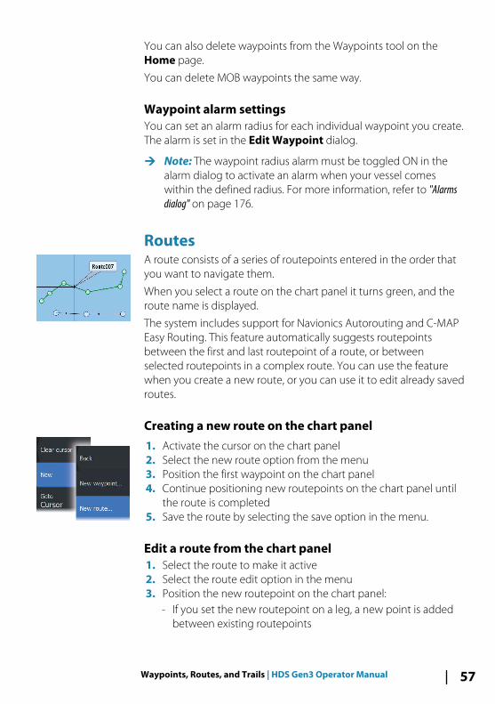
RoutesA route consists of a series of routepoints entered in the order thatyou want to navigate them.
When you select a route on the chart panel it turns green, and theroute name is displayed.
The system includes support for Navionics Autorouting and C-MAPEasy Routing. This feature automatically suggests routepointsbetween the first and last routepoint of a route, or betweenselected routepoints in a complex route. You can use the featurewhen you create a new route, or you can use it to edit already savedroutes.
Creating a new route on the chart panel1. Activate the cursor on the chart panel2. Select the new route option from the menu3. Position the first waypoint on the chart panel4. Continue positioning new routepoints on the chart panel until
the route is completed5. Save the route by selecting the save option in the menu.
Edit a route from the chart panel1. Select the route to make it active2. Select the route edit option in the menu3. Position the new routepoint on the chart panel:
- If you set the new routepoint on a leg, a new point is addedbetween existing routepoints
Waypoints, Routes, and Trails | HDS Gen3 Operator Manual 57

- If you set the new routepoint outside the route, the newroutepoint is added after the last point in the route
4. Drag a routepoint to move it to a new position5. Save the route by selecting the save option in the menu.
Ú Note: The menu changes depending on the selected editoption. All edits are confirmed or cancelled from the menu.
Delete a routeYou can delete a route by selecting the Delete menu option whenthe route is activated. You can also delete routes from the Routestool on the Home page.
Creating routes using existing waypointsYou can create a new route by combining existing waypoints fromthe Routes dialog. The dialog is activated by using the Routes toolon the Home page.
Converting Trails to RoutesYou can convert a trail to a route from the Edit Trail dialog. Thedialog is activated by activating the trail, then selecting the trail'spop-up, or the Trail menu option.
58 Waypoints, Routes, and Trails | HDS Gen3 OperatorManual

The Edit Trails dialog can also be accessed by selecting the Trailstool on the Home page.
Dock-to-dock Autorouting and Easy RoutingThe Dock-to-dock Autorouting and Easy Routing suggest newroutepoint positions based on information in the map and on yourboat's size. Before you can start using this feature the boat draught,width and height must be entered into the system. The boatsettings dialog is automatically displayed if the information ismissing when you start the feature.
Ú Note: Units designed for sale in the U.S. region do not haveAutorouting capabilities. Autorouting features are disabled onall non-U.S. units when they are used in U.S. territorial waters.
Ú Note: It is not possible to start the Dock-to-dock Autorouting orEasy Routing if one of the selected routepoints is located in anunsafe area. A warning dialog is displayed, and you have tomove the relevant routepoint(s) to a safe area to proceed.
Ú Note: If no compatible cartography is available, the Dock-to-dock Autorouting or Easy Routing menu option is not available.Compatible cartography includes C-MAP MAX-N+, Navionics+and Navionics Platinum. For a full selection of available charts,visit www.gofreemarine.com, www.c-map.com orwww.navionics.com.
1. Position at least two routepoints on a new route, or open anexisting route for editing.
2. Select Dock-to-dock Autorouting, followed by:- Entire Route if you want the system to add new routepoints
between the first and the last routepoint of the open route.
Waypoints, Routes, and Trails | HDS Gen3 Operator Manual 59

- Selection if you want to manually select the routepoints thatdefine the limits for the autorouting, then select the relevantroutepoints. Selected routepoints are colored red. Only tworoutepoints can be selected, and the system discards anyroutepoints between your selected start and end points.
3. Select Accept to start the automatic routing.- When the automatic routing is completed the route appears
in preview mode, and the legs are color coded to indicate safeor unsafe areas. Navionics uses red (unsafe) and green (safe),while C-MAP uses red (unsafe), yellow (dangerous) and green(safe).
4. Move any routepoints if required when the route is in previewmode.
5. Select Keep to accept the routepoints positions.6. Eventually repeat step 2 (Selection) and step 3 if you want the
system to automatically position routepoints for other parts ofthe route.
7. Select Save to complete the automatic routing and save theroute.
Dock-to-dock Autorouting and Easy Routing examples• Entire route option used when first and last route points are
selected.
First and last routepoint Result after automatic routing
• Selection option used for autorouting part of a route.
60 Waypoints, Routes, and Trails | HDS Gen3 OperatorManual

Two routepoints selected Result after automatic routing
The Edit Route dialogYou can add and remove routepoints from the Edit Route dialog.This dialog is activated by selecting an active route's pop-up or fromthe menu.
The dialog can also be accessed by using the Routes tool on theHome page.
TrailsTrails are a graphical presentation of the historical path of the vessel,allowing you to retrace where you have travelled. Trails can beconverted to routes from the Edit dialog.
From the factory, the system is set to automatically track and drawthe vessel's movement on the chart panel. The system continues torecord the Trails until the length reaches the maximum points, andthen automatically begins overwriting the oldest points.
Waypoints, Routes, and Trails | HDS Gen3 Operator Manual 61

The automatic tracking function can be turned off from the Trailsdialog.
Creating new TrailsYou can start a new trail from the Trails dialog, activated by usingthe Trails tool on the Home page.
Trails settingsTrails are made up of a series of points connected by line segmentswhose length depends on the frequency of the recording.
You can select to position trail points based on time settings,distance, or by letting the system position a waypoint automaticallywhen a course change is registered.
Ú Note: The Trails option must also be turned ON in the chartsettings to be visible.
62 Waypoints, Routes, and Trails | HDS Gen3 OperatorManual

NavigatingThe navigation function included in the system allows you tonavigate to the cursor position, to a waypoint, or along a predefinedroute.
If autopilot functionality is included in your system, the autopilotcan be set to automatically navigate the vessel.
For information about positioning waypoints and creating routes,refer to "Waypoints, Routes, and Trails" on page 54.
Steer panel
The Steer panel can be used to display information when you arenavigating. It is activated from the Home page, either as a full pagepanel or as part of a multiple panel page.
1 Data fields
2 Vessel heading
3 Bearing to waypoint
4 Destination point
6
Navigating | HDS Gen3 Operator Manual 63

5 Bearing line with allowed off course limitWhen travelling on a route the bearing line shows theintended course from one waypoint towards the next.When navigating towards a waypoint (cursor position, MOB,or an entered latitude and longitude position), the bearingline shows the intended course from the point at whichnavigation was started towards the waypoint.
6 Vessel symbolIndicates distance and bearing relative to the intendedcourse. If the XTE (Cross Track Error) exceeds the defined XTElimit, this is indicated with a red arrow including thedistance from the track line.Refer to "XTE limit" on page 66.
Data FieldsThe Steer panel provides the following information:
XTE Cross track error
SOG Speed over ground
COG Course over ground
POS Position
DTD Distance to destination
TTD Time to destination
Navigate to cursor positionYou can start navigating to a cursor position on any chart, radar, orSonar panel.
Position the cursor at the selected destination on the panel, andthen select the Goto Cursor option in the menu.
Ú Note: The Goto Cursor menu option is not available if you arealready navigating.
Navigate a routeYou can start navigating a route from the chart panel, steer panel, orfrom the Route dialog.
64 Navigating | HDS Gen3 Operator Manual

When route navigation is started, the menu expands and showsoptions for canceling the navigation, for skipping a waypoint, andfor restarting the route from current vessel position.
Starting a route from the chart panelActivate a route on the panel, and then select the route navigationoption from the menu.
You can select a routepoint to start navigating from a selectedposition.
Starting a route from the steer panelSelect the start route option on the menu, and then details from thedialogs.
Start navigating a route from the Route dialogYou can start navigating from the Route dialog, activated by:
• Selecting the Route tool from the Home page• Selecting the route details from the menu
Navigating with the autopilotWhen you start navigation on a system with autopilot functionality,you are prompted to set the autopilot to navigation mode.
Navigating | HDS Gen3 Operator Manual 65

If you choose not to engage the autopilot, the autopilot can be setto navigation mode from the Autopilot Controller later on.
For more information about autopilot functionality, refer to "Autopilot"on page 104.
Navigation settings
Arrival radiusSets an invisible circle around the destination waypoint.
The vessel is considered arrived at the waypoint when it is withinthis radius.
XTE limitThis setting defines how far the vessel can deviate from the selectedroute, if the vessel goes beyond this limit, an alarm is activated.
XTE alarm (Cross track error)Turns on/off the XTE alarm.
Trails Opens the Trails dialog where trails settings can be adjusted andtrails can be converted into routes for navigation. Refer to "ConvertingTrails to Routes" on page 58.
66 Navigating | HDS Gen3 Operator Manual

Logging typeYou can select to record trail points based on time, distance, or byletting the unit position a point automatically when a coursechange is registered.
Specify one of the following logging types in the NavigatingSettings dialog:
• Auto - the unit positions a point automatically when a coursechange is registered.
• Distance - select the Distance field and enter the distance youwant to record.
• Time - select the Time field and enter the time you want torecord.
Phantom LoranEnables use of Phantom Loran positioning system.
Loran settingsDefines Loran chains (GRI) and preferred station for waypoint entry,cursor position and position panel.
The graphic example shows a cursor position window with Loranposition information.
For more information refer to your Loran system documentation.
Navigating | HDS Gen3 Operator Manual 67

SonarThe Sonar function provides a view of the water and bottombeneath your vessel, allowing you to detect fish and examine thestructure of the bottom.
The Sonar image
1 Fish arches
2 History preview*
3 Temperature graph*
4 Depth at cursor
5 Amplitude scope*
6 Zoom (range) buttons
7 Water depth and Water temperature at cursor location
8 Range scale
9 Bottom
* Optional Sonar items.
Ú Note: You turn the optional Sonar items on/off individually.Refer to "view options" on page 76.
7
68 Sonar | HDS Gen3 Operator Manual

Multiple SonarYou can specify the Sonar source for the image in the Sonar panel.You can display two different sources simultaneously, using a splitpanel configuration. For more information how to select the sourcefor a panel, refer to "Source" on page 71.
Zooming the imageYou can zoom the image by:
• using the zoom (+ or -) buttons• pinching or spreading on the screen• using the +/- keys
Zoom level is shown on the bottom left side of the image.
When zooming in, the sea floor is kept near the bottom of thescreen, irrespective of whether it is in auto-range or manual range.
If the range is set considerably less than the actual depth, the unit isnot able to find the bottom when zooming.
If the cursor is active, the unit zooms in where the cursor is pointed.
Zoom barThe zoom bar is displayed when you zoom the image.
Drag the zoom bar vertically to view different parts of the watercolumn.
Using the cursor on the imageThe cursor can be used to measure a distance to a target, to mark aposition, and to select targets.
By default, the cursor is not shown on the image.
When you position the cursor on the image; the screen pauses, thedepth at the cursor position is shown, and the information windowand the history bar are activated.
To remove the cursor and cursor elements from the panel, selectClear cursor or press the X key.
Viewing historyWhenever the cursor is shown on the Sonar panel, the scroll bar isshown at the top of the panel. The scroll bar shows the image you
Sonar | HDS Gen3 Operator Manual 69
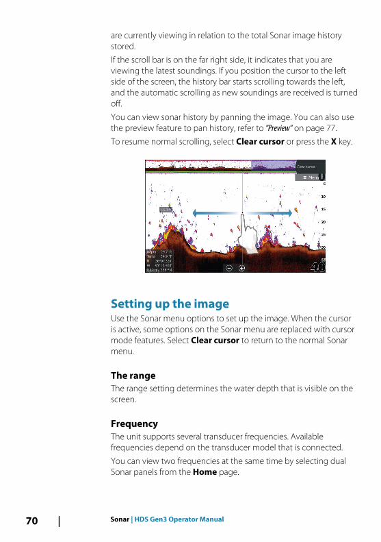
are currently viewing in relation to the total Sonar image historystored.
If the scroll bar is on the far right side, it indicates that you areviewing the latest soundings. If you position the cursor to the leftside of the screen, the history bar starts scrolling towards the left,and the automatic scrolling as new soundings are received is turnedoff.
You can view sonar history by panning the image. You can also usethe preview feature to pan history, refer to "Preview" on page 77.
To resume normal scrolling, select Clear cursor or press the X key.
Setting up the imageUse the Sonar menu options to set up the image. When the cursoris active, some options on the Sonar menu are replaced with cursormode features. Select Clear cursor to return to the normal Sonarmenu.
The rangeThe range setting determines the water depth that is visible on thescreen.
FrequencyThe unit supports several transducer frequencies. Availablefrequencies depend on the transducer model that is connected.
You can view two frequencies at the same time by selecting dualSonar panels from the Home page.
70 Sonar | HDS Gen3 Operator Manual

SensitivityIncreasing Sensitivity shows more detail on the screen. DecreasingSensitivity displays less. Too much detail clutters the screen.Conversely, desired echoes may not be displayed if Sensitivity is settoo low.
Ú Note: Auto Sensitivity is the preferred mode for mostconditions.
Auto sensitivityAuto sensitivity automatically adjusts the sonar return to theoptimal levels. Auto sensitivity can be adjusted (+/-) to yourpreference while still maintaining the auto sensitivity functionality.
ColorlineAllows the user to adjust the colors of the display to helpdifferentiate softer targets from harder ones. Adjusting the Colorlinecan help separate fish and important structures on or near thebottom from the actual bottom.
Adjusting Sensitivity and ColorlineSelect the Sensitivity or Colorline menu options in the Sonar menuand adjust them by dragging the bar vertically or by using theCursor keys.
Ú Note: Minor adjustments can be made by tapping above orbelow the slider bar or pressing the Cursor keys.
Ú Note: When the Sensitivity or Colorline slider bar is displayed, itis automatically selected and adjustments can be made up/down with the Cursor keys.
SourceSelect to specify the source for the image in the selected panel.
You can display two different sources simultaneously, using a splitpanel configuration. Menu controls for each panel are independent.
The source can be the internal Sonar, another MFD on the Ethernetnetwork, or a Sonar module. To define sources, refer to the separateHDS Gen3 Installation manual.
Ú Note: Using two transducers at the same frequency ranges cancause interference between the two, and they can show up on
Sonar | HDS Gen3 Operator Manual 71

the image as vertical lines. To avoid this, set one transducer atone frequency range (such as Medium CHIRP) and the othertransducer at a different frequency range (such as High CHIRP)using the Frequency menu option.
Stop sonarSelect the Stop sonar menu option to stop the sonar from pinging.Use the stop sonar option anytime you want to disable the sonarbut not power off the unit.
Advanced optionsThe Advanced option is only available when the cursor is not active.
Noise rejectionSignal interference from bilge pumps, engine vibration and airbubbles can clutter the image.
The noise rejection option filters the signal interference and reducesthe on-screen clutter.
Surface clarityWave action, boat wakes, and temperature inversion can causeonscreen clutter near the surface. The surface clarity option reducessurface clutter by decreasing the sensitivity of the receiver near thesurface.
Scroll speedYou can select the scrolling speed of the image on the screen. Ahigh scroll speed updates the image fast, while a low scroll speedpresents a longer history.
Ú Note: In certain conditions it may be necessary to adjust thescroll speed to get a more useful image. Such as adjusting theimage to a faster speed when vertically fishing without moving.
Ping speedPing speed controls the rate the transducer transmits the signal intothe water. By default, the ping speed is set to max. It may benecessary to adjust the ping speed to limit interference or to adjustfor specific fishing conditions.
72 Sonar | HDS Gen3 Operator Manual

Manual modeManual mode is an advanced user mode that restricts digital depthcapability, so the unit only processes sonar signals in the selectedrange. This allows the display to continue smooth scrolling if thebottom depth is out of transducer range. When the unit is inmanual mode, you might not receive any depth readings, or youmight receive incorrect depth information.
Start recording log dataYou can start recording log data and save the file internally in theunit, or save it onto a card inserted into the unit’s card reader.
The Log sonar dialog is activated from the Advanced menuoption, or from the Sonar Settings dialog.
When the data is being recorded, there is a flashing red symbol inthe top left corner and a message appears periodically at thebottom of the screen.
FilenameSpecify the name of the recording (log).
File formatSelect a file format from the drop-down, slg (Sonar only), xtf(Structure only*), sl2 (Sonar and Structure) or sl3 (includesStructureScan 3D).
Sonar | HDS Gen3 Operator Manual 73

Ú Note: XTF format is for use only with select 3rd party Sonarviewing tools.
Save toSelect whether the recording is to be saved internally or to amemory card in the card reader.
Bytes per soundingSelect how many bytes per seconds that are to be used whensaving the log file. More bytes yield better resolution, but cause therecord file to increase in size compared to using lower byte settings.
Create StructureMapIf StructureScan is available on the network, you can convert the .sl2or .sl3 logs to StructureMap format (.smf) when recordingcompletes. The log file can also be converted to StructureMapformat from the Files option.
Upload to Insight GenesisFiles are transmitted to Insight Genesis when recording completes,if you are connected to a wireless hotspot. For information aboutwireless hotspots, refer to "Wireless connection" on page 123.
PrivacyIf allowed by your selected Insight Genesis account, you can choosebetween setting the recorded log files as Private or Public at InsightGenesis.
Time remainingShows the remaining allocated space available for recordings.
Stop recording log dataSelect Stop in the Logging Sonar dialog to fully stop the recordingof all sonar log data.
Ú Note: If you have selected the Upload to Insight Genesisoption and are connected to a wireless hotspot, your recordedfiles are transmitted to Insight Genesis when you select Stop.
74 Sonar | HDS Gen3 Operator Manual

Viewing the recorded sounder dataBoth internally and externally stored sounder records may bereviewed when the view sonar log option is selected in the Sonarsettings dialog. Refer to "Sonar settings" on page 78.
The log file is displayed as a paused image, and you control thescrolling and display from the replay menu option.
You can use the cursor on the replay image, and pan the image ason a normal echo image.
If more than one channel was recorded in the selected echo file,you can select which channel to display.
You exit the replay mode by pressing the X key or by selecting theX symbol in the upper right corner of the replay image.
Sonar | HDS Gen3 Operator Manual 75

Sonar view optionsSelect the View option in the Sonar menu to see View options.
Split screen options
Zoom
1 Zoom level
2 Zoom bars
The Zoom mode presents a magnified view of the sounder imageon the left side of the panel. By default, the zoom level is set to 2x.You can select up to 8x zoom from the drop-down menu, using the+/- keys, or the zoom (+ or -) buttons. The range zoom bars on theright side of the display shows the range that is magnified. If youincrease the zooming factor the range is reduced. You see this asreduced distance between the zoom bars.
Bottom lockThe bottom lock mode is useful when you want to view echoesclose to the bottom. In this mode, the left side of the panel showsan image where the bottom is flattened. The range scale is changedto measure from the seabed (0) and upwards. The bottom and thezero line are always shown on the left image, independent of therange scale. The scaling factor for the image on the left side of thepanel is adjusted as described for the Zoom option.
76 Sonar | HDS Gen3 Operator Manual

FlasherThe Flasher mode shows a flasher-style sonar view in the left paneland a normal sonar view in the right panel.
PalettesYou can select between several display palettes optimized for avariety of fishing conditions.
Temperature graphThe temperature graph is used to illustrate changes in watertemperature.
When toggled on, a colored line and temperature digits are shownon the Sonar image.
Depth lineA depth line can be added to the bottom surface to make it easierto distinguish the bottom from fish and structures.
Amplitude scopeThe Amplitude scope is a display of real-time echoes as they appearon the panel. The strength of the actual echo is indicated by bothwidth and color intensity.
PreviewYou can have all available sonar history shown at the top of thesonar screen. The Preview bar is a snapshot of available sonarhistory. You can scroll through sonar history by dragging the
Sonar | HDS Gen3 Operator Manual 77

preview slider horizontally. By default, Preview is turned on whenthe cursor is active.
Fish IDYou can select how you want the echoes to appear on the screen.You can also select if you want to be notified by a beep when a fishID appears on the panel.
Traditional fish echoes Fish symbols Fish symbols and depthindication
Ú Note: Not all fish symbols are actual fish.
Sonar settings
78 Sonar | HDS Gen3 Operator Manual

Internal SonarSelect to make the internal Sonar available for selection in the Sonarmenu. For more information about panel source selection, refer to"Source" on page 71.
When set to off, this option disables the internal Sonar in the unit. Itwill not be listed as a Sonar source for any unit on the network.Select this option on a unit in your network which does not have atransducer connected.
Network SonarYou can share the Sonar images from this unit with other unitsconnected on the Ethernet network.
For more information about how to setup Sonar, refer to theseparate HDS Gen3 Installation manual.
Overlay downscanWhen a DownScan source is connected to your system, you canoverlay DownScan images on the regular Sonar image.
When activated, the Sonar menu expands to include basicDownScan options.
Select Overlay on the Structure options menu to adjust the level ofstructure overlay shown on the screen. You can make adjustmentsusing the Overlay slider bar.
Fishing modeThis feature consists of preset packages of sonar settings designedfor specific fishing conditions.
Ú Note: Selecting the proper fishing mode is critical to optimalsonar performance. If you completed configuration setup atinitial startup, the proper fishing mode has already beenselected.
Fishing mode Depth Palette
General Use ≤ 1,000 ft White background
Shallow Water ≤ 60 ft White background
Fresh Water ≤ 400 ft White background
Sonar | HDS Gen3 Operator Manual 79

Fishing mode Depth Palette
Deep Water ≤ 5,000 ft Deep Blue
Slow Trolling ≤ 400 ft White background
Fast Trolling ≤ 400 ft White background
Clear Water ≤ 400 ft White background
Ice Fishing ≤ 400 ft White background
Reset fishing modeResets selected fishing mode to default settings, allowing you toclear settings adjustments made while using a fishing mode.
Log sonarSelect to start and stop recording of Sonar data. For moreinformation, refer to "Start recording log data" on page 73.
This option is also available from the Advanced option in the Sonarmenu.
View Sonar logUsed to view Sonar recordings. The log file is displayed as a pausedimage, and you control the scrolling and display from the menu.
You can use the cursor on the image, measure distance, and setview options as on a live Sonar image. If more than one channel wasrecorded in the selected Sonar file, you can select which channel todisplay.
You exit the view function by selecting the X in the upper rightcorner or by pressing the X key.
Structure depth offsetSetting for Structure transducers.
All transducers measure water depth from the transducer to thebottom. As a result, water depth readings do not account for thedistance from the transducer to the lowest point of the boat in thewater or from the transducer to the water surface.
To show the depth from the lowest point of the boat to the bottom,do the following. Before setting the Structure offset, measure thedistance from the structure transducer to the lowest point of the
80 Sonar | HDS Gen3 Operator Manual

boat in the water. If, for example, the distance is 0.3 m (1 ft), it will beinput as (minus) - 0.3 m (-1 ft).
To show the depth from the water surface to the bottom, do thefollowing. Before setting the Structure offset, measure the distancefrom the structure transducer to the water surface. If, for example,the distance is 0.3 m (1 ft), it will be input as (plus) 0.3 m (1 ft).
A setting of 0 (zero) causes the depth displayed to be the distancefrom the transducer to the bottom.
InstallationUsed for defining Sonar sources available for selection in the Sourcemenu option. For information about defining sources, refer to theseparate HDS Gen3 Installation manual. For information aboutSource selection, refer to "Source" on page 71.
Sonar | HDS Gen3 Operator Manual 81

StructureScanStructureScan uses high frequencies to provide a high resolution,picture-like image of the seabed.
Ú Note: You must have a StructureScan HD, TotalScan orStructureScan 3D transducer installed to use StructureScanfeatures.
StructureScan provides a wide coverage in high detail withSideScan, while DownScan provides detailed images of structureand fish directly below your boat. The StructureScan page isaccessed from the Home page when the transducer is connected.
Ú Note: StructureScan 3D is also supported. StructureScan 3D is amulti-beam sonar technology that allows anglers to seeunderwater structure and bottom contours in customizable,three-dimensional views. For more information aboutStructureScan 3D, refer to the separate StructureScan 3Ddocumentation.
The StructureScan image
The viewThe StructureScan panel can be set up as a DownScan image, orshowing left/right side scanning.
The DownScan image can also be added as an overlay to thetraditional Sonar image.
8
82 StructureScan | HDS Gen3 Operator Manual

1 Depth
Ú Note: The depth reading depends on the Structuredepth offset setting, refer to "Structure depth offset" onpage 80
2 Temperature
3 Bottom
4 Frequency
5 Zoom (downscan) / Range (sidescan) icons
6 Range scale
Zooming the StructureScan imageYou can zoom a StructureScan image by:
• using the zoom (+ or -) buttons• pinching or spreading on the screen• using the +/- keys
Zoom level is shown on the bottom left side of the panel.
Using the cursor on the StructureScanpanelBy default, the cursor is not shown on the StructureScan image.
When you position the cursor on a DownScan image, the screenpauses, the cursor information window and the history bar areactivated. On a DownScan image, the depth is shown at cursorposition.
When you position the cursor on a SideScan image, the screenpauses, and the cursor information window is activated. On a
StructureScan | HDS Gen3 Operator Manual 83

SideScan image, the left/right distance from the vessel to the cursorare shown at the cursor position.
To remove the cursor and the cursor elements from the panel, pressthe X key or select the Clear cursor option.
Viewing StructureScan historyWhen the cursor is active in a DownScan view, the history bar isshown at the top of the panel.
The highlighted part of the history bar shows the image you arecurrently viewing in relation to the total StructureScan image historystored. You can pan the history by dragging the image or thehighlighted part of the history bar, to the left or right.
In a SideScan view, you can pan the image to see sides and historyby dragging the image left, right, and up.
To resume normal StructureScan scrolling, select Clear cursor orpress the X key.
84 StructureScan | HDS Gen3 Operator Manual

Setting up the StructureScan imageUse the StructureScan menu to set up the image. When the cursoris active, some options in the menu are replaced with cursor modefeatures. Select Clear cursor to return to the normal menu.
RangeThe range setting determines the water depth and SideScan rangethat is visible on the screen.
Auto rangeWhen the range is set to Auto the system automatically sets therange depending on the water depth.
Preset range levelsYou can select between several preset range levels.
StructureScan frequenciesStructureScan supports two frequencies. 455 kHz provides idealrange and image quality in most situations, while 800kHz is used toprovide higher detail in shallow water.
ContrastDetermines the brightness ratio between light and dark areas of thescreen.
To adjust the contrast setting:
1. Select the contrast icon or activate the contrast option in themenu to display the color adjustment bar
2. Drag the bar up or down to get the desired contrast setting orselect Auto contrast.
Ú Note: We recommend that you use Auto contrast.
PalettesYou can select between several display palettes optimized for avariety of fishing conditions.
ViewYou can set up the StructureScan page as a DownScan image, leftonly, right only, or left/right side scanning.
StructureScan | HDS Gen3 Operator Manual 85

Stop sonarUse the Stop sonar menu option when you want to turn off theStructureScan transducer, but not turn off the unit.
Advanced StructureScan settings
Surface clarityWave action, boat wakes and temperature inversions can cause on-screen clutter near the surface.
The surface clarity option reduces surface clutter by decreasing thesensitivity of the receiver near the surface.
Ú Note: By default, surface clarity is set to Low, for optimal imagereturn and clarity.
Noise rejectionSignal interference from bilge pumps, engine vibration and airbubbles can clutter the sonar screen. The noise rejection optionfilters the signal interference and reduces on-screen clutter.
Ú Note: By default, Noise rejection is set to on, for optimal signalreturns and clarity.
Flipping the Structure image left/rightIf required, the left/right SideScanning images can be flipped tomatch the direction of the transducer installation.
Range LinesRange lines can be added to the image to make it easier to estimatedepth (Downscan) and distance (SideScan).
PreviewYou can turn off sonar history preview, have it always shown at thetop of the screen, or have it appear only when the cursor is active.By default, the sonar history preview appears when the cursor isactive.
86 StructureScan | HDS Gen3 Operator Manual

Recording StructureScan dataYou can record StructureScan data and save the file internally in theunit, or onto a memory card as described in "Start recording sonar data" onpage 73.
StructureScan | HDS Gen3 Operator Manual 87

SpotlightScanTo use the SpotlightScan feature, the SpotlightScan transducermust be mounted on your trolling motor and its trolling motorposition sensor mounted on the trolling motor foot pedal. TheSpotlightScan feature can show structure and fish targets aheadand around the boat without disturbing these areas before youhave a chance to fish them. Its trolling motor position sensorensures that the SpotlightScan returns match up correctly with theorientation of your trolling motor. For installation instructions, referto the SpotlightScan Installation Manual.
The SpotlightScan transducer can be used for SpotlightScanimaging, Downscan imaging, or as a conventional broadband/CHIRP transducer.
The SpotlightScan transducer works with most MotorGuide andMinn Kota cable steer trolling motors. Its scanning speed iscontrolled by how fast the trolling motor is rotated with the footpedal.
The SpotlightScan image
1 Water column
9
88 SpotlightScan | HDS Gen3 Operator Manual

2 Bottom
3 Twin scanning beams
SpotlightScan setup
Configuring the heading sensor to the trolling motorYou must configure the heading sensor with the trolling motor footpedal.
1. Select Network from the Settings dialog2. Select Device list3. Select the position sensor (SLS-100)4. Select Calibrate on the device information dialog5. Select your trolling motor foot pedal6. Select Calibrate7. Select OK on the confirmation dialog.
Displaying SpotlightScan imagesTo display SpotlightScan images, the SpotlightScan feature mustfirst be turned on in the Advanced Settings dialog. For moreinformation, refer to "Tools" on page 169.
1. Select the Structure application in the Home page.2. Select the View menu option.3. Select the Spotlight menu option.
You can set up multiple panel pages to view SpotlightScan,broadband sonar, and Downscan images at the same time. Youcannot view SpotlightScan and SideScan images at the same time.
SpotlightScan | HDS Gen3 Operator Manual 89
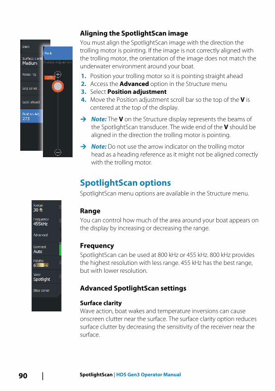
Aligning the SpotlightScan image You must align the SpotlightScan image with the direction thetrolling motor is pointing. If the image is not correctly aligned withthe trolling motor, the orientation of the image does not match theunderwater environment around your boat.
1. Position your trolling motor so it is pointing straight ahead2. Access the Advanced option in the Structure menu3. Select Position adjustment4. Move the Position adjustment scroll bar so the top of the V is
centered at the top of the display.
Ú Note: The V on the Structure display represents the beams ofthe SpotlightScan transducer. The wide end of the V should bealigned in the direction the trolling motor is pointing.
Ú Note: Do not use the arrow indicator on the trolling motorhead as a heading reference as it might not be aligned correctlywith the trolling motor.
SpotlightScan optionsSpotlightScan menu options are available in the Structure menu.
RangeYou can control how much of the area around your boat appears onthe display by increasing or decreasing the range.
FrequencySpotlightScan can be used at 800 kHz or 455 kHz. 800 kHz providesthe highest resolution with less range. 455 kHz has the best range,but with lower resolution.
Advanced SpotlightScan settings
Surface clarityWave action, boat wakes and temperature inversions can causeonscreen clutter near the surface. The surface clarity option reducessurface clutter by decreasing the sensitivity of the receiver near thesurface.
90 SpotlightScan | HDS Gen3 Operator Manual

Noise rejectionSignal interference from bilge pumps, engine vibration and airbubbles can clutter the sonar screen. The noise rejection optionfilters the signal interference and reduces on-screen clutter.
Log sonarYou can Log sonar data and save the file internally in the HDS Gen3unit, or onto a microSD card as described in "Recording Sonar data" onpage 73.
Position adjustmentYou must align the SpotlightScan image with the direction themotor is pointing. Refer to "Aligning the SpotlightScan image" on page 90.
Look AheadYou can make the top half of the image predominant on thedisplay, for a better view of what is in front of you. Select Advancedand then Look Ahead menu options in the Structure menu totoggle it on and off.
ContrastThe contrast determines the brightness ratio between light anddark areas of the screen. This makes it easier to distinguish objectfrom the background.
PalettesYou can select between several display palettes optimized for avariety of fishing conditions.
ViewYou can select between SpotlightScan and DownScan.
Stop sonar Pauses the sonar. Re-select to restart the sonar.
SpotlightScan operation tips• Remove slack in the trolling motor cable to prevent image
distortion.
SpotlightScan | HDS Gen3 Operator Manual 91

• Rotate the trolling motor at a slow, constant speed to achieve thebest results.
• Reducing the range increases the size of the water column,providing the best view of fish activity beneath the boat.
92 SpotlightScan | HDS Gen3 Operator Manual

StructureMapThe StructureMap feature overlays SideScan images from aStructureScan source on the map. This makes it easier to visualizethe underwater environment in relation to your position, and aids ininterpreting SideScan images.
The StructureMap imageThe example below shows a chart panel with Structure overlay,combined with a traditional SideScan panel.
You move around in the chart as usual when you have a Structureoverlay:
• Touch operation: zoom the chart and the scanned image byusing the zoom (+ or -) buttons, or by pinching or spreading onthe screen. Drag on the panel to view the scanned image.
• Key operation: zoom the chart and the scanned image by usingthe +/- keys.
Selecting the Clear cursor option removes the cursor from thepanel, and the chart center is positioned at the vessel.
Activating Structure overlay1. Turn on Structure overlay from the chart menu
- The chart menu is increased to show Structure options- Structure data starts to appear on the chart screen as soon as
Structure overlay is enabled
10
StructureMap | HDS Gen3 Operator Manual 93

2. Select Structure source- Live data is default
Ú Note: Structure overlay can also be activated by selecting asaved StructureMap file in the files browser.
StructureMap sourcesTwo sources can be used to overlay Structure logs on the charts, butonly one can be viewed at a time:
• Live data - Used when StructureScan data is available on thesystem.
• Saved files - These are recorded StructureScan (*.sl2 or *.sl3) datathat are converted to StructureMap (*.smf) format. Saved *.smffiles can be used even if no StructureScan sources are connected.
Live sourceWhen live data is selected, the SideScan imaging history is displayedas a trail behind the vessel icon. The length of this trail variesdepending on available memory in the unit and range settings. Asthe memory fills up, the oldest data is automatically deleted as newdata is added. When increasing the search range, the ping speed ofthe StructureScan transducer is reduced, but the width and thelength of the image history is increased.
Ú Note: Live mode does not save any data. If the unit is turned off,all recent data is lost.
Saved filesWhen Saved files are selected, the StructureMap file is overlaid onthe map based on position information in the file.
If the chart scale is large, the StructureMap area is indicated with aboundary box until the scale is large enough to show Structuredetails.
Saved mode is used to review and examine StructureMap files, andto position the vessel on specific points of interest on a previousscanned area.
Ú Note: When saved files are used as the source, all StructureMapfiles found on the memory card and in the system’s internalmemory are displayed. If there is more than one StructureMapof the same area, the images overlap and clutter the chart. Ifseveral logs of the same area are required, the maps should beput on separate memory cards.
94 StructureMap | HDS Gen3 Operator Manual
StructureMap tips• To get a picture of taller structures (a wreck, etc.) — do not drive
over it, instead, steer the boat so the structure is on the left orright side of your vessel.
• Do not use Autorange when using StructureScan. Set yourstructure range to a significantly greater level (two-to-threetimes) than the water depth to ensure a complete scan and tomaximize conversion accuracy.
• Do not overlap history trails when conducting a side-by-side scanof an area.
Recording StructureScan dataStructureScan data can be recorded from a chart panel withStructure overlay enabled.
StructureScan recordings can also be started from a StructureScanpanel.
When StructureScan data is being recorded, there is a flashing redsymbol and a message appears periodically at the bottom of thescreen.
Ú Note: The message includes information about file size. Keepthe size of your logs to 100MB or less to allow for faster fileconversion.
The recording is stopped by re-selecting the record function.
Converting StructureScan data to StructureMap formatA StructureScan log file (.sl2) is converted to StructureMap format(.smf ) after recording from the recording dialog, or from the filesbrowser.
StructureMap | HDS Gen3 Operator Manual 95

You can create standard or high resolution files. High resolution .smffiles capture more detail, but take longer to convert and are largerthan standard resolution files.
To save disc space it is recommended to remove the StructureScan(.sl2) files after conversion.
Using StructureMap with mapping cardsStructureMap allows you to maintain full chart capability and can beused with embedded cartography as well as Navionics, Insight andother third-party charting cards compatible with the system.
When using StructureMap with mapping cards, copy theStructureMap (.smf ) files to the unit’s internal memory. Werecommend keeping copies of StructureMap files on externalmapping cards.
96 StructureMap | HDS Gen3 Operator Manual

Structure optionsYou adjust the StructureMap settings from the Structure optionsmenu. The menu is available when Structure overlay is enabled.
Not all options are available when saved StructureMap files are usedas the source. Unavailable options are greyed.
RangeSets the search range.
TransparencySets the opaqueness of the Structure overlay. With minimumtransparency settings, the chart details are almost hidden by theStructureMap overlay.
PaletteSelects Structure palette.
ContrastDetermines the brightness ratio between light and dark areas of thescreen.
Water columnShows/hides the water column in Live mode.
If turned OFF schools of bait fish might not be seen on the SideScanimage.
If turned ON the accuracy of the SideScan image on the map mightbe affected by the water depth.
FrequencySets the transducer frequency used by the unit. 800 kHz offers thebest resolution, while 455 kHz has greater depth and rangecoverage.
Clear live historyClears existing live history data from the screen and begins showingonly the most current data.
StructureMap | HDS Gen3 Operator Manual 97

Log Sonar dataRecords StructureScan data.
SourceSelects StructureMap source.
98 StructureMap | HDS Gen3 Operator Manual

Info panelsThe Info panels consist of multiple gauges - analog, digital, and bar- that can be customized to display selected data. The paneldisplays data on dashboards, and you can define up to tendashboards within the panel.
DashboardsA set of dashboard styles are predefined to display vessel,navigation, and angler information.
You switch between the panel’s dashboards by selecting the leftand right arrow buttons on the panel. You can also select thedashboard from the menu.
Vessel dashboard Navigation dashboard Angler dashboard
Ú Note: Additional dashboards can be activated from the menu ifother systems (e.g. CZone) are present on the network.
Customizing the Info panelYou can customize the Info panel by changing the data for each ofthe gauges in the dashboard, by changing the dashboard layout,and by adding new dashboards. You can also set limits for analoggauges.
All edit options are available from the Info panel menu.
Available editing options depend on which data sources areconnected to your system.
11
Info panels | HDS Gen3 Operator Manual 99

Edit a dashboardActivate the dashboard you want to edit, then:
1. Activate the menu2. Select the edit option3. Select the gauge you want to change. Selected gauge is
indicated with a colored background4. Select information to be displayed, configure limits, and
eventually change the source for the information5. Save your changes by selecting the save option in the menu
100 Info panels | HDS Gen3 Operator Manual

VideoThe video function allows you to view videos or camera sources onyour system.
Ú Note: The video images are not shared from the Ethernetnetwork. You can only view the video on the unit connected tothe video source.
The Video panelA video panel can be set up as a single panel, or as one of thepanels on a multiple panel page.
The video image is proportionally scaled to fit into the video panel.Areas not covered by the image are colored black.
Setting up the video panel
Video sourceHDS Gen3 supports one video input channel.
Video standardHDS Gen3 supports NTSC and PAL video. Check the local videostandard or the standard of your cameras.
Adjusting the video imageYou can optimize the video display by adjusting the video imagesettings. Default for all settings: 50%.
12
Video | HDS Gen3 Operator Manual 101

SimulatorThe simulation feature lets you see how the unit works in astationary position and without being connected to sensors orother devices.
Demo modeIn this mode the unit automatically runs through the main featuresof the product; it changes pages automatically, adjusts settings,opens menus, etc.
If you tap on a touchscreen or press a key when demo mode isrunning, the demonstration pauses. After a time-out period, demomode resumes and any changed settings are restored to default.
Ú Note: Demo mode is designed for retail/showroomdemonstrations.
Simulator source filesYou can select which data files are used by the simulator. A set ofsource files is included in your system, and you can import files byusing a card inserted into the card reader. You can also use yourown recorded log data files in the simulator.
13
102 Simulator | HDS Gen3 Operator Manual

Advanced simulator settingsThe Advanced simulator settings allows for manually controlling thesimulator.
GPS sourceSelects where the GPS data is generated from.
Speed, Course and RouteUsed for manually entering values when GPS source is set toSimulated course or Simulated route. Otherwise, GPS data includingspeed and course come from the selected source file.
Set start positionMoves your vessel to the current cursor position.
Ú Note: This option is only available when the GPS source is set toSimulated course.
Simulator | HDS Gen3 Operator Manual 103

Trolling motor autopilotIf a MotorGuide Xi5 trolling motor with Pinpoint GPS is connectedto the network, then the SmartSteer (autopilot) functionality isavailable on your HDS Gen3.
To use trolling motor autopilot functionality, you need thefollowing:
• MotorGuide Xi5 trolling motor with Pinpoint GPS (available fromMotorGuide)
• MotorGuide Pinpoint GPS Gateway (available from MotorGuide)• NMEA 2000 network
For details about installing this equipment, refer to the separateinstallation manuals that come with the equipment.
The Autopilot can automatically control the trolling motor to:
• Maintain a set heading• Maintain the vessel's position• Navigate to the cursor position, to a waypoint, or along a route• Follow pre-defined turn patterns• Control the speed of the trolling motor
Xi5 trolling motor softwareIf at any time there is an update required for your Xi5 trolling motor,instructions will be made available by MotorGuide, and posted onlowrance.com.
Follow the onscreen instructions to update Xi5 software.
Safe operation with the autopilot
Warning: An autopilot is a useful navigational aid,but DOES NOT replace a human navigator.
Switching from automatic navigation tostandby modeTo switch from autopilot to handheld remote or foot pedal steering,set the autopilot to standby mode. You can select standby modefrom the Autopilot Controller or the System Controls dialog.
14
104 Trolling motor autopilot | HDS Gen3 Operator Manual

Autopilot interface
1 Autopilot information bar
2 Autopilot Controller
The Autopilot ControllerThe autopilot is controlled from the Autopilot Controller,activated from the System Controls dialog displayed by pressingthe Power key.
You can select the position of the Autopilot Controller on the page.Refer to "Autopilot settings" on page 109.
Ú Note: As long as the Autopilot Controller is active, youcannot operate the background panel or its menu.
The Autopilot Controller can also be set up as a panel in a splitpanel page by using the Page Editor to make a Favorite page. Forinformation about Favorite pages, refer to "Adding new favorite pages" onpage 32.
The Autopilot information barThe Autopilot information bar is displayed when an autopilotmode is selected. The bar includes information about the autopilotmode and navigational information. The bar is present on all pagesif the autopilot is in an active mode. In the Autopilot settings dialog,
Trolling motor autopilot | HDS Gen3 Operator Manual 105

you can select that the bar is off when the autopilot is in standbymode. Refer to "Autopilot settings" on page 109.
Autopilot control of the trolling motor
Selecting an Arrival modeThe autopilot switches from navigation mode to the selected arrivalmode when your vessel reaches the destination. Arrival mode is setto Standby by default. Before starting a navigation mode or a turnpattern, it is important to select an arrival mode that fits yournavigation needs. Refer to "Arrival mode" on page 110.
Anchor modeMaintains your vessel position at a selected location.
Ú Note: When in anchor mode, your vessel orientation can beaffected by wind or currents.
The following occurs when you select to anchor at:
• WaypointEnables anchor mode when your vessel arrives at a selectedwaypoint.
• CursorEnables anchor mode when your vessel arrives at the cursorposition.
• HereEnables anchor mode at your current location.
Heading Lock modeLocks and maintains the current vessel heading. Use the left andright arrow buttons in the Autopilot Controller to make headingadjustments. To make small heading adjustments, single-select theleft or right buttons. For larger adjustments, select and hold the leftor right buttons.
Standby modeCancels autopilot activity and returns the vessel to handheld remoteor foot pedal steering control.
106 Trolling motor autopilot | HDS Gen3 Operator Manual

Turn pattern steeringSteers the vessel in predefined turn patterns. When you select a turnpattern, the system creates temporary waypoints on the turn. Thelast waypoint on the turn is the final waypoint. When the vesselreaches the final waypoint, the vessel goes into arrival mode. Referto "Arrival mode" on page 110.
Setting up a turn pattern1. Select a turn pattern.2. Enter the desired value(s) in the turn pattern dialog or use
default settings.3. Select the direction of the turn.
Ú Note: Selecting a turn radius smaller than the GPS accuracymay result in incomplete navigation of the turn pattern.
U-turnChanges the current set heading to be 180° in the oppositedirection.
C-turnSteers the vessel in a C-shaped pattern.
Spiral turnSteers the vessel in a spiral with a decreasing or increasing radius.Negative values indicate decreasing radius while positive valuesindicate increasing radius.
Zigzag turnsSteers the vessel in a zigzag pattern.
Square turnMakes the vessel automatically turn 90° after having travelled adefined leg distance.
Lazy S-turnMakes the vessel yaw around the main heading.
Trolling motor autopilot | HDS Gen3 Operator Manual 107

Navigation modeIn Nav. mode you can use the autopilot to steer the boat to cursorposition, to a waypoint position, or along a pre-defined route. Theposition information from the GPS is used to keep the boat on thetrack line towards the destination point.
When you start navigating from an application (from chart, steering,radar, etc) you are prompted to engage the autopilot in Nav. mode.
You can also initiate Nav. mode from the Autopilot Controllerafter navigation is started.
When you reach the destination, the autopilot switches to yourArrival mode setting. Refer to "Autopilot settings" on page 109.
Trolling motor speed controlIn navigation modes (Heading lock mode, Nav. mode, and Turnpattern steering) there are two ways to control speed:
• Prop - selects a target propeller rate (percentage of power)shown as % in the Autopilot information bar.
• Cruise - selects a target cruise control speed shown as mph, kn,or kph in the Autopilot information bar.
Ú Note: Cruise set speed sets the target speed for your vessel.Your vessel may not be able to achieve the set target. TheCruise set speed (not your current speed) is displayed in theAutopilot information bar.
108 Trolling motor autopilot | HDS Gen3 Operator Manual

Speed adjustmentsYou can make speed adjustments on the Heading lock andNavigation control dialogs by selecting the Spd up (+) and Spddown (-) buttons, or by selecting the Set Spd or Set prop optionand entering your desired speed or propeller rate.
Recording and converting a trail to a routeThe Record trail button is used to record and convert a trail or partof a trail to a route.
1. Select Record trail at the desired location to start recording anew trail.
2. Select Save route to select the end location of the route. TheEdit trail dialog appears.
3. Select Create route. The Edit route dialog appears.4. Enter the route details and save it.
Autopilot settings
Ú Note: Options shown on the Autopilot setting dialog variesdepending on if the trolling motor or outboard motor autopilotis active.
Trolling motor autopilot | HDS Gen3 Operator Manual 109

Chart compassYou can select to show a compass symbol around your boat on thechart panel. The compass symbol is off when the cursor is active onthe panel.
Autopilot control locationControls the location of the Autopilot controller on the panel.
Select active autopilotSelects if the autopilot controls the trolling motor or the outboardmotor(s).
Auto hide autopilot bar Controls whether the Autopilot information bar is shown when theautopilot is in Standby mode.
Arrival modeThe trolling motor autopilot switches from navigation mode to theselected arrival mode when your vessel reaches the destination.
Ú Note: Before starting a navigation mode or a turn pattern, it isimportant to select an arrival mode that fits your navigationneeds.
Arrival modes are:
• StandbyCancels autopilot activity and returns the vessel to handheldremote or foot pedal control.
• Heading lockLocks and maintains the last vessel heading.
• AnchorAnchors the vessel at the current destination.
Ú Note: We recommend only using heading lock in open water.
Anchor point setupAnchor points can be saved as a new waypoint, replaced with anexisting waypoint, or set as your current coordinates.
110 Trolling motor autopilot | HDS Gen3 Operator Manual

Anchor points are synced with the Xi5 trolling motor. If any anchorpoints are stored in the motor, they appear in the anchor points list.
Trolling motor autopilot | HDS Gen3 Operator Manual 111

Outboard motor autopilotThe Lowrance SmartSteer interface (Autopilot Controller) providesoutboard motor control. The outboard autopilot can steer on a setheading, to a waypoint, or along a route.
To use outboard autopilot functionality the following are required:
• NAC-1 Autopilot computer• Point-1AP GPS/Heading sensor or RC42N Heading sensor and a
separate GPS antenna• Pump or drive unit connected to the steering system
For details about installing this equipment, refer to the separateinstallation manuals that come with the equipment. Afterinstallation is complete you must set up the outboard autopilot, forinstructions refer to the HDS Gen3 Installation Manual.
Safe operation with the autopilot
Warning: An autopilot is a useful navigational aid,but DOES NOT replace a human navigator.
Autopilot control of the outboard motor(s)The autopilot is controlled from the Autopilot Controller,activated from the System Controls dialog displayed by pressingthe Power key.
The Autopilot Controller can also be set up as a panel in a splitpanel page by using the Page Editor to make a Favorite page.
The options in the Autopilot Controller vary with active mode.
Selecting the trolling or outboard motor autopilotIf autopilot control of the trolling motor and outboard motor areinstalled on the same vessel, only one of the auto steering optionscan be active at a time. When both options are installed, a button toswitch between them is included in the Autopilot Controller.
Mode overview
15
112 Outboard motor autopilot | HDS Gen3 Operator Manual

Standby modeStandby mode is used when you want to disable the autopilot andmanually steer the boat.
The autopilot information bar is hidden when the autopilot is inStandby mode. To view the autopilot bar, disable Autohide fromthe Autopilot settings dialog.
Power steer modeIn this mode you use the port and starboard arrow buttons in theAutopilot Controller to turn the outboard motor(s). The motorturns as long as the button is pressed and remains at the set angle.
Auto modeIn AUTO mode, the autopilot steers the boat automatically on a setheading.
When the mode is activated, the autopilot selects the currentcompass heading as the set heading.
Ú Note: Strong wind and current might affect the steering of thevessel in AUTO mode. While the autopilot compensates for anyheading change, the wind and current could cause the courseof the boat to differ significantly from the heading.
Outboard motor autopilot | HDS Gen3 Operator Manual 113

Changing set heading in AUTO modeYou adjust the set heading by using the port and starboard (1 or 10degrees) arrow buttons in the Autopilot Controller.
When you select the button, an immediate heading change takesplace. The new heading is maintained until a new heading is set oruntil you select another mode for the autopilot.
Turn pattern steeringThe autopilot includes a number of automatic turn steering featureswhen the autopilot is in AUTO mode.
Ú Note: Turn pattern steering for outboard motors uses headinginformation only, while turn pattern steering for the trollingmotor uses both GPS and heading information. Therefore, withoutboard turn pattern steering, waypoints in the turns are notcreated and displayed as they are with trolling motor turnpatterns.
Initiating a turnYou start the turn by selecting the relevant turn icon, followed byselecting the port or starboard options in the turn dialog to selectthe turn direction.
Stopping the turnYou can stop the turn from within the turn dialog.
At any time during a turn you can select Autopilot standby in theSystem Controls dialog to return to STBY mode and manualsteering.
Turn variablesThe turn steering options have settings that you can adjust beforeyou start a turn and at any time when the boat is in a turn.
U-turnU-Turn changes the current set heading to be 180° in the oppositedirection.
The turn rate is identical to Rate limit settings. This cannot bechanged during the turn.
C-turnSteers the vessel in a circle.
114 Outboard motor autopilot | HDS Gen3 Operator Manual

You can adjust the Rate of turn from the turn dialog before the turnis initiated and during the turn. Increasing the turn rate makes thevessel turn a smaller circle.
Spiral turnSpiral-turn makes the vessel turn in a spiral with a decreasing orincreasing radius. You set the initial radius before the turn isinitiated, and the change per turn during the turn. If the change perturn is set to zero, the vessel turns in a circle. Negative valuesindicate decreasing radius while positive values indicate increasingradius.
Zigzag turnsSteers the vessel in a zigzag pattern.
For navigating in a zigzag pattern, you set the initial headingchange before the turn is started.
During the turn you can alter the main heading, the headingchange, and the leg distance.
Square turnMakes the vessel automatically turn 90° after having travelled adefined leg distance.
At any time during the turn you can change the main heading andthe distance of the leg until the vessel makes a new 90° turn.
Lazy S-turnMakes the vessel yaw around the main heading.
You set the selected heading change before the turn is started.
During the turn you can alter the main heading, the headingchange and the turn radius from within the turn dialog.
Depth contour tracking, DCTTM
If the system has Sonar input, the autopilot can be set to follow adepth contour.
Warning: Do not use this feature unless the seabed issuitable. Do not use it in rocky waters where the depthis varying significantly over a small area.
Outboard motor autopilot | HDS Gen3 Operator Manual 115

Use the following process to initiate DCT steering:
1. Ensure that you have depth reading on the panel or on aseparate depth instrument.
2. Steer the boat to the depth you want to track, and in thedirection of the depth contour.
3. Activate AUTO mode, select depth contour steering andmonitor the depth reading.
4. Select the port or starboard option in the turn dialog to initiatethe depth contour steering to follow the bottom sloping tostarboard or to port:
Port option(depth decreases to port)
Starboard option(depth decreases to starboard)
The following parameters are available for depth contour tracking:
Depth gainThis parameter determines the ratio between commanded rudderand the deviation from the selected depth contour. The higherdepth gain value the more rudder is applied.
If the value is too small, it takes a long time to compensate fordrifting off the set depth contour, and the autopilot fails to keep theboat on the selected depth.
116 Outboard motor autopilot | HDS Gen3 Operator Manual

If the value is set too high, the overshoot increases and the steeringis unstable.
Contour Cross Angle (CCA)The CCA is an angle that is added to or subtracted from the setcourse.
With this parameter you can make the boat yaw around thereference depth with lazy-s movements.
The larger the CCA, the bigger yawing is allowed. If you the CCA setto zero there are no lazy-s movements.
Ref. depthUse this parameter to change the reference depth which the boatwill yar around when making Lazy-s movements.
Course modeThe Course mode combines the heading information from thesteering compass and the positioning information from the GPS. Inthis mode, the vessel is steered along a calculated track line in adirection set by the user. If the vessel’s heading is drifting away fromthe original heading due to current and/or wind, the vessel followsthe line with a crab angle.
1. Turn the vessel to the desired heading.2. Activate Course mode. The autopilot draws an invisible bearing
line based on the current heading from the boat’s position.
In Course mode, the autopilot uses position information to calculatethe cross track error, and to automatically keep your track straight.
Use the port and starboard (1 or 10 degrees) arrow buttons in theAutopilot Controller to change the bearing line while in Coursemode.
Outboard motor autopilot | HDS Gen3 Operator Manual 117

NAV modeYou can use the autopilot to automatically steer the boat to thecursor position, to a waypoint position, or along a pre-defined route.The position information from the GPS is used to change the courseto steer to keep the boat on the track line towards the destinationpoint.
Warning: NAV mode should only be used in openwaters.
Ú Note: To use navigation mode, the system must have validposition input.
When the vessel reaches the arrival circle for a waypoint, theautopilot gives an audible warning and displays a dialog with thenew course information. If the required course change to the nextwaypoint is less than 30°, the autopilot automatically changes thecourse. If the required course change to next waypoint in a route ismore than 30°, you are prompted to verify that the upcomingcourse change is acceptable.
Waypoint arrival circle
The Arrival radius defines the point at which a turn is initiated whenyou are navigating a route.
118 Outboard motor autopilot | HDS Gen3 Operator Manual

The arrival circle (1) should be adjusted according to boat speed.The higher the speed, the wider the circle. The intention is to makethe autopilot start the heading change in due time to make asmooth turn onto the next leg.
The figure below may be used to select the appropriate waypointcircle when creating the route.
X axis = Boat speed in knotsY axis = Arrival circle, radius in 1/100 Nm
Example: With the speed of 20 knots you should use a waypointcircle with radius 0.09 Nm.
Ú Note: The distance between any waypoints in a route must notbe smaller than the radius of the waypoint arrival circle.
Start automatic navigating1. Start navigating a route, or start navigation to a waypoint or to
the cursor position from the Chart panel or from the Steer panel.2. Engage the autopilot in NAV mode when prompted.
Outboard motor autopilot | HDS Gen3 Operator Manual 119

- If you reject this request, you can later start NAV mode fromthe Autopilot Controller.
3. Accept the required course change to activate NAV mode.- If the course change is not accepted within 8 seconds, the
dialog is removed and the autopilot remains in the currentactive mode.
After the autopilot is engaged in NAV mode, the AutopilotController shows NAV steering options.
RestartRestarts the navigation from the vessel’s current position.
CancelCancels active navigation and deselects the current route orwaypoint navigation. The autopilot is switched to AUTO mode,steering the vessel on the heading that was active when the Cancelbutton was selected.
Ú Note: This is different from selecting Standby mode which doesnot stop current navigation. From Standby mode you can laterrestart the active route.
SkipSkips the active waypoint and steers towards the next waypointwhen you are navigating a route.
120 Outboard motor autopilot | HDS Gen3 Operator Manual

Autopilot settings
Ú Note: Options shown on the Autopilot setting dialog variesdepending on if the trolling motor or outboard motor autopilotis active.
Chart compassYou can select to show a compass symbol around your boat on thechart panel. The compass symbol is off when the cursor is active onthe panel.
Autopilot control locationControls the location of the Autopilot controller on the panel.
Select active autopilotSelects if the autopilot controls the trolling motor or the outboardmotor(s).
Autopilot data sourcesProvides automatic and manual data source selection for youroutboard autopilot.
Outboard motor autopilot | HDS Gen3 Operator Manual 121

Auto hide autopilot bar Controls whether the Autopilot information bar is shown when theautopilot is in Standby mode.
CommissioningUsed to calibrate your outboard motor’s steering (Cablesteer orHydraulic steering) with the NAC-1.
Steering responseUsed to increase or decrease the steering sensitivity. A low responselevel reduces the rudder activity and provides a more loose steering.A high response level increases the rudder activity and providesmore tight steering. Too high a response level will cause the boat tomake “S” movements.
122 Outboard motor autopilot | HDS Gen3 Operator Manual

Wireless connectionGoFree wireless connectivity gives you the ability to:
• Use a wireless device to remotely view (smartphone and tablet)and control the system (tablet only).
• Access the GoFree Shop.• Upload your Sonar logs to create custom maps at Insight
Genesis.• Download software updates• Connect to third party applications
Ú Note: Maps, charts, software updates, and other data files canbe large. Your data provider may charge you based on theamount of data you transfer. If you are unsure contact theservice provider for information.
The unit includes:
• Built-in wireless functionality for connecting to the internet andwireless devices such as smartphones and tablets.
• Built-in Bluetooth wireless technology.The built-in Bluetooth wireless technology gives you the abilityto connect the unit to Bluetooth enabled devices. For moreinformation, refer to "Bluetooth wireless technology" on page 126.
Initial configuration and setup of the built-in wireless functionality isdescribed in your system's Installation Manual.
Connect and disconnect from a wirelesshotspotTo connect to a wireless hotspot, select the Wireless option in theSystem Controls dialog and then select Not Connected. This opensthe Wireless Devices dialog. Use this dialog to select the desiredhotspot, enter the login information and then select Connect.Connecting to a wireless hotspot changes the wireless mode toClient mode. In this mode, you can access the GoFree Shop.
To disconnect from a wireless hotspot, select the Wireless option inthe System Controls dialog, then select Connected hotspot_name, andthen Disconnect. This changes the wireless mode to Access point
16
Wireless connection | HDS Gen3 Operator Manual 123

mode. In this mode, you can connect a wireless device so that Appssuch as GoFree Link can access the vessel's navigation information.
GoFree ShopThe wireless must be connected to an external wireless hotspot inorder to access the GoFree Shop.
At the GoFree Shop you can browse, purchase and downloadcompatible content for your system including navigation charts andInsight Genesis Maps. When you log on, the system automaticallygives you a notification if a new software version is available for yoursystem. If an update is available, you can download it to a card slotor defer the download until later. If you defer the download untillater, the notification is available in the About dialog accessible fromthe System Settings.
GoFree Link The wireless functionality lets you use a wireless device to remotelyview (smartphone and tablet) and control the system (tablet only).The system is viewed and controlled from the wireless device by theGoFree Link Apps downloaded from their relevant Application store.When remote control is accepted, the active page is mirrored to thewireless device.
Ú Note: To use smartphones and tablets to view and control thesystem, wireless functionality must be disconnected from thewireless hotspot (in Access point mode).
Ú Note: For safety reasons, Autopilot and CZone functions cannotbe controlled from a wireless device.
Connecting a tabletInstall the GoFree App on the tablet before following thisprocedure.
1. Set the internal wireless to Access Point mode. To do this,select the Wireless devices page in the Wireless settingsdialog and then select the Internal wireless. Next, select theMode option and then select Internal Access Point.
2. Select a device on the Wireless devices page to view itsnetwork key.
3. Navigate to the wireless network connection page on the tablet,and find the unit or GoFree wireless xxxx network. If more than
124 Wireless connection | HDS Gen3 Operator Manual

one is in range, review the Wireless devices page on the unitto confirm which wireless device is connected to the unit.
4. Enter the Network Key in the tablet to connect to the network.5. Open the GoFree application - the unit should be automatically
detected. The name displayed will be either the default, or thatassigned in the Device Name setting. If the unit does notappear, follow the on screen instructions to manually find thedevice.
6. Select the graphic icon of the unit. The unit displays a promptsimilar to the following:
7. Select Yes for one-time connection, or Always if device is to beremembered for regular connection. This setting can bechanged later if required.
Ú Note: The internal wireless module only supports GoFreeconnection to itself. Other units connected on the network arenot visible.
Connecting a smartphoneInstall the GoFree App on the smartphone before following thisprocedure.
1. Set the internal wireless to Access Point mode. To do this,select the Wireless devices page in the Wireless settingsdialog and then select the unit's Internal Wireless. Next, selectthe Mode option and then select Internal Access Point.
2. Select a device on the Wireless devices page to view itsNetwork Key.
3. Navigate to the wireless network connection page on thesmartphone, and find the unit or GoFree wireless xxxx network. Ifmore than one is in range, review the Wireless devices pagefrom the unit's Wireless settings dialog to confirm whichwireless device is connected to the unit.
4. Enter the Network Key in the smartphone to connect to thenetwork.
5. Open the GoFree application on the smartphone, the unitshould be automatically detected. The name displayed will beeither the default, or that assigned in the Device Name setting. If
Wireless connection | HDS Gen3 Operator Manual 125

the unit does not appear, follow the on screen instructions tomanually find the device.
The MFD's display is shown on the smartphone. To change theMFD's display on the smartphone, use the MFD to change thedisplay on the MFD. The display change on the MFD is reflected onthe smartphone.
Uploading log files to Insight GenesisTo upload a recorded Sonar log file to Insight Genesis, select the fileyou want to upload from the Files panel and select the upload toInsight Genesis option.
Ú Note: You must be connected to a wireless hotspot to uploadrecorded log files to Insight Genesis.
Ú Note: Recorded log files can also be uploaded to InsightGenesis if you have specified Upload to Insight Genesis inthe Log Sonar dialog. For more information, refer to "StartRecording log data" on page 73.
Bluetooth wireless technologyThe HDS Gen3 includes built-in Bluetooth wireless technology. Toconnect the HDS Gen3 to Bluetooth enabled devices you must pairthem.
Pairing Bluetooth devicesTo pair the unit with a Bluetooth enabled device, do the following:
1. Turn on the Bluetooth enabled device so that it is able to sendand receive Bluetooth signals.
2. Open the Wireless settings dialog in the HDS Gen3 and turn onBluetooth, if it is not already enabled.
3. Select Bluetooth devices. The system searches for Bluetoothenabled devices, and lists them in the Bluetooth Devices dialog.
126 Wireless connection | HDS Gen3 Operator Manual

Devices that are already paired are listed under Paired Devices.Devices that are not paired are listed under Other Devices.
4. Select the Bluetooth enabled device you want to pair with in thelist under Other Devices. The Bluetooth Device Detailsdialog opens.
5. Select Pair to pair the HDS Gen3 to the device.6. Repeat these steps for each device you want to pair with the
HDS Gen3.
Pairing with dual Power-PolesIf dual Power-Poles are installed on your boat, the one that is pairedfirst automatically becomes Port and the second is set toStarboard in the Power-Pole controls.
To swap them around, unpair the connected Power-Poles. Andthen, toggle off and on Bluetooth in the Wireless settings dialog toreset the Bluetooth memory. Once Bluetooth has been toggledback on, proceed in pairing the Power-Poles in the correct order.
Wireless settingsProvides configuration and setup options for the wirelessfunctionality.
Wireless connection | HDS Gen3 Operator Manual 127

Connect to a wireless hotspotDisplays the Wireless device dialog that you can use to connect thewireless functionality to a wireless hotspot.
Remote controllersWhen a wireless device (smart phone or tablet) is connected, itshould appear in the Remote controllers list. Selecting ‘Always allow’means the device can automatically connect without needing apassword each time. This menu also allows you to disconnectdevices that no longer require access.
Wireless devicesThis dialog shows the internal wireless and any connected WIFI-1devices, as well as their IP and channel number. Selecting theinternal wireless or a WIFI-1 device provides additional detail.
To view and change internal wireless detail values (Network Name(SSID), Network Key, or Channel) the internal wireless must be inAccess Point (Internal Wifi) mode. To select a network (hotspot) toconnect to, the internal wireless must be in Client Mode. Use theMode option to change modes.
Client settingsDisplays information about the wireless hotspot your unit isconnected to or the last one your unit was connected to. You can
128 Wireless connection | HDS Gen3 Operator Manual

select the hotspot in the dialog to set it as a hotspot you want toalways connect to when in range or you can select to delete it.
AdvancedInitiates the Iperf and DHCP Probe tools that help in fault-findingand setting up the wireless network.
Ú Note: Iperf and DHCP Probe are tools provided for diagnosticpurposes by users familiar with network terminology andconfiguration. Navico is not the original developer of thesetools, and does not provide support related to their use.
BluetoothEnables the built-in Bluetooth wireless technology functionality.
Bluetooth devicesDisplays the Bluetooth Device list dialog. Use the Bluetooth DeviceList dialog to pair or remove pairing to Bluetooth enabled devices.
Wireless connection | HDS Gen3 Operator Manual 129

RadarThe radar panel can be set up as a full screen view or combinedwith other panels.
The radar image can also be displayed as an overlay on a chartpanel. For more information, see "Chart overlay" on page 40.
Ú Note: Radar overlay requires data from a heading sensor orcompass to ensure proper orientation with the chart.
The Radar panel
1 Orientation
2 Range
3 Heading line*
4 Cursor
5 Compass*
6 Cursor position window
7 Range rings*
8 Range markers*
17
130 Radar | HDS Gen3 Operator Manual

* Optional radar symbology.
Radar symbology can be turned ON/OFF collectively from the Radarmenu, or individually as described in Radar settings panel.
Radar overlayYou can overlay the Radar image on the Chart. This can help you toeasily interpret the radar image by correlating the radar targets withcharted objects.
When the radar overlay is selected, basic radar operational functionsare available from the Chart panel’s menu.
Selecting radar overlay source on chart panelsTo select the radar source of the radar overlay displayed on thechart panel, use the Radar options and then Source chart panelmenu options to select the radar source.
For chart pages with more than one chart with radar overlay, it ispossible to set up different radars sources for each chart panel.Activate one of the chart panels and then select one of the availableradars in the radar source menu option. Repeat the process for thesecond chart panel with radar overlay, and select an alternativeradar for this panel.
Radar operational modesThe radar’s operational modes are controlled from the HDS Gen3unit. The following modes are available:
OffThe power to the radar scanner is turned off.
StandbyThe power to the radar scanner is on, but the radar is nottransmitting.
TransmitThe scanner is on and transmitting. Detected targets are drawn onthe radar PPI (Plan Position Indicator).
Radar | HDS Gen3 Operator Manual 131

Radar RangeYou adjust radar range by selecting the zoom (+ or -) buttons on theradar panel or using the zoom (+ or -) keys.
Using the cursor on a radar panelBy default, the cursor is not shown on a radar panel.
When you position the cursor on the radar panel, the cursorposition window is activated and the cursor menu options aredisplayed.
To remove the cursor and cursor elements from the panel, selectClear cursor or press the X key.
Adjusting the radar imageYou may be able to improve the radar image by adjusting the radarsensitivity, and by filtering out the random echoes from sea andweather conditions.
You can adjust the image settings from the radar menu.
Directional clutter rejection(Broadband 4G Radar only)
This mode automatically works when GAIN = AUTO and SEA =HARBOR or OFFSHORE. The purpose is to allow smaller vessels to beseen in the leeward direction of the sea clutter. The GAIN of theradar receiver is increased dynamically during the sweep, in theleeward direction, for increased target sensitivity in heavier seastates.
When GAIN or SEA = MANUAL, the Directional Clutter Rejectionmode will be OFF (non-directional).
In addition, CALM, MODERATE or ROUGH STC Curve settings areavailable in the Radar options menu to better optimize the radarimage to your liking.
GainThe gain controls the sensitivity of the radar receiver.
A higher gain makes the radar more sensitive to radar returns,allowing it to display weaker targets. If the gain is set too high, theimage might be cluttered with background noise.
132 Radar | HDS Gen3 Operator Manual

Gain has a manual and an automatic mode. You toggle betweenautomatic and manual mode in the slide bar.
Sea clutterSea clutter is used to filter the effect of random echo returns fromwaves or rough water near the vessel.
When you increase Sea clutter, filtering the on-screen clutter causedby the echoes of waves is reduced.
The system includes predefined Sea clutter settings for harbor andoffshore conditions, in addition to the manual mode where you canadjust the settings. You select Sea clutter modes from the menu.You can only adjust the Sea clutter value in manual mode.
Rain clutterRain clutter is used to reduce the effect of rain, snow or otherweather conditions on the radar image.
The value should not be increased too much as this may filter outreal targets.
Advanced radar options
Noise Rejection(Broadband 4G radar only)
The Noise Rejection control sets the amount of noise filteringapplied by the radar. Target sensitivity is increased at longer rangeswhen this control is set to Low or High, but does cause some loss oftarget discrimination.
Tip: To get maximum range performance from Broadband 4GRadar, transmit on one range only, set the Noise Reject control toHigh and the threshold as low as possible. The default is 30% for lessclutter on the screen. If OFF is selected for the HDS Gen3, the rangeperformance is about equal to 3G radar. In some areas whereextreme high interference may exist, try OFF for best radar image.
Radar thresholdThe threshold sets required signal strength for the lowest radarsignals. Radar returns below this limit are filtered and are notdisplayed.
Radar | HDS Gen3 Operator Manual 133

Default value: 30%.
Target expansionTarget expansion increases the length of targets in range, makingthem easier to see.
Rejecting radar interferenceInterference could be caused by radar signals from other radar unitsoperating in the same frequency band.
A high setting reduces the interference from other radars.
In order not to miss weak targets, the interference rejection shouldbe set to low when no interference exists.
Target separation(Broadband 4G Radar only)
The Target separation control allows you to control the targetdiscrimination of the radar (separation between objects is moreprominent).
Fast scan(Broadband Radar only).
Sets the speed of the radar antenna rotation. This option gives fastertarget updates.
Ú Note: Maximum speed may not be achieved depending on theradar Settings, Mode, and Range selected. The radar will onlyrotate as fast as the current control settings allow.
Sea StateSet the Sea State control according to current sea conditions forbest sea clutter rejection.
Target boost(3G and 4G Broadband, and Pulse Radar only)
The target boost control increases pulse length or reduces radarbandwidth to make targets appear larger in range and increaseradar sensitivity.
134 Radar | HDS Gen3 Operator Manual

Radar view options
Radar symbologyRadar symbology defined in the Radar Settings panel can be turnedon/off collectively. See the radar panel illustration showing optionalradar items.
Target trailsYou can set how long the trails generated from each target on yourradar panel remain. You can also turn OFF target trails.
Ú Note: True motion is recommended when using Target trails
Clearing target trails from the panelWhen target trails are displayed on the panel, the radar menuexpands to include an option where you can clear target trails fromyour radar panel temporarily. The target trails start to appear againunless you switch them off as described above.
The radar paletteDifferent colors (palettes) can be used to represent detail on yourradar panel.
Radar orientationRadar orientation is indicated on the upper left corner of the radarpanel as either HU (Heading UP), NU (North Up) or CU (Course up).
Heading upRotates the radar image to display the current heading directly upon the radar image.
North upRotates the radar image with the north direction upwards.
Course upRotates the radar image to display the current navigation coursedirectly up.
This option works only when the system is navigating an activeroute. If you are not navigating an active route, the heading uporientation is used until the navigation function is started.
Radar | HDS Gen3 Operator Manual 135

Positioning the radar centerYou can move the radar PPI (Plan Position Indicator) center todifferent positions within the radar panel, and select how yourvessel symbol moves on the radar image.
Radar motion is indicated on the upper left corner of the radar panelas either TM (True motion) or RM (Relative motion).
The radar position can only be changed when the radar istransmitting.
Center Look ahead Custom offset
CenterDefault setting. The radar PPI center is centered on the radar panel.
Look AheadMoves the radar PPI center to the bottom of the panel to maximizethe view ahead.
OffsetAllows you to move the PPI center to any location on the radarpanel.
1. Select the offset option from the menu2. Move the cursor to where you want to position the radar center3. Confirm the setting by selecting the save offset option in the
menu.
136 Radar | HDS Gen3 Operator Manual

EBL/VRM markersThe electronic bearing line (EBL) and variable range marker (VRM)allows quick measurements of range and bearing to vessels andlandmasses within radar range. Two different EBL/VRMs can beplaced on the radar image.
The EBL/VRMs are by default positioned from the center of thevessel. It is, however, possible to offset the reference point to anyselected position on the radar image.
When positioned, you can turn the EBL/VRM on/off by selecting therelevant markers on the data bar, or by deselecting the marker fromthe menu.
Defining an EBL/VRM marker1. Ensure that the cursor is not active2. Activate the menu, select EBL/VRM, then select EBL/VRM 1 or
EBL/VRM 2- The EBL/VRM is now positioned on the radar image
3. Select the adjustment option from the menu if you need toreposition the marker, then adjust the marker by dragging it intoposition on the radar image
4. Select the save option in the menu to save your settings
Placing EBL/VRM markers by using the cursor1. Position the cursor on the radar image2. Activate the menu3. Select one of the EBL/VRM markers
Radar | HDS Gen3 Operator Manual 137

- The EBL line and the VRM circle are positioned according tothe cursor position.
Offsetting an EBL/VRM marker1. Ensure that the cursor is not active2. Activate the menu, select EBL/VRM, then select the marker you
wish to offset3. Select the set offset option4. Position the cursor on the radar panel to set the offset position5. Select the save option in the menu to save your settings.
You can reset the EBL/VRM center to vessel position from the menu.
Setting a guard zone around your vesselA guard zone is an area (either circular or a sector) that you candefine on the radar image. When activated, an alarm alerts youwhen a radar target enters or exits the zone.
Defining a guard zone1. Ensure that the cursor is not active2. Activate the menu, select Guard zones, then select one of the
guard zones3. Select the shape for the zone
- The adjustment options depend on the guard zone shape4. Select Adjust to define the settings for the guard zone. The
values can be set from the menu or by dragging on the radarpanel.- A: Bearing, relative to the vessel heading- B: Depth- C: Range, relative to vessel center- D: Width
5. Select the save option in the menu to save your settings.
When positioned, you can turn the guard zones on/off by selectingthe relevant section on the data bar.
138 Radar | HDS Gen3 Operator Manual

C
B
A
D
Shape: Sector
B
C
Shape: Circle
Alarm settingsAn alarm is activated when a radar target breaches the guard zonelimits. You can select if the alarm is activated when the target entersor exits the zone.
SensitivityThe guard zone sensitivity can be adjusted to eliminate alarms forsmall targets.
MARPA targetsIf the system includes a heading sensor, the MARPA function (MiniAutomatic Radar Plotting Aid) can be used to track up to ten radartargets.
You can set alarms to notify you if a target gets too close. Refer to"Radar settings" on page 142.
MARPA tracking is an important tool for collision avoidance.
Ú Note: MARPA requires heading data for both the radar and theHDS Gen3.
MARPA target symbolsThe system uses the target symbols shown below.
Acquiring MARPA target. Typically it takes up to 10 fullrotations of the scanner.
Tracking MARPA target, not moving or at anchor.
Radar | HDS Gen3 Operator Manual 139

Tracking and safe MARPA target with extension lines.
Dangerous MARPA target.A target is defined as dangerous when it enters the guardzone defined on the radar panel.
When no signals have been received within a time limit atarget will be defined as lost.The target symbol represents the last valid position of thetarget before the reception of data was lost.
Selected MARPA target, activated by positioning the cursoron the target icon.The target returns to the default target symbol when thecursor is removed.
Tracking MARPA targets1. Position the cursor on the target on the radar image2. Select Acquire targets from the menu3. Repeat the process if you want to track more targets
After your targets are identified, it may take up to 10 radar sweepsto acquire and then track the target.
Cancelling MARPA target trackingWhen targets are being tracked, the radar menu expands to includeoptions for cancelling individual targets or to stop the trackingfunction.
Cancel tracking individual targets by selecting the target icon andthen selecting Cancel target on the menu.
Viewing MARPA target informationDetailed information for MARPA targets can be displayed. Select thedesired target and then either select the target pop-up, or selectTarget details in the menu.
140 Radar | HDS Gen3 Operator Manual

MARPA alarm settingsYou can define the following MARPA alarms:
• MARPA target lostControls whether an alarm is activated when a MARPA target islost.
• MARPA unavailableControls whether an alarm is activated if you do not have therequired inputs for MARPA to work (valid GPS position andheading sensor connected to the radar server).
You can also set up a guard zone around your vessel and when atarget comes with in this zone, an alarm can be triggered. For moreinformation, refer to Marpa settings under "Radar settings" on page142.
Recording radar dataYou can record radar data and save the file internally in the HDSGen3 unit, or save it onto a memory card inserted into the unit’scard reader.
A recorded radar file can be used for documenting an event or anoperational error. A logged radar file can also be used by thesimulator.
Radar | HDS Gen3 Operator Manual 141

Radar settings
Radar symbologyYou can select which optional radar items that should be turnedon/off collectively from the menu. Refer to the Radar panelillustration.
BearingsUsed for selecting whether the radar bearing should be measuredin relation to True/Magnetic North (°T/°M) or to your relativeheading (°R).
Data barTurns on/off the radar data bar. Refer to the radar panel illustration.
The data bar can show up to 3 targets, arranged with the mostdangerous targets on top. You can select to show MARPA targetson top and before any AIS targets, even if the AIS targets are closerto your vessel.
MARPA settingsYou can define the length of the MARPA trail making it easier tofollow target movement.
142 Radar | HDS Gen3 Operator Manual

A circle can be added around your vessel to present the dangerzone. The radius of the ring is the same as the closest point ofapproach as set in the Dangerous Vessels dialog. Refer to "Definingdangerous vessels" on page 150. An alarm triggers if a vessel is trackinginto your safe zone.
InstallationThe Installation option is used for radar installation, described in theseparate Radar or HDS Gen3 Installation manuals.
Radar | HDS Gen3 Operator Manual 143

AISIf an NAIS400, an AI50 or an NMEA 2000 VHF that can do AIS(Automatic Identification System) is connected to the network, thenany targets detected by these devices can be displayed and tracked.You can also see messages and position for DSC transmittingdevices within range.
AIS targets can be displayed as overlay on chart images, making thisfeature an important tool for safe travelling and collision avoidance.You can set alarms to notify you if an AIS target gets too close or ifthe target is lost.
AIS target symbolsThe system uses the AIS target symbols shown below:
Sleeping AIS target (not moving or at anchor).
Moving and safe AIS target with course extension line.
Dangerous AIS target, illustrated with bold line.A target is defined as dangerous based on the CPA andTCPA settings. Refer to "Defining dangerous vessels" on page150.
18
144 AIS | HDS Gen3 Operator Manual

Lost AIS target.When no signals have been received within a time limit,a target is defined as lost.The target symbol represents the last valid position ofthe target before the reception of data was lost.
Selected AIS target, activated by selecting a targetsymbol.The target returns to the default target symbol when thecursor is removed from the symbol.
Searching for AIS itemsYou can search for AIS targets by using the Find option in the Toolspanel.
From a chart panel you can search for AIS targets by using the Findoption in the menu. If the cursor is active, the system searches forvessels around the cursor position. Without an active cursor, thesystem searches for vessels around your vessel's position.
Ú Note: You must have a SIRIUS data package subscription tosearch for fueling stations.
Viewing information about single AIStargetsWhen you select an AIS icon on the chart or radar panel the symbolchanges to Selected target symbol, and the vessel's name isdisplayed.
You can display detailed information for a target by selecting theAIS pop-up, or from the menu when the target is selected.
AIS | HDS Gen3 Operator Manual 145

AIS information on radar panels
The radar data bar includes information on up to 3 AIS targets.
The targets are listed with the closest target on top, and are colorcoded to indicate target status.
Calling an AIS vessel If the system includes a VHF radio supporting DSC (Digital SelectCalling) calls over NMEA 2000, you can initiate a DSC call to othervessels from the HDS Gen3.
The call option is available in the AIS Vessel Details dialog, and inthe Vessel status dialog activated from the Tools panel.
From the Call dialog you can change channel or cancel the call. TheCall dialog is closed when the connection is established.
146 AIS | HDS Gen3 Operator Manual

AIS SARTWhen an AIS SART (Search and Rescue beacon) is activated, it startstransmitting its position and identification data. This data is receivedby your AIS device.
If your AIS receiver is not compliant with AIS SART, it interprets thereceived AIS SART data as a signal from a standard AIS transmitter.An icon is positioned on the chart, but this icon is an AIS vessel icon.
If your AIS receiver is compliant with AIS SART, the following takesplace when AIS SART data is received:
• An AIS SART icon is located on the chart in the position receivedfrom the AIS SART
• An alarm message is displayed
If you have enabled the siren, the alarm message is followed by anaudible alarm.
Ú Note: The icon is green if the received AIS SART data is a testand not an active message.
AIS SART alarm messageWhen data is received from an AIS SART, an alarm message isdisplayed. This message includes the AIS SART’s unique MMSInumber, and its position, distance, and bearing from your vessel.
You have the following options:
• Ignore the alarm- The alarm is muted and the message closed. The alarm does
not reappear
Ú Note: If you ignore the alarm, the AIS SART icon remains visibleon your chart, and the AIS SART remains in the Vessels list.
• Save the waypoint
AIS | HDS Gen3 Operator Manual 147

- The waypoint is saved to your waypoint list. This waypointname is prefixed with MOB AIS SART - followed by the uniqueMMSI number of the SART. For example, MOB AIS SART -12345678.
• Activate the MOB function- The display switches to a zoomed chart panel, centered on the
AIS SART position- The system creates an active route to the AIS SART position
Ú Note: If the MOB function is already active, this will beterminated and replaced by the new route towards the AISSART position!
Ú Note: If the AIS stops receiving the AIS SART message, the AISSART remains in the Vessels list for 10 minutes after it receivesthe last signal.
If you select the AIS SART icon on the chart panel, then you can seethe AIS MOB details.
Vessel alarmsYou can define several alarms to alert you if a target shows upwithin predefined range limits, or if a previously identified target islost.
148 AIS | HDS Gen3 Operator Manual
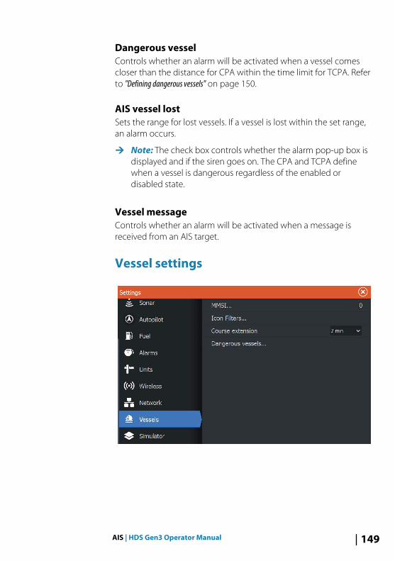
Dangerous vesselControls whether an alarm will be activated when a vessel comescloser than the distance for CPA within the time limit for TCPA. Referto "Defining dangerous vessels" on page 150.
AIS vessel lostSets the range for lost vessels. If a vessel is lost within the set range,an alarm occurs.
Ú Note: The check box controls whether the alarm pop-up box isdisplayed and if the siren goes on. The CPA and TCPA definewhen a vessel is dangerous regardless of the enabled ordisabled state.
Vessel messageControls whether an alarm will be activated when a message isreceived from an AIS target.
Vessel settings
AIS | HDS Gen3 Operator Manual 149

Your vessel’s MMSI numberYou need to have your own MMSI (Maritime Mobile Service Identity)number entered in the system to receive addressed messages fromAIS and DSC vessels.
It is also important to have the MMSI number entered to avoidseeing your own vessel as an AIS target on the chart.
Ú Note: The Vessel message option in the alarm settings must betoggled on for any MMSI message to be displayed.
Icon filtersBy default, all targets are shown on the panel if an AIS device isconnected to the system.
You can select not to show any targets, or to filter the icons basedon security settings, distance, and vessel speed.
Course extension linesYou can set the length of the Course Over Ground (COG) extensionlines for other AIS vessels. The length of the extension lines is eitherset as off, as a fixed distance, or to indicate the distance the vesselwill move in the selected time period. If Off is selected, then no COGextension lines are shown for the vessel. For information aboutextension lines for your vessel, refer to "Extension lines" on page 52.
Defining dangerous vesselsYou can define an invisible guard zone around your vessel. When atarget comes within the set limits, the symbol changes to theDangerous target symbol. An alarm is triggered if activated in theAlarm settings panel.
150 AIS | HDS Gen3 Operator Manual
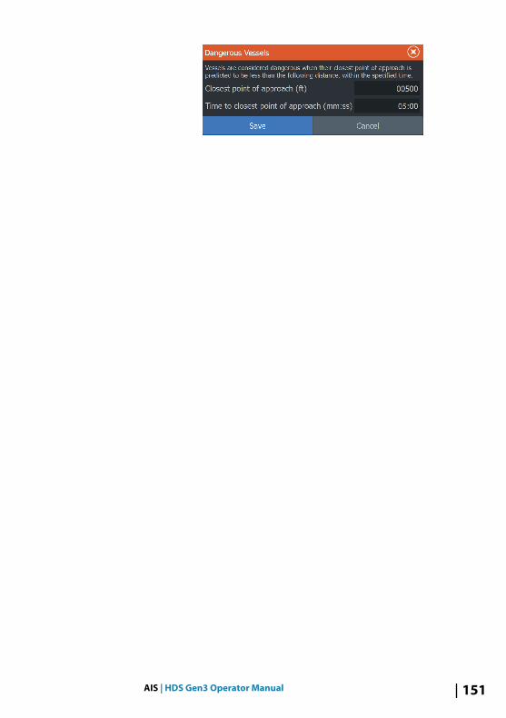
AIS | HDS Gen3 Operator Manual 151

AudioIf a SonicHub server, a FUSION marine entertainment system, orNMEA 2000 audio system is connected to the NMEA 2000 network,you can use the HDS Gen3 to control and customize the audiosystem on your vessel.
When connected to a WM-3 Satellite module with an activesubscription, you can include SiriusXM products on your system.You can also connect a SiriusXM radio to a FUSION system. Siriusaudio and weather service covers inland U.S. waters and coastalareas into the Atlantic and Pacific oceans, Gulf of Mexico, and theCaribbean Sea. The SiriusXM products received vary depending onyour selected subscription package. For more information refer towww.siriusXM.com.
Before you can start using your audio equipment, it must beinstalled according to the HDS Gen3 Installation manual and to thedocumentation included with the audio device.
Enabling audioA compatible audio device connected to the NMEA 2000 networkshould automatically be identified by the system. If not, enable thefeature from the Advanced Settings dialog.
Audio serverIf a SonicHub server and a FUSION system are connected to thesame network, one of the devices must be selected as the Audio
19
152 Audio | HDS Gen3 Operator Manual

server. If only one of the devices is present, it is the selected Audioserver by default.
SonicHub 2 A SonicHub 2 connected to the NMEA 2000 network is supported.
SonicHub 2 Device Information Open the Network Settings dialog and select the SonicHub 2 devicein the Device list. This opens the SonicHub 2 Device Informationdialog.
Audio | HDS Gen3 Operator Manual 153

ConfigureSelect to configure the device.
UpgradeUpdates the device software.
Ú Note: A USB memory stick with the software upgrade must beplugged into the device. Periodic software updates may beavailable from the product website. Detailed instructions forhow to install the software are included with the upgrade files.
Factory ResetResets the device to factory defaults.
SonicHub 2 is Bluetooth enabledThe SonicHub 2 is a Bluetooth enabled device. You can use theSonicHub 2's built-in Bluetooth wireless to connect it to Bluetoothenabled audio devices.
To pair the SonicHub 2 to a Bluetooth enabled device select theBluetooth devices option. Choose the Bluetooth device you want topair to from the list of available devices and then select Pair.
154 Audio | HDS Gen3 Operator Manual

The SonicHub 2 connects to the paired device.
Connecting and disconnecting paired devicesThe SonicHub 2 automatically connects to a device when you pairthem. You can pair it to several devices but only one device can beconnected at a time.
You can manually disconnect and connect the SonicHub 2 to paireddevices.
To disconnect a paired device, select the paired device in the devicelist and then select Disconnect.
To connect to a paired device, select the paired device in the devicelist and then select Connect.
Audio | HDS Gen3 Operator Manual 155

PandoraThe SonicHub 2 supports streaming music from Pandora from anAndroid device (over Bluetooth) or IOS device (over USB andBluetooth).
Ú Note: You must be in a valid location to use Pandora. Refer tothe Pandora website for more information.
Use menu controls to run Pandora on the smart device.
The Media bar When audio is enabled, the Media bar appears at the bottom of thescreen on all pages. The information in the Media bar variesdepending on the active audio source. Select the Media bar toreplace the application menus with Audio menus.
1 Media bar
2 Audio source
3 Track, file, or station information
4 Repeat - shown only when repeat is on
5 Shuffle - shown only when shuffle is on
6 Volume level
156 Audio | HDS Gen3 Operator Manual
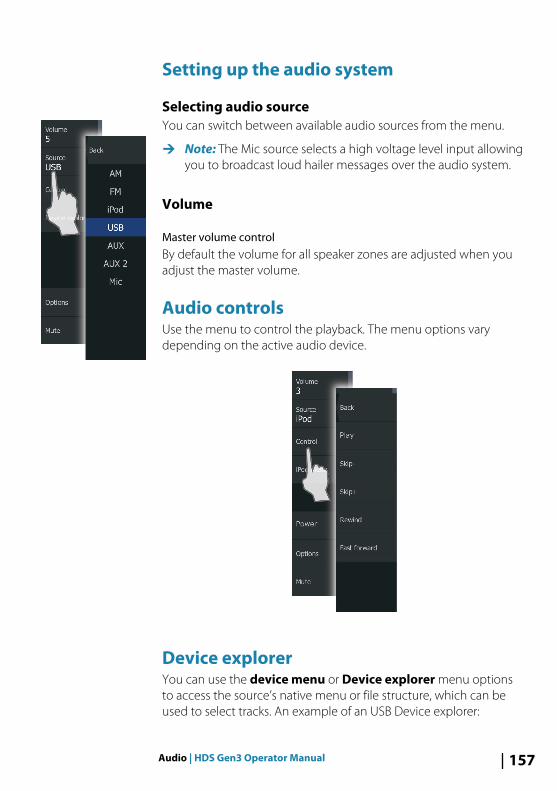
Setting up the audio system
Selecting audio sourceYou can switch between available audio sources from the menu.
Ú Note: The Mic source selects a high voltage level input allowingyou to broadcast loud hailer messages over the audio system.
Volume
Master volume controlBy default the volume for all speaker zones are adjusted when youadjust the master volume.
Audio controlsUse the menu to control the playback. The menu options varydepending on the active audio device.
Device explorerYou can use the device menu or Device explorer menu optionsto access the source’s native menu or file structure, which can beused to select tracks. An example of an USB Device explorer:
Audio | HDS Gen3 Operator Manual 157

Audio optionsUse the Options menu option to repeat or shuffle tracks or albums,and to open the Mixer. The options vary depending on the activeaudio device.
Audio mixerUse the Mixer to:
• Adjust the balance, volume, and volume limits individually foreach zone.
• Adjust the bass and treble, and the balance between zones.• Turn on or off individual speaker zones in the Master control.
The Mixer options vary depending on the activated audio device.The following is an example of the USB source mixer option for theAll Zones:
158 Audio | HDS Gen3 Operator Manual

Auxiliary sources AUX and AUX 2 (labeled AUX and SAT IN on the SonicHub) can beused for Sirius radio and external audio devices that support RCAconnectivity. Sirius radio playback can be controlled when aLowrance weather module is connected to SAT IN. Other auxiliaryaudio sources only have volume control.
Detaching Sirius from the AUX sourceIf a Sirius radio is connected to the FUSION radio/server, the AUXsource is automatically attached to the Sirius feed. Sirius thenappears in the source list when the FUSION server is active.
To use the AUX source for a different device, the Sirius must bedetached from the AUX source.
Ú Note: To use SiriusXM, an optional SiriusXM tuner must beconnected to the FUSION server.
Radio
Audio | HDS Gen3 Operator Manual 159

Selecting tuner regionBefore playing FM or AM radio, and using a VHF radio, you mustselect the appropriate region for your location.
Radio favoritesWhen a channel is tuned in, you can add the station to the favorite’slist. All favorite channels can be viewed, selected, and deleted fromthe Favorites dialog.
160 Audio | HDS Gen3 Operator Manual

Sirius radio (North America only)
Channels listThe channels list displays all available Sirius channels, whether ornot you have a subscription for the channel.
Favorites listYou can create a list of your favorite Sirius channels from within thechannels list. You cannot add unsubscribed channels.
Locking channelsYou can lock selected Sirius channels from being broadcasted. A 4-digit-code must be entered to lock channels and the same codeentered to unlock the channels.
DVD videoYou can view DVD video from a FUSION-Link device on units with aVideo Adapter cable (000-11010-001), sold separately.
Controlling DVD video1. Insert a DVD into the device.2. Open the Home page and select the Video page.3. Activate the Audio panel and select DVD as the source on the
menu.4. Select the Control menu option.5. Use the menu options to control the playback.
Audio | HDS Gen3 Operator Manual 161

SiriusXM weatherWhen connected to a Navico Weather module, you can subscribeand include Sirius audio and Sirius Marine Weather Service on yoursystem (North America only).
Depending on your selected subscription package, Sirius audio andweather service covers a variety of North American inland watersand coastal areas. For more information refer to www.siriusxm.com/marineweather
Sirius status panelWhen the weather module is connected to the system, you getaccess to the Sirius status panel.
The status panel shows signal strength is indicated as 1/3 (weak),2/3 (good) or 3/3 (preferred). It also includes antenna status, servicelevel, and the electronic serial number for the weather module.
Sirius weather displaySirius weather can be displayed as an overlay on your chart panel.
When weather overlay is selected, the chart menu increases toshow the available weather options.
20
162 SiriusXM weather | HDS Gen3 Operator Manual

1 Precipitation color shading
2 City forecast icon
3 Wind barb
4 Storm icon
5 SST color bar
6 SST color shading
Use the Sirius weather option menu to select which weathersymbology that should be displayed and how they should appearon the chart panel.
Wind barbsThe rotation of the wind barbs indicate the relative wind direction,with the tail showing the direction the wind is coming from. In thegraphics below, the wind comes from the northwest.
Wind speed is indicated by a combination of small and large barbsat the end of the wind tail.
Zero knots / Indeterminate wind direction
Small barb = 5 knots
Large barb = 10 knots
SiriusXM weather | HDS Gen3 Operator Manual 163

Arrow barb = 50 knots
If a combination of 5 and 10 knot barbs are shown on a tail, thenadd them together to give you the total wind speed. The examplebelow shows 3 x large barb + 1 x small barb = 35 knots, and 60knots indicated with 1 x arrow barb + 1 x large barb.
Wind speed: 35 knots Wind speed: 60 knots
Showing weather detailsIf pop-up is enabled, you can select a weather icon to display theidentity of the observation. If you select the pop-up, detailedinformation about the observation is displayed. You can also displaythe detailed information from the menu when the weather icon isselected.
Sirius view options
PrecipitationShades of color are used to show precipitation type and intensity.The darkest color indicates the highest intensity.
Rain From light green (light rain) - yellow - orange - todark red (heavy rain)
Snow Blue
Mixed Pink
Sea Surface Temperature (SST)You can show the sea surface temperature as color shading or astext.
When color coding is selected, the SST color bar is shown on the leftside of the display.
164 SiriusXM weather | HDS Gen3 Operator Manual

You define how the color codes are used to identify sea surfacetemperature. See "Adjusting color codes" on page 167.
Wave indicationColors are used to indicate forecasted wave height. The highestwaves are dark red, while the lowest are blue.
You can define how the color codes are used to identify the waveheight. Refer to "Adjusting color codes" on page 167.
Surface featuresTurns surface features on/off. Surface features include fronts, isobars,and pressure points. Surface features cannot be shown at the sametime as Wind.
Cloud topsTurn Cloud tops on/off. Cloud tops indicate the height of the top ofthe clouds. The color palette used is grey with darker greysindicating lower clouds. Cloud tops cannot be shown at the sametime as Precipitation or Echo Tops.
Ú Note: This feature is only available for certain SiriusXMsubscriptions.
Echo topsTurns Echo tops on/off. Echo tops indicate the tops of storms. Thecolor palette used is the same as for Precipitation. Echo tops cannotbe shown at the same time as Precipitation or Cloud Tops.
Ú Note: This feature is only available for certain SiriusXMsubscriptions.
Weather iconsSeveral weather icons are available to show current or predictedweather conditions. You can select an icon to display detailedweather information.
City forecast
Surface observation
SiriusXM weather | HDS Gen3 Operator Manual 165

Tropical storm tracking; past (grey) - present (red) -future (yellow)
Hurricane (category 1-5) tracking; past (grey) -present (red) - future (yellow)
Tropical disturbance/depression tracking; past (grey)- present (red) - future (yellow)
Storm attributes
Lightning
Watch box location and warning
Marine zone location
Local weatherSelect the Local weather menu option to display the Local weatherdialog. This dialog shows weather forecast and alerts for the area.
Select a time-slot tab to see the forecast for it.
Marine zonesDepending on your selected subscription, SiriusXM servicesincludes access to weather reports for U.S. and Canadian MarineZones, with the exception of the high seas zones.
166 SiriusXM weather | HDS Gen3 Operator Manual

You can select a marine zone on a chart and view its forecast. Youcan also select a marine zone as your current zone of interest andyou will be notified of any weather warnings in that zone.
Tropical statementsYou can read tropical statements including information abouttropical weather conditions. These statements are available for theentire Atlantic and the Eastern Pacific.
Adjusting color codesYou can define the sea surface temperature range and wave heightcolor coding.
The temperature above warm and below cool values is displayed asprogressively darker red and darker blue.
Waves higher than the maximum value are indicated withprogressively darker red. Waves lower than the minimum value arenot color coded.
Animating Sirius weather graphicsThe HDS Gen3 records the weather information you have turned on,and this information can be used to animate past or future weatherconditions. The amount of information available in the systemdepends on the amount of weather activity; the more complex it is,the less time that is available for animation.
You can animate the past or the future, depending on whichweather view you have turned on:
• With precipitation overlay, you can animate for the past and onlyassume weather conditions in the immediate future.
• With colored wave height overlay, you can animate the future(the predictions).
When activated, the time for the current graphic animation isdisplayed in the lower left corner of the chart panel.
Weather alarmsYou can setup lightning or storm alarms to occur when theconditions are within a certain range of your vessel.
You can also set up an alarm as a severe weather forecast alarmissued for your chosen marine zone.
SiriusXM weather | HDS Gen3 Operator Manual 167

A watchbox is defined by the National Weather Service. When thealarm for watchbox is turned on, an alarm occurs when your vesselis entering or inside a watchbox.
168 SiriusXM weather | HDS Gen3 Operator Manual

ToolsBy default, the Tools panel includes icons used for accessing optionsand tools that are not specific to any panel.
When external equipment is integrated to the unit, new icons mightbe added to the Tools panel. These icons are used for accessing theexternal equipment's features.
Waypoints/routes/trailsList of waypoints, routes, and trails with details.
Select the waypoint, route, or trail you want to edit or delete.
TidesDisplays tide information for the tide station nearest to your vessel.
Select the arrow panel buttons to change the date, or select thedate field to access the calendar function.
Available tide stations can be selected from the menu.
Alarms
Active alarmsList of active alarms.
Alarm historyList of all alarms with time stamp.
Alarm settingsList of all available alarm options in the system, with currentsettings.
SettingsProvides access to application and system settings.
System settingsThe system settings provides access to the following:
LanguageControls the language used on this unit for panels, menus, anddialogs. Changing the language causes the unit to restart.
21
Tools | HDS Gen3 Operator Manual 169

Text sizeUsed for setting the text size in menus and dialogs.
Default setting: Normal
Key beepsControls the loudness of the beep sound when a key is pressed.
Default setting: Loud
TimeControls the local time zone offset, and the format of the time anddate.
DatumMost paper charts are made in the WGS84 format, which also isused by the HDS Gen3.
If your paper charts are in a different format, you can change thedatum settings accordingly to match your paper charts.
Coordinate systemSeveral coordinate systems can be used to control the format forlatitude and longitude coordinates displayed on the chart panel.
Magnetic variationMagnetic variation is the difference between true bearings andmagnetic bearings, caused by different locations of the Geographicand the Magnetic north poles. Any local anomalies such as irondeposits might also affect the magnetic bearings.
When set to Auto, the system automatically converts magneticnorth to true north. Select manual mode if you need to enter yourown local magnetic variation.
SatellitesStatus page for active satellites.
WAAS (and EGNOS) differential position correction can beconfigured to ON or OFF.
Restore defaultsAllows you to select which settings are to be restored to theiroriginal factory settings.
170 Tools | HDS Gen3 Operator Manual

Warning: If waypoints, routes, and trails are selected,they are permanently deleted.
AdvancedShows a panel with more advanced settings. Used for setting howyour system displays various user interface information. In addition,controls which features are shown in the interface.
AboutDisplays copyright information, software version, and technicalinformation for this unit.
The Support option accesses the Network analyzer and serviceassistant, refer to "Network analyzer and service assistant" on page 179.
NavigationProvides options and dialogs where you specify settings for yournavigation, such as arrival radius, XTE limit, XTE Alarm, Trails, andLogging Type. Refer to "Navigation settings" on page 66.
ChartProvides options and dialogs where you specify settings for yourcharts. Settings and display options made in the Chart settings pageare common for all chart panels. Refer to "Chart settings" on page 51.
SonarProvides options and dialogs where you specify settings for yoursonar. Refer to "Sonar settings" on page 78.
RadarProvides options and dialogs where you specify settings for yourradar. Refer to "Radar settings" on page 142.
AutopilotProvides options where you specify settings for your autopilot. Referto "Autopilot settings" on page 109.
Tools | HDS Gen3 Operator Manual 171

FuelProvides a dialog showing total fuel used, fuel used per trip, and fuelused per season. In addition, it provides access to configurationengine and tanks, and calibration of tanks (refuel) dialogs. Refer tothe Installation Manual.
AlarmsProvides the option to enable the siren. It also provides a dialogwhere you specify turning on alarms for items, and includes activealarm information and alarm history.
UnitsProvides setup of units of measure used on various data types.
WirelessProvides dialogs where you set remote controllers, view wirelessdevices, and customize advanced settings. For more informationabout using this panel, refer to "Wireless settings" on page 127.
NetworkProvides information about your network, settings options, andconfiguration options. For more information about using this panel,refer to the Installation Manual.
VesselsProvides dialogs where you define your vessel's MMSI, set iconfilters, set course extension length, and specify dangerous vesselssettings of closest point of approach and time to closest point ofapproach. For more information about using this panel, refer to"Vessel settings" on page 149.
SimulatorProvides for manually controlling the simulator. For moreinformation, refer to "Simulator" on page 102.
172 Tools | HDS Gen3 Operator Manual

Vessels
Status listingList of all AIS, MARPA, and DSC vessels with available information.
Message listingList of all messages received from other AIS vessels with time stamp.
Sun, MoonDisplays sunrise, sunset, moonrise and moonset for a position basedon entered date and the position’s latitude/longitude.
Trip calculator
Trip 1 / Trip 2Displays voyage and engine information, with reset option for alldata fields.
TodayDisplays voyage and engine information for current date. All datafields are automatically reset when the date changes.
FilesFile management system, used to browse the contents of the unit'sinternal memory and inserted SD card.
Viewing filesSelect a file in the Files panel and then the view file option in theDetails dialog.
Copying files to a card in the card readerYou can copy screen captures and logs to a card in the card reader.You can also export System Settings, Waypoints, Routes, and Trailsto a card. Exporting files is covered in the section "Maintenance" onpage 178.
FindSearch function for chart items (waypoints, routes, trails, etc.).
Tools | HDS Gen3 Operator Manual 173

GoFree ShopÚ Note: The built-in wireless functionality must be connected to
an external wireless hotspot in order to access the GoFree Shop.Refer to "Connect and disconnect from a wireless hotspot" on page 123.
Opens the GoFree Shop web site. At the GoFree Shop you canbrowse, purchase, and download compatible charts for your system.You can also upload your Sonar logs to be shared on Social Mapcharts. When you log on, the system automatically gives you anotification if a new software version is available for your system. Ifan update is available, you can download it to a card slot or deferthe download until later.
174 Tools | HDS Gen3 Operator Manual

Alarms
Alarm systemThe system continuously checks for dangerous situations andsystem faults while the system is running. When an alarm situationoccurs, an alarm message pops up on the screen.
If you have enabled the siren, the alarm message is followed by anaudible alarm, and the switch for external alarm becomes active.
The alarm is recorded in the alarm listing so that you can see thedetails and take the appropriate corrective action.
Type of messagesThe messages are classified according to how the reported situationaffects your vessel. The following color codes are used:
Color Importance
Red Critical
Orange Important
Yellow Standard
Blue Warning
Green Light warning
Single alarmsA single alarm is displayed with the name of the alarm as the title,and with details for the alarm.
Multiple alarmsIf more than one alarm is activated simultaneously, then the alarmmessage displays a list of up to 3 alarms. The alarms are listed in theorder they occur with the alarm activated first at the top. Theremaining alarms are available in the Alarms dialog.
22
Alarms | HDS Gen3 Operator Manual 175

Acknowledging a messageThe following options are available in the alarm dialog foracknowledging a message:
• CloseSets the alarm state to acknowledged, meaning that you areaware of the alarm condition. The siren / buzzer stops and thealarm dialog is removed.However, the alarm remains active in the alarm listing until thereason for the alarm has been removed.
• DisableDisables the current alarm setting. The alarm does not showagain unless you turn it back on in the Alarms dialog.
There is no time-out on the alarm message or siren. They remainuntil you acknowledge the alarm or until the reason for the alarm isremoved.
Alarms dialogAll alarms are setup in the Alarms Settings dialog.
The alarm dialogs can also be activated from the Tools panel. Thealarm dialogs include information about active alarms and alarmhistory.
176 Alarms | HDS Gen3 Operator Manual

Alarms | HDS Gen3 Operator Manual 177

Maintenance
Preventive maintenanceThe unit does not contain any field serviceable components.Therefore, the operator is required to perform only a very limitedamount of preventative maintenance.
It is recommended that you always fit the supplied protective suncover when the unit is not in use.
Checking the connectorsThe connectors should be checked by visual inspection only.
Push the connector plugs into the connector. If the connector plugsare equipped with a lock, ensure that it is in the correct position.
Touchscreen calibrationÚ Note: Ensure the screen is clean and dry before doing the
calibration. Do not touch the screen unless prompted to do so.
In some cases it may be required to re-calibrate the touch screen. Tore-calibrate your touchscreen, do the following:
1. Turn the unit off2. Press and hold the Waypoint key, and turn the unit on3. Continue to press in the Waypoint key during power on, until
the calibration utility screen comes up4. Follow the instructions on the screen to perform the calibration.
When completed, the unit returns to the application screen.
NMEA Data loggingAll serial output sentences sent over the NMEA TCP connection arelogged to an internal file. You can export and review this file forservice and fault finding purposes.
The maximum file size is predefined. If you have added several otherfiles to the system (file recordings, music, pictures, PDF files), thismay reduce the allowed file size for the log file.
The system logs as much data as possible within the file sizelimitation, and then it starts overwriting the oldest data.
23
178 Maintenance | HDS Gen3 Operator Manual

Exporting the log fileThe log file can be exported from the files dialog.
When you select the Log database you are prompted to select adestination folder and filename. Once accepted, the log file iswritten to the chosen location.
Software upgradesThe latest software is available for download from our website,www.lowrance.com.
Before initiating an update to the unit itself, be sure to back up anypotentially valuable user data. Refer to "Backing up your system data" onpage 181.
The system or the Network analyzer and service assistant can advisesoftware updates are available.
Network analyzer and service assistantThe system has a built-in service assistant that creates a report ofthe devices installed on the NMEA 2000 and Ethernet network suchas the software versions, serial numbers, and information from thesettings file to assist in technical support enquiries.
To use the analyzer, open the About page of the System settingsdialog and select Support. Two options are displayed:
Create report
Maintenance | HDS Gen3 Operator Manual 179

Analyzes your network and prompts you for information requiredfor support and creates the report with information automaticallygathered from the network. You can add screenshots and log filesthat will be attached to the report. There is a 20MB limit for thereport attachments. You can save the report to a memory card andemail it to support or upload it directly if you have an internetconnection. If you call technical support first, you can enter anincident number to assist with tracking.
Check system for updatesAnalyzes your network and checks if updates are available forcompatible devices.
Ú Note: Connect your unit to the internet to check for the latestavailable software versions. The software versions will be up todate as of the last time you updated your unit or connected tothe internet.
Update software
Ú Note: Remove any mapping cards from your unit and install amemory card with sufficient storage before downloadingsoftware updates or creating and saving reports to the memorycard.
Ú Note: Do not turn off the MFD or device until the update iscompleted or you are prompted to restart the unit or devicebeing updated.
1. If your MFD is connected to the Internet, you can download thesoftware update from the Updates Dialog into a memory card.You can also download the software update fromwww.lowrance.com to a memory card inserted in a smartdevice or PC connected to the internet.
2. Insert the card containing the software updates in your MFD.3. Select the item to be updated in the Updates Dialog and
follow the prompts.
As you respond to the prompts the update occurs. Prompts mayrequest that you restart the device to complete the update. You canrestart devices to complete the update later at a more convenienttime.
180 Maintenance | HDS Gen3 Operator Manual

Backing up your system dataWaypoints, Routes, and Trails that you create are filed in yoursystem. It is recommended to regularly copy these files and yoursystem settings files as part of your back-up routine. The files can becopied to a card inserted in the card reader.
There are no export file format options for the system settings file.The following output formats are available for exporting Waypoints,Routes, and Trails files:
• User Data File version 5This is used to import and export waypoints and routes with astandardized universally unique identifier (UUID), which is veryreliable and easy to use. The data includes such information asthe time and date when a route was created.
• User Data File version 4This is best used when transferring data from one system toanother, since it contains all the extra bits of information thesesystems store about items.
• User Data file version 3 (w/depth)Should be used when transferring user data from one system to alegacy product (Lowrance LMS, LCX)
• User data file version 2 (no depth)Can be used when transferring user data from one system to alegacy product (Lowrance LMS, LCX)
• GPX (GPS Exchange, no depth)This is the format most used on the web that shares among mostGPS systems in the world. Use this format if you are taking data toa competitor's unit.
Export all Waypoints, Routes and TrailsUse the export option if you want to backup all Waypoints, Routes,and Trails on your system.
Maintenance | HDS Gen3 Operator Manual 181

Export regionThe export region option allows you to select the area from whereyou want to export data.
1. Select Export region2. Drag the boundary box to define the desired region
3. Select the export option from the menu4. Select the appropriate file format5. Select the serial port field to start the export
182 Maintenance | HDS Gen3 Operator Manual

Purging Waypoints, Routes and TrailsDeleted Waypoints, Routes and Trails are stored in the display unit'smemory until the data is purged. This is necessary to allow user datato be synchronized across multiple units on an Ethernet network. Ifyou have numerous deleted, unpurged Waypoints, purging mayimprove the performance of your system.
Ú Note: When user data is purged from the memory, it cannot berecovered.
Maintenance | HDS Gen3 Operator Manual 183

Touchscreen operationBasic touchscreen operation on the different panels is shown in thetable below.
The panel sections in this manual have more information aboutpanel specific touchscreen operation.
Icon Description
Tap to:• Activate a panel on a multi-panel page• Position the cursor on a panel• Select a menu and a dialog item• Toggle a checkbox option on or off• Show basic information for a selected item
Press and hold:• On any panel with a cursor to activate the cursor
assist feature• On a panel button to see available split screen
options• On a favorite button to enter edit mode
Scroll through a list of available options withoutactivating any option.
Flick to quickly scroll through e.g. the waypoint list.Tap the screen to stop the scrolling.
Pan to position a chart or Sonar image on thepanel.
24
184 Touchscreen operation | HDS Gen3 Operator Manual

Icon Description
Pinch to zoom out on the chart or on an image.
Spread to zoom in on the chart or on an image.
Touchscreen operation | HDS Gen3 Operator Manual 185

186 Touchscreen operation | HDS Gen3 Operator Manual

IndexA
About this unit 171Active panel 28Adjusting panel size 31Advanced settings
SpotlightScan 90Advanced systemsettings 171AIS 144
Calling a vessel 146Course extension lines 150DSC 146Icon filters 150Information on radarpanels 146Searching for AISitems 145Target symbols 144Viewing information abouttargets 145
AIS SART 147Alarm message 147
AlarmsAcknowledging 176Alarm settings dialog 176Multiple alarms 175Single alarm 175Type of messages 175
Amplitude scope 77Anchor mode 106App
GoFree Link 124Application pages 19Arrival
Mode 110Arrival mode
Autopilot 106Arrival radius 66Audio 152
Auxiliary 159Controls 157Detaching Sirius 159Device explorer 157Device menu 157DVD video 161Enable 152Master volume control 157Mixer 158Options 158Radio 159Radio favorites 160Selecting audio source 157Selecting tuner region 160Server selection 152Setting up the system 157Sirius radio 161
Auto sensitivitySonar 71
AutopilotAnchor mode 106Anchor point setup 110Arrival mode 106, 110Chart compass 110, 121Control locationsetting 110, 121Control of the trollingmotor 106Controller 105Depth contourtracking 115Heading Lock mode 106Information bar 105information bar, hide 110,122Interface 105Nav. mode 108Outboard 112Power steer mode 113Settings 121
Index | HDS Gen3 Operator Manual 187

Settings, trollingmotor 109Speed control 108Standby mode 106Start automaticnavigating 119Trolling motor 104Turn off automaticnavigation 104Turn pattern steering,Outboard motor 114Turn pattern steering,Trolling motor 107Waypoint arrival circle 118
Autorouting, see Dock-to-dock Autorouting 59Autorouting
Dock-to-dock 59Auxiliary, audio sources 159
B
Backing up your systemdata 181Bluetooth
Enable 129Pairing devices 126Wireless technology 126
Bottom lock 76
C
C-MAP chart options 42Card
Copying files to 173Charts
Symbol 37Charts 34
3D charts 39C-MAP chart options 40Chart compass 110, 121Chart data 35
Chart panel 34Chart scale 36Course up 37Creating routes 38Dual charts 35Embedded cartography 35Find chart objects 39Heading up 37Insight chart options 40Look ahead 37Measuring distance 29Navionics chart options 46North up 37Orientation 37Overlay 40Panning 36Positioning the vessel on thechart panel 37Radar overlay source 131Selecting chart type 36Settings 51Using the cursor 38Vessel symbol 36Zooming 36
ColorlineAdjusting 71Sonar 71
Configuring overlay data 32Connect
Bluetooth devices 126Smartphone andtablet 124Wireless hotspot 123
Contrast, SpotlightScan 91Control location setting,Autopilot 110, 121Controller and viewer app
GoFree Link 124Converting trails to routes 58Coordinate system 170Copying files to a card 173
188 Index | HDS Gen3 Operator Manual

Cursor 28Cursor assist 28Customizing your system 31CZone 22
D
Dangerous vessels 150Dashboards 99Data Overlay 32Datum 170DCT 115Demo mode 102Depth line 77Dialog boxes 27Disconnect
Wireless hotspot 123Display illumination 26Dock-to-dock Autorouting
Entire route 59, 60Example 60Selection 60
DVD video 161
E
Easy Routing 59Example 60
EBL/VRM markers 137Export region 182
F
Favorite pages 20Adding new 32Edit 33
Features, how to turn on 171Files to a card, copying 173Files, management 173Files
Viewing 173Find items tool 173
Fishing mode 79Reset 80
Flasher 77Frequency 70Frequency, SpotlightScan 90Front panel 16Fuel 172FUSION-Link 21, 152
G
Go to cursor 28GoFree
Shop 124Wireless connection 123
GoFreeLink 124Smartphoneconnection 125Tablet connection 124
H
Heading Lock mode 106Heading Sensor
Configure for trollingmotor 89
Home page 18Home page background 31
I
Illumination 26Image
Trolling motoralignment 90
Improving systemperformance 183Info panels 99Insight chart options 42Integration of 3rd partydevices 21
Index | HDS Gen3 Operator Manual 189

Internet usage 5
K
Key beeps 170Keys 16
L
Language 169Locking the touchscreen 26Log sonar 80Log sonar data 87Logging type, Navigatingsettings 67Look Ahead
SpotlightScan 91
M
Magnetic variation 170Maintenance
TouchscreenCalibration 178
Man OverboardCancel navigation toMOB 30Creating a MOB 29Display information 30
Manual modeSonar 73
ManualAbout 5Version 6
Manuals, viewing 6Measuring distance 29Media bar 156MMSI number 150
N
Nav. mode 108Navigate 63
Arrival radius 66Datum 170Logging type 67Routes 64Steer panel 64To cursor position 64Trails 66With autopilot 65XTE alarm 66
Navigation settings 66Navionics chart options 46Network
Settings 172NMEA Data logging 178NMEA
Exporting log file 179Noise rejection 72
O
Operating the system 15Operation
SpotlightScan tips 91Touch 184
Options, SpotlightScan 90Overlay data
Configuring 32turn on and off 32
Overlay downscan 79Overlay, data information 32
P
PagesSelecting a page 27Selecting active panel 28
PairBluetooth devices 126
Palettes 77, 85, 91Panels
Adjusting panel size 31PDF, viewing files 6
190 Index | HDS Gen3 Operator Manual

Phantom Loran 67Settings 67
Ping speed 72Power-Poles 22
Controls 22Dual, pairing with 127
PPI 136Preventive maintenance 178Preview history
Sonar 77Purging 183
Q
Quick split pages 20
R
Radar 130Alarm settings 139, 141Course up 135EBL/VRM markers 137EBL/VRM
Placing 137EBL/VRMFast scan 134Gain 132Guard zone 138Heading up 135Interference 134MARPA
Target symbols 139Targets 139Tracking targets 140View target info 140
North up 135Offset 136, 138Operational modes 131Orientation 135Overlay 131Palette 135Position radar center 136
PPI 136Radar overlay source 131Radar panel 130Rain clutter 133Range 132Recording data 141Sea clutter 133Sea State 134Sensitivity 139Settings 142Target boost 134Target expansion 134Target trails 135Threshold 133
Radio, as an audiodevice 159Range 70
SpotlightScan 90Recording
Start recording log data 73Start recording sonardata 73
Reset fishing mode 80Restore defaults 170Routes 57
Creating a new route on thechart panel 57Creating a route fromexisting waypoints 58Delete 58Dialog 54Dock-to-dockAutorouting 59Easy Routing 59Edit in chart panel 57Edit Route dialog 61Navigate 64
Index | HDS Gen3 Operator Manual 191

S
Satellites, systemsettings 170Saving waypoints 55Screen capture 30Scroll speed 72Sea State 134Sensitivity
Adjusting 71Sonar 71
SettingsAutopilot 121Autopilot, trollingmotor 109Network 172SpotlightScan 89Tools 169Unit of measure 172
Simulator 102Demo mode 102Source files 102
Sirius radio 161Channels list 161Favorite list 161Locking channels 161
Sirius weatherAnimated weathergraphics 167Color codes 167Marine zones 166Overlay on chart panel 162Precipitation 164Sea Surface Temperature(SST) 164Status panel 162Tropical statements 167Wave indication 165Weather icons 165
SiriusXM weather 162SL2 format 73
SL3 format 73SLG format 73SmartCraft VesselView 21Smartphone connection 125Software upgrade 179Software version 7Software
How to update 180Sonar 68
Auto sensitivity 71Colorline 71Fish ID 78Image 68Manual mode 73Menu 70Ping speed 72Preview history 77Scroll speed 72Sensitivity 71Split screen 76Split Zoom 76Start recording sonardata 73Stop recording log data 74Stop sonar 72Surface clarity 72Using the cursor 69View history 70View options 76View recorded data 75Zoom bar 69Zooming 69
SonicHub 152Speed control, Trollingmotor 108Split pages 19Split screen
Sonar 76SpotlightScan 88
Advanced settings 90
192 Index | HDS Gen3 Operator Manual

Configure headingsensor 89Contrast 91Display SpotlightScanimages 89Frequency 90Image 88Image and trolling motoralignment 90Look Ahead 91Operation tips 91Options 90Range 90Setup 89Stop sonar 91View 91
Standby mode,Autopilot 106Steer panel 64Stop sonar 72
SpotlightScan 91StructureMap 74, 93
Activate 93Image 93Live source 94Mapping cards 96Options 97Saved files 94Sources 94Tips 95
StructureScan 82Advanced settings 86Auto range 85Contrast 85Convert data toStructureMap format 95Flipping the image 86Frequencies 85Image 82Noise rejection 86Preset range levels 85
Preview 86Range 85Range lines 86Recording data 95Surface clarity 86Using the cursor 83View down or side scan 85View history 84View options 82Zooming 83
Surface claritySonar 72
System Controls dialog 25System Settings 169
About copyright and thisunit 171Advanced 171Coordinate system 170Datum 170Key beeps 170Language 169Magnetic variation 170Restore defaults 170Satellites 170Text size 170Time 170
T
Tablet connectionGoFree, wireless 124
Temperature graph 77Text size 170Time 170Tools 169Tools
Find items 173Routs 169Settings 169Trails 169Waypoints 169
Index | HDS Gen3 Operator Manual 193

Touchscreen Calibration 178Touch
Operation 184Touchscreen
Locking 26Trails
Converting trails toroutes 58Creating new 62Dialog 54Navigating settings 66Settings 62
Trolling motorAutopilot control 106Configure headingsensor 89Image alignment 90Speed control 108
Turn off automaticnavigation 104Turn pattern steering
Outboard autopilot 114Trolling autopilot 107
Turning the unit on andoff 25
U
UnitChecking theconnectors 178
Units of measure,setting 172Update software 180
V
Vessel alarms 148Vessel settings 149Video 101
Adjusting the image 101Setting up the panel 101
Source 101Standard 101
VideoVideo panel 101
View Sonar log 80Viewing files 173View
SpotlightScan 91
W
Wallpaper, customizing 31Warranty 4Waypoints, routes and trails
Export 181Purging 183
Waypoints 54Alarm settings 57Delete 56Dialog 54Edit 56Moving 56Saving 55
WeatherAlarms 167Showing weatherdetails 164
Wind barbs 163Wireless hotspot
Connect anddisconnect 123
WirelessDevices details 128Smartphoneconnection 125Tablet connection 124
X
XTE alarmNavigating settings 66
XTE limit 66
194 Index | HDS Gen3 Operator Manual

xtf format 73
Z
ZoomSonar 76
Index | HDS Gen3 Operator Manual 195

*988
-107
40-0
05*
0980


