Date post: | 03-Jun-2018 |
Category: |
Documents |
Upload: | bui-xuan-duc |
View: | 220 times |
Download: | 0 times |
8/12/2019 he thong nap tren o to
http://slidepdf.com/reader/full/he-thong-nap-tren-o-to 1/26
Electrical Circuit Diagnosis - Course 623 5-1
The charging system has two essential functions:
• Generate electrical power to run the vehicle’s electrical systems
• Generate current to recharge the vehicle’s battery
Electrical power − At low engine speeds, the battery may supplysome of the power the vehicle needs. At high engine speeds, thecharging system handles all of the vehicle’s electrical requirements.
Charging − Alternator (generator) output is higher than batteryvoltage to recharge the battery.
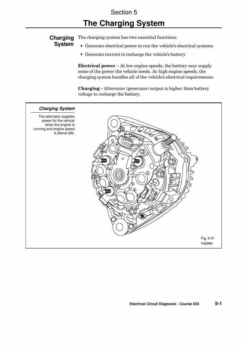
Charging System
The alternator supplies
power for the vehiclewhen the engine isrunning and engine speed
is above idle.
Fig. 5-01TL623f501
Section 5
The Charging System
ChargingSystem
8/12/2019 he thong nap tren o to
http://slidepdf.com/reader/full/he-thong-nap-tren-o-to 2/26
Section 5
5-2 TOYOTA Technical Training
These components make up the charging system:
• Alternator
• Voltage regulator
• Battery
• Charging indicator
Charging System Components
This figure shows themajor components of the
charging system.
Fig. 5-02TL623f500
Charging SystemComponents
8/12/2019 he thong nap tren o to
http://slidepdf.com/reader/full/he-thong-nap-tren-o-to 4/26
Section 5
5-4 TOYOTA Technical Training
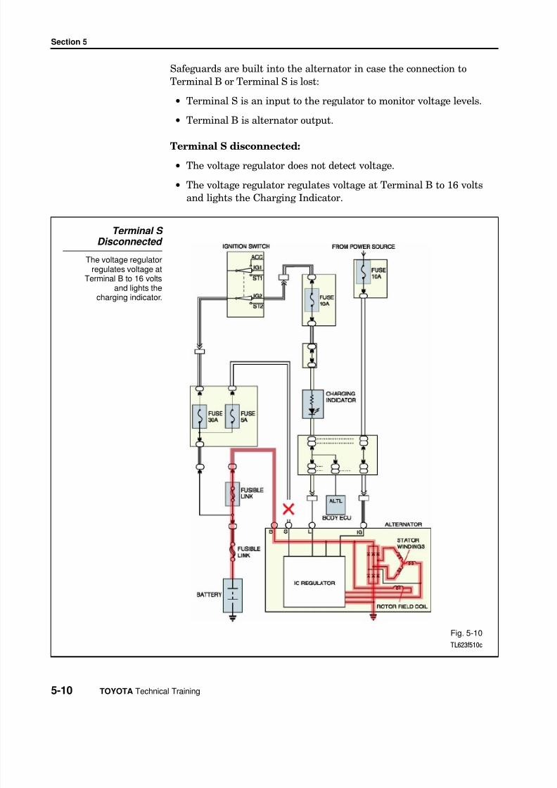
The voltage regulator controls the alternator’s output current to preventover−charging and under−charging of the battery. It does this byregulating the current flowing from the battery to the rotor’s field coil.
Today’s IC voltage regulator is a fully electronic device, using resistors
and diodes.
Voltage Regulator
The voltage regulatorcontrols the alternator’s
output current.
Fig. 5-04TL623f504
Voltage Regulator
8/12/2019 he thong nap tren o to
http://slidepdf.com/reader/full/he-thong-nap-tren-o-to 5/26
The Charging System
Electrical Circuit Diagnosis - Course 623 5-5
The battery supplies current to energize the alternator field coil. Thebattery also acts as a voltage stabilizer. The battery must alwaysremain attached to the electrical system while the engine is running.
Battery
The battery suppliescurrent to energize the
alternator’s field coil.
Fig. 5-05TL623f505
Battery
8/12/2019 he thong nap tren o to
http://slidepdf.com/reader/full/he-thong-nap-tren-o-to 6/26
Section 5
5-6 TOYOTA Technical Training
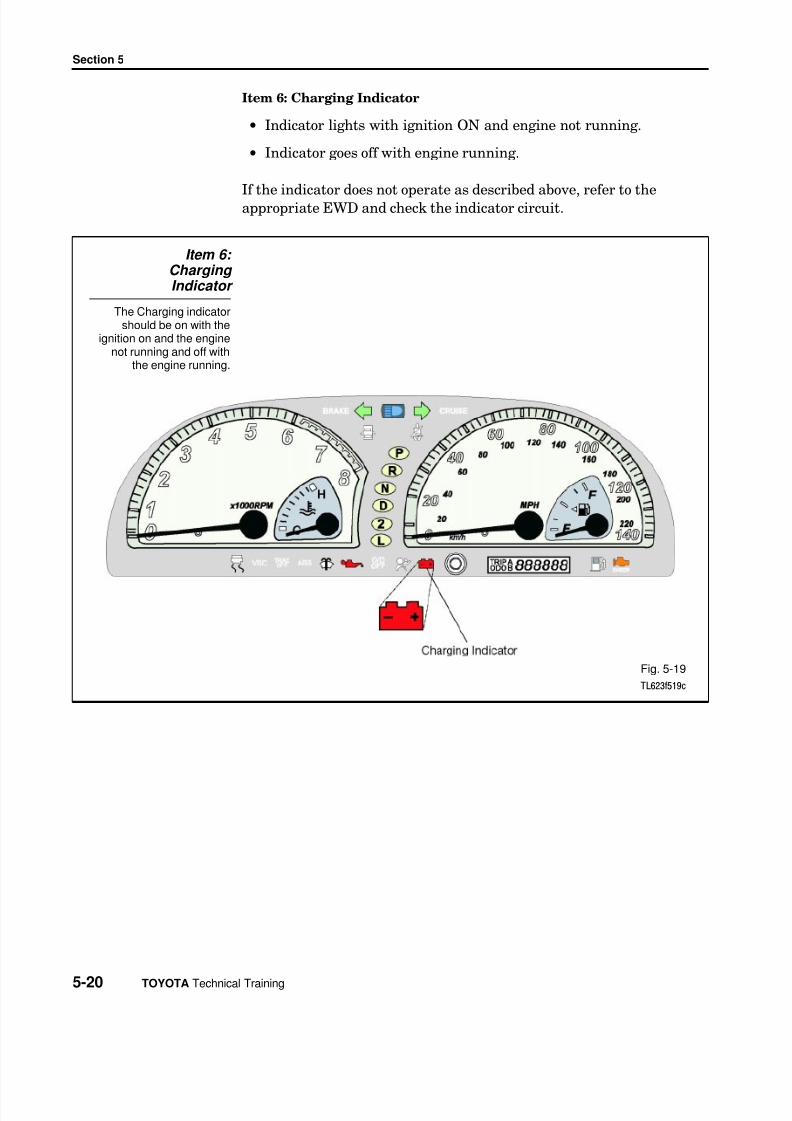
The charging indicator is usually an ON/OFF warning lamp. When thesystem is running, the light should be OFF. The lamp lights when thecharging system is not providing sufficient charge.
Charging Indicator
The charging indicatorlights when the chargingsystem is not supplying
enough power to chargethe battery.
Fig. 5-06TL623f506c
Charging Indicator
8/12/2019 he thong nap tren o to
http://slidepdf.com/reader/full/he-thong-nap-tren-o-to 7/26
The Charging System
Electrical Circuit Diagnosis - Course 623 5-7
Current in the charging system changes for these three differentoperating conditions:
• Ignition switch to ON − engine stopped• Ignition switch to ON − engine running alternator output below
desired voltage• Ignition switch to ON − engine running alternator output above
desired voltage
Ignition switch to ON − engine stopped:
• As soon as the ignition switch is turned to ON, the IC regulatorcauses a current of about 0.2 amps through the rotor’s field coil.
• The IC regulator turns on the charging indicator.• There is no output from the stator because the rotor is not turning.
Ignition Switch to ON - Engine Stopped
The IC regulator causes asmall current through thealternator rotor field coil.
Fig. 5-07TL623f507c
Charging SystemOperation
8/12/2019 he thong nap tren o to
http://slidepdf.com/reader/full/he-thong-nap-tren-o-to 8/26
Section 5
5-8 TOYOTA Technical Training
Ignition switch to ON − engine running, alternator output below desired voltage:
• The windings in the stator generate a voltage any time the rotor isenergized and spinning.
•
Voltage generated in the stator is applied to the voltage regulator.• If the alternator output voltage is below 14.5 volts, the voltage
regulator responds by increasing current through the field coil of the rotor. This causes the voltage to increase.
• A charging current is sent to the battery.
Ignition ON - Output Voltage Below 14.5 volts
The windings in the statorgenerate a voltage, and a
charging current is sentto the battery.
Fig. 5-08TL623f508c
8/12/2019 he thong nap tren o to
http://slidepdf.com/reader/full/he-thong-nap-tren-o-to 9/26
The Charging System
Electrical Circuit Diagnosis - Course 623 5-9
Ignition switch to ON − engine running alternator outputabove desired voltage:
When the voltage regulator senses alternator output at or above 14.5 volts:
• It reduces current through the rotor field coil.
• This reduces alternator output voltage.
• No charging current goes to the battery.
Ignition ON - Output
Voltage High
The regulator reducescurrent through the fieldcoil; no charging current
goes to the battery.
Fig. 5-09TL623f509c
8/12/2019 he thong nap tren o to
http://slidepdf.com/reader/full/he-thong-nap-tren-o-to 10/26
Section 5
5-10 TOYOTA Technical Training
Safeguards are built into the alternator in case the connection toTerminal B or Terminal S is lost:
• Terminal S is an input to the regulator to monitor voltage levels.
• Terminal B is alternator output.
Terminal S disconnected:
• The voltage regulator does not detect voltage.
• The voltage regulator regulates voltage at Terminal B to 16 voltsand lights the Charging Indicator.
Terminal S Disconnected
The voltage regulatorregulates voltage at
Terminal B to 16 voltsand lights the
charging indicator.
Fig. 5-10TL623f510c
8/12/2019 he thong nap tren o to
http://slidepdf.com/reader/full/he-thong-nap-tren-o-to 11/26
The Charging System
Electrical Circuit Diagnosis - Course 623 5-11
Terminal B disconnected:
• No charging voltage available for battery.
• This condition could result in voltage regulator damage.
Terminal B Disconnected
An open circuit in theB terminal results in no
charging output forthe battery and
could damage thevoltage regulator.
Fig. 5-11TL623f511c
8/12/2019 he thong nap tren o to
http://slidepdf.com/reader/full/he-thong-nap-tren-o-to 12/26
Section 5
5-12 TOYOTA Technical Training
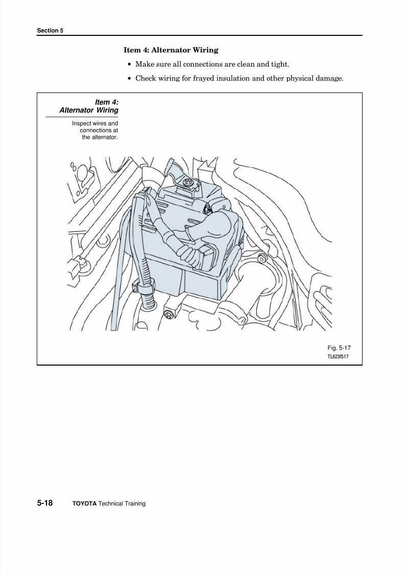
The charging system requires little maintenance. The battery shouldbe fully charged and connections kept clean and tight.
Diagnosis of charging system problems is typically straightforward.Problems may be electrical or mechanical.
The troubleshooting flow diagram on the next page lists the mostcommon charging system problems, the possible cause, andrecommended actions to resolve the problem.
Begin with a thorough visual inspection. If this fails to turn up thepossible cause, several tests are available to help you find the problem:
• Alternator output test (no load)
• Alternator output test (with load)
• Voltage drop tests
• Charging current relay test
• Diode tests
Diagnosisand Testing
8/12/2019 he thong nap tren o to
http://slidepdf.com/reader/full/he-thong-nap-tren-o-to 13/26
The Charging System
Electrical Circuit Diagnosis - Course 623 5-13
Use this flow diagram to troubleshoot charging systems with compact,high speed alternators.
Troubleshooting Flow Diagram
Fig. 5-12TL623f512
TroubleshootingFlow Diagram
8/12/2019 he thong nap tren o to
http://slidepdf.com/reader/full/he-thong-nap-tren-o-to 14/26
Section 5
5-14 TOYOTA Technical Training
Include the following items in a visual inspection of the charging system:
1. Battery
2. Fusing
3. Alternator Drive Belt
4. Alternator Wiring
5. Noise
6. Charging Indicator
Item 1: Battery
Inspect the battery forthe defects shown
in this figure.
Fig. 5-13TL623f513c
Charging SystemVisual Inspection
8/12/2019 he thong nap tren o to
http://slidepdf.com/reader/full/he-thong-nap-tren-o-to 15/26
The Charging System
Electrical Circuit Diagnosis - Course 623 5-15
Other Battery Checks
State of Charge − Check the specific gravity of the electrolyte todetermine the battery’s state of charge.
• Specific gravity should be between 1.25 and 1.27 (at 80 ° F/26.7 ° C).
Condition − Check overall battery condition with a battery analyzer.
Other Battery Checks
A hydrometer can tellyou the battery’s state
of charge.
Fig. 5-14TL623f514
8/12/2019 he thong nap tren o to
http://slidepdf.com/reader/full/he-thong-nap-tren-o-to 16/26
Section 5
5-16 TOYOTA Technical Training
Item 2: Fusing
• Refer to the EWD to identify fuses and fusible links in the charging system for the vehicle under test.
• Check these components for continuity.
Item 2: Fusing
Fusible links must be partof the visual inspection of
the charging system.
Fig. 5-15TL623f515
8/12/2019 he thong nap tren o to
http://slidepdf.com/reader/full/he-thong-nap-tren-o-to 17/26
The Charging System
Electrical Circuit Diagnosis - Course 623 5-17
Item 3: Alternator Drive Belt
• Good condition
• Correct alignment
• Proper tension
Item 3: Alternator Drive Belt
Alternator drive belts must be ingood condition and be properly
aligned and tensioned.
Fig. 5-16TL623f516c
8/12/2019 he thong nap tren o to
http://slidepdf.com/reader/full/he-thong-nap-tren-o-to 18/26
Section 5
5-18 TOYOTA Technical Training
Item 4: Alternator Wiring
• Make sure all connections are clean and tight.
• Check wiring for frayed insulation and other physical damage.
Item 4: Alternator Wiring
Inspect wires andconnections atthe alternator.
Fig. 5-17TL623f517
8/12/2019 he thong nap tren o to
http://slidepdf.com/reader/full/he-thong-nap-tren-o-to 19/26
The Charging System
Electrical Circuit Diagnosis - Course 623 5-19
Item 5: Alternator Noise
Listen for any unusual noise while the alternator is operating:
• Squealing may indicate a bearing problem or a worn or improperlytensioned and adjusted drive belt.
• Hissing may be a sign that one or more of the diodes are defective,because of a pulsating magnetic field and vibration.
Item 5: Alternator Noise
Alternator noise may beimportant in diagnosing
potential problems.
Fig. 5-18TL623f518
8/12/2019 he thong nap tren o to
http://slidepdf.com/reader/full/he-thong-nap-tren-o-to 20/26
Section 5
5-20 TOYOTA Technical Training
Item 6: Charging Indicator
• Indicator lights with ignition ON and engine not running.
• Indicator goes off with engine running.
If the indicator does not operate as described above, refer to theappropriate EWD and check the indicator circuit.
Item 6: Charging Indicator
The Charging indicatorshould be on with the
ignition on and the enginenot running and off with
the engine running.
Fig. 5-19TL623f519c
8/12/2019 he thong nap tren o to
http://slidepdf.com/reader/full/he-thong-nap-tren-o-to 21/26
The Charging System
Electrical Circuit Diagnosis - Course 623 5-21
Use the following steps to perform the test with a Sun VAT−40 or VAT−60tester:
1. Set the tester’s Load control to OFF.
2. Connect the tester leads.
• Red lead to positive terminal.• Black lead to negative terminal.
• Clamp the ammeter clamp−on probe onto the battery’s ground cable.
3. Set the tester’s voltage range to the appropriate setting.
4. Zero both meters on the tester, if needed.
5. Turn the ignition switch to ON (do not start the engine).
Alternator Output Test (No Load)
A VAT-40 Battery Testeris connected for the no
load output test.
Fig. 5-20TL623f520c
Alternator OutputTest (No Load)
8/12/2019 he thong nap tren o to
http://slidepdf.com/reader/full/he-thong-nap-tren-o-to 22/26
Section 5
5-22 TOYOTA Technical Training
6. Record the ammeter reading.
• This is the discharge current (typically about 6 amps).
• Alternator must supply this amount of current before it canprovide charging current to the battery.
7. Start the engine and adjust engine speed to about 2,000 RPM.
8. Allow engine to warm up for 3 to 4 minutes.
9. Record the ammeter reading.
• Add the discharge current (from Step 4) to the reading now onthe ammeter. The total should be less than 10 amps.
• The battery may not have been fully charged if the total currentis more than 10 amps. Monitor the ammeter; the reading shoulddecrease as the battery charges.
10. Record the voltmeter reading.• The voltmeter reading should be within specification for the
alternator during the entire test. This value is typically between13 and 15 volts; refer to the appropriate service manual for thecorrect specification.
• If the voltmeter reading is higher than specified, the voltageregulator is probably defective. Replace the regulator if possibleor replace the alternator.
• If the voltmeter reading is lower than specified, the cause could
be a bad regulator or a fault in the alternator windings. Replacethe alternator if it has an internal voltage regulator.
• For alternators with externally mounted regulators, confirm thecause by grounding Terminal F on the alternator. This bypassesthe regulator. If voltage increases, the voltage regulator isprobably defective. If the voltage remains low, replace thealternator; there is a problem with the windings.
11. Remove ground from alternator Terminal F.
8/12/2019 he thong nap tren o to
http://slidepdf.com/reader/full/he-thong-nap-tren-o-to 23/26
The Charging System
Electrical Circuit Diagnosis - Course 623 5-23
Use the following steps to perform the test with a Sun VAT−40 or VAT−60 tester:
1. Keep the tester connections as for the alternator output test withno load.
2. Adjust engine speed to specified RPM (refer to the appropriateservice manual).
3. Adjust the tester’s load control to obtain the highest ammeter reading possible while keeping the voltage reading at or above 12 volts.
4. Record the highest ammeter reading.
• The reading should be within 10% of the alternator’s rated output.
• Replace the alternator if the reading is more than 10% below thevalue specified.
Alternator Output Test (With Load)
This figure shows the location of the “F”terminal for various alternator types.
Fig. 5-21TL623f521
Alternator OutputTest (With Load)
8/12/2019 he thong nap tren o to
http://slidepdf.com/reader/full/he-thong-nap-tren-o-to 24/26
Section 5
5-24 TOYOTA Technical Training
Voltage drop tests can isolate unwanted high resistance in the charging system. High resistance can cause these symptoms:
• Charging system cannot fully charge battery.
• Abnormally high current is drawn from battery under high load
conditions.
Use a DMM to perform a voltage drop test on the positive sideof the battery as follows:
1. Connect the red meter lead to Terminal B on the alternator.
2. Connect the black meter lead to the positive battery terminal.
3. Start the engine; adjust engine speed to 2,000 RPM.
4. Note the voltage reading.
• The voltage drop should be less than 0.2 volts.
• If the reading is higher, look for poor connections at the alternatorand at the battery. Also, look for damaged wires or corroded wires.
Test for voltage drop on the ground side of the battery as follows:
5. Keep the engine running at 2.000 RPM.
6. Connect the red meter lead to the negative (ground) batteryterminal.
7. Connect the black meter lead to the alternator frame.
8. Note the voltage reading.
• The voltage drop should be less than 0.2 volts.
• If the reading is higher, look for poor connections between thebattery and ground and from the alternator frame to ground.
Also, look for a damaged or corroded battery ground cable.
Voltage Drop Test
8/12/2019 he thong nap tren o to
http://slidepdf.com/reader/full/he-thong-nap-tren-o-to 25/26
The Charging System
Electrical Circuit Diagnosis - Course 623 5-25
Voltage Drop Test
Voltage drop tests canisolate high resistance in
the charging system. Testvoltage drop on the
positive and the groundside of the battery.
Fig. 5-22TL623f522c