Heat and mass transfer in gas metal arc welding. Part I: The arc J. Hu 1 , H.L. Tsai * Department of Mechanical and Aerospace Engineering, University of Missouri–Rolla, 1870 Miner Circle, Rolla, MO 65409, United States Received 18 January 2006; received in revised form 22 August 2006 Available online 24 October 2006 Abstract A unified comprehensive model was developed to simulate the transport phenomena occurring during the gas metal arc welding pro- cess. An interactive coupling between arc plasma; melting of the electrode; droplet formation, detachment, transfer, and impingement onto the workpiece; and weld pool dynamics all were considered. Based on the unified model, a thorough investigation of the plasma arc characteristics during the gas metal arc welding process was conducted. It was found that the droplet transfer and the deformed weld pool surface have significant effects on the transient distributions of current density, arc temperature and arc pressure, which were nor- mally assumed to be constant Gaussian profiles. Ó 2006 Elsevier Ltd. All rights reserved. Keywords: GMAW; Arc plasma; Heat transfer; Fluid flow 1. Introduction Gas metal arc welding (GMAW) is an arc welding pro- cess that uses a plasma arc between a continuous, consum- able filler-metal electrode and the weld pool, as shown in Fig. 1. The high temperature plasma arc melts the electrode and forms a droplet at the electrode tip. The droplet is detached and transferred in the arc to the workpiece. A weld pool forms under the influences of the arc plasma and the periodical impingement of droplets. The formation of droplet, the transfer of droplet in the arc, and the dynamics of weld pool are governed by the balance of forces and the heat transfer inside the droplet or within the weld pool and the heat transferred from the arc plasma. The forces include gravity, surface tension, electromagnetic force, arc pressure, and plasma shear stress. The balance of the forces at the droplet determines the shape, volume, and frequency of the droplet detachment and the droplet accel- eration after the detachment. The weld pool dynamics are not only influenced by the balance of forces acting on it, but are also affected by droplet impingement. The heat transfer within the droplet and weld pool includes Ohmic heating, conduction, and convection. The heat transferred from the arc plasma includes conduction and heat through thermal effect at the surface of the anode and cathode. Most of these forces and heat flux terms change as a func- tion of time. They depend on the instantaneous electrode and weld pool configurations; the droplet position; the cur- rent density distribution within the arc, the electrode, and the weld pool; the thermophysical properties and the fluid flow of the plasma; and the energy balance of the plasma, the electrode, and the workpiece. Modeling the heat transfer and fluid flow in the arc plasma for GTAW [1–18] has been well documented, but very few research articles can be found for GMAW. Mck- elliget and Szekely [1], Choo et al. [2] and Goodarzi et al. [3] have simulated the arc column by assuming the current density distribution at the cathode surface in GTAW. Fan et al. [4,5] used fixed temperature boundary conditions at the cathode tip to calculate the arc column in GTAW. Zhu et al. [6] developed a unified model to simulate the 0017-9310/$ - see front matter Ó 2006 Elsevier Ltd. All rights reserved. doi:10.1016/j.ijheatmasstransfer.2006.08.025 * Corresponding author. Tel.: +1 573 341 4945; fax: +1 573 341 4607. E-mail address: [email protected](H.L. Tsai). 1 Current address: Department of Mechanical Engineering, University of Bridgeport, Bridgeport, CT 06604, United States. www.elsevier.com/locate/ijhmt International Journal of Heat and Mass Transfer 50 (2007) 833–846
Transcript
www.elsevier.com/locate/ijhmt
International Journal of Heat and Mass Transfer 50 (2007) 833–846
Heat and mass transfer in gas metalarc welding. Part I: The arc
J. Hu 1, H.L. Tsai *
Department of Mechanical and Aerospace Engineering, University of Missouri–Rolla, 1870 Miner Circle, Rolla, MO 65409, United States
Received 18 January 2006; received in revised form 22 August 2006Available online 24 October 2006
Abstract
A unified comprehensive model was developed to simulate the transport phenomena occurring during the gas metal arc welding pro-cess. An interactive coupling between arc plasma; melting of the electrode; droplet formation, detachment, transfer, and impingementonto the workpiece; and weld pool dynamics all were considered. Based on the unified model, a thorough investigation of the plasmaarc characteristics during the gas metal arc welding process was conducted. It was found that the droplet transfer and the deformed weldpool surface have significant effects on the transient distributions of current density, arc temperature and arc pressure, which were nor-mally assumed to be constant Gaussian profiles.� 2006 Elsevier Ltd. All rights reserved.
Gas metal arc welding (GMAW) is an arc welding pro-cess that uses a plasma arc between a continuous, consum-able filler-metal electrode and the weld pool, as shown inFig. 1. The high temperature plasma arc melts the electrodeand forms a droplet at the electrode tip. The droplet isdetached and transferred in the arc to the workpiece. Aweld pool forms under the influences of the arc plasmaand the periodical impingement of droplets. The formationof droplet, the transfer of droplet in the arc, and thedynamics of weld pool are governed by the balance offorces and the heat transfer inside the droplet or withinthe weld pool and the heat transferred from the arc plasma.The forces include gravity, surface tension, electromagneticforce, arc pressure, and plasma shear stress. The balance ofthe forces at the droplet determines the shape, volume, andfrequency of the droplet detachment and the droplet accel-
0017-9310/$ - see front matter � 2006 Elsevier Ltd. All rights reserved.
1 Current address: Department of Mechanical Engineering, Universityof Bridgeport, Bridgeport, CT 06604, United States.
eration after the detachment. The weld pool dynamics arenot only influenced by the balance of forces acting on it,but are also affected by droplet impingement. The heattransfer within the droplet and weld pool includes Ohmicheating, conduction, and convection. The heat transferredfrom the arc plasma includes conduction and heat throughthermal effect at the surface of the anode and cathode.Most of these forces and heat flux terms change as a func-tion of time. They depend on the instantaneous electrodeand weld pool configurations; the droplet position; the cur-rent density distribution within the arc, the electrode, andthe weld pool; the thermophysical properties and the fluidflow of the plasma; and the energy balance of the plasma,the electrode, and the workpiece.
Modeling the heat transfer and fluid flow in the arcplasma for GTAW [1–18] has been well documented, butvery few research articles can be found for GMAW. Mck-elliget and Szekely [1], Choo et al. [2] and Goodarzi et al.[3] have simulated the arc column by assuming the currentdensity distribution at the cathode surface in GTAW. Fanet al. [4,5] used fixed temperature boundary conditions atthe cathode tip to calculate the arc column in GTAW.Zhu et al. [6] developed a unified model to simulate the
Av constant, defined in Eq. (19)Bh self-induced azimuthal magnetic fieldc specific heatC coefficient, defined in Eq. (11)c1 permeability coefficient, defined in Eq. (10)d dendrite arm spacinge electronic chargeF volume of fluid functionf mass fractiong volume fraction or gravitational accelerationh enthalpyH latent heat of fusionHev latent heat of vaporizationI welding currentJa anode current densityJr radial current densityJz axial current densityk thermal conductivityK permeability, defined in Eq. (10)kb Stefan–Boltzmann constantkeff effective thermal conductivity at arc-metal inter-
face~n vector normal to the local free surfacep pressurePatm atmospheric pressureps surface tension pressureQ shielding gas flow rateqev evaporation mass rate of metal vaporr-z cylindrical coordinate systemR gas constantRn internal radius of the shielding gas nozzleRw radius of the electrode~s vector tangential to the local free surfaceSa anode sheath energy heat flux for the metalSap anode sheath energy heat flux for the arc plasmaSc cathode sheath energy heat flux for the metalScp cathode sheath energy heat flux for the arc plas-
maSR radiation heat loss
t timeT temperatureTarc arc plasma temperature close to the anode and
bT thermal expansion coefficientc surface tension coefficientoc/oT surface tension temperature gradiente surface radiation emissivityj free surface curvaturell dynamic viscosityl0 magnetic permeability/ electric potential/w work function of the anode materialre electrical conductivityq densitysps plasma shear stresssMs Marangoni shear stressd length of the anode or cathode sheathDt time interval
834 J. Hu, H.L. Tsai / International Journal of Heat and Mass Transfer 50 (2007) 833–846
arc column, the cathode and the cathode sheath in GTAW.Lowke et al. [7,8] simplified the unified model to treat theelectrode in a special way at the cathode surface to accountfor electrode effects [7] or omit the electrode sheath [8]. Thesimplified models [7,8] reduced the computation time to 1%of the original unified model and gave fair results in agree-ment with experimental data when 0.005–0.01 cm mesh sizearound the cathode tip was chosen. These simplified mod-els have been used and further developed by manyresearchers [9–18] to calculate the heat transfer and fluidflow in the arc column.
Both GTAW and GMAW have a plasma arc struckbetween an electrode and a workpiece. Even though the
GTAW has an inert tungsten cathode as the electrodeand the electrode of GMAW is a melting metal and usuallyset as the anode, the GTAW arc model can be adopted tomodel the GMAW arc. Jonsson [19] adopted the GTAWarc model of Mckelliget and Szekely [1] to calculate thearc column by assuming a current density distribution atthe cathode spot. Zhu et al. [20] calculated the anode tem-perature profile by incorporating the simplified arc modelof Lowke et al. [8] into a one-dimensional conductionmodel of the moving electrode in GMAW. The heat inputto the electrode was estimated from the arc plasma, and the‘molten’ metal was discarded when its temperature reachedthe melting point. Haidar and Lowke [21] and Haidar [22]
Cathode (-)Workpiece Weld pool
Metal droplet
C D
EFG
Contact tube Shielding gas nozzle
Shielding gasvelocity profileAnode (+)
Electrode
Arc
R
Z
Cathode (-)Workpiece Weld pool
Cathode (-)Workpiece Weld pool
A B
t t
Cathode (-)Workpiece Weld pool
Fig. 1. A schematic representation of a GMAW system including theelectrode, the arc, and the weld pool (not to scale).
J. Hu, H.L. Tsai / International Journal of Heat and Mass Transfer 50 (2007) 833–846 835
extended the simplified arc model of Lowke et al. [8] to sim-ulate the droplet formation in GMAW. They were the firstto simulate the dynamic interaction of the arc plasma andthe droplet. Haidar [13,23,24] further developed thisGMAW model to take into account the sheath effect atthe anode surface. However, the droplet was eliminatedimmediately when it was detached from the electrode tip.The weld pool dynamics was also neglected and the work-piece was treated as a flat plate. The fluid flow in the weldpool was not calculated and only conduction was consid-ered. Zhu et al. [25] and Fan and Kovacevic [26] havedeveloped models to simulate the arc column, droplet for-mation, detachment, transfer and impingement onto theworkpiece and the weld pool dynamics. However, the sim-ulated arc plasma distributions matched both the experi-mental results [27–31] and the simulation results fromaforementioned arc models [1–24] poorly. From the simu-lated fluid flow within the droplets in Ref. [25], the couplingof the arc plasma and the droplets seemed to be poor as thedroplets showed very little sign of being subjected to theelectromagnetic force, arc pressure, and plasma shearforce. The arc plasma flow in Ref. [26] could not pushthe detached droplets down and an empirical formulationwas used to calculate the plasma drag force.
In almost all of the aforementioned studies, the arcplasma was considered to be independent of electrode melt-ing, droplet generation and transfer, or weld pool dynam-ics. However, in reality, the surface of the weld pool ishighly deformable, and the profile of the electrode changesrapidly. Also, when there are droplets between the elec-trode tip and the surface of the welding pool, the flow ofarc plasma can be dramatically distorted. In this article, amathematical model employing the volume of fluid(VOF) technique and the continuum formulation is devel-oped to simulate the coupled transport phenomena includ-
ing the generation and changes of the arc plasma; theelectrode melting; the droplet formation, detachment,transfer, and impingement onto the workpiece; and thedynamics of the weld pool. This paper will focus on pre-senting the results of the plasma arc. A second paper onthe electrode melting; droplet formation, transfer, detach-ment and impingement onto the base metal; and thedynamics of the welding pool is presented separately.
2. Mathematical model
2.1. Governing equations
Fig. 1 is a schematic sketch of a stationary axisymmetricGMAW system. In this system, a constant current isapplied to the electrode through the contact tube at thetop of the computational domain. An arc plasma is struckbetween the electrode and the workpiece. The electrode iscontinuously fed downward and then melted at the tip bythe high temperature arc. Droplets are formed at the mol-ten electrode tip, and are then detached and transferred tothe workpiece. A weld pool is formed by the continuousimpingement of droplets and dynamic interaction withthe high temperature and high pressure arc plasma at theworkpiece. Inert shielding gas is provided through theshielding gas nozzle to prevent the molten metal fromoxidation.
The computational domain has an anode region, an arcregion and a cathode region. For GMAW, the anoderegion is the electrode, and the cathode region is the work-piece. The anode sheath region and the cathode sheathregion have been omitted and treated as special boundaryconditions in this model for computational simplification[7,8]. The differential equations governing the arc, the elec-trode, and the workpiece can be put into a single set. Thedifferential equations governing the conservation of mass,momentum, and energy based on the continuum formula-tion given by Diao and Tsai [32] are employed in the pres-ent study, and the current continuity equation is used tocalculate the current density distribution. The equationsare given below:
Mass continuity
o
otðqÞ þ r � ðqVÞ ¼ 0 ð1Þ
Momentum
o
otðquÞ þ r � ðqVuÞ
¼ r � ll
qql
ru� �
� opor� ll
Kqql
ðu� usÞ
� Cq2
K1=2ql
ju� usjðu� usÞ � r � ðqfsflV rurÞ � J z � Bh
ð2Þ
836 J. Hu, H.L. Tsai / International Journal of Heat and Mass Transfer 50 (2007) 833–846
o
otðqvÞ þ r � ðqVvÞ
¼ r � ll
qql
rv� �
� opoz� ll
Kqql
ðv� vsÞ
� Cq2
K1=2ql
jv� vsjðv� vsÞ � r � ðqfsflV rvrÞ
þ qgbTðT � T 0Þ þ J r � Bh ð3Þ
Energy
o
otðqhÞ þ r � ðqVhÞ
¼ r � kcs
rh� �
þr � kcs
rðhs � hÞ� �
�r � ðqðV � V sÞðhl � hÞÞ � DHofl
otþ J 2
r þ J 2z
re
� SR þ5kb
eJ r
cs
ohorþ J z
cs
ohoz
� �ð4Þ
Current continuity
r2/ ¼ 1
ro
orro/or
� �þ o2/
oz2¼ 0 ð5Þ
Ohm’s law
J r ¼ �re
o/or; J z ¼ �re
o/oz
ð6Þ
Maxwell’s equation
Bh ¼l0
r
Z r
0
J zrdr ð7Þ
In Eqs. (1)–(4), u and v are the velocities in the r and z
directions, respectively. Vr = Vl � Vs is the relative velocityvector between the liquid phase and the solid phase in themushy zone. The subscripts s and l refer to the solid andliquid phases, respectively, and the subscript 0 representsthe initial condition. f is the mass fraction of the liquidor solid; K is the permeability function; C is the inertialcoefficient; p is the pressure; T is the temperature; h is theenthalpy; U is the electrical potential; q is the density; lis the viscosity; k is the thermal conductivity; g is thegravitational acceleration; bT is the thermal expansioncoefficient; c is the specific heat; re is the electricalconductivity; Jr and Jz are current densities, in the respec-tive r and z directions; Bh is the self-induced electromag-netic field; SR is the radiation heat loss; l0 is themagnetic permeability; kb is the Stefan–Boltzmann con-stant; and e is the electronic charge.
The third and fourth terms on the right-hand side of Eqs.(2) and (3) represent the respective first- and second-orderdrag forces for the flow in the mushy zone. The fifth termon the right-hand side of Eqs. (2) and (3) represents aninteraction between the solid and the liquid phases. The sec-ond term on the right-hand side of Eq. (4) represents the netFourier diffusion flux. The third term represents the energyflux associated with the relative phase motion, and the forthterm is used to consider the latent heat of fusion. All the
terms mentioned in this paragraph are zero, except in themushy zone. When Eqs. (2)–(4) are used to calculate thearc plasma, these terms associated with the mushy zoneare set to zero and all the thermal physical properties arereplaced with those of the arc plasma. In the present study,the solid phase velocity is assumed to be zero due to arelative small weld pool (as compared to, for example, acasting), concentrated arc heat, and rapid solidification ofthe weld pool after the arc is turned off.
The second-to-last term on the right-hand side of Eq. (3)is the thermal expansion term. The last term of Eqs. (2) and(3) is the electromagnetic force term. The last three terms inEq. (4) are Ohmic heating, radiation loss, and energy trans-fer due to electron flow, respectively [6–9]. Electronenthalpy flow has been omitted in the energy equationdue to its strong cooling effect in the cathode region andheating effect in the anode region [6–9,21–23].
Continuum density, specific heat, thermal conductivity,solid mass fraction, liquid mass fraction, velocity, andenthalpy are defined as follows:
q ¼ gsqs þ glql; c ¼ fscs þ flcl; k ¼ gsks þ glkl
fs ¼gsqs
q; fl ¼
glql
q
V ¼ fsV s þ flV l; h ¼ hsfs þ hlfl
ð8Þ
Assuming constant phase specific heats, the phaseenthalpy for the solid and liquid can be expressed as
hs ¼ csT ; hl ¼ clT þ ðcs � clÞT s þ H ð9Þ
where H is the latent heat of fusion for the alloy.The assumption of permeability function in the mushy
zone requires consideration of the growth morphology spe-cific to the alloy under study. In the present study, the perme-ability function analogous to fluid flow in porous media isassumed, employing the Carman–Kozeny equation [33,34]
K ¼ g3l
c1ð1� glÞ2; c1 ¼
180
d2ð10Þ
where d is proportional to the dendrite dimension, which isassumed to be a constant and is on the order of 10�2 cmThe inertial coefficient, C, can be calculated from [35]
C ¼ 0:13g�3=2l ð11Þ
2.2. Arc region
In the arc region, the plasma is assumed to be in localthermodynamic equilibrium (LTE) [8], implying the elec-tron and the heavy particle temperatures are equal. On thisbasis, the plasma properties, including enthalpy, specificheat, density, viscosity, thermal conductivity and electricalconductivity, are determined from an equilibrium composi-tion calculation [8,36]. It is noted that the metal vaporizedfrom the metal surface may influence plasma materialproperties, but this effect is omitted in the present study.It is also assumed that the plasma is optically thin, thus
J. Hu, H.L. Tsai / International Journal of Heat and Mass Transfer 50 (2007) 833–846 837
the radiation may be modeled in an approximate mannerby defining a radiation heat loss per unit volume as indi-cated by SR in Eq. (4) [8,36].
2.3. Metal region (electrode, droplet and workpiece)
In this model, the anode region and cathode regionchange their shapes with time. Together with detacheddroplets in the arc, they consist of the metal region, whichis occupied by metal. The temperature distribution withinthe metal region is at an energy balance of conduction,Ohmic heating, and convection in the metal and the heattransferred from the arc plasma. Considerations are alsogiven to energy gains and losses due to latent heat resultingfrom melting and solidification at the solid–liquid interface.Changes in the shape of the electrode tip and the weld poolsurface result in changes in the current distribution, theheat generated due to Ohmic heating, and the heat trans-ferred from the arc to the metal surface.
2.4. Tracking of solid–liquid interface
The solid/liquid phase-change boundary is handled bythe continuum model [32]. The third, fourth, and fifthterms on the right-hand-side of Eqs. (2) and (3) vanish atthe solid phase because u = us = v = vs = 0 and fl = 0.For the liquid region, since K goes to infinity due togl = 1 in Eq. (7) and fs = 0, all the aforementioned termsalso vanish. These terms are only valid in the mushy zone,where 0 < fl < 1 and 0 < fs < 1. Therefore, there is no needto explicitly track the phase-change boundaries, and theliquid region, mushy zone, and solid region are all calcu-lated by the same Eqs. (2) and (3). During the fusion andsolidification processes, the latent heat is absorbed orreleased in the mushy zone, which is handled through theuse of enthalpy defined in Eq. (9).
2.5. Tracking of free surfaces
Precise tracking of the free surface of the droplet and thewelding pool are essential to correctly predicting the shapeof the droplet and the weld pool as a function of time. Thealgorithm of volume-of-fluid (VOF) is used to track themoving free surface [37]. The fluid configuration is definedby a volume of fluid function,F(r,z, t), which tracks thelocation of the free surface. This function represents thevolume of fluid per unit volume and satisfies the followingconservation equation
dFdt¼ oF
otþ ðV � rÞF ¼ 0 ð12Þ
When averaged over the cells of a computing mesh, theaverage value of F in a cell is equal to the fractional volumeof the cell occupied by the metal. A unit value of F corre-sponds to a cell full of metal, whereas a zero value indicatesthe cell contains no metal. Cells with F values between zeroand one are partially filled with metal.
2.6. Forces at the arc plasma and metal interface
The molten part of the metal is subjected to body forcessuch as gravity and electromagnetic force. It is also sub-jected to surface forces such as surface tension due to sur-face curvature, Marangoni shear stress due to temperaturedifference, and arc plasma shear stress and arc pressure atthe arc plasma and metal interface.
For cells containing a free surface, surface tension pres-sure normal to the free surface can be expressed as [38]
ps ¼ cj ð13Þwhere c is the surface tension coefficient and j is the freesurface curvature given by
j ¼ � r � ~nj~nj
� �� �¼ 1
j~nj~nj~nj � r� �
j~nj � ðr �~nÞ� �
ð14Þ
where ~n is a vector normal to the local free surface whichequals the gradient of the VOF function
~n ¼ rF ð15ÞThe temperature-dependent Marangoni shear stress at
the free surface in a direction tangential to the local freesurface is given by [30]
sMs ¼ocoT
oTo~s
ð16Þ
where~s is a vector tangential to the local free surface.The arc plasma shear stress is calculated at the free sur-
face from the velocities of the arc plasma cells immediatelynext to the metal cells.
sps ¼ loV
o~sð17Þ
where l is the viscosity of arc plasma.The arc pressure at the metal surface is obtained from the
computational result in the arc region. The surface forcesare included by adding source terms to the momentum equa-tions according to the CSF (continuum surface force) model[38–40]. Using F of the VOF function as the characteristicfunction, surface tension pressure, Marangoni shear stress,arc plasma shear stress, and arc pressure are all transformedto the localized body forces and added to the momentumtransport equations as source terms at the boundary cells.
2.7. Energy terms at the arc plasma and metal interface
2.7.1. Plasma–anode interface
At the plasma–electrode interface, there exists an anodesheath region [8]. In this region, the mixture of plasma andmetal vapor departs from LTE, thus it no longer complieswith the model presented above. The thickness of this regionis about 0.02 mm [8]. Since the sheath region is very thin, it istreated as a special interface to take into account the thermaleffects on the electrode. The energy balance equation at thesurface of the anode is modified to include an additionalsource term, Sa, as the following [13,21] for the metal region
838 J. Hu, H.L. Tsai / International Journal of Heat and Mass Transfer 50 (2007) 833–846
Sa ¼keffðT arc � T aÞ
dþ J a/w � ekbT 4
a � qevH ev ð18Þ
The first term on the right-hand side of Eq. (18) is thecontribution due to thermal conduction from the plasmato the anode. The symbol keff represents the thermal con-ductivity taken as the harmonic mean of the thermal con-ductivities of the arc plasma and the anode material. d isthe length of the anode sheath region, which is taken as0.1 mm, the maximum experimentally observed thicknessof the anode fall region [41]. Tarc is chosen to be the tem-perature of the first gas plasma cell along the normal direc-tion, and Ta to be the temperature of the first metal cellalong the normal direction at the local point. The secondterm represents the electron heating associated with thework function of the anode material. Ja is the square rootof J 2
r and J 2z and /w is the work function of the anode
material. The third term is black body radiation loss fromthe anode surface. The final term is the heat loss due to theevaporation of electrode materials. e is the emissivity ofthe surface and kb is the Stefan–Boltzmann constant. qev
is the mass rate of evaporation of metal vapor from thedroplet, and Hev is the latent heat of vaporization. Formetal such as steel, qev can be written as [39]
logðqevÞ ¼ Av þ log P atm � 0:5 log T ð19Þ
log P atm ¼ 6:121� 18836
Tð20Þ
At the arc–anode interface, the energy equation for theplasma only considers the cooling effects through conduc-tion and the source term, Sap, is given
Sap ¼ �keffðT arc � T aÞ
dð21Þ
2.7.2. Plasma–cathode interface
Similar to the anode region, there exists a cathodesheath region between the plasma and the cathode. How-ever, the physics of the cathode sheath and the energy bal-ance at the nonthermionic cathode for GMAW are not wellunderstood [19–24,36]. The thermal effect due to the cath-ode sheath has been omitted in many models and reason-able results were obtained [8,20–24]. Thus, the energybalance equation at the cathode surface will only havethe conduction, radiation, and evaporation terms
Table 1Boundary conditions on the outer boundaries
AB BC CD
u 0 0 0
v vw Eq. (24)oðqvÞ
oz¼ 0
h T = 300 K T = 300 K T = 300 K
/ �ro/oz¼ I
pR2c
o/oz¼ 0
o/oz¼ 0
Sc ¼keffðT arc � T cÞ
d� qevH ev � ekbT 4
c ð22Þ
where keff is the effective thermal conductivity at the arc–cathode surface taken as the harmonic mean of the thermalconductivities of the arc plasma and the cathode material. dis the length of the cathode and is taken as 0.1 mm. Tc isthe cathode surface temperature. And the heat loss fromthe plasma at the cathode surface is
Scp ¼ �keffðT arc � T cÞ
dð23Þ
2.8. Boundary conditions
2.8.1. External boundary conditions
The calculation domain, as shown in Fig. 1, is ABC-DEFGA. Only half of the entire physical domain is calcu-lated due to the cylindrical symmetry along the centerlineAG. The corresponding external boundary conditions forthe entire domain are listed in Table 1. Symmetrical bound-ary conditions are used along the centerline AG. The wirefeed rate is incorporated through a boundary condition onv along AB. The imposed shielding gas flow is set through aboundary condition on v along BC. For the inflow of gasfrom the nozzle, the radial velocity component is omittedand the axial velocity component is determined from theformula for pipe flow as shown in the following [42]:
vðrÞ ¼ 2Qp
R2n � r2 þ ðR2
n � R2wÞ
lnðr=RnÞlnðRn=RwÞ
n o
R4n � R4
w þðR2
n�R2wÞ
2
lnðRn=RwÞ
n o þ V w
ln Rn
r
ln Rn
Rw
ð24Þ
where Q is the inflow rate of the shielding gas, Rw is the ra-dius of the electrode, Rn is the internal radius of the shield-ing gas nozzle, and Vw is the wire feed rate. A constantmass flow boundary condition is used for the open bound-aries CD and DE.
The temperature boundaries along AD, DE, and EG aredetermined by the ambient condition, which is set as roomtemperature. Uniform current density is specified along ABas J z ¼ �re
o/oz ¼ I
pR2w. The voltage, /, is set to zero at the
bottom of the workpiece FG.
2.8.2. Internal boundary conditions
Within the computational domain, the moving surfaceof the electrode, droplet and weld pool forms the inner
DE EF FG GA
oðquÞor¼ 0
0 0 0
0 0 0ovor¼ 0
T = 300 K T = 300 K T = 300 KoTor¼ 0
o/or¼ 0 / = 0 / = 0
o/or¼ 0
J. Hu, H.L. Tsai / International Journal of Heat and Mass Transfer 50 (2007) 833–846 839
boundary for the arc region. VOF Eq. (12) is solved in themetal domain to track the moving free surface with freeboundary conditions set at the metal free surface. Addi-tional body force source terms are added to the momentumtransport equations at the metal free surface to consider theeffects of surface tension, Maragoni shear stress, arcplasma shear stress and arc pressure. Additional sourceterms described in Eqs. (18) and (22) are added to theenergy equation for the special treatment of the anodesheath and the cathode sheath.
A fixed computational domain is used to solve the equa-tions in the arc region. The metal region is used as the innerboundary for the arc region. As the velocity of the metaldomain is much smaller than the velocity of the arc plasma,the metal region serves as an inner obstacle in the arcdomain. The temperature at the metal free surface is con-sidered as the temperature boundary for the arc domain.
3. Numerical considerations
In the present study, the transport phenomena in the arcplasma and the metal are calculated separately in the cor-responding metal domain and arc domain, and the twodomains are coupled through interfacial boundary condi-tions at each time step. The current distribution is greatlyinfluenced by the temperature distribution in the arc col-umn and the shape of the metal domain, but it is slightlyinfluenced by the temperature distribution in the metaldomain as the electrical conductivity of metal variesslightly with temperature. Therefore, the current continuityequation and its associated boundary conditions are solvedin the entire domain, while other primary variables, includ-ing p, u, v, and T, are calculated separately in the metaldomain and arc domain. The current continuity equationis iterated with the transport equations in the arc domainto obtain the current density distribution for both the arcdomain and the metal domain. Iterations are required toassure convergence of each domain and then the boundaryconditions are calculated from each domain for the cou-pling between the two domains.
For the metal domain, the method developed by Torreyet al. [37] was used to solve p, u, v, and T. This method isEulerian and allows for an arbitrary number of segmentsof free surface with any reasonable shape. The basic proce-dure for advancing the solution through one time step, Dt,consists of three steps. First, at the beginning of the timestep, explicit approximations to the momentum Eqs. (2)and (3) are used to find provisional values of the new timevelocities. Second, an iterative procedure is used to solvefor the advanced time pressure and velocity fields that sat-isfy Eq. (1) to within a convergence criterion at the newtime. Third, the energy equation is solved.
For the arc plasma domain, a fully implicit formulationis used for the time-dependent terms, and the combinedconvection/diffusion coefficients are evaluated using anupwind scheme. The SIMPLE algorithm [43] is applied tosolve the momentum and mass continuity equations to
obtain the velocity field. At each time step, the current con-tinuity equation is solved first, based on the updatedparameters. The new distributions of current density andelectromagnetic force are then calculated for the momen-tum and energy equations. The momentum equationsand the mass continuity equation are then solved in theiteration process to obtain pressure and velocity. Theenergy equation is solved to get the new temperature distri-bution. Next, the temperature-dependent parameters areupdated, and the program goes back to the first step to cal-culate the current continuity equation. This process isrepeated for each time step until the convergence criteriaare satisfied.
The governing differential equations (Eqs. (1)–(5) and(12)) and all related supplemental and boundary conditionsare solved through the following iterative scheme:
1. At t = 0, the electrode is set up at an initial position andinitial temperature distribution is given to the metaldomain. Based on the initial fixed metal domain andtemperature distribution, the initial distributions of tem-perature, velocity, pressure and current are obtained bysolving the steady state equations in the arc domain (thisprocedure is similar to the steps from 5–7 for the steadystate).
2. Surface tension, Marangoni shear stress, electromag-netic force, plasma shear stress and arc pressure are cal-culated, and other associated boundary conditions areevaluated for the metal domain.
3. Eqs. (1)–(4) are solved iteratively to obtain pressure,velocity and temperature in the metal domain.
4. Eq. (12) is solved to obtain the new free surface profilefor the metal domain. The physical properties in themesh cells and the boundary conditions within the com-puting domain are updated.
5. The current continuity equation (5) is solved in thewhole domain with updated parameters. Current densityand electromagnetic force are calculated.
6. Eqs. (1)–(3) and the associated boundary conditions aresolved iteratively to get the velocity and pressure distri-butions of the arc plasma. When solving these equa-tions, the electrode, droplet and the workpiece aretreated as fixed inner obstacles.
7. Energy equation (4) is solved in the arc domain to getthe new temperature distribution. Thermal physicalproperties of the arc plasma are updated. From here,the iteration goes back to step 5 to repeat the processfor new distribution of current density, velocity, pres-sure, and temperature, until convergence criteria aresatisfied.
8. Advance to the next time step and back to step 2 untilthe desired time is reached.
A non-uniform grid point system is employed with finergrid sizes near both the cathode and anode regions. Themesh sizes near the anode and cathode center are set as0.01 cm. The calculation domain is half of the cylinder of
l Con
duct
ivit
y (W
/m-K
)
2
4
6
Den
sity
(kg
/m3 )
0.2
0.3
0.4
0.5(a) (b)
840 J. Hu, H.L. Tsai / International Journal of Heat and Mass Transfer 50 (2007) 833–846
5.0 cm radius and 3.05 cm in length. Time step size is set as5 � 10�6 s. Various grid sizes and time step sizes wereemployed to assure consistent computational results. Thefinal grid and time-step sizes used in the present studycan be considered as the compromised values between com-putational time and accuracy.
T (K)
The
rma
10000 20000 300000
T (K)
Spec
ific
hea
t (J
/kg-
K)
10000 20000 300000
5000
10000
T (K)Ele
ctri
cal c
ondu
ctiv
ity
(1/o
hm-m
)
10000 20000 300000
2000
4000
6000
8000
10000
12000
T (K)
Rad
iati
on h
eat
loss
(J/
m3 )
10000 20000 300000
1E+10
2E+10
3E+10
4E+10
T (K)
Dyn
amic
vis
cosi
ty (
kg/m
-s)
10000 20000 300000
0.0001
0.0002
0.0003
T (K)10000 20000 30000
0
0.1
(c) (d)
(e) (f)
Fig. 2. Temperature-dependent material properties of argon and thevolume radiation heat loss taken from [36].
4. Results and discussion
The electrode is mild steel with a 0.16 cm diameter. Theworkpiece is also a mild steel disk with a 3 cm diameter anda 0.5 cm thickness. The current is set to be constant at220 A. The imposed external shielding gas flows out of agas nozzle with a 1.91 cm inner diameter at a rate of 24 l/min. The contact tube is set flush with the bottom of thegas nozzle and is 2.54 cm above the workpiece. The initialarc length is set as 0.8 cm. The wire feed rate is 4.5 cm/s.The welding conditions are listed in Table 2. The tempera-ture-dependent radiation loss term (SR) in Eq. (4) and tem-perature-dependent material properties of argon, includingdensity, specific heat, viscosity, electrical conductivity, andthermal conductivity, are taken from [36] and drawn inFig. 2. The thermophysical properties of the solid andliquid mild steel are taken from [31], and are listed in Table3 with other parameters used in the computation.
Fig. 3(a) through (c), respectively, show the distributionsof temperature, arc plasma velocity, and electrical potentialat t = 100 ms. The shape of the electrode and workpieceare marked with thick lines. From the temperature con-tours in the plasma in Fig. 3(a), it can be seen that thearc has a bell-shaped envelope, which covers the dropletand expands as it approaches the workpiece. This expan-sion cools the plasma and forms a high temperature coneunderneath the droplet. The maximum temperature ofthe plasma is found to be 19300 K on the axis near the bot-tom of the droplet. The corresponding velocity distributionin Fig. 3(b) shows a strong downward arc plasma flowunderneath the droplet. From the streamline, it can beclearly seen that shielding gas flows down from the gas noz-zle along the electrode surface and then is drawn to theelectrode around the electrode tip. The ionized shieldinggas around the electrode tip is pinched by the radially
Table 2Welding conditions
Nomenclature Value (unit)
Shielding gas ArgonShielding gas flow rate 23 (L min�1)Internal diameter of shielding gas nozzle 19.1 (mm)Welding current 220 (A)Electrode diameter 1.6 (mm)Contact tube to workpiece length 25.4 (mm)Initial arc length 8.0 (mm)Workpiece thickness 5.0 (mm)Diameter of workpiece 30.0 (mm)Wire feed speed 4.5 (cm s�1)Welding time 1 (s)
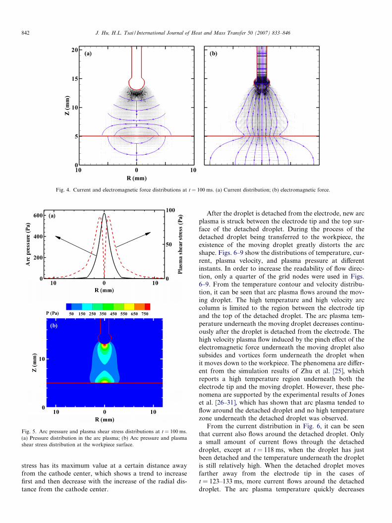
inward and axially downward electromagnetic forcetoward the workpiece. The corresponding electromagneticforce in the arc column is shown in Fig. 4(b). When theplasma flow reaches the workpiece, the axial downwardmomentum is changed to the radial outward momentumand the plasma flows outward in the radial direction. Themaximum axial velocity in the arc column is found to be230 m/s on the axis.
Fig. 3(c) shows the corresponding electrical potentialdistribution at t = 100 ms. There are two distinct regionswhere dense electrical potential contours are observed.One is around the electrode with upside contour andanother is near the cathode with downside contour. Thegradient of the electrical potential is the current density.The electrical potential contours are denser, where the cur-rent density is higher. The upside contour shape shows cur-rent diverges from the center and the downside contourshape shows current converges to the center. From the cor-responding current density distribution in Fig. 4(a), it ismore clearly seen that current diverges from the electrodetip and converges at the cathode in the workpiece. The cur-rent flow pattern determines the inward and downwardelectromagnetic force around the droplet and the inwardand upward electromagnetic force at the workpiece, as
Fig. 3. Temperature, arc plasma velocity and electrical potential distributions at t = 100 ms. (a) temperature distribution; (b) velocity distribution; (c)electrical potential distribution.
Table 3Thermophysical properties of mild steel and other parameters
Nomenclature Symbol Value (unit)
Constant in Eq. (19) Av 2.52Specific heat of solid phase cs 700 (J kg�1 K�1)Specific heat of liquid phase cl 780 (J kg�1 K�1)Thermal conductivity of solid phase ks 22 (W m�1 K�1)Thermal conductivity of liquid phase kl 22 (W m�1 K�1)Density of solid phase qs 7200 (kg m�3)Density of liquid phase ql 7200 (kg m�3)Thermal expansion coefficient bT 4.95 � 10�5 (K�1)Radiation emissivity e 0.4Dynamic viscosity ll 0.006 (kg m�1 s�1)Latent heat of fusion H 2.47 � 105 (J kg�1)Latent heat of vaporization Hev 7.34 � 106 (J kg�1)Solidus temperature Ts 1750 (K)Liquidus temperature Tl 1800 (K)Ambient temperature T1 300 (K)Vaporization temperature Tev 3080 (K)Surface tension coefficient c 1.2 (N m�1)Surface tension temperature gradient oc/oT 10�4 (N m�1 K�1)Work function /w 4.3 VElectrical conductivity re 7.7 � 105 (X�1 m�1)
J. Hu, H.L. Tsai / International Journal of Heat and Mass Transfer 50 (2007) 833–846 841
shown in Fig. 4(b). From the streamlines shown inFig. 4(a), it also can be seen that current is mainly confinedin the arc column and very little amount of current is flow-ing outside the hot arc plasma column. Outside the hightemperature arc column, the temperature of the arc plasmais low and thus the electrical conductivity is low. Note inorder to increase the readability of flow direction, only aquarter of the grid nodes are used in Fig. 4(b).
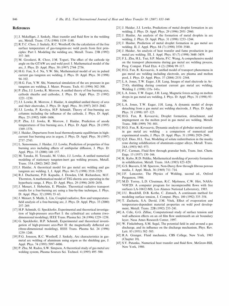
The corresponding arc pressure contours at t = 100 msare shown in Fig. 5(a), which shows two high pressureregions. One is underneath the droplet with a maximumof 800 Pa above the ambient pressure, and the other is near
the cathode with a maximum of 600 Pa above the ambientpressure. The high pressure underneath the droplet iscaused by the pinch effect of the electromagnetic force,which draws arc plasma flow underneath the droplet. Thepressure increase near the cathode is due to the stagnationof the plasma flow impinging onto the workpiece. The arcpressure and shear stress versus the radial distance from thecenter of the workpiece at the workpiece surface are drawnin Fig. 5(b). The arc pressure has a Gaussian distribution,which only has high value in a small area near the cathodecenter and then decreases dramatically when it is awayfrom the cathode center. Quite differently, the plasma shear
Fig. 5. Arc pressure and plasma shear stress distributions at t = 100 ms.(a) Pressure distribution in the arc plasma; (b) Arc pressure and plasmashear stress distribution at the workpiece surface.
Fig. 4. Current and electromagnetic force distributions at t = 100 ms. (a) Current distribution; (b) electromagnetic force.
842 J. Hu, H.L. Tsai / International Journal of Heat and Mass Transfer 50 (2007) 833–846
stress has its maximum value at a certain distance awayfrom the cathode center, which shows a trend to increasefirst and then decrease with the increase of the radial dis-tance from the cathode center.
After the droplet is detached from the electrode, new arcplasma is struck between the electrode tip and the top sur-face of the detached droplet. During the process of thedetached droplet being transferred to the workpiece, theexistence of the moving droplet greatly distorts the arcshape. Figs. 6–9 show the distributions of temperature, cur-rent, plasma velocity, and plasma pressure at differentinstants. In order to increase the readability of flow direc-tion, only a quarter of the grid nodes were used in Figs.6–9. From the temperature contour and velocity distribu-tion, it can be seen that arc plasma flows around the mov-ing droplet. The high temperature and high velocity arccolumn is limited to the region between the electrode tipand the top of the detached droplet. The arc plasma tem-perature underneath the moving droplet decreases continu-ously after the droplet is detached from the electrode. Thehigh velocity plasma flow induced by the pinch effect of theelectromagnetic force underneath the moving droplet alsosubsides and vortices form underneath the droplet whenit moves down to the workpiece. The phenomena are differ-ent from the simulation results of Zhu et al. [25], whichreports a high temperature region underneath both theelectrode tip and the moving droplet. However, these phe-nomena are supported by the experimental results of Joneset al. [26–31], which has shown that arc plasma tended toflow around the detached droplet and no high temperaturezone underneath the detached droplet was observed.
From the current distribution in Fig. 6, it can be seenthat current also flows around the detached droplet. Onlya small amount of current flows through the detacheddroplet, except at t = 118 ms, when the droplet has justbeen detached and the temperature underneath the dropletis still relatively high. When the detached droplet movesfarther away from the electrode tip in the cases oft = 123–133 ms, more current flows around the detacheddroplet. The arc plasma temperature quickly decreases
Fig. 6. Temperature distribution at different instants to show the influences of the detached droplet and the deformed weld pool on the arc plasmadistribution.
Fig. 7. The corresponding current distributions for the cases shown in Fig. 6.
J. Hu, H.L. Tsai / International Journal of Heat and Mass Transfer 50 (2007) 833–846 843
when current flow decreases underneath the detached drop-let due to the high radiation loss and low capacity of theplasma. The lower plasma temperature underneath the
detached droplet further reduces the current flow in theplasma, and hence the plasma temperature continues todrop. At the surface of the workpiece, the current bypassed
Fig. 8. The corresponding velocity distributions in the arc plasma for the cases shown in Fig. 6.
Fig. 9. The corresponding pressure distributions in the arc plasma for the cases shown in Fig. 6.
844 J. Hu, H.L. Tsai / International Journal of Heat and Mass Transfer 50 (2007) 833–846
around the detached droplet tends to converge at a placeother than the spot directly underneath the droplet. As acylindrical system is used in this calculation, a ring of cath-ode spot, rather than a small continuous area, is predicted
for the instants when a detached droplet is stuck betweenthe electrode and the workpiece. In the practical weldingprocess, the current may converge to some small projectedarea other than symmetrically around the workpiece. The
Fig. 10. Arc pressure distributions along the radial direction at theworkpiece surface.
J. Hu, H.L. Tsai / International Journal of Heat and Mass Transfer 50 (2007) 833–846 845
existence of the detached droplet also dramatically changesthe arc pressure distribution underneath the droplet, asshown in Fig. 9. The arc pressure at the tip of the electrodeand at the upper surface of the droplet is mainly influencedby the shapes of the electrode tip and the position of thedetached droplet. After the droplet is detached, a higharc pressure forms between the electrode tip and the uppersurface of the moving droplet. The high arc pressure, whichwas under the droplet before it was detached, decreasesrapidly. The stagnation pressure underneath the dropletat the center of the workpiece also decreases rapidly. Thepressure difference between the upper and lower surfacesof the droplet helps to push the detached droplet downto the workpiece.
In GTAW welding, the cathode tip shape greatly influ-ences the welding results because the cathode tip shapedetermines the current flow into the cathode tip. The moreprojected the cathode, the more concentrated is the currentflow and thus the more concentrated arc plasma withhigher temperature and higher arc pressure. In the sameway, the current distribution at the cathode in GMAW,which is the weld pool, is greatly influenced by the weldpool surface shape. The temperature, current, arc plasmavelocity and arc pressure distributions from t = 136 ms tot = 400 ms in Figs. 6–9 show the influence of the weld poolshape on the arc plasma. The current tends to converge onthe projected area at the workpiece, which may be at theworkpiece center as in the cases of both t = 136 ms andt = 400 ms or not at the center as that of t = 150 ms. Thetemperature distribution and the pressure distribution atthe deformed weld pool surface from t = 136 ms tot = 400 ms in Figs. 6 and 9, also show a different patternfrom those at the flat weld pool surface.
In the existing models of simulating the weld pooldynamics, the arc pressure distribution at the center of theworkpiece surface was assumed to be a Gaussian distribu-tion with a fixed amplitude and distribution radius. How-ever, the arc pressure distribution at the workpiece surface
changes dramatically during the welding process. Fig. 10shows the arc pressure along the weld pool surface at differ-ent instants. As shown in Fig. 10, the arc pressure spreads toa wide surface with lower amplitude when there is adetached droplet stuck between the electrode tip and theworkpiece at t = 133 ms. The deformed weld pool surfacegreatly affects the arc pressure distribution at the weld poolsurface. The depressed weld pool surface at t = 150 mshelps to distribute the arc pressure more uniformly at theweld pool center and reduce the arc pressure where it isaway from the center. The arc pressure distribution is con-centrated at the weld pool center with a projected weld poolsurface at t = 400 ms. A small weld pool is simulated with ashort simulated welding time, while much higher weld pooldeformations can be found in a large weld pool with longwelding time. The highly deformed weld pool surface willmore dramatically change the arc distribution at the weldpool surface. Thus, it shows that the assumed Gaussian dis-tribution of the arc pressure cannot reflect the real arc pres-sure distribution at the weld pool surface. Similarly, thecurrent distribution and heat flux cannot be assumed asGaussian distributions with fixed amplitude and fixed distri-bution radius. The influences of the moving droplet and thedeformed weld pool surface on the current and temperaturedistributions at the weld pool surface have been explainedearlier in this section. The heat flux to the weld pool surfaceis determined by the current and temperature distribution atthe weld pool surface. Thus, a unified model that simulatesthe coupling of the arc and metal domain is needed to pro-vide better boundary conditions at the metal surface forboth domains.
5. Conclusions
A unified model has been developed to simulate thetransport phenomena occurring during a gas metal arcwelding process. An interactive coupling between the arcplasma; the melting of the electrode; the droplet genera-tion, detachment, transfer, and impingement onto theworkpiece; and weld pool dynamics were considered. Theheat transfer and fluid flow in the arc column were studiedbased on the transient distributions of current, tempera-ture, velocity, and pressure in the arc plasma, droplet,and weld pool calculated in the unified model. The movingdroplet stuck between the electrode tip and the workpieceand the deformed weld pool were found to distort the arcflow and affect the current, temperature, velocity, and pres-sure distribution in the arc column. The assumed Gaussiandistributions of the arc pressure, current and heat flux atthe weld pool surface in the traditional models were shownnot to be representative of the real distributions in thewelding process.
Acknowledgement
This work was partially supported by GM R&D Centerwhich is gratefully acknowledged.
846 J. Hu, H.L. Tsai / International Journal of Heat and Mass Transfer 50 (2007) 833–846
References
[1] J. Mckelliget, J. Szekely, Heat transfer and fluid flow in the weldingarc, Metall. Trans. 17A (1986) 1139–1148.
[2] R.T.C. Choo, J. Szekely, R.C. Westhoff, On the calculation of the freesurface temperature of gas-tungsten-arc weld pools from first prin-ciples: Part I. Modeling the welding arc, Metall. Trans. 23B (1992)357–369.
[3] M. Goodarzi, R. Choo, J.M. Toguri, The effect of the cathode tipangle on the GTAW arc and weld pool: I. Mathematical model of thearc, J. Phys. D: Appl. Phys. 30 (1997) 2744–2756.
[4] H.G. Fan, S.-J. Na, Y.W. Shi, Mathematical model of arc in pulsedcurrent gas tungsten arc welding, J. Phys. D: Appl. Phys. 30 (1998)94–102.
[5] H.G. Fan, Y.W. Shi, Numerical simulation of the arc pressure in gastungsten arc welding, J. Mater. Process. Tech. 61 (1996) 302–308.
[6] P. Zhu, J.J. Lowke, R. Morrow, A unified theory of free burning arcs,cathode sheaths and cathodes, J. Phys. D: Appl. Phys. 25 (1992)1221–1230.
[7] J.J. Lowke, R. Morrow, J. Haidar, A simplified unified theory of arcsand their electrodes, J. Phys. D: Appl. Phys. 30 (1997) 2033–2042.
[8] J.J. Lowke, P. Kovitya, H.P. Schmidt, Theory of free-burning arccolumns including the influence of the cathode, J. Phys. D: Appl.Phys. 25 (1992) 1600–1606.
[9] P. Zhu, J.J. Jowke, R. Morrow, J. Haidar, Prediction of anodetemperatures of free burning arcs, J. Phys. D: Appl. Phys. 28 (1995)1369–1376.
[10] J. Haidar, Departures from local thermodynamic equilibrium in high-current free burning arcs in argon, J. Phys. D: Appl. Phys. 30 (1997)2737–2743.
[11] L. Sansonnens, J. Haidar, J.J. Lowke, Prediction of properties of freeburning arcs including effects of ambipolar diffusion, J. Phys. D:Appl. Phys. 33 (2000) 148–157.
[12] M. Tanaka, H. Terasaki, M. Ushio, J.J. Lowke, A unified numericalmodeling of stationary tungsten-inert gas welding process, Metall.Trans. 33A (2002) 2002–2043.
[13] J. Haidar, A theoretical model for gas metal arc welding and gastungsten arc welding. I, J. Appl. Phys. 84 (7) (1998) 3518–3529.
[14] R.J. Ducharme, P.D. Kapadia, J. Dowden, I.M. Richardson, M.F.Thornton, A mathematical model of TIG electric arcs operating in thehyperbaric range, J. Phys. D: Appl. Phys. 29 (1996) 2650–2658.
[15] J. Menart, J. Heberlein, E. Pfender, Theoretical radiative transportresults for a free-burning arc using a line-by-line technique, J. Phys.D: Appl. Phys. 32 (1999) 55–63.
[16] J. Menart, S. Malik, L. Lin, Coupled radiative, flow and temperature-field analysis of a free-burning arc, J. Phys. D: Appl. Phys. 33 (2000)257–269.
[17] H.P. Schmidt, G. Speckhofer, Experimental and theoretical investiga-tion of high-pressure arcs-Part I: the cylindrical arc column (two-dimensional modeling), IEEE Trans. Plasma Sci. 24 (1996) 1229–1238.
[18] G. Speckhofer, H.P. Schmidt, Experimental and theoretical investi-gation of high-pressure arcs-Part II: the magnetically deflected arc(three-dimensional modeling), IEEE Trans. Plasma Sci. 24 (1996)1239–1248.
[19] P.G. Jonsson, R.C. Westhoff, J. Szekely, Arc characteristics in gas-metal arc welding of aluminum using argon as the shielding gas, J.Appl. Phys. 74 (1993) 5997–6006.
[20] P. Zhu, M. Rados, S.W. Simpson, A theoretical study of gas metal arcwelding system, Plasma Sources Sci. Technol. 4 (1995) 495–500.
[21] J. Haidar, J.J. Lowke, Predictions of metal droplet formation in arcwelding, J. Phys. D: Appl. Phys. 29 (1996) 2951–2960.
[22] J. Haidar, An analysis of the formation of metal droplets in arcwelding, J. Phys. D: Appl. Phys. 31 (1998) 1233–1244.
[23] J. Haidar, Prediction of metal droplet formation in gas metal arcwelding. II, J. Appl. Phys. 84 (7) (1998) 3530–3540.
[24] J. Haidar, An analysis of heat transfer and fume production in gasmetal arc welding. III, J. Appl. Phys. 85 (7) (1998) 3448–3459.
[25] F.L. Zhu, H.L. Tsai, S.P. Marin, P.C. Wang, A comprehensive modelon the transport phenomena during gas metal arc welding process,Prog. Comput. Fluid Dyn. 4 (2) (2004) 99–117.
[26] H.G. Fan, R. Kovacevic, A unified model of transport phenomena ingas metal arc welding including electrode, arc plasma and moltenpool, J. Phys. D: Appl. Phys. 37 (2004) 2531–2544.
[27] L.A. Jones, T.W. Eagar, J.H. Lang, Images of steel electrode in Ar–2%O2 shielding during constant current gas metal arc welding,Welding J. (1998) 135s–141s.
[28] L.A. Jones, T.W. Eagar, J.H. Lang, Magnetic forces acting on moltendrops in gas metal arc welding, J. Phys. D: Appl. Phys. 31 (1998) 93–106.
[29] L.A. Jones, T.W. Eagar, J.H. Lang, A dynamic model of dropsdetaching from a gas metal arc welding electrode, J. Phys. D: Appl.Phys. 31 (1998) 107–123.
[30] H.G. Fan, R. Kovacevic, Droplet formation, detachment, andimpingement on the molten pool in gas metal arc welding, Metall.Trans. 30B (1999) 791–801.
[31] H.G. Fan, R. Kovacevic, Dynamic analysis of globular metal transferin gas metal arc welding – a comparison of numerical andexperimental results, J. Phys. D: Appl. Phys. 31 (1998) 2929–2941.
[32] Q.Z. Diao, H.L. Tsai, Modeling of solute redistribution in the mushyzone during solidification of aluminum-copper alloys, Metall. Trans.24A (1993) 963–973.
[34] K. Kubo, R.D. Pehlke, Mathematical modeling of porosity formationin solidification, Metall. Trans. 16A (1985) 823–829.
[35] G.S. Beavers, E.M. Sparrow, Non-Darcy flow through fibrous porousmedia, J. Appl. Mech. 36 (1969) 711–714.
[36] J.F. Lancaster, The Physics of Welding, second ed., OxfordPergamon, 1986.
[37] M.D. Torrey, L.D. Cloutman, R.C. Mjolsness, C.W. Hirt, NASA-VOF2D: A computer program for incompressible flows with freesurfaces LA-10612-MS, Los Alamos National Laboratory, 1985.
[38] J.U. Brackbill, D.B. Kothe, C. Zemach, A continuum method formodeling surface tension, J. Comput. Phys. 100 (1992) 335–354.
[39] T. Zacharia, S.A. David, J.M. Vitek, Effect of evaporation andtemperature-dependent material properties on weld pool develop-ment, Metall. Trans. 22B (1992) 233–241.
[40] A. Celic, G.G. Zilliac, Computational study of surface tension andwall adhesion effects on an oil film flow underneath an air boundarylayer, Nasa Ames Research Center, 1997.
[41] W. Finkelnburg, S.M. Segal, The potential field in and around a gasdischarge, and its influence on the discharge mechanism, Phys. Rev.Lett. 83 (1951) 582–585.
[42] R.A. Granger, Fluid mechanics, CBS College, New York, 1985(Chapter 10).
[43] S.V. Patanka, Numerical heat transfer and fluid flow, McGraw-Hill,New York, 1980.