Heat-Generated Cooling OpportunitiesDr. Terry J. Hendricks Valerie H. Johnson Matthew A. Keyser Center for Transportation Technologies and SystemsNational Renewable Energy Laboratory Golden, Colorado 1 Heat-Generated and Alternative Cooling Opportunitie s Utilizing heat-generated cooling in vehicles offers the opportunity to reduce the amount of fuel used today for air conditioning. The U.S. uses approximately 11-14 billion gallons of gasoline each year for air conditioning in vehicles. By using waste heat as the primary energy source for heat-generated cooling, we have the potential to reduce the national fuel use by 11-14 billion gallons. 2 Magnitude of Ava ilable Wa ste Heat in a Typical US Ca r Before researching heat-generated cooling opportunities, one must first determine the magnitude of the waste heat energy available from the engine in a vehicle to see if it is significant. The average fuel economy of a car in the US is near 21 mpg, and a representative vehicle could be the Ford Taurus with a 3.0-L engine and a maximum output power of 115 kW. Figure 1 shows that the waste heat available for a representative 115-kW engine varies from 20 to 400 kW across the engine map, with an average value over the FTP cycle of 23 kW. The temperatures of the waste heat range from 200 °C surface temperatures to 600°C gas temperatures. Generally, the waste heat available is twice as much as the mechanical output of the engine. An engine operating at a 30% thermal efficiency is releasing the remaining 70% of the fuel energy as waste heat through the coolant, exhaust gases, and engine compartment warm-up. During a typical drive cycle, the engine efficiency is lower than its maximum efficiency, and as this operating efficiency decreases (e.g. 30% to 15%), the magnitude of the waste heat increases, thus representing a larger energy potential to use for cooling via heat-generated cooling. 1
Transcript
8/3/2019 Heat Cooling
http://slidepdf.com/reader/full/heat-cooling 1/15
Heat-Generated Cooling Opportunities
Dr. Terry J. HendricksValerie H. JohnsonMatthew A. Keyser
Center for Transportation Technologies and Systems National Renewable Energy Laboratory
Golden, Colorado
1 Heat-Generated and Alternative Cooling Opportunities
Utilizing heat-generated cooling in vehicles offers the opportunity to reduce the amountof fuel used today for air conditioning. The U.S. uses approximately 11-14 billion gallonsof gasoline each year for air conditioning in vehicles. By using waste heat as the primaryenergy source for heat-generated cooling, we have the potential to reduce the nationalfuel use by 11-14 billion gallons.
2 Magnitude of Available Waste Heat in a Typical US Car
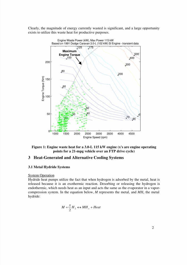
Before researching heat-generated cooling opportunities, one must first determine themagnitude of the waste heat energy available from the engine in a vehicle to see if it issignificant. The average fuel economy of a car in the US is near 21 mpg, and arepresentative vehicle could be the Ford Taurus with a 3.0-L engine and a maximumoutput power of 115 kW. Figure 1 shows that the waste heat available for a representative115-kW engine varies from 20 to 400 kW across the engine map, with an average value
over the FTP cycle of 23 kW. The temperatures of the waste heat range from 200°C
surface temperatures to 600°C gas temperatures.
Generally, the waste heat available is twice as much as the mechanical output of theengine. An engine operating at a 30% thermal efficiency is releasing the remaining 70%of the fuel energy as waste heat through the coolant, exhaust gases, and enginecompartment warm-up. During a typical drive cycle, the engine efficiency is lower thanits maximum efficiency, and as this operating efficiency decreases (e.g. 30% to 15%), themagnitude of the waste heat increases, thus representing a larger energy potential to usefor cooling via heat-generated cooling.
1
8/3/2019 Heat Cooling
http://slidepdf.com/reader/full/heat-cooling 2/15
Clearly, the magnitude of energy currently wasted is significant, and a large opportunityexists to utilize this waste heat for productive purposes.
1000 1500 2000 2500 3000 3500 4000 45000
50
100
150
200
20
30 40
50
60
70
80
90
100
125
1
175
200
300
400
500
Engine Speed (rpm)
E n g i n e
T o r q u e ( N m )
Engine Waste Power (kW), Max Power 115 kWBased on 1991 Dodge Caravan 3.0-L (102 kW) SI Engine - transient data
MaximumEngine Torque
Figure 1: Engine waste heat for a 3.0-L 115 kW engine (x's are engine operating
points for a 21-mpg vehicle over an FTP drive cycle)
3 Heat-Generated and Alternative Cooling Systems
3.1 Metal Hydride Systems
System OperationHydride heat pumps utilize the fact that when hydrogen is adsorbed by the metal, heat isreleased because it is an exothermic reaction. Desorbing or releasing the hydrogen isendothermic, which needs heat as an input and acts the same as the evaporator in a vapor-compression system. In the equation below, M represents the metal, and MH x the metalhydride:
Heat MH H x
M x +↔+ 22
2
8/3/2019 Heat Cooling
http://slidepdf.com/reader/full/heat-cooling 3/15
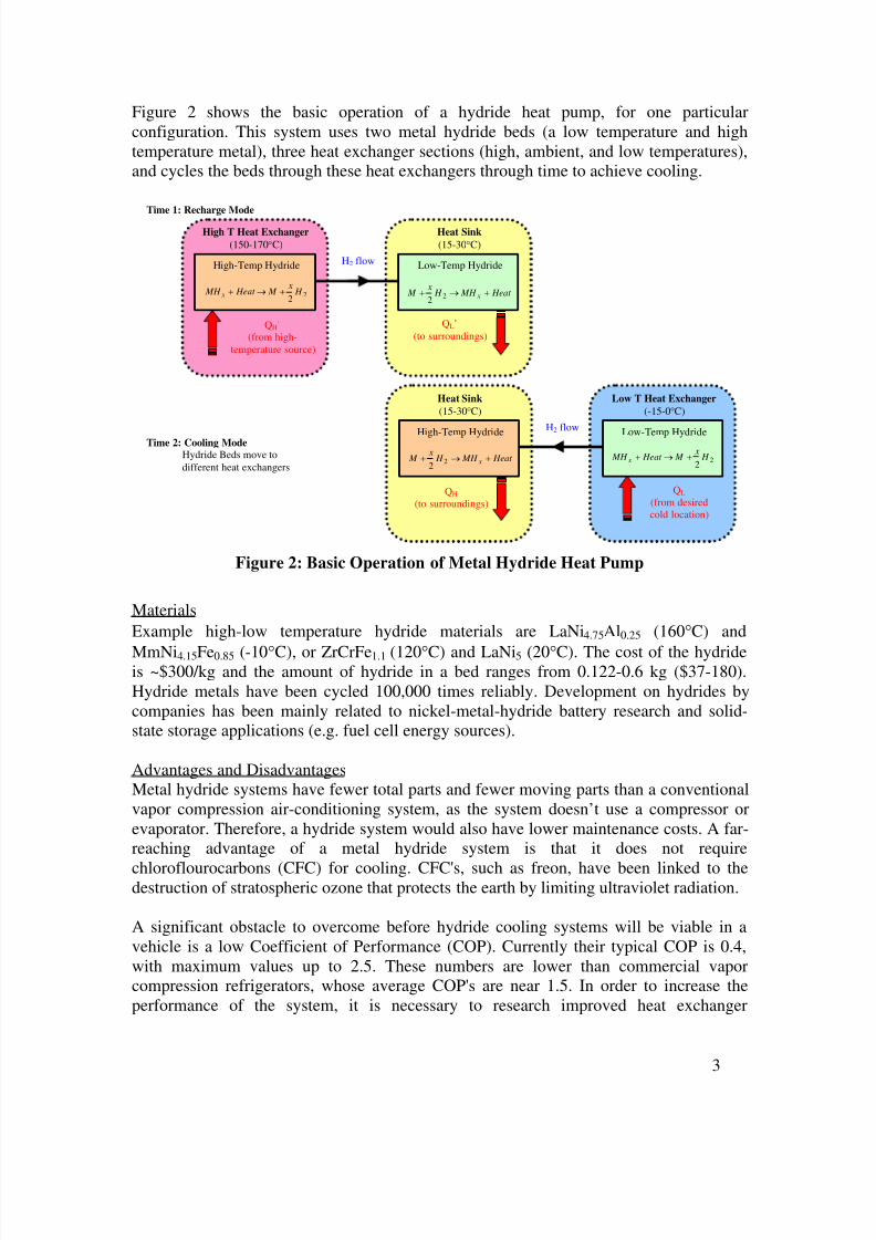
Figure 2 shows the basic operation of a hydride heat pump, for one particularconfiguration. This system uses two metal hydride beds (a low temperature and hightemperature metal), three heat exchanger sections (high, ambient, and low temperatures),and cycles the beds through these heat exchangers through time to achieve cooling.
High T Heat Exchanger
(150-170°C)
Heat Sink
(15-30°C)
QH’(from high-
temperature source)
QL’
(to surroundings)
High-Temp Hydride Low-Temp Hydride
Time 1: Recharge Mode
Time 2: Cooling ModeHydride Beds move to
different heat exchangers
H2 flow
Heat MH H x
M x +→+ 22
22
H x
M Heat MH x +→+
Heat Sink
(15-30°C)
Low T Heat Exchanger
(-15-0°C)
QH
(to surroundings)
QL
(from desiredcold location)
High-Temp Hydride Low-Temp HydrideH2 flow
Heat MH H x
M x +→+ 22
22 H
x M Heat MH x +→+
Figure 2: Basic Operation of Metal Hydride Heat Pump
Materials
Example high-low temperature hydride materials are LaNi4.75Al0.25 (160°C) and
MmNi4.15Fe0.85 (-10°C), or ZrCrFe1.1 (120°C) and LaNi5 (20°C). The cost of the hydrideis ~$300/kg and the amount of hydride in a bed ranges from 0.122-0.6 kg ($37-180).Hydride metals have been cycled 100,000 times reliably. Development on hydrides bycompanies has been mainly related to nickel-metal-hydride battery research and solid-state storage applications (e.g. fuel cell energy sources).
Advantages and DisadvantagesMetal hydride systems have fewer total parts and fewer moving parts than a conventionalvapor compression air-conditioning system, as the system doesn’t use a compressor orevaporator. Therefore, a hydride system would also have lower maintenance costs. A far-reaching advantage of a metal hydride system is that it does not require
chloroflourocarbons (CFC) for cooling. CFC's, such as freon, have been linked to thedestruction of stratospheric ozone that protects the earth by limiting ultraviolet radiation.
A significant obstacle to overcome before hydride cooling systems will be viable in avehicle is a low Coefficient of Performance (COP). Currently their typical COP is 0.4,with maximum values up to 2.5. These numbers are lower than commercial vaporcompression refrigerators, whose average COP's are near 1.5. In order to increase theperformance of the system, it is necessary to research improved heat exchanger
3
8/3/2019 Heat Cooling
http://slidepdf.com/reader/full/heat-cooling 4/15
efficiency, smaller component sizes, and system integration with the vehicle waste heat.These are all significant and challenging areas.
Past Research PerformedErgenics, based in New Jersey, created a metal hydride 5-kW AC system powered by
waste heat from simulated exhaust gases in 1992-1993. Ergenics has been awardedseveral patents surrounding their metal hydride cooling system. The system mass was 22kg and the COP was 0.33. They didn’t have strong external interest, so as a companythey’ve focused on development of metal hydrides for solid state hydrogen storage.
Thermacore, based in Pennsylvania, constructed two prototype metal hydride heat pumpsin 1997-1998 based on two Russian inventions that could significantly improve theefficiency of a hydride system. They were awarded US Patent #6,000,463 in 1999 for a“Metal Hydride Heat Pump.” Note that the following numbers are Thermacore
sensitive/proprietary numbers, for distribution only within DOE . One of the prototype
designs used self-propelled cycling, operated on a 55-minute period, cooled to -10°C,
and saw peak cooling rates of 70 W for 3-4 minutes. The second design was manuallycontrolled for a 5-minute cycle, dropping temperatures 6°C (from 22 to 16°C). Overall,the prototype heat pump was capable of producing an average of 3.4 W “cold” and a peak
of 4.5 W using 180°C heat with an average COP of 0.1 and a peak COP of 1.5 to 2.5.Thermacore is not currently funding hydride development.
Advanced Materials Corporation, a small company based in Pennsylvania, developed aprototype hydride system in 1986 for a contract for the state of Pennsylvania. Theirhydride heat pump used a pump to transfer the hydrogen and provide heating and coolingusing a different configuration than that described above. They put the system in thetrunk of a vehicle and cooled the cabin. The system had a mass of 40 kg and achieved
350 W of cooling at 16°C. They have shown interest in putting together a prototypehydride system with NREL to operate with waste heat.
Other work and modeling of hydride systems has been performed at the University of New Mexico, Albuquerque, the University of Illinois at Chicago, the University of Melbourne, Australia, and the National Academy of Sciences of Ukraine (1998-present).
3.2 Absorption Systems
System OperationAbsorption refrigeration cycles differ from vapor-compression cycles in the manner in
which compression is achieved. In the absorption cycle, the low-pressure refrigerant (e.g.ammonia or lithium bromide) vapor is absorbed in water and the liquid solution ispumped to a high pressure by a liquid pump. Figure 3 shows a schematic of the essentialelements in an absorption system. A lithium bromide absorption heat pump uses LiBr asthe working solution. The lithium bromide-based absorption chiller has been aroundcommercially since the late 1950’s and uses bromide brine with concentrations of ~60%.The ammonia-water absorption system has been around since the early 1900's.
4
8/3/2019 Heat Cooling
http://slidepdf.com/reader/full/heat-cooling 5/15
Generator Condenser
Absorber Evaporator
High Pressure
Low Pressure
High Pressure Refrigerant Vapor
ExpansionValve
QH’ (from high-temperature source) QH
(to surroundings)
QL’(to surroundings)
QL (from desiredcold location)
Pump
LiquidRefrigerant
Low Pressure Refrigerant Vapor
StrongRefrigerant
Solution
Weak Refrigerant
Solution
HeatExchanger
W
Figure 3: Schematic of Absorption Heat Pump Cycle
Advantages and DisadvantagesThe distinctive feature of the absorption system is that very little work input is requiredbecause the pumping process involves a liquid. Another advantage is that they have beenaround for a long time, such that there is a manufacturing basis for larger systems (e.g.applications for manufacturing plants, buildings).
However, a relatively high-temperature source of heat (100° to 200°C) must be availablefor the absorption system. There is more equipment in an absorption system than in a
vapor-compression system, and it can usually be economically justified only when asuitable source of heat is available that would otherwise be wasted. This is the case if vehicle waste heat is used. COP's are near 1. There may be some safety related issues intransporting ammonia or lithium bromide in vehicles, which could cause significantresistance to absorption systems in the automobile industry. Another disadvantage is thatcorrosion in the evaporator can occur. Lithium bromide, a highly corrosive brine, readilyattacks ferrous metals such as steel. The corrosion process generates hydrogen gas thatreduces the internal vacuum inside the evaporator, and the unit operates poorly. In
5
8/3/2019 Heat Cooling
http://slidepdf.com/reader/full/heat-cooling 6/15
addition, the debris resulting from the corrosion fouls narrow openings in spray headers,heat exchangers, etc.
Past Research PerformedGas Research Institute, based in Chicago Illinois is researching absorption heat pumps.
Shuangliang Teling Lithium Bromide Refrigeration Machine Co., Ltd, as implied by itsname, produces lithium bromide refrigeration systems. However, not much work hasbeen performed on integrating such a system into a vehicle.
3.3 Zeolite Systems
Zeolite systems are similar to metal hydride systems, but uses zeolite and water in theplace of a metal hydride and hydrogen. The natural mineral zeolite (e.g. porousaluminosilicate) has the property to attract (adsorb) water vapor and to incorporate it inits internal crystal lattice while releasing heat at the same time:
Heat O ZeoliteH O H Zeolite+↔+
22
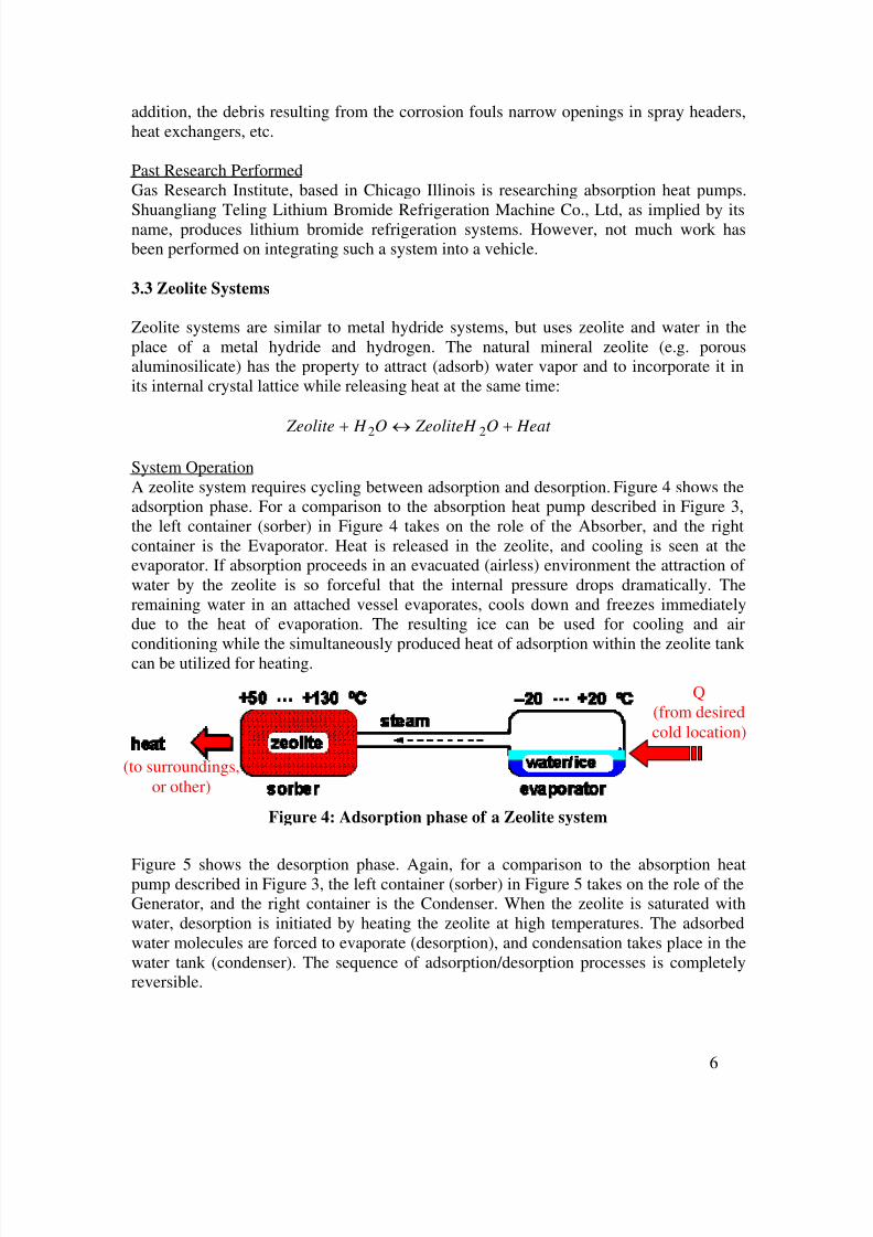
System OperationA zeolite system requires cycling between adsorption and desorption. Figure 4 shows theadsorption phase. For a comparison to the absorption heat pump described in Figure 3,the left container (sorber) in Figure 4 takes on the role of the Absorber, and the rightcontainer is the Evaporator. Heat is released in the zeolite, and cooling is seen at theevaporator. If absorption proceeds in an evacuated (airless) environment the attraction of water by the zeolite is so forceful that the internal pressure drops dramatically. Theremaining water in an attached vessel evaporates, cools down and freezes immediatelydue to the heat of evaporation. The resulting ice can be used for cooling and air
conditioning while the simultaneously produced heat of adsorption within the zeolite tank can be utilized for heating.
Q(from desiredcold location)
(to surroundings,or other)
Figure 4: Adsorption phase of a Zeolite system
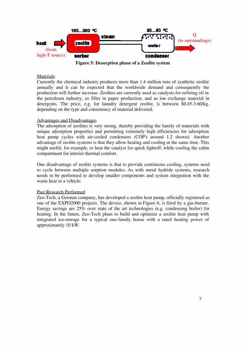
Figure 5 shows the desorption phase. Again, for a comparison to the absorption heatpump described in Figure 3, the left container (sorber) in Figure 5 takes on the role of theGenerator, and the right container is the Condenser. When the zeolite is saturated withwater, desorption is initiated by heating the zeolite at high temperatures. The adsorbedwater molecules are forced to evaporate (desorption), and condensation takes place in thewater tank (condenser). The sequence of adsorption/desorption processes is completelyreversible.
6
8/3/2019 Heat Cooling
http://slidepdf.com/reader/full/heat-cooling 7/15
Q
(to surroundings)
(fromhigh-T source)
Figure 5: Desorption phase of a Zeolite system
MaterialsCurrently the chemical industry produces more than 1.4 million tons of synthetic zeoliteannually and it can be expected that the worldwide demand and consequently theproduction will further increase. Zeolites are currently used as catalysts for refining oil inthe petroleum industry, as filler in paper production, and as ion exchange material indetergents. The price, e.g. for laundry detergent zeolite, is between $0.45-3.60/kg,depending on the type and consistency of material delivered.
Advantages and DisadvantagesThe adsorption of zeolites is very strong, thereby providing the family of materials withunique adsorption properties and permitting extremely high efficiencies for adsorptionheat pump cycles with air-cooled condensers (COP's around 1.2 shown). Anotheradvantage of zeolite systems is that they allow heating and cooling at the same time. Thismight useful, for example, to heat the catalyst for quick lightoff, while cooling the cabincompartment for interior thermal comfort.
One disadvantage of zeolite systems is that to provide continuous cooling, systems needto cycle between multiple sorption modules. As with metal hydride systems, researchneeds to be performed to develop smaller components and system integration with the
waste heat in a vehicle.
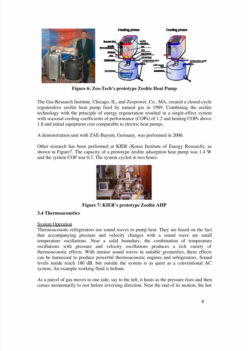
Past Research PerformedZeo-Tech, a German company, has developed a zeolite heat pump, officially registered asone of the EXPO2000 projects. The device, shown in Figure 6, is fired by a gas-burner.Energy savings are 25% over state of the art technologies (e.g. condensing boiler) forheating. In the future, Zeo-Tech plans to build and optimize a zeolite heat pump withintegrated ice-storage for a typical one-family house with a rated heating power of approximately 10 kW.
7
8/3/2019 Heat Cooling
http://slidepdf.com/reader/full/heat-cooling 8/15
Figure 6: Zeo-Tech’s prototype Zeolite Heat Pump
The Gas Research Institute, Chicago, IL, and Zeopower, Co., MA, created a closed-cycleregenerative zeolite heat pump fired by natural gas in 1989. Combining the zeolitetechnology with the principle of energy regeneration resulted in a single-effect systemwith seasonal cooling coefficients of performance (COPs) of 1.2 and heating COPs above
1.8 and initial equipment cost comparable to electric heat pumps.
A demonstration unit with ZAE-Bayern, Germany, was performed in 2000.
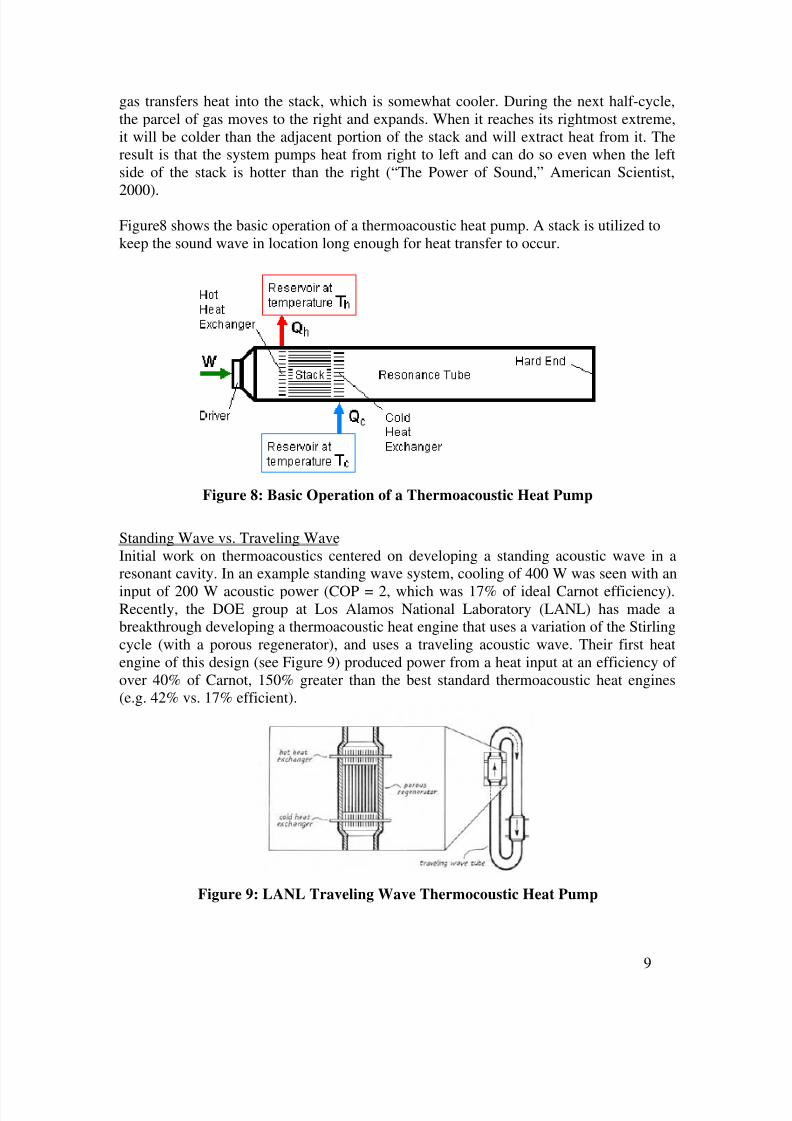
Other research has been performed at KIER (Korea Institute of Energy Research), asshown in Figure7. The capacity of a prototype zeolite adsorption heat pump was 1.4 Wand the system COP was 0.3. The system cycled in two hours.
Figure 7: KIER’s prototype Zeolite AHP
3.4 Thermoacoustics
System OperationThermoacoustic refrigerators use sound waves to pump heat. They are based on the factthat accompanying pressure and velocity changes with a sound wave are smalltemperature oscillations. Near a solid boundary, the combination of temperature
oscillations with pressure and velocity oscillations produces a rich variety of thermoacoustic effects. With intense sound waves in suitable geometries, these effectscan be harnessed to produce powerful thermoacoustic engines and refrigerators. Soundlevels inside reach 180 dB, but outside the system is as quiet as a conventional ACsystem. An example working fluid is helium.
As a parcel of gas moves to one side, say to the left, it heats as the pressure rises and thencomes momentarily to rest before reversing direction. Near the end of its motion, the hot
8
8/3/2019 Heat Cooling
http://slidepdf.com/reader/full/heat-cooling 9/15
gas transfers heat into the stack, which is somewhat cooler. During the next half-cycle,the parcel of gas moves to the right and expands. When it reaches its rightmost extreme,it will be colder than the adjacent portion of the stack and will extract heat from it. Theresult is that the system pumps heat from right to left and can do so even when the leftside of the stack is hotter than the right (“The Power of Sound,” American Scientist,
2000).
Figure8 shows the basic operation of a thermoacoustic heat pump. A stack is utilized tokeep the sound wave in location long enough for heat transfer to occur.
Figure 8: Basic Operation of a Thermoacoustic Heat Pump
Standing Wave vs. Traveling WaveInitial work on thermoacoustics centered on developing a standing acoustic wave in aresonant cavity. In an example standing wave system, cooling of 400 W was seen with an
input of 200 W acoustic power (COP = 2, which was 17% of ideal Carnot efficiency).Recently, the DOE group at Los Alamos National Laboratory (LANL) has made abreakthrough developing a thermoacoustic heat engine that uses a variation of the Stirlingcycle (with a porous regenerator), and uses a traveling acoustic wave. Their first heatengine of this design (see Figure 9) produced power from a heat input at an efficiency of over 40% of Carnot, 150% greater than the best standard thermoacoustic heat engines(e.g. 42% vs. 17% efficient).
Advantages and DisadvantagesThermoacoustic systems appear attractive because of their elegance, reliability, and lowcost, in spite of only modest efficiency. They are environmentally safe and have nosliding parts. This difference makes thermoacoustic devices much simpler and potentially
much more reliable than conventional engines and refrigerators, because they can avoidwear associated with valves, piston rings, crankshafts, connecting rods and so forth. Thusthermoacoustic devices require no lubrication.
Disadvantages of thermoacoustic systems are low efficiency and low power density.Research is predicted to give efficiencies comparable to vapor-compression refrigerators.Another significant disadvantage of thermoacoustic systems is their typically large size.Also, thermoacoustic devices are very sensitive devices—if the standing or travelingwave gets out of phase for any reason (e.g. dirty heat exchangers, shock or vibration), thecooling can be disrupted. Today, thermoacoustic refrigerators are used in special
applications and temperature changes of 25°C have been achieved. More research is
needed in order to get commercially marketable devices, in particular research to focuson heat exchanger design, transducer design, sizing, robustness, and increasing overallefficiency and decreasing price.
Past Research PerformedA qualitatively accurate theory was developed in the 1970s and the first thermoacousticrefrigerator was built in 1985. Hence, this technique is relatively new. So far, mostmachines of this variety reside in laboratories. But prototype thermoacoustic refrigeratorshave operated on the Space Shuttle and aboard a Navy warship (cooling radarelectronics).
Most of the work related to thermoacoustics has been performed at LANL (funded by theDOE's Office of Basic Energy Sciences), Penn State University, and the Navalpostgraduate school (CA), with additional work at the University of Utah, and ChalmersUniversity of Technology. The First International Workshop on Thermoacoustics washeld in 2001 in the Netherlands with 80 attendees. The workshop showed that anunderstanding of combustion oscillations by thermoacoustics is on its way, and numericalsimulations are in reasonable agreement with experiments. LANL's numerical simulationtool is named DeltaE (Design Environment for Low-amplitude Thermoacoustic Engines).
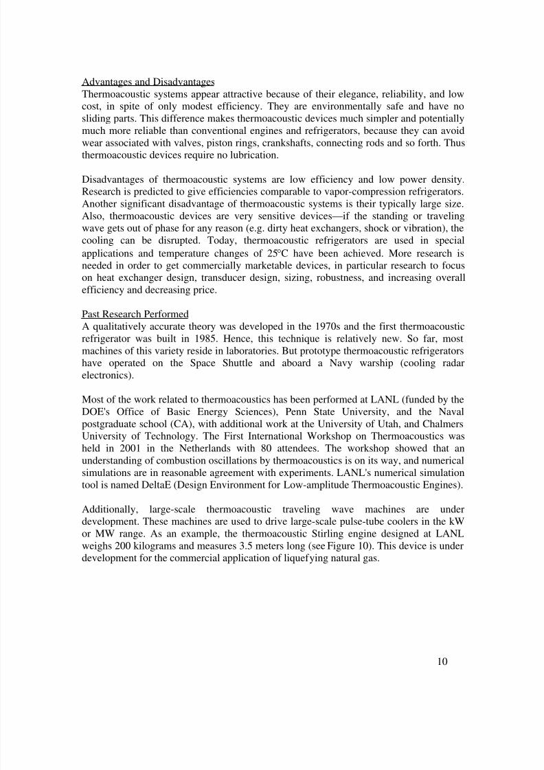
Additionally, large-scale thermoacoustic traveling wave machines are underdevelopment. These machines are used to drive large-scale pulse-tube coolers in the kWor MW range. As an example, the thermoacoustic Stirling engine designed at LANLweighs 200 kilograms and measures 3.5 meters long (see Figure 10). This device is underdevelopment for the commercial application of liquefying natural gas.
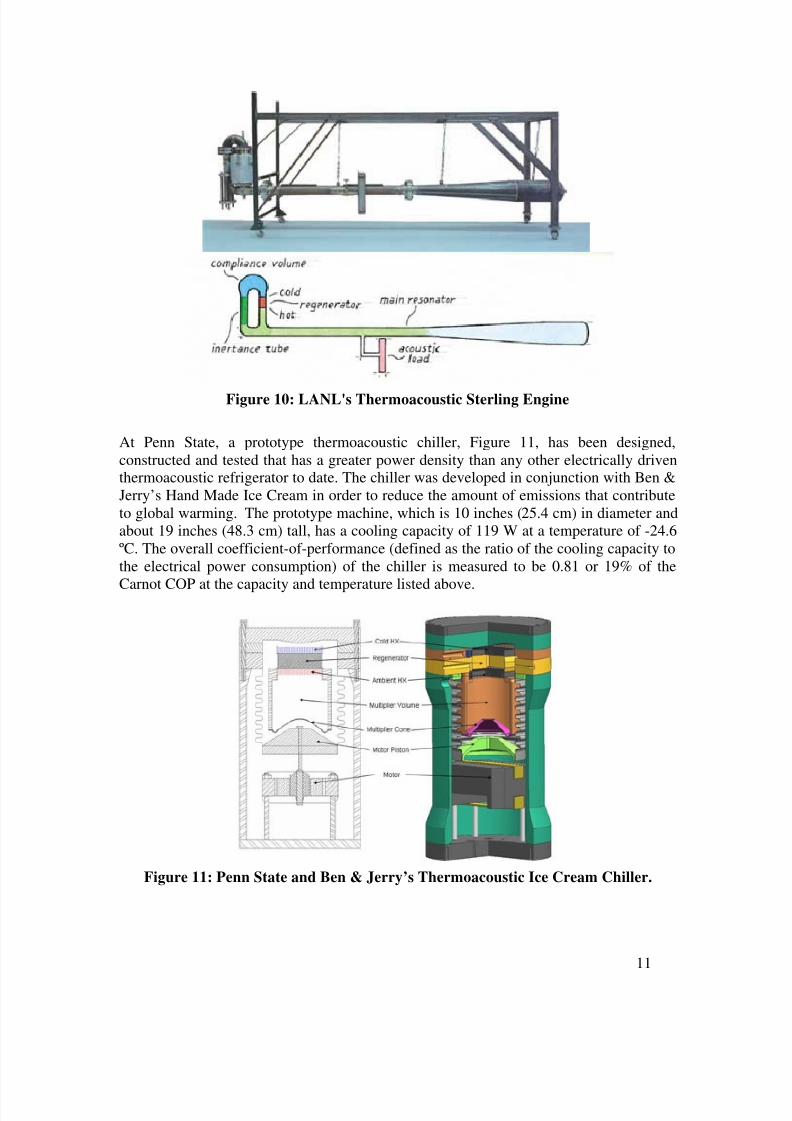
At Penn State, a prototype thermoacoustic chiller, Figure 11, has been designed,constructed and tested that has a greater power density than any other electrically driventhermoacoustic refrigerator to date. The chiller was developed in conjunction with Ben &Jerry’s Hand Made Ice Cream in order to reduce the amount of emissions that contributeto global warming. The prototype machine, which is 10 inches (25.4 cm) in diameter andabout 19 inches (48.3 cm) tall, has a cooling capacity of 119 W at a temperature of -24.6ºC. The overall coefficient-of-performance (defined as the ratio of the cooling capacity tothe electrical power consumption) of the chiller is measured to be 0.81 or 19% of the
Carnot COP at the capacity and temperature listed above.
Figure 11: Penn State and Ben & Jerry’s Thermoacoustic Ice Cream Chiller.
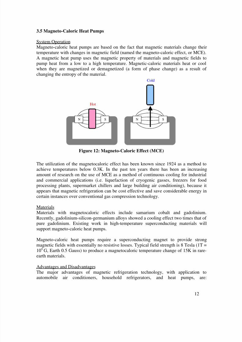
System OperationMagneto-caloric heat pumps are based on the fact that magnetic materials change theirtemperature with changes in magnetic field (named the magneto-caloric effect, or MCE).
A magnetic heat pump uses the magnetic property of materials and magnetic fields topump heat from a low to a high temperature. Magnetic-caloric materials heat or coolwhen they are magnetized or demagnetized (a form of phase change) as a result of changing the entropy of the material.
Hot
SN
Cold
SN
Figure 12: Magneto-Caloric Effect (MCE)
The utilization of the magnetocaloric effect has been known since 1924 as a method toachieve temperatures below 0.3K. In the past ten years there has been an increasingamount of research on the use of MCE as a method of continuous cooling for industrial
and commercial applications (i.e. liquefaction of cryogenic gasses, freezers for foodprocessing plants, supermarket chillers and large building air conditioning), because itappears that magnetic refrigeration can be cost effective and save considerable energy incertain instances over conventional gas compression technology.
MaterialsMaterials with magnetocaloric effects include samarium cobalt and gadolinium.Recently, gadolinium-silicon-germanium alloys showed a cooling effect two times that of pure gadolinium. Existing work in high-temperature superconducting materials willsupport magneto-caloric heat pumps.
Magneto-caloric heat pumps require a superconducting magnet to provide strongmagnetic fields with essentially no resistive losses. Typical field strength is 8 Tesla (1T =104
G, Earth 0.5 Gauss) to produce a magnetocaloric temperature change of 15K in rare-earth materials.
Advantages and DisadvantagesThe major advantages of magnetic refrigeration technology, with application toautomobile air conditioners, household refrigerators, and heat pumps, are:
environmentally friendly, high energy-conversion efficiency—potentially high due to thehigh reversibility of the magneto-caloric effect, and energy-savings as there is nocompressor required. There is also a potentially dramatic reduction in the complexity,size and mass of the cooling unit.
However, magnetic freezing technology was previously considered impractical for airconditioners, refrigerators and other electric appliances because a single change in amagnetic field yields only minimal change in the temperature of a magnetic material.Magneto-caloric cooling currently produces only minimal cooling (e.g. 300 W), whichwould be insufficient for cooling an automobile (4 kW). Another disadvantage is thematerial costs and high capital costs due to the need for magnetic shielding, especially invehicles. This could limit the technology to niche markets. The weight of magneto-caloric systems could also be a disadvantage in terms of fuel economy impacts of movingmass.
Past Research Performed
As a CARAT project in 1998-1999, Iowa State University performed research on"Development of Vehicle Magnetic Air Conditioning Technology." They collaboratedwith the Astronautics Corporation of America on the project. Their results indicated thatpersonal cooling (<1 kW) was more viable than an overall air conditioner system (3-6kW). They saw changes in temperature of 4K with a 2 Tesla magnetic field, and up to13K with a 10 T field.
In October 2000, in cooperation with Toshiba Corp, Chubu Electric Power Co. developed
the world's first magnetic freezing system. They reduced the temperature from 28°C to -
1°C using gadolinium (Gd) as a magnetic material. The system demonstrated a COP of 4.3.
With funding from the EPA, the National Center for Environmental Research at GeorgeWashington University currently has a $250K grant through 2003 for "Preparation of Superferromagnetic Lanthanide Nanoparticulate Magnetic Refrigerants." This researchlooks at magnetic nanocomposites instead of either paramagnetic or ferromagneticmaterials for magnetic cooling at ambient temperatures.
3.6 Ejector Refrigeration
System OperationEjector refrigeration cycles differ from vapor-compression cycles in the manner in which
compression is achieved. In the ejector cycle, the low-pressure refrigerant (e.g. water) isdriven by fluid kinetic or thermal energy as opposed to pumps or compressors which aredriven by mechanical energy. Figure 13 shows a schematic of the essential elements in anejector system. The waste heat from the exhaust would be utilized to convert water tosuper heated steam. The steam would then be utilized by a steady-stream ejector orturbomachinery to compress a secondary water stream.
Figure13: Schematic of Ejector Refrigeration Cycle
Advantages and DisadvantagesThe ejector refrigeration cycle has the distinct advantage of being environmentallyfriendly when water is used as the working fluid – other refrigerants can be used in thecycle. Like the absorption system, the ejector refrigeration cycle requires very little work input because the pumping process involves a liquid.
The ejector can either be a steady-flow ejector or can be replaced by a turbine-compressor. Steady-flow ejector’s have been in development over the past century and
are unlikely to attain COP’s greater than 0.2. Turbine ejector’s have the potential forgreater COP’s but such a system would be expensive and require large components if water were used as a refrigerant. (Garris, C., et al, “A New Thermally DrivenRefrigeration System with Environmental Benefits”, 33rd Intersociety EngineeringConference on Energy Conversion, 1998) Furthermore, turbomachinery is somewhatunforgiving with regards to sealing and bearing requirements considering the rotationalspeed of the turbine, upwards of 75,000 rpm. Research is on-going and it is hoped thatwithin the next several years the performance of turbomachinery will demonstrateimprovements over steady-state flow ejectors.
Past Research Performed
The University of Nottingham has been at the forefront of the development of micro-combined heat and power (CHP) systems using renewable energy for a number of years.The main achievement has been the development of a micro-CHP system that is capableof producing electricity, heating and cooling from the same cycle and the demonstrationof this cycle. The Rankine cycle has a 1.5kW electrical output and operates with anefficiency of 4% and the ejector cooling cycle has a 3kW cooling effect at a COP of 0.35.The system has been shown to provide a performance competitive with other methods of
electricity generation, heating and cooling in terms of emissions. The system (Figure 14)would be ideal for remote applications, as it is relatively compact.
Figure 14: University of Nottingham ejector cooling system capable of heating, cooling,and electrical power generation.
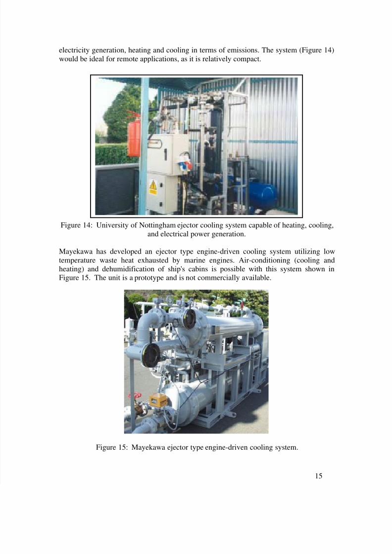
Mayekawa has developed an ejector type engine-driven cooling system utilizing lowtemperature waste heat exhausted by marine engines. Air-conditioning (cooling andheating) and dehumidification of ship's cabins is possible with this system shown inFigure 15. The unit is a prototype and is not commercially available.
Figure 15: Mayekawa ejector type engine-driven cooling system.