Page 1
Heat Exchanger Thermal Design Shell&Tube V7.3.1 CP1Page 1
File: VELIKA MRCINA OD IZMJENJIVAČA TOPLINE.EDRDate: 24.2.2015. Time: 12:44:27
Description
IZMJENJIVAČ TOPLINE DIMNI PLINOVI IZGARANJA - VODA
Heading
Remarks
Application Options
Gas, no phase change
Set default
Liquid, no phase change
Set default
Tube side
Rating / Checking
Set default
Set default
SI
Set default
Advanced method
Application
Condenser type
Application
Vaporizer type
Location of hot fluid
Calculation mode
Simulation calculation
Simulation calculation
Select geometry based on this dimensional standard
Thermosiphon circuit calculation
Calculation Method
Process Data
0,8203 2,8133
950 115 15 90
0,993 0,793 2,5 2,2
0,2 0,5
0,0002 0,0004
kg/s
°C
bar
bar
m˛ K/W
Heat load Heat load
kW
1 1 0 0
bar
0,2 0,3bar
DIMNI PLINOVI VODA
Mass flow rate (total)
Temperature
Operating pressure (absolute)
Allowable pressure drop
Fouling resistance
Hot Side Cold Side
Heat exchanged
Heat Load Balance Options
In OutIn Out
Vapor mass fraction
Pressure at liquid surface in column
Estimated pressure drop
Fluid name
Page 2
Heat Exchanger Thermal Design Shell&Tube V7.3.1 CP1Page 2
File: VELIKA MRCINA OD IZMJENJIVAČA TOPLINE.EDRDate: 24.2.2015. Time: 12:44:29
Hot Side Databank
COMThermo
Mole flowrate or %
Pressures
bar
0,993
0,793
BL1(273)
BL1(313)
BL1(314)
Vapor-Liquid-Liquid
Hot side composition specification
Aspen Plus or Aspen Properties run file
Physical property package
Aspen property method
Aspen free-water method
Aspen water solubility
Aspen flash option
Hot Side - Component
ComThermo Components Composition Component type
CO2 49,43 Program
SO2 0,07 Program
NO2 0,05 Program
Oxygen 13,52 Program
Water 36,93 Program
Hot Side - Stream Properties
Temperature Specificenthalpy
Vapor massfraction
°C kJ/kg
950 -7441,3 1
910 -7500,7 1
870 -7559,7 1
831 -7616,7 1
791 -7674,8 1
751 -7732,2 1
711 -7789,2 1
672 -7844,2 1
632 -7900 1
592 -7955,2 1
552 -8009,7 1
513 -8062,2 1
473 -8115,3 1
433 -8167,7 1
393 -8219,4 1
354 -8269 1
314 -8319 1
274 -8368,2 1
234 -8416,5 1
195 -8462,8 1
155 -8509,5 1
115 -8555,2 1
Page 3
Heat Exchanger Thermal Design Shell&Tube V7.3.1 CP1Page 3
File: VELIKA MRCINA OD IZMJENJIVAČA TOPLINE.EDRDate: 24.2.2015. Time: 12:44:29
Hot Side - Stream Properties
Temperature Specificenthalpy
Vapor massfraction
°C kJ/kg
950 -7441,3 1
910 -7500,7 1
870 -7559,7 1
831 -7616,7 1
791 -7674,7 1
751 -7732,2 1
711 -7789,2 1
672 -7844,2 1
632 -7900 1
592 -7955,1 1
552 -8009,6 1
513 -8062,1 1
473 -8115,3 1
433 -8167,7 1
393 -8219,3 1
354 -8268,9 1
314 -8318,9 1
274 -8368,1 1
234 -8416,4 1
195 -8462,7 1
155 -8509,3 1
115 -8555 1
Hot Side - Liquid Properties
TemperatureLiquid specificheat
Liquid thermalcond.
Liquidviscosity
Liquiddensity
Liquid surfacetension
°C kJ/(kg K) W/(m K) mPa s kg/mł N/m
950
910
870
831
791
751
711
672
632
592
552
513
473
433
393
354
314
274
234
195
155
115
Page 4
Heat Exchanger Thermal Design Shell&Tube V7.3.1 CP1Page 4
File: VELIKA MRCINA OD IZMJENJIVAČA TOPLINE.EDRDate: 24.2.2015. Time: 12:44:30
Hot Side - Liquid Properties
TemperatureLiquid specificheat
Liquid thermalcond.
Liquidviscosity
Liquiddensity
Liquid surfacetension
°C kJ/(kg K) W/(m K) mPa s kg/mł N/m
950
910
870
831
791
751
711
672
632
592
552
513
473
433
393
354
314
274
234
195
155
115
Hot Side - Vapor Properties
TemperatureVapor specificheat
Vapor thermalcond.
Vaporviscosity
Vapor density Vaporweight
°C kJ/(kg K) W/(m K) mPa s kg/mł
950 1,492 0,0859 0,0458 0,32 32,8
910 1,48 0,0842 0,0448 0,33 32,8
870 1,469 0,0823 0,0437 0,34 32,8
831 1,457 0,0803 0,0426 0,35 32,8
791 1,444 0,0781 0,0415 0,37 32,8
751 1,431 0,0757 0,0404 0,38 32,8
711 1,417 0,0731 0,0393 0,4 32,8
672 1,403 0,0705 0,0382 0,41 32,8
632 1,387 0,0677 0,037 0,43 32,8
592 1,371 0,0648 0,0358 0,45 32,8
552 1,355 0,0617 0,0346 0,47 32,8
513 1,338 0,0587 0,0333 0,5 32,8
473 1,319 0,0555 0,0318 0,53 32,8
433 1,301 0,0523 0,03 0,55 32,8
393 1,281 0,0489 0,0282 0,59 32,8
354 1,261 0,0457 0,0264 0,63 32,8
314 1,241 0,0423 0,0246 0,67 32,8
274 1,219 0,0389 0,0227 0,72 32,8
234 1,198 0,0356 0,0208 0,77 32,8
195 1,177 0,0323 0,019 0,84 32,8
155 1,155 0,029 0,0172 0,92 32,8
115 1,133 0,0257 0,0153 1,01 32,8
Page 5
Heat Exchanger Thermal Design Shell&Tube V7.3.1 CP1Page 5
File: VELIKA MRCINA OD IZMJENJIVAČA TOPLINE.EDRDate: 24.2.2015. Time: 12:44:31
Hot Side - Vapor Properties
TemperatureVapor specificheat
Vapor thermalcond.
Vaporviscosity
Vapor density Vaporweight
°C kJ/(kg K) W/(m K) mPa s kg/mł
950 1,492 0,0859 0,0458 0,26 32,8
910 1,48 0,0842 0,0448 0,26 32,8
870 1,468 0,0823 0,0437 0,27 32,8
831 1,457 0,0803 0,0426 0,28 32,8
791 1,444 0,0781 0,0415 0,29 32,8
751 1,431 0,0757 0,0404 0,31 32,8
711 1,417 0,0731 0,0393 0,32 32,8
672 1,403 0,0705 0,0382 0,33 32,8
632 1,387 0,0677 0,037 0,35 32,8
592 1,371 0,0648 0,0358 0,36 32,8
552 1,355 0,0617 0,0346 0,38 32,8
513 1,337 0,0587 0,0333 0,4 32,8
473 1,319 0,0555 0,0318 0,42 32,8
433 1,3 0,0522 0,03 0,44 32,8
393 1,281 0,0489 0,0282 0,47 32,8
354 1,261 0,0457 0,0264 0,5 32,8
314 1,24 0,0423 0,0246 0,53 32,8
274 1,219 0,0389 0,0227 0,57 32,8
234 1,197 0,0356 0,0208 0,62 32,8
195 1,176 0,0323 0,019 0,67 32,8
155 1,154 0,029 0,0172 0,73 32,8
115 1,132 0,0257 0,0153 0,81 32,8
Hot Side - 2-Phase liquid
Temperature Liquid 2heat
Liquid 2cond.
Liquid 2viscosity
Liquiddensity
Liquid 2tension
°C kJ/(kg K) W/(m K) mPa s kg/mł N/m
950
910
870
831
791
751
711
672
632
592
552
513
473
433
393
354
314
274
234
195
155
115
Page 6
Heat Exchanger Thermal Design Shell&Tube V7.3.1 CP1Page 6
File: VELIKA MRCINA OD IZMJENJIVAČA TOPLINE.EDRDate: 24.2.2015. Time: 12:44:32
Hot Side - 2-Phase liquid
Temperature Liquid 2heat
Liquid 2cond.
Liquid 2viscosity
Liquiddensity
Liquid 2tension
°C kJ/(kg K) W/(m K) mPa s kg/mł N/m
950
910
870
831
791
751
711
672
632
592
552
513
473
433
393
354
314
274
234
195
155
115
Page 7
Heat Exchanger Thermal Design Shell&Tube V7.3.1 CP1Page 7
File: VELIKA MRCINA OD IZMJENJIVAČA TOPLINE.EDRDate: 24.2.2015. Time: 12:44:32
Cold Side Databank
COMThermo
Mole flowrate or %
Pressures
bar
2,5
2,2
BL1(316)
BL1(317)
BL1(318)
Vapor-Liquid-Liquid
Aspen Plus or Aspen Properties run file
Cold side composition specification
Physical property package
Aspen flash option
Aspen water solubility
Aspen free-water method
Aspen property method
Cold Side - Component
ComThermo Components Composition Component type
Water 100 Program
Cold Side - Stream Properties
Temperature Specificenthalpy
Vapor massfraction
°C kJ/kg
15 -15885,6 0
20 -15864,1 0
25 -15842,5 0
30 -15820,9 0
35 -15799,4 0
40 -15777,8 0
45 -15756,2 0
50 -15734,6 0
55 -15713 0
60 -15691,4 0
65 -15669,7 0
70 -15648 0
75 -15626,3 0
80 -15604,5 0
85 -15582,7 0
90 -15560,9 0
Page 8
Heat Exchanger Thermal Design Shell&Tube V7.3.1 CP1Page 8
File: VELIKA MRCINA OD IZMJENJIVAČA TOPLINE.EDRDate: 24.2.2015. Time: 12:44:32
Cold Side - Stream Properties
Temperature Specificenthalpy
Vapor massfraction
°C kJ/kg
15 -15885,7 0
20 -15864,1 0
25 -15842,5 0
30 -15821 0
35 -15799,4 0
40 -15777,8 0
45 -15756,2 0
50 -15734,6 0
55 -15713 0
60 -15691,4 0
65 -15669,7 0
70 -15648 0
75 -15626,3 0
80 -15604,6 0
85 -15582,7 0
90 -15560,9 0
Cold Side - Liquid Properties
TemperatureLiquid specificheat
Liquid thermalcond.
Liquidviscosity
Liquiddensity
Liquid surfacetension
°C kJ/(kg K) W/(m K) mPa s kg/mł N/m
15 4,316 0,5965 1,136 999,01 0,0738
20 4,314 0,6041 1,0017 998,12 0,073
25 4,313 0,6114 0,8904 996,96 0,0721
30 4,313 0,6184 0,7972 995,55 0,0712
35 4,314 0,6251 0,7185 993,92 0,0704
40 4,316 0,6315 0,6514 992,09 0,0695
45 4,318 0,6375 0,5939 990,06 0,0686
50 4,321 0,6432 0,5442 987,87 0,0677
55 4,325 0,6486 0,5009 985,5 0,0668
60 4,33 0,6537 0,4631 982,98 0,066
65 4,335 0,6584 0,4298 980,31 0,0651
70 4,341 0,6629 0,4004 977,49 0,0642
75 4,348 0,667 0,3743 974,54 0,0633
80 4,357 0,6708 0,351 971,46 0,0623
85 4,365 0,6743 0,3301 968,26 0,0614
90 4,375 0,6774 0,3113 964,93 0,0605
Page 9
Heat Exchanger Thermal Design Shell&Tube V7.3.1 CP1Page 9
File: VELIKA MRCINA OD IZMJENJIVAČA TOPLINE.EDRDate: 24.2.2015. Time: 12:44:33
Cold Side - Liquid Properties
TemperatureLiquid specificheat
Liquid thermalcond.
Liquidviscosity
Liquiddensity
Liquid surfacetension
°C kJ/(kg K) W/(m K) mPa s kg/mł N/m
15 4,316 0,5965 1,136 999 0,0738
20 4,314 0,6041 1,0017 998,11 0,073
25 4,313 0,6114 0,8904 996,94 0,0721
30 4,313 0,6184 0,7972 995,53 0,0712
35 4,314 0,6251 0,7185 993,91 0,0704
40 4,316 0,6315 0,6514 992,07 0,0695
45 4,318 0,6375 0,5939 990,05 0,0686
50 4,321 0,6432 0,5442 987,85 0,0677
55 4,325 0,6486 0,5009 985,49 0,0668
60 4,33 0,6537 0,4631 982,97 0,066
65 4,335 0,6584 0,4298 980,29 0,0651
70 4,342 0,6629 0,4004 977,48 0,0642
75 4,349 0,667 0,3743 974,53 0,0633
80 4,357 0,6708 0,351 971,45 0,0623
85 4,366 0,6743 0,3301 968,25 0,0614
90 4,375 0,6774 0,3113 964,92 0,0605
Cold Side - Vapor Properties
TemperatureVapor specificheat
Vapor thermalcond.
Vaporviscosity
Vapor density Vaporweight
Diffusivity
°C kJ/(kg K) W/(m K) mPa s kg/mł m˛/s
15
20
25
30
35
40
45
50
55
60
65
70
75
80
85
90
Page 10
Heat Exchanger Thermal Design Shell&Tube V7.3.1 CP1Page 10
File: VELIKA MRCINA OD IZMJENJIVAČA TOPLINE.EDRDate: 24.2.2015. Time: 12:44:34
Cold Side - Vapor Properties
TemperatureVapor specificheat
Vapor thermalcond.
Vaporviscosity
Vapor density Vaporweight
Diffusivity
°C kJ/(kg K) W/(m K) mPa s kg/mł m˛/s
15
20
25
30
35
40
45
50
55
60
65
70
75
80
85
90
Cold Side - 2-Phase liquid
Temperature Liquid 2heat
Liquid 2cond.
Liquid 2viscosity
Liquiddensity
Liquid 2tension
°C kJ/(kg K) W/(m K) mPa s kg/mł N/m
15
20
25
30
35
40
45
50
55
60
65
70
75
80
85
90
Page 11
Heat Exchanger Thermal Design Shell&Tube V7.3.1 CP1Page 11
File: VELIKA MRCINA OD IZMJENJIVAČA TOPLINE.EDRDate: 24.2.2015. Time: 12:44:34
Cold Side - 2-Phase liquid
Temperature Liquid 2heat
Liquid 2cond.
Liquid 2viscosity
Liquiddensity
Liquid 2tension
°C kJ/(kg K) W/(m K) mPa s kg/mł N/m
15
20
25
30
35
40
45
50
55
60
65
70
75
80
85
90
Page 12
Heat Exchanger Thermal Design Shell&Tube V7.3.1 CP1Page 12
File: VELIKA MRCINA OD IZMJENJIVAČA TOPLINE.EDRDate: 24.2.2015. Time: 12:44:34
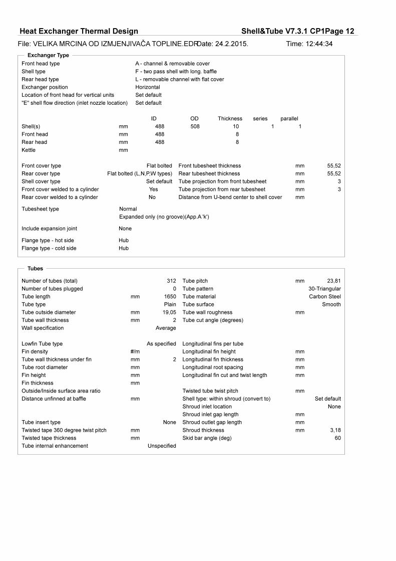
Exchanger Type
Normal
Expanded only (no groove)(App.A 'k')
None
A - channel & removable cover
F - two pass shell with long. baffle
L - removable channel with flat cover
Horizontal
Flat bolted
Yes
Flat bolted (L,N,P,W types)
No
Set default
Hub
Hub
Set default
Set default
488 508mm
mm
mm
mm
488
488
10 1 1
mm
55,52
55,52
mm
mm
3
3
mm
mm
8
8
Flange type - cold side
Flange type - hot side
Include expansion joint
Tubesheet type
Shell cover type
Rear cover welded to a cylinder
Rear cover type
Front cover welded to a cylinder
Front cover type
Exchanger position
Rear head type
Shell type
Front head type
Location of front head for vertical units
"E" shell flow direction (inlet nozzle location)
Shell(s)
Front head
Rear head
Kettle
ODID Thickness series parallel
Distance from U-bend center to shell cover
Front tubesheet thickness
Rear tubesheet thickness
Tube projection from front tubesheet
Tube projection from rear tubesheet
Tubes
mm
Plain
19,05
2
Average
30-Triangular
23,81
mm
mm
mm
mm
#/m
mm
mm
312
0
mm 1650 Carbon Steel
Smooth
As specified
2mm
mm
mm
mm
mm
mm
None
mm
mm
mm
Set default
None
mm
mm
3,18mm
60
UnspecifiedTube internal enhancement
Tube wall roughness
Twisted tape 360 degree twist pitch
Outside/Inside surface area ratio
Fin density
Fin thickness
Fin height
Tube pitch
Tube pattern
Wall specification
Tube wall thickness
Tube outside diameter
Tube type
Number of tubes (total)
Number of tubes plugged
Tube length Tube material
Tube surface
Tube cut angle (degrees)
Lowfin Tube type
Tube wall thickness under fin
Tube root diameter
Distance unfinned at baffle
Longitudinal fins per tube
Longitudinal fin height
Longitudinal fin thickness
Longitudinal root spacing
Tube insert type
Twisted tape thickness
Longitudinal fin cut and twist length
Twisted tube twist pitch
Shell type: within shroud (convert to)
Shroud inlet location
Shroud inlet gap length
Shroud outlet gap length
Shroud thickness
Skid bar angle (deg)
Page 13
Heat Exchanger Thermal Design Shell&Tube V7.3.1 CP1Page 13
File: VELIKA MRCINA OD IZMJENJIVAČA TOPLINE.EDRDate: 24.2.2015. Time: 12:44:35
Baffles
Single segmental
41,55
Vertical
mm
Yes
9,52mm
685mm
2
423,98mm
482,5mm
mm
mm
mm
4,76mm
0,4mm
no
no
mm
mm
mm
mm
9,52mm
0
Set default
mm
0
YesAlign baffle cut with tubes
Support/baffle to tangent of U-bend distance
Baffle cut orientation
Baffle cut (% of diam.) outer
Baffle type
Tubes are in baffle window
Baffle thickness
Baffle spacing center-center
Number of baffles
Baffle spacing at inlet
End length at front head (tube end to closest baffle)
End length at rear head (tube end to closest baffle)
Distance between baffles at central in/out for G,H,I,J shells
Distance between baffles at center of H shell
Baffle OD to shell ID diametric clearance
Baffle tube hole to tube OD diametric clearance
Special inlet nozzle support
Support or blanking baffle at rear end
Length of tube beyond support/blanking baffle
Number of extra supports for U-bends
Number of supports at center of H shell
Number of supports at inlet/outlet for G, H, I, J shells
Number of supports between central baffles
Number of supports at front head end space
Number of supports at rear head end space
Window length at rear head for F, G, H shells
Window length at front head for G, H shells
Window length at center for H shells
Baffle thickness
Percent leakage across longitudinal baffle
Multi-segmental baffle starting baffle
Longitudinal Baffle
Number of supports for K, X shells
Deresonating Baffles
Number of deresonating baffles
Largest deresonating baffle-baffle or baffle-shell distance
Baffles
Number of baffle spaces
Baffle spacing mm
Baffle cut percent, outer
Baffle cut percent, inner
Baffle cut percent,intermediate
One regionNumber of regions for variable baffle pitch
Variable baffle pitch: First to last pitch ratio
Page 14
Heat Exchanger Thermal Design Shell&Tube V7.3.1 CP1Page 14
File: VELIKA MRCINA OD IZMJENJIVAČA TOPLINE.EDRDate: 24.2.2015. Time: 12:44:35
Bundle
Use Layout value (warning)
14,66
14,66
Standard symmetry
1
mm
mm
mm
9,55mm
15,88mm
Use existing layout
Quadrant (dbl.band)
Normal bundle
30-Triangular
23,81mm
2
Vertical
Undefined
7,63mm
7,63mm
11,11mm
476,89mm
15,78mm
mm
1
0
Unaligned
Main input / Tube layout inconsistencies
Open distance at top of layout
Open distance at bottom of layout
Tube layout symmetry
Number of tie rods
Number of sealing strip pairs
Minimum U-bend diameter
Tie rod diameter
Spacer diameter
Tube layout option
Pass layout
Tube layout design
Tube pattern
Tube pitch
Tube passes
Pass layout orientation
Orientation of U-bends
Open distance on left side of layout
Open distance on right side of layout
Shell ID to outer tube limit diametric clearance
Outer tube limit diameter
Horizontal pass partition width
Vertical pass partition width
Number of horizontal pass partition lanes
Number of vertical pass partition lanes
Cleaning lane or tube alignment
Page 15
Heat Exchanger Thermal Design Shell&Tube V7.3.1 CP1Page 15
File: VELIKA MRCINA OD IZMJENJIVAČA TOPLINE.EDRDate: 24.2.2015. Time: 12:44:35
Nozzles
-
Slip on Slip on
-
no
no
NozSizeSS
Nominal diameter mm
Actual OD mm 60,3 48,3
Actual ID mm 52,3 41,1
Wall thickness mm 4 3,6
Nozzle orientation Bottom Top
Distance to front tubesheet mm
Number of nozzles 1 1
Multiple nozzle spacing mm
Nozzle / Impingement type No impingement No impingement
Remove tubes below nozzle Equate areas Equate areas
Maximum nozzle RhoV2 kg/(ms˛)Nozzle ignore options
NozSizeTS
Nominal diameter mm
Actual OD mm 219,1 139,7
Actual ID mm 203,1 125,5
Wall thickness mm 8 7,1
Nozzle orientation Top Bottom
Distance to tubesheet mm
Centerline offset distance mm
Maximum nozzle RhoV2 kg/(ms˛)Nozzle ignore options
Dome OD mm
Vapor belt diametric clearance mm
Vapor belt slot area m˛
Vapor belt axial length mm
unspecified
Set default
ID
Shell side nozzle flange rating
Shell side nozzle flange type
Shell Side Tube Side
Use separate outlet nozzles for hot side liquid/vapor flows
Use separate outlet nozzles for cold side liquid/vapor flows
Shell Side
Tube Side
Shell side nozzle location options
Location of nozzle at U-bend
Nozzle diameter displayed on TEMA sheet
Impingement protection
None
mm
mm
mm
mm
mm
mm
Impingement protection device
Impingement plate diameter
Impingement plate length (parallel to tube axis)
Impingement plate width (normal to tube axis)
Impingement plate thickness
Impingement plate distance in from shell ID
Impingement plate clearance to tube edge
Impingement plate perforated area %
Page 16
Heat Exchanger Thermal Design Shell&Tube V7.3.1 CP1Page 16
File: VELIKA MRCINA OD IZMJENJIVAČA TOPLINE.EDRDate: 24.2.2015. Time: 12:44:35
Thermosiphon Piping
mm
mm
mm
Inlet circuit element
Internal diameter mm
Length (pipe) or Radius (arc) mm
Velocity heads (general element)
Elements in series
Elements in parallel
Outlet circuit element
Internal diameter mm
Length (pipe) or Radius (arc) mm
Velocity heads (general element)
Elements in series
Elements in parallel
Set default
Height of column liquid level
Height of heat transfer region inlet
Height of return line to column
Percent head loss in outlet pipe
Percent head loss in inlet pipe
Pipework loss calculation
Materials
Hastelloy C
Carbon Steel
Hastelloy C
Carbon Steel
Carbon Steel
Flat metal jacketed fiber
W/(m K)
kg/mł
N/mm˛
Gaskets - cold side
Gaskets - hot side
Tubesheet cladding - cold side
Tubesheet cladding - hot side
Tube material thermal conductivity
Tube material
Baffles
Double tubesheet (inner)
Tubesheet
Cylinder - cold side
Cylinder - hot side
Tube material density
Tube material modulus of elasticity
Specifications
ASME Code Sec VIII Div 1
Normal
C - general service
DIN
ISO - International
3
985
1,59
3
125
1,59
bar
°C
bar
bar
mm
Spot Spot
Cold SideHot Side
Corrosion allowance
Test pressure (gauge)
Vacuum design pressure (gauge)
Design temperature
Design pressure (gauge)
Dimensional standard
Material standard
TEMA class
Service class
Radiography
Page 17
Heat Exchanger Thermal Design Shell&Tube V7.3.1 CP1Page 17
File: VELIKA MRCINA OD IZMJENJIVAČA TOPLINE.EDRDate: 24.2.2015. Time: 12:44:35
Design Options
2000
4500
Set default
Set default
No
Set default
mm
mm
mm
m/s
m/s
15 15
unspecified
Set default
Set default
mm
Set default
Set default
10
0
One region
Previous
Highest cost or area ratio considered
Cold SideHot Side
Maximum fluid velocity
Minimum fluid velocity
Use proportional baffle cut
Allow baffles under nozzles
Shells in parallel
Shells in series
Use shell ID or OD as reference
MaximumMinimumIncrement
Tube passes
Tube length
Shell diameter
Target%AllowPresDropForNoz
Shell side nozzle location options
Location of nozzle at U-bend
Number of tube rows between sealing strips
Percent of tubes to be plugged
Percent of shell diameter for disengagement
Remove tubes for vapor disengagement space in flooded evaporator
Baffle cut (% of diameter)
Use pipe for shells below this diameter
Maximum exit entrainment ratio (mass liquid/vapor) (pool boilers only)
Allow local temperature cross
Basis for design optimization
Minimum % excess surface area required
Show units that meet maximum actual/allowed hot side pressure drop ratio
Show units that meet maximum actual/allowed cold side pressure drop ratio
Optimisation item number to repeat
Number of regions for variable baffle pitch
Variable baffle pitch: First to last pitch ratio
Design search thoroughness options
Page 18
Heat Exchanger Thermal Design Shell&Tube V7.3.1 CP1Page 18
File: VELIKA MRCINA OD IZMJENJIVAČA TOPLINE.EDRDate: 24.2.2015. Time: 12:44:35
Thermal Analysis Options
1 1
1 1
Set default
W/(m˛ K)
mm
Adjust both sides based on fouling input
W/(m˛ K)
W/(m˛ K)
1 1
1 1
mm
W/(m K)
Fraction of tube area submerged for shell side condensers
Falling film evaporator distributor velocity heads for pressure loss calculation
Weir height above bundle for kettle reboiler
U-bend area will be considered effective for heat transfer
Pressure drop multiplier
Liquid heat transfer coefficient multiplier
Liquid heat transfer coefficient
Cold SideHot Side
Fouling calculation options
Two phase heat transfer coefficient
Vapor heat transfer coefficient
Two phase heat transfer coefficient multiplier
Vapor heat transfer coefficient multiplier
Minimum allowable MTD Ft correction factor
Hot Side Cold Side
Fouling layer thickness
Fouling thermal conductivity
Correlations
HTFS - Silver-Bell
Wet wall
friction+acceleration
friction+acceleration
Full HTFS analysis
1,01N/mm˛
Use vapor shear enhancement
Not Used
Heat transfer & pressure drop
yes
kW/m˛
°C
Boiling curve not used
HTFS / ESDU
HTFS recommended method
HTFS recommended method
Vapor-GasPriority for condenser outlet temperature (mixtures)
Desuperheating heat transfer method
Condensation heat transfer model
Condensation Options
Vaporization Options
Hot side pressure drop calculation options
Cold side pressure drop calculation options
Vibration analysis method
Tube axial stress
Vapor shear heat transfer enhancement
Desuperheating heat transfer method
Subcooled boiling accounted for in
Post dryout heat transfer determined
BoilingCurveCorrection
Heat flux reference point
Temperature difference (Delta T) reference point
Boiling curve exponent on Delta T
Correction to boiling curve
Lowfin tube calculation method
Effective cross flow fraction
Single phase tubeside heat transfer method
Falling film evaporation method
Page 19
Heat Exchanger Thermal Design Shell&Tube V7.3.1 CP1Page 19
File: VELIKA MRCINA OD IZMJENJIVAČA TOPLINE.EDRDate: 24.2.2015. Time: 12:44:35
Enhancements
BL1(305)
Reynolds number
Colburn J-factor
Friction factor
BL1(307)
Reynolds number
Colburn J-factor
Friction factor
Enhancement identification
Shell side enhancements
Tube side enhancements
Enhancement identification
CalculationOptions
Outlet, to max.pr.drop
Outlet, to max.pr.drop
100
0
Full HTFS analysis
0,5
Stop when fully converged
Medium
0,2Calculation step size
Calculation grid resolution
Convergence criterion
Relaxation parameter
Convergence tolerance - pressure
Cold side pressure drop calculation options
Maximum number of Iterations
Pressure drop calculation options - cold side
Pressure drop calculation options - hot side
Page 20
Heat Exchanger Thermal Design Shell&Tube V7.3.1 CP1Page 20
File: VELIKA MRCINA OD IZMJENJIVAČA TOPLINE.EDRDate: 24.2.2015. Time: 12:44:35
Warnings and MessagesDescription
1121 Input for Inlet temperature, 950 C is beyond the expected range, from -223,15 C to 726,85 C
1121 Input for Baffle pitch (spacing), 685 mm is beyond the expected range, from 50,8 mm to 488 mm
1121 Input for Str.1 Temperature Point, 950 C is beyond the expected range, from -253,15 C to 726,85
1121 Input for Str.1 Temperature Point, 910 C is beyond the expected range, from -253,15 C to 726,85
1121 Input for Str.1 Temperature Point, 870 C is beyond the expected range, from -253,15 C to 726,85
1121 Input for Str.1 Temperature Point, 831 C is beyond the expected range, from -253,15 C to 726,85
1121 Input for Str.1 Temperature Point, 791 C is beyond the expected range, from -253,15 C to 726,85
1121 Input for Str.1 Temperature Point, 751 C is beyond the expected range, from -253,15 C to 726,85
1121 Input for Str.1 Temp.for Vap.Props, 950 C is beyond the expected range, from -253,15 C to 726,85 C
1121 Input for Str.1 Temp.for Vap.Props, 910 C is beyond the expected range, from -253,15 C to 726,85 C
1121 Input for Str.1 Temp.for Vap.Props, 870 C is beyond the expected range, from -253,15 C to 726,85 C
1121 Input for Str.1 Temp.for Vap.Props, 831 C is beyond the expected range, from -253,15 C to 726,85 C
1121 Input for Str.1 Temp.for Vap.Props, 791 C is beyond the expected range, from -253,15 C to 726,85 C
1121 Input for Str.1 Temp.for Vap.Props, 751 C is beyond the expected range, from -253,15 C to 726,85 C
1860 The consolidated process conditions for Stream 1, prior to the main calculations, give a heat load of -913,6 kW, for a flow of 0,8203 kg/s, with outlet temperature 115 C and quality (vapor mass fraction) 1.
1860 The consolidated process conditions for Stream 2, prior to the main calculations, give a heat load of 913,6 kW, for a flow of 2,8133 kg/s, with outlet temperature 90 C and quality (vapor mass fraction) 0.
1228 An endspace length 423,98 mm is less than the baffle pitch 685 mm, and/or the TEMA minimum (2 inches/ 50mm). The corresponding endlength and tubeplate thickness are 482,5 mm and 55,52 mm. Check your input carefully.
Page 21
Heat Exchanger Thermal Design Shell&Tube V7.3.1 CP1Page 21
File: VELIKA MRCINA OD IZMJENJIVAČA TOPLINE.EDRDate: 24.2.2015. Time: 12:44:36
1446 The Advanced calculation has converged after 33 iterations
1641 The most fouling fluid is on the shell side. You may wish to put it on the tube side which is usually easier to clean
1644 You have a fouling fluid on the shell side but no provision for mechanical cleaning lanes. You may wish to go to a square (or rotated square) layout, or increase the tube pitch.
1645 You have a fixed rear head type and a large temperature difference between the streams. You may wish to change to a floating head type (or U tubes) to allow for differences in thermal expansion between the shell and the tubes. The pressure is low enough to use bellows as an alternative.
1925 The outlet temperature of stream 1 has changed from the initially specified value 115 C, to 115,12 C. These temperatures relate respectively to the estimated outlet pressure 0,793 bar, and the calculated outlet pressure 0,92461 bar. Design and Checking calculations are based on fixed heat load: temperatures can change when pressures change. If you want to avoid this change in temperature, set the estimated outlet pressure to 0,92461 bar and repeat the calculation.
Page 22
Heat Exchanger Thermal Design Shell&Tube V7.3.1 CP1Page 22
File: VELIKA MRCINA OD IZMJENJIVAČA TOPLINE.EDRDate: 24.2.2015. Time: 12:44:36
Optimization Path
Shell Tube Length Pressure Drop Baffle Tube Units Total
Item Size Actual Reqd. Arearatio
Shell Dp Ratio Tube Dp Ratio Pitch No. TubePass
No. P S Price Design Status
mm mm mm bar bar mm Dollar(US)
1 488 1650 1498,9 1,1 0,03325 0,07 0,06839 0,34 685 2 2 312 1 1 102887 OK
1 488 1650 1498,9 1,1 0,03325 0,07 0,06839 0,34 685 2 2 312 1 1 102887 OK
Page 23
Heat Exchanger Thermal Design Shell&Tube V7.3.1 CP1Page 23
File: VELIKA MRCINA OD IZMJENJIVAČA TOPLINE.EDRDate: 24.2.2015. Time: 12:44:37
Recap of Designs
A B
Shell size mm 488 488
Tube length - actual mm 1650 1650
Tube length - required mm 1498,9 1498,9
Pressure drop, SS bar 0,03325 0,03325
Pressure drop, TS bar 0,06839 0,06839
Baffle spacing mm 685 685
Number of baffles 2 2
Tube passes 2 2
Tube number 312 312
Number of units in series 1 1
Number of units in parallel 1 1
Total price Dollar(US) 102887 102887
Program mode Design Rating /Checking
Page 24
0
423,98
685
C - general service
Flat Metal Jacket Fibe
ASME Code Sec VIII Div 1
-
-
Single segmentalCarbon Steel
Carbon Steel
Exp.
-
mm
IZMJENJIVAČ TOPLINE DIMNI PLINOVI IZGARANJA - VODA
488 1650 AFL 1 1
28,6 m˛ 1 28,6 m˛
VODA DIMNI PLINOVI
2,8133 0,8203kg/s
0 0kg/s 0,8203 0,8203
2,8133 2,8133kg/s 0 0
kg/s 0
15 90°C 950 115,12
°C
kg/mł 0,32 0,94
mPa s
32,8 32,8
kJ/(kg K)
W/(m K)
kJ/kg
2,5 0,993bar
0,15 92,3m/s
0,5 0,03325bar 0,2 0,06839
0,0004 0,0002m˛ K/W
kW913,6 °C372,81
85,6 94,2 W/(m˛ K)100,4
bar 3
125 985°C
2 2
1,59 1,59mm
203,1 -41,1 - 125,5 -
- -
mm
1230 1598,9 kg659,2
1717 44 kg/(m s˛)45
41,55mm
mm
312 23,8119,05 2 1650mm mm mm
Plain Carbon Steel 30
mm508
Hastelloy C
Hastelloy C
- None
-
Hastelloy C
-
Carbon Steel
Hor
V
Avg
-
488
0 0
2,46675 0,92461
3
999,01 964,93
0,0458 0,01541,136 0,3113
1,492 1,1324,316 4,375
0,0859 0,02570,5965 0,6774
T1
T2 S1
S2
0,00025
#/m
ID
52,3 -1
1
1
1
None
Size/rating
Ao based
Vapor/Liquid
--
Remarks
TEMA class
Intermediate
BundleFilled with waterWeight/Shell
Code requirements
Floating head
Tube SideGaskets - Shell side
Bundle exitBundle entrance
TypeExpansion joint
Tube-tubesheet jointBypass seal
TypeU-bendSupports-tube
Impingement protection
Tubesheet-floating
Channel cover
Floating head cover
Tubesheet-stationary
Channel or bonnet
Out
In
Surf/shell (eff.)Shells/unitSurf/unit(eff.)
seriesparallelConnected inTypeSize
OD
Sketch
1
2
3
4
5
6
7
PERFORMANCE OF ONE UNIT8
Fluid allocation9
Fluid name10
Fluid quantity, Total11
Vapor (In/Out)12
Liquid13
Noncondensable14
Temperature (In/Out)
15
Dew / Bubble point
16
17
18
19
20
21
22
23
24
25
26
27
28
Heat exchanged29
Transfer rate, Service30
CONSTRUCTION OF ONE SHELL31
Design/vac/test pressure:g
32
Design temperature
33
Number passes per shell
34
Corrosion allowance
35
Connections
36
37
38
Tube No.
39
Tks-40
41
Length
42
Pitch
43
Tube type
44
Material
45
Shell
46
ID
47
OD
48
Shell Side
49
Tube Side
50
Shell cover
51
Tube pattern
52
Baffle-crossing
53
Type
54
Cut(%d)
55
Spacing: c/c
56
Baffle-long
57
Seal type
58
Inlet
RhoV2-Inlet nozzle
Shell Side Tube Side
Fouling resist. (min)
Pressure drop, allow./calc.
Velocity
Pressure (abs)
Latent heat
Thermal conductivity
Specific heat
Molecular wt, NC
Molecular wt, Vap
Viscosity
Density
MTD corrected
Dirty Clean
Heat Exchanger Specification Sheet
Page 25
Heat Exchanger Thermal Design Shell&Tube V7.3.1 CP1Page 25
File: VELIKA MRCINA OD IZMJENJIVAČA TOPLINE.EDRDate: 24.2.2015. Time: 12:44:37
2,8133
0
0,8203
0
N/m
0,5965 0,6774
1,136 0,3113
4,316 4,375
999,01 964,93
0,32 0,94
0,0458 0,0154
1,492 1,132
0,0859 0,0257
0,8203 0,82030 0
2,8133 2,8133 0 0
W/(m˛ K)
kg/s
°C
m/s
kg/mł
mPa s
kJ/(kg K)
W/(m K)
9705,68
0,8 0,68
1362,16 4970,17
8,22 2,01
15 90 950 115,12
2,5 2,46675 0,993 0,92461
0,06839
0,08 0,08 92,3 31,36
0 0
bar
bar
bar
kg/mł
mPa s
kJ/(kg K)
W/(m K)
kJ/kg
3950,1
2500
16578,8
2287,2
94,2
100,4
105,7
0,00025
0,0004
0,00006
0,00044
0,01061
0,00996
0,00946
2,39
3,77
0,57
4,12
89,16
m˛ K/W
0,00909
0,01034
0,04757
0,00871
0,01148
11,86
54,56
9,99
10,43
13,17
28973
1 1
0 -913,6
kW
0 0
0 0
372,81°C 372,5
0,01067
0,00164
0,00037
0,00024
0,00149
4,95
1,11
0,73
32,1
4,47
0,01883 56,65
m/s
92,3
1,31
0,08
0,14
2,2
79,06
70,36
18,02 18,02
32,8 32,8
0 0
913,6 0
0 0
kg/(m s˛)
1717
4660
2002
4666
913,6kW
1,1 1,17
mm
mm
mm
1
1
1
1
2
312
30
1650
23,81
685
423,98
423,98
41,55
mm
mm
mm
V
1Hor488 11650 AFL
219,1
139,7
60,3
48,3
Single segmental
30,8
1
28,6
28,630,8 m˛
mm
m˛
2
1533
15,05 19,05
Plain
mm
0,033250,5 0,2
None
NoNo No
0,08
0,15
31,36
Rating / Checking
None
kg/s
kg/s
kg/s
°C
bar
kW
m/s kg/(m s˛)
Insert
/
/
/ Rho*V2
/Vibration problem RhoV2 violation
Impingement protection
/
/
Dew / Bubble point
/
x
/
/
Surf/Shell (gross/eff/finned)
Shells/unit
seriesparallelConnected inType
Cut orientation
/
/
/
/
//
Tube SideShell Side
Spacing at outlet
Cut(%d)
Spacing: c/c
Spacing at inlet
Number
Type
Tube pattern
Tube pitch
Length act/eff
Tube passes
Tube No.
Actual/Reqd area ratio - fouled/clean
Total heat load
Heat Transfer Parameters
2-Phase liquid
Liquid only
Molecular weight
Tube nozzle interm
Tube nozzle outlet
Tubes
Tube nozzle inlet
Shell nozzle interm
Shell nozzle outlet
Shell baffle window
Velocity
Shell nozzle inlet
Shell bundle Xflow
Intermediate nozzle
Eff. MTD/ 1 pass MTD
Latent heat
2-Phase vapor
Vapor only
Intermediate nozzle
/
Inlet space Xflow
Inlet nozzle
1
2
3
4
7
8
9
10
11
12
13
14
Size
PERFORMANCE OF ONE UNIT
Total flow
Vapor
Liquid
Noncondensable
Cond./Evap.
Temperature
22
21
20
19
18
17
16
15 Quality
Pressure (abs)
Delta P allow/calc
Velocity
Liquid Properties
Density
Viscosity
30
29
28
27
26
25
24
23 Specific heat
Therm. cond.
Surface tension
Vapor Properties
Density
Viscosity
Specific heat
38
37
36
35
34
33
32
31 Therm. cond.
Latent heat
Molecular weight
Reynolds No. vapor
Reynolds No. liquid
Prandtl No. vapor
46
45
44
43
42
41
40
39
Prandtl No. liquid
54
53
52
51
50
49
48
47
Tubes
Type
ID/OD
6
5
Shell Side
Tube side fouling
Tube wall
Outside fouling
Outside film
Overall fouled
Overall clean
Tube Side Pressure Drop
Inlet nozzle
Entering tubes
Inside tubes
Exiting tubes
Outlet nozzle
Shell Side Pressure Drop
Baffle Xflow
Baffle window
Outlet space Xflow
Outlet nozzle
Heat Load
Coef./Resist.
Tube side film
Tube Side
In Out In Out
Surf/Unit (gross/eff/finned)
55
56
57
Baffles
Other
Outlet
Inlet
Nozzles: (No./OD)
%
Two-Phase Properties
Heat Transfer Parameters
Process Data
%
%
Page 26
Heat Exchanger Thermal Design Shell&Tube V7.3.1 CP1Page 26
File: VELIKA MRCINA OD IZMJENJIVAČA TOPLINE.EDRDate: 24.2.2015. Time: 12:44:38
Thermal Details - General
0,15
Dollar(US)102887No
1,1
bar 0,924610,9932,466752,5
kg/s
1100
0,82032,8133
Single segmental
30
488
19,05
1650
002,81332,8133
kg/s
kg/s
°C
°C
W/(m˛ K)
m˛ K/W
m/s
bar
kW
W/(m˛ K)
m˛
°C
mm
mm
0,82030,820300
115,129509015
105,72287,2
0,000250,0004
92,3
0,068390,20,033250,5
913,6
100,4
372,81
AFL 2
Hor
1 1
1,17
312 2
23,81 mm
Plain
41,55No
28,6
W/(m˛ K) 94,2
Rating / Checking
NoneInsert
RhoV2 problem
Overall dirty coef (plain/finned)
Cut(%d)
No.
PitchPattern
Baffles
TksOD
Shell size
Unit
Total cost
Vibration problem
Actual/required area ratio(dirty/clean)
Operating pressures
Vapor mass quality
Total mass flow rate
Tubes
pass
Vapor mass flow rate (In/Out)
Liquid mass flow rate
Temperatures
Dew / Bubble point
Film coefficient (mean)
Fouling resistance (OD based)
Velocity (highest)
Pressure drop (allow./calc.)
Total heat exchanged
Overall clean coef (plain/finned)
Effective area (plain/finned)
Effective MTD
Shell Side Tube Side
ser par
Shell side / Fouling / Wall / Fouling / Tube side
Page 27
Heat Exchanger Thermal Design Shell&Tube V7.3.1 CP1Page 27
File: VELIKA MRCINA OD IZMJENJIVAČA TOPLINE.EDRDate: 24.2.2015. Time: 12:44:39
1,27
95 89,16
2,39
0,61 0,57
3,77
4,39 4,12
0,00946
0,00025
0,00006
0,0004
0,00044
m˛ K/W
105,7
3950,1
16578,8
2500
2287,2
W/(m˛ K)
1,17 1,1
24,4 26m˛
0,00996 0,01061m˛ K/W
W/(m˛ K) 100,4 94,2
28,6
0,01168
85,6
80,99
5,72
0,52
9,03
3,74
m˛ K/W 0,0004
0,00025
0,00105
0,00067
DirtyCleanOverall Coefficient/Resistance Summary
Overall coefficient
Overall resistance
Area required
Area ratio: actual/required
Resistance Distribution
Shell side film
Shell side fouling
Tube wall
Tube side fouling*
Tube side film *
* Based on outside surface - Area ratio: Ao/Ai =
Max Dirty
1.0
Shell side fouling
Tube side fouling*
0.0
0.0
% % %
Thermal Details
Thermal Details - Hot Side
Total Comp 1 Comp 2 Comp 3 Comp 4 Comp 5
Stream mass fractions 1 0,66 0 0 0,13 0,2
Liquid mass fractions at inlet 0 0,66 0 0 0,13 0,2
Liquid mass fractions at outlet 0 0,66 0 0 0,13 0,2
Vapor mass fractions at inlet 1
Vapor mass fractions at outlet 1
Liquid 2 mass fractions at inlet
Liquid 2 mass fractions at outlet
Stream mole fractions 1 0,49 0 0 0,14 0,37
Liquid mole fractions at inlet 0 0,49 0 0 0,14 0,37
Liquid mole fractions at outlet 0 0,49 0 0 0,14 0,37
Vapor mole fractions at inlet 1
Vapor mole fractions at outlet 1
Liquid-2 mole fractions at inlet
Liquid-2 mole fractions at outlet
Stream mass flow kg/s 0,8203 0,544 0,0011 0,0006 0,1082 0,1664
Liquid mass flow at inlet kg/s 0 0 0 0 0 0
Liquid mass flow at outlet kg/s 0 0 0 0 0 0
Vapor mass flow at inlet kg/s 0,8203 0 0 0 0 0
Vapor mass flow at outlet kg/s 0,8203 0 0 0 0 0
Liquid 2 mass flow at inlet kg/s
Liquid 2 mass flow at outlet kg/s
Page 28
Heat Exchanger Thermal Design Shell&Tube V7.3.1 CP1Page 28
File: VELIKA MRCINA OD IZMJENJIVAČA TOPLINE.EDRDate: 24.2.2015. Time: 12:44:39
Thermal Details - Cold Side
Total Comp 1
Stream mass fractions 1 1
Liquid mass fractions at inlet 1 1
Liquid mass fractions at outlet 1 1
Vapor mass fractions at inlet 0
Vapor mass fractions at outlet 0
Liquid 2 mass fractions at inlet
Liquid 2 mass fractions at outlet
Stream mole fractions 1 1
Liquid mole fractions at inlet 1 1
Liquid mole fractions at outlet 1 1
Vapor mole fractions at inlet 0
Vapor mole fractions at outlet 0
Liquid-2 mole fractions at inlet
Liquid-2 mole fractions at outlet
Stream mass flow kg/s 2,8133 2,8133
Liquid mass flow at inlet kg/s 2,8133 2,8133
Liquid mass flow at outlet kg/s 2,8133 2,8133
Vapor mass flow at inlet kg/s 0 0
Vapor mass flow at outlet kg/s 0 0
Liquid 2 mass flow at inlet kg/s
Liquid 2 mass flow at outlet kg/s
Page 29
Heat Exchanger Thermal Design Shell&Tube V7.3.1 CP1Page 29
File: VELIKA MRCINA OD IZMJENJIVAČA TOPLINE.EDRDate: 24.2.2015. Time: 12:44:39
Thermal Details - Coefficients
0,680,8
2,018,22
289739705,68
4970,171362,16
2287,2 105,7
2287,2
105,7
W/(m˛ K)
133,8
133,8
Bare area (OD) / ID areaBare area (OD) / Finned area
Reynolds numbers
Film Coefficients
Vapor Nominal
Liquid Nominal
Tube SideShell Side
Liquid
Vapor
Heat Transfer Parameters
Prandtl numbers
Overall film coefficients
Vapor sensible
Two Phase
Liquid sensible
In Out In Out
°C kW/m˛
101,5353,34
372,81
372,5
1,06
35,1
°C
37,82
66,86
158,06 21,86
Tube mean metal temperature
Tube wall temperatures (highest / lowest)
Shell mean metal temperature
Wall Temperatures
Heat Flux (based on tube O.D.)Temperature Difference
Highest ratio, actual/critical flux
Highest actual flux
Critical heat flux (at highest ratio)
LMTD based on end points
Overall actual fluxOverall Effective MTD
One pass counterflow MTD
Effective MTD correction factor
-913,6
0
0
0
100
0
0
0
-913,6
0
0
0
0
913,6
913,6
0
0
0
kWkW
0
100 0 0
Tube SideShell SideHeat Load Summary
% total % total
Vapor only
2-Phase vapor
Latent heat
2-Phase liquid
Total
Liquid only
100 100
Page 30
Heat Exchanger Thermal Design Shell&Tube V7.3.1 CP1Page 30
File: VELIKA MRCINA OD IZMJENJIVAČA TOPLINE.EDRDate: 24.2.2015. Time: 12:44:40
Thermal Details - Pressure Drop
-0,01880
0,5
bar
m/s m/s
0,03325
0
0,03325
0,2
0,06839
0
0,0872
0,21
0,08
0,15
0,22
2,2
1,11
0,73
56,65
92,3
92,3
31,36
70,36
11,86
54,56
9,99
13,17
bar
0,00037
0,00024
0,01883
0,01034
0,04757
0,00871
0,01148
bar
1,31 0,01067 32,1 79,06 0,00909 10,43
0,13 4,950,00164
0,14 4,470,00149
0,08
31,36
0,14
Intermediate nozzles
Vapor outlet nozzle
Liquid outlet nozzle
%dp%dp
Tube SideShell Side
Outlet nozzle
Exiting bundle
Baffle windows
Bundle Xflow
Entering bundle
Pressure drop distribution
Inlet nozzle
Frictional
Gravitational
Total calculated
Maximum allowed
Pressure Drop
Momentum change
Inlet space Xflow
Outlet space Xflow
Inside tubes
Page 31
Heat Exchanger Thermal Design Shell&Tube V7.3.1 CP1Page 31
File: VELIKA MRCINA OD IZMJENJIVAČA TOPLINE.EDRDate: 24.2.2015. Time: 12:44:40
Thermal Details - Shell Side Stream Analysis
999,011,31
kg/młm/smm˛
2148
5953
5953
5953
5953
2232
kg/(m s˛)kg/(m s˛)
4666
2728
2002
4660
721
45
44
418
1717
11,11
4,76
0,4
mm
0
0,14
0,11
0,03
0,87
0,73
0
0,14
0,16
0,02
0,82
0,68
0
0,14
0,11
0,02
0,87
0,73
4354
32397
1327
3373
13491
13491
12370
27752
70,36
92,3
79,06
2,2
0,86
0,22
0,21
0,65
0,94
0,32
0,32
964,93
964,93
964,93
999,01
999,01
92727752 31,36 0,94
mm˛ m/s kg/mł kg/(m s˛) kg/(m s˛)
Tube outlet
TEMA limitDensityVelocityFlow Area Rho*V2Rho*V2 analysis
Diam. ClearanceOutletMiddleInletShell Side Flow Fractions
Tube outlet nozzle
Tube inlet
Tube inlet nozzle
Shell outlet nozzle
Shell exit
Bundle exit
Bundle entrance
Shell entrance
Shell inlet nozzle
Pass lanes
Shell ID - bundle OTL
Baffle OD - shell ID
Baffle hole - tube OD
Window
Crossflow
Thermosiphons
Thermosiphon stability
Vertical Tube Side Thermosiphons
Kutateladze Number in axial nozzle
Fraction of tube length flooded
Flooding criterion - top of tubes (should be > 1.0)
Flow reversal criterion - top of tubes (should be > 0.5)
Kettles
Entrainment fraction
Quality at top of bundle
Recirculation ratio
Page 32
Heat Exchanger Thermal Design Shell&Tube V7.3.1 CP1Page 32
File: VELIKA MRCINA OD IZMJENJIVAČA TOPLINE.EDRDate: 24.2.2015. Time: 12:44:40
Thermal Details - Vibration Analysis - Fluid Elastic Instability (HTFS)
7841,74kg/mł
1,01N/mm˛
140649,7N/mm˛
mm
Tube LocationTube naturalfrequency
Natural frequencymethod
Tube effectivemass
Dominantspan
cycle/s kg/m
1 108,29 Exact Solution 1,32
2 52,18 Exact Solution 1,32
4 108,29 Exact Solution 1,32
W/Wc W/Wc
Tube Location Vibration for heavy (LDec=0.1)
for medium(LDec=0.03)
for light (LDec=0.01)
Estimated logDec
for estimateddamping
1 No 0,02 0,04 0,06 0,04 0,03
2 No 0,05 0,09 0,15 0,05 0,07
4 No 0,02 0,04 0,06 0,04 0,03
1/2Region number:
4 - 1st row inside baffle overlap
3 - Top row inside baffle overlap
2 - 1st row outside baffle overlap
1 - 1st row in bundle at inlet
5 - Bottom row in bundle
Tube Locations:
Fluid Elastic Instability Analysis
U-bend longest unsupported length
Tube material Young's Modulus
Tube axial stress
Tube material density
1/1Shell number:
Thermal Details - Vibration Analysis - Resonance Analysis (HTFS)
Location inshell
TubeLocation
Vibration Spanlength
Fv/Fn Fv/Fa Ft/Fn Ft/Fa Vortexamplitude
Turbulentamplitude
TEMAlimit
mm mm mm mm
Inlet 1 No 423,98 0,08 0 0,09 0
Inlet 2 No 1108,97 0,06 0 0,04 0
Inlet 4 No 423,98 0,03 0 0,02 0
Midspace 1 No 685 0,02 0 0,01 0
Midspace 2 No 0,04 0 0,02 0
Midspace 4 No 685 0,02 0 0,01 0
Outlet 1 No 423,98 0,03 0 0,02 0
Outlet 2 No 423,98 0,06 0 0,04 0
Outlet 4 No 423,98 0,03 0 0,02 0
Page 33
Heat Exchanger Thermal Design Shell&Tube V7.3.1 CP1Page 33
File: VELIKA MRCINA OD IZMJENJIVAČA TOPLINE.EDRDate: 24.2.2015. Time: 12:44:41
Location inshell
NaturalFn
AcousticFa
Flowvelocity
X-flowfraction
RhoV2 Strouhal No.
cycle/s cycle/s m/s kg/(m s˛)
Inlet 108,29 3555,27 0,21 1 44 0,8
Inlet 52,18 3555,27 0,13 0,85 17 0,46
Inlet 108,29 3555,27 0,13 0,85 17 0,46
Midspace 108,29 3557,16 0,08 0,85 6 0,46
Midspace 52,18 3557,16 0,08 0,85 6 0,46
Midspace 108,29 3557,16 0,08 0,85 6 0,46
Outlet 108,29 3560,24 0,13 0,85 17 0,46
Outlet 52,18 3560,24 0,13 0,85 17 0,46
Outlet 108,29 3560,24 0,13 0,85 17 0,46
Page 34
Heat Exchanger Thermal Design Shell&Tube V7.3.1 CP1Page 34
File: VELIKA MRCINA OD IZMJENJIVAČA TOPLINE.EDRDate: 24.2.2015. Time: 12:44:41
Thermal Details - Methods
No No
No No
No No
friction+acceleration friction+acceleration
Wet wall
HTFS - Silver-Bell
Yes
Not Used
Set default
No
Boiling curve not used
HTFS recommended method
HTFS recommended method
HTFS / ESDU
Advanced method
1Tube pass multiplier
Calculation method
Lowfin Calculation Method
Single phase tubeside heat transfer method
Falling film evaporation method
Correction to user-supplied boiling curve
Post dryout heat transfer accounted for
Subcooled boiling accounted for in
Liquid subcooling heat transfer (vertical shell)
Vapor shear enhanced condensation
Multicomponent condensing heat transfer method
Desuperheating heat transfer method
Pressure drop calculation option
Pressure drop multiplier
Heat transfer coefficient specified
Cold SideHot Side
Heat transfer coefficient multiplier
Page 35
Heat Exchanger Thermal Design Shell&Tube V7.3.1 CP1Page 35
File: VELIKA MRCINA OD IZMJENJIVAČA TOPLINE.EDRDate: 24.2.2015. Time: 12:44:41
Basic Geometry
mm
488
11
Hor
AFL
488
508 504
488
504
2
1650mm
312
Plain
19,05mm
23,81mm
30
685mm
Single segmental
2
423,98mm
Shell Side Tube Side
Nozzle type Inlet Outlet Inlet Outlet
Number of nozzles 1 1 1 1
Actual outside diameter mm 60,3 48,3 219,1 139,7
Inside diameter mm 52,3 41,1 203,1 125,5
Height under nozzle mm 14,66 14,66
Dome inside diameter mm
Vapor belt inside diameter mm
Vapor belt inside width mm
Vapor belt slot area mm˛
Impingement protection Noimpingement
Noimpingement
Distance to tubesheet mm 140 140
mm
Spacing at inlet
Spacing (center-center)
Baffle number
Baffle type
Tube pattern
Tube pitch
Tube O.D.
Tube type
Tube number (calcs.)
Tube length actual
Tube passes
Unit Configuration
Arrangement
Position
Rear headFront headKettleShell
Outside diameter
Inside Diameter
serpar
Exchanger Type
Page 36
Heat Exchanger Thermal Design Shell&Tube V7.3.1 CP1Page 36
File: VELIKA MRCINA OD IZMJENJIVAČA TOPLINE.EDRDate: 24.2.2015. Time: 12:44:42
Tubes
30
23,81
2
19,05
55,52
1650
mm
mm
mm
mm
mm
1,27
37,2185
Carbon Steel
Plain
0
312
W/(m K)
15,05
1533
mm
mm
#/m
mm
mm
mm
mm
0
mm
mm
mm
mm
mmTube inside diameter under fins
Fin number
Fin thickness
Fin height
Fin spacing
Cut and twist length
Low longitudinal finsLow circumferential fins
Fin density
Fin height
Fin thickness
Tube root diameter
Tube wall thickness under fin
Pattern
Pitch
Wall thickness
Inside diameter
Outside diameter
Tubesheet thickness
Tube length effective
Tube length actual
Area ratio Ao/Ai
Thermal conductivity
Material
Internal enhancementExternal enhancement
Type
Number of tubes plugged
Total number
Tubes
Page 37
Heat Exchanger Thermal Design Shell&Tube V7.3.1 CP1Page 37
File: VELIKA MRCINA OD IZMJENJIVAČA TOPLINE.EDRDate: 24.2.2015. Time: 12:44:42
Baffles
9,52423,98
423,98
685
2
mmmm
mm
mm
V
Yes
Single segmental
4
9,5
482,5mm
482,5mm
mm
mm
0,4
4,76
mm
mm
39,29
41,55
41,55
Baffle spacing mm
Baffle cut percent, outer
Baffle cut percent, inner
Number of baffle spaces
Baffle region length mm
Baffle cut area percent, outer
Baffle cut area percent, inner
VariableBaffles
Baffle cut: inner / outer / interm
Baffle hole - tube od diam clearance
Shell id - baffle od diam clearance
Spacing at center of H shell
Spacing at central in/out for G,H,I,J shells
End length at rear head
End length at front head
Nominal (% diameter)
Baffles
Type
Tubes in window Actual (% diameter)
Actual (% area)
Cut orientation
Number
Spacing (center-center)
Spacing at inlet
Spacing at outlet Thickness
Tube rows in baffle window
Tube rows in baffle overlap
Supports Misc. Baffles
No
0
0
0
0
9,52mm
mm
mm
423,98mm
0
0
0
NoSpecial support at inlet nozzle
Support blanking baffle
Supports between baffles
Supports in endspace at rear head
Supports in endspace at front head
Supports at U-bend
Thickness
Window length at front head
Window length at center
Window length at rear head
Longitudinal BaffleSupports-tube
Supports for K, X shells
Supports at center of H shell
Supports at each G,H,J shell inlet and I shell outlet
Page 38
Heat Exchanger Thermal Design Shell&Tube V7.3.1 CP1Page 38
File: VELIKA MRCINA OD IZMJENJIVAČA TOPLINE.EDRDate: 24.2.2015. Time: 12:44:42
Bundle
m˛
mm
mm
No
476,89
15,78
1
None
mm
Exp.
3mm
3mm
14,66
mm
14,66
7,63
7,63
mm
0
28,6
0
0
mm 11,11
2
Quadrant (dbl.band)
Vertical
9,55mm
Undefined
-1
mm
mm
mm
mm
28,6
30,8
m˛
m˛
m˛
m˛
Horizontal pass lane width
Vertical pass lane width
Interpass tube alignment
Outer tube limit
Sealing strips (pairs)
Tie rod number
Impingement protection
Impingement distance
Tube to tubesheet joint
Tube projection from front tsht
Tube projection from rear tsht
Shell ID to center 1st tube row
From top
From bottom
From right
From Left
Deviation in tubes/pass
Bare tube area per shell
Finned area per shell
U-bend area per shell
Shell id - bundle otl diam clearance
Bundle
Tube passes
Tube pass layout
Tube pass orientation
Tie rod diameter
U-bend orientation
Impingement plate diameter
Impingement plate width
Impingement plate length
Impingement plate thickness
Effective surface area per shell
Gross surface area per shell
Page 39
Heat Exchanger Thermal Design Shell&Tube V7.3.1 CP1Page 39
File: VELIKA MRCINA OD IZMJENJIVAČA TOPLINE.EDRDate: 24.2.2015. Time: 12:44:42
Mechanical Details
None
mm
mm
hiTRAN part number
Internal enhancements
Tube insert type
Twisted tape thickness
Twisted tape 360 deg twist pitch
Cost/Weight
102887
Dollar(US)kg
24873
76660
1355
1230
1598,9
659,2
258,7
179,9
132,1
102887Total cost (all shells)
Cost dataWeights
Total cost (1 shell)
Labor cost
Material cost (except tubes)
Tube material cost
Total weight - empty
Total weight - filled with water
Bundle
Shell
Front head
Rear head
Shell cover
Page 40
Heat Exchanger Thermal Design Shell&Tube V7.3.1 CP1Page 40
File: VELIKA MRCINA OD IZMJENJIVAČA TOPLINE.EDRDate: 24.2.2015. Time: 12:44:42
Setting Plan
150
2 BoltsFixed
75
440
110
150
2 BoltsSliding
75
440
110
2622 Overall
350 294 140
294 330 990
Pulling Length 1090
T1
T2 S1
S2
A
Nozzle Data
Ref OD Wall Standard Notes
S1 60 mm 4, mm 150 ANSI Slip on
S2 48 mm 3,6 mm 150 ANSI Slip on
T1 219 mm 8, mm 150 ANSI Slip on
T2 140 mm 7,1 mm 150 ANSI Slip on
Empty
1230 kg
Flooded
1599 kg
Bundle
659 kg
Weight Summary
Internal Volume m³ 0,286 0,1678
PWHT
Radiography
Number of Passes 2 2
Test Pressure bar
Corrosion Allowance mm 1,5875 1,5875
Full Vacuum
Design Temperature C 125, 985,
Design Pressure bar 3, 3,
Design Data Units Shell Channel
Customer Specifications
Design Codes
ASME Section VIII Div. 1
TEMA C
IZMJENJIVAÈ TOPLINE DIMNI PLINOVI IZGARANJA - VODA
Revision Date
24.2.2015.
Dwg. Chk. App.
Aspen Shell & Tube Exchanger
Setting Plan
AFL 488 - 1650
Drawing Number
402
402
T1
T2
404
404
S2
S1
441
Views on arrow A
Page 41
Heat Exchanger Thermal Design Shell&Tube V7.3.1 CP1Page 41
File: VELIKA MRCINA OD IZMJENJIVAČA TOPLINE.EDRDate: 24.2.2015. Time: 12:44:43
Tube Layout
219,8
2 m
m219,8
2 m
m
IZMJENJIVAÈ TOPLINE DIMNI PLINOVI IZGARA
Design Codes
ASME Code Sec VIII Div 1
TEMA C - general service
Customer Specifications
Aspen Shell & Tube
Tube Layout
Drawing Number
Revision Date Dwg. App.
24.2.2015.
Shell inside diameter mm 488,
Front head inside diameter mm 488,
Outer tube limit mm 476,8875
Tube number (calcs.) 312
Tube number (layout) 312
Tube O.D. mm 19,05
Tube pitch mm 23,8125
Tube pattern 30
Tube passes 2
Tie rod number -1
Tie rod diameter mm 9,55
Sealing strips (pairs) 1
Baffle type Single segmental
Impingement protection None
Tube length mm 1650,
Shell Side Inlet Nozzle Inside Diameter mm 52,3
Shell Side Outlet Nozzle Inside Diameter mm 41,1
156
156
19,05
19,05
Page 42
Heat Exchanger Thermal Design Shell&Tube V7.3.1 CP1Page 42
File: VELIKA MRCINA OD IZMJENJIVAČA TOPLINE.EDRDate: 24.2.2015. Time: 12:44:43
U-bend Details
Page 43
Heat Exchanger Thermal Design Shell&Tube V7.3.1 CP1Page 43
File: VELIKA MRCINA OD IZMJENJIVAČA TOPLINE.EDRDate: 24.2.2015. Time: 12:44:43
Calculation Details - Shell Side
PointNo.
ShellNo.
ShellNo.
DistanceEnd
SS BulkTemp.
SS FoulingTemp
Tube MetalTemp
SSPressure
SS Vaporfraction
SS voidfraction
SS HeatLoad
SS Heatflux
SS FilmCoef.
mm °C °C °C bar kW kW/m˛ W/(m˛ K)
1 1 1 60 15,01 18,69 22,12 2,48932 0 0 0,1 8 2170,5
2 1 1 144 15,49 19,38 23,03 2,48915 0 0 6 8,5 2183,5
3 1 1 228 16,01 20,12 24,01 2,48898 0 0 12,2 9 2197,4
4 1 1 313 16,56 20,91 25,05 2,48881 0 0 18,9 9,6 2211,5
5 1 1 397 17,14 21,75 26,16 2,48863 0 0 26 10,3 2226,6
6 1 1 481 17,76 22,64 27,34 2,48846 0 0 33,5 10,9 2242,9
7 1 1 484 17,79 24,48 29,12 2,48847 0 0 33,8 10,8 1615,3
8 1 1 581 18,55 25,68 30,68 2,48842 0 0 43,1 11,6 1630,4
9 1 1 679 19,37 26,97 32,36 2,48838 0 0 53 12,5 1646,5
10 1 1 776 20,25 28,36 34,16 2,48833 0 0 63,8 13,5 1663,9
11 1 1 874 21,21 29,85 36,11 2,48829 0 0 75,3 14,5 1682,7
12 1 1 971 22,24 31,45 38,2 2,48824 0 0 87,8 15,7 1702,3
13 1 1 1069 23,35 33,17 40,46 2,4882 0 0 101,3 16,9 1723,4
14 1 1 1166 24,55 35,02 42,89 2,48815 0 0 115,8 18,3 1746,4
15 1 1 1169 24,58 32,28 40,28 2,48814 0 0 116,3 18,6 2415,8
16 1 1 1253 25,72 33,86 42,43 2,48798 0 0 130,1 19,9 2443,7
17 1 1 1337 26,93 35,55 44,72 2,48781 0 0 144,8 21,3 2473,3
18 1 1 1422 28,23 37,36 47,19 2,48765 0 0 160,6 22,9 2504,2
19 1 1 1506 29,62 39,28 49,82 2,48749 0 0 177,5 24,5 2537,6
20 1 1 1590 31,12 41,34 52,65 2,48733 0 0 195,6 26,3 2572,4
21 1 2 1590 31,18 41,42 52,76 2,48733 0 0 196,3 26,4 2573,7
22 1 2 1506 32,78 43,62 55,79 2,48717 0 0 215,8 28,3 2610,9
23 1 2 1422 34,51 45,98 59,05 2,48701 0 0 236,8 30,4 2650,4
24 1 2 1337 36,37 48,5 62,55 2,48686 0 0 259,3 32,7 2691,4
25 1 2 1253 38,36 51,2 66,3 2,48671 0 0 283,5 35,1 2735,5
26 1 2 1169 40,51 54,08 70,32 2,48655 0 0 309,6 37,8 2782,2
27 1 2 1166 40,59 59,05 75,13 2,48656 0 0 310,5 37,4 2023,4
28 1 2 1069 43,24 62,92 80,4 2,48652 0 0 342,8 40,6 2065,2
29 1 2 971 46,14 67,1 86,13 2,48648 0 0 377,9 44,2 2109,6
30 1 2 874 49,28 71,65 92,4 2,48644 0 0 416,2 48,2 2156,8
31 1 2 776 52,72 76,6 99,26 2,48639 0 0 458 52,7 2206,7
32 1 2 679 56,47 81,95 106,71 2,48635 0 0 503,6 57,6 2259,2
33 1 2 581 60,56 87,73 114,79 2,48631 0 0 553,4 62,9 2314,4
34 1 2 484 65,02 93,98 123,53 2,48627 0 0 607,8 68,7 2373
35 1 2 481 65,17 86,57 116,58 2,48626 0 0 609,6 69,8 3261,1
36 1 2 397 69,42 92,01 124,42 2,48612 0 0 661,5 75,3 3334,8
37 1 2 313 74 97,81 132,77 2,48598 0 0 717,4 81,3 3414,5
38 1 2 228 78,92 103,95 141,65 2,48585 0 0 777,7 87,6 3500,6
39 1 2 144 84,21 110,46 151,03 2,48572 0 0 842,6 94,3 3593,6
40 1 2 60 89,89 117,34 160,94 2,48559 0 0 912,3 101,4 3692,6
Page 44
Heat Exchanger Thermal Design Shell&Tube V7.3.1 CP1Page 44
File: VELIKA MRCINA OD IZMJENJIVAČA TOPLINE.EDRDate: 24.2.2015. Time: 12:44:43
Calculation Details - Shell Side - Properties
Temperature °C 15 21,84 28,69 35,53 42,37 49,21 56,04 62,86 69,67 76,46 83,24 90
Pressure bar 2,5 2,49698 2,49396 2,49093 2,48791 2,48489 2,48186 2,47884 2,47582 2,4728 2,46977 2,46675
Vapor fraction 0 0 0 0 0 0 0 0 0 0 0 0
Liquid density kg/mł 999,01 997,69 995,92 993,72 991,13 988,21 984,98 981,45 977,68 973,64 969,39 964,93
Liquid specific heat kJ/(kg K) 4,316 4,314 4,313 4,314 4,317 4,321 4,326 4,333 4,341 4,351 4,362 4,375
Liquid thermal cond. W/(m K) 0,5965 0,6068 0,6166 0,6258 0,6343 0,6423 0,6497 0,6564 0,6626 0,6681 0,673 0,6774
Liquid viscosity mPa s 1,136 0,9592 0,8207 0,711 0,6234 0,5517 0,4928 0,4438 0,4023 0,3673 0,3373 0,3113
Surface tension N/m
Latent heat kJ/kg
Vapor density kg/mł
Vapor specific heat kJ/(kg K)
Vapor thermal cond. W/(m K)
Vapor viscosity mPa s
Page 45
Heat Exchanger Thermal Design Shell&Tube V7.3.1 CP1Page 45
File: VELIKA MRCINA OD IZMJENJIVAČA TOPLINE.EDRDate: 24.2.2015. Time: 12:44:44
Calculation Details - Tube Side
ShellNo.
TubeNo.
DistanceEnd
SS Bulk TempSS Foulingtemp.
Tube MetalTemp
TS Foulingtemp
TS BulkTemp.
TSPressure
TS Vaporfraction
TS voidfraction
TS HeatLoad
TS Heatflux
TS FilmCoef.
SS CleanCoef.
mm °C °C °C °C °C bar kW kW/m˛ W/(m˛ K) W/(m˛ K)
1 1 60 89,89 117,34 160,94 189,66 948,92 0,97533 1 1 -1,3 -101,4 133,5 3692,6
1 1 144 84,21 110,46 151,03 177,75 891,59 0,97418 1 1 -71,1 -94,3 132,1 3593,6
1 1 228 78,92 103,95 141,65 166,47 837,66 0,97308 1 1 -136 -87,6 130,6 3500,6
1 1 313 74 97,81 132,77 155,81 787 0,97204 1 1 -196,2 -81,3 128,8 3414,5
1 1 397 69,42 92,01 124,42 145,76 739,49 0,97104 1 1 -252,2 -75,3 126,9 3334,8
1 1 481 65,17 86,57 116,58 136,34 694,96 0,97008 1 1 -304 -69,8 124,9 3261,1
1 1 484 65,02 93,98 123,53 142,99 693,4 0,97005 1 1 -305,8 -68,7 124,8 2373
1 1 581 60,56 87,73 114,79 132,61 646,08 0,96898 1 1 -360,2 -62,9 122,5 2314,4
1 1 679 56,47 81,95 106,71 123,02 602,2 0,96795 1 1 -410 -57,6 120,1 2259,2
1 1 776 52,72 76,6 99,26 114,19 561,52 0,96696 1 1 -455,6 -52,7 117,8 2206,7
1 1 874 49,28 71,65 92,4 106,07 523,83 0,96601 1 1 -497,4 -48,2 115,5 2156,8
1 1 971 46,14 67,1 86,13 98,67 488,88 0,96509 1 1 -535,7 -44,2 113,4 2109,6
1 1 1069 43,24 62,92 80,4 91,91 456,43 0,9642 1 1 -570,8 -40,6 111,5 2065,2
1 1 1166 40,59 59,05 75,13 85,71 426,28 0,96335 1 1 -603 -37,4 109,7 2023,4
1 1 1169 40,51 54,08 70,32 81,02 425,36 0,96333 1 1 -604 -37,8 109,7 2782,2
1 1 1253 38,36 51,2 66,3 76,24 400,77 0,96262 1 1 -630 -35,1 108,2 2735,5
1 1 1337 36,37 48,5 62,55 71,8 377,69 0,96194 1 1 -654,3 -32,7 106,8 2691,4
1 1 1422 34,51 45,98 59,05 67,66 356,03 0,96128 1 1 -676,8 -30,4 105,4 2650,4
1 1 1506 32,78 43,62 55,79 63,81 335,7 0,96063 1 1 -697,7 -28,3 104,1 2610,9
1 1 1590 31,18 41,42 52,76 60,22 316,62 0,96001 1 1 -717,3 -26,4 102,8 2573,7
1 2 1590 31,12 41,34 52,65 60,1 315,94 0,94975 1 1 -717,9 -26,3 102,8 2572,4
1 2 1506 29,62 39,28 49,82 56,76 298,06 0,94913 1 1 -736,1 -24,5 101,6 2537,6
1 2 1422 28,23 37,36 47,19 53,66 281,27 0,94852 1 1 -753 -22,9 100,4 2504,2
1 2 1337 26,93 35,55 44,72 50,77 265,5 0,94793 1 1 -768,8 -21,3 99,3 2473,3
1 2 1253 25,72 33,86 42,43 48,07 250,68 0,94735 1 1 -783,5 -19,9 98,3 2443,7
1 2 1169 24,58 32,28 40,28 45,55 236,76 0,94678 1 1 -797,2 -18,6 97,3 2415,8
1 2 1166 24,55 35,02 42,89 48,08 236,27 0,94676 1 1 -797,7 -18,3 97,2 1746,4
1 2 1069 23,35 33,17 40,46 45,26 221,43 0,94611 1 1 -812,2 -16,9 96,1 1723,4
1 2 971 22,24 31,45 38,2 42,65 207,6 0,94547 1 1 -825,7 -15,7 95,1 1702,3
1 2 874 21,21 29,85 36,11 40,23 194,71 0,94484 1 1 -838,2 -14,5 94,1 1682,7
1 2 776 20,25 28,36 34,16 37,99 182,68 0,94423 1 1 -849,8 -13,5 93,2 1663,9
1 2 679 19,37 26,97 32,36 35,91 171,46 0,94362 1 1 -860,5 -12,5 92,4 1646,5
1 2 581 18,55 25,68 30,68 33,98 161 0,94303 1 1 -870,5 -11,6 91,5 1630,4
1 2 484 17,79 24,48 29,12 32,18 151,22 0,94244 1 1 -879,7 -10,8 90,8 1615,3
1 2 481 17,76 22,64 27,34 30,44 150,93 0,94242 1 1 -880 -10,9 90,7 2242,9
1 2 397 17,14 21,75 26,16 29,07 142,91 0,94192 1 1 -887,6 -10,3 90,1 2226,6
1 2 313 16,56 20,91 25,05 27,78 135,37 0,94143 1 1 -894,6 -9,6 89,5 2211,5
1 2 228 16,01 20,12 24,01 26,57 128,26 0,94094 1 1 -901,3 -9 88,9 2197,4
1 2 144 15,49 19,38 23,03 25,44 121,56 0,94045 1 1 -907,5 -8,5 88,3 2183,5
1 2 60 15,01 18,69 22,12 24,38 115,25 0,93997 1 1 -913,4 -8 87,8 2170,5
Calculation Details - Tube Side - Properties
Temperature °C 950 881,68 812,4 742,06 670,51 597,57 523,01 446,58 367,97 286,81 202,68 115,12
Pressure bar 0,993 0,98678 0,98056 0,97435 0,96813 0,96191 0,95569 0,94948 0,94326 0,93704 0,93082 0,92461
Vapor fraction 1 1 1 1 1 1 1 1 1 1 1 1
Liquid density kg/mł
Liquid specific heat kJ/(kg K)
Liquid thermal cond. W/(m K)
Liquid viscosity mPa s
Surface tension N/m
Latent heat kJ/kg
Vapor density kg/mł 0,32 0,34 0,36 0,38 0,4 0,44 0,47 0,52 0,58 0,66 0,77 0,94
Vapor specific heat kJ/(kg K) 1,492 1,472 1,451 1,428 1,402 1,374 1,342 1,307 1,268 1,226 1,181 1,132
Vapor thermal cond. W/(m K) 0,0859 0,0829 0,0793 0,0751 0,0704 0,0652 0,0595 0,0534 0,0469 0,04 0,033 0,0257
Vapor viscosity mPa s 0,0458 0,044 0,0421 0,0402 0,0381 0,036 0,0337 0,0306 0,0271 0,0233 0,0194 0,0154