IN DEGREE PROJECT TECHNOLOGY, FIRST CYCLE, 15 CREDITS , STOCKHOLM SWEDEN 2016 Heat Following Robot Värmeföljande Robot ROBIN MORENO RINDING STEFANOS AKTAS KTH ROYAL INSTITUTE OF TECHNOLOGY SCHOOL OF INDUSTRIAL ENGINEERING AND MANAGEMENT
Transcript
IN DEGREE PROJECT TECHNOLOGY,FIRST CYCLE, 15 CREDITS
, STOCKHOLM SWEDEN 2016
Heat Following RobotVärmeföljande Robot
ROBIN MORENO RINDING
STEFANOS AKTAS
KTH ROYAL INSTITUTE OF TECHNOLOGYSCHOOL OF INDUSTRIAL ENGINEERING AND MANAGEMENT
Heat Following Robot
STEFANOS AKTASROBIN MORENO RINDING
Bachelor’s Thesis in Mechatronics
Supervisor: Nihad Subasic Examiner: Martin Edin Grimheden Approved: 2016-06-07
TRITA MMKB2016:43 MDAB104
AbstractThe usage of infrared technology was previously only used for military use,such as heat seeking missiles. It has now become a technology that is commonfor everyday use since it has become less expensive.
The objective of this thesis is to find out if heat is an effective way oftracking objects. This was made with the use of an IR-thermometer since it isable to measure heat from distances. In order to do this, a robot that movestowards the warmest, detectable heat source was constructed. The results ofthe robot’s performance clearly showed that the method has potential since itcould sense and track the object’s location.
iii
SammanfattningVärmeföljande robot
Användandet av infraröd teknologi var förut endast för militärt bruk, som tillexempel värmesökande missiler. Det har numera blivit en teknologi som ärvanligt för vardagligt bruk eftersom teknologin har blivigt billigare.
Målet med denna avhandling är att ta reda på om värme är en effektivmetod för att spåra objekt. Detta utfördes med hjälp av en IR-termometereftersom den kan mäta värme från avstånd.
För att göra detta konstruerades en robot som rör sig mot den varmaste,detekterbara värmekällan. Resultatet av robotens utförande visade att meto-den har potential eftersom den kunde känna och spåra objektet.
v
Preface
We would like to thank Nihad Subasic for supervising us through the project. Wewould also like to thank Filip Stenbeck and all the other assistants for giving usproper advice and feedback, our fellow students for sharing their knowledge incertain areas and Staffan Qvarnström for helping us ordering the right components.
Stefanos Aktas, Robin Moreno RindingStockholm, May, 2016
SymbolsSymbols Descriptionα Duty Cycle (%)φs Radiant flux (W)λ Wavelength range (µm)ton On - time of the PWM signal (ms)tof f Off - time of the PWM signal (ms)E Electric field (N/C)H Magnetic field (A/m)D Electric displacement (C/m2)B Magnetic induction (T)J Electric current density (A/m2)ρ Electric charge density (C/m3)c Speed of light in vacuum (m/s)a Object’s angle from center ()d Object’s distance from sensor (m)W Radiant energy (W/cm2)ε Emissivity (%)σ Stefan-Boltzman’s constant (W cm−2K−4)T Absolute temperature (K)α1 AbsorptivityA Surface area (m2)Fa−b Shape Factorθservo Servo angle placement ()θvehicle Vehicle angle placement ()
xi
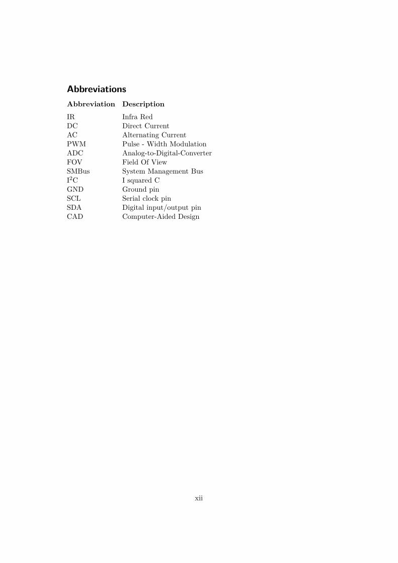
AbbreviationsAbbreviation DescriptionIR Infra RedDC Direct CurrentAC Alternating CurrentPWM Pulse - Width ModulationADC Analog-to-Digital-ConverterFOV Field Of ViewSMBus System Management BusI2C I squared CGND Ground pinSCL Serial clock pinSDA Digital input/output pinCAD Computer-Aided Design
xii
Chapter 1
Introduction
1.1 Background
Until only a few decades ago, infrared (IR) technology was mainly used for militarymeans. It was used for guiding weapons, such as missiles to its target. But today,heat tracking has become more common, since the technology has become lessexpensive (Budzier and Gerlach, 2011).
Applying this technology to robots would open up new ways for usage of robots.It could mean sending in robots instead of humans to put out fires. The TokyoFire Department has already started to use fire fighting robots that can operate insituations that involves large-scale fires and hazardous material (Miyazawa, 2002).The problem is that these are remote-controlled and have no way of detecting heatsources on their own. Although those robots are rather simple and old, the idea ofsending in autonomous robots in life threatening situations is something that othersalso started to develop. Another article shows how the U.S. Navy has started build-ing a humanoid-type robot called the Shipboard Autonomous Firefighting Robot(SAFFiR) that focuses on suppressing fires on ships (Shadbolt, 2015). Even thoughthe robot recently mentioned uses an IR-camera to detect the heat source, an IR-thermometer is easier to apply to a less complex robot.
An IR-thermometer (also known as laser thermometer) is used to find out thetemperature of an object from a distance without any physical contact.
1.2 Purpose
The purpose of this project is to research for the potential in IR technology. Bydoing so, the following research questions needs to be answered:
• How does different distances and angles affect an IR thermometer’s output?
• If IR-technology is implemented on a robot, how effective can an object betraced?
1
CHAPTER 1. INTRODUCTION
1.3 ScopeThe scope of this thesis is to construct a land vehicle that can detect heat sourcesaround it with an IR-thermometer.
Although there are other ways to track heat objects from a distance such as athermal camera, an IR-thermometer was chosen due to it being easy to use, accurateand quite affordable (Melexis, 2009).
There are other types of vehicles that this kind of sensor can be tested with,such as a quadcopter, but a land vehicle was considered the best way to test theIR-thermometer’s capability because it only requires scanning with the sensor inone axis. Moreover, building a quadcopter is time consuming and would lessen thetime put on the main objective of this thesis.
1.4 MethodBefore the robot is fully constructed, a number of tests will be performed on thesensor in order to discover how it works in different angles and distances relativeto a heat source. The answers will provide the knowledge needed to know how therobot will operate in best way. The robot will then be tested for how effective itcan trace a certain object.
2
Chapter 2
Theory
This chapter will present the theory needed to answer the questions in section 1.2and to get a deeper understanding of how the project is designed.
2.1 Pulse Width Modulation (PWM)PWM is a technique used to control the power supplied to electrical devices (Jo-hansson, 2013). By using the knowledge of how PWM works, it was possible tocontrol the angular speed of the direct current (DC) motors, the angle of the servomotor and the ultrasonic sensor (see chapter 3.4). The duty cycle, defined in eq.(2.1.1) and illustrated in figure 2.1 is a very important concept when talking aboutPWM. By setting the time the voltage is on and off, it is possible to control theoutput voltage. For example, if the duty cycle is set to a low value, the angularspeed of DC motors is decreased due to the low output voltage. In Arduino, thePWM is set to the DC motors with the analogWrite() function (Arduino, 2016a).It takes input values in the parenthesis on a scale from 0 to 255. When inserting255 it means that the duty cycle is 100%. In the same way, if a duty cycle of 50%is desired, the input value becomes 127 (or 128, depending on how the rounding isdone).
α = ton
ton + tof f(2.1.1)
3
CHAPTER 2. THEORY
Figure 2.1: PWM signal.
2.2 System Management Bus (SMBus)
When talking about computers, a bus is a communication system that transfer databetween components.
The SMBus is a two-wire bus through which various system component chips cancommunicate with each other and the rest of the system (System Management Inter-face Forum, 2014). A very similar interface, to the SMBus is the I2C communicationinterface, however the SMBus is in a more compact form (NXP Semiconductors,2014). The SMBus is widely used on motherboards for "on/off instructions" andone of the main goals for it is to achieve stability and compatibility.
The main difference between the I2C and the SMBus is that the SMBus limitspeed is between 10kHz and 100kHz meanwhile the I2C is able to support devicesfrom 0Hz to 5MHz. The SMBus includes a clock time-out, which means that it isnot able to do low-speed operations (Melexis, 2008).
2.3 Electromagnetic radiation
Electromagnetic radiation is often described as a classical wave, engaging oscillatingmagnetic and electric fields moving at the speed of light, c, see figure 2.2. However,for some applications, it is useful to see the electromagnetic field as waves existingof small particles of energy, known as photons (Kelley, 2013).
Classically, the electromagnetic field is described by the electric field, E(r, t)and the magnetic field, H(r, t). Both of these quantities are vectors that dependson the time t and the three-dimensional position r. Together with the electricdisplacement, D(r, t) and the magnetic induction B(r, t) the vectors are relatedthrough Maxwell’s equations (Kelley, 2013):
∇ ·D = ρ (2.3.1)
∇×E = −∂B∂t
(2.3.2)
∇ ·B = 0 (2.3.3)
4
2.4. IR-RADIATION
∇×H = J + ∂D∂t
(2.3.4)
where ρ is the density of the electric charge and J is the density of electriccurrent (Kelley, 2013).
Figure 2.2: Principles of electromagnetic wave (Kelley, 2013).
2.4 IR-radiation
IR radiation is an electromagnetic radiation with the wavelength between 700 nm -1 mm. In other words; the IR radiation is found in the wavelength between visibleradiation (visible light) and microwave radiation (Budzier and Gerlach, 2011).
It is a common mistake to state that IR radiation is directly referred to thermalradiation, however almost everybody in everyday use radiates IR radiation of acertain wavelength. The radiation depends on the wavelength which depends onthe body’s temperature. Therefore it is possible to do non-contact temperaturemeasurements of objects using the knowledge of how IR radiation and IR sensorsworks.
IR radiation can also be used to detect motion and the presence of a human bodyand in thermal cameras that makes a diagram (i.e. an image) where it is possibleto see how the temperature variates at different levels on the detected body.
The IR radiation can be classified into four subgroups of IR radiation; nearinfrared (NIR), mid infrared (MIR), far infrared (FIR) and ultrafar infrared (UFIR),the wavelength-range of the subgroups can be found in table 2.1. As mentioned, IRradiation technology makes it possible to do non contact measurements. This makesit possible to do temperature measurements at objects such as fast-moving objects,small objects and objects which are at inaccessible measuring points. (Budzier andGerlach, 2011)
5
CHAPTER 2. THEORY
Table 2.1: The ranges of wavelength for the different subgroups of IR-radiation(Budzier and Gerlach, 2011).
Near Infrared Mid Infrared Far Infrared UltrafarInfrared
2.5 Blackbody radiationHot objects are capable of transferring energy by contact and by emission of radi-ation. Other objects that are only considered to be moderately hot mainly emitinfrared and longer wavelengths, while objects considered to be very hot also emitboth visible and even ultraviolet radiation. An example of an object that emitsinfrared, visible and also ultraviolet light is the sun. An idealized description ofsuch an emitter is a body that is at thermal equilibrium with its environment andcan absorb and emit radiation at all frequencies. A body capable of such a feat iscalled a blackbody and its emission spectrum is referred to as blackbody radiationor blackbody emission. Although there is no such thing as an object with the char-acteristics of a perfect blackbody, the sun and certain broadband light sources thatare used for laboratory spectroscopy works reasonably well approximated as suchan emitter (Kelley, 2013).
All objects with an absolute temperature above zero Kelvin emit radiant energyaccording to the Stefan-Boltzman equation (Halme, 1996):
W = εσT 4 (2.5.1)
Where W is the emitted energy, ε is the emissivity (0 < ε < 1), σ is the Stefan-Boltzmann constant (5.67·10−12 W/cm2K4) and T is the absolute temperature.
Emissivity, ε, is used to measure energy absorption and is defined as the ratio ofradiant energy emitted by a given heat source and the energy emitted by a perfectblackbody under the same conditions (same temperature and area) as the givensource. For a perfect blackbody, the emissivity is 100% (i.e. one), whereas for aperfect reflector (neither absorbing nor emitting radiant energy) the emissivity iszero (Halme, 1996). Different materials have different emissivity, a typical value foraluminium is 0.18 while plastic materials typically have a value around 0.84 - 0.95(Melexis, 2009).
6
2.6. IR-SENSORS
2.6 IR-sensorsThermal sensors works in such way that it absorb radiant flux, φs (W). When theabsorbed radiant flux (power physical quantity) becomes heat, the sensor will getwarmer and due to this heat up a difference in temperature is perceived by thethermometer. It then takes the change in temperature and converts it into anelectrical signal (Vs or Is), see figure 2.3 (Budzier and Gerlach, 2011).
Field of view (FOV) is a central concept when talking about IR sensors. Supposethat the FOV is fixed. If a certain object is moved away from the sensor, it willresult in a less accurate value of the object’s real temperature in the output, sincethe sensor measures the mean value of all the temperatures inside the FOV. Now, inthe same way, but instead the object is at fixed position and the FOV of the sensoris decreased, the output value would be at much larger accuracy. The same theoryapplies when the object is moved sideways in the FOV, with a fixed distance, d. Ifthe object is placed directly in front of the sensor, the output value will be moreaccurate since it have its ”sensitive spot” in the middle (a = 0), see figure 2.4b.
Figure 2.3: Principles of a thermal sensor. (Budzier and Gerlach, 2011).
7
CHAPTER 2. THEORY
(a) (b)
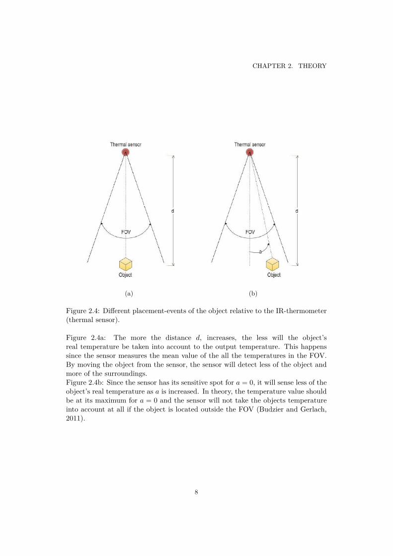
Figure 2.4: Different placement-events of the object relative to the IR-thermometer(thermal sensor).
Figure 2.4a: The more the distance d, increases, the less will the object’sreal temperature be taken into account to the output temperature. This happenssince the sensor measures the mean value of the all the temperatures in the FOV.By moving the object from the sensor, the sensor will detect less of the object andmore of the surroundings.Figure 2.4b: Since the sensor has its sensitive spot for a = 0, it will sense less of theobject’s real temperature as a is increased. In theory, the temperature value shouldbe at its maximum for a = 0 and the sensor will not take the objects temperatureinto account at all if the object is located outside the FOV (Budzier and Gerlach,2011).
8
2.6. IR-SENSORS
To calculate the temperature, IR thermometers use the radiation flux betweenthe sensitive element in the sensor and the object of interest, given by the followingequation (Melexis, 2009):
q = ε1α1T41 σA1Fa−b − ε2T 4
2 σA2 (2.6.1)
Where ε1 and ε2 are the emissivity of the sensitive element and the object respec-tively, α1 is the absorptivity of the sensor, σ i the Stefan-Boltzman constant, A1 andA2 are the surface areas involved in the radiation heat transfer, Fa−b is the shapefactor, T1 and T2 are the temperatures, in Kelvin, of the sensor and the objectrespectively.
In the heat transfer, according to equation (2.6.1) involving an object with lowemissivity (such as aluminum), the portion of radiation to the sensitive elementthat really comes from the object decreases and more IR radiation reflected fromthe environment is absorbed by the sensor. IR thermometers is calibrated to staywithin a specified accuracy, however it cannot separate the radiation from the objectand the radiation reflected from the surrounding (Melexis, 2009).
9
Chapter 3
Demonstrator
3.1 Problem FormulationIn order to answer the research questions in section 1.2, a robot was build. Tosuccessfully build the robot and to make it operate correctly, a number of problemswas formulated:
• How will the sensor cover a larger area than its FOV?
• How does the vehicle move in order to find the warmest object?- The robot does not have a type of homing system, meaning that it will
move blindly without knowing the location of the target.
• How will the sensor find the location of the objects.- The sensor has a 90 FOV but it cannot sense where in the FOV the
target is located.
3.2 SoftwareThe final prototype of the heat following robot scans an area of 180 using a servomotor and takes these angles and refers them to the temperature measured at thatspecific angle (the angle position is the index of the temperature in the array spec-ified in the code, see appendix A). By making it take out the highest temperaturefrom the array, the robot also gets the angular position of that temperature dueto the servo. If the angle is between a certain interval of criteria (specified in thecode), the robot will move towards that angle. The interval is set to make the robotgo straight forward, i.e. the angle should be around 90. The interval is neededbecause otherwise the robot will iterate too many times to be considered as effi-cient. Also, if the interval is too large, the robot will most likely find a temperatureslightly to the side of the object and pass the object instead of moving and stopdirectly in front of it.
11
CHAPTER 3. DEMONSTRATOR
Moreover, the robot doesn’t have a tracking device that can make it adjustitself to face the angle. The solution for this was to make it rotate constantly inone direction in order to measure the time it takes for it to rotate 360 a couple oftimes and take the average of these tests in order to get an approximate value ofthe time it takes to rotate 360. By doing so, the time could be adjusted to make itrotate to certain degrees (divide the time it takes to rotate 360 with 360 to get thetime it takes to rotate 1). Because of this, the robot makes a number of iterationswhen it searches for the object to make an accurate outcome. Once it has found theobject, it will move towards it until the ultrasonic sensor tells it to stop in order tokeep it from colliding into the object.
Figure 3.1 shows the algorithm that is used for the heat following robot. Thealgorithm starts with reading the temperature for pos = 0 (servo angle = 0), theprogram does this for every angle up to 180. At the same time as the program isreading the temperature for every angle, it also compares the temperature to theprevious to get which temperature is the highest and at which angle. Further onif the angle is inside an interval (close to 90) the vehicle will move towards theobject. Note that in figure 3.1 the DC motors will run as long as the distance,dist = 0 (cm). The NewPing library, used to control the Ultrasonic sensor (seesection 3.4.6), makes it possible to define a maximum distance. If the Ultrasonicsensor detects a value above the maximum distance, it will give a 0 to the outputvalue. Therefore, if the UltraSonic sensor detects a nonzero value, the DC-motorswill stop. Also, the Ultrasonic sensor cannot measure distances below 2cm, whichmakes it impossible for the sensor to give an output of 0cm, for distances inside themaximum distance range (ITead Studios, 2010). If the angle is outside this interval,the vehicle will either turn left or right depending on the magnitude of the angle inwhich the warmest object is placed. To get the robot to rotate the desired number ofdegrees, the delay()-function is used. The delay()-function is usually used to pausethe program for the amount of time (in miliseconds) specified in the parenthesis.However, it can also be used to run a certain type of code for a specified amountof time. For example, if the program is specified to run the DC-motors and hasthe delay()-function written in the end, the program will run the DC-motors forthe amount of time specified in the function (Arduino, 2016b). Inside the delay()-function the angle in which the warmest object is placed at is multiplied with thetime it takes for the vehicle to turn 1, here named ”calibrated value”. This valueis called a calibrated value because it needs to be changed as the amount of inputvoltage and the duty cycle is varied.
When the program is finished going right, left or stopping, the algorithm startsover again.
12
3.2. SOFTWARE
Figure 3.1: Simplified flowchart for the heat following robot, made in the onlinesoftware draw.io.
13
CHAPTER 3. DEMONSTRATOR
3.3 ElectronicsIn the schematic figure in figure 3.2 it is shown that pin 9 and 10 are not usedfor the DC motor’s PWM output. The reason is that the code is written withthe analogWrite()-function to set the angular speed of the DC motors, however theservo library disables this function in these pins and therefore it is not possible touse pin 9 and 10 for this kind of purpose (Arduino, 2016c). The servo motor doesnot use the analogWrite()-function, which makes it possible to connect the servoto pin 10 (as seen in figure 3.2). Section 3.4 will more thoroughly explain whatcomponents are used and how they are connected to each other.
Figure 3.2: Schematic figure, made in the free software fritzing, of how the systemis wired.
3.4 HardwareIn this section, it is explained which components are used to this project and howthese are connected to each other. A short explanation of how each and every oneof the components works is available in each subsection. A simplified schematic
14
3.4. HARDWARE
showing how all the components are connected to each other is given in appendixB.
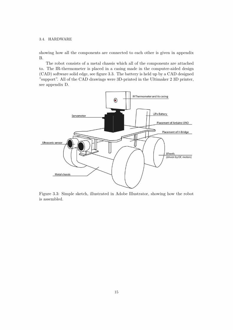
The robot consists of a metal chassis which all of the components are attachedto. The IR-thermometer is placed in a casing made in the computer-aided design(CAD) software solid edge, see figure 3.3. The battery is held up by a CAD designed”support”. All of the CAD drawings were 3D-printed in the Ultimaker 2 3D printer,see appendix D.
Figure 3.3: Simple sketch, illustrated in Adobe Illustrator, showing how the robotis assembled.
15
CHAPTER 3. DEMONSTRATOR
3.4.1 Arduino UNO
The open source hardware Arduino UNO was used in this project. Simply becauseit is easy to use and had the sufficient amount of pins that was necessary for thisproject. To power up the Arduino, a LiPo battery was used and all of the devicescontrolled in this project was connected to the Arduino. Arduino code was used inthis project to create the algorithm for the robot.
3.4.2 DC Motor
The DC motor basically converts electrical energy to mechanical energy. It consistsof a commutator, coil and magnets. When a power source is connected to thecommutator, a current flows through the coil and due to the existing magneticfield a magnetic force arises on the coil. The magnetic force is producing torquewhich makes the DC motor spin. To make a smoother spin, a greater set of coilsand commutator is used. The DC motor used in this project is the DAGU DG02S-A130GEARMOTOR (DAGU Hi-Tech Electronic Co., 2013). As described in section3.4.4 the DC motors is connected in parallel to the H-Bridge module’s ports. Thesame LiPo battery, that is used to power up the Arduino, is used to give power tothe DC motors.
3.4.3 Servomotor
A servomotor is commonly known as a robots muscle and is often used for motioncontrol. It works as a rotary device that allows for precise control of angular position(Darren Sawicz, 2008). Servos are controlled by sending a PWM signal through thecontrol wire that determines the position, depending on the width of the pulse (i.e.it is not the duty cycle itself that control the position). For this project, the FutabaS3003 servo (Hobbico, 2011) is used to rotate the IR-sensor 180.
3.4.4 Dual H-Bridge Module
In this project a dual H-bridge motordriver module was used to control the four DCmotors. The module uses the ST L298N dual full-bridge driver (STMicroelectronics,2000). The module is constructed to control two DC motors and since four DCmotors was used in this project, it was necessary to connect two DC motors inparallel at each side of the module, see appendix B. This led to a simultaneouscontrol of the pair of DC motors at each side. In the module there are six pins;four digital pins (to control the direction of the DC motors) and two PWM pins (tocontrol the angular speed). These pins where connected to the Arduino’s digitaland PWM pins respectively.
16
3.4. HARDWARE
3.4.5 IR-thermometer (MLX90614)The MLX90614 is an IR thermometer used for non contact temperature measure-ments. The sensor model used in this project is the MLX90614-AAA that has a 90
FOV and needs to be connected to the Arduino’s 5V pin. It is able to measure thetemperature of a certain object, as well as the ambient temperature (which is thetemperature of the sensor itself). The range of measurements it can do in sensortemperature mode is between -40 to 125C and in the object temperature mode itis able to measure between -70 to 380C. The thermometer has a 17-bit analog todigital converter (ADC) built into it which means it can create an output resolutionof around 0.0034C when measuring the temperature of an object. However, in thisproject the thermometer is connected using the SMBus, which means the outputresolution of 0.02C is achieved (Melexis, 2009). By measuring the temperature ofan object the sensor actually measures the average value of all the objects in theFOV of the sensor (Melexis, 2009).
To make the sensor more immune against ambient- and sunlight, an optical filter(a long-wave pass filter) that cuts off visible and near IR radiant flux is integratedin the sensor.
The sensor uses the SMBus interface to communicate with the microcontrollerand has four pins: Ground (Vss), Serial clock (SCL), Digital input/output (SDA),External supply voltage (Vdd). Vss is wired to the Arduino’s GND (ground) pin,the Vdd to the 5V pin, the SCL to the A5 pin and the SDA is connected to the A4pin. It has a fixed I2C address which means that it is only possible to connect andcontrol one sensor per microcontroller. In this project the wire library is used andsince the wire library uses 7-bit addresses the fixed 7-bit I2C address 0x5A for thesensor was used.
The circuit is connected according to figure 3.4, the resistors in the figure arepull-up resistors that are chosen to be at standard value of 4.7kΩ and the capacitorhas a value of 0.1µF.
17
CHAPTER 3. DEMONSTRATOR
Figure 3.4: MLX90614 SMBus connection (Melexis, 2009). Note that theMLX90614-AAA was used in this project which means that the Vdd pin was con-nected to Arduino’s 5V pin, not the 3.3V pin as shown in the picture. The coupleprinciples are exactly the same besides the Vdd pin are connected to another voltagesupply.
Placement of IR-thermometer
The placement of the IR-thermometer was crucial for the robot to properly work asdesired. At first it was placed in front of the robot, with a distance from the robot’scenter, in order to get as clear FOV as possible. But what was realized after wasthat the servo the IR-thermometer is placed on gives an angle that is not adjustedto the center of the robot’s center, which would result with the robot not rotatingcorrectly for objects at longer distances, see figure 3.5a and 3.5b. Eventually, theIR-thermometer and the servo was instead placed on the center of the robot in orderto avoid errors at longer distances.
Figure 3.5a shows the placement of the sensor in the first prototype meanwhilefigure 3.5b shows the placement of the sensor in the final prototype. The vehicleangle can be calculated according to (3.4.1) if the object is placed to the left of thevehicle and as (3.4.2) if the object is placed to the right of the vehicle.
θvehicle = 90 − θservo (3.4.1)
θvehicle = θservo − 90 (3.4.2)
18
3.4. HARDWARE
(a) (b)
Figure 3.5: As shown in the figures above, writing the vehicle angle, θvehicle, as afunction of the servo angle, θservo, became a lot easier when the servo was movedto the same center as the vehicle.
19
CHAPTER 3. DEMONSTRATOR
3.4.6 Ultrasonic SensorAn ultrasonic sensor was used for distance measurements. The sensor sends a high-frequency (above audible) sound pulse. This sound pulse is reflected by a possibleinterfering object. The reflected sound is then received again by the sensor. It thencalculates the distance with the time for the pulse to come back combined with thevelocity of sound in air.
The model used for this project is the Ultrasonic Ranging Module HC - SR04.Its purpose was to keep the robot from colliding into the object it moves towards.The Arduino library used to control the sensor is the Parallax Ping library (CalebZulawskis, 2012).
20
Chapter 4
Results
Applying an IR-sensor that measures heat to a robot worked successfully. The robotcan find the object that emits most heat in a wide area. Seeing as how the servorotates 180 and the sensor has a 90 FOV, means that it covers additional 45 oneach side. That means that the robot has a total FOV of 270, meaning that itcovers a wide area around it.
All tests in this section were made with an electric plastic (since plastic has highemissivity) kettle filled with 1.7l of boiled water (90C when measuring the waterwith a cooking thermometer). Note that the IR-thermometer does not measure theactual temperature of the water, but the surface temperature of the container.
4.1 Testing of the IR-thermometerTwo types of tests was done to test the theory in section 2.6:
• How does the output temperature variate when moving the object from thesensor (object straightly in front of sensor)?
- A new value of the temperature was noted every 4cm.
• How does the output temperature variate when changing the angle from themiddle point (fixed distance from sensor = 60cm)?
The charts in fig. 4.1 and fig. 4.2 shows how the theory described in section 2.6actually applies in reality. It clearly shows as the object is moved away from thesensor, the temperature decreases. It also shows how the temperature is at itshighest value when the object is directly in front of the sensor.
21
CHAPTER 4. RESULTS
Figure 4.1: Temperature/Distance plot, plotted in the software Matlab. For exactvalues, see appendix C.
Figure 4.2: Temperature/Angle plot, plotted in the software Matlab. Particularly,this graph shows that the sensor does not react until around −50. This is correctsince the FOV spreads in two directions. This test was only made from the rightside of the sensor (90
2 = 45). For exact values, see appendix C.
22
4.2. TESTING OF THE ROBOT
4.2 Testing of the RobotThe IR-thermometer was first placed close (around 1 cm) to the surface of the kettleto measure the surface temperature, which gave an output of 83C. The test of therobot was then done by placing the kettle a distance from the robot. The distancewas set to be 60 cm because it was enough distance to do the measurements whilethe IR-thermometer still could ”notice” the difference in temperature between thekettle and the ambient temperature, (see figure 4.1). Five tests to the three scenariosbelow was made and the number of iterations the robot had to do together with thetime it took for the robot to find the warmest object was written down, see table4.1, 4.2 and 4.3.
Table 4.1: Tests made while the kettle was directly in front (θvehicle =0) of therobot (see the referred angle in figure 3.5b in section 3.4.5).
Test No. No. of Iterations Time [s]1 1 6.42 1 6.23 1 5.84 1 6.05 1 6.0
Table 4.2: Tests made while the kettle was to the left (θvehicle =- 90) of the robot(see the referred angle in figure 3.5b in section 3.4.5).
Test No. No. of Iterations Time [s]1 8 69.72 5 47.83 6 48.14 6 52.55 6 44.4
Table 4.3: Tests made while the kettle was to the right (θvehicle =90) of the robot(see the referred angle in figure 3.5b in section 3.4.5).
Test No. No. of Iterations Time [s]1 10 75.92 4 37.73 6 55.74 6 44.95 3 21.5
23
Chapter 5
Discussion and conclusions
5.1 Discussion
The first thing to be discussed is how the different distances and angles affect thesensors output. The temperature variates when the object is moved around in theFOV of the sensor and decreases when the object is moved away from the IR-thermometer’s middle point (the peak zone), see section 4.1. This property of theIR-thermometer was used for tracking objects since the IR-thermometer is morecapable of ”distinguishing” the object due to the IR-thermometer’s peak zone. Thismeans that the IR-thermometer will give a stronger output somewhere in its FOVwhich means that the warmest object should be located somewhere around theposition of the peak zone.
The second thing to be discussed is the efficiency of the sensor while implementedon a robot. Although it managed to detect objects and locate them, the amountof iterations it took to locate varied most of the time in the two experiments thatinvolved the robot locating an object from the side. Even though the method usedfor making the robot turn to its target is ineffective, the same conditions was setfor each test and yet it varied several times.
The robot is effective in the meaning that it can track objects, using only theobject’s heat. However, a plastic kettle was used in the tests, and according tosection 2.5 plastic has high emissivity which means that the sensor is able to perceivemore IR-radiation from the object and less from the surroundings. Not every objecthas an emissivity as high as the plastic kettle that was used in section 4.1 and 4.2.Some have lower emissivity which makes it harder for the sensor to sense an objectat longer distances.
Also to this question it should be mentioned that the robot moves blindly, i.e.it does not have a component that is able to sense in which direction the robotis pointing at. This means that the robot’s inefficiency could depend on that theangle in which it moves is approximated. If a ”homing system” would be applied, therobot could have in the best conditions find the heat source within two iterations:the first iteration to scan the object and rotate so that it point directly on the object
25
CHAPTER 5. DISCUSSION AND CONCLUSIONS
and the second iteration to scan again and move straight towards the object.
5.2 ConclusionsThe purpose of this thesis was displayed as a set of research questions. Due to testsaround these research questions a conclusion has been reached for each question.
• How does different distances and angles affect the sensors output?Section 4.1 shows that the temperature decreases when the object is movedaway from the sensor. The temperature also decreases as the object is movedaway from the center line.
• If IR-technology is implemented on a robot, how effective can an object betraced?In conclusion the robot could find the heat source using the attached IR-thermometer, however it could not find the object as fast as desired. Meaningthat the technology is not as efficient as it could be.
26
Chapter 6
Recommendations and future work
Though the robot managed to detect heat sources, there were a few things that couldbe changed or in other cases improved. The solution for the robots "blindness" whichmade it unable to get a specific location of the heat source was solved due to testingsand approximations. Instead, it could have been solved with the use of a triple axismagnetometer (also known as a digital compass). The triple axis magnetometer iscapable of sensing directions due to magnetic fields. The model recommended is theHMC5883L (Honeywell, 2013) which is compatible with the Arduino board. Theproblem is that it requires I2C which is already used for the IR-thermometer, butit should not be a problem if you connect two Arduino boards together.
Another thing that should be considered is to use a different type of IR-thermometer.The IR-thermometer used for this thesis is an MLX90614-AAA which covers a 90
FOV and as mentioned in section 5.1, the IR-thermometer takes the average of ev-erything it senses, meaning everything in its FOV. That is why it is recommendedto instead use the MLX90614ESF-ACF (Melexis, 2009). The MLX90614ESF-ACFhas a FOV of merely 10 which means that it gives more accurate values since itdoesn’t take as much of the surroundings into consideration.
To further test the theory in this report, it would be appropriate to make varioustests including more objects of different sizes and materials.
One more thing that can be further worked on is to make the robot activelyfollow the target in case the object is moving. By introducing a controller suchas PID, the robot would be able to regulate the speed to keep the robot at aconstant distance from the object at all time. Also, implementing several sensorsthat together can determine whether or not an object is in front of the robot wouldbe a recommendation to decrease the amount of errors.
27
Bibliography
Arduino (2016a). AnalogWrite(). Available from: https://www.arduino.cc/en/Reference/AnalogWrite [cited 2016-05-09].
Arduino (2016b). Delay(). Available from: https://www.arduino.cc/en/Reference/Delay [cited 2016-05-17].
Arduino (2016c). Servo Library. Available from: https://www.arduino.cc/en/Reference/Servo [cited 2016-05-17].
Budzier, H. and Gerlach, G. (2011). Thermal Infrared Sensors - Theory, Optimisa-tion and Practise. John Wiley & Sons, 1st edition.
Caleb Zulawskis (2012). Ping Library for Arduino. Available from: http://playground.arduino.cc/Code/Ping [cited 2016-05-09].
Kelley, A. M. (2013). Condensed-Phase Molecular Spectroscopy and Photophysics.John Wiley & Sons, 1st edition.
Melexis (2008). SMBus communication with MLX90614. Available from: http://www.generationrobots.com/media/SMBus-communication-with-MLX90614.pdf [cited 2016-05-09].
Melexis (2009). Melexis MLX90614 Datasheet. Available from: http://docs-europe.electrocomponents.com/webdocs/0db7/0900766b80db745c.pdf [cited 2016-05-09].
Miyazawa, K. (2002). Fire robots developed by the Tokyo Fire Department. TayloFrancis Online. Available from: http://www.tandfonline.com/doi/pdf/10.1163/156855302320535953.
NXP Semiconductors (2014). I2C-bus specification and user manual. Availablefrom: http://www.nxp.com/documents/user_manual/UM10204.pdf [cited 2016-05-09].
Shadbolt, P. (2015). U.S. Navy unveils robotic firefighter. CNN. Available from:http://edition.cnn.com/2015/02/12/tech/mci-saffir-robot/.
System Management Interface Forum (2014). System Management Bus (SMBus)Specification. Available from: http://smbus.org/specs/SMBus_3_0_20141220.pdf [cited 2016-05-09].
The following two pages includes the code used for this project.
31
//Wire library to communicate with the I2C interface#include <Wire.h>
//NewPing library to use the ultrasonic sensor #include <NewPing.h>//Servo library to use the servo motor#include <Servo.h>//Defining the standard address for the IR-Thermometer#define I2C_ADDR 0x5A
Servo myservo;
//Define pins for the DC-motorsint pinI1 = 7; //define I1 portint pinI2 = 8; //define I2 portint speedpin = 3; //define EA port (PWM speed regulation)int pinI3 = 12; //define I3 portint pinI4 = 13; //define I4 portint speedpin2 = 11; //define EB port (PWM speed regulation)
int Triggerpin = 5;int Echopin = 6;int Maxdist = 20;
float Array[180]; //initiate the array to save the temperatures
NewPing sonar(Triggerpin, Echopin, Maxdist);
void setup()
myservo.attach(10); // Attaches the servo on pin 10 to the servo object
Serial.begin(9600); //Serial begin to print out the temperatures
//Initiating the I2C busWire.begin();
//Define the pins as output (DC motor pins)pinMode(pinI1, OUTPUT);pinMode(pinI2, OUTPUT);pinMode(speedpin, OUTPUT);pinMode(pinI3, OUTPUT);pinMode(pinI4, OUTPUT);pinMode(speedpin2, OUTPUT);
void loop()
//Setting HIGH on all pins to make the DC motors to stop.digitalWrite(pinI1, HIGH);digitalWrite(pinI2, HIGH);digitalWrite(pinI3, HIGH);digitalWrite(pinI4, HIGH);
delay(1000);
//Initiating values to begin the different loops belowint state = 0;int Randomvar = 0;int pos = 0;float max_temp = 0;float max_pos = 0;
if (Randomvar == 0) //Is running as long as Randomvar variable is zero. At the end of this statement the Rfor (pos = 0; pos <= 180; pos += 1) //goes from 0 degrees to 180 degrees with one step in between.
myservo.write(pos); //tell servo to go to position in variable 'pos'
/*Beräkning av temperatur*/const float tempFactor = 0.02; //0.02°C per LSB -> The resolution of the IR thermometerfloat tempData = (tempFactor * data) - 0.01;float celsius = tempData - 273.15; //Converts from Kelvin to Celsius
Array[pos] = celsius; //Assigning the temperature to the array.
//Printing out the current position and the temperature at that positionSerial.print(pos);Serial.print(" ");Serial.println(Array[pos]);
//Calculating the maximum temperatureif(Array[pos] > max_temp)
max_temp = Array[pos];max_pos = pos;
delay(30);Randomvar = 1;
//If - statement to assign the specific state in which the robot is in. It can move to right, left or forward.if (max_pos >= 80 && max_pos <= 100)
state = 0;else if (max_pos > 95)
state = 1;else if (max_pos < 85)
state = 2;
//Switch-statement to tell the robot what it should do.switch(state)
case 0: //Making the robot move forward. The robot will stop until when the ultrasonic sensor is sensing a nonzero output.
int uS = sonar.ping();int dist = 0;while (dist == 0)
case 1: //Making the robot turn right. The time it takes for the robot to rotate 1° = 2.685 ms (Input voltage = 11.85 V and dutycint fordon_pos = max_pos - 90;digitalWrite(pinI1, LOW);digitalWrite(pinI2, HIGH);digitalWrite(pinI3, LOW);digitalWrite(pinI4, HIGH);analogWrite(speedpin, 100);analogWrite(speedpin2, 100);
delay(fordon_pos*2.685);break;
case 2: //Making the robot turn left. The time it takes for the robot to rotate 1° = 2.685 ms (Input voltage = 11.85 V and dutycy


![APPLICATION OF AN INDUSTRIAL ROBOT IN MASTER- SLAVE ... · control types: sequence-controlled robot, trajectory operated robot, adaptive robot, and teleoperated robot [3]. All the](https://static.documents.pub/doc/80x56/5e6b1cea91c4094ea54e3c74/application-of-an-industrial-robot-in-master-slave-control-types-sequence-controlled.jpg)
