HEAT PUMP WITH ROCK, GROUND OR LAKE AS HEAT SOURCE. NIBE™ F1255 GROUND SOURCE HEAT PUMP • Optimal annual heating factor thanks to the inverter controlled compressor. • Available in two sizes – 1,5 - 6 kW – 4 -16 kW • Minimal operating costs, the compressor increases/ decreases speed according to the prevailing heating demand. • Software controlled circulation pumps that supply the heat pump and the heating system with suitable flow. • It also gives you the opportunity to control comfort in your home no matter where you are by using NIBE Uplink TM . • Display unit with large and easy-to-read colour screen (TFT). – User friendly control system. – Icons and text for clear information about status, temperatures and settings in the heat pump. – indoor sensor included. • High temperature range – Flow line temperature up to 65°C (70°C) – Return line temperature up to 58°C • Integrated clock with real time function for scheduling changing of hot water and indoor house temperature. • Prepared for (with accessory): – Pool heating (POOL40) for both pool and spa. – Control of up to four heating systems (ECS40/ECS41). – Status and settings via NIBE Uplink TM or via SMS (SMS40). – Active / passive cooling with PCM 40/42 or HPAC 40. • Easy to remove the cooling module.
Transcript
Heat pump witH rock, ground or lake as Heat source.
RockThe heat pump collects a proportion of the rock’s stored solar energy via a collector in a bore hole in the rock.
Surface soil The heat pump obtains a proportion of the ground's stored solar energy via the buried ground collector.
Lake The heat pump obtains a proportion of the water’s stored solar energy via the lake collector that is anchored on the lake bed.
Sleeve pipe
Brine to heat pump
Ground water level
Active borehole (water column in
rock)
Brine from heat pump
NIBE F1255 3
How does F1255 work?
VVKVKBinVBf VBrKBut
Principle of operationF1255 consists of heat pump, water heater, electric heater, low energy circulation pumps and control system. F1255 is connected to the brine and heating medium circuits. The heat from the heat source (rock, soil, lake) is taken up via a closed brine system in which a mixture of water and antifreeze circulates. In some cases, the ground water can also be used as heat source. An intermediate heat exchanger should be used to protect the heat pump in such cases.
In the heat pump evaporator, the brine (water mixed with anti-freeze, e.g. glycol or ethanol) releases its energy to the refrigerant, which is vaporised in order to be compressed in the compressor. The refrigerant, the temperature of which has now been raised, is passed to the condenser where it gives off its energy to the heating medium circuit and, if necessary, to any docked water heater. If there is a greater need for heating/hot water than the compressor can provide there is an integrated immersion heater.
Evaporator
Circulation pump
Heating medium
supply Brine in
Hot water Cold water
Water heater
Charge coil
Brine out
Heating medium return
Expansion valve
Shut off valves
Immersion
heater
Reversing
valve
Compressor
Brine pump
Condenser
Cooling module
NIBE F1255NIBE™ F1255 is a heat pump for heating small houses and smaller multi-occupancy houses. The heat pump automatically adjusts itself to the output requirement of the house during the year. When more heat and hot water is required, the output increases, when not so much is needed, it drops to a lower speed. This results in optimal savings as the heat pump always runs at the correct performance all year round. Both the low energy circulation pumps and the flexible hoses are integrated, and the brine circuit can be connected on either side. Particle filter supplied. The heat pump can be connected to a low temperature distribution system. e.g. radiators, convectors or under floor heating. F1255 is equipped with a 180 litre water heater, which is optimallt insulated for minimal heat loss. F 1255-6 kW has an integrated 6,5 kW immersion heater and F1255-16 kW an integrated 7 step 7 kW immersion heater (can be reconnected to a 4-step 9 kW immersion heater). F1255 is constructed on a robust frame with durable panels and effective soundproofing for the best possible comfort. All panels are easy to remove for easy access when installing and for any servicing.
4 NIBE F1255
R
0
+ 20-2
1
R
0
H M flo w4 9 (5 0 ) °CH o t w a te r 5 1 °C
+20
-2
1 R0
HM
flow4
9 (5
0) °C
Hot
wate
r51 °C
R0
Transport and storageF1255 should be transported and stored vertically in a dry place.
When being moved into a building, F1255 may be leant back 45°. Note! Can be tail heavy.
If the cooling module is pulled out and transported upright, F1255 can be transported on its back.
Assembly• Position the heat pump on a firm base, preferably on a concrete
floor or foundation. Use the heat pump’s adjustable feet to obtain a stable set-up.
• Install with its back to an outside wall, ideally in a room where noise does not matter, in order to eliminate noise problems. If this is not possible, avoid placing it against a wall behind a bedroom or other room where noise may be a problem.
• Wherever the unit is located, walls to sound sensitive rooms should be fitted with sound insulation.
• Route pipes so they are not fixed to an internal wall that backs on to a bedroom or living room.
Installation areaLeave a space of 800 mm in front of the heat pump. Approximately 50 mm free space is required in order to open the side hatches. The hatches do not need to be opened during service, all service on F1255 can be carried out from the front. Leave space between the heat pump and wall behind (and any routing of supply cables and pipes) to reduce the risk reproduction of any vibration. Drawing out the cooling module
To simplify transport and service, the heat pump can be separated by pulling the cooling module out from the cabinet.
See the installer manual for more comprehensive instructions about the separation.
good to know about nibe™ F1255
(50) (50)
800
LEK
Supplied components
LEK
LEK
LEK
Outdoor sensor Current sensor Indoor sensor
LEK
LEK
Level vessel Safety valve 0.3 MPa (3 bar)
O-rings
LocationThe enclosed kit is located on the packaging for the heat pump.
Conex connectors
22 28
Particle filterF1255-6 1 pcs R25 1 pcs R20
F1255-16 1 pcs R32 1 pcs R25
NIBE F1255 5
good to know about nibe™ F1255
Dimensions
620
600
560 440
70
1775
650*
25-
50
25
50
130210
390470525
650*
*This dimension applies at 90° angle on the brine pipes (side connection). The dimension can vary approx. ±100 mm in height as the brine pipes partially consist of flexible pipes.
6 NIBE F1255
good to know about nibe™ F1255
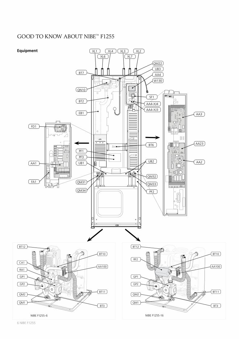
Equipment
FD1
FA1
AA3
AA1 AA2
AA23
F1255
XL1 XL3XL4 XL2
XL6 XL7
QN10
BT7
SF1
AA4-XJ4
AA4-XJ3
W130
AA4
UB3
EB1
BT2
UB1
QM22
QM34
QM31
UB2
BT6
PF2
QM32
QM33
PF1
PF3
LEK
LEK
BT10
BT3
QM2
GP2
BT12
GP1
QM1
CA1
RA1AA100
BT11
NIBE F1255-6
LEK
BT10
BT3
QM2
GP2
BT12
GP1
QM1
RF2
AA100
BT11
NIBE F1255-16
NIBE F1255 7
good to know about nibe™ F1255
Pipe connections
XL1 Connection, heating medium supply
XL2 Connection, heating medium return
XL3 Connection, cold water
XL4 Connection, hot water
XL6 Connection, brine in
XL7 Connection, brine out
HVAC components
GP1 Circulation pump
GP2 Brine pump
QM1 Drainage, climate system
QM2 Draining, brine side
QM22 Venting valve, coil
QM31 Shut-off valve, heating medium supply
QM32 Shut off valve, heating medium return
QM33 Shut off valve, brine out
QM34 Shut-off valve, brine in
QN10 Reversing valve, climate system/water heater
Sensors etc.
BT2 Temperature sensor, heating medium supply
BT3 Temperature sensor, heating medium return
BT6 Temperature sensor, hot water charging
BT7 Temperature sensor hot water top
BT10 Temperature sensor, brine in
BT11 Temperature sensor, brine out
BT12 Temperature sensor, condenser supply line
Electrical components
AA1 Immersion heater card
AA2 Base card
AA3 Input circuit board
AA4 Display unit
AA4-XJ3 USB port
AA4-XJ4 Service socket (no function)
AA23 Communication board
AA100 Joint card
EB1 Immersion heater
FA1 Miniature circuit-breaker
FD1 Temperature limiter/Emergency mode thermostat
CA1 Capacitor
RA1 Choke
RF2 EMC-filter
SF1 Switch
W130 Network cable for NIBE Uplink™
Miscellaneous
PF1 Rating plate
PF2 Type plate, cooling section
PF3 Serial number plate
UB1 Cable gland, incoming electricity
UB2 Cable grommet
UB3 Cable gland, rear side, sensor
Designations in component locations according to standard IEC 81346-1 and
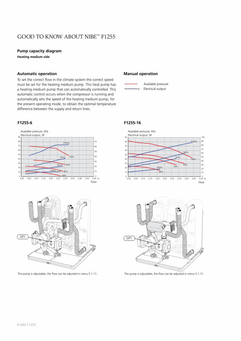
Automatic operationTo set the correct flow in the climate system the correct speed must be set for the heating medium pump. This heat pump has a heating medium pump that can automatically controlled. This automatic control occurs when the compressor is running and automatically sets the speed of the heating medium pump, for the present operating mode, to obtain the optimal temperature difference between the supply and return lines.
Pumpkapacitet, köldbärarsida för F1155-1255 -6 kW, manuell drift.
0
10
20
30
40
50
60
70
80
20
40
60
80
100
120
140
P100%
100%
80%
60%
40%
P80%
P60%
P40%
0
10
20
30
40
50
60
70
80
90
100
0,00 0,10 0,20 0,30 0,40 0,600,50 l/s
Flöde
Tillgängligt tryck, kPa
P Eleffekt, W
kPaTillgängligt tryck
WEleffekt
Pumpkapacitet, köldbärarsida för F1155-1255 -16 kW, manuell drift.
0
P100%
100%
80%
60%
40%
P80%
P60%
P40%
0
20
40
60
80
100
120
140
160
180
200
0,00 0,10 0,20 0,400,30 0,50 0,800,700,60 l/s
F1255-6
LEK
GP2
The pump is adjustable, the flow can be adjusted in menu 5.1.9.
LEK
LEK
GP2
The pump is adjustable, the flow can be adjusted in menu 5.1.9.
Flöde
Tillgängligt tryck, kPa
P Eleffekt, W
kPaTillgängligt tryck
WEleffekt
Pumpkapacitet, köldbärarsida för F1155-1255 -6 kW, manuell drift.
0
10
20
30
40
50
60
70
80
20
40
60
80
100
120
140
P100%
100%
80%
60%
40%
P80%
P60%
P40%
0
10
20
30
40
50
60
70
80
90
100
0,00 0,10 0,20 0,30 0,40 0,600,50 l/s
Flöde
Tillgängligt tryck, kPa
P Eleffekt, W
kPaTillgängligt tryck
WEleffekt
Pumpkapacitet, köldbärarsida för F1155-1255 -16 kW, manuell drift.
0
P100%
100%
80%
60%
40%
P80%
P60%
P40%
0
20
40
60
80
100
120
140
160
180
200
0,00 0,10 0,20 0,400,30 0,50 0,800,700,60 l/s
F1255-16
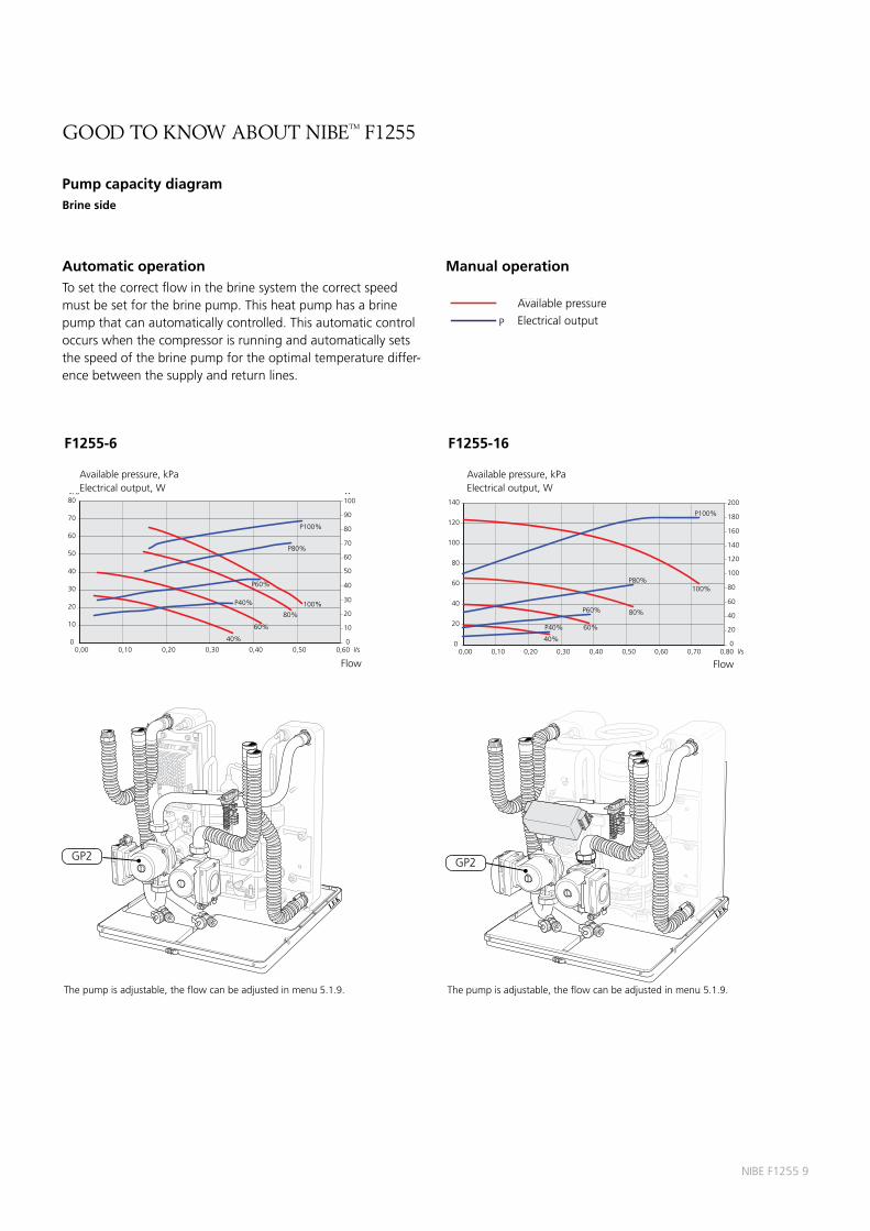
Automatic operationTo set the correct flow in the brine system the correct speed must be set for the brine pump. This heat pump has a brine pump that can automatically controlled. This automatic control occurs when the compressor is running and automatically sets the speed of the brine pump for the optimal temperature differ-ence between the supply and return lines.
Manual operation
FlowFlow
Available pressure, kPaElectrical output, W
Available pressure, kPaElectrical output, W
10 NIBE F1255
F1255
tHe display
Display unit
Display, A
Instructions, settings and operational information are shown on the display. The easy-to-read display and menu system, facilitates navigation between the different menus and options to set the comfort or obtain the information you require.
Status lamp, B
The status lamp indicates the status of the heat pump. It:
A large, easy to rad multicoulour display gives everyone the chance to maximize the energy saving potential of this exciting green technology!
INDOOR CLIMATE HOT WATER
HEAT PUMP
NIBE F1255 11
tHe display
Menu system When the door to the heat pump is opened, the menu system’s four main menus are shown in the display as well as certain basic information.
Menu 1 – Indoor climate
Setting and scheduling the indoor climate.
Menu 2 – Hot water
Setting and scheduling hot water production.
This menu only appears if a water heater is docked to the heat pump.
Menu 3 - Info
Display of temperature and other operating information and access to the alarm log.
Menu 4 – Heat pump
Setting time, date, language, display, operating mode etc.
Menu 5 - Service
Advanced settings. These settings are not available to the user. The menu is visible by pressing the Back button for 7 seconds.
Start guideThe first time the heat pump is started a start guide is started. The start guide instructions state what needs to carried out at the first start together with a run through of the heat pump’s basic settings.
The start guide ensures that the start-up is carried out correctly and cannot be bypassed. The start guide can be started later in menu 5.7.
Indoor temperature - (if a room sensor is connected)
Outdoor temp.Hot water temp.
Extra hot water (if activated)
Estimated amount of hot water
If the start guide is left on this page it closes automatically in 58 min
NIBE UplinkTM This symbol indicates whether F1255 has contact with NIBE Uplink™.
12 NIBE F1255
installation
PipeinstallationPipe installation must be carried out in accordance with current norms and directives. F1255 can operate with a return temperature of up to 58 °C and an outgoing temperature from the heat pump of 70 °C (65 °C with only the compressor).
F1255 is not equipped with shut off valves; these must be installed outside the heat pump to facilitate any future servicing.
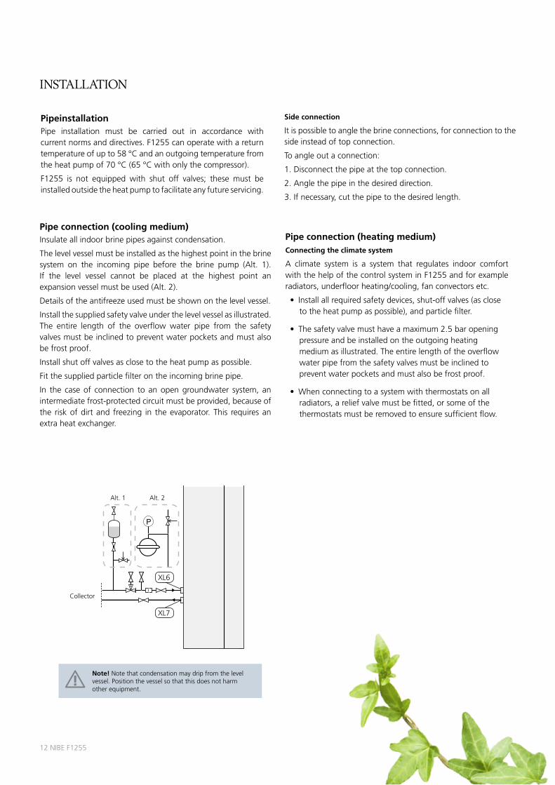
Pipe connection (cooling medium)Insulate all indoor brine pipes against condensation.
The level vessel must be installed as the highest point in the brine system on the incoming pipe before the brine pump (Alt. 1). If the level vessel cannot be placed at the highest point an expansion vessel must be used (Alt. 2).
Details of the antifreeze used must be shown on the level vessel.
Install the supplied safety valve under the level vessel as illustrated. The entire length of the overflow water pipe from the safety valves must be inclined to prevent water pockets and must also be frost proof.
Install shut off valves as close to the heat pump as possible.
Fit the supplied particle filter on the incoming brine pipe.
In the case of connection to an open groundwater system, an intermediate frost-protected circuit must be provided, because of the risk of dirt and freezing in the evaporator. This requires an extra heat exchanger.
Side connection
It is possible to angle the brine connections, for connection to the side instead of top connection.
To angle out a connection:
1. Disconnect the pipe at the top connection.
2. Angle the pipe in the desired direction.
3. If necessary, cut the pipe to the desired length.
Pipe connection (heating medium)Connecting the climate system
A climate system is a system that regulates indoor comfort with the help of the control system in F1255 and for example radiators, underfloor heating/cooling, fan convectors etc.
Note! Note that condensation may drip from the level vessel. Position the vessel so that this does not harm other equipment.
P
P
Alt. 1 Alt. 2
Collector
XL7
XL6
NIBE F1255 13
installation
Ventilation recoveryThe installation can be supplemented with the exhaust air module NIBE FLM to provide ventilation recovery.
Pipes and other cold surfaces must be insulated with diffusion-proof material to prevent condensation.
The brine system must be supplied with a pressure expansion vessel. If there is already a level vessel installed this should be replaced.
PoolThe installation can be supplemented with accessory POOL 40, to provide pool and spa heating. If pool is installed, the collector must be dimensioned after this.
Two or more climate systemsThe unit can be supplemented with accessory ECS 40/ECS 41 for control of two or more climate systems at different temperatures, e.g. under floor heating and radiator system.
Free cooling The installation can be supplemented with fan convectors, for example, in order to allow connections for free cooling (PCS 44).
Inspection of the installationCurrent regulations require the heating installation to be inspected before it is commissioned. The inspection must be carried out by a suitably qualified person and should be documented. The above applies to closed heating systems. If the heat pump is replaced, the installation must be inspected again.
Guideline values for collectorsThe length of the collector hose varies depending on the rock/soil conditions, climate zone and on the climate system (radiators or underfloor heating).
Max length per collector should not exceed 400 m.
In those cases where it is necessary to have several collectors, these should be connected in parallel with the possibility of adjusting the flow of the relevant coil.
For surface soil heat, the hose should be buried at a depth of about 1 metre and the distance between the hoses should be at least 1 metres.
For several bore holes, the distance between the holes must be at least 15 metres.
Ensure the collector hose rises constantly towards the heat pump to avoid air pockets. If this is not possible, air vents should be used.
As the temperature of the brine system can fall below 0 °C it must be protected against freezing down to -15 °C. One litre of ready mixed brine per meter of collector hose (applies when using PEM-hose 40 x 2.4 PN 6.3) is used as a guide value when making the volume calculation.
Control, generalThe indoor temperature depends on several factors. Sunlight and heat emissions from people and household machines are normally sufficient to keep the house warm during the warmer parts of the year. When it gets colder outside, the climate system must be started. The colder it is outside, the warmer radiators and floor heating system must be.
The heat pump is controlled by built-in sensors for flow and return brine temperatures (collector). Brine return temperatures can, if so required, be limited to a minimum (e.g. for ground water systems).
Control of the heat production is performed based on the “floating condensing” principle, i.e. the temperature level needed for heating at a specific outdoor temperature is produced guided by collected values from the outdoor and flow sensors. The room temperature sensor can also be used to compensate the deviation in room temperature.
16 NIBE F1255
installation
Additional heat onlyF1255 can be used exclusively as an additional heater (max. 6,5kW for F1255-6 and max 9 kW for F1255-16), to produce heat and hot water, for example before the collector installation is complete.
Brine pumpThe brine pump normally follows the operation of the heat pump. There is a special operating mode for continuous operation for 10 days, followed by return to normal mode (this may be used before stable circulation has been established).
Alarm indicationsThe status lamp lights red in the event of an alarm and the display shows detailed information depending on the fault. An alarm log is created with each alarm containing a number of temperatures, times and the status of outputs.
Own curveF1255 has pre-programmed non linear heating curves. It is also possible to create an own defined curve. This is an individual linear curve with one break point. You select a break point and the associated temperatures.
Under floor dryingF1255 has an integrated floor drying function. This allows for controlled drying of a concrete slab. It is possible to create your own program and to follow a pre-programmed time and temperature schedule.
Heat productionThe supply of heat to the house is regulated in accordance with the chosen setting of the regulating curve (curve slope and offset). After adjustment, the correct amount of heat for the outside temperature is supplied. The flow line temperature of the heat pump will hunt around the theoretically required value. For subnormal temperatures the control system calculates a heating deficit in the form of “degree-minutes”, which means that heating production is accelerated. The larger the subnormal temperature, the greater the heat production.
The heat pump’s control system can control an installed external oil-fired boiler and mixing valve (requires accessory card AXC40).
Hot water productionIf the water heater is docked to F1255 when there is a demand for hot water, the heat pump gives this priority and devotes its entire output to water heating. No room heat is produced in this mode. Maximum time for hot water charging can be adjusted in the menu system. After this, heating is produced for the remaining period of time before further water heating can take place.
Hot water charging starts when the hot water sensor has fallen to the set start temperature. Hot water charging stops when the hot water temperature on the hot water sensor (BT6) has been reached.
For occasional higher demand for hot water, the “temporary lux” can be used to raise the temperature for 3 – 12 hours (selected in the menu system).
Brine Control The risk of over-exploiting the collector system is reduced with the in-tegrated Brine control. This function can be used when replacing older heat pump systems where the collector is undersized for a modern heat pump with a higher COP and SCOP. It is important to bear in mind that an undersized collector can result in additional heat being required to assist on the coldest days of the year.
Prioritised additional heatF1255 has a function called prioritised additional heat. This means that if the system contains a wood boiler or solar heat system for example, these can be used together with F1255.
Circulation pumpF1255 has a heating medium pump that automatically controls the speed to achieve the optimal operating conditions for both hot water and heat production.
NIBE F1255 17
installation
LEK
USB service outletF1255 is equipped with a USB socket in the display unit. This USB socket can be used to connect a USB memory to update the software, save logged information and handle the settings in F1255.
NIBE UplinkTM
Using the Internet and NIBE UplinkTM, you as a user can get a quick overview and the present status of the installation and the heating in your home. You get a good overall
view where you can follow and control the heating and hot water comfort. If your system is affected by an operational disturbance, you receive an alert via e-mail that allows you to react quickly.
NIBE UplinkTM also gives you the opportunity to easily control the comfort in your home no matter where you are.
Range of services
Via NIBE UplinkTM you have access to different levels of service. A basic level that is free and a premium level where you can select different extended service functions for a fixed annual subscription fee (the subscription fee varies depending on the selected functions). Installation and associated equipment requirements. For NIBE UplinkTM to work with the installation, the following is required:
•NetworkcableCat.5eUTP(straight,male-male),wired
network communication.
•Internetconnection(broadband).
•AwebbrowserthatsupportsJavaScript.IfInternetExplorerisused, it must be version 7 or higher. See the help file in the web browser for information about how to activate JavaScript.
SMS 40
F1255 can be controlled and monitored externally with accessory SMS 40.
SMS 40 consists of a communication module, a GSM modem with antenna and a separate power supply unit with jack for plugging into a wall socket. The antenna can be placed outside the enclosure. SMS 40 enables operation to be controlled and monitored, via a GSM module, using a mobile phone via SMS messages or a mobile application (requires mobile phone
with Android operating system). For the GSM function to work, the communications module must be equipped with a valid GSM subscription. This may, for example, be a pay as you go card or a special telematics subscription.
For further presentation, visit www.nibe.eu
18 NIBE F1255
tecHnical speciFicationsIP 21
3x400V 1,5 - 6 kW 4 - 16Output data at nom flow Refers to performance of the heat pump without circulation pumps
0/35Specified output kW 3,27 9,27
Electrical output kW 0,66 1,81
COP 4,97 5,12
0/50Specified output kW 2,92 8,95
Electrical output kW 0,85 2,50
COP 3,43 3,59
Output data according to EN 14511:2011 nominal (50Hz)0/35Specified output kW 3,15 8,89
Electrical output kW 0,67 1,83
COP 4,72 4,85
0/45Specified output kW 2,87 8,63
Electrical output kW 0,79 2,29
COP 3,61 3,77
10/35Specified output kW 4,30 11,22
Electrical output kW 0,66 1,84
COP 6,49 6,11
10/45Specified output kW 3,98 10,92
Electrical output kW 0,83 2,32
COP 4,79 4,72
SCOP according to EN 14825 Cold climateSCOP 0/35, Pdesign 5,4 4 kW 5,5 12 kW
Max operating current heat pump including 1 kW immersion heater (Recommended Fuse Rating)
Arms - 13(16)
Max operating current heat pump including 2 - 4 kW immersion heater (Recommended Fuse Rating)
Arms - 17(20)
Max operating current heat pump including 5 - 7 kW immersion heater (Recommended Fuse Rating)
Arms - 21(25)
NIBE F1255 19
tecHnical speciFications
1) This equipment meets IEC 61000-3-12 on the condition that short circuit power Ssc is greater than or equal to Ssc at the connection point between the customer installation electrical supply and the mains network. It is the responsibility of the installer or user to ensure, through consultation with the distribution network operator if required, that the equipment is only connected to a supply with a short circuit power Ssc equal to or greater than Ssc.
2) With feet dismantled the height is approx. 1930 mm.
Dimensionering kompr. hastighet för F1155-1255 -6 kW.
100%
75%
50%
1%
-10 -5 0 105 15 302520 °C
5
0
10
15
20
25
Köldbärare in
kWAngiven värmeeffekt
Dimensionering kompr. hastighet för F1155-1255 -16 kW.
100%
50%
1%
-10 -5 0 105 15 302520 °C
F1255-16
2
0
4
6
8
10
Köldbärare in
kWAngiven värmeeffekt
Dimensionering kompr. hastighet för F1155-1255 -6 kW.
100%
75%
50%
1%
-10 -5 0 105 15 302520 °C
5
0
10
15
20
25
Köldbärare in
kWAngiven värmeeffekt
Dimensionering kompr. hastighet för F1155-1255 -16 kW.
100%
50%
1%
-10 -5 0 105 15 302520 °C
Brine in, temperature
Brine in, temperature
°CVattentemperatur
Arbetsområde under 75% för F1155-1255 6kW och för hela arbetsområdet 16 kW.
°CKöldbärare in, temperatur
Framledning
Returledning
Arbetsområde över 75% för F1155-1255 6 kW.
0
10
20
30
40
50
60
70
-15 -10 -5 0 5 10 15 20 25 30 35
°CVattentemperatur
°CKöldbärare in, temperatur
Framledning
Returledning
0
10
20
30
40
50
60
70
-15 -10 -5 0 5 10 15 20 25 30 35
F1255-6This diagramshows the working range above 75%for F1255-6
°CVattentemperatur
Arbetsområde under 75% för F1155-1255 6kW och för hela arbetsområdet 16 kW.
°CKöldbärare in, temperatur
Framledning
Returledning
Arbetsområde över 75% för F1155-1255 6 kW.
0
10
20
30
40
50
60
70
-15 -10 -5 0 5 10 15 20 25 30 35
°CVattentemperatur
°CKöldbärare in, temperatur
Framledning
Returledning
0
10
20
30
40
50
60
70
-15 -10 -5 0 5 10 15 20 25 30 35
Working range heat pump, compressor operationThe compressor provides a supply temperature up to 65 °C, at 0 °C incoming brine temperature, up to 70 °C is obtained using additional heat.
Brine in, temperature
Brine in, temperature
Water temperature
F1255-6 and F1255-16This diagramshows the working range below 75%for
F1255-6 and the entire working range for F1255-16.
CAUTION! At operation of F1255-6 above 75% compressor speed, unlocking in menu 5.1.24 is required, which can give a higher noise level than the stated value in Technical data.
Use this diagram to dimension the heat pump (during cooling opera-tion) and during pool heating. The percentages show approximate compressor speed.
Dimensioning compressor speed
Specified heating output
kW
Specified heating output
kW
accessories
LEK
LEK
LEK
LEK
LEK LE
K
LEK
LEK
LEK
PCM 40/42 Combine your heat pump
with NIBE PCM for passive / free cooling.
PCM40 max 8kW heatpump
PCM42 max 17 kw heatpump
HPAC 40 Climate exchange module for 2-pipe active and pas-
sive cooling.
LEK
LEK
LEK
LEK
LEK
LEK
LEK
LEK
LEK
LE
K
NIBE F1255 21
1” uk1” uk4888
136
166
54 1756
Base extension EF 45
Used, for example, when the pipes for the heat pump come up out of the floor or if the heat pump and
water heater should be at the same height.
Communication module MODBUS 40
MODBUS 40 enables F1255 to be controlled and monitored using a
BMS in the building. Communication takes place using a MODBUS-RTU.
Exhaust air module FLM
FLM is an exhaust air module specially designed to combine
recovery of mechanical exhaust air with an energy collector in
rock/ground heat.
Extra shunt group ECS 40/41
This accessory is used when F1255 is installed in houses with
two or more different climate systems that require different
supply temperatures, for exam-ple, in cases where the house
has both a radiator system and under floor heating system.
Pool heating POOL 40
POOL 40 is an accessory that enables pool heating
with F1255.
Passive cooling PCS 44
This accessory is used when the heat pump is
also to be used for cooling as well as heating.
Communication module SMS 40
SMS 40 enables operation and monitoring of F1255 via a GSM module, using a mobile phone
via SMS messages. If the mobile telephone also has the Android
operating system the ”NIBE Mobile App” can be used.
Accessory card AXC 40
An accessory card is re-quired if step controlled ad-dition (e.g. external electric boiler) or if shunt controlled addition (e.g. wood/oil/gas/pellet boiler) is to be con-
nected to F1255. An acces-sory card is also required if the ground water pump or external circulation pump is connected to F1255 at the same time that the buzzer
alarm is activated.
Room unit RMU 40
RMU 40 means that control and monitoring of the heat pump can be carried out in a different part of the
accommodation to where F1255 is located.
Filling valve kit KB 25/32
Filling valve kit for fill-ing brine in the collector
hose for rock heat pumps. Includes dirt filter and
insulation.
KB 25 (max 12 kW)
KB 32 (max 30 kW)
22 NIBE F1255
NIBE F1255 23
NIBE Energy Systems ABBox 14285 21 MarkarydSWEDENTel. +46 433 - 73 000www.nibe.eu