Plate Heat Exchanger (PHE) is one of the modern types of compact heat transfer equipment, which can
significantly enhance the heat recuperation and improve efficiency of energy usage in many industrial
applications. The construction of welded PHE (WPHE) can significantly widen the range of its application on
temperature and pressure. The results of experimental study of heat transfer and pressure drop in a model of
WPHE specially designed for work in ammonia synthesis columns are presented. The model consists of the
round plates with special form of corrugations. The plates are welded together forming a pack with channels
for two heat exchanging streams. The streams are in a cross flow that correspond to one pass of the multi-
pass WPHE with overall counter-current flow. It is shown that for calculation of heat transfer effectiveness can
be used the cross flow model where fluid in one channel is mixed, but in another unmixed. The Equations for
calculation of film heat transfer coefficients and pressure drop are presented, which can be used in earlier
developed method of WPHE design. The validity of the Equations and developed method of WPHE design is
confirmed by the data of tests with WPHE installed in ammonia synthesis column at temperature up to 520 °C
and pressure 32 MPa.
1. Introduction
Efficient heat recuperation is of primary importance in resolving the problem of efficient energy usage and
consequent reduction of fuel consumption and greenhouse gas emissions, as is discussed by Klemes and
Varbanov (2013). Heat transfer enhancement is substantially facilitate the solution of the problem (Gough et
al., 2013). Plate Heat Exchanger (PHE) is one of the modern efficient types of compact intensified heat
transfer equipment. The principles of the construction and design for different types of PHEs are sufficiently
well described in the literature, e.g. (Klemes et al., 2015). The conventional type is plate-and-frame PHE,
which was initially developed for the food industry and later proved efficient in many other applications. It is
confirmed by a number of researchers, as e.g. Hajabdollahi et al. (2016) have found in their study case of
water to water HE that the comparison of the optimum results for plate-and-frame PHE shown 13 %
improvement in the total cost compared with shell-and-tube heat exchanger at the same operating conditions.
Their flexibility allows finding economically viable solutions in different processes of waste heat utilisation,
asshown by e.g. Arsenyeva et al. (2016). However, due to elastomer gaskets the range of plate-and-frame
PHE application is limited to pressures up to 25 bar and temperatures up to 180 °C and working fluids friendly
to gaskets material. Besides, the cost of the gaskets, especially for severe working conditions, can
dramatically increase the cost of heat exchanger as a whole unit. To widen the PHE application range by
excluding elastomer gaskets the brazed (BPHE) and welded (WPHE) types of PHE were developed. In the
construction of welded PHE the gaskets between plates are eliminated, that allows to widen significantly the
range of its application on temperatures and pressures.
DOI: 10.3303/CET1652093
Please cite this article as: Tovazhnyanskyy L. L., Kapustenko P. O., Perevertaylenko O. Y., Khavin G. L., Arsenyeva O. P., Arsenyev P. Y., 2016, Heat transfer and pressure drop in cross-flow welded plate heat exchanger for ammonia synthesis column, Chemical Engineering Transactions, 52, 553-558 DOI:10.3303/CET1652093
553
Nowadays there are a number of different by construction principles types of welded PHEs produced by
contemporary PHE manufacturers. The comparison of two most widely used types, which are Plate-and-Block
(Compabloc) HE and Plate-and-Shell HE (PSHE), is presented by Arsenyeva et al. (2016). According to
analysis published by Andersson et al.(2009) before the year 2009 it was installed more than 750 Compabloc
HEs only in oil refining industry on different positions worldwide.
A different design of welded PHE is developed for work at ammonia synthesis process under high temperature
up to 520 °C and pressure up to 32 MPa. Here the results of experimental research on the heat transfer and
hydraulic resistance in channels formed by plates of such WPHE are presented.
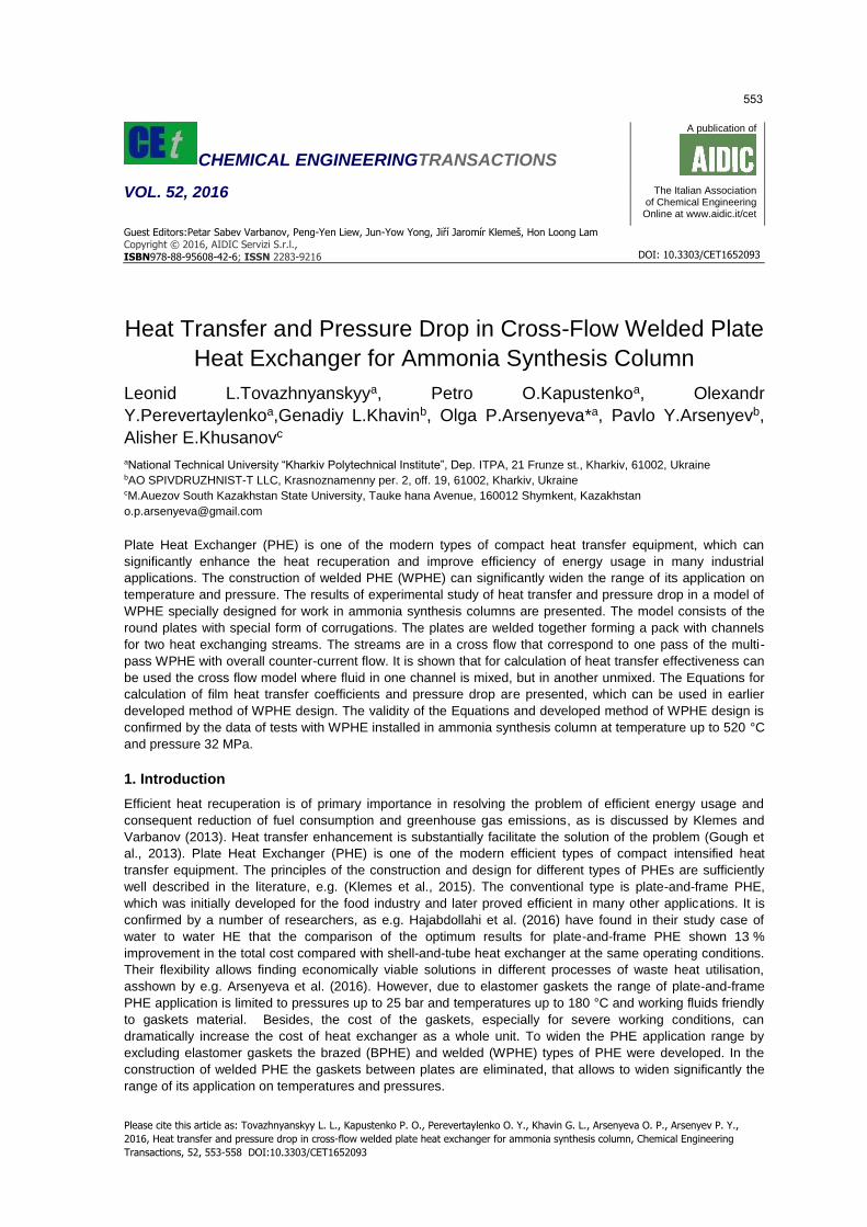
The WPHE developed for work in high pressure shell of ammonia synthesis column consist of a stack of round
plates with special form of corrugations, depicted in Figure 1. The plates are welded together to form a
number of channels for cold and hot streams exchanging heat. The welded collectors of special design are
organizing multi pass movement of both streams with overall counter current flow. The movement of two
streams in one pass block is cross flow. Compare to the flow of streams in conventional plate-and-frame PHE
there is significant difference. From hydraulic point of view the stream is entering the channel through almost
full cross section, while in channels of plate-and-frame PHE it is entering from distribution collector of small
diameter compare to channel width. It causes much smaller local hydraulic resistance at the port zone of
WPHE and ensures even flow distribution across channel width. But for the heat transfer cross flow of streams
causes the reduction of mean temperature difference compare to counter flow in one pass of plate-and-frame
PHE. The overall counter flow in WPHE is making this loss in mean temperature difference smaller, but still
this cross flow feature for individual passes should be accounted in correct PHE design. The available
literature data are not directly applicable, as the level of fluid mixing across PHE channel is not known.
2. Experimental model and test rig
The heat transfer and pressure drop in WPHE were investigated experimentally using the model consisted of
15 plates representing the block of plates in one pass of WPHE. The plates are forming 14 channels, in 7 of
which the hot stream is directed and in other 7 channels is directed the cold stream. The geometrical forms of
the channels for hot and cold fluids are different. For the cold stream the channel is formed by one plate with
most of the corrugations (at 2/3 plate area) directed along the main flow direction. The adjacent plate has
herringbone corrugation direction with angle 60 degrees to main flow direction. Resulting average corrugation
angle in this area is 30 º. At the remaining 1/3 of plate area the angle of corrugations to flow direction is 60 º
on both adjacent plates. The average angle of corrugations to flow direction is β2=40 º. Such form of
corrugations is made to facilitate the discharge of possible dust in the synthesis gas stream after catalyser,
which can appear with catalyser aging. The average angle of corrugations in another channel for hot stream is
equal to β1=50 º. The main geometrical parameters of the tested model, plate corrugations and inter-plate
channels are presented in Table 1.
Table 1: Table title (Style: CET-table-title)
Total heat transfer surface area, Fa, m2 4.2
Number of plates, Np 15
Heat transfer surface area of one plate, Fp,m2 0.32
Cross section area of one channel, fch, m2 0.0022
Plate outside diameter, Do, m 0.626
Plate thickness, δw, m 0.001
Plate metal AISI 304
Heat conductivity of the wall, λw, W/(m K) 16
Corrugations height, b, m 0.004
Corrugations pitch, S, m 0.018
Average channel width, Wch, m 0.55
Equivalent diameter of channel, de, m 0.008
Average corrugations angle to main flow direction: For
hot stream, β1, degrees
For cold stream, β2,degrees
50
40
The width of channel entrance (exit), Wenx, m 0.4
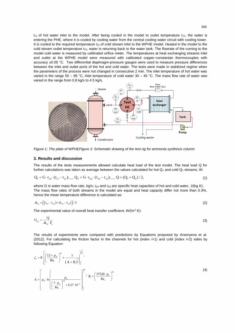
The thermal and hydraulic characteristics of the WPHE model were measured at specially developed test rig
with water as test fluid for both streams, schematically shown in Figure 2. The testing fluid is distilled water. It
is pumped from water tank to the tubular heat exchanger, where is heated by steam to required temperature
554
t11 of hot water inlet to the model. After being cooled in the model to outlet temperature t12, the water is
entering the PHE, where it is cooled by cooling water from the central cooling water circuit with cooling tower.
It is cooled to the required temperature t21 of cold stream inlet to the WPHE model. Heated in the model to the
cold stream outlet temperature t22, water is returning back to the water tank. The flowrate of the coming to the
model cold water is measured by calibrated orifice meter. The temperatures at heat exchanging streams inlet
and outlet at the WPHE model were measured with calibrated copper-constantan thermocouples with
accuracy ±0.05 °C. Two differential diaphragm-pressure gauges were used to measure pressure differences
between the inlet and outlet ports of the hot and cold water. The tests were made in stabilized regime when
the parameters of the process were not changed in consecutive 2 min. The inlet temperature of hot water was
varied in the range 55 – 85 °C, inlet temperature of cold water 30 – 45 °C. The mass flow rate of water was
varied in the range from 0.8 kg/s to 4.5 kg/s.
Figure 1: The plate of WPHEFigure 2: Schematic drawing of the test rig for ammonia synthesis column
3. Results and discussion
The results of the tests measurements allowed calculate heat load of the test model. The heat load Q for
further calculations was taken as average between the values calculated for hot Q1 and cold Q2 streams, W:
1 p1 11 12 2 p2 22 21 1 2Q G c (t t ); __ Q G c (t t ); __ Q (Q Q ) / 2, (1)
where G is water mass flow rate, kg/s; cp1 and cp2 are specific heat capacities of hot and cold water, J/(kg K).
The mass flow rates of both streams in the model are equal and heat capacity differ not more than 0.3%,
hence the mean temperature difference is calculated as:
m 11 22 12 21t t t (t t ) / 2 (2)
The experimental value of overall heat transfer coefficient, W/(m2 K):
ex
m a
QU
t F
(3)
The results of experiments were compared with predictions by Equations proposed by Arsenyeva et al.
(2012). For calculating the friction factor in the channels for hot (index i=1) and cold (index i=2) sides by
following Equation:
1
1212
2
3
2
12 18
Re
ii
ii i
p
A B
,
16
54 0.9
53
ln7
0.27 10Re
ii i
i
i
pA p
p
; 16
137530
Re
ii
i
pB
(4)
555
where p1i, p2i, p3i, p4i, p5iare the parameters defined by channel corrugation form.
1 exp 0.15705 i ip ; 2
23
i
ip;
3 2
1exp
180
ii
i
p ;
2.63 0.01
4 0.061 0.69 1 1 0.9i i i ip tg
;
5 110
iip
γi=2b/S is the corrugation doubled plate spacing b to corrugation pitch S ratio; βi is the corrugations inclination
angle, degrees; Rei=widei/ µiis the Reynolds number; de is the equivalent diameter of the channel, de = 2b,
m; wi is the stream velocity in the channel, m/s; µi is the dynamic viscosity of fluid, Pa∙s; iis the density of the
fluid, kg/m3.
The film heat transfer coefficients are estimated using for hot (1) and cold (2) sides the following relation:
3 0.1476
7
wi
0.065 Re Pr
ci i ii i iNu
F (5)
Where µi and μwi are the dynamic viscosities for the stream and wall temperatures, Pa∙s; Nu=hide/i is
the Nusselt number; iis the thermal conductivity of the fluid, W/(m·K); hi is the film heat transfer coefficient,
W/(m2·K); Pri is the Prandtl number; ζi is the friction factor accounting for total pressure losses in the channel,
calculated by Equation (2); ψi is the share of pressure loss due to friction on the wall in total loss of pressure;
Fx is the coefficient of surface area enlargement due to corrugation.
The value of ψi is estimated according to relation:
1.75
1 380 / ( )i iA tg ;
0.15 sin( )
1 1
11
Re
R
Re
e
i
i
ii
i i i
i i
A at A
at A
(6)
The calculated value of overall heat transfer coefficient is determined as:
1
wcl
1 2 w
1 1U
h h
(7)
The influence of fluid velocity on overall heat transfer coefficient is shown on graph in Figure 3. There
presented experimental and calculated values. The calculated values are somewhat higher than experimental
ones, but the discrepances are not exciding +8 %. Beside some experimental error it can be explained by
reduction of heat transfer effectiveness due to cross flow. In Figure 4 is presented the dependance of the
WPHE model heat transfereffectivness ε=(t11-t12)/(t11-t21) from the number of heat transfer units (NTU),
expressed through calculated overall heat transfer coefficient Ucl by following Equation:
a cl
p1
F UNTU
G c
(8)
The ε-NTU experimental values are situated below ε-NTU values calculated by Equation for counter-current
flow, but can be approximated on a safe side by ε-NTU relation for cross flow with one fluid mixed another
unmixed (see Shah and Sekulic, 2003):
1 exp R NTU1 exp
R
(9)
where R=G1.cp1/( G2
.cp2). In our case R=1, but it can be approximated also for other cases with R<1. Using this
relation (Eq.9) the ε-NTU method proposed by Arsenyeva et al. (2016) can be used for calculation of
considered multipass WPHEs.
556
Figure 3: The influence of flow welocity Figure 4: The ε-NTU relation for WPHE
on overall heat transfer coefficient: model: 1- experiment; 2 – counter-current;