THE AM RAIA9ciaixoF,mgcliwAt,*NpiNEERS 98-GT-28 The,Eoaety not be be,Les Ietor or advanced n.papers or,discussion *roeerteagsof the:Sooesty , .orpftelevisiens xtr Sections, or Printed in its pi ons Disobasian isprinted :lithe.' fiapublished in an ASME'49tenal. AuthaFizati0k4 61 3h4tb6i? for internel.or personal 'Usaitgranted ,:to libeAries and otherttsOs registered with the Coplright qearanCe;:Center (CCC):pEo‘ed S3fartiOle or $4/page is paid'td‘CC,C;t22.ildieeiredi(Dr:; ,Deni:reis, M4 ,01913. Requests for Special*rrniisionsor bulk reproditiliii; .. , shduld be addressed to the ASME Tebbnical Publishing Department. Copyright ®1998 by ASME All Riy Reserved Printed in U.S.A. HEAT TRANSFER COEFFICIENT MEASUREMENTS OF FILM-COOLING HOLES WITH EXPANDED EXITS M. Gritsch, A. Schulz, and S. Wittig Lehrstuhl and Institut fiir Thermische StrOmungsmaschinen Universitat Karlsruhe (T.H.) Kaiserstr. 12, 76128 Karlsruhe, Germany ABSTRACT Detailed measurements of heat transfer coefficients in the nearfield of three different film-cooling holes are presented. The hole geometries investigated include a cylindrical hole and two holes with a diffuser shaped exit portion (i.e. a fan- shaped and a laidback fanshaped hole). They were tested over a range of blowing ratios M=0.25...1.75 at an exter- nal crossflow Mach number of 0.6 and a coolant-to-mainflow density ratio of 1.85. Additionally, the effect of the internal coolant supply Mach number is addressed. Temperatures of the diabatic surface downstream of the in- jection location are measured by means of an infrared cam- era system. They are used as boundary conditions for a finite element analysis to determine surface heat fluxes and heat transfer coefficients. The superposition method is ap- plied to evaluate the overall film-cooling performance of the hole geometries investigated. As compared to the cylindrical hole, both expanded holes show significantly lower heat transfer coefficients down- stream of the injection location, particularly at high blowing ratios. The laidback fanshaped hole provides a better lateral spreading of the injected coolant than the fanshaped hole which leads to lower laterally averaged heat transfer coeffi- cients. Coolant passage crossflow Mach number affects the flowfield of the jet being ejected from the hole and, there- fore, has an important impact on film-cooling performance. NOMENCLATURE Film-cooling hole diameter Coolant-to-mainflow density ratio Local heat transfer coefficient Local heat transfer coefficient at 0=0 , Eq. (1) Coolant-to-mainflow momentum flux ratio Film-cooling hole length measured along the hole centerline M Ma NHFR ReD Tt Trey Tu. x Greek a 599 77 8 Blowing ratio Mach number Net heat flux reduction, Eq. (3) Surface heat flux Reynolds number based on film-cooling hole diameter Total temperature Recovery temperature Turbulence intensity Streamwise distance from downstream edge of the film-cooling hole Lateral distance from centerline of the film-cooling hole Angle of hole inclination Boundary layer thickness, 99% point Local film-cooling effectiveness, Eq. (2) Dimensionless temperature ratio, Eq. (4) Subscripts 0 No injection case c Coolant conditions m Mainflow conditions AW Adiabatic wall conditions (q. "=0) Diabatic wall conditions (q" 00) Superscripts laterally averaged value spatially averaged value INTRODUCTION Improving the performance of gas turbines can be achieved by increasing the turbine inlet temperature. This requires highly effective cooling techniques to maintain the temper- ature of the components in contact with the hot gases at acceptable levels. Film-cooling is widely used to protect gas turbine blades from hot gases by injecting compressor bleed air through discrete holes in the blade surface. D DR h hf L Presented at the International Gas Turbine & Aeroengine Congress & Exhibition Stockholm, Sweden — June 2–June 5, 1998 Downloaded From: http://proceedings.asmedigitalcollection.asme.org/pdfaccess.ashx?url=/data/conferences/asmep/82036/ on 04/08/2018 Terms of Use: http://www.asme.org/abo
Transcript
THE AM RAIA9ciaixoF,mgcliwAt,*NpiNEERS 98-GT-28
The,Eoaety not bebe,Les Ietor or advanced n.papers or,discussion *roeerteagsof the:Sooesty , .orpftelevisiens xtrSections, or Printed in its pi ons Disobasian isprinted :lithe.' fiapublished in an ASME'49tenal. AuthaFizati0k4613h4tb6i?for internel.or personal 'Usaitgranted ,:to libeAries and otherttsOs registered with the Coplright qearanCe;:Center (CCC):pEo‘edS3fartiOle or $4/page is paid'td‘CC,C;t22.ildieeiredi(Dr:; ,Deni:reis, M4 ,01913. Requests for Special*rrniisionsor bulk reproditiliii;.. ,shduld be addressed to the ASME Tebbnical Publishing Department.
Copyright ®1998 by ASME
All Riy Reserved Printed in U.S.A.
HEAT TRANSFER COEFFICIENT MEASUREMENTS OFFILM-COOLING HOLES WITH EXPANDED EXITS
M. Gritsch, A. Schulz, and S. WittigLehrstuhl and Institut fiir Thermische StrOmungsmaschinen
Detailed measurements of heat transfer coefficients in thenearfield of three different film-cooling holes are presented.The hole geometries investigated include a cylindrical holeand two holes with a diffuser shaped exit portion (i.e. a fan-shaped and a laidback fanshaped hole). They were testedover a range of blowing ratios M=0.25...1.75 at an exter-nal crossflow Mach number of 0.6 and a coolant-to-mainflowdensity ratio of 1.85. Additionally, the effect of the internalcoolant supply Mach number is addressed.
Temperatures of the diabatic surface downstream of the in-jection location are measured by means of an infrared cam-era system. They are used as boundary conditions for afinite element analysis to determine surface heat fluxes andheat transfer coefficients. The superposition method is ap-plied to evaluate the overall film-cooling performance of thehole geometries investigated.
As compared to the cylindrical hole, both expanded holesshow significantly lower heat transfer coefficients down-stream of the injection location, particularly at high blowingratios. The laidback fanshaped hole provides a better lateralspreading of the injected coolant than the fanshaped holewhich leads to lower laterally averaged heat transfer coeffi-cients. Coolant passage crossflow Mach number affects theflowfield of the jet being ejected from the hole and, there-fore, has an important impact on film-cooling performance.
NOMENCLATUREFilm-cooling hole diameterCoolant-to-mainflow density ratioLocal heat transfer coefficientLocal heat transfer coefficient at 0=0 , Eq. (1)Coolant-to-mainflow momentum flux ratioFilm-cooling hole length measured alongthe hole centerline
MMaNHFR
ReD
TtTreyTu.x
Greeka599778
Blowing ratioMach numberNet heat flux reduction, Eq. (3)Surface heat fluxReynolds number based on film-coolinghole diameterTotal temperatureRecovery temperatureTurbulence intensityStreamwise distance from downstreamedge of the film-cooling holeLateral distance from centerline of thefilm-cooling hole
Angle of hole inclinationBoundary layer thickness, 99% pointLocal film-cooling effectiveness, Eq. (2)Dimensionless temperature ratio, Eq. (4)
Superscriptslaterally averaged valuespatially averaged value
INTRODUCTIONImproving the performance of gas turbines can be achievedby increasing the turbine inlet temperature. This requireshighly effective cooling techniques to maintain the temper-ature of the components in contact with the hot gases atacceptable levels. Film-cooling is widely used to protectgas turbine blades from hot gases by injecting compressorbleed air through discrete holes in the blade surface.
DDRhhf
L
Presented at the International Gas Turbine & Aeroengine Congress & ExhibitionStockholm, Sweden — June 2–June 5, 1998
Downloaded From: http://proceedings.asmedigitalcollection.asme.org/pdfaccess.ashx?url=/data/conferences/asmep/82036/ on 04/08/2018 Terms of Use: http://www.asme.org/about-asme/terms-of-use
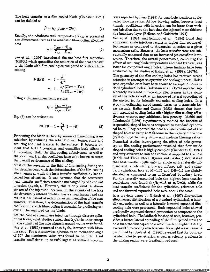
The heat transfer to a film-cooled blade (Goldstein 1971)can be defined as
q" = hf (TAw –Tw) (1)
Usually, the adiabatic wall temperature TAW is presentednon-dimensionalized as the adiabatic film-cooling effective-ness
TAW — Tt,m
Tt,c Tt,m.
Sen et al. (1994) introduced the net heat flux reduction(NHFR) which quantifies the reduction of the heat transferto the blade with film-cooling as compared to without film-cooling
NHFR = 1–
- 1 h f (TAW TW) ho – Tw)
Using a dimensionless temperature
= Tt ,m – Tt,c8 Tt,m – Tw
Eq. (3) can be written as
NHFR = 1– ho
— (1 –778)h
Protecting the blade surface by means of film-cooling is es-tablished by reducing the adiabatic wall temperature andreducing the heat transfer to the surface. It becomes ev-ident that NHFR combines and quantifies both effects offilm-cooling. Both the film-cooling effectiveness as well asthe local heat transfer coefficient have to be known to assessthe overall performance of film-cooling.Most of the research in the field of film-cooling during thelast decades dealt with the determination of the film-coolingeffectiveness i , while the heat transfer coefficient h f has re-ceived less attention. It was assumed that the convectiveheat transfer coefficient remains unchanged by the coolantinjection (Iv =h0). However, this is only valid far down-stream of the injection location. In the vicinity of the holethe drastically altered flowfield has a strong impact and canresult in a substantial reduction or augmentation of the heattransfer. Therefore, the determination of the heat transfercoefficient hf with film-cooling is essential for predicting theoverall thermal load on the blade.For the case of streamwise injection through discrete cylin-drical holes, most studies stated that hf /h o is unity exceptin the vicinity of the hole where increased values were found.Hay et al. (1985) reported that hilh o increases with blow-ing ratio. For a streamwise injection at an inclination angleof 35° the maximum value was found to be 1.35. Heattransfer coefficients up to 60% higher as without injection
were reported by Liess (1975) for near-hole locations at ele-vated blowing ratios. At low blowing ratios, however, heattransfer coefficients with injection can be lower than with-out injection due to the fact that the injected mass thickensthe boundary layer (Eriksen and Goldstein 1974).Sen et al. (1994) and Schmidt et al. (1994) found thatcompound angle injection results in higher film-cooling ef-fectiveness as compared to streamwise injection at a givenmomentum ratio. However, the heat transfer rates are sub-stantially enhanced due to an increased jet-crossflow inter-action. Therefore, the overall performance, combining theeffects of reducing blade temperature and heat transfer, waslower for compound angle holes. These findings have beenconfirmed by the studies of Ekkad et al. (1997a, 1997b).The geometry of the film-cooling holes has received recentattention in attempts to optimize the cooling process. Holeswith expanded exits have been shown to be superior to stan-dard cylindrical holes. Goldstein et al. (1974) reported sig-nificantly increased film-cooling effectiveness in the vicin-ity of the hole as well as an improved lateral spreading ofthe ejected jet for laterally expanded cooling holes. In astudy investigating aerodynamic losses on a transonic lin-ear cascade, Haller and Camus (1983) showed that later-ally expanded cooling holes offer higher film-cooling effec-tiveness without any additional loss penalty. Maldd andJakubowski (1986) experimentally studied the benefits oftrapezoidal shaped holes as compared to standard cylindri-cal holes. They reported the heat transfer coefficient of theshaped holes to be up to 20% lower in the vicinity of the hole(x/D<50), particularly at low and medium blowing ratios.Numerical studies investigating the effect of hole geome-try on film-cooling performance revealed that flow insideshaped cooling holes is highly complex (Giebert et al. 1997)and very sensitive to how the coolant is supplied to the hole(Kohli and Thole 1997). Hyams and Leylek (1997) statedthat heat transfer coefficients for a hole with a laterally dif-fused exit, a hole with a forward diffused exit, and a stan-dard cylindrical hole at M=1.25 and DR=1.6 are slightlyelevated as compared to an undisturbed boundary layer.For the laterally expanded hole the highest heat transfercoefficients were found (hf /h0=1.3 at x/D=2), while theheat transfer coefficients for the cylindrical reference holeand the forward expanded hole were about the same .In a previous paper by Gritsch et al. (1997) film-coolingeffectiveness distributions of a standard cylindrical, a later-ally expanded as well as a laterally-forward expanded film-cooling hole were presented. Both expanded holes showedprofoundly improved thermal protection as compared to thecylindrical hole. The laidback fanshaped hole, however, pro-vides a better lateral spreading of the film ejected from thehole than the fanshaped hole which leads to higher laterallyaveraged film-cooling effectiveness. Flowfield measurementsperformed by Thole et al. (1996) revealed that for both ex-panded holes jet penetration as well as velocity gradients inthe mixing region were drastically reduced.
– (2)
(3)
(4)
(5)
2
Downloaded From: http://proceedings.asmedigitalcollection.asme.org/pdfaccess.ashx?url=/data/conferences/asmep/82036/ on 04/08/2018 Terms of Use: http://www.asme.org/about-asme/terms-of-use
290 K0.25 ...1.750.540, 0.3, 0.60.6up to 2.5-1050.75-105
0.5<2 %1%
Test section Windows
TAB. 1: Operating conditions of the film-cooling test rig
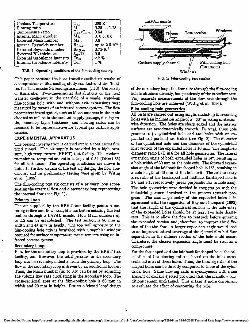
This paper presents the heat transfer coefficient results ofa comprehensive film-cooling study conducted at the 'Insti-tut ffir Thermische StrOmungsmaschinen' (ITS), Universityof Karlsruhe. Two-dimensional distributions of the heattransfer coefficient in the nearfield of a single, scaled-upfilm-cooling hole with and without exit expansions weremeasured by means of an infrared camera system. The flowparameters investigated, such as Mach numbers in the mainchannel as well as in the coolant supply passage, density ra-tio, boundary layer thickness, and blowing ratios can beassumed to be representative for typical gas turbine appli-cations.EXPERIMENTAL APPARATUSThe present investigation is carried out in a continuous flowwind tunnel. The air supply is provided by a high pres-sure, high temperature (HPHT) test facility. The coolant-to-mainflow temperature ratio is kept at 0.54 (DR=1.85)for all test cases. The operating conditions are shown inTable 1. Further details of the test rig design, the flow con-ditions, and on preliminary testing were given by Wittiget al. (1996).The film-cooling test rig consists of a primary loop repre-senting the external flow and a secondary loop representingthe internal flow (see Fig. 1).Primary Loop
The air supplied by the HPHT test facility passes a me-tering orifice and flow straighteners before entering the testsection through a LAVAL nozzle. Flow Mach numbers upto 1.2 can be established. The test section is 90 mm inwidth and 41 mm in height. The top wall opposite to thefilm-cooling hole exit is furnished with a sapphire windowrequired for surface temperature measurements using an in-frared camera system.Secondary Loop
Flow for the secondary loop is provided by the HPHT testfacility, too. However, the total pressure in the secondaryloop can be set independently from the primary loop. Theflow in the secondary loop is driven by an additional blower.Thus, the Mach number (up to 0.6) can be set by adjustingthe volume flow rate circulating in the secondary loop. Thecross-sectional area at the film-cooling hole is 60 mm inwidth and 20 mm in height. Due to a 'closed loop' design
LAVAL nozzle
Coolant supply channel
Film-cooling hole(D= 10mm)
WindowsFIG. 1: Film-cooling test section
of the secondary loop, the flow rate through the film-coolinghole is obtained directly, independently of the crossflow rate.Very accurate measurements of the flow rate through thefilm-cooling hole are achieved (Wittig et al. 1996).Film-cooling hole geometries
All tests are carried out using single, scaled-up film-coolingholes with an inclination angle of a=30° injecting in stream-wise direction. The holes are sharp edged and the interiorsurfaces are aerodynamically smooth. In total, three holegeometries (a cylindrical hole and two holes with an ex-panded exit portion) are tested (see Fig. 2). The diameterof the cylindrical hole and the diameter of the cylindricalinlet section of the expanded holes is 10 mm The length-todiameter ratio L/D is 6 for all hole geometries. The lateralexpansion angle of both expanded holes is 14°, resulting ina hole width of 30 mm at the hole exit. The forward expan-sion angle of the laidback fanshaped hole is 15°, resulting ina hole length of 40 mm at the hole exit. The exit-to-entryarea ratio of the fanshaped and laidback fanshaped hole is3.0 and 3.1, respectively (areas perpendicular to hole axis).The hole geometries were decided in cooperation with theindustrial partners involved in the present research pro-gram. The chosen geometry of the expanded holes is inagreement with the suggestion of Hay and Lampard (1995)that the length of the cylindrical section at the hole entryof the expanded holes should be at least two hole diame-ters. This is to allow the flow to reattach before enteringthe expanded section and, therefore, to improve the diffu-sion of the the flow. A larger expansion. angle would leadto an improved lateral coverage of the ejected film but flowseparation in the diffuser section of the hole could occur.Therefore, the chosen expansion angle must be seen as acompromise.For the fanshaped and the laidback fanshaped hole, the cal-culation of the blowing ratio is based on the inlet cross-sectional area of these holes. Thus, the blowing ratio of theshaped holes can be directly compared to those of the cylin-drical hole. Same blowing ratio is synonymous with sameamount of coolant ejected provided that the mainflow con-ditions remain unchanged. This makes it more convenientto evaluate the effect of contouring the hole.
3
Downloaded From: http://proceedings.asmedigitalcollection.asme.org/pdfaccess.ashx?url=/data/conferences/asmep/82036/ on 04/08/2018 Terms of Use: http://www.asme.org/about-asme/terms-of-use
(c)14 °
xID15 °
(b)14 °
-411NP,
IP""
\apk7
•IP
30
8
n
• •
11.1.1.1*/• \ii,•
• •• •Film-cooling ho
Copper block
Internal water cooling
High temperatureplastics
FIG. 2: Cylindrical, fanshaped, and laidback fanshaped film-cooling hole geometries
IR camera
FIG. 3: Heat transfer test plate
MEASUREMENT TECHNIQUEThe superposition approach to film-cooling is an acceptedmethod of dealing with problems of varying wall tempera-tures and was first described by Metzger and Fletcher (1971)and Choe et al. (1974). It arises from the linearity andhomogeneity of the simplified boundary layer differentialequations. In this case, the heat transfer is usually definedas
qrr = h (Tt,m – Tw) (6)
Eckert (1984) showed that this approach is equivalent toGoldstein's approach (Eq. 1). They can be combined to
ho h „
= i— – no) (7)ho
The findings of Metzger and Fletcher (1971) who showedthe linearity of h with 0 were extended by Forth et al.(1985) to compressible, variable properties flow situations.When plotting h/ho versus 0, the axes intercepts are hf /h oat 0=0 and 1/n at h/h0 =0. To determine hf and 77, at leasttwo data sets at two different 0 are required.Several techniques for determining the local heat transfercoefficient have been applied in the past. Transient mea-suring techniques like liquid crystals (Shen et al. 1991)
or thin film heat flux gauges (Teekarara et al. 1989) wereused in a short duration blow-down wind tunnel. Resultsfrom mass transfer experiments such as swollen polymersurface in conjunction with laser holographic interferome-try (Goldstein and Taylor 1982, Hay et al. 1993) as well asnaphtalene sublimation (Cho and Goldstein 1995, Hiringet al. 1995) were believed to be transferable to heat trans-fer problems using the heat/mass transfer analogy. Erik-sen and Goldstein (1974), Ligrani et al. (1991), and Senet al. (1994) used electrical heater foils to apply a wall heatflux in steady state experiments. This technique has alsobeen used at the ITS before (Scherer et al. 1991, Martinyet al. 1997). The major drawback of the heater foils isthat they can not be used at elevated temperatures. Thus,experiments using heater foils were performed at coolant-to-mainflow density ratios close to unity. For the determina-tion of the heat transfer coefficient, however, it is importantto perform the heat transfer experiments at the same flowconditions as the adiabatic wall experiments. This can beachieved by keeping the coolant-to-mainflow temperatureratio unchanged and varying 0 only by varying the walltemperature. Therefore, another technique of determiningthe local heat transfer coefficient has been applied in thepresent investigation.The test plate used for acquiring heat transfer coefficientsconsists of a copper block which is maintained at a constanttemperature by internal water cooling (Fig. 3). The copperblock is topped with a 3mm layer of a high temperatureplastic (TECAPEK) with a thermal conductivity of 0.21W/mK and a maximum operating temperature of about570 K to reduce heat conduction in streamwise and lateraldirection. Surface temperatures are measured by means ofan AGEMA Thermovision 870 IR camera system.The IR camera system provides a two-dimensional distri-bution of the temperature on the plate surface. The im-age of the test plate surface is digitized into an array of140x140 pixels. Accounting for the optical setup used withthe IR camera a spatial resolution 0.8mm x 0.8mm per pixelcan be achieved. The test plate surface is covered by blackpaint of a known emissivity of 0.95. Seven thermocouples
lyii-rsce;r-hehe.tntjet
thein
6tedsur-..8,
4
Downloaded From: http://proceedings.asmedigitalcollection.asme.org/pdfaccess.ashx?url=/data/conferences/asmep/82036/ on 04/08/2018 Terms of Use: http://www.asme.org/about-asme/terms-of-use
distributed on the plate surface are used for an in situ cal-ibration of the lR, camera system to increase the accuracyof the temperature measurements. Details of the in situcalibration procedure are given by Martiny et al. (1996).A finite element analysis is performed to calculate the threedimensional temperature distribution in the test plate andto derive the heat flux 4" perpendicular to the surface ofthe test plate. The surface temperature of the test plateand the temperature of the water circulating through thecopper block are used as boundary conditions for the finiteelement analysis. Using Eq. (6), the heat transfer coefficienth is calculated from the surface heat flux and freestream-to-wall temperature difference. Note that the mainfiow totaltemperature Tt,,,, in Eqns. (2), (3), (4) and (6) has to be re-placed by the recovery temperature T rec,„, for compressibleflows as investigated in the present study (Ma„.,=0.6).Finally, the heat transfer coefficient 11,1 is determined froma linear extrapolation according to Eq. (7). To perform thisextrapolation a second set of data at the same flow condi-tions but a different e is needed. It is obvious to use the walltemperature distribution for the adiabatic case presented ina previous paper (Gritsch et al. 1997) as the second dataset. The calculation procedure has to be performed for eachpixel of the IR camera image to receive a two-dimensionaldistribution of the heat transfer coefficient hf.
RESULTS AND DISCUSSIONThe results of the present investigation will be presented interms of two-dimensional heat transfer coefficient distribu-tions, as well as of laterally and spatially averaged local heattransfer coefficients. Local heat transfer coefficients 13.1 willalways be normalized using the heat transfer coefficients hoof the no blowing case at the same location. Note that h owas determined from preliminary tests with the film-coolingholes blocked. The results showed good agreement to heattransfer coefficients calculated from correlations for turbu-lent boundary layer heat transfer provided by Kays andCrawford (1980).Since changes in heat transfer due to coolant injection areexpected to be most distinct close to the hole the resultspresented will focus on the heat transfer coefficients in thevicinity of the hole (x/D<8). As a baseline case, a main-flow Mach number of Mam=0.6 and a coolant supply pas-sage Mach number of Mac=0.0 (i.e. plenum condition) havebeen chosen from the test matrix. For this flow configu-ration the effect of hole geometry and blowing ratio on lo-cal as well as laterally and spatially averaged heat transfercoefficient will be discussed. Further on, the effect of thecoolant supply passage Mach number on the heat transfercoefficient distribution will be presented for all hole geome-tries and compared to the baseline case. Additionally, thepresent heat transfer results will be combined with previ-ous film-cooling effectiveness results to evaluate the overallfilm-cooling performance of the holes investigated.The main contribution to uncertainty in calculating the heat
transfer coefficient hf is the fact that two data sets at iden-tical flow conditions (M, Mara , and Tc/Tra ) are needed todetermine Iv from a linear extrapolation. Particularly forthe cylindrical hole, the jet position relative to the wall isvery sensitive to slight variations of the blowing ratio at highblowing ratios. The uncertainty in setting the external andinternal Mach number as well as the blowing ratio is within3% and in setting the temperature ratio is 1.5%. The max-imum deviation of the temperatures measured by means ofthe IR camera system from the temperatures of the surfacethermocouples are less than 1.5 K (Martiny et al. 1996).Combining these uncertanties (Kline and McClintock 1953)results in an average uncertainty of 4% for the local andlaterally averaged heat transfer coefficient. The maximumuncertainty is calculated to be 9%.Local heat transfer distributions
Fig. 4 presents the local heat transfer coefficient ratioshf /ho in the nearfield of the cylindrical, the fanshaped, andthe laidback fanshaped hole at three different blowing ra-tios (M=0.5, 1.0, and 1.5). For the cylindrical hole, heattransfer coefficient ratios are very low in the centerline re-gion at the lowest blowing ratio. This is due to the factthat the velocity of the injected jet is much lower than ofthe freestream which reduces the heat transfer as comparedto the no blowing case. Additionally, the injected massthickens the boundary layer. At higher blowing ratios theinjected jet has separated from the surface. The enhancedjet-mainflow interaction leads to elevated heat transfer co-efficients off-centerline, particularly at z/D=0.5.
For the fanshaped hole, a profound decrease of the heattransfer coefficient level is found at elevated blowing ratiosas compared to the cylindrical hole. The increased cross-sectional area at the exit of these holes decreases the exitmomentum flux of the jet and, therefore, reduces the pen-etration of the jet into the mainflow as compared to stan-dard cylindrical holes, which becomes obvious particularlyat high blowing ratios. The injected coolant leads to lowernear-wall velocities and thickens the boundary layer as re-ported by Thole et al. (1996) who performed flowfield mea-surements using the same hole geometry as in the presentstudy. Both effects reduce the heat transfer level. Low heattransfer coefficients are found for all blowing ratios consid-ered.
The heat transfer coefficients downstream of the laidbackfanshaped hole are found to be similar to the fanshapedhole. The spreading of the low heat transfer region extendsfurther in z-direction as compared to the fanshaped hole.This agrees with the results of the film-cooling effectivenessmeasurements of Gritsch et al. (1997) where an increasedspreading of the jet exiting the laidback fanshaped hole wasreported. Contrary to the fanshaped hole, minimum heattransfer coefficients are found off-centerline at z/D=1.5 dueto the spreading of the coolant in the laidback portion ofthe hole.
Downloaded From: http://proceedings.asmedigitalcollection.asme.org/pdfaccess.ashx?url=/data/conferences/asmep/82036/ on 04/08/2018 Terms of Use: http://www.asme.org/about-asme/terms-of-use
Downloaded From: http://proceedings.asmedigitalcollection.asme.org/pdfaccess.ashx?url=/data/conferences/asmep/82036/ on 04/08/2018 Terms of Use: http://www.asme.org/about-asme/terms-of-use
-e- Ekkad et al. 1995 , M=1.0, 13.68- 61- Ekkad et al. 1995), M=1.0, 1=1.02- e- Hay et al. (1985), M=0.97, 13.94-0- Hay et al. (1985), M=1.4,1=1.96-41- Eriksen and Goldstein(1974), M=0.99, 1=0.98-6- Eriksen and Goldstein (1974), M=1.45, 1=2.10-•- Amman et al. (1990), M=1.0, 13.66-..- Amman et al. (1990), M=1.5,1=1.48- e- Goldstein and Taylor(1982), M=1.0,1=1.0--0- Goldstein and Taylor (1982), M=1.5,1=2.25
Laterally averaged heat transfer coefficients
To account for the lateral spreading of the jet local heattransfer coefficients are averaged across the lateral span(z/D=± 2.75) resulting in a laterally averaged heat transfercoefficient
z / D=2.75
hi ix /DI = 1
5.5 ho- (x1d,z1D)d(z1D) (8)
o z/ D=-2.75
To check the capability of the present measuring techniquelaterally averaged heat transfer coefficients for the cylindri-cal hole are compared to previously published data. To beconsistent with previous studies the local heat transfer co-efficient for this case is averaged for z/D=±1.5 to simulatea nominal s/D=3, which was used in most of the publishedstudies.
a s/D DR Man,Present study 30° - 1.85 0.6Ekkad et al. (1997b) 35° 4 0.98, 1.46 <0.1Hay et al. (1985) 35° 3 1.0 <0.1Eriksen and Goldstein (1974) 35° 3 1.0 <0.2Ammari et al. (1990) 35° 3 1.52 <0.1Goldstein and Taylor (1982) 35° 3 1.0 <0.1Most of the past studies looked at isothermal jet injection(DR=1.0) while a more realistic density ratio DR=1.85 isused in the present study. This makes it more difficult tocompare the present data to those from the literature. How-ever, when the momentum flux ratio I rather than the blow-ing ratio M is used as a scaling parameter, present resultsmatch well with previous results (Fig. 5).The laterally averaged heat transfer coefficient distribu-tions for the three holes studied are shown in Fig. 6. Forthe cylindrical hole, two different regimes can be detected.At low blowing ratios, hi/ho increases monotonically asx/D increases while at high blowing ratios hi/ho decreasesmonotonically. As one would expect, hi/ho tends towardsunity for high x/D. For both shaped holes, hf /ho increasesmonotonically as x/D increases. Near the injection locationhi/4 is very low.Fig. 7 presents the laterally averaged heat transfer coeffi-cient plotted versus blowing ratio at x/D=3 and 7. For thecylindrical hole, hi/ho increases monotonically with M. Athigh blowing ratios, hi/h o is profoundly increased as com-pared to both shaped holes. Minimum heat transfer coeffi-cients for both shaped holes are found at medium blowingratios. For all blowing ratios, however, hi/ho for the laid-back fanshaped hole is up to about 20% lower than for thefanshaped hole. The results for the shaped holes are con-sistent with the data reported from Makki and Jakubowski(1986) for trapezoidal holes at DR=1.6 and x/D=11 whichare added to the plot. Their results confirm that the heattransfer coefficients of shaped holes level are much loweras compared to the cylindrical hole. Minimum heat trans-fer coefficients were reported at medium blowing ratios ofabout M=1.
2 3 4 5 6 7 8
9
10streamwise distance , x/D
FIG. 5: Comparison of laterally averaged heat transfer coefficientshi /hp of the cylindrical hole to published data
Effect of coolant supply crossflow Mach number
Thus far, none of the film-cooling heat transfer studies re-ported have investigated the effect of a crossflow at the holeentry. A plenum, widely used to feed the film-cooling holes,is not necessarily a correct means to represent the internalcoolant supply passage of an airfoil. To evaluate the ef-fect of coolant supply passage crossflow three representativecrossflow conditions have been chosen from the test matrix.These comprise coolant passage Mach numbers Ma c=0.0(i.e. plenum condition), 0.3, and 0.6 at a nominal blowingratio of M=1.0. Results are presented in Fig. 8.For the cylindrical hole, coolant supply crossflow has onlya rather small effect on the laterally averaged heat trans-fer coefficient (about 10%), while for the shaped holes anincrease of up to 15% (fanshaped) and 30% (laidback fan-shaped) in hi /ho is found when the coolant supply crossflowMach number is raised from Ma c=0.0 to 0.6. Gritsch et al.(1997) reported an increase of the laterally averaged film-cooling effectiveness of up to 30% for the cylindrical and15-20% for the shaped holes at M=1.0 when Ma c is raisedfrom 0.0 to 0.6.For the cylindrical hole, flowfield measurements performedby Thole et al. (1997) showed that the ejected jet stayscloser to the surface at elevated coolant supply Mach num-bers which results in increased film-cooling effectiveness.For the heat transfer coefficients, the turbulence intensityinside the ejected jet, which is strongly affected by thecoolant supply Mach number, becomes an important issue,
7
Downloaded From: http://proceedings.asmedigitalcollection.asme.org/pdfaccess.ashx?url=/data/conferences/asmep/82036/ on 04/08/2018 Terms of Use: http://www.asme.org/about-asme/terms-of-use
-, _e_ fs, Mac4.0I -e- fs, Mac 0.3;•-•• .. fs, Mac .6 -! ..•.,,,_ Ib, Mac .0
1 1 -&- Ib, Mac .3 -• 1 -0- lb„Mac4.6
2 3 4 5 6
7
8streamwise distance, x/D
1
0.95*C"
0.9
0.85
0.8
0.7515a)
0.70
0.65
0.6>.
0.55
0.52 3 4 5 6
7
8streamwise distance, x/D
FIG. 6: Laterally averaged heat transfer coefficients hf /ho for thecylindrical, fanshaped and laidback fanshaped hole at Ma m =0.6,Ma c=0.0
2
3 4 5 6
7 8streamwise distance, x/D
FIG. 8: Effect of coolant supply passage Mach number Ma, onlaterally averaged heat transfer coefficient h .f/ho for the three holesat Mam =0.6, M=1.0
particularly for the shaped holes, where the jet covers nearlythe whole span ( see Fig. 4). Elevated turbulence.intensi-ties are found at increased coolant supply Mach numbersleading to increased heat transfer inside the jet and, sincejet covers nearly the whole span, to increased laterally aver-aged heat transfer coefficients. The jet ejected through thecylindrical hole, however, covers only a small part of thespan. Thus, the laterally averaged heat tranfer coefficientis dominated by the heat transfer coefficients outside the jetwhich are only slightly affected by the coolant supply. Theresults confirm that the way the coolant is supplied to thehole affects the behavior of the ejected jet as pointed out inan earlier study (Gritsch et al. 1997).
Spatially averaged heat transfer coefficients
Spatially averaged heat transfer coefficients are calculatedby averaging local heat transfer coefficients over the sur-face downstream of the injection location (x/D=2...8,
8
Downloaded From: http://proceedings.asmedigitalcollection.asme.org/pdfaccess.ashx?url=/data/conferences/asmep/82036/ on 04/08/2018 Terms of Use: http://www.asme.org/about-asme/terms-of-use
FIG. 9: Effect of blowing ratio M on spatially averaged heat transfer
coefficient hi iho for the three holes at Ma m =0.6, Ma c =0.0
z/D=±2.75)
hfh0
-6- f -hfho (old) d(x I D)- -
x1D=8
(9)x/D=2
These values hf /ho are plotted versus blowing ratio inFig. 9. The slope of the curves is similar to those in Fig. 7.The benefits of both shaped holes as compared to the cylin-drical hole become obvious at high blowing ratios. The heattransfer to the surface downstream of the shaped holes isonly 75% of the cylindrical hole. The slope of the curvesfor both shaped holes is about the same, the level for thelaidback fanshaped hole, however, is lower, particularly atlow blowing ratios.Overall film-cooling performance
To evaluate the overall performance of the film-cooling holegeometries studied results from the heat transfer coefficientas well as film-cooling effectiveness measurements are usedto calculate h/h0=f(e) and subsequently NHFR=f(0). Acenterline position (z/D=0) at x/D=7 is chosen to comparethe different hole geometries (Fig. 10). When looking at therange of practical relevance of 0=1...2, the performance ofthe fanshaped hole at medium to high blowing ratios is best(low h/ho and high NHFR). But also the cylindrical hole atlow to medium blowing ratios and the laidback fanshapedhole at medium to high blowing ratios provide reasonableprotection of the surface. The cylindrical hole at high blow-ing ratios as well as fanshaped and laidback fanshaped holesat low blowing ratios, however, show only poor performance.The improved off-centerline performance of the laidbackfanshaped hole as compared to the fanshaped hole becomesobvious when NHFR is plotted versus e (Fig. 11) at anoff-centerline position (x/D=7, z/D=1.5). This is due tothe improved lateral spreading of the jet exiting the holeas compared to the fanshaped hole. At this location, very
5
FIG. 10: Variation of NHFR with 0 for the three holes studied atx/D=7.0, z/D=0.0, Ma m=0.6, Mac =0.0
FIG. 11: Variation of NHFR with 0 for the three holes studied atx/D=7.0, z/D=1.5, Ma m=0.6, Mac=0.0
small NHFR values are found for the cylindrical hole in therelevant 0 range. For the highest blowing ratio (M=1.5),negative NHFR values indicate an ineffective use of coolant,since the injected jet is not able to reduce the surface tem-perature significantly but, on the other hand, augments theheat transfer to the surface.A spatially averaged net heat flux reduction
NHFR = 1 - hi (1 - _r7e) (10)
hois defined by using the spatially averaged heat transfer co-efficient hf /h0 and the spatially averaged film-cooling effec-tiveness ;1 calculated from the data of Gritsch et al. (1997).Setting 0 to a typical value of 1.5 for gas turbine blade ap-plications the key findings of the present investigation aresummarized in Fig. 12, which shows the effect of blowingratio on the overall performance of the three holes. The su-periority of both shaped holes at medium to high blowing
2
0
1 2 3temperature ratio, 8 = (T,-"1",)/(Tm-Tw)
0 1
9
Downloaded From: http://proceedings.asmedigitalcollection.asme.org/pdfaccess.ashx?url=/data/conferences/asmep/82036/ on 04/08/2018 Terms of Use: http://www.asme.org/about-asme/terms-of-use
-a- cylindrical-e- fanshaped
- laidback
0.7
0.6
0.5
0.4
0.3
0.2
0.1
0
-0.10 0.5 1
blowing ratio, M
the three holes at 0.1.5, Mam=0.6, Ma c =0.0FIG. 12: Effect of blowing ratio M on spatially averaged NHFR for
ratios due to the very poor overall film-cooling performanceof the cylindrical hole is clearly demonstrated. Optimumperformance for the shaped holes is achieved at blowingratios of M=1.0 (fanshaped hole) and M=1.5 (laidback fan-shaped hole). As mentioned before, the improved lateralspreading of the jet ejected through the laidback hole causesan increased net heat flux reduction as compared to the fan-shaped hole, particularly at high blowing ratios.CONCLUSIONSThe present experimental study was conducted to investi-gate the local heat transfer coefficient distribution in thenearfield of three film-cooling hole geometries including acylindrical hole and two holes with a diffuser shaped exitportion. Tests were performed at an engine like coolant-to-mainflow temperature ratio of 0.54 (DR=1.85) over a rangeof blowing ratios of M=0.25...1.75. Additionally, the ef-fect of internal coolant supply channel Mach number wasinvestigated. The results revealed that
• holes with expanded exits have profoundly lower heattransfer coefficients at elevated blowing ratios as com-pared to a cylindrical hole
• the laidback fanshaped hole provides better lateralspreading of the jet as compared to the fanshaped holeand, therefore, lower laterally averaged heat transfercoefficients
• combining the effects of reduced heat transfer coeffi-cients and increased film-cooling effectiveness, holeswith expanded exits provide significantly improvedoverall film-cooling performance at elevated blowingratios as compared to a cylindrical hole
• coolant crossflow Mach number has an impact on film-cooling performance in the near-hole region, particu-larly for the shaped holes. Therefore, crossflow at thehole entry side has to be taken into account whenmodelling film-cooling at engine representative condi-tions.
ACKNOWLEDGMENTSThis study was partly funded by the European Unionthrough grant by the Brite Euram program "Investigationof the Aerodynamics and Cooling of Advanced Engine Tur-bine Components" under Contract AER2-CT92-0044.
REFERENCES
Ammari, H. D., Hay, N., and Lampard, D. (1990). TheEffect of Density Ratio on the Heat Transfer CoefficientFrom a Film-Cooled Flat Plate . ASME Journal of Tur-bomachinery, Vol. 112, pp. 444 450.
Cho, H. H. and Goldstein, R. J. (1995). Heat (Mass)Transfer and Film Cooling Effectiveness With InjectionThrough Discrete Holes: Part II- On the Exposed Sur-face . ASME Journal of Turbomachinery, Vol. 117, pp.451-460.
Choe, H., Kays, W. M., and Moffat, R. J. (1974). TheSuperposition Approach to Film-Cooling . ASME Paper74-WA/GT-27.
Eckert, E. R. G. (1984). Analysis of Film Cooling andFull-Coverage Film Cooling of Gas Turbine Blades.ASME Journal of Engineering for Gas Turbines andPower, Vol. 106, pp. 206-213.
Ekkad, S. V., Zapata, D., and Han, J. C. (1997a). FilmEffectiveness over a Flat Surface with Air and CO2 In-jection through Compound Angle Holes Using a Tran-sient Liquid Crystal Image Method. ASME Journal ofTurbomachinery, Vol. 119, pp. 587-593.
Ekkad, S. V., Zapata, D., and Han, J. C. (1997b). HeatTransfer Coefficients over a Flat Surface with Air andCO2 Injection through Compound Angle Holes Using aTransient Liquid Crystal Image Method. ASME Jour-nal of Turbomachinery, Vol. 119, pp. 580-586.
Eriksen, V. L. and Goldstein, R. J. (1974). Heat Trans-fer and Film Cooling Following Injection Through In-clined Circular Tubes. ASME Journal of Heat Trans-fer, Vol. 96, pp. 239-245.
Forth, C. J. P., Loftus, P. J., and Jones, T. V. (1985).The Effect of Density Ratio on the Film-Cooling of aFlat Plate . Heat Transfer and Cooling in Gas Turbines,AGARD-CP-390, Paper 10.
Giebert, D., Gritsch, M., Schulz, A., and Wittig, S.(1997). Film-Cooling from Holes with Expanded Ex-its: Comparison of Computational Results with Exper-iment. ASME Paper 97-GT-163.
Goldstein, R. J. (1971). Film Cooling . Advances in HeatTransfer, Vol. 7, pp. 321-379.
Goldstein, R. J., Eckert, E. R. G., and Burggraf, F.(1974). Effects of Hole Geometry and Density on Three-Dimensional Film Cooling. Mt. J. Heat Mass Trans-fer, Vol. 17, pp. 595-607.
1.5 2
atioa,owevf
thaz8s th).band
t a faare Siw into
g tier,e beep
ecentTolestan_
ofa
10
Downloaded From: http://proceedings.asmedigitalcollection.asme.org/pdfaccess.ashx?url=/data/conferences/asmep/82036/ on 04/08/2018 Terms of Use: http://www.asme.org/about-asme/terms-of-use
Goldstein, R. J. and Taylor, J. R. (1982). Mass Trans-fer in the Neighborhood of Jets entering a CrossfiowASME Journal of Heat Transfer, Vol. 104, pp. 715-721.
Gritsch, M., Schulz, A., and Wittig, S. (1997). AdiabaticWall Effectiveness Measurements of Film-Cooling Holeswith Expanded Exits. ASME Paper 97-GT-164.
Haller, B. R. and Camus, J. J. (1983). Aerodynamic LossPenalty Produced by Film Cooling Transonic TurbineBlades. ASME Paper 83-GT-77.
Häring, M., Mks, A., Harasgama, S. P., and Richter, J.(1995). Heat Transfer Measurements on Turbine AirfoilsUsing the Naphtalene Sublimation Technique. ASMEJournal of Turbomachinery, Vol. 117, pp. 432-439.
Hay, N. and Lampard, D. (1995). The Discharge Coeffi-cient of Flared Film Cooling Holes . ASME Paper 95-GT-15.
Hay, N., Lampard, D., and Macleod, N. (1993). TheSwollen Polymer Technique and its Use for Heat Trans-fer Investigations on Film Cooled Surfaces. Heat Trans-fer and Cooling in Gas Turbines, AGARD-CP-527, Pa-per 19.
Hay, N., Lampard, D., and Saluja, C. L. (1985). Effectsof Cooling Films on the Heat Transfer Coefficient on aFlat Plate With Zero Mainstream Pressure Gradient.ASME Journal of Engineering for Gas Turbines andPower, Vol. 107, pp. 104-110.
Hyams, D. G. and Leylek, J. H. (1997). A Detailed Anal-ysis of Film Cooling Physics Part III: Streamwise Injec-tion with Shaped Holes. ASME Paper 97-GT-271.
Kays, W. M. and Crawford, M. E. (1980). ConvectiveHeat and Mass Transfer. McGraw Hill, New York.
Kline, S. J. and McClintock, F. A. (1953). DescribingUncertainties in Single-Sample Experiments . Mechan-ical Engineering, Vol. 75, pp. 3-8.
Kohli, A. and Thole, K. A. (1997). A CFD Investigationon the Effects of Entrance Crossfiow Directions to Film-Cooling Holes. National Heat Transfer Conference, Aug.10-12, 1997, Baltimore, MD.
Liess, C. (1975). Experimental Investigation of FilmCooling With Ejection From a Row of Holes for theApplication to Gas Turbine Blades. ASME Journal ofEngineering for Power, Vol. 97, pp. 21-27.
Ligrani, P. M., Subramanian, C. S., Craig, D. W., andKaisuwan, P. (1991). Effects of Vortices with Differ-ent Circulations on Heat Transfer and Injectant Down-stream of a Single Film-Cooling Hole in a Turbu-lent Boundary Layer . ASME Journal of Heat Trans-fer, Vol. 113, pp. 79-90.
Makid, Y. H. and Jakubowski, G. (1986). An Experimen-tal Study of Film Cooling from Diffused TrapezoidalShaped Holes. AIAA Paper 86-1326.
Martiny, M., Schiele, R., Gritsch, M., Schulz, A., andWittig, S. (1996). In Situ Calibration for QuantitativeInfrared Thermography. QIRT'96 Eurotherm SeminarNo. 50, Stuttgart, Germany, Sept. 2-5, 1996.
Martiny, M., Schulz, A., Wittig, S., and Dilzer, M.(1997). Influence of a Mixing-Jet on Film Cooling .ASME Paper 97-GT-247.
Metzger, D. E. and Fletcher, D. D. (1971). Evaluation ofHeat Transfer for Film-Cooled Turbine Components .Journal of Aircraft, Vol. 8, pp. 33-38.
Scherer, V., Wittig, S., Morad, K., and Mikhael, N.(1991). Jets in a Crossfiow: Effects of Hole Spacingto Diameter Ratio on the Spatial Distribution of HeatTransfer. ASME Paper 91-GT-356.
Schmidt, D. L., Sen, B., and Bogard, D. G. (1994).Film Cooling with Compound Angle Holes: AdiabaticEffectiveness. ASME Paper 94-GT-312.
Sen, B., Schmidt, D. L., and Bogard, D. G. (1994). FilmCooling with Compound Angle Holes: Heat Transfer.ASME Paper 94-GT-311.
Shen, J. R., Ireland, P. T., Wang, Z., and Jones, T. V.(1991). Heat transfer coefficient enhancement in a gasturbine blade cooling passage due to film cooling holes.Turbomachinery: Latest Developments in a ChangingScene, Paper C 423/040, Proceedings of the Institutionof Mechanical Engineers.
Teekaram, A. J. H., Forth, C. J. P., and Jones, T. V.(1989). The Use of Foreign Gas to Simulate the Effectsof Density Ratios in Film Cooling. ASME Journal ofTurbonzachinery, Vol. 111, pp. 57-61.
Thole, K. A., Gritsch, M., Schulz, A., and Wittig, S.(1996). Flowfield Measurements for Film-Cooling Holeswith Expanded Exits. ASME Paper 96-GT-174.
Thole, K. A., Gritsch, M., Schulz, A., and Wittig, S.(1997). Effect of a Crossfiow at the Entrance to aFilm-Cooling Hole. ASME Journal of Fluids Engineer-ing, Vol. 119, pp. 533-541.
Wittig, S., Schulz, A., Gritsch, M., and Thole, K. A.(1996). Transonic Film-Cooling Investigations: Effectsof Hole Shapes and Orientations. ASME Paper 96-GT-222.
1 1
Downloaded From: http://proceedings.asmedigitalcollection.asme.org/pdfaccess.ashx?url=/data/conferences/asmep/82036/ on 04/08/2018 Terms of Use: http://www.asme.org/about-asme/terms-of-use