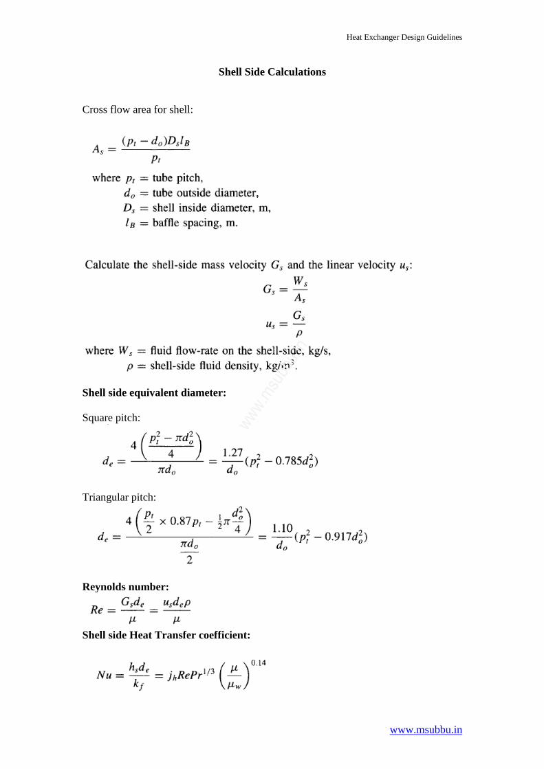
Shell Side Calculations Cross flow area for shell:
Shell side equivalent diameter: Square pitch:
Triangular pitch:
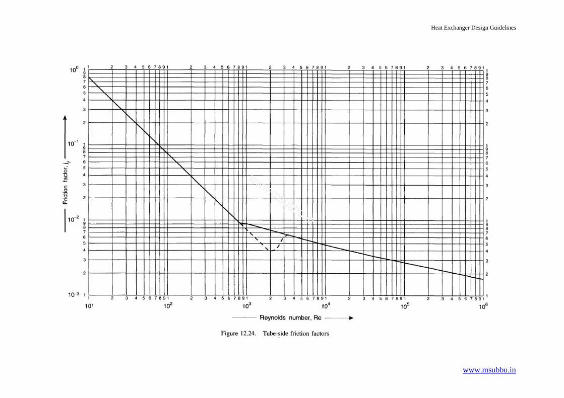
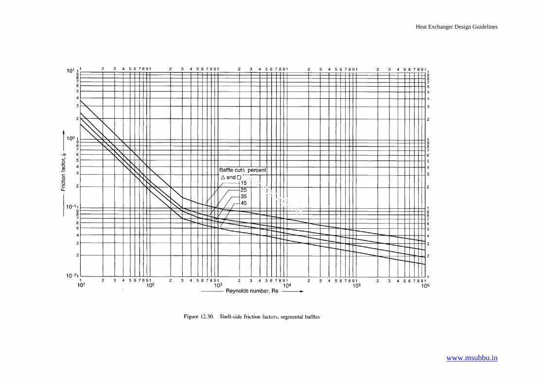
Reynolds number:
Shell side Heat Transfer coefficient:
ww
w.m
subbu.in
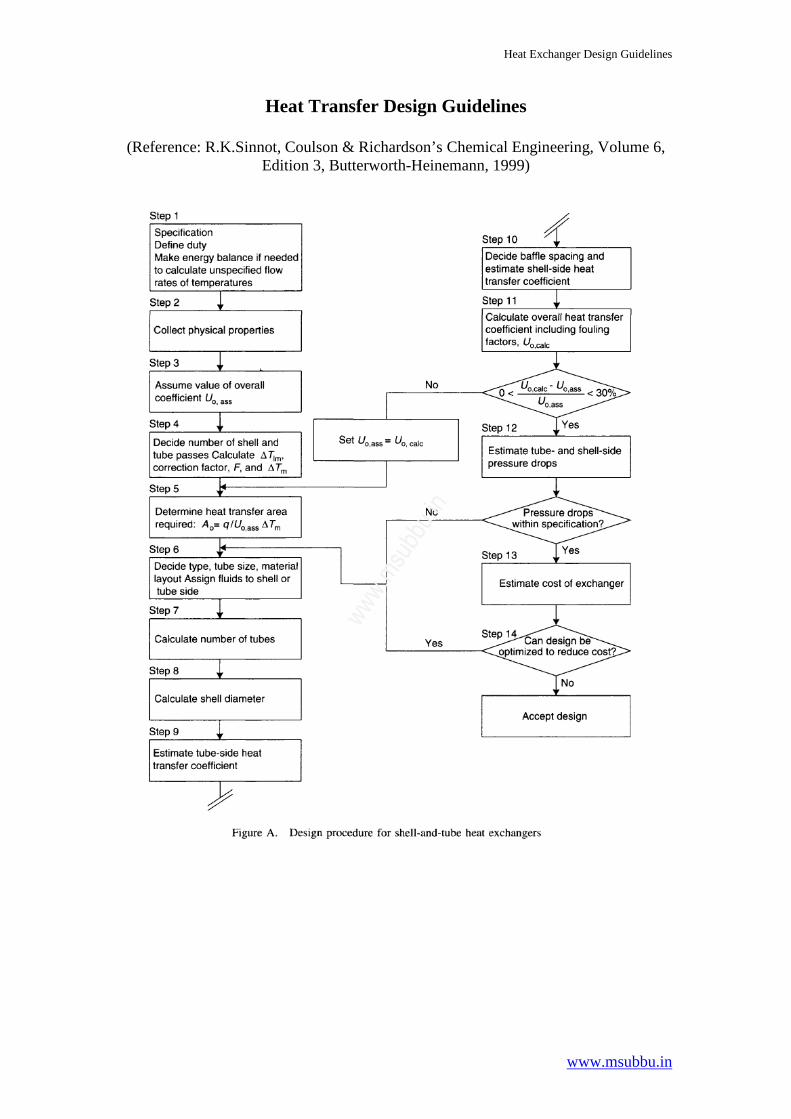
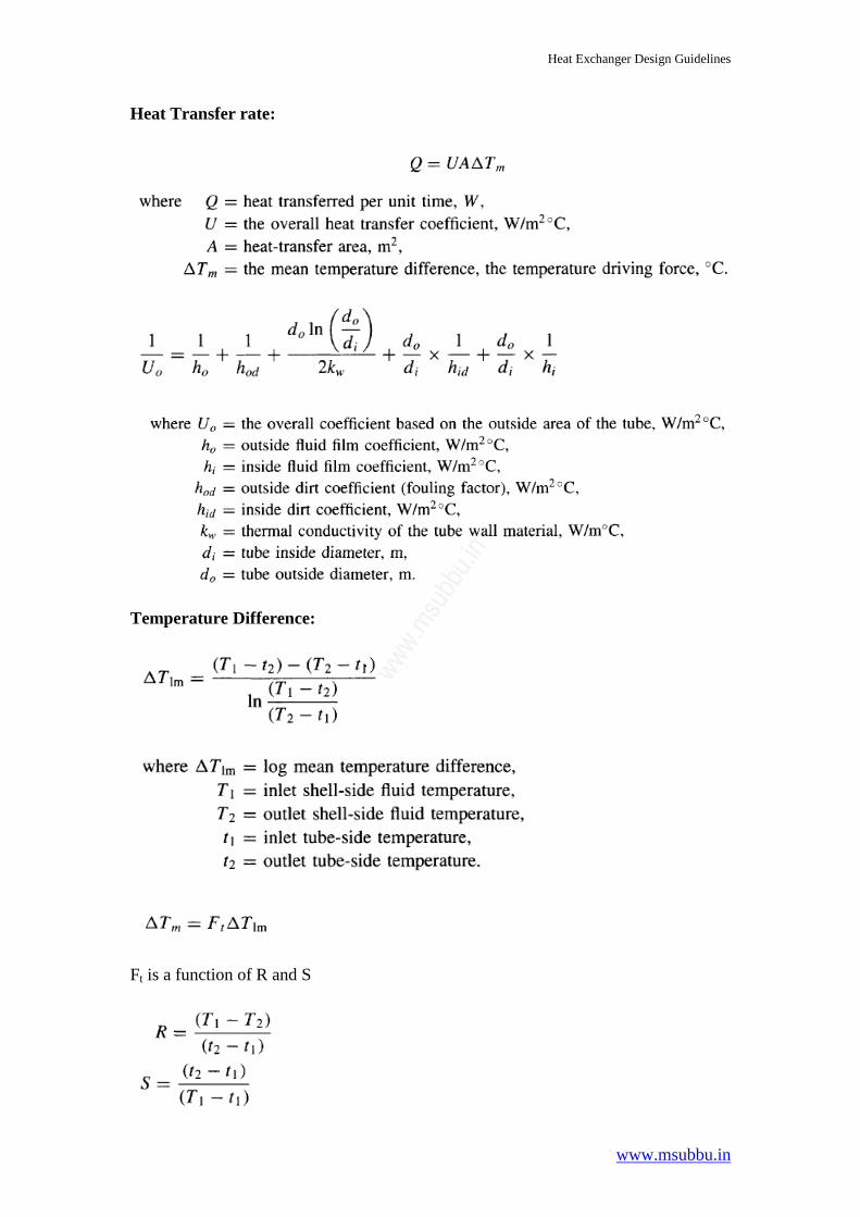
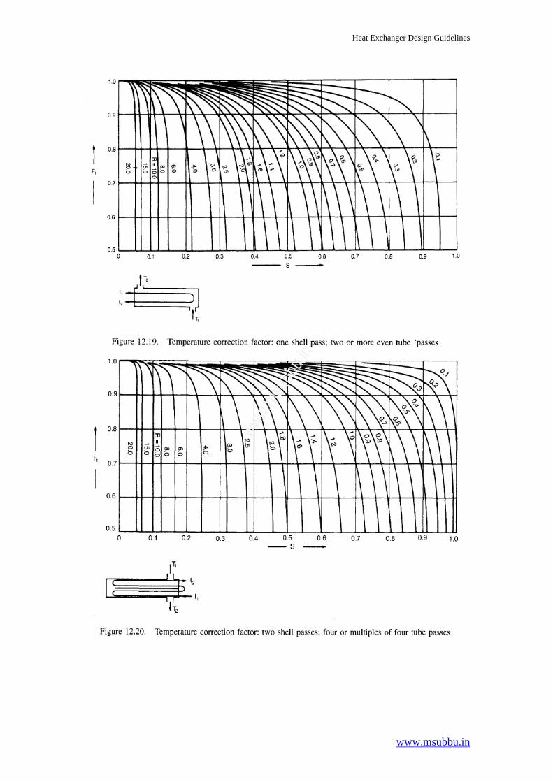
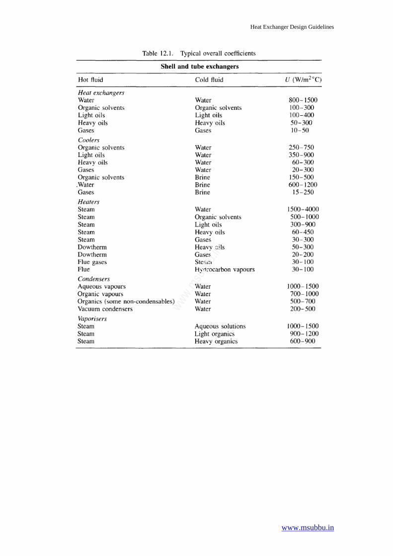
Heat Exchanger Design Guidelines
www.msubbu.in
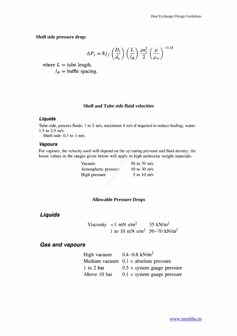
Shell side pressure drop:
Shell and Tube side fluid velocities
Allowable Pressure Drops
ww
w.m
subbu.in
Heat Exchanger Design Guidelines
www.msubbu.in
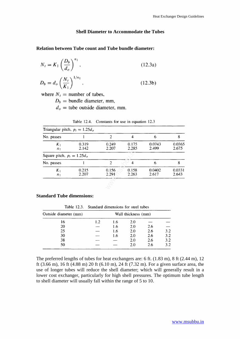
Shell Diameter to Accommodate the Tubes Relation between Tube count and Tube bundle diameter:
Standard Tube dimensions:
The preferred lengths of tubes for heat exchangers are: 6 ft. (1.83 m), 8 ft (2.44 m), 12 ft (3.66 m), 16 ft (4.88 m) 20 ft (6.10 m), 24 ft (7.32 m). For a given surface area, the use of longer tubes will reduce the shell diameter; which will generally result in a lower cost exchanger, particularly for high shell pressures. The optimum tube length to shell diameter will usually fall within the range of 5 to 10.