Abstract— Currently, distillation columns consume a large amount of energy in petroleum and alcohol industry. This has led to the development of a new internal configuration in the distillation columns called Heat-Integrated Distillation Column (HIDiC). In this configuration the column is composed for two concentric sections called rectifying and stripping. The heat transfer is conducted from the rectifying section (which works at higher pressure and temperature) to the stripping section (which works at lower pressure and temperature) forming a fractionating column. The HIDiC offers great potential to reduce energy consumption compared to the conventional column. However, the complexity of the proposed configuration justifies the need of rigorous simulations that enable a better understanding of the column operation. In this work, the computational fluid dynamic (CFD) was used to study the heat transfer in a concentric stage of a HIDiC column. The results obtained by CFD simulation showed the internal heat transfer as a promissory configuration for decrease energy consumption in distillation processes. Keywords: Computational Fluid Dynamics, Distillation, Heat Transfer, HIDiC, Temperature Distribution. I. INTRODUCTION A large percentage of energy in the chemical and petrochemical industries is consumed in the separation process. A new concept of the internal heat integration in distillation column, known in the literature as HIDiC, has a great setting potential for reducing energy consumption in the distillation processes. Basically the new configuration, unlike the conventional column, is where the separation occurs through the interaction between the vapor and liquid phase on plates located along the column. HIDiC reduces the energy load required by the condenser and re-boiler placing the rectifying section concentrically to the stripping section. The stream feeds enters into the first plate of the stripping section and the top product is transported to a compressor that increases the pressure and temperature of the steam to be fed at the bottom of the rectifying section. The heat from the rectifying section is used to the stripping section located concentrically. The top Manuscript received July 14, 2010. This work was supported in part by the São Paulo Research Foundation - FAPESP under Grant 2008/07572-1, Laboratory of Development Separation Processes - LDPS and Laboratory of Design Optimization and Advanced Control - LOPCA. J. L. Pulido was with University of Campinas, Sao Paulo, CEP 13083-852 - Campinas – Brasil; phone: (19) 3521 3909; fax: (19) 3521 3965; e-mail: [email protected]. product of the rectifying section is the distillate and the bottom of this section is fed back to the stripping column by means of a throttle valve. The new concept of heat-integrated distillation column HIDiC[1] by specifying a column based on the concept of conventional distillation. This configuration proposes the integration between the rectifying section and the stripping section, using the heat from the rectifying section to be transferred to the stripping section. Several studies done by Japanese research groups presented an analysis and parameters optimization for an ideal column HIDiC [2] through comparative studies with respect to the conventional column showing the energy savings potential presented by this configuration. In addition, studies presented a new concept for this setting in the Netherlands developed by the University of Delft [3], considering the internal heat integration as the key to reducing consumption energy in distillation columns. Later a study regarding the reduction of CO 2 emissions and energy consumption by using columns with internal heat integration was realized [4]. In recent years, many researches using computational fluid dynamic (CFD) techniques have been carried out in order to investigate the hydro/aerodynamic behavior and reveal the effects imposed by geometry of various internals in industrial columns. A comprehensible experimental and simulation study indicating that a state of art CFD tool is capable of predicting reliably the effect of column internals geometry on the single-phase gas flow [5]. However, there is still a long way ahead and many obstacles to overcome on the hardware and software side and to create computational capabilities to move from an empirical to a more fundamentally founded column design, which will culminate to the development of the method of scientific design. Furthermore, owning the complexity of the proposed HIDiC configuration, the need of simulations that enable a better understanding of the column operation is necessary. In this work, computational fluid dynamic (CFD) was used to study the heat transfer and fluid dynamic behavior in a plate of HIDiC in order to describe the functionality of column configuration. II. HEAT INTEGRATED DISTILLATON A. Concept of concentric column HIDiC Fig. 1 shows a diagram illustrating the distillation column with concentric heat integration, where heat transfer occurs Heat Transfer Study in a Concentric Stage of an Internally Heat-Integrated Distillation Column (HIDiC) Using CFD Simulation Jeffrey L. Pulido, Edgar L. Martinez, Aulus R. R. Bineli, Maria R. Wolf and Rubens M. Filho Proceedings of the World Congress on Engineering and Computer Science 2010 Vol II WCECS 2010, October 20-22, 2010, San Francisco, USA ISBN: 978-988-18210-0-3 ISSN: 2078-0958 (Print); ISSN: 2078-0966 (Online) WCECS 2010
Transcript
Abstract— Currently, distillation columns consume a large amount of energy in petroleum and alcohol industry. This has led to the development of a new internal configuration in the distillation columns called Heat-Integrated Distillation Column (HIDiC). In this configuration the column is composed for two concentric sections called rectifying and stripping. The heat transfer is conducted from the rectifying section (which works at higher pressure and temperature) to the stripping section (which works at lower pressure and temperature) forming a fractionating column. The HIDiC offers great potential to reduce energy consumption compared to the conventional column. However, the complexity of the proposed configuration justifies the need of rigorous simulations that enable a better understanding of the column operation. In this work, the computational fluid dynamic (CFD) was used to study the heat transfer in a concentric stage of a HIDiC column. The results obtained by CFD simulation showed the internal heat transfer as a promissory configuration for decrease energy consumption in distillation processes. Keywords: Computational Fluid Dynamics, Distillation, Heat Transfer, HIDiC, Temperature Distribution.
I. INTRODUCTION
A large percentage of energy in the chemical and petrochemical industries is consumed in the separation process. A new concept of the internal heat integration in distillation column, known in the literature as HIDiC, has a great setting potential for reducing energy consumption in the distillation processes. Basically the new configuration, unlike the conventional column, is where the separation occurs through the interaction between the vapor and liquid phase on plates located along the column. HIDiC reduces the energy load required by the condenser and re-boiler placing the rectifying section concentrically to the stripping section. The stream feeds enters into the first plate of the stripping section and the top product is transported to a compressor that increases the pressure and temperature of the steam to be fed at the bottom of the rectifying section. The heat from the rectifying section is used to the stripping section located concentrically. The top
Manuscript received July 14, 2010. This work was supported in part by the São Paulo Research Foundation - FAPESP under Grant 2008/07572-1, Laboratory of Development Separation Processes - LDPS and Laboratory of Design Optimization and Advanced Control - LOPCA.
J. L. Pulido was with University of Campinas, Sao Paulo, CEP 13083-852 - Campinas – Brasil; phone: (19) 3521 3909; fax: (19) 3521 3965; e-mail: [email protected].
product of the rectifying section is the distillate and the bottom of this section is fed back to the stripping column by means of a throttle valve.
The new concept of heat-integrated distillation column HIDiC[1] by specifying a column based on the concept of conventional distillation. This configuration proposes the integration between the rectifying section and the stripping section, using the heat from the rectifying section to be transferred to the stripping section. Several studies done by Japanese research groups presented an analysis and parameters optimization for an ideal column HIDiC [2] through comparative studies with respect to the conventional column showing the energy savings potential presented by this configuration. In addition, studies presented a new concept for this setting in the Netherlands developed by the University of Delft [3], considering the internal heat integration as the key to reducing consumption energy in distillation columns. Later a study regarding the reduction of CO2 emissions and energy consumption by using columns with internal heat integration was realized [4].
In recent years, many researches using computational fluid dynamic (CFD) techniques have been carried out in order to investigate the hydro/aerodynamic behavior and reveal the effects imposed by geometry of various internals in industrial columns. A comprehensible experimental and simulation study indicating that a state of art CFD tool is capable of predicting reliably the effect of column internals geometry on the single-phase gas flow [5]. However, there is still a long way ahead and many obstacles to overcome on the hardware and software side and to create computational capabilities to move from an empirical to a more fundamentally founded column design, which will culminate to the development of the method of scientific design.
Furthermore, owning the complexity of the proposed HIDiC configuration, the need of simulations that enable a better understanding of the column operation is necessary. In this work, computational fluid dynamic (CFD) was used to study the heat transfer and fluid dynamic behavior in a plate of HIDiC in order to describe the functionality of column configuration.
II. HEAT INTEGRATED DISTILLATON
A. Concept of concentric column HIDiC
Fig. 1 shows a diagram illustrating the distillation column with concentric heat integration, where heat transfer occurs
Heat Transfer Study in a Concentric Stage of an Internally Heat-Integrated Distillation Column
(HIDiC) Using CFD Simulation
Jeffrey L. Pulido, Edgar L. Martinez, Aulus R. R. Bineli, Maria R. Wolf and Rubens M. Filho
Proceedings of the World Congress on Engineering and Computer Science 2010 Vol II WCECS 2010, October 20-22, 2010, San Francisco, USA
from the rectifying section to the stripping section. To ensure conditions of operation a compressor and a valve are part of the system for operation.
Fig. 1 - Concentric heat transfer concept.
The concept of the HIDiC column used the heat transfer from the rectifying section to the stripping section causing the rectifying section to operate at higher pressure and temperature. The heat required to evaporate the liquid in the stripping section is obtained from the rectifying section, which decreases the energy charge in the re-boiler. Thus this new configuration ideally seeks to reduce the energy required by the condenser and the re-boiler to zero.
B. Hydraulic Design
The calculations developed for HIDiC column are based on a conventional column, taking into account external factors and associated heat transfer and pressure. Studies related to a design method for columns with internal integration and heat reflecting the configuration [6].
The hydraulic model shown in this work was developed in the Laboratory of Development for Separations Processes (LDPS) in Brazil based on the hydraulic diameter presented by Japanese researches [7], which reported an experimental study of the pilot plant operation of a column with heat internal integration. This model’s dimensions took into account factors of flooding and flow behavior in settings of high and low pressures for perforated plate modified according to the fluid dynamics of the column.
Heat transfer between sections were made using the heat content in the rectifying section to determine the heat transferred to the concentric column that operates as stripping section. This study does not include exchangers or panels that allow improving the heat transfer to the stripping section.
The heat transfer at the plate is calculated by solving the heat transfer equation in the solid domain and the momentum equation in the fluid domain. The numerical data such as fluid flow rates, pressure, and inlet temperatures were obtained based on the column simulation in ASPEN studies for the HIDiC column [8].
III. SECTION COLUMN HIDiC
The column section used for the study of heat transfer is shown in Fig. 2. The red region represents the rectifying section and the blue region represents the stripping section. ANSYS CFX 12.0® (of Ansys Inc., Europe) software was used for analysis, which allows three-dimensional analysis by specifying the configuration design of plate and column size scale.
The great advantage of using CFD simulation is the rigorous numerical analysis of design allowing the analysis of gas and liquid flow inside the column. One of the higher problems is the complexity of the internal configuration, requiring a detailed mesh able to capture fluid behavior, which increases the number of calculations.
A. Design and characterization of plate
This study proposed a perforated plate model, where the liquid flows are scattered on the plate and the inner section is a cylindrical down comer due to low liquid flow rate. The design of such dish is cheaper and easier compared to the bubble-cap. The perforated plate also has more capacity and introduced restrictions on low flows of steam. For the geometrical configuration of plate, concepts of distillation column design and data available in the literature for calculating diameter of holes and landfills, were used [9]. A distribution type 'square'
Rectifying section
Q
Stripping section
Heat transfer enforced
vaporization
Proceedings of the World Congress on Engineering and Computer Science 2010 Vol II WCECS 2010, October 20-22, 2010, San Francisco, USA
and 'triangle' was used for the rectifying and stripping section respectively, as shown in Fig. 3.
Fig. 3 - Internal design the perforated plate. Distribution type 'square' and 'triangles' for rectifying and stripping, respectively.
The book of Bhatia describes a process for the design of plates in the distillation columns [10], which takes into account vapor rates and estimates of liquid dish according to empirical correlations established for the calculation of the specifications of the plate. These concepts were also applied to the design of the perforated plate analyzed
IV. CFD MODEL DEVELOPMENT
Computational fluid dynamics simulation has been performed with the finite volume software code ANSYS CFX 12.0® (of Ansys Inc., Europe). This is a general purpose commercial CFD packed that solves the heat transfer and Navier-Stokes equations using finite volume method via coupled solver. This will provide comprehensive modeling to calculate the velocity and pressure field also concentration and temperature profiles.
As a result the model considered the gas phase (mixture of benzene and toluene) as one phase continuum having the same transport equations. The basic derivation of flow transport equations have been reported elsewhere and therefore will not be described in this work [11]. Furthermore, the mathematical forms of all transport equations can be found in the CFX Manual.
A. Domain description
The first important part of this work was the fluid dynamics study of the rectifying and stripping section in order to ascertain the influence of the flow non-uniformities (recirculation, back mixing, pooling zones, dead zones, etc.) on the hydraulic and performance of perforate plate. Subsequently this data was used to obtain the heat transfer through the perforated plate. The perforated plate was designed according to concepts necessary for the design of distillation columns [9].
The main details of the perforate plate design are given in the Table I and II.
For the rectifying and stripping domain, the well known standard k-ε turbulence model was applied to model the turbulence phenomena of the gas flow. In order to specify the detail geometry of the plate perforate refine mesh was applied around the perforations through CFX Mesh (the tool of making grids of CFX). The total number of unstructured elements within the computational domain (solid and fluid) of the rectifying and stripping sections was 3,749,948 respectively, as shown in the Fig. 4-6.
Fig. 4 – 3D Fluid domain (stripping and rectifying).
Table I – Plate specifications of the rectifying section
Geometry Dimension
Plate Diameter 0.45 m
Hole Diameter 0.028 m
Active area 80% of total area
Downcomer 10% of total area
Plate height 0.4 m
Fig. 5 – Fluid and solid domain.
The boundary conditions were used to create input required
by the Solver. The mesh file was loaded into the physics pre-processor, and the thermal properties of solid and fluid domain were implemented. The entrance mass flow rate and temperature for rectifying section were 1 kg/s and 385.4 K. For the stripping section, the entrance mass flow rate and temperature were 2 kg/s and 366.5 K. For both entrances a mass fraction of 0.11 and 0.89 for toluene and benzene, were
Proceedings of the World Congress on Engineering and Computer Science 2010 Vol II WCECS 2010, October 20-22, 2010, San Francisco, USA
respectively considered. The outlets were defined with constant relative pressure because the velocity in the output was unknown. The no slip condition at the surfaces were considered because the fluid velocity near the wall was affected by friction effects and the stripping external face was adiabatic.
Table II – Plate specifications of the stripping section
Geometry Dimension
Inside Diameter 0.80 m
Outside Diameter 0.47 m
Perforation Diameter 0.025 m
Active area 80% of total area
Downcomer 10 % of total area
Pate height 0.04 m
For the solid domain, that included the stripping and
rectifying columns, steel was assumed as material and a mesh with 916,500 elements (Fig. 6) to study the heat transfer.
Fig. 6 – 3D Solid domain (stripping and rectifying).
V. ANALYSIS AND RESULTS
By CFD simulation, the heat distribution in the column stage HIDiC could be obtained using the heat transfer by convection of the gas mixture flow in the rectifying and stripping sections. A concentric section consisting of two annular stages are designed to study the behavior of the heat generated by the fluid circulating in the two columns and operating conditions previously established.
The predicted temperatures profiles are shown in Fig. 7 – 11 and specifications obtained are shown below.
A. Rectifying section
As mentioned above, the rectifying section demonstrates heat transfer to the stripping section and means of convection heat transfer of the fluid flowing. In Fig. 7 the temperature decrease
of the mixture gas of 385 K in the plate center to 377 K at solid interface.
Fig. 7 – Temperature distribution in rectifying section
B. Stripping section
In the case of the stripping section, where the heat is obtained from the hotter rectification section, Figure 8 shows the temperature distribution in the perforate plate. From this simulation study, you can observed the radial decrease of the temperature of 375 K in the solid interface to 367 K at the wall column. In addition, a low temperature difference between rectifying and stripping section was observed, which it is preferred for HIDiC column according to paper presented by Sun et al. [12]. This leads to a large heat transfer area requirement for stage and the HIDiC design should allow for large a heat transfer area inside the column.
Fig. 8 – Temperature distribution in stripping section
Proceedings of the World Congress on Engineering and Computer Science 2010 Vol II WCECS 2010, October 20-22, 2010, San Francisco, USA
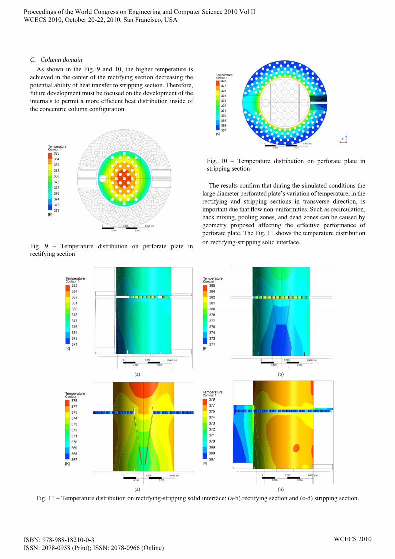
As shown in the Fig. 9 and 10, the higher temperature is achieved in the center of the rectifying section decreasing the potential ability of heat transfer to stripping section. Therefore, future development must be focused on the development of the internals to permit a more efficient heat distribution inside of the concentric column configuration.
Fig. 9 – Temperature distribution on perforate plate in rectifying section
Fig. 10 – Temperature distribution on perforate plate in stripping section
The results confirm that during the simulated conditions the
large diameter perforated plate’s variation of temperature, in the rectifying and stripping sections in transverse direction, is important due that flow non-uniformities. Such as recirculation, back mixing, pooling zones, and dead zones can be caused by geometry proposed affecting the effective performance of perforate plate. The Fig. 11 shows the temperature distribution
on rectifying-stripping solid interface.
(a) (b)
(a) (b)
Fig. 11 – Temperature distribution on rectifying-stripping solid interface: (a-b) rectifying section and (c-d) stripping section.
Proceedings of the World Congress on Engineering and Computer Science 2010 Vol II WCECS 2010, October 20-22, 2010, San Francisco, USA
The simulation studies using CDF software tool allow to observe the behavior of heat of the concentric section of HIDiC column. The operating conditions must be optimized for improved heat transfer from one section to another. This presents the need for arrangements within the column to improve heat transfer between sections.
Nowadays, with the changing market together with globalization trends, faster innovation cycles are necessary. Therefore, a more effective utilization of computational tools available may improve equipment manufacturing and develop of new processes to respond successfully to future distillation technology challenges.
A significant improvement in capacity of heat transfer could be achieved by implementation of internals in the concentric configuration in order to obtain a sufficiently large surface area for heat transfer. Certainly, further heat transfer improvement is possible and can optimized the plate column design for a better contact between the rectifying and stripping sections that will decrease energy consumption.
The results indicated that Computational Fluid Dynamics (CFD) is a tool capable of predicting reliably effects of column internals geometry on the multiphase flow field and can be considered as useful aid for design and evaluation of performance of the HIDiC column with or without internals. However, the disadvantage of this tool is related with immense run time associated for CFD simulations.
ACKNOWLEDGMENT
The authors acknowledge the financial support of FAPESP (Research Support Foundation of São Paulo) and support of laboratories LDPS (Laboratory of Development for Separation Process) and LOPCA (Laboratory of Optimization, Planning and Advanced Control).
REFERENCES
[1] NAKAIWA, M.; HUANG, K.; NAITO, K.; ENDO, A.; OWA, M.; AKIYA, M.; NAKANE, T.; TAKAMASU, T. A new configuration of ideal heat integrated distillation columns. Comput. Chem. Eng., v. 24, p. 239-245, 2000.
[2] NAKAIWA, M.; HUANG, K.; NAITO, K.; ENDO, A.; OWA, M.; AKIYA, M.; NAKANE, T.; TAKAMASU, T. Parameter analysis and optimization of ideal heat integrates distillation column. Comput. Chem. Eng., v. 25, p. 737-744, 2001.
[3] OLUJIC, Z.; FAKHRI, F.; RIJKE, A.; GRAAUW, J.;JANSENS, P.J. Internal heat integration – the key to an energy-conserving distillation column. J. Chem. Technol. Biotechnol., v. 78, p. 241-248, 2003.
[4] GADALLA, M.; OLUJIC, Z.; JANSENS, P. J.; JOBSON, M.; SMITH, R. Reducing CO2 emissions and energy consumption of heat-integrated distillation systems. Environ. Sci. Technol., v. 39, p. 6860-6870, 2005.
[5] ALI, M.A.; JANSENS, P.J.; OLUJIC, Z. Trans. IchemE, Part A: CERD., v. 81, p. 108, 2003.
[6] GADALLA, M.; OLUJIC, Z.; ESTELLER, L. J.; GONSÁLBEZ, G. A design method for internal heat integrated distillation columns (iHIDiCs). ESCAPE12. 2007.
[7] NAITO, K.; NAKAIWA; M.; HUANG, K.; ENDO, A.; ASO, K.; NAKANISHI, T.; NAKAMURA, T.; NODA, H.; TAKAMATSU, T. Operation of a bench-scale ideal heat integrated distillation column (HIDiC): an experimental study. Comput. Chem. Eng., v. 24, p. 495-499, 2000.
[8] PULIDO, J. L. Estudio de un nuevo concepto de columna de destilación: columna de destilación con integración interna de calor ´HIDiC`. Universidad Industrial de Santander. Tesis de grado ingeniero químico. 2008.
[9] WINKLE, M. V. Distillation. New York: McGraw-Hill, 1967.
[10] BHATIA, M. V. Transfer operations in process industries. Lancaster, Pennsylvania: TECHNOMIC Publishibg Co, 1983.
[11] RANADE, V. V. Computational Flow Modeling for Chemical Reactor Engineering, Academic Press, 2002.
[12] SUN, L.; de RIJKE, A.; OLUJIC, Z.; JANSENS, P.J. Process Innovation and Intensification Conference, Maastricht, The Netherlands, 2003.
Proceedings of the World Congress on Engineering and Computer Science 2010 Vol II WCECS 2010, October 20-22, 2010, San Francisco, USA