Heat Transfer to Separation Flow in Heat Exchangers
S. N. Kazi, Hussein Togun and E. Sadeghinezhad
Additional information is available at the end of the chapter
http://dx.doi.org/10.5772/51331
1. Introduction Separation flow is appeared over and behind a body surface when it is separated from that surface. In separation flow the region is relatively small compared to the body and enclosed by the separating stream line and points of separation and reattachment. Separation flows are formed at the upstream of a forward facing step downstream of a rearward facing step, within a cutout in a body surface and also on the upper surface of an airfoil.
The step separated flow is one of wedge-type separated flows, cutout flow (cavity-type separated flows) and the separated region over an airfoil (separation bubbles). A relatively small incidence angle between the separated flow and the body at points of separation and reattachment represents the wedge-type separated flow. On the other hand in cavity type separated flow the body boundaries at separation and reattachment are in general approximately perpendicular to the flow direction. An abrupt change of geometrical configuration of the body surface causes these two types of flow separation. The separation flow is strongly dependent on the nature of flow, such as laminar, transitional or turbulent.
In practice the separated flows are caused by flaps for deflection, spoiler control, rocket nozzle of over expanded type, leeward side of an object inclined at a large angle of attack etc. In practical cases the vortices of separated flow are unsteady and it is difficult to experimentally study. In a cutout the simulation of practical situation is considered and the understanding of the mechanics of real vortices and noise caused could be achieved. The present study highlights the separation flow mechanism, heat transfer to separated flow with subsequent pressure loss and possible use in practice.
2. Control of separation flow Separation flow is performed to ratio the efficiency or to improve the performance of equipment, vehicles and machineries involving many engineering applications. The
An Overview of Heat Transfer Phenomena 498
separation of flow may be controlled in two ways, such as (i) by prevention or delay of the onset of separation regions and (ii) with the help of provoking localized separation flow by utilizing the separated flow characteristics.
3. Prevention of delay of separation of flow
Adverse pressure gradient and viscosity are the two governing factors of flow separation. By changing or maintaining the structure of viscosity flow the control of separation can be achieved. Pressure gradient and viscosity ultimately prevent or delay the separation. Further, by designing the geometrical configuration the separation flow may be controlled, such as a pump could be used to suck the boundary layer flow away for suppressing the flow.
4. Retardation of the delay of separation by geometrical design of the body surface
Geometrical configurations include the basic body surface configuration, slot, vortex generator, notch, heating edge extension, step passage etc. These arrangements are adequately installed with respect to the body configurations.
Methods of computation for potential pressure distribution, boundary layer development, separation criteria etc. should be well understood for obtaining the controlled separation by basic body design from analysis. These analytical predictions on body configurations are not regular accessable, so additional geometrical shaping are employed if the design of the basic body geometry is not adequate to control the separation.
5. Reduction of heat transfer in separation region and delay of separation by cooling
Reduction of heat transfer in separation flow of laminar flow phenomena is obtained by injecting gas into that region. This technique may be practically applied in special case. Charwat and Dewey [1] computed the recovery factor in separation flow as a function of mass injection. They presented recovery factor as a function of dimensionless mass flow injection where, parameter Pr=1, 0.72 and 0.55 represents width of two-dimensional flow, l the length of separated mixing layer, c is constant of proportionally between viscosity and temperature. ζRepresents dimensionless mass-flow variable defined by equation (1).
ζ = Ψ∗/ X∗ (1) Ψ∗ is a transformed stream function
Ψ∗ = Ψ/ υ u lc (2)
ρu = ρ (3)
Heat Transfer to Separation Flow in Heat Exchangers 499
ρv = −ρ (4)
Where,
L is length of separated mixing layer, c is constant of proportionality between viscosity and temperature. ∗=X/L. X is coordinate parallel to direction of flow along the dividing stream line (Ψ = 0) within the mixing layer, mi is the injected mass flux which is equal to density x velocity x area
The recovery factor is expressed as (5),
q = (h -h )/(u /2) (5)
Where,
Haw is enthalpy per unit mass at adiabatic wall conditions.
At Pr=1, the recovery factor is independent of mass injection. When Pr<1, the recovery factor drops with injection or mixing in boundary layer. The dotted line represent the computed value at r as obtained by low [2].
The pressure gradient deepens and the extent of the separated region is delayed and vice versa when the wall of the body is cooled. Illingworth [3] observed that the separation distance of laminar has flow reduced by 16 percent by raising the wall temperature from that of room to the boiling point for a retarding laminar flow.
Recirculation flows with separation generates high pressure losses accompanied by enhancement of turbulence and argumentation of heat and mass transfer rate.
6. Thermal effects on separation flow
At subsonic speed, the heat transfer of separation flows is given emphasis due to the existing design of heat transfer equipment. Attention is drawn by the phenomena of separation flow which holds existence of a hot spot in reattachment region. With laminar and turbulent flow, specially in laminar flow separation have become concern.
6.1. Heat transfer in separation flow
The heat transfer of separated flows at subsonic speeds is important for the design of heat transfer equipment. In flow separation, turbulence augments heat transfer in general but in particular region due to flow reattachment heat transfers and hot spot develops. Investigators are attracted to the point of reattachment. Flow separation, mainly laminar flow and its analytical study has become a concern. The onset of separation flow and its characteristics have not been understood yet. From the analysis, some knowledge has been gathered. Gadd [4] has presented heat transfer effects in separation air flow on the relevant pressure gradient extended to the separated region.
An Overview of Heat Transfer Phenomena 500
6.1.1. Heat transfer in the separated flow through sudden expansion
a. Experimental studies (Turbulent range)
There are many researchers, who investigated experimental study of turbulent heat transfer in separation flow with different geometries such as separation flow for sudden expansion in passage, backward or forward facing step, blunt body, rib channels, and swirl generators. The summary of references has been selected from the earliest studies to recent studies and included more detail about turbulent heat transfer in separation flow.
Sudden expansion
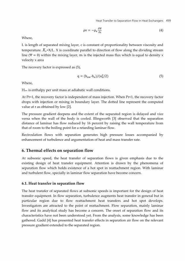
Boelter et al. [5] presented results of investigations conducted to observe the distributions of the heat transfer rate of air flowing in a circular pipe in the separated and reattached regions downstream of an orifice. The investigation was performed in Re range of 17,000 to 26,400 for internal pipe flow. They used various entrance sections as shown in Figure 1 which makes variation of point of reattachment at entrance pipe. From the experimental data obtained, they found maximum heat transfer coefficient near the point of reattachment which is about four times away of the length of fully developed flow.
Figure 1. Circular pipes with various entrance sections.
Heat Transfer to Separation Flow in Heat Exchangers 501
Ede et al. [6] have investigated the effect of an abrupt convergence of straight pipe on the local heat-transfer coefficient for flowing water. The experimental covered for Reynolds numbers from 800 to 100,000 corresponding to a smaller pipe of diameter 1 inch. They have also determined effect of an abrupt divergence at Reynolds numbers from 3,700 to 45,000 and observed a considerable variation in local heat transfer coefficient. Koram and Sparrow [7] had performed experimental study of turbulent heat transfer of water flowing in circular pipe with unsymmetric blockage (segmental orifice plate) for range of Reynolds number from 10,000 to 60,000.
Krall and Sparrow [8] conducted experiments to determine the effect of flow separation on the heat transfer characteristics of a turbulent pipe flow. The water flow separation was driven by an orifice situated at the inlet of an electrically heated circular tube. The degree of flow separation was varied by employing orifices of various bore diameters. The Reynolds and Prandtl numbers were varied from 1000 to 130000 and from 3 to 6 respectively and ratios of the orifice to the tube diameter ranged from 2/3 to 1/4. Results show that the augment of the heat transfer coefficient due to flow separation accentuated with the decrease of Reynolds number decreases as shown in Figure 2. They have also found the effect of expansion ratio on the distribution temperature. The point of flow reattachment, corresponding to maximum value of the heat transfer coefficient was found to occur from 1.25 to 2.5 pipe diameter from the onset of flow separation. Suzuki et al. [9] performed experiment to study heat transfer and visulation of flow and surface temperature in the recirculating flow of an orifice in tube where they obtained results similar to Krall and Sparrow [8].
Figure 2. Local Nusselt number distribution
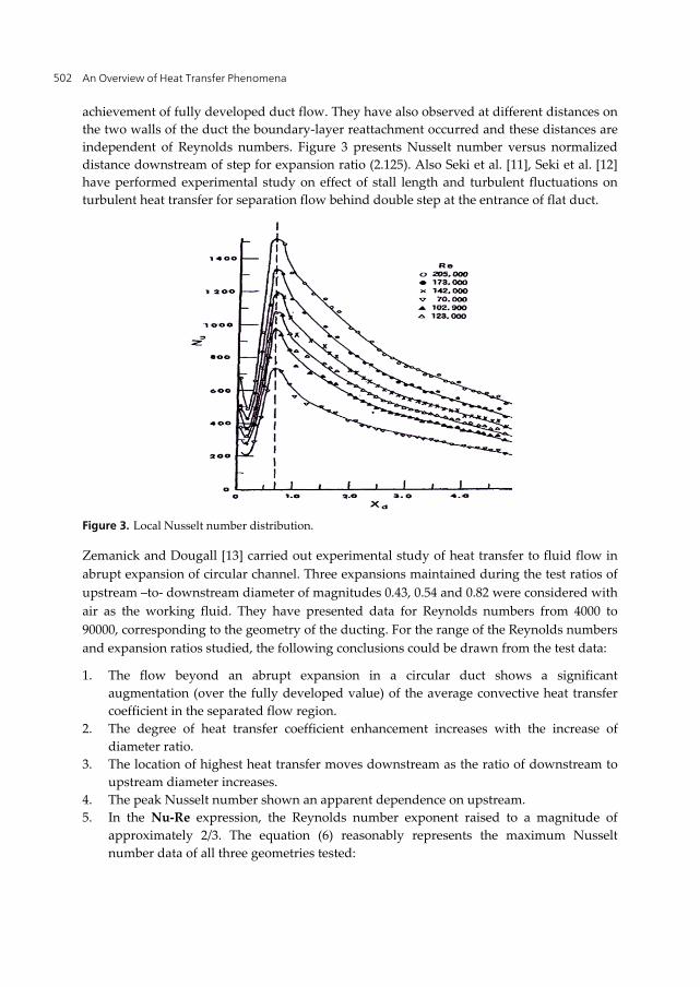
Filetti and Kays [10] presented experimental study on separation flow and heat transfer through flat duct with double step. They showed the highest heat transfer occurs in both long and short stall on sides at the point of reattachment, followed by decay towards the
An Overview of Heat Transfer Phenomena 502
achievement of fully developed duct flow. They have also observed at different distances on the two walls of the duct the boundary-layer reattachment occurred and these distances are independent of Reynolds numbers. Figure 3 presents Nusselt number versus normalized distance downstream of step for expansion ratio (2.125). Also Seki et al. [11], Seki et al. [12] have performed experimental study on effect of stall length and turbulent fluctuations on turbulent heat transfer for separation flow behind double step at the entrance of flat duct.
Figure 3. Local Nusselt number distribution.
Zemanick and Dougall [13] carried out experimental study of heat transfer to fluid flow in abrupt expansion of circular channel. Three expansions maintained during the test ratios of upstream –to- downstream diameter of magnitudes 0.43, 0.54 and 0.82 were considered with air as the working fluid. They have presented data for Reynolds numbers from 4000 to 90000, corresponding to the geometry of the ducting. For the range of the Reynolds numbers and expansion ratios studied, the following conclusions could be drawn from the test data:
1. The flow beyond an abrupt expansion in a circular duct shows a significant augmentation (over the fully developed value) of the average convective heat transfer coefficient in the separated flow region.
2. The degree of heat transfer coefficient enhancement increases with the increase of diameter ratio.
3. The location of highest heat transfer moves downstream as the ratio of downstream to upstream diameter increases.
4. The peak Nusselt number shown an apparent dependence on upstream. 5. In the Nu-Re expression, the Reynolds number exponent raised to a magnitude of
approximately 2/3. The equation (6) reasonably represents the maximum Nusselt number data of all three geometries tested:
Heat Transfer to Separation Flow in Heat Exchangers 503
Nu = 0.20Re . (6)
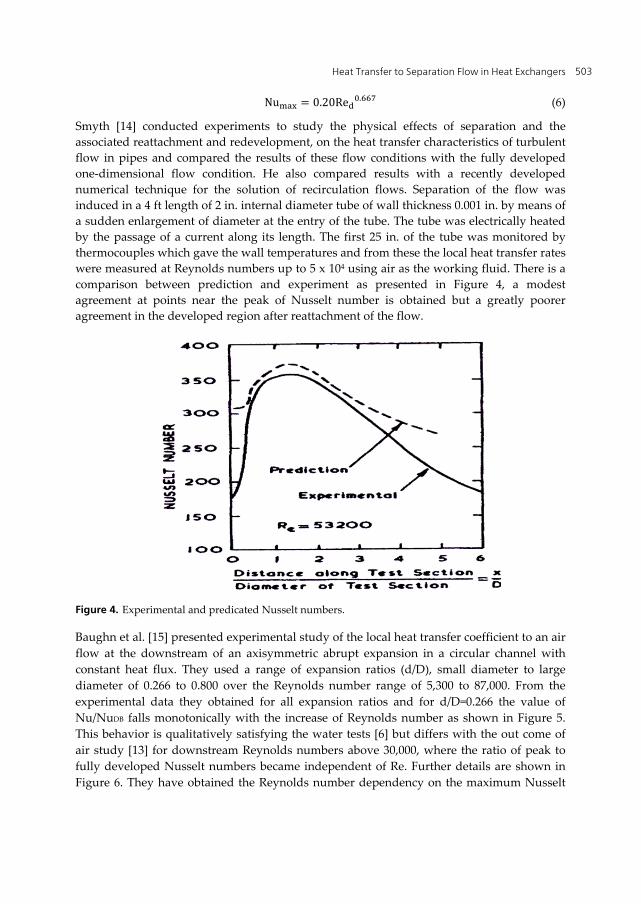
Smyth [14] conducted experiments to study the physical effects of separation and the associated reattachment and redevelopment, on the heat transfer characteristics of turbulent flow in pipes and compared the results of these flow conditions with the fully developed one-dimensional flow condition. He also compared results with a recently developed numerical technique for the solution of recirculation flows. Separation of the flow was induced in a 4 ft length of 2 in. internal diameter tube of wall thickness 0.001 in. by means of a sudden enlargement of diameter at the entry of the tube. The tube was electrically heated by the passage of a current along its length. The first 25 in. of the tube was monitored by thermocouples which gave the wall temperatures and from these the local heat transfer rates were measured at Reynolds numbers up to 5 x 10⁴ using air as the working fluid. There is a comparison between prediction and experiment as presented in Figure 4, a modest agreement at points near the peak of Nusselt number is obtained but a greatly poorer agreement in the developed region after reattachment of the flow.
Figure 4. Experimental and predicated Nusselt numbers.
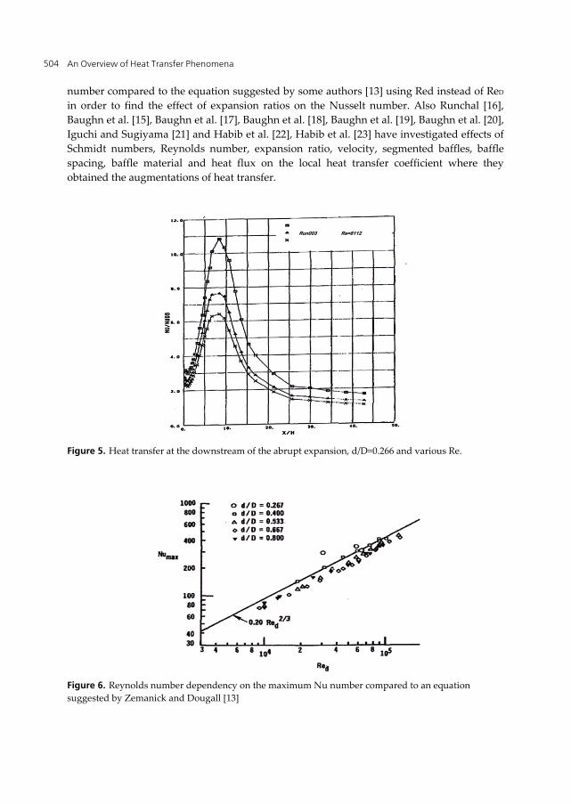
Baughn et al. [15] presented experimental study of the local heat transfer coefficient to an air flow at the downstream of an axisymmetric abrupt expansion in a circular channel with constant heat flux. They used a range of expansion ratios (d/D), small diameter to large diameter of 0.266 to 0.800 over the Reynolds number range of 5,300 to 87,000. From the experimental data they obtained for all expansion ratios and for d/D=0.266 the value of Nu/NuDB falls monotonically with the increase of Reynolds number as shown in Figure 5. This behavior is qualitatively satisfying the water tests [6] but differs with the out come of air study [13] for downstream Reynolds numbers above 30,000, where the ratio of peak to fully developed Nusselt numbers became independent of Re. Further details are shown in Figure 6. They have obtained the Reynolds number dependency on the maximum Nusselt
An Overview of Heat Transfer Phenomena 504
number compared to the equation suggested by some authors [13] using Red instead of ReD in order to find the effect of expansion ratios on the Nusselt number. Also Runchal [16], Baughn et al. [15], Baughn et al. [17], Baughn et al. [18], Baughn et al. [19], Baughn et al. [20], Iguchi and Sugiyama [21] and Habib et al. [22], Habib et al. [23] have investigated effects of Schmidt numbers, Reynolds number, expansion ratio, velocity, segmented baffles, baffle spacing, baffle material and heat flux on the local heat transfer coefficient where they obtained the augmentations of heat transfer.
Figure 5. Heat transfer at the downstream of the abrupt expansion, d/D=0.266 and various Re.
Figure 6. Reynolds number dependency on the maximum Nu number compared to an equation suggested by Zemanick and Dougall [13]
Run003 Re=8112
Heat Transfer to Separation Flow in Heat Exchangers 505
Hussein et al. (24) carried out experimental study of turbulent heat transfer and separated flow in an annular passage. They found the effect of separation flow on the average and local convective heat transfer and observed augmentation of local heat transfer coefficient occurred with the increase of heat flux and or Re while step height effect was clear at separation region and obtained increase in the local heat transfer coefficient with increase of step height.
b. Numerical studies (Turbulent range)
In the present chapter emphasis is given on the references which used various numerical methods to analyze turbulent heat transfer in separation flow for sudden expansion in passage, backward or forward facing step, blunt body, rib channels, and swirl generators.
Sudden expansion
Various models have been adopted to conduct heat transfer analysis in separated flow with sudden expansion. Chieng and Launder [24] performed numerical study of turbulent heat transfer and flow in separation region with an abrupt pipe expansion by using standard k-ε model and they obtained a good agreement with experimental data of Zemanick and Dougall [13].
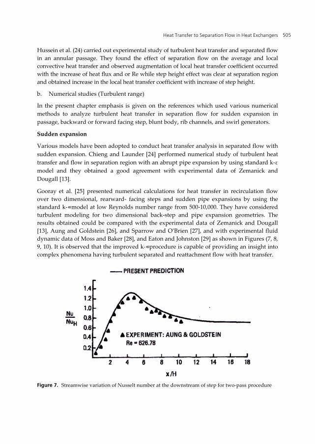
Gooray et al. [25] presented numerical calculations for heat transfer in recirculation flow over two dimensional, rearward- facing steps and sudden pipe expansions by using the standard k-∈ model at low Reynolds number range from 500-10,000. They have considered turbulent modeling for two dimensional back-step and pipe expansion geometries. The results obtained could be compared with the experimental data of Zemanick and Dougall [13], Aung and Goldstein [26], and Sparrow and O’Brien [27], and with experimental fluid dynamic data of Moss and Baker [28], and Eaton and Johnston [29] as shown in Figures (7, 8, 9, 10). It is observed that the improved k-∈ procedure is capable of providing an insight into complex phenomena having turbulent separated and reattachment flow with heat transfer.
Figure 7. Streamwise variation of Nusselt number at the downstream of step for two-pass procedure
An Overview of Heat Transfer Phenomena 506
Figure 8. Streamwise variation of Nusselt number at the downstream of sudden expansion for two-pass procedure.
Figure 9. Cross-stream variation of Nusselt number on the downstream face of the pipe expansion.
Heat Transfer to Separation Flow in Heat Exchangers 507
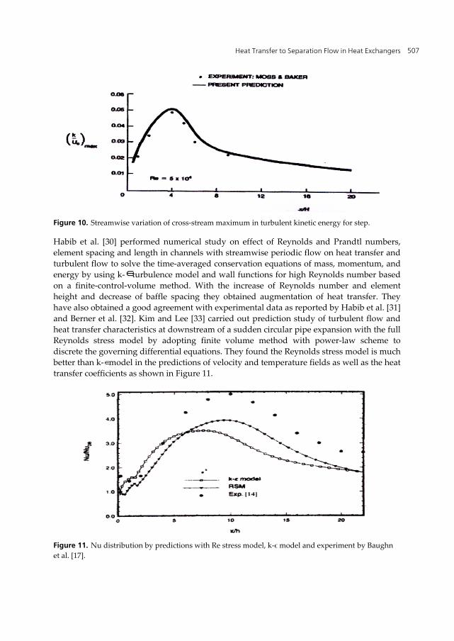
Figure 10. Streamwise variation of cross-stream maximum in turbulent kinetic energy for step.
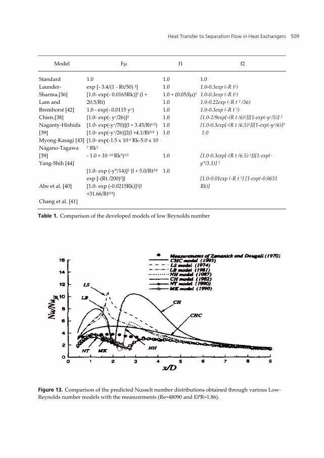
Habib et al. [30] performed numerical study on effect of Reynolds and Prandtl numbers, element spacing and length in channels with streamwise periodic flow on heat transfer and turbulent flow to solve the time-averaged conservation equations of mass, momentum, and energy by using k-∈ turbulence model and wall functions for high Reynolds number based on a finite-control-volume method. With the increase of Reynolds number and element height and decrease of baffle spacing they obtained augmentation of heat transfer. They have also obtained a good agreement with experimental data as reported by Habib et al. [31] and Berner et al. [32]. Kim and Lee [33] carried out prediction study of turbulent flow and heat transfer characteristics at downstream of a sudden circular pipe expansion with the full Reynolds stress model by adopting finite volume method with power-law scheme to discrete the governing differential equations. They found the Reynolds stress model is much better than k-∈ model in the predictions of velocity and temperature fields as well as the heat transfer coefficients as shown in Figure 11.
Figure 11. Nu distribution by predictions with Re stress model, k-ϵ model and experiment by Baughn et al. [17].
An Overview of Heat Transfer Phenomena 508
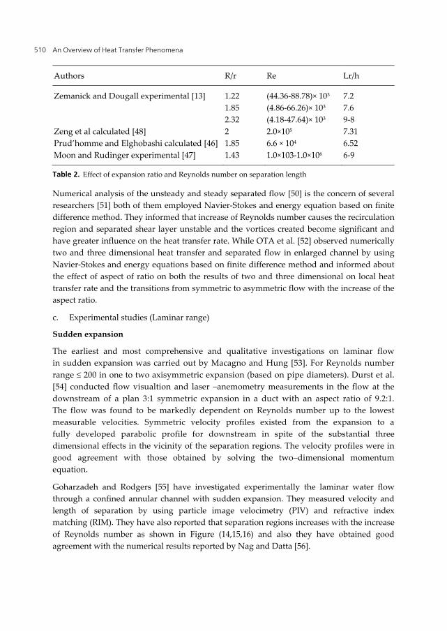
Chung and Jia [34] studied numerically turbulent heat transfer in abrupt expansion by using new K-∈ model and they found enhanced turbulent kinetic energy and velocity and noticed a good agreement with previous experimental data. Hsieh and Chang [35] observed numerically the wall heat transfer in pipe expansion turbulent flows by applying a new modified low-Reynolds number k-∈ turbulence [Chang, Hsieh and Chen (CHC)] model and compared the performance of nine other conventional low-Reynolds number k-∈ models developed earlier by Launder and Sharma [36], Lam and Bremhorst [37], Chien [38], Nagano and Hishida [39], Myong and Kasagi [41], Nagano and Tagawa [42], Yang and Shih [43], Abe et al. [40], and Chang et al. [41] (Table 1) provided a summary of model functions. From comparisons of the predicted distributions of the Nusselt number obtained through the low- Reynolds number k-∈ models with data of Baughn et al. [17] (Figure 12) and Zemanick and Dougall [13] (Figure 13) they found only CHC model generates correct trend.
Guo et al. [45] performed numerical study of thermal effect in the recirculation zone due to sudden expansion for gas flow and they have the result compared with some experimental data to check the heating effect on the corner recirculation zone (CRZ) (Table 2) [13, 46, 47]. Experimental and numerical data are showing Reynolds number and the expansion ratio on the CRZ for the sudden expansion turbulent flows.
Sugawara et al. [49] analyzed numerically the large eddy simulation (LES) method. They have studied the three dimensional turbulent heat transfer and separated flow in a symmetric expansion plane channel by applying LES. They used smagorinsky model and fundamental equations based on finite difference method and found a good agreement between numerical data with previously published experimental data.
Figure 12. Comparison of the predicted Nusselt number distributions obtained through various Low-Reynolds number models with the measurements (Re=17300 and EPR= 2.5).
Heat Transfer to Separation Flow in Heat Exchangers 509
Model Fμ f1 f2
Standard Launder-Sharma.[36] Lam and Bremhorst [42] Chien.[38] Naganty-Hishida [39] Myong-Kasagi [43]Nagano-Tagawa [39] Yang-Shih [44] Abe et al. [40] Chang et al. [41]
1.0 1.0-0.3exp (-R t2) 1.0-0.3exp (-R t2) 1.0-0.22exp (-R t 2 /36) 1.0-0.3exp (-R t 2) {1.0-2/9exp[-(R t /6)2]}[1-exp(-y+/5)] 2 {1.0-0.3exp[-(R t /6.5)2]}[1-exp(-y+/6)]2 1.0 {1.0-0.3exp[-(R t /6.5) 2]}[1-exp(-y*/3.1)] 2 [1.0-0.01exp (-R t 2] [1-exp(-0.0631 Rk)]
Table 1. Comparison of the developed models of low Reynolds number
Figure 13. Comparison of the predicted Nusselt number distributions obtained through various Low- Reynolds number models with the measurements (Re=48090 and EPR=1.86).
An Overview of Heat Transfer Phenomena 510
Authors R/r Re Lr/h
Zemanick and Dougall experimental [13] Zeng et al calculated [48] Prud’homme and Elghobashi calculated [46] Moon and Rudinger experimental [47]
Table 2. Effect of expansion ratio and Reynolds number on separation length
Numerical analysis of the unsteady and steady separated flow [50] is the concern of several researchers [51] both of them employed Navier-Stokes and energy equation based on finite difference method. They informed that increase of Reynolds number causes the recirculation region and separated shear layer unstable and the vortices created become significant and have greater influence on the heat transfer rate. While OTA et al. [52] observed numerically two and three dimensional heat transfer and separated flow in enlarged channel by using Navier-Stokes and energy equations based on finite difference method and informed about the effect of aspect of ratio on both the results of two and three dimensional on local heat transfer rate and the transitions from symmetric to asymmetric flow with the increase of the aspect ratio.
c. Experimental studies (Laminar range)
Sudden expansion
The earliest and most comprehensive and qualitative investigations on laminar flow in sudden expansion was carried out by Macagno and Hung [53]. For Reynolds number range ≤ 200 in one to two axisymmetric expansion (based on pipe diameters). Durst et al. [54] conducted flow visualtion and laser –anemometry measurements in the flow at the downstream of a plan 3:1 symmetric expansion in a duct with an aspect ratio of 9.2:1. The flow was found to be markedly dependent on Reynolds number up to the lowest measurable velocities. Symmetric velocity profiles existed from the expansion to a fully developed parabolic profile for downstream in spite of the substantial three dimensional effects in the vicinity of the separation regions. The velocity profiles were in good agreement with those obtained by solving the two–dimensional momentum equation.
Goharzadeh and Rodgers [55] have investigated experimentally the laminar water flow through a confined annular channel with sudden expansion. They measured velocity and length of separation by using particle image velocimetry (PIV) and refractive index matching (RIM). They have also reported that separation regions increases with the increase of Reynolds number as shown in Figure (14,15,16) and also they have obtained good agreement with the numerical results reported by Nag and Datta [56].
Heat Transfer to Separation Flow in Heat Exchangers 511
Figure 14. Measurements of velocity flow field at Re= 100
Figure 15. Measurements of velocity flow field at Re= 300
Figure 16. Measurements of velocity flow field at Re= 500
An Overview of Heat Transfer Phenomena 512
d. Numerical study (Laminar range)
Sudden expansion
Chiang et al. [57] have studied the effect of side wall on the laminar incompressible fluid flow over a plane symmetric sudden expansion. In their analysis, 14 aspect ratios were considered from 3 to 48, and Re=60 for three dimensional analysis and Re=60 and 140 for two dimensional analysis. The numerical results have given a good agreement with experimental results conducted by Fearn et al. [58] for symmetric flow at Re=26 and asymmetric flow at Re up to 36.
Boughamoura et al. [59] presented numerical date of heat transfer and laminar flow in a piston driven in a cylinder with sudden expansion by using finite element method with simpler algorithm of pressure –velocity coupling, and staggered and moved grid. The numerical results showed a good agreement with pervious experimental data where they observed the increase of expansion ratio leads to decrease the recirculating zone of the step plane. They have noticed also there are three regions created by moving the piston with sudden expansion namely primary vortex, secondary positive vortex, and secondary negative vortex. Pinho et al. [60] have numerically evaluated the pressure losses of laminar non Newtonian flow in sudden expansion having diameter ratio of 1 to 2.6. They used power law model to find irreversible pressure losses coefficient by equation 7.
12 21 1
1 12 2
I R FP P P PC
U U
(7)
The numerical results revealed the decrease of separation length with shear thinning and they also showed the variation of separation length is linear at high Reynolds number and become asymptote to constant value for creeping flow condition.
Thiruvengadam et al. [61] investigated three-dimensional mixed convection in vertical duct with sudden expansion. The effects of aspect ratio, heat flux, and buoyancy force on the laminar flow in separated regions were presented in their studies. They obtained sharp increase in the recirculation regions with the increase of aspect ratio as shown in Figure 17. Linear increasing of streamwise distribution and independent aspect ratio after recirculation region as shown in Figure 18.
6.1.2. Heat transfer in the separated flow over backward and forward step
a. Experimental studies (Turbulent range)
Forward and backward facing step
Seban et al. [62] studied experimentally heat transfer in the separated, reattached, and redeveloping flow regions around the downward facing step. They found that the heat
Heat Transfer to Separation Flow in Heat Exchangers 513
Figure 17. Distribution of local Nusselt number with aspect ratio
Figure 18. Distribution of streamwise of the average Nusselt number with aspect ratio
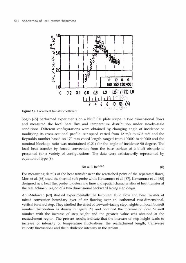
transfer coefficient reached a highest value at the reattachment point, and after that decreases as shown in Figure 19. Seban [63] investigated experimentally the relative effect of the suction and injection on the heat transfer and fluid flow in a separated region at downstream of a backward facing step for fixed rates of suction and injection through a slot at the base of the step, with air velocities in the free stream varied in the range of 15 to 45 m/s. They found that with the fixed suction the length of the separated region decreases as the free–stream velocity is reduced and the maximum value of the group (h/k) (υ/Ua)0.8 is also increased. With injection, there is no region of separated flow at the wall when the free–stream velocity is of the same order of the injection velocity and the local heat transfer is at first influenced primarily by the injection velocity [64].
An Overview of Heat Transfer Phenomena 514
Figure 19. Local heat transfer coefficient.
Sogin [65] performed experiments on a bluff flat plate stripe in two dimensional flows and measured the local heat flux and temperature distribution under steady–state conditions. Different configurations were obtained by changing angle of incidence or modifying its cross–sectional profile. Air speed varied from 12 m/s to 47.5 m/s and the Reynolds number based on 170 mm chord length ranged from 100000 to 440000 and the nominal blockage ratio was maintained (0.21) for the angle of incidence 90 degree. The local heat transfer by forced convection from the base surface of a bluff obstacle is presented for a variety of configurations. The data were satisfactorily represented by equation of type (8).
Nu = C. Re . (8)
For measuring details of the heat transfer near the reattached point of the separated flows, Mori et al. [66] used the thermal tuft probe while Kawamura et al. [67], Kawamura et al. [68] designed new heat flux probe to determine time and spatial characteristics of heat transfer at the reattachment region of a two dimensional backward facing step deign.
Abu-Mulaweh [69] studied experimentally the turbulent fluid flow and heat transfer of mixed convection boundary-layer of air flowing over an isothermal two-dimensional, vertical forward step. They studied the effect of forward–facing step heights on local Nusselt number distribution as shown in Figure 20, and obtained the increase of local Nusselt number with the increase of step height and the greatest value was obtained at the reattachment region. The present results indicate that the increase of step height leads to increase of intensity of temperature fluctuations, the reattachment length, transverse velocity fluctuations and the turbulence intensity in the stream.
Heat Transfer to Separation Flow in Heat Exchangers 515
Figure 20. Local Nusselt number variation at the downstream of the step.
Sano et al. [70] presented experimental results of the turbulent channel flow over a backward-facing step by using suction through a slit at the bottom corner of the step and the direction of the suction was perpendicular and horizontal to the main flow. They measured local heat transfer coefficient and wall static pressure behind the backward-facing step and obtained the enhancement of the heat transfer coefficient in the recirculating region with the increase of suction flow and reduction of the pressure drop.
b. Numerical studies (Turbulent range)
Forward and backward facing step
Shisnov et al. [71] studied the heat transfer in the recirculating region formed by a backward-facing step. They used a vertical structure of a recirculating flow formed by a backward-facing step with the comparable predicted separation zone lengths from the experimental data obtained by Etheridge and Kemp [72], Moss et al. [73], Kim et al. [75] Abbott and Kline [74], Tani et al. [75], Eaton and Johnston [76], Smyth [77], Seban [78], and Filetti and Kays [10] (see Table 3).
Abe et al. [40] performed studies to the predict heat transfer and fluid flow in separation and reattachment over backward facing step and suggested a new two equation heat transfer model obtained from the model of Youssef et al. [79]. Thus they presented a new model of low Reynolds number by using Kolmogorov velocity scale uε = (vε)1/4 instead of the friction velocity uT, which could predict heat transfer and fluid flow at downstream of backward facing step. While Heyerichs and Pollard [80] used mathematical model with the aid of the k-∈ and k-w turbulence models to study heat transfer with both separated and impinging turbulent flow. They showed that the K-w model is more simple numerical method to estimate heat transfer in complex turbulent flows. All models have predicted reasonable results for the channel flow test case and have shown a strong agreement with the log law and temperature data of Kader [81]. This result can be anticipated since they
An Overview of Heat Transfer Phenomena 516
are derived on the basis of the log-law and temperature log-law [82]. All low Reynolds number models except LB have predicted Cf within 5% error. When low Reynolds number approach is considering them a strong correlation between a models ability to predict the log-law, Cf and Nu. The models of LB [42] and MK Myong and Kasagi [43] underpredict the log law, overestimate Cf and Nu is obtained. The models of CH [38], and LS [39] overestimate the log-law, under predict Cf and Nu. The WCP(W) Wolfshtein [83] and (CH) Chein et al. [38] models show the best fit to the log-law and Nu as predicted within 1% error of the output from Dittus-Boelter correlation. When the low Reynolds number approach is used a strong correlation is obtained between the models ability to predict the log-law, Cf and Nu.
Reference Experimental xR
Predicated xR
Percentage error(%)
Shishov et al. [71] 6.55 6.6 1 Eitheridge and Kemp [72] 6.6 6.7 1 Eitheridge and Kemp [72] 5.30 5.45 3 Moss et al. [73] 5-6 5.5 9 Kim et al [84] 7 7.1 1.5 Abott and Klin [74] 7.5 6.82 9.9 Thani et al. [75] 6 5.58 7.5 Eaton and Johnston [76] 7.97-8.2 6.7 20 Smith [77] 6 6.6 10 Seban [78] 6 5.85 2.5 Filetti and Kays [10] 6 6.3 5 Eitheridge and Kemp [72] 8 8.8 10
Table 3. Comparison separation length for experimental and numerical studies.
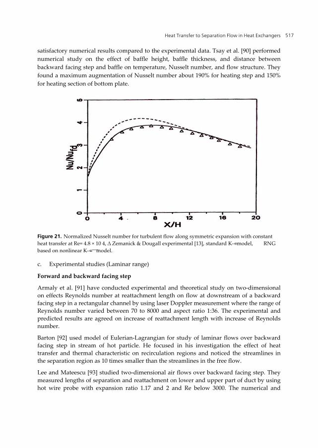
Some researchers have used finite volume methods to analyze turbulent heat transfer and separated flow, such as Zigh [83] presented computational study of simultaneous heat and mass transfer in turbulent separated flows. It is observed that the location of the maximum Nusselt number is better predicated by the RNG based nonlinear K-∈ model, which has a good agreement with results of Zemanick and Dougall [13] as presented in Figure 21.
Yin et al. [85] numerically calculated the turbulent heat transfer in high Prandtl number fluids by using the two equations turbulence model developed from the model of Nagano and Kim [86] and have compared the numerical results with existing experimental data on water, aqueous ethylene glycol, oil and also obtained a good agreement with experimental data especially with the data of water. Dutta and Acharya [87] performed comparative study on the standard k-t model, nonlinear k-∈ turbulence model, and the modified k-∈ turbulence model for analysis of heat transfer and flow in a backstep, where they found the nonlinear k-∈ and modified models agree batter with the experimental data than the standard k-t model. Rhee and Sung [88] also developed a low Reynolds number kθ-εθ model that dealt with turbulent separated flow and heat transfer [89] and they obtained
Heat Transfer to Separation Flow in Heat Exchangers 517
satisfactory numerical results compared to the experimental data. Tsay et al. [90] performed numerical study on the effect of baffle height, baffle thickness, and distance between backward facing step and baffle on temperature, Nusselt number, and flow structure. They found a maximum augmentation of Nusselt number about 190% for heating step and 150% for heating section of bottom plate.
Figure 21. Normalized Nusselt number for turbulent flow along symmetric expansion with constant heat transfer at Re= 4.8 × 10 4, ∆ Zemanick & Dougall experimental [13], standard K-∈ model, �� RNG based on nonlinear K-∈ ─ model.
c. Experimental studies (Laminar range)
Forward and backward facing step
Armaly et al. [91] have conducted experimental and theoretical study on two-dimensional on effects Reynolds number at reattachment length on flow at downstream of a backward facing step in a rectangular channel by using laser Doppler measurement where the range of Reynolds number varied between 70 to 8000 and aspect ratio 1:36. The experimental and predicted results are agreed on increase of reattachment length with increase of Reynolds number.
Barton [92] used model of Eulerian-Lagrangian for study of laminar flows over backward facing step in stream of hot particle. He focused in his investigation the effect of heat transfer and thermal characteristic on recirculation regions and noticed the streamlines in the separation region as 10 times smaller than the streamlines in the free flow.
Lee and Mateescu [93] studied two-dimensional air flows over backward facing step. They measured lengths of separation and reattachment on lower and upper part of duct by using hot wire probe with expansion ratio 1.17 and 2 and Re below 3000. The numerical and
An Overview of Heat Transfer Phenomena 518
experimental results agree with previous experimental data for separation and reattachment lengh and locations on the lower and upper wall of the duct. Stüer et al. [94] presented experimental study of laminar separation flow on forward facing step by using particle tracking velocimetry to get more information about separation phenomena. They observed the increase of distance between the breakthroughs in span with decrease of Reynolds number. Armaly et al. [95] adopted experimental measurements of velocity in three dimensional laminar separated flows on backward facing step by using two components laser Doppler velocimeter with expansion ratio of 2.02 and the range of Reynolds number from 98.5 to 525 and observed increase of recirculation regions with increase of Reynolds number. Velazquez et al. [96] presented study of enhancements of heat transfer for laminar flow over a backward facing step by using pulsating flow. They showed at Re=100, the maximum time average Nusselt number was 55% higher in comparison to steady case.
d. Numerical studies (Laminar range)
Forward and backward facing step
Han et al. [97] carried out numerical study of incompressible laminar flow through 90 degree diversions of rectangular cross section. They showed that, with the increase of aspect ratio of duct the distance between top and bottom of symmetry plane effect the flow. Rouizi et al. [98] investigated numerically, the two-dimensional incompressible laminar flows over backward facing step. They employed model reduction and identification technique with finite element method and observed that with the increase model order the accuracy increases. They have also validated the length of recirculation bubble by reduced order model and obtained good agreement with previous studies.
Li and Armaly [99] presented result of laminar mixed convection in 3D backward facing step by solving the fill elliptic 3 coupled governing equation by using finite volume method. They found the effect of buoyancy force and temperature on reattachment length.
Saldana et al. [100] conducted numerical study on three-dimensional mixed laminar air flow over horizontal backward step by using finite volume method. The bottom wall of channel was heated at constant temperature and the other walls were adiabatic, the aspect ratio maintained as 4 and range of Richardson number (Ri) varied between 0 to 3. The numerical results showed the decrease of size of primary recirculation region and rarefaction of maximum value of average Nusselt number with the increase of Richardson number.
Lima et al. [101] investigated two-dimension laminar air flows over backward facing step by using two CFD commercial codes, the first one based on finite element method (comsol multiphysics) and the other one finite volume method (Fluent) at a range of Reynolds number. The numerical results agreed with the previous experimental data.
7. Remarks
Separation flow along with heat transfer and pressure drop phenomena are described in the present chapter. Different channel configurations for laminar and turbulent flow have
Heat Transfer to Separation Flow in Heat Exchangers 519
studied to find the optimum heat transfer and pressure loss configurations. Numerical and experimental studies have been conducted to find out selected models for good estimation of heat transfer and friction loss.
Nomenclature
3D A As CRZ Cf D ER h H Hr K Ka Nu NuDB Pr Re Tb Ts Uref Vs
Ψ∗
three-dimensional drag surface of the obstacle Surfaces area Corner recirculation zone Friction factor coefficient Diameter of heated tube in the sudden expansion region Expansion ratio Heat transfer coefficient Height Height ratio Thermal conductivity Thermal conductivity of air Nusselt number Nusselt number determined by by Dittus-Boelter Prandtl number Reynold number Air bulk temperature Surface temperature Free stream velocity Voltage turbulent boundary layer thickness energy dissipation rate = / = / Cylinder angle measured from stagnation point Ψ∗ = Ψ/
m2 m2 m W/ m2.K
mm W/m.K W/m.K °C m/sec Volt M m2/s3
Author details
S. N. Kazi, Hussein Togun and E. Sadeghinezhad Department of Mechanical Engineering, Faculty of Engineering, University of Malaya, Kuala Lumpur, Malaysia
An Overview of Heat Transfer Phenomena 520
8. References
[1] Charwat, A. and C. Dewey, An investigation of separated flows part II: flow in the cavity and heat transfer. Journal of Aerospace Seience, 1961. 28(1): p. 513-527.
[2] Low, G.M., The compressible laminar boundary layer with fluid injection. NACA TN, 1955. 3404.
[3] Illingworth, C., The effect of heat transfer on the separation of a compressible laminar boundary layer. The Quarterly Journal of Mechanics and Applied Mathematics, 1954. 7(1): p. 8-34.
[4] Gadd, G., Boundary Layer Separation in the Presence of Heat Transfer, 1960, DTIC Document.
[5] Boelter, L., G. Young, and H. Iversen, An Investigation of Aircraft Heaters, XXVII±Distribution of Heat-transfer Rate in the Entrance Section of a Circular Tube, National Advisory Committee for Aeronautics, 1948, Technical Note.
[6] Ede, A., C. Hislop, and R. Morris, Effect on the local heat-transfer coefficient in a pipe of an abrupt disturbance of the fluid flow: abrupt convergence and divergence of diameter ratio 2/1. Proceedings of the Institution of Mechanical Engineers, 1956. 170(1): p. 1113-1130.
[7] Koram, K. and E. Sparrow, Turbulent heat transfer downstream of an unsymmetric blockage in a tube. Journal of heat transfer, 1978. 100: p. 588.
[8] Krall, K. and E.M. Sparrow, Turbulent heat transfer in the separated, reattached, and redevelopment regions of a circular tube. Journal of heat transfer, 1966. 88: p. 131.
[9] Suzuki, K., et al., Heat Transfer in the Downstream Region of an Orifice in a Tube. Trans. JSME B, 1982. 48: p. 132-140.
[10] Filetti, E. and W.M. Kays, Heat transfer in separated, reattached, and redevelopment regions behind a double step at entrance to a flat duct. Journal of heat transfer, 1967. 89: p. 163.
[11] Seki, N., S. Fukusako, and T. Hirata, Effect of stall length on heat transfer in reattached region behind a double step at entrance to an enlarged flat duct. International Journal of Heat and Mass Transfer, 1976. 19: p. 700-702.
[12] Seki, N., S. Fukusako, and T. Hirata, Turbulent fluctuations and heat transfer for separated flow associated with a double step at entrance to an enlarged flat duct. Journal of heat transfer, 1976. 98: p. 588.
[13] Zemanick, P.P. and R.S. Dougall, Local heat transfer downstream of abrupt circular channel expansion. Journal of heat transfer, 1970. 92: p. 53.
[14] Smyth, R., Heat transfer in turbulent separated flow. J. Nucl. Sci. Technol.(Tokyo), v. 11, no. 12, pp. 545-553, 1974. 11(12).
[15] Baughn, J., et al., Local heat transfer downstream of an abrupt expansion in a circular channel with constant wall heat flux. Journal of heat transfer, 1984. 106: p. 789.
[16] Runchal, A., Mass transfer investigation in turbulent flow downstream of sudden enlargement of a circular pipe for very high Schmidt numbers. International Journal of Heat and Mass Transfer, 1971. 14(6): p. 781-792.
Heat Transfer to Separation Flow in Heat Exchangers 521
[17] Baughn, J., et al., Heat transfer, temperature, and velocity measurements downstream of an abrupt expansion in a circular tube at a uniform wall temperature. Journal of heat transfer, 1989. 111: p. 870.
[18] Baughn, J., et al. Turbulent velocity and temperature profiles downstream of an abrupt expansion in a circular duct with a constant wall temperature. 1987.
[19] Baughn, J., et al., Heat transfer downstream of an abrupt expansion in the transition Reynolds number regime. Journal of heat transfer, 1987. 109: p. 37.
[20] Baughn, J., et al., Local heat transfer measurements using an electrically heated thin gold-coated plastic sheet. Journal of heat transfer, 1985. 107: p. 953.
[21] Iguchi, M. and T. Sugiyama, Study on the flow near the wall of the larger pipe, downstream of a sudden expansion. Trans JSME B, 1988. 54(507): p. 3010-3015.
[22] Habib, M., et al., An experimental investigation of heat-transfer and flow in channels with streamwise-periodic flow. Energy, 1992. 17(11): p. 1049-1058.
[23] Habib, M., et al., Experimental investigation of heat transfer and flow over baffles of different heights. ASME Transactions Journal of Heat Transfer, 1994. 116: p. 363-368.
[24] Chieng, C. and B. Launder, On the calculation of turbulent heat transport downstream from an abrupt pipe expansion. Numerical Heat Transfer, 1980. 3(2): p. 189-207.
[25] Gooray, A., C. Watkins, and W. Aung, Turbulent heat transfer computations for rearward-facing steps and sudden pipe expansions. Journal of heat transfer, 1985. 107: p. 70.
[26] Aung, W. and R. Goldstein, Heat transfer in turbulent separated flow downstream of a rearward-facing step. Israel journal of technology, 1972. 10(1-2): p. 35-41.
[27] Sparrow, E. and J. O’Brien, Heat Transfer Coefficients on the Downstream Face of an Abrupt Enlargement or Inlet Constriction in a Pipe. Journal of heat transfer, 1980. 102: p. 408.
[28] Moss, W. and S. Baker, Re-circulating flows associated with two-dimensional steps. Aeronautical Quarterly, 1980. 31: p. 151-172.
[29] Eaton, J.K. and J. Johnston, Turbulent flow reattachment: an experimental study of the flow and structure behind a backward-facing step, 1980, Stanford University.
[30] Habib, M., A. Attya, and D. McEligot, Calculation of turbulent flow and heat transfer in channels with streamwise-periodic flow. Journal of turbomachinery, 1988. 110: p. 405.
[31] Habib, M., F. Durst, and D. McEligot. Streamwise-periodic flow around baffles. 1985. [32] Berner, C., F. Durst, and D. McEligot, Flow around baffles. Journal of heat transfer, 1984.
106: p. 743. [33] Kim, K.Y. and Y.J. Lee, Prediction of turbulent heat transfer downstream of an abrupt pipe
expansion. Journal of Mechanical Science and Technology, 1994. 8(3): p. 248-254. [34] Chung, B.T.F. and S. Jia, A turbulent near-wall model on convective heat transfer from an
abrupt expansion tube. Heat and Mass Transfer, 1995. 31(1): p. 33-40. [35] Hsieh, W. and K. Chang, Calculation of wall heat transfer in pipeexpansion turbulent flows.
International Journal of Heat and Mass Transfer, 1996. 39(18): p. 3813-3822. [36] Launder, B. and B. Sharma, Application of the energy-dissipation model of turbulence to the
calculation of flow near a spinning disc. Letters Heat Mass Transfer, 1974. 1: p. 131-137.
An Overview of Heat Transfer Phenomena 522
[37] Bremhorst, K., Modified form of the kw model for predicting wall turbulence. Journal of Fluid Engineering, 1981. 103: p. 456-460.
[38] Chien, K.Y. Predictions of channel and boundary-layer flows with a low-Reynolds-number two-equation model of turbulence. 1980.
[39] Nagano, Y. and M. Hishida, Improved form of the k-∈ model for wall turbulent shear flows. Journal of fluids engineering, 1987. 109: p. 156.
[40] Abe, K., T. Kondoh, and Y. Nagano, A new turbulence model for predicting fluid flow and heat transfer in separating and reattaching flows—II. Thermal field calculations. International Journal of Heat and Mass Transfer, 1995. 38(8): p. 1467-1481.
[41] Chang, K., W. Hsieh, and C. Chen, A modified low-Reynolds-number turbulence model applicable to recirculating flow in pipe expansion. Journal of fluids engineering, 1995. 117: p. 417.
[42] Lam, C.K.G. and K. Bremhorst, A modified form of the k-epsilon model for predicting wall turbulence. ASME, Transactions, Journal of Fluids Engineering, 1981. 103: p. 456-460.
[43] Myong, H.K. and N. Kasagi, A new approach to the improvement of k-ε turbulence model for wall-bounded shear flows. JSME Int. J., 1990. 33: p. 63–72.
[44] Shih, T.H., et al., A new k-[epsilon] eddy viscosity model for high reynolds number turbulent flows. Computers & Fluids, 1995. 24(3): p. 227-238.
[45] Guo, Z.Y., D.Y. Li, and X.G. Liang, Thermal effect on the recirculation zone in sudden-expansion gas flows. International Journal of Heat and Mass Transfer, 1996. 39(13): p. 2619-2624.
[46] Prud'Homme, M. and S. Elghobashi, Turbulent heat transfer near the reattachment of flow downstream of a sudden pipe expansion. Numerical Heat Transfer, Part A: Applications, 1986. 10(4): p. 349-368.
[47] Moon, L. and G. Rudinger, Velocity distribution in an abruptly expanding circular duct. Journal of Fluids Engineering, 1977. 99: p. 226.
[48] Huang, Z., et al., Combustion behaviors of a compression-ignition engine fuelled with diesel/methanol blends under various fuel delivery advance angles. Bioresource Technology, 2004. 95(3): p. 331-341.
[49] Sugawara, K., H. Yoshikawa, and T. Ota. LES of Three-Dimensional Separated Flow and Heat Transfer in a Symmetric Expansion Plane Channel. 2004. Japan Heat Transfer Society; 1999.
[50] Yoshikawa, H., K. Ishikawa, and T. Ota. Numerical Simulation of Three-Dimensional Separated Flow and Heat Transfer in an Enlarged Rectangular Channel. 2004. Japan Heat Transfer Society; 1999.
[51] Yoshikawa, H., M. Yoshikawa, and T. Ota. Numerical Simulation of Heat Transfer in Unsteady Separated and Reattached Flow Around a Symmetric Sudden Expansion Channel. 2002. Japan Heat Transfer Society; 1999.
Heat Transfer to Separation Flow in Heat Exchangers 523
[52] OTA, T., et al., Numerical Analysis of Separated Flow and Heat Transfer in an Enlarged Channel. Transactions of the Japan Society of Mechanical Engineers. B, 2000. 66(648): p. 2109-2116.
[53] Macagno, E.O. and T.K. Hung, Computational and experimental study of a captive annular eddy. Journal of fluid Mechanics, 1967. 28(01): p. 43-64.
[54] Durst, F., A. Melling, and J. Whitelaw, Low Reynolds number flow over symmetric sudden expansion. 1974.
[55] Goharzadeh, A. and P. Rodgers, Experimental Measurement of Laminar Axisymmetric Flow Through Confined Annular Geometries With Sudden Inward Expansion. Journal of Fluids Engineering, 2009. 131: p. 124501.
[56] Nag, D. and A. Datta, On the eddy characteristics of laminar axisymmetric flows through confined annular geometries with inward expansion. Proceedings of the Institution of Mechanical Engineers, Part C: Journal of Mechanical Engineering Science, 2007. 221(2): p. 213.
[57] Chiang, T., T.W.H. Sheu, and S. Wang, Side wall effects on the structure of laminar flow over a plane-symmetric sudden expansion. Computers & fluids, 2000. 29(5): p. 467-492.
[58] Fearn, R., T. Mullin, and K. Cliffe, Nonlinear flow phenomena in a symmetric sudden expansion. J. Fluid Mech, 1990. 211(595-608): p. C311.
[59] Boughamoura, A., H. Belmabrouk, and S. Ben Nasrallah, Numerical study of a piston-driven laminar flow and heat transfer in a pipe with a sudden expansion. International Journal of Thermal Sciences, 2003. 42(6): p. 591-604.
[60] Pinho, F., P. Oliveira, and J. Miranda, Pressure losses in the laminar flow of shear-thinning power-law fluids across a sudden axisymmetric expansion. International Journal of Heat and Fluid Flow, 2003. 24(5): p. 747-761.
[61] Thiruvengadam, M., B. Armaly, and J. Drallmeier, Three dimensional mixed convection in plane symmetric-sudden expansion: Symmetric flow regime. International Journal of Heat and Mass Transfer, 2009. 52(3-4): p. 899-907.
[62] Seban, R., A. Emery, and A. Levy, Heat transfer to separated and reattached subsonic turbulent flows obtained downstream of a surface step. J. Aerospace Sci, 1959. 26: p. 809-814.
[63] Seban, R., The Effect of Suction and Injection on the Heat Transfer and Flow in a Turbulent Separated Airflow. Journal of heat transfer, 1966. 88: p. 276.
[64] Togun, H., S. Kazi, and A. Badarudin, A Review of Experimental Study of Turbulent Heat Transfer in Separated Flow. Australian Journal of Basic and Applied Sciences, 2011. 5(10): p. 489-505.
[65] Sogin, H.H., A summary of experiments on local heat transfer from the rear of bluff obstacle to a law speed Air stream. Aournal of heat transfer-transactions of the ASME, 1964. 86: p. 200-202.
[66] Mori, Y., Y. Uchida, and K. Sakai, A study of the time and spatial micro-structure of heat transfer performance near the reattaching point of separated flows. Trans. JSME Ser. B, 1986. 52: p. 481.
An Overview of Heat Transfer Phenomena 524
[67] Kawamura, T., et al., Temporal and spatial characteristics of heat transfer at the reattachment region of a backward-facing step. Experimental Heat Transfer, 1987. 1(4): p. 299-313.
[68] Kawamura, T., et al. Time and spatial characteristics of heat transfer at the reattachment region of a two-dimensional backward-facing step. 1991. American Society of Mechanical Engineers.
[69] Abu-Mulaweh, H.I., Turbulent mixed convection flow over a forward-facing step—the effect of step heights. International Journal of Thermal Sciences, 2005. 44(2): p. 155-162.
[70] Sano, M., I. Suzuki, and K. Sakuraba, Control of turbulent channel flow over a backward-facing step by suction. Journal of Fluid Science and Technology, 2009. 4(1): p. 188-199.
[71] Shisnov, E., et al., Heat transfer in the recirculating region formed by a backward-facing step. International Journal of Heat and Mass Transfer, 1988. 31(8): p. 1557-1562.
[72] Etheridge, D. and P. Kemp, Measurements of turbulent flow downstream of a rearward-facing step. Journal of Fluid Mechanics, 1978. 86(03): p. 545-566.
[73] Moss, W., S. Baker, and L. Bradbury. Measurements of mean velocity and Reynolds stresses in some regions of recirculating flow. 1977.
[74] Abbott, D. and S. Kline, Experimental investigation of subsonic turbulent flow over single and double backward facing steps. Journal of basic engineering, 1962. 84: p. 317.
[75] Tani, I., M. Iuchi, and H. Komoda, Experimental investigation of flow separation associated with a step or a groove. Aeronautical Res. Inst. Univ. of Tokyo, Rept, 1961. 364.
[76] Eaton, J. and J. Johnston. A review of research on subsonic turbulent-flow reattachment. 1980.
[77] Smyth, R., Turbulent flow over a plane symmetric sudden expansion. Journal of fluids engineering, 1979. 101: p. 348.
[78] Seban, R., Heat transfer to the turbulent separated flow of air downstream of a step in the surface of a plate. Journal of heat transfer, 1964. 86: p. 259.
[79] Youssef, M., Y. Nagano, and M. Tagawa, A two-equation heat transfer model for predicting turbulent thermal fields under arbitrary wall thermal conditions. International Journal of Heat and Mass Transfer, 1992. 35(11): p. 3095-3104.
[80] Heyerichs, K. and A. Pollard, Heat transfer in separated and impinging turbulent flows. International Journal of Heat and Mass Transfer, 1996. 39(12): p. 2385-2400.
[81] Kader, B., Temperature and concentration profiles in fully turbulent boundary layers. International Journal of Heat and Mass Transfer, 2006. 24(9): p. 1541-1544.
[82] Jayatillaka, C., The influence of prandtl number and surface roughness on the resistances of the laminar sub-layer to momentum and heat transfer. Prog. Heat Mass Transfer, 1969. 1: p. 193-329.
[83] Zigh, A., Computational study of simultaneous heat and mass transfer in turbulent separated flows. 1993.
[84] Kim, J., S. Kline, and J. Johnston, Investigation of a reattaching turbulent shear layer: flow over a backward-facing step. Journal of Fluids Engineering, 1980. 102: p. 302.
Heat Transfer to Separation Flow in Heat Exchangers 525
[85] Yin, Y., Y. Nagano, and M. Tagawa, Numerical prediction of turbulent heat transfer in high-Prandtl-number fluids. JSME Transactions, 1992. 58: p. 2254-2260.
[86] Nagano, Y. and C. Kim, A two-equation model for heat transport in wall turbulent shear flows. Journal of heat transfer, 1988. 110: p. 583.
[87] Dutta, S. and S. Acharya, Heat Transfer and Flow Past a Backstep with the Nonlinear k-∈ Turbulence Model and the Modified k-∈ Turbulence Model. Numerical Heat Transfer, Part A Applications, 1993. 23(3): p. 281-301.
[88] Rhee, G.H. and H.J. Sung, A nonlinear low-Reynolds-number k-∈ model for turbulent separated and reattaching flows - II. Thermal field computations. International Journal of Heat and Mass Transfer, 1996. 39(16): p. 3465-3474.
[89] Park, T.S. and H.J. Sung, A nonlinear low-Reynolds-number κ-ε model for turbulent separated and reattaching flows—I. Flow field computations. International Journal of Heat and Mass Transfer, 1995. 38(14): p. 2657-2666.
[90] Tsay, Y.L., T. Chang, and J. Cheng, Heat transfer enhancement of backward-facing step flow in a channel by using baffle installation on the channel wall. Acta mechanica, 2005. 174(1): p. 63-76.
[91] Armaly, B., et al., Experimental and theoretical investigation of backward-facing step flow. Journal of Fluid Mechanics, 1983. 127(1): p. 473-496.
[92] Barton, I., Laminar flow over a backward-facing step with a stream of hot particles. International Journal of Heat and Fluid Flow, 1997. 18(4): p. 400-410.
[93] Lee, T. and D. Mateescu, Experimental and numerical investigation of 2-D backward-facing step flow. Journal of Fluids and Structures, 1998. 12(6): p. 703-716.
[94] Stüer, H., A. Gyr, and W. Kinzelbach, Laminar separation on a forward facing step. European Journal of Mechanics Series B Fluids, 1999. 18: p. 675-692.
[95] Armaly, B., A. Li, and J. Nie, Measurements in three-dimensional laminar separated flow. International Journal of Heat and Mass Transfer, 2003. 46(19): p. 3573-3582.
[96] Velazquez, A., J. Arias, and B. Mendez, Laminar heat transfer enhancement downstream of a backward facing step by using a pulsating flow. International Journal of Heat and Mass Transfer, 2008. 51(7): p. 2075-2089.
[97] Han, J., L. Glicksman, and W. Rohsenow, An investigation of heat transfer and friction for rib-roughened surfaces. International Journal of Heat and Mass Transfer, 1978. 21(8): p. 1143-1156.
[98] Rouizi, Y., et al., Numerical model reduction of 2D steady incompressible laminar flows: Application on the flow over a backward-facing step. Journal of Computational Physics, 2009. 228(6): p. 2239-2255.
[99] Li, A. and B. Armaly, Mixed Convection Adjacent to 3-D Backward-Facing Step. ASME-PUBLICATIONS-HTD, 2000. 366: p. 51-58.
[100] Saldana, J.G.B., N. Anand, and V. Sarin, Numerical simulation of mixed convective flow over a three-dimensional horizontal backward facing step. Journal of heat transfer, 2005. 127: p. 1027.
An Overview of Heat Transfer Phenomena 526
[101] Lima, R., C. Andrade, and E. Zaparoli, Numerical study of three recirculation zones in the unilateral sudden expansion flow. International Communications in Heat and Mass Transfer, 2008. 35(9): p. 1053-1060.


![Heat Transfer to Separation Flow in Heat Exchangers · Heat Transfer to Separation Flow in Heat Exchangers 501 Ede et al. [6] have investigated the effect of an abrupt convergence](https://static.documents.pub/doc/80x56/5eabd6fac71d690f1442525e/heat-transfer-to-separation-flow-in-heat-exchangers-heat-transfer-to-separation.jpg)


