David shares his insights and opinions on current activities affecting industrial laser materials processing. www.industrial-lasers.com/dabbling.html
Features9 s p e c i a l r e p o r t
2018 was another record year, contending with turmoilIndustrial Laser Solutions expects modest growth to come in 2019 DAVID A. BELFORTE
13 t e c h n o l o g y r e p o r t
The laser: One universal tool for manufacturingWhat does the future hold for lasers in industrial processing? THOMAS GRAF, MARWAN ABDOU AHMED, PETER BERGER, VOLKHER ONUSEIT, AND RUDOLF WEBER
17 t e c h n o l o g y r e p o r t
Fiber laser technology enables zero-gap galvanized steel sheet joiningApproach to fiber laser joining of galvanized steel uses laser beam mode control TAKASHI KAYAHARA, RYOSUKE NISHII, TOMOMICHI YASUOKA, AND TAKASHI SHIGEMATSU
22 a p p l i c a t i o n r e p o r t
Laser heat treatment improves quality in automotive die manufacturingLaser method also demonstrates cost savings for OEMs ARAVIND JONNALAGADDA, MARCUS STACKPOOLE, AND MATTHEW STACKPOOLE
27 t e c h n o l o g y r e p o r t
Extreme high-speed laser material deposition conquers industryProcess yields increased speeds and lower costs over conventional methods THOMAS SCHOPPHOVEN, ANDRES GASSER, AND GERHARD BACKES
30 a p p l i c a t i o n r e p o r t
Laser welding at the green wavelength bene� ts electri� ed mobility applicationsGreen wavelength yields process stability, high absorption, and high feed rates HENRIKKI PANTSAR, EVA-MARIA DOLD, MARC KIRCHHOFF, AND OLIVER BOCKSROCKER
33 a p p l i c a t i o n r e p o r t
Advanced manufacturing solutions for automotive powertrain productionPost-process inspection method enables 100% traceability ANDREAS MOOTZ
updateProject works to develop laser welding processes for thick metal sheetsHANNOVER, GERMANY – A joint project led by Laser Zen-trum Hannover (LZH), together with electronics manu-facturer Held Systems Deutschland (Heusenstamm, Ger-many), industrial laser maker Laserline (Mülheim-Kärlich, Germany) and shipbuilder Meyer Werft (Papenburg, Ger-many), is working to establish robust, pure laser weld-ing processes for steel sheet thicknesses up to 30 mm. For this purpose, the team members are bringing diode laser beam sources to peak performance.
Processes for joining maritime steel components have great development potential in terms of pro-duction costs and productiv-ity (FIGURE 1). The frequently used submerged arc weld-ing process is comparatively slow and involves signi� cant workpiece distortion, and an alternative process called laser-arc hybrid welding requires labor-intensive edge preparation and is not very � exible.
For large steel sheet thicknesses ranging from 12 to 30 mm in particular, no method has been able to prevail against submerged arc welding. Recognizing this, the proj-ect members want to develop robust, pure laser welding
processes for thick metal sheet welding in the maritime sector. In the project dubbed Thick Metal Sheet Welding by High-Power Diode Lasers for Maritime Applications (DIOMAR), Laserline will develop new diode laser beam sources with maximum output power up to 60 kW in con-tinuous-wave mode. The aim of the DIOMAR project is to achieve high-quality joints with high welding speeds, and
the partners want to reduce the costs for edge preparation and the amount of additional mate-rial compared to existing joining methods (FIGURE 2).
The application-oriented development takes place in par-allel in a laser laboratory and in a shipyard-like test environment, making it possible to quickly test, evaluate, and optimize processes.
For more information, please visit www.lzh.de. ✺
FIGURE 1. New laser welding processes will make welding of thick metal sheets in shipbuilding more ef� cient and less expensive. (Copyright: Meyer Werft/M. Wessels)
FIGURE 2. The aim of the DIOMAR project is to establish new laser welding processes based on high-power lasers in the maritime sector. (Copyright: Meyer Werft/I. Fiebak)
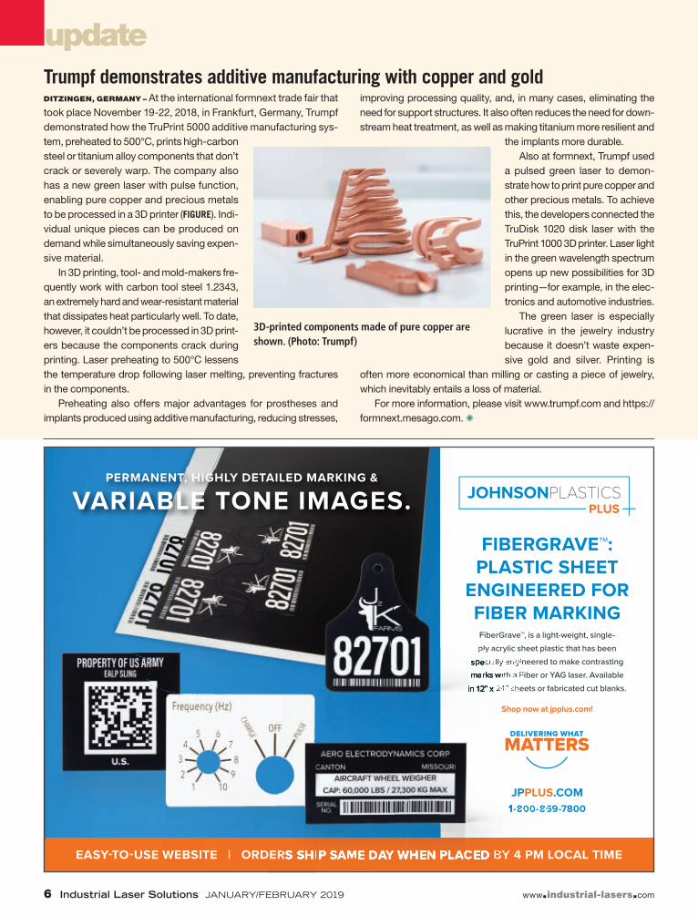
updateTrumpf demonstrates additive manufacturing with copper and goldDITZINGEN, GERMANY – At the international formnext trade fair that took place November 19-22, 2018, in Frankfurt, Germany, Trumpf demonstrated how the TruPrint 5000 additive manufacturing sys-tem, preheated to 500°C, prints high-carbon steel or titanium alloy components that don’t crack or severely warp. The company also has a new green laser with pulse function, enabling pure copper and precious metals to be processed in a 3D printer (FIGURE). Indi-vidual unique pieces can be produced on demand while simultaneously saving expen-sive material.
In 3D printing, tool- and mold-makers fre-quently work with carbon tool steel 1.2343, an extremely hard and wear-resistant material that dissipates heat particularly well. To date, however, it couldn’t be processed in 3D print-ers because the components crack during printing. Laser preheating to 500°C lessens the temperature drop following laser melting, preventing fractures in the components.
Preheating also offers major advantages for prostheses and implants produced using additive manufacturing, reducing stresses,
improving processing quality, and, in many cases, eliminating the need for support structures. It also often reduces the need for down-stream heat treatment, as well as making titanium more resilient and
the implants more durable.Also at formnext, Trumpf used
a pulsed green laser to demon-strate how to print pure copper and other precious metals. To achieve this, the developers connected the TruDisk 1020 disk laser with the TruPrint 1000 3D printer. Laser light in the green wavelength spectrum opens up new possibilities for 3D printing—for example, in the elec-tronics and automotive industries.
The green laser is especially lucrative in the jewelry industry because it doesn’t waste expen-sive gold and silver. Printing is
often more economical than milling or casting a piece of jewelry, which inevitably entails a loss of material.
For more information, please visit www.trumpf.com and https://formnext.mesago.com. ✺
3D-printed components made of pure copper are shown. (Photo: Trumpf)
With its fully reflective design, the excelliSHIFT optical Z-axis smashes 3D-processing dynamics records:
• Up to 5x faster than a varioSCAN 20
• Ideal in combination with excelliSCAN and intelliSCAN scan heads
• Suitable for IR and SHG lasers
• Extends 2D scan heads into 3D scan systems
For more information, simply contact us via info scanlab.de
www.scanlab.de
Visit us atPhotonics West 2019, Booth #2251San Francisco, CA • February 5 – 7
High Speed for the Third Dimension
Scanlab_ILS_1901 1 12/3/18 9:29 AM
update
www.industrial-lasers.com
Additive Manufacturing Users Group selects Gideon Levy for 2019 Innovators AwardMILWAUKEE, WI – The Additive Manufacturing Users Group (AMUG) has named Gideon Levy as the recipient of its esteemed Inno-vators Award, which recognizes those who have cultivated inno-vative ideas that in turn have advanced the additive manufac-turing industry. The Innovators Award will be presented at the
2019 AMUG Conference, to take place March 31–April 4 in Chicago, IL, following Levy’s onstage appearance during the conference’s Innovators Showcase (FIGURE).
Devoted to advanced R&D in mechanical systems, elec-tronics, and manufacturing, Levy has made significant contributions as both an edu-cator and researcher. Those contributions have earned him many accolades, includ-ing being named a Fellow of CIRP (The International Acad-emy for Production Engineer-ing). Presently, he is a con-sultant with Technology Turn
Around (TTA; Dallas, TX), which focuses on additive manufac-turing, electro-physical, and chemical processes.
Levy’s additive manufacturing activities began in 1997 with the establishment of the Institute for Rapid Product Development (iRPD) at the University of Applied Sciences (St. Gallen, Switzer-land). Over the years, he has made many substantial contributions as a researcher, consultant, and advisor. His early work included the development of selective laser sintering (SLS) materials, including PA 12, which continues to be the most widely used. He has also contributed to technology advancements that span numerous addi-tive manufacturing processes and was an early participant in metal additive manufacturing technologies, starting with beta testing of Concept Laser’s � rst metal laser melting machine.
Levy holds more than 35 patents and has been published in more than 250 scienti� c/technical publications. For his work in advanced manufacturing and additive manufacturing, he has received numerous awards, including AMUG’s Distinguished INovator Operator (DINO) Award, TCT’s Top 25 Most In� uen-tial in RPD&M, SME RTAM’s Industry Achievement Award, Solid Freeform Fabrication Symposium’s FAME Award, and VRAP Con-ference’s Career Award.
For more information, please visit www.amug.com. ✺
Gideon Levy will be presented with AMUG’s Innovators Award following his interview at the group’s Innovators Showcase.
2018 was another record year, contending with turmoilINDUSTRIAL LASER SOLUTIONS EXPECTS
MODEST GROWTH TO COME IN 2019
DAVID A. BELFORTE
N o matter where you looked during 2018, two somewhat-intertwined global economic factors had an adverse effect on the industrial laser market. China, already in the midst of a government effort to reduce a massive indebtedness while still
increasing fiscal stimuli to continue bolstering developing indus-trial laser system exports, was hit by the preliminary results of a trade war spat with the U.S. that started affecting manufacturing output in the second half of the year. What, you may ask, does this have to do with total industrial laser revenues for the year?
China is the single largest market for industrial laser prod-ucts, with about an estimated third of all industrial lasers—mostly fiber lasers—being imported into or built in that country to power the several thousands of sheet metal cutting sys-tems produced domestically or exported to the Association of Southeast Asian Nations (ASEAN), India, and increasingly into Western world markets. This fulfills government dictates for expanding Chinese exports of machines, integrated with domestic IP technology. Therefore, some of the economic pain being felt by these companies as investment funds to shore up IP funding became difficult to obtain.
Furthermore, global suppliers of imported industrial lasers, from Europe and the United States, took a double hit from this slowdown in Chinese capital investments and, increas-ingly, from the fallout of a series of targeted tariffs insti-tuted by the U.S. government. For example, about a third of
global industrial laser products were exported to China (the Mechanical Engineering Industry Association [VDMA] has noted that German laser exports to China are more than 30% of the total), and as leading fiber laser manufacturer IPG Photonics stated, China “…remains our largest and most competitive market.” Also, currency exchange woes plagued company CFOs, leading to more mitigation statements from CEOs.
As Industrial Laser Solutions went to press in late 2018, it appears that the U.S. and China have agreed to a rapproche-ment on the issues of trade, which might lead to an easing of tar-iff barriers. However, the impact of tariffs has already negatively affected 2018 industrial laser revenue numbers, and it is too soon to predict a change in ILS’ projected 2019 revenue numbers.
A record out of a market uncertainty
So, identifying uncontrollable causative actions for second-half lethargy in the market, 2018 was another record year for indus-trial laser revenues. Led by gains in high-power fiber and exci-mer laser sales, company revenues cracked the $5-billion level. Looking back to 1970, the date ILS establishes as the beginning of the industrial laser business, revenues have grown a healthy 17.73% in compound annual growth rate (CAGR). And over these 48 years, only four serious downturns affected annual growth: in fact, since the 2009 recession when revenues dipped by up to 60%, the CAGR in more current dollars was 15.18%.
With the above out of the way, it’s appropriate to review ILS’ late-2017 estimates for 2018 annual revenues. Because of a quirk in the timing of official public-company quarterly
economic reports, analysts have to rely on corporate guidance for end-of-year reports. As 2017 drew to a close, ILS, in an established process, used the midpoint of company revenue and growth rate guidance ranges to arrive at an estimate for 2018 revenues in the economic report for the January/February 2019 issue. As a conse-quence, the four Billion-dollar Club industrial laser companies turned in a greater-than-anticipated final quarter with very strong double-digit growth rates, making our mid-single-digit estimate look anemic.
This double whammy, with a currency twist, led to industry man-agement adjusting forecasts in the second half to a level below ILSearly 2018 estimates of 7%. Faced with a possible, but less likely, repeat in 2019, ILS went ahead with revised 2017 market numbers and arrived at an estimate of a nominal 5% gain in total 2018 indus-trial laser revenues. The revised (upward) total revenues in FIGURE 1
are about $4.9 billion (contributing to this increase is very current data from Chinese companies and companies new to the market).
The second-half 2018 market correction led to estimate adjust-ments and total market revenues should come in slightly above $5 billion, a 4%+ growth over 2017. As has been the case since the 2009 recession, fiber laser revenue growth was a major contributor.
Laser revenues under pressure
As noted in FIGURE 1, fiber lasers (specifically high-power fiber lasers) dominate industrial laser revenues in 2018, as they have since 2013 when revenues first surpassed the then-leading carbon-dioxide (CO2) lasers. In 2018, fiber lasers passed the 50% market share level—a remarkable 25.35% CAGR. After several years of superheated annual growth rates, as the high-power fiber laser became a more cost-effec-tive alternative to high-power CO2 lasers for sheet metal cutting appli-cations, the 2018 annual growth rate settled into a more single-digit growth rate commensurate with annual systems sales demand.
CO2 laser revenues dropped to the second highest revenue spot in 2017 and surrendered that position to other laser types this year and are projected to repeat in 2019.
Solid-state lasers, including the high-power disk laser, along with high-power diode and excimer lasers assumed the second and third revenue spots in 2018. Ultrashort-pulse (USP) solid-state lasers began to find multiple high-volume uses in new UV and fem-tosecond applications, showing a 12.8% CAGR since 2014. These lasers are projected to increase their growth rate in 2019. Excimer laser revenues slipped in 2018 as installations for faceplate anneal-ing ramped down, a trend expected to continue in 2019.
Although 2018 proved to be a turbulent year for global manufac-turing economies, and market turmoil brought on by changes in China domestically and in the export/import market caused sec-ond-half revenue adjustments, another record year seems assured (final numbers will be posted in early 2019). And ILS anticipates a continuation of this trend with modest revenue growth in 2019.
Applications growth stabilizes
As seen in FIGURE 2, macromaterial processing, heavily weighted by the slowing of the high-power fiber laser cutting systems mar-ket in China, slipped to a modest 3% growth (more about this later). Micromaterial processing grew by 5%, down from the gritting dou-ble-digit growth of 2017 that was due to one application—excimer laser annealing of silicon for display faceplates. Also, the delivery curve had flattened as planned, and shipments were ramping down.
FIGURE 2 shows that laser marking and engraving is one of only two high-unit-volume fiber laser applications (sheet metal cutting is the other), and is well into the commodity phase with more than 200 systems vendors (25% in China) locked in a selling-price bat-tle covering international markets. CO2 engraving, especially in garment materials, experienced a modest resurgence as fashion changes dictated demand. Together, marking and engraving set-tled at a low-single-digit level, mainly driven by a few new appli-cations—UV laser marking of previously unmanageable materials is one and a growing replacement market. The low-power laser marking and engraving market, most heavily centered in Asia, is a high-volume, low-profit business that for the past two years has been the scene of a bruising selling price battle between domes-tic and imported laser suppliers. For the past two years, marking and engraving laser revenues plateaued around 13%, and expec-tations are that this split will remain in the near-term.
Micro applications
Micromaterial processing, buoyed by deliveries from the faceplate annealing project, held a 32% share of the 2018 total market reve-nues (FIGURE 2), growing 5% over 2017. In the opinion of many knowl-edgeable experts within the industrial laser community, micropro-cessing offers the potential for the strongest growth opportunity over the next few years. Laser microprocessing tends to be more of a global application, with market strength in most established and developing economies.
The faceplate application that drove microprocessing appli-cations in 2017 plateaued as to essentially no revenue growth in 2018. System deliveries achieved planned levels and display apps began the predicted return to normalcy, returning to a modest sin-gle-digit growth in 2019.
A closer look at the micromaterial processing sector for 2018 shows double-digit growth in fine metal and non-metal processing that was able to offset a double-digit decline in additive manufac-turing brought about by temporary overcapacity in key user indus-tries. For 2019, ILS expects a healthy double-digit growth 2019 for additive manufacturing revenues. The solar/other category picked up high single-digit growth as solar installations worldwide had a good year, but not in the U.S. where government support for subsidies was stymied by a lack of administration support. Other laser processes associated with alternate energy technologies are limited in size and currently do not contribute significant revenues. ILS expects the micromaterial sector will experience flat revenues in 2019.
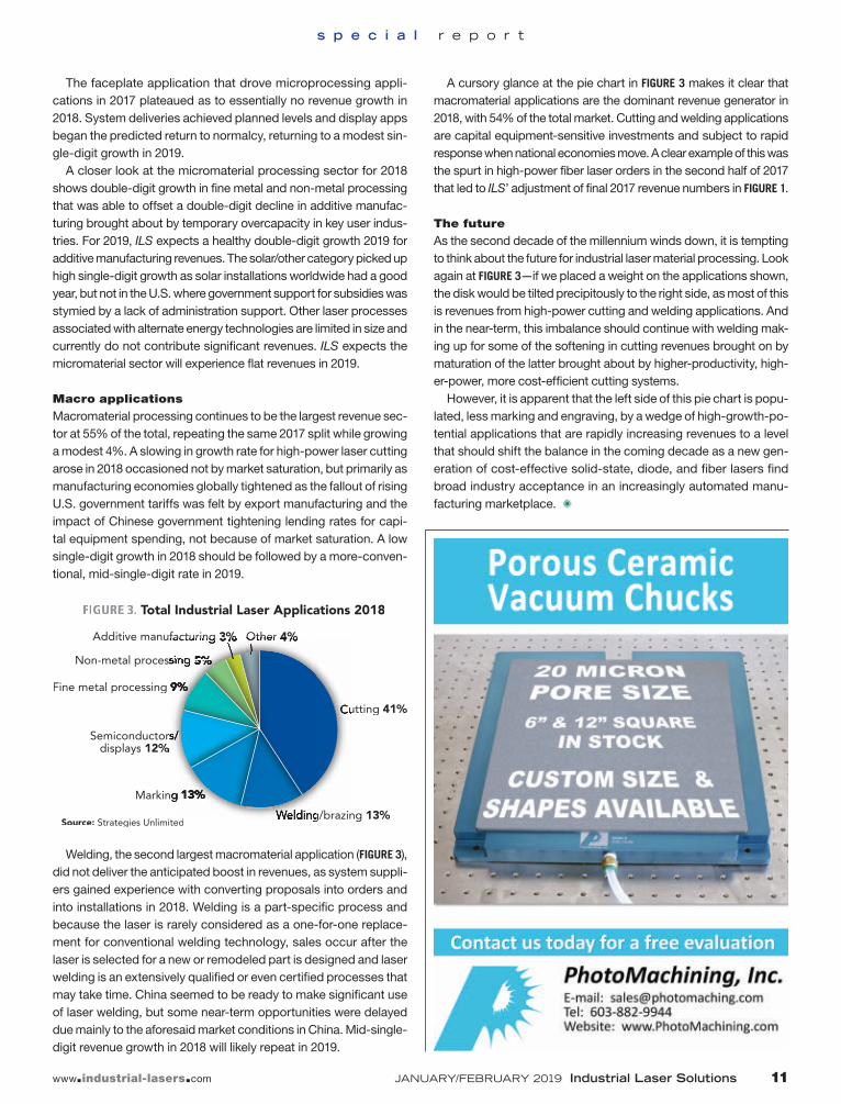
Macro applications
Macromaterial processing continues to be the largest revenue sec-tor at 55% of the total, repeating the same 2017 split while growing a modest 4%. A slowing in growth rate for high-power laser cutting arose in 2018 occasioned not by market saturation, but primarily as manufacturing economies globally tightened as the fallout of rising U.S. government tariffs was felt by export manufacturing and the impact of Chinese government tightening lending rates for capi-tal equipment spending, not because of market saturation. A low single-digit growth in 2018 should be followed by a more-conven-tional, mid-single-digit rate in 2019.
Welding, the second largest macromaterial application (FIGURE 3), did not deliver the anticipated boost in revenues, as system suppli-ers gained experience with converting proposals into orders and into installations in 2018. Welding is a part-specific process and because the laser is rarely considered as a one-for-one replace-ment for conventional welding technology, sales occur after the laser is selected for a new or remodeled part is designed and laser welding is an extensively qualified or even certified processes that may take time. China seemed to be ready to make significant use of laser welding, but some near-term opportunities were delayed due mainly to the aforesaid market conditions in China. Mid-single-digit revenue growth in 2018 will likely repeat in 2019.
A cursory glance at the pie chart in FIGURE 3 makes it clear that macromaterial applications are the dominant revenue generator in 2018, with 54% of the total market. Cutting and welding applications are capital equipment-sensitive investments and subject to rapid response when national economies move. A clear example of this was the spurt in high-power fiber laser orders in the second half of 2017 that led to ILS’ adjustment of final 2017 revenue numbers in FIGURE 1.
The future
As the second decade of the millennium winds down, it is tempting to think about the future for industrial laser material processing. Look again at FIGURE 3—if we placed a weight on the applications shown, the disk would be tilted precipitously to the right side, as most of this is revenues from high-power cutting and welding applications. And in the near-term, this imbalance should continue with welding mak-ing up for some of the softening in cutting revenues brought on by maturation of the latter brought about by higher-productivity, high-er-power, more cost-efficient cutting systems.
However, it is apparent that the left side of this pie chart is popu-lated, less marking and engraving, by a wedge of high-growth-po-tential applications that are rapidly increasing revenues to a level that should shift the balance in the coming decade as a new gen-eration of cost-effective solid-state, diode, and fiber lasers find broad industry acceptance in an increasingly automated manu-facturing marketplace. ✺
THE LASER:One universal tool for manufacturingWHAT DOES THE FUTURE HOLD FOR LASERS
IN INDUSTRIAL PROCESSING?
THOMAS GRAF, MARWAN ABDOU AHMED, PETER
BERGER, VOLKHER ONUSEIT, and RUDOLF WEBER
O ne of the most interesting, but also challenging, aspects of what has been proclaimed as the fourth industrial revolution is that mass personalization requires flexible and reconfig-urable production systems.1
Actually, this was the first time that an industrial revolution—the so-called Industry 4.0—had been announced in advance, but the demand for a universally appli-cable and flexible production tool is an enormous chance for the laser.
For decades, the laser has been known to be a very flexible tool for mate-rials processing that can be used to fulfill a wide variety of manufacturing applica-tions, which in fact cover the complete range of the manufacturing processes defined by the German industry standard DIN 8580. The DIN 8580 groups the pro-cesses into molding, forming, separat-ing, joining, coating, and changing the
material properties (FIGURE 1). In his 1992 textbook, Helmut Hügel already put it this way: “The importance of the laser for industrial manufacturing above all lies in its extraordinary flexi-bility with regard to the various machining processes—cutting, ablation, drilling, welding, hardening, alloying, remelting—as well as with regard to the numerous materials and different workpiece configurations.”2
This is why we have become accustomed to perceiving the laser as a universal production tool. But until now, we always
used quite different lasers for the different applications. The main reason for this is that the physical requirements of the various processes, especially with respect to the fact that aver-age laser power, intensity, pulse duration, and peak intensity or peak fluence and sometimes also the wavelength are quite dif-ferent. The second reason is that so far, the setup of an ultra-short-pulsed laser (USP laser; also known as ultrafast laser) delivering pulses with durations in the picosecond or femto-second ranges differs significantly from a free-running pulsed
EDITOR’S NOTE: To set the tone for a new year in industrial laser technol-ogy, I asked Professor Dr. Thomas Graf, a highly respected advocate of this technology, to share his progres-sive thoughts on the future of lasers in industrial processing.—DAB
FIGURE 1. The laser can be used for materials processing applications that span the whole range of processes as defined by the German Industry Standard DIN 8580.
or continuous-wave (CW) laser. At the same time, the average powers provided by these different lasers were several orders of magnitude apart, with the consequence that microprocessing with USP lasers is yet much less productive than macroprocess-ing with high-power CW lasers.
Extending USP laser
system capabilities
But all of this is about to change. With the average output power of USP lasers just entering the multikilowatt level (FIGURE 2),3-5
the usage of this type of laser is currently being extended beyond the classical micro-processing labs and is indeed conquering large-scale manufacturing applications.6,7 We will therefore see more laser-based, high-precision ultrafast material process-ing being performed on large-scale pro-duction machines that at first sight look quite similar to those we are used to apply-ing to classical macro applications such as cutting or welding (FIGURE 3). The thought to perform all known laser materials pro-cessing applications on the same machine therefore comes naturally. But can this be realized with one and the same laser?
Actually, this question is not new. In his presentation at the 11th International Congress LASER held in Munich in 1993,
Prof. Andreas Gebhardt and his colleagues discussed the expectations, especially of small- and medium-sized enterprises, that all the different laser-based manufactur-ing applications should be performed with one and the same laser device8—an expec-tation that remains unfulfilled to this day.
Looking at the modular architecture of modern high-power USP lasers, however, one easily comes to the conclusion that it should be possible to set up a laser that can be switched between different opera-tion modes and that is suitable for all com-mon material processing applications.
Ultrashort-pulsed laser systems pro-viding high average powers are all based on a small seed oscillator and one or more amplification stages (FIGURE 4). The important point is that at high aver-age powers, these amplifiers (such as slab pre-amplifiers and multipass thin-disk power boosters) work equally well for ultrashort pulses or for CW radiation. Therefore, by integrating additional or more flexible seed sources, there is no technical reason that would prevent us to set up one single laser system that can be switched between CW and pulsed or USP operation.
In a first attempt, one may opt to just implement two or more seed sources—for example, an ultrafast mode-locked oscil-lator and a simple CW laser—in the same system. As most systems include a pulse picker to pick the pulses that are launched into the amplifier chain, the same can eas-ily be used to switch between the two seed sources. In a more advanced approach, one would just use one seed that can be
FIGURE 3. A typical installation for remote welding with high-power CW lasers is shown (IFSW, University of Stuttgart); in the future, similar facilities might also be used for highly productive micromaterials processing using kilowatt-class USP lasers.
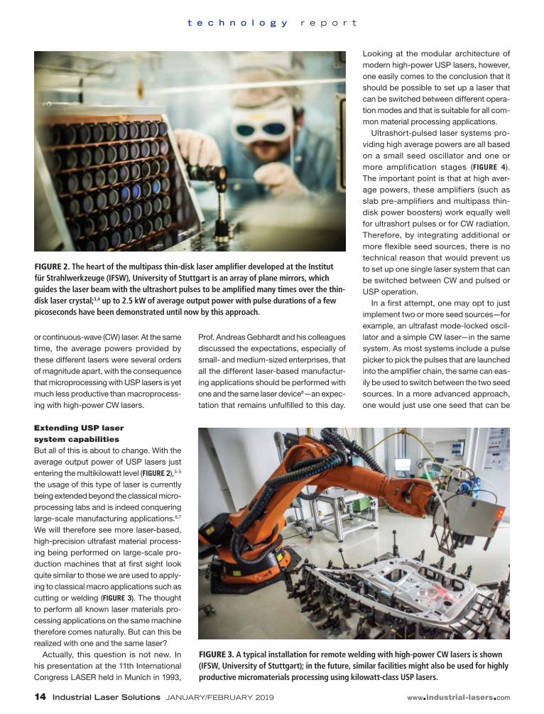
FIGURE 2. The heart of the multipass thin-disk laser amplifier developed at the Institut für Strahlwerkzeuge (IFSW), University of Stuttgart is an array of plane mirrors, which guides the laser beam with the ultrashort pulses to be amplified many times over the thin-disk laser crystal;3,4 up to 2.5 kW of average output power with pulse durations of a few picoseconds have been demonstrated until now by this approach.
operated in different modes (mode-locked, Q-switched, and CW). Even this idea is not much of a revolution anymore since diode lasers that can be switched between differ-ent operation modes are already available.9
Taking the commonly used architecture of current high-power USP lasers a few more steps ahead, we may realize a laser that provides several kilowatts of aver-age output power that can be switched between different operation modes, rang-ing from the delivery of ultrashort pulses to the common CW radiation. Moreover, the high powers or high intensities that are available from the most advanced lasers also make frequency conversion
by nonlinear optical effects increasingly more attractive and efficient (FIGURE 5). We will therefore not only be able to switch between different pulse durations and CW operation, but also between different wave-lengths. This will finally fulfill the expecta-tion that one and the same laser can be used to realize most of the known materi-als processing applications.
What this leads to is a universal machine that can virtually perform the complete range of laser-based manu-facturing processes just by changing its operation parameters. This not only will be the ideal software-controlled universal tool for Industry 4.0, it will definitely also
confirm the other often-cited proclama-tion, namely that the 21st century will be the century of the photon.
Meeting the challenges
Of course, there are still a few challenges along the way. Some are still related to optics, like the desire for fiber-optic beam delivery of high-energy ultrashort pulses. Others concern the system engineering. Thanks to huge progress both on the laser sources and on the fundamental under-standing of the physics of laser materials processing, we know to a large extent how—and with what strategy and with which process parameters—an ideal pro-cess should be performed. Here, the bot-tleneck more often turns out to be the machines themselves. In fact, depending on the planned application, the machines used for laser processing should become either about 100X faster or about 10X more precise.
To reach this goal, we should stop con-sidering laser machines as just being a machine tool with a laser built into it. Instead, we should design laser machines from scratch as a photonic system. This will require new scientific approaches and methods for system engineering and will be the key for the future success of laser-based manufacturing. ✺
REFERENCES
1. See http://bit.ly/ilsref1. 2. H. Hügel, Strahlwerkzeug Laser: eine Einführung, B. G.
Teubner, ISBN 3-519-06134-1 (1992). 3. J.-P. Negel et al., Opt. Express, 23, 16, 21064–21077
2013). 5. M. Müller et al., Opt. Lett., 43, 24, 6037–6040 (Dec. 15,
2018). 6. C. Freitag et al., Appl. Phys. A, 119,1237–1243 (2015);
doi:10.1007/s00339-015-9159-3. 7. S. Faas, U. Bielke, R. Weber, and T. Graf, “Scaling the
productivity of laser structuring processes using picosecond laser pulses at average powers of up to 420 W to produce superhydrophobic surfaces on stainless steel AISI 316L,” accepted for publication in Scientific Reports.
8. J. Gartzen, A. Gebhardt, and H. Lingens, Proc. 11th International Congress LASER, Munich, Germany (Jun. 1993).
9. See www.fbh-berlin.com. 10. T. Dietrich et al., Opt. Express, 25, 5, 4917–4925 (Mar.
6, 2017).
THOMAS GRAF ([email protected]), MARWAN ABDOU AHMED, PETER BERGER, VOLKHER ONUSEIT, and RUDOLF WEBER are all with the Institut für Strahlwerkzeuge (IFSW) at the University of Stuttgart, Stuttgart, Germany; www.ifsw.uni-stuttgart.de. FIGURE 5. Intracavity frequency-doubling of a CW thin-disk laser is shown.10
FIGURE 4. This schematic shows the typical architecture of high-power USP lasers; the same approach might be used to realize a (single) laser system that can be switched between different operation modes and therefore is applicable for all the common material processing applications.
G alvanized steel sheets excel at preventing corrosion, so they are widely used in manufac-turing automobiles, electrical appliances, and building con-struction materials. There are a variety of galvanized
steel sheets depending on the application, such as hot-dip galvanized steel sheets (non-alloyed and alloyed) and electrogalvanized steel sheets.
Spot welding, arc welding, and laser welding are applied when working with these materials. During that time, the process stabilization should be addressed regarding the amount of zinc, con-tents of other elements, and state of adhesion between the galvanization materials and the steel plates.
Spot welding is widely used to weld galvanized steel sheets, especially for car bodies. When the distance between the spots is short, the electri-cal current is dispersed within the joint portion, so creating a strong bonding area may not be possi-ble. For this reason, there are limits on the num-ber and distance between joints, so joint strength between the parts and the rigidity of the vehicle
body are compromised. Laser welding is used as a method to compensate for the disadvantage of spot welding since there is no need to consider the dispersion of electricity.
When laser welding zinc-plated steel, the temperature differ-ence between the melting temperature of steel (over 1500°C) and the boiling temperature of the zinc makes lap welding
difficult.1 Such a difference causes the weld-ing defects to blow away the surrounding mol-ten metal. To solve this problem, a fine bond-ing state is realized by forming a clearance of about 0.1 to 0.2 mm between overlapped galva-nized steel sheets to form escape paths of metal vapor.2 However, precisely controlling the gap of 0.1 to 0.2 mm to stabilize the welding quality is complicated, as the fixing jig restricted the man-ufacturing process and parts shape. In this arti-cle, we introduce a new joining technology that welds various galvanized steel sheets by weld-ing with fiber lasers.
Fiber laser with high beam
quality, beam mode control
Furukawa Electric (Tokyo, Japan) has developed and sold high-power fiber lasers for industrial use for more than 10 years based on semiconductor
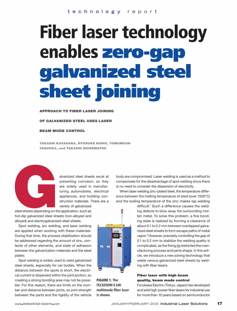
FIGURE 1. The FEC6000M 6 kW multimode fiber laser is shown.
lasers, optical fibers, and its fusing tech-nology that it has applied in the optical communications field. The typical beam characteristic of its fiber laser products is M2~1.06 at single mode up to 1.5 kW, beam parameter product (BPP) ~1.7 mm mrad at 4 kW, and BPP~3.0 mm mrad at 6 kW (FIGURE 1). These fiber lasers feature good beam quality because of the unique struc-ture of the combiner, stable parts quality, and fiber core diameter. The beam quality enables deep penetration depth in weld-ing because of the high power density of the laser light focusing point.
FIGURE 2 shows the penetration depth of bead-on plate for various materials using the 6 kW multimode fiber laser. In the low-speed region where the welding speed is 0.5 m/min, penetration depth of about 12 mm for steel and aluminum and 7.5 mm for pure copper was achieved. In the rela-tively high-speed region where the welding speed was 10 m/min, penetration depth of about 7 mm for steel and aluminum and about 4 mm for pure copper was obtained.
These high power densities contribute to the higher process speed and lower power consumption in welding—however,
they do not always give favorable results in all processing. The laser beam focused at one point causes a rapid temperature change of the material and a severe con-vection inside the molten pool at the pro-cessing point, and the lower stability of the molten pool leads to welding defects such as sputtering and blowholes. As a result, visual inspection and sputter removal pro-cesses are needed. Many production pro-cesses use fiber lasers, so there is keen interest in technology for suppressing these welding defects.
Furukawa Electric, in collaboration with Furukawa Denshi (Fukushima, Japan), developed a beam mode control tech-nology for fiber lasers that can precisely control the power density of the target materials. This technology can be eas-ily integrated into the processing head, including the galvanometer (galvo) scan-ner, because of the very simple optical configuration. Also, the combination is
infinite since the energy bifurcation ratio to be allocated to each point can be freely designed (FIGURE 3). This beam mode con-trol element has sufficient power resis-tance characteristics for multikilowatt output lasers and handling is the same as conventional lenses.
Zero-gap welding of
galvanized steel sheets
Furukawa Electric developed the Laser (Continuous, Close Contact) Welding (LC3W) method, which continuously welds galvanized steel sheets without gaps. FIGURE 4 shows the appearance of welding beads when a galvanized steel sheet was welded by a single spot beam as a conventional method. Welding con-ditions were 3 kW output power and 1.5 m/min welding speed—from this result, it can be inferred that spattering caused by the metal vapor of zinc generated from the overlapped portion of the two galvanized steel sheets caused the voids.
LC3W has proven to be effective for close contact lap welding of several kinds of galvanized steel sheets by beam oscil-lation with a galvo scanner in addition to a special beam mode. It has also demon-strated that it can suppress weld defects for close contact lap welding of several kinds of galvanized steel sheets. FIGURE 5
shows the appearance of the weld bead and a cross-section obtained by lap
FIGURE 5. LC3W results for 1-mm-thick electrogalvanized steel sheet at 3 kW output power and 1.5 m/min welding speed show the welding bead appearance (a) and cross-section (b).
FIGURE 3. The beam mode of the conventional single-spot (a), center and ring shape (b), and line shape (c) are shown.
FIGURE 2. Penetration depth of steel, aluminum alloy, and pure copper at bead-on-plate using a 6 kW multimode fiber laser is shown.
FIGURE 4. A result of zero gap lap welding of 1-mm-thick galvanized steel sheet at 3 kW output power and 1.5 m/min welding speed with a conventional single focused spot is shown.
Power and Beam Profile Integrated Laser Beam Measurement
in Automated Manufacturing
OphSpi_ILS_1901 1 12/11/18 11:25 AM
2 mm
a) b)
2 mm
KeyholeMolten pool
Weldingdirection
t e c h n o l o g y r e p o r t
welding an electrogalvanized steel sheet (zinc plating: adhesion amount 20 g/m2) with a thickness of 1 mm at output power 3 kW and welding speed 1.5 m/min.
FIGURE 6 shows the appearance of the weld bead and cross-section obtained by lap welding a hot-dip galvanized steel sheet (non-alloyed zinc plating: adhesion amount 60 g/m2) with a thickness of 1 mm at 4 kW output power and a 1.5 m/min welding speed. For each galvanized steel sheet, the welding speed was made con-stant to clearly show the effect of LC3W. Both results showed that it was possible to form a stable bead appearance, and there wasn’t fatal void into the weld cross-sec-tion. LC3W precisely controls the behavior of the molten pool by changing the beam mode and the beam oscillation condition according to the adhesion amount and type of galvanizing.
FIGURE 7 shows a high-speed camera image of the keyhole in LC3W. A large hole opened inside the molten pool as a result of the zinc metal vapor released.
If the beam mode and the beam oscil-lation conditions do not match, the path of the metal vapor is not sufficiently formed and ejec-tion of the molten pool occurs since the bead shape is too fine. In addi-tion, if excess ther-mal energy remains in the zinc plate, the
FIGURE 6. LC3W results for 1-mm-thick hot-dip galvanized steel sheet (non-alloy) at 4 kW output power and 1.5 m/min welding speed show the welding bead appearance (a) and cross-section (b).
FIGURE 7. A high-speed camera image of the keyhole formed by LC3W is shown.
voids formed by new metal vapor are gen-erated inside the welding region. Thus, it is important to produce the path of zinc metal vapor and control the input energy of the laser.
Alloyed hot-dip galvanized steel sheets in particular have a considerably nar-row process window compared to elec-tro-galvanized steel sheets and non-al-loyed hot-dip galvanized steel sheets. For this reason, we need to adjust the weld-ing conditions precisely relative to sheet thickness and zinc coat amount. Furukawa Electric is investigating optimum welding conditions including these materials in its application laboratory.
Other applications
In research, Furukawa Electric has suc-ceeded in processing that was difficult in the past by matching the beam mode formed with the high beam quality of the fiber laser, laser output, processing speed, and target materials. For example, stain-less steel and pure copper have com-pletely different processing characteris-tics—because stainless steel has a high ratio of absorption of laser light, it is rel-atively easy to process with a 1 μm fiber laser. On the other hand, pure copper is a very difficult material for laser process-ing, as the absorptance of laser light is less than 10% and it has high thermal conduc-tivity. For materials with different process-ing characteristics, it is better to be able to freely change the arrangement shape, dis-tance, and energy distribution ratio of the beam mode formed at the focal point. Even for the same material, if the required pene-tration depth and processing speed are dif-ferent, the beam mode must be changed to a shape that meets the condition.
FIGURE 8 shows images of a bead-on-plate with a conventional single-focused
spot welding and beam mode control technique. Furthermore, FIGURE 9 shows appearances of weld beads: in the case of the conventional one focused spot, many spatters were generated, and on
the other hand, spatter generation was suppressed dramatically with beam mode control. Even in the appearance of the weld bead, spatter adhesion and weld bead instability were seen with single-focused spot welding. The beam mode control achieved low spatter adhe-sion and bead shape stabilization. In pure copper welding, Furukawa Electric used the beam mode that takes advan-tage of the high power density obtained by its fiber laser rather than in the case of stainless steel welding to absorb energy efficiently into the materials. As a result,
it was possible to form a stable weld bead with the same trend as stainless steel (FIGURE 10).
Furukawa Electric’s beam mode control technology expands applications because of the degree of freedom of beam mode design. For example, the technology was applied to welding of materials that are dif-ficult to join, sintering of wide areas, and simultaneous drilling at several places. When introducing to production lines, it is necessary to optimize the beam mode according to the customer’s materials, applications, processing conditions, and takt time (average customer demand time). Therefore, these developments are pro-gressing on a daily basis.
Furukawa Electric provides industrial fiber lasers with high reliability and high beam quality. Furthermore, the company will propose the solutions for customers by processing and peripheral technologies. ✺
REFERENCES
1. M. Uchihara, J. Jpn. Weld. Soc., 77, 8, 10–18 (2008). 2. S. Yang et al., Weld. J., 92, 197–204 (2013).
TAKASHI KAYAHARA ([email protected]), RYOSUKE NISHII, TOMOMICHI YASUOKA, and TAKASHI SHIGEMATSU are all with Furukawa Electric, Tokyo, Japan; www.furukawa.co.jp/en.
FIGURE 10. Welding bead appearance of pure copper using conventional single focusing spot (a) and beam mode control technology (b) are shown.
FIGURE 9. Welding bead appearance of stainless steel using conventional single focusing spot (a) and beam mode control technology (b) are shown.
FIGURE 8. Images of spattering of bead-on-plate of stainless steel using conventional single spot (a) and mode control technology (b) are shown.
Laser heat treatment improves quality in automotive die manufacturing
a p p l i c a t i o n r e p o r t
LASER METHOD ALSO DEMONSTRATES
COST SAVINGS FOR OEMS
ARAVIND JONNALAGADDA, MARCUS
STACKPOOLE, and MATTHEW STACKPOOLE
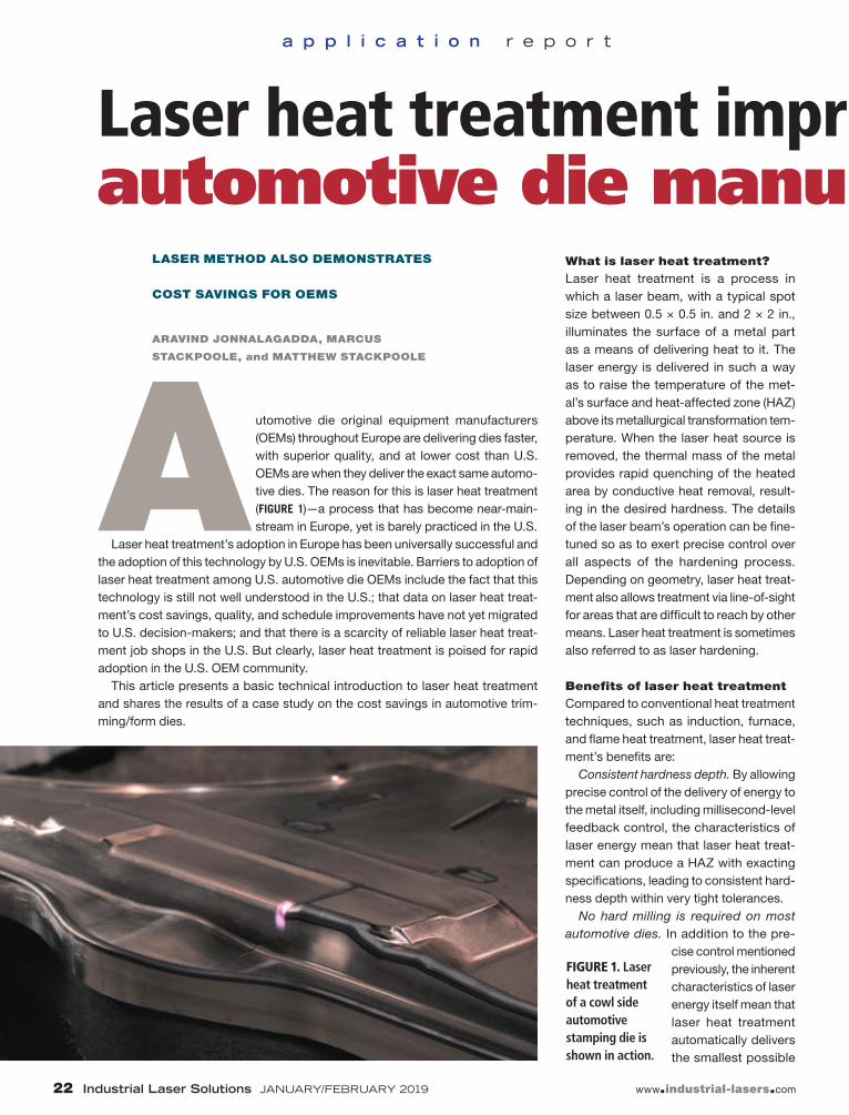
FIGURE 1. Laser heat treatment of a cowl side automotive stamping die is shown in action.
A utomotive die original equipment manufacturers (OEMs) throughout Europe are delivering dies faster, with superior quality, and at lower cost than U.S. OEMs are when they deliver the exact same automo-tive dies. The reason for this is laser heat treatment (FIGURE 1)—a process that has become near-main-stream in Europe, yet is barely practiced in the U.S.
Laser heat treatment’s adoption in Europe has been universally successful and the adoption of this technology by U.S. OEMs is inevitable. Barriers to adoption of laser heat treatment among U.S. automotive die OEMs include the fact that this technology is still not well understood in the U.S.; that data on laser heat treat-ment’s cost savings, quality, and schedule improvements have not yet migrated to U.S. decision-makers; and that there is a scarcity of reliable laser heat treat-ment job shops in the U.S. But clearly, laser heat treatment is poised for rapid adoption in the U.S. OEM community.
This article presents a basic technical introduction to laser heat treatment and shares the results of a case study on the cost savings in automotive trim-ming/form dies.
What is laser heat treatment?
Laser heat treatment is a process in which a laser beam, with a typical spot size between 0.5 × 0.5 in. and 2 × 2 in., illuminates the surface of a metal part as a means of delivering heat to it. The laser energy is delivered in such a way as to raise the temperature of the met-al’s surface and heat-affected zone (HAZ) above its metallurgical transformation tem-perature. When the laser heat source is removed, the thermal mass of the metal provides rapid quenching of the heated area by conductive heat removal, result-ing in the desired hardness. The details of the laser beam’s operation can be fine-tuned so as to exert precise control over all aspects of the hardening process. Depending on geometry, laser heat treat-ment also allows treatment via line-of-sight for areas that are difficult to reach by other means. Laser heat treatment is sometimes also referred to as laser hardening.
Benefits of laser heat treatment
Compared to conventional heat treatment techniques, such as induction, furnace, and flame heat treatment, laser heat treat-ment’s benefits are:
Consistent hardness depth. By allowing precise control of the delivery of energy to the metal itself, including millisecond-level feedback control, the characteristics of laser energy mean that laser heat treat-ment can produce a HAZ with exacting specifications, leading to consistent hard-ness depth within very tight tolerances.
No hard milling is required on most automotive dies. In addition to the pre-
cise control mentioned previously, the inherent characteristics of laser energy itself mean that laser heat treatment automatically delivers the smallest possible
Laser heat treatment improves quality in automotive die manufacturing
total energy to the die under treatment for any given HAZ size. This built-in fea-ture of the process automatically results in zero distortion in most automotive dies. Unlike conventional heat-treating meth-ods that require additional stock material to be milled after heat treatment, laser heat treatment is performed after the die is cut to final form. This results in cost savings from avoiding additional machining oper-ations while the material is hard.
Higher hardness. Due to rapid self-quenching of a heat-treated area in laser heat treatment, under the right pro-cess conditions, the typical hardness
achieved by the process tends to be a few points higher than flame or induction processes.
Precise application of beam energy to the work spot. Flames or coils need not be in close proximity to the work area, result-ing in greater ability to apply heat only to the intended area, with minimal to zero heating of adjoining areas.
Laser heat-treatable materials
Any steel with carbon content of 0.2% or greater is heat-treatable (FIGURE 2). In gen-eral, the hardness of the laser heat-treated dies is comparable to, or better than, the
FIGURE 2. A metallurgical cross-section of a laser heat-treated die in S7140 alloyed steel is shown.
hardness achieved by the use of conven-tional techniques.
A few of the common laser-treatable materials for automotive applications include:• D6510 ductile iron• S7140 alloyed steel • G2500 gray cast iron• G25HP gray cast iron• G3500 gray iron• D4512 ductile iron• S0030 non-alloyed steel• S0050A alloyed steel• A2 tool steel• D2 tool steel• S7 tool steel• M2 tool steel• 4140 alloy steel• 4340 alloy steel
Cost savings
Cost savings from laser heat treatment in the fabrication and maintenance of auto-motive dies results primarily from the elim-ination of post-hardening dimensional
restoration processes. To illustrate the potential for laser heat treatment, consider the following case study from the from one of the local OEM die suppliers.
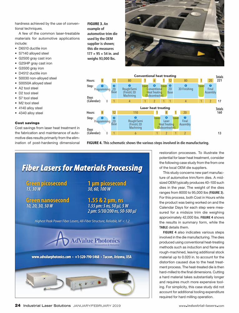
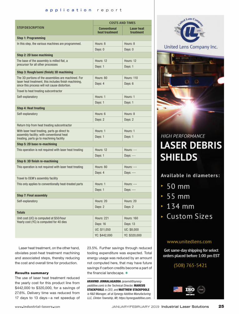
This study concerns new part manufac-ture of automotive trim/form dies. A mid-sized OEM typically produces 40–100 such dies in the year. The weight of the dies ranges from 8000 to 95,000 lbs (FIGURE 3). For this process, both Cost in Hours while the product was being worked on and the Calendar Days for each step were mea-sured for a midsize trim die weighing approximately 42,000 lbs. FIGURE 4 shows the results in summary form, while the TABLE details them.
FIGURE 4 also indicates various steps involved in the die manufacturing. The dies produced using conventional heat-treating methods such as induction and flame are rough-machined, leaving additional stock material up to 0.020 in. to account for the distortion caused due to the heat treat-ment process. The heat-treated die is then hard-milled to the final dimensions. Cutting a hard material takes substantially longer and requires much more expensive tool-ing. For simplicity, this case study did not account for additional tooling expenditure required for hard milling operation.
FIGURE 3. An example of automotive trim die used by the OEM supplier is shown; this die measures 177 × 95 × 54 in. and weighs 93,000 lbs.
FIGURE 4. This schematic shows the various steps involved in die manufacturing.
Laser heat treatment, on the other hand, obviates post-heat treatment machining and associated steps, thereby reducing the cost and overall time for production.
Results summary
The use of laser heat treatment reduced the yearly cost for this product line from $442,000 to $320,000, for a savings of 27.6%. Delivery time was reduced from 17 days to 13 days—a net speedup of
23.5%. Further savings through reduced tooling expenditure was expected. Total energy usage was reduced by an amount not computed here, that may have future savings if carbon credits become a part of the financial landscape. ✺
ARAVIND JONNALAGADDA ([email protected]) is the Technical Director, MARCUS STACKPOOLE is CEO, and MATTHEW STACKPOOLE is R&D Manager, all at Synergy Additive Manufacturing LLC, Clinton Township, MI; https://synergyadditive.com.
STEP/DESCRIPTIONCOSTS AND TIMES
Conventional heat treatment
Laser heat treatment
Step 1: Programming
In this step, the various machines are programmed. Hours: 8 Hours: 8
Days: 0 Days: 0
Step 2: 2D base machining
The base of the assembly is milled flat, a precursor for all other processes
Hours: 12 Hours: 12
Days: 1 Days: 1
Step 3: Rough/semi (finish) 3D machining
The 3D portions of the assemblies are machined. For laser heat treatment, this includes finish machining, since this process will not cause distortion.
Hours: 80 Hours: 110
Days: 4 Days: 6
Travel to heat treating subcontractor
Self-explanatory Hours: 1 Hours: 1
Days: 1 Days: 1
Step 4: Heat treating
Self-explanatory Hours: 6 Hours: 8
Days: 2 Days: 2
Return trip from heat treating subcontractor
With laser heat treating, parts go direct to assembly facility; with conventional heat treating, parts go to machining facility
Hours: 1 Hours: 1
Days: 1 Days: 1
Step 5: 2D base re-machining
This operation is not required with laser heat treating Hours: 12 Hours: ---
Days: 1 Days: ---
Step 6: 3D finish re-machining
This operation is not required with laser heat treating Hours: 80 Hours: ---
Days: 4 Days: ---
Travel to OEM’s assembly facility
This only applies to conventionally heat-treated parts Hours: 1 Hours: ---
Days: 1 Days: ---
Step 7: Final assembly
Self-explanatory Hours: 20 Hours: 20
Days: 2 Days: 2
Totals
Unit cost (UC) is computed at $50/hourYearly cost (YC) is computed for 40 dies
Extreme high-speed laser material deposition conquers industry PROCESS YIELDS INCREASED
SPEEDS AND LOWER COSTS OVER
CONVENTIONAL METHODS
THOMAS SCHOPPHOVEN, ANDRES
GASSER, AND GERHARD BACKES
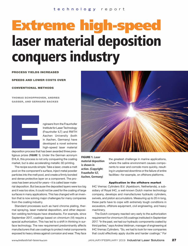
E ngineers from the Fraunhofer Institute for Laser Technology (Fraunhofer ILT) and RWTH Aachen University (both in Aachen, Germany) have developed a novel extreme high-speed laser material
deposition process that has been awarded three pres-tigious prizes (FIGURE 1). Under the German acronym EHLA, this process is not only conquering the coating market, but is also accelerating metallic 3D printing.
The recipe sounds simple: Take a laser, create a melt pool on the component’s surface, inject metal powder particles into the melt pool, and create a firmly bonded and dense protective layer on a component. The pro-cess has been around for years—it is called laser mate-rial deposition. But because the deposited layers were too big and it was too slow, it could not be used for the coating of large surfaces in many applications. This has changed with an inven-tion that is now solving major challenges for many companies from the coating industry.
Standard processes such as hard chrome plating, ther-mal spraying, laser material deposition, and other deposi-tion welding techniques have drawbacks. For example, since September 2017, coatings based on chromium (VI) require a special authorization. This has led to a shift in thinking in sur-face technology. The new requirement predominantly affects manufacturers that use coatings to protect metal components exposed to heavy stress against corrosion and wear. They face
the greatest challenge in marine applications, where the saline environment causes compo-nents to wear and corrode more quickly, result-ing in unplanned downtime or the failure of entire facilities—for example, on offshore platforms.
Application in the offshore market
IHC Vremac Cylinders B.V. (Apeldoorn, Netherlands), a sub-sidiary of Royal IHC, a well-known Dutch marine technology company, develops and manufactures hydraulic cylinders, swivels, and piston accumulators. Measuring up to 20 m long, these parts have to cope with extremely tough conditions in excavators, offshore equipment, civil engineering, and heavy machinery.
The Dutch company reacted very early to the authorization requirement for chromium (VI) coatings instituted in September 2017. “In the past, we had our hydraulic components coated by third parties,” says Andres Veldman, manager of engineering at IHC Vremac Cylinders. “So, we had to look for new companies that could effectively apply ductile and harder coatings.” For
FIGURE 1. Laser material deposition is shown in action. (Copyright: Fraunhofer ILT, Aachen, Germany)
applying ductile coatings, electrolytic techniques are a good choice, and for hard coatings, high-velocity oxygen fuel (HVOF) spraying is an option. But the experts in Apeldoorn also took a close look at laser processes.
However, initial testing in 2006 had shown that conventional laser material deposition was too expensive and too complicated. “But we were convinced that this technique was the future,” Veldman remembers. “In the end, it was in 2014 that Hornet Laser Cladding B.V. (Lexmond, Netherlands) put us in touch with Fraunhofer ILT and the ultra-fast EHLA process.”
IHC Vremac Cylinders opted to go with Fraunhofer ILT’s extreme high-speed laser material deposition pro-cess, which won the Joseph von Fraunhofer Prize in 2017, came second in the Steel in Research and Development category of the German steel industry federation’s Steel Innovation Award in 2018, and won the very prestigious Berthold Leibinger Innovationspreis in 2018. During the patented EHLA pro-cess, the powder particles are melted by the laser while they are still above the melt pool.
Coatings up to 500 m/min
The fact that the particles no longer need to melt in the melt pool means the processing speed can be increased from 0.5 to 2.0 m/min to as fast as 500 m/min. EHLA also makes it possible to reduce
the thickness of the coating—previously, it was not possible to produce coatings <500 µm thick at high deposition rates, but now, it can get them to be as thin as 25–250 µm. It also makes coat-ings smoother, with a surface roughness reduced to just one-tenth of what it typically was with con-ventional laser material deposition.
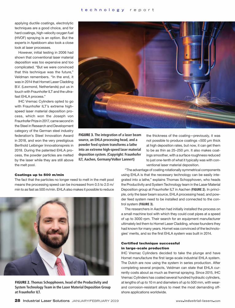
“The advantage of coating rotationally symmetrical components using EHLA is that the necessary technology can be easily inte-grated into a lathe,” explains Thomas Schopphoven, who heads the Productivity and System Technology team in the Laser Material Deposition group at Fraunhofer ILT in Aachen (FIGURE 2). In princi-ple, only the laser beam source, EHLA processing head, and pow-der feed system need to be installed and connected to the con-trol system (FIGURE 3).
The researchers in Aachen had initially installed the process on a small machine tool with which they could coat pipes at a speed of up to 3000 rpm. Their search for an equipment manufacturer ultimately led them to Hornet Laser Cladding, whose founders they had known for many years. Hornet was convinced of the technolo-gies’ merits, and so the first EHLA system was built in 2014.
Certified technique successful
in large-scale production
IHC Vremac Cylinders decided to take the plunge and have Hornet manufacture the first large-scale industrial EHLA system. The Dutch are now using the system in series production. After completing several projects, Veldman can state that EHLA cur-rently costs about as much as thermal spraying. Since 2015, IHC Vremac Cylinders has coated several hundred hydraulic cylinders, at lengths of up to 10 m and diameters of up to 500 mm, with wear- and corrosion-resistant alloys to meet the most demanding off-shore applications worldwide.
FIGURE 2. Thomas Schopphoven, head of the Productivity and System Technology Team in the Laser Material Deposition Group at Fraunhofer ILT.
FIGURE 3. The integration of a laser beam source, an EHLA processing head, and a powder feed system transforms a lathe into an extreme high-speed laser material deposition system. (Copyright: Fraunhofer ILT, Aachen, Germany/Volker Lannert)
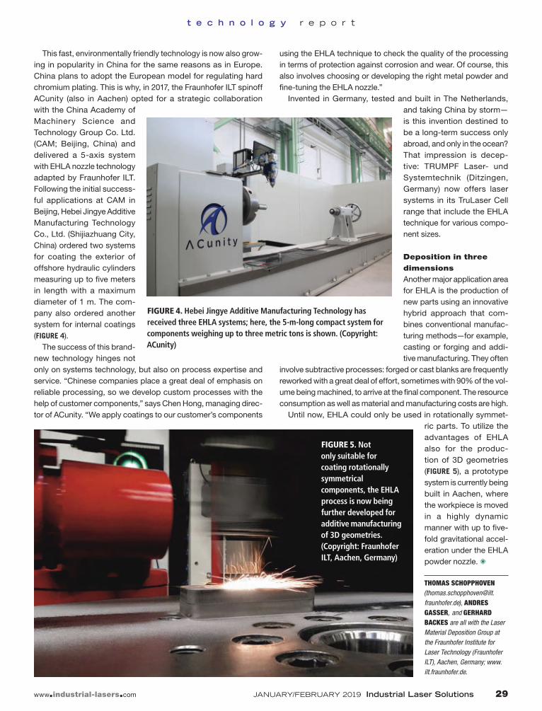
This fast, environmentally friendly technology is now also grow-ing in popularity in China for the same reasons as in Europe. China plans to adopt the European model for regulating hard chromium plating. This is why, in 2017, the Fraunhofer ILT spinoff ACunity (also in Aachen) opted for a strategic collaboration with the China Academy of Machinery Science and Technology Group Co. Ltd. (CAM; Beijing, China) and delivered a 5-axis system with EHLA nozzle technology adapted by Fraunhofer ILT. Following the initial success-ful applications at CAM in Beijing, Hebei Jingye Additive Manufacturing Technology Co., Ltd. (Shijiazhuang City, China) ordered two systems for coating the exterior of offshore hydraulic cylinders measuring up to five meters in length with a maximum diameter of 1 m. The com-pany also ordered another system for internal coatings (FIGURE 4).
The success of this brand-new technology hinges not only on systems technology, but also on process expertise and service. “Chinese companies place a great deal of emphasis on reliable processing, so we develop custom processes with the help of customer components,” says Chen Hong, managing direc-tor of ACunity. “We apply coatings to our customer’s components
using the EHLA technique to check the quality of the processing in terms of protection against corrosion and wear. Of course, this also involves choosing or developing the right metal powder and fine-tuning the EHLA nozzle.”
Invented in Germany, tested and built in The Netherlands, and taking China by storm—is this invention destined to be a long-term success only abroad, and only in the ocean? That impression is decep-tive: TRUMPF Laser- und Systemtechnik (Ditzingen, Germany) now offers laser systems in its TruLaser Cell range that include the EHLA technique for various compo-nent sizes.
Deposition in three
dimensions
Another major application area for EHLA is the production of new parts using an innovative hybrid approach that com-bines conventional manufac-turing methods—for example, casting or forging and addi-tive manufacturing. They often
involve subtractive processes: forged or cast blanks are frequently reworked with a great deal of effort, sometimes with 90% of the vol-ume being machined, to arrive at the final component. The resource consumption as well as material and manufacturing costs are high.
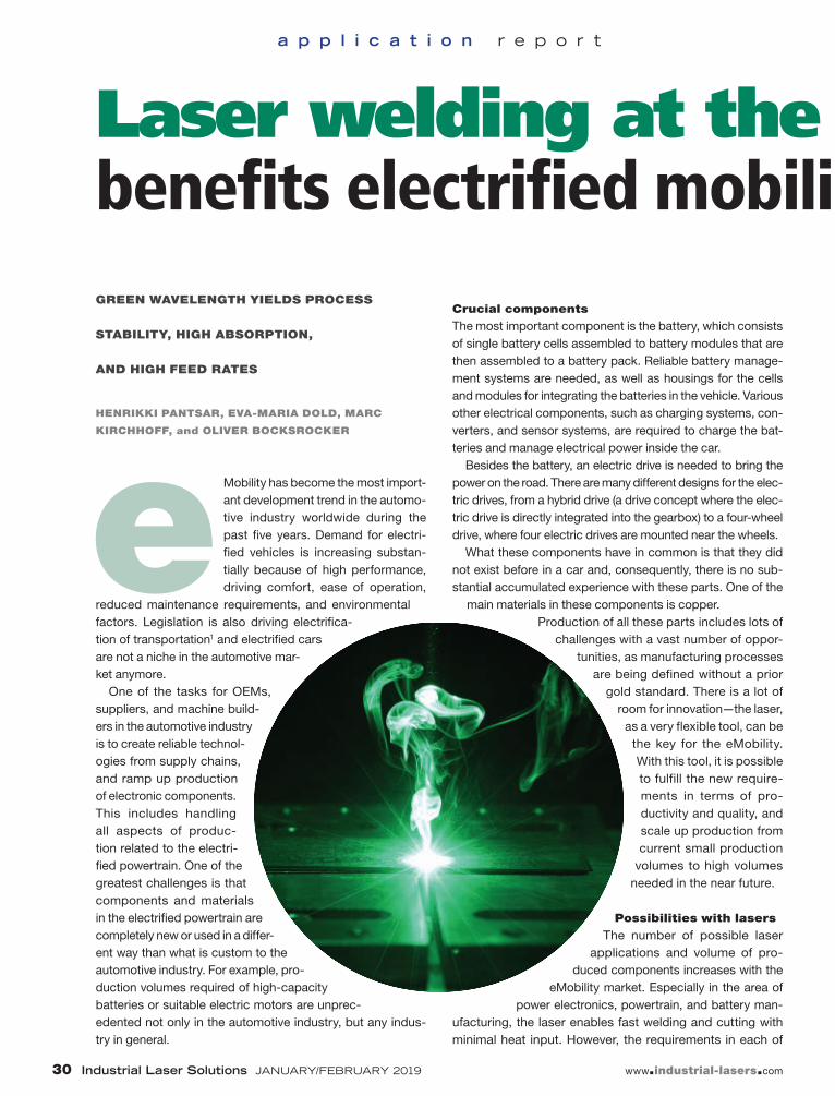
Until now, EHLA could only be used in rotationally symmet-ric parts. To utilize the advantages of EHLA also for the produc-tion of 3D geometries (FIGURE 5), a prototype system is currently being built in Aachen, where the workpiece is moved in a highly dynamic manner with up to five-fold gravitational accel-eration under the EHLA powder nozzle. ✺
THOMAS SCHOPPHOVEN ([email protected]), ANDRES GASSER, and GERHARD BACKES are all with the Laser Material Deposition Group at the Fraunhofer Institute for Laser Technology (Fraunhofer ILT), Aachen, Germany; www.ilt.fraunhofer.de.
FIGURE 4. Hebei Jingye Additive Manufacturing Technology has received three EHLA systems; here, the 5-m-long compact system for components weighing up to three metric tons is shown. (Copyright: ACunity)
FIGURE 5. Not only suitable for coating rotationally symmetrical components, the EHLA process is now being further developed for additive manufacturing of 3D geometries. (Copyright: Fraunhofer ILT, Aachen, Germany)
Laser welding at the green wavelength benefits electrified mobility applicationsGREEN WAVELENGTH YIELDS PROCESS
STABILITY, HIGH ABSORPTION,
AND HIGH FEED RATES
HENRIKKI PANTSAR, EVA-MARIA DOLD, MARC
KIRCHHOFF, and OLIVER BOCKSROCKER
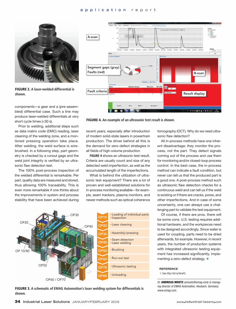
e Mobility has become the most import-ant development trend in the automo-tive industry worldwide during the past five years. Demand for electri-fied vehicles is increasing substan-tially because of high performance, driving comfort, ease of operation,
reduced maintenance requirements, and environmental factors. Legislation is also driving electrifica-tion of transportation1 and electrified cars are not a niche in the automotive mar-ket anymore.
One of the tasks for OEMs, suppliers, and machine build-ers in the automotive industry is to create reliable technol-ogies from supply chains, and ramp up production of electronic components. This includes handling all aspects of produc-tion related to the electri-fied powertrain. One of the greatest challenges is that components and materials in the electrified powertrain are completely new or used in a differ-ent way than what is custom to the automotive industry. For example, pro-duction volumes required of high-capacity batteries or suitable electric motors are unprec-edented not only in the automotive industry, but any indus-try in general.
Crucial components
The most important component is the battery, which consists of single battery cells assembled to battery modules that are then assembled to a battery pack. Reliable battery manage-ment systems are needed, as well as housings for the cells and modules for integrating the batteries in the vehicle. Various other electrical components, such as charging systems, con-verters, and sensor systems, are required to charge the bat-teries and manage electrical power inside the car.
Besides the battery, an electric drive is needed to bring the power on the road. There are many different designs for the elec-tric drives, from a hybrid drive (a drive concept where the elec-tric drive is directly integrated into the gearbox) to a four-wheel drive, where four electric drives are mounted near the wheels.
What these components have in common is that they did not exist before in a car and, consequently, there is no sub-stantial accumulated experience with these parts. One of the
main materials in these components is copper. Production of all these parts includes lots of
challenges with a vast number of oppor-tunities, as manufacturing processes
are being defined without a prior gold standard. There is a lot of
room for innovation—the laser, as a very flexible tool, can be
the key for the eMobility. With this tool, it is possible to fulfill the new require-ments in terms of pro-ductivity and quality, and scale up production from current small production
volumes to high volumes needed in the near future.
Possibilities with lasers
The number of possible laser applications and volume of pro-
duced components increases with the eMobility market. Especially in the area of
power electronics, powertrain, and battery man-ufacturing, the laser enables fast welding and cutting with minimal heat input. However, the requirements in each of
Laser welding at the green wavelength benefits electrified mobility applications
these areas differ significantly. Welding of electronic contacts on direct bonded copper (DBC) plates requires an exact weld-ing depth, minimal spatter, and heat input, as the surrounding components are very close to the welding position and would be destroyed if the process lacks stability. In the e-powertrain, the welding of hairpins requires high laser power and welding speed with minimal pores and spatters to generate good electrical properties. The same requirements are preconditioned in battery contacts, where accurate welding performance is a key factor for high quality and productivity. Again, most laser applications in these areas of eMobility components contain parts made of copper—the preferred domain for green-wavelength lasers (FIGURE 1).
The biggest advantage of copper, its high electrical and ther-mal conductivity, is also the biggest challenge for welding. Ten times higher heat conduction than in commonly used steels requires a very intense energy input. This could be solved with lasers, as this technology contributes high energy intensity on small interaction zones. However, similar material properties, which lead to high electrical conductivity, also lead to high reflectivity. Lasers deliver energy onto the workpiece in the form of light, typically in the near-infrared (near-IR) spectrum. Reflective met-als and most transparent materials typically absorb only a small frac-tion of IR laser light, which creates a challenge for IR lasers.
Only about 5% of the laser energy could be used for heating up the material in copper welding.2 High
intensity is needed to initiate the welding pro-cess and heat the material from room tempera-ture, where absorption of the laser light is low. The room-temperature copper surface reflects almost all the laser power to the surroundings, including optics. While this is very inefficient in terms of energy transfer, this could also damage sensitive parts. The absorption of the IR laser beam increases with the temperature up to more than 15% at melting temperature, but this transi-tion is hard to control.3 The process needs a high intensity to start, but with increasing absorption, the material could overheat. Therefore, heat con-duction welding is not well-reproducible. Deep penetration welding, on the other hand, suffers, especially at a low feed rate from weld defects —for example, melt ejections.4 And, because of
lower surface tension and viscosity of copper compared to steel, the melt pool is less stable.
Green laser capabilities, benefits
Absorption of the green laser (515 nm) to copper is 35–40%, so the welding process can be very stable without problems with initial absorption and overheating. Parameters are easy to find and process strategies such as wobbling are not needed. The green lasers by Trumpf are based on thin disk-laser technol-ogy and systems are ready for industrial use. The laser light is fiber-guided for easy integration into the machine.
It is possible to reproducibly weld even foils and small cop-per parts up to 0.4 mm in thickness in the heat conduction welding mode due to the good absorption of the green laser beam to copper. In the absence of the keyhole and result-ing melt dynamics, completely spatter-free copper welding with green lasers has been demonstrated (FIGURE 2). This was
FIGURE 2. Spatter-free copper welds made with green lasers exhibit very high quality and smooth weld surfaces.
FIGURE 1. Areas of green laser applications in eMobility are shown.
testified by high-speed video films in which one could see a perfectly smooth melt sur-face without motion. With comparable IR lasers, reproducible heat conduction weld-ing with copper is not possible because the absorption is temperature-depen-dent, and the process easily shifts from heat conduction welding to deep pene-tration welding. Depending on the weld-ing mode, copper foils are either not con-nected or destroyed.
Keeping the process temperature con-stantly between melting and evaporation temperature is not possible with IR laser beam welding. Because of process sta-bility and high absorption, high feed rates are possible with the green wavelength, which reduces heat loss from thermal con-duction and thermal expansion. Heat con-duction welding with green lasers is the first choice for battery foil welding and connect-ing small copper parts in electrical compo-nents (FIGURE 3).
For very heat-sensitive parts such as DBC plates or welding in heat-sensitive environments, it is recommended to use a microsecond-pulsed green laser. A
pulse mode offers more possibilities for thermal process management. The pulse pause effectively reduces thermal stress on the parts and the surrounding material. Gaps up to 0.1 mm are easy to handle by increasing the pulse overlap of the green laser. The material will cool down after each pulse and the thermal input can be reduced. In contrast to IR lasers, welding with a green laser beam does not pres-ent a problem with the interpulse cooling and following lack of temperature-depen-dent absorption.
Welding of thicker copper components for higher current flow is also possible (FIGURE 4). Copper with high surface qual-ity with thickness up to 0.8 mm is weldable. The maximum welding depth depends on the heat capacity of the part. Small parts or thinner sheets are easier to weld because the thermal conduction to the surrounding material is limited. This is a material issue and independent of the wavelength.
Absorption of an IR laser beam can be enhanced by surface coatings, oxidation, or other surface treatments.5 Coating of copper is not needed when using green wavelength lasers for welding. The absorp-tion phenomenon starts efficiently even at room temperature, regardless of the sur-face condition. Tests done with polished, sanded, acid-etched, and oxidized sur-faces show rather similar welding results. The green lasers show less affection on the surface condition (FIGURE 5). Oxidized or polished surfaces can be welded with the same parameters.
Conclusion
Copper welding has become one of the most important research topics in the
automotive industry because of eMobility. New techniques are needed to produce low-spatter, high-quality welds in copper. Using green wavelength lasers has proven to be a desired method for copper weld-ing. Instantaneous absorption onto a cop-per surface, in combination with a stable process, is a great advantage when weld-ing electrical components in batteries and electronics. Because of the lack of spat-ter, even pre-assembled electronic com-ponents can be welded without the risk of shorts. Industrial pulsed lasers with 400 W average power and 4 kW peak power are now available, as well as continuous-wave (CW) lasers up to 1 kW. Challenges of laser welding of copper have been overcome with this technology. ✺
REFERENCES
1. See https://bloom.bg/2Pn2YfK. 2. J. Bliedtner, H. Müller, and A. Barz,
Advanced manufacturing solutions for automotive powertrain productionPOST-PROCESS INSPECTION METHOD
ENABLES 100% TRACEABILITY
ANDREAS MOOTZ
A utomakers and their tiers are fac-ing big challenges. After decades of evolutionary development in the field of automotive pow-ertrains, electrification of vehi-cles creates enormous, disrup-tive changes.
At a glance, one could think that laser welding of traditional transmission and similar components (FIGURE 1) has no future. Most of the powertrain components, such as combustion engines and transmissions, will disappear and be replaced by electrical power units, batteries, and power electronics.
Is this really the future?
Various stakeholders try to predict the mar-ket share of different powertrain principles.
As an example, Schaeffler, one of Germany’s big automotive suppliers, pre-dicts a 30/40/30 scenario, saying that pure electric vehicles (EVs) will have a 30% mar-ket share by 2030, 40% will be hybrid vehi-cles (HEVs), and the traditional powertrain with one combustion engine will have a 30% market share.1
This creates new challenges, as electrical powertrain compo-nents bring a lot of additional weight into the car and need to be accelerated even when the car is using its combustion engine, thus creating more carbon dioxide (CO2) emissions as well as additional fuel cost. To avoid any cannibalization of the ecolog-ical advantages of electrical driving, big efforts are required to drive down vehicle weight, all under huge cost pressure since customers are facing already-big price tags for the batteries.
Joining in general and especially laser welding is an enabling technology to improve powertrain component weight and cost. FIGURE 2 shows a perfect example of this, where a massive gear is welded to the differential case instead of being bolted. This process was introduced 10 years ago for premium cars, making it a no-brainer for weight reduction and cost savings. Now, this technology is used for vehicles in all fields, from com-pact cars to heavy trucks as well as high-performance sports cars. This application is also a good example to demonstrate the requirements for a state-of-the-art manufacturing system.
FIGURE 3 shows the bill of process for the joining opera-tion to make a ready-for-assembly differential from individual
FIGURE 1. Typical laser-welded powertrain parts are shown.
components—a gear and a (pre-assem-bled) differential case. Such a line may produce laser-welded differentials at very short cycle times (<30 s).
Prior to welding, additional steps such as data matrix code (DMC) reading, laser cleaning of the welding zone, and a mon-itored pressing operation take place. After welding, the weld surface is wire-brushed. In a following step, part geom-etry is checked by a runout gage and the weld joint integrity is verified by an ultra-sonic flaw detection test.
The 100% post-process inspection of the welded differential is remarkable. Per part, quality data are measured and stored, thus allowing 100% traceability. This is even more remarkable if one thinks about the improvements in system and process stability that have been achieved during
recent years, especially after introduction of modern solid-state lasers in powertrain production. The driver behind all this is the demand for zero-defect strategies in all fields of high-volume production.
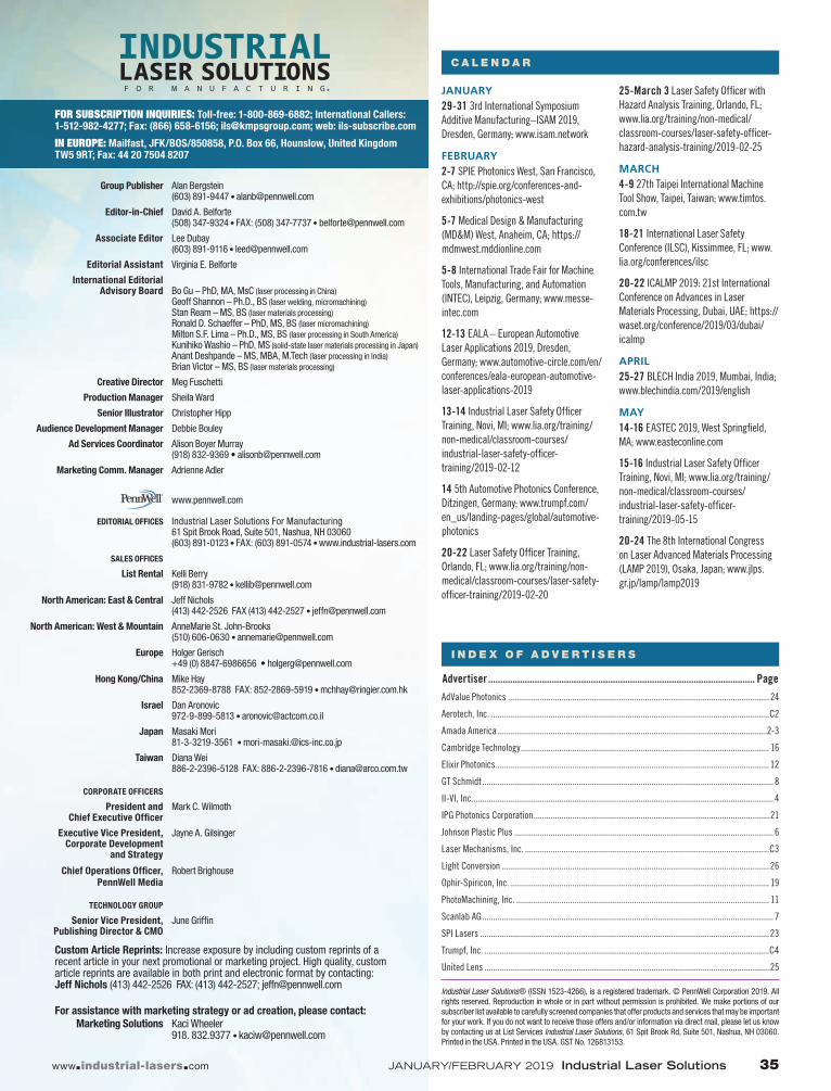
FIGURE 4 shows an ultrasonic test result. Criteria are usually count and size of any detected weld imperfection, as well as the accumulated length of the imperfections.
What is behind the utilization of ultra-sonic test equipment? There are a lot of proven and well-established solutions for in-process monitoring available—for exam-ple, seam trackers, plasma monitors, and newer methods such as optical coherence
tomography (OCT). Why do we need ultra-sonic flaw detection?
All in-process methods have one inher-ent disadvantage: they monitor the pro-cess, not the part. They detect signals coming out of the process and use them for monitoring and/or closed-loop process control. In the best case, the in-process method can indicate a fault condition, but never can tell us that the produced part is a good one. A post-process method such as ultrasonic flaw detection checks for a continuous weld and can tell us if the weld is existing or if there are cracks, pores, and other imperfections. And in case of some uncertainty, one can always use a chal-lenging part to validate the test equipment.
Of course, if there are pros, there will be some cons. U.S. testing requires addi-tional hardware, and the workpieces need to be designed accordingly. Since water is used for coupling, parts need to be dried afterwards, for example. However, in recent years, the number of production systems with integrated ultrasonic testing equip-ment has increased significantly, imple-menting a zero-defect strategy. ✺
REFERENCE
1. See http://bit.ly/ilsref2.
Dr. ANDREAS MOOTZ ([email protected]) is manag-ing director of EMAG Automation, Heubach, Germany; www.emag.com. FIGURE 3. A schematic of EMAG Automation’s laser welding system for differentials is
shown.
FIGURE 2. A laser-welded differential is shown.
FIGURE 4. An example of an ultrasonic test result is shown.
President and Mark C. Wilmoth Chief Executive Of� cer
Executive Vice President, Jayne A. Gilsinger Corporate Development and Strategy
Chief Operations Of� cer, Robert BrighousePennWell Media
TECHNOLOGY GROUP
Senior Vice President, June Grif� n Publishing Director & CMO
Custom Article Reprints: Increase exposure by including custom reprints of a recent article in your next promotional or marketing project. High quality, custom article reprints are available in both print and electronic format by contacting: Jeff Nichols (413) 442-2526 FAX: (413) 442-2527; [email protected]
For assistance with marketing strategy or ad creation, please contact: Marketing Solutions Kaci Wheeler 918. 832.9377 • [email protected]
II-VI, Inc. ............................................................................................................................................ 4
MARCH4-9 27th Taipei International Machine Tool Show, Taipei, Taiwan; www.timtos.com.tw
18-21 International Laser Safety Conference (ILSC), Kissimmee, FL; www.lia.org/conferences/ilsc
20-22 ICALMP 2019: 21st International Conference on Advances in Laser Materials Processing, Dubai, UAE; https://waset.org/conference/2019/03/dubai/icalmp
APRIL25-27 BLECH India 2019, Mumbai, India; www.blechindia.com/2019/english
MAY14-16 EASTEC 2019, West Spring� eld, MA; www.easteconline.com
This is the 34th year for publica-tion of Industrial Laser Solutions for Manufacturing, our for-mal name as the successor to Industrial Laser Review in
January 1999. Back in June 1986, we published the Annual Review of Industrial Laser Trends and Markets, offering the industrial laser community a look, for the first time globally, at their indus-try. It was minuscule then, showing total materials processing laser revenues at $114 million (system revenues at $274 million).
Maybe it was the small size of the 1986 indus-trial laser market (in today’s dollars, about $250 million) that did not attract market analysts, so ILShad it pretty much all to ourselves until total sales cracked the billion-dollar mark in 2002 ($1.3 billion in today’s dollars). Then, with a number of lead-ing suppliers that are public companies report-ing verifiable revenue data, competing analysts began to appear, offering laser market reports for sale online.
We were not very concerned about competing analysis in the early 2000s since they echoed the numbers ILS was publishing and we believed then, as we do now, that our unique definitive reports based on long-time views of the markets and its suppliers, plus the continuity of our reports, gave us an edge. That, plus ILS offered a value with our reports—they were freely distributed.
Since the last recession, when the industrial laser revenues charged out of the recession at a 15.2% CAGR clip, market analyst reports have multiplied each year, reaching more than 340 (and still counting) different reports on various seg-ments of the industrial laser and systems mar-ket in 2018.
I’m all for competition, but 340 reports on a $5 billion market—really? Okay, some of them cover industrial laser systems and that market is about $15 billion. But how much different can total numbers be? We all look at the same equipment supplier base.
That’s not what this My View column is about—it’s all about the data (developed for us by our sis-ter company Strategies Unlimited). And we think the use of ILS published data in others’ ‘for sale’ reports, without even a courteous credit of the source, is unprofessional, never mind unsanc-tioned. Data developed and presented in ILS is copyrighted and cannot be reproduced without permission, which we never do for public use, when it comes to our market reports.
So, after 34 years of freely sharing comprehen-sive data on the global industrial laser market, we have changed the format of the Annual Industrial Laser Market Review by reducing the details of data presented and supplementing it with textual material that should only be reproduced by copy-right permission (see page 9).
Now, on a lighter note, this issue starts a fresh editorial year for ILS, and we have put together issues packed with the latest on industrial laser material processing. I asked Prof. Dr. Thomas Graf to start 2019 with a look at what the future, in his view, looks like for industrial laser processing (see page 13). Many years ago, I did the same in another publication, advocating for an unlabeled black box producing usable photonic energy to weld, cut, etc.
I’ll be interested to hear readers’ views on Professor Graf’s outlook.