80
Edition 1.1 Controller series A CE1P2540en 12.12.2008 Building Technologies Heating Controllers RVL480 and RVL479 Basic Documentation
Edition 1.1 Controller series A CE1P2540en 12.12.2008 Building Technologies
Heating Controllers RVL480 and RVL479 Basic Documentation

2/80
Siemens Heating Controllers RVL480 and RVL479 CE1P2540en Building Technologies 12.12.2008
Siemens Switzerland Ltd Building Technologies Division International Headquarters Gubelstrasse 22 CH – 6301 Zug Tel. +41 41 724 24 24 Fax +41 41 724 35 22 www.sbt.siemens.com
c
3/80
Siemens Heating Controllers RVL480 and RVL479 CE1P2540en Building Technologies Contents 12.12.2008
Contents
1 Summary ........................................................................................................9
1.1 RVL480 and RVL479.......................................................................................9 1.2 Brief description and key features ...................................................................9 1.3 Equipment combinations .................................................................................9 1.3.1 Suitable sensors ..............................................................................................9 1.3.2 Suitable room units........................................................................................10 1.3.3 Suitable actuators..........................................................................................10 1.3.4 Communication..............................................................................................10 1.3.5 Passing on of heat demand signal ................................................................10 1.3.6 Product documentation..................................................................................10
2 Use ................................................................................................................11
2.1 Types of plant ................................................................................................11 2.2 Types of buildings..........................................................................................11 2.3 Types of heating systems..............................................................................11 2.4 Functions .......................................................................................................11
3 Fundamentals ..............................................................................................13
3.1 Key technical features ...................................................................................13 3.1.1 Plant types with regard to the heating circuit.................................................13 3.1.2 Function blocks..............................................................................................13 3.2 Plant types.....................................................................................................14 3.3 Plant types and function blocks .....................................................................16 3.4 Operating modes ...........................................................................................16 3.4.1 Automatic mode.............................................................................................16 3.4.2 Continuous REDUCED heating.....................................................................16 3.4.3 Continuous NORMAL heating .......................................................................16 3.4.4 Protection ......................................................................................................17 3.4.5 Manual operation...........................................................................................17 3.4.6 Plant type and operating mode......................................................................17 3.5 Operational status and operational level .......................................................17
4 Acquisition of measured values ................................................................18
4.1 Room temperature (A6, B5) ..........................................................................18 4.1.1 Measurement.................................................................................................18 4.1.2 Handling of faults...........................................................................................18 4.1.3 Room model ..................................................................................................18 4.2 Flow and boiler temperature (B1) ..................................................................18 4.2.1 Measurement.................................................................................................18 4.2.2 Handling of faults...........................................................................................19

4/80
Siemens Heating Controllers RVL480 and RVL479 CE1P2540en Building Technologies Contents 12.12.2008
4.3 Outside temperature (B9) ..............................................................................19 4.3.1 Measurement .................................................................................................19 4.3.2 Handling of faults ...........................................................................................19 4.4 Primary return temperature (B7) ....................................................................19 4.4.1 Measurement .................................................................................................19 4.4.2 Handling of faults ...........................................................................................20 4.5 Secondary return temperature (B71) .............................................................20 4.5.1 Measurement .................................................................................................20 4.5.2 Handling of faults ...........................................................................................20
5 Function block "End-user space heating" ................................................21
5.1 Operating lines...............................................................................................21 5.2 Setpoints ........................................................................................................21 5.2.1 General ..........................................................................................................21 5.2.2 Frost protection for the building .....................................................................21 5.3 Heating program ............................................................................................21 5.4 Holiday program.............................................................................................22
6 Function block "End-user general"............................................................23
6.1 Operating lines...............................................................................................23 6.2 Time of day and date .....................................................................................23 6.3 Indication of faults ..........................................................................................23
7 Function block "Plant type"........................................................................24
7.1 Operating line.................................................................................................24 7.2 General ..........................................................................................................24
8 Function block "Space heating".................................................................25
8.1 Operating lines...............................................................................................25 8.2 ECO function..................................................................................................25 8.2.1 Compensating variables and auxiliary variables............................................25 8.2.2 Heating limits .................................................................................................26 8.2.3 Mode of operation ..........................................................................................26 8.2.4 Operating modes and operational statuses ...................................................27 8.3 Room temperature source .............................................................................27 8.4 Optimization ...................................................................................................27 8.4.1 Definition and purpose ...................................................................................27 8.4.2 Fundamentals ................................................................................................27 8.4.3 Process ..........................................................................................................28 8.4.4 Room model temperature ..............................................................................28 8.4.5 Optimum stop control.....................................................................................29 8.4.6 Quick setback ................................................................................................29 8.4.7 Optimum start control.....................................................................................29
5/80
Siemens Heating Controllers RVL480 and RVL479 CE1P2540en Building Technologies Contents 12.12.2008
8.4.8 Boost heating.................................................................................................30 8.5 Room functions..............................................................................................31 8.5.1 Maximum limitation of the room temperature ................................................31 8.5.2 Room temperature influence .........................................................................31 8.6 Heating curve ................................................................................................32 8.6.1 Purpose .........................................................................................................32 8.6.2 Basic setting ..................................................................................................32 8.6.3 Deflection.......................................................................................................32 8.6.4 Parallel displacement of heating curve..........................................................33 8.6.5 Display of setpoints .......................................................................................33 8.7 Generation of setpoint ...................................................................................34 8.7.1 Weather-compensated control ......................................................................34 8.7.2 Demand-compensated control ......................................................................34
9 Function block "3-position actuator heating circuit"...............................35
9.1 Operating lines ..............................................................................................35 9.2 Limitations .....................................................................................................35 9.2.1 Limitations of the flow temperature................................................................35 9.2.2 Setpoint increase...........................................................................................35 9.3 3-position control ...........................................................................................36 9.4 Excess mixing valve temperature..................................................................36 9.5 Pulse lock ......................................................................................................36
10 Function block "Boiler" ..............................................................................37
10.1 Operating lines ..............................................................................................37 10.2 Operating mode.............................................................................................37 10.3 Limitations .....................................................................................................37 10.3.1 Maximum limitation of the boiler temperature................................................37 10.3.2 Minimum limitation of the boiler return temperature ......................................38 10.4 2-Position control...........................................................................................38 10.4.1 Control with a single-stage burner.................................................................38 10.4.2 Control with a 2-stage burner ........................................................................39 10.4.3 Frost protection for the boiler.........................................................................40 10.4.4 Protective boiler startup.................................................................................40 10.4.5 Protection against boiler overtemperatures...................................................41 10.5 Operating mode of pump M1.........................................................................42
11 Function block "Setpoint of return temperature limitation"....................43
11.1 Operating line ................................................................................................43 11.2 Description.....................................................................................................43 11.3 Minimum limitation of the return temperature ................................................43 11.3.1 Acquisition of the measured values...............................................................43 11.3.2 Mode of operation..........................................................................................43
6/80
Siemens Heating Controllers RVL480 and RVL479 CE1P2540en Building Technologies Contents 12.12.2008
11.3.3 Mode of operation with a single unit (with no bus).........................................44 11.3.4 Mode of operation in interconnected plants ...................................................44
12 Function block "District heat" ....................................................................45
12.1 Operating lines...............................................................................................45 12.2 Limitations......................................................................................................45 12.2.1 Secondary flow temperature ..........................................................................45 12.2.2 Maximum limitation of primary return temperature ........................................45 12.2.3 Maximum limitation of the return temperature differential (DRT limitation)....46 12.2.4 Integral action time.........................................................................................47 12.2.5 Minimum limitation of stroke (suppression of hydraulic creep) ......................47 12.2.6 Flow limitation ................................................................................................47
13 Function block "Service functions and general settings" .......................48
13.1 Operating lines...............................................................................................48 13.2 Display functions............................................................................................48 13.2.1 Flow temperature setpoint .............................................................................48 13.2.2 Heating curve.................................................................................................49 13.3 Commissioning aids.......................................................................................50 13.3.1 Simulation of outside temperature .................................................................50 13.3.2 Relay test .......................................................................................................50 13.3.3 Sensor test.....................................................................................................50 13.3.4 Test of H-contacts..........................................................................................51 13.4 Auxiliary functions ..........................................................................................52 13.4.1 Frost protection for the plant ..........................................................................52 13.4.2 Flow alarm .....................................................................................................52 13.4.3 Manual overriding of operating mode (contact H1)........................................53 13.4.4 Pump overrun ................................................................................................53 13.4.5 Pump kick ......................................................................................................54 13.4.6 Winter- / summertime changeover.................................................................54 13.4.7 Gain of locking signal.....................................................................................54 13.5 Entries for LPB...............................................................................................55 13.5.1 Source of time of day .....................................................................................55 13.5.2 Source of outside temperature.......................................................................56 13.5.3 Addressing of devices....................................................................................56 13.5.4 Bus power supply...........................................................................................57 13.5.5 Bus loading characteristic ..............................................................................57 13.6 Heat demand output DC 0...10 V...................................................................57
14 Function block "Contact H2" ......................................................................58
14.1 Operating line.................................................................................................58 14.2 Description .....................................................................................................58
15 Function block " Contact H2 and general displays" ................................59
7/80
Siemens Heating Controllers RVL480 and RVL479 CE1P2540en Building Technologies Contents 12.12.2008
15.1 Operating lines ..............................................................................................59 15.2 Contact H2.....................................................................................................59 15.3 Hours run counter..........................................................................................59 15.4 Software version............................................................................................59 15.5 Identification number of room unit .................................................................59
16 Function block "Locking functions"..........................................................60
16.1 Operating line ................................................................................................60 16.2 Locking the settings on the software side......................................................60 16.3 Locking the settings for district heat on the hardware side............................60
17 Communication ...........................................................................................61
17.1 Combination with room units .........................................................................61 17.1.1 General..........................................................................................................61 17.1.2 Combination with room unit QAW50 .............................................................61 17.1.3 Combination with room unit QAW70 .............................................................62 17.2 Combination with SYNERGYR central unit OZW30......................................64 17.3 Communication with other devices................................................................64
18 Heating controller RVL479..........................................................................65
18.1 Features and function....................................................................................65 18.2 Technical design............................................................................................65 18.2.1 Type of plant..................................................................................................65 18.2.2 Operation with a partner ................................................................................65 18.2.3 Handling errors ..............................................................................................66 18.2.4 Passive mode ................................................................................................66
19 Handling .......................................................................................................67
19.1 Operation.......................................................................................................67 19.1.1 General..........................................................................................................67 19.1.2 Analog operating elements............................................................................68 19.1.3 Digital operating elements .............................................................................68 19.1.4 Setting levels and access rights ....................................................................69 19.2 Commissioning ..............................................................................................70 19.2.1 Installation instructions ..................................................................................70 19.2.2 Operating lines ..............................................................................................70 19.3 Installation .....................................................................................................70 19.3.1 Location .........................................................................................................70 19.3.2 Mounting choices...........................................................................................70 19.3.3 Wiring ............................................................................................................71
20 Engineering..................................................................................................72
20.1 Connection terminals.....................................................................................72 20.1.1 Low voltage side............................................................................................72
8/80
Siemens Heating Controllers RVL480 and RVL479 CE1P2540en Building Technologies Contents 12.12.2008
20.1.2 Mains voltage side .........................................................................................72 20.2 Connection diagrams.....................................................................................73
21 Mechanical design .......................................................................................74
21.1 Basic design...................................................................................................74 21.2 Dimensions ....................................................................................................74
22 Technical data ..............................................................................................75
9/80
Siemens Heating Controllers RVL480 and RVL479 CE1P2540en Building Technologies 1 Summary 12.12.2008
1 Summary
1.1 RVL480 and RVL479
This Basic Documentation covers two types of heating controllers, the RVL480 and the RVL479. The RVL480 is described in every detail, not so the RVL479. The RVL479 contains functions of the RVL480 and is therefore integrated in the pre-sent Basic Documentation. But only the chapter “18 Heating controller RVL479” refers to the specific functionality of the RVL479 (functions that differ from those of the RVL480). In all the other chapters and sections, the RVL479 will not be specifically mentioned.
1.2 Brief description and key features
• The RVL480 is a multi-functional heating controller for use in residential and non-residential buildings. It is suited for weather-compensated flow temperature control of heating zones with or without room temperature influence or for demand-compen-sated control of heat generating equipment (precontrol)
• It is used in plants with own heat generating equipment or with a district heat con-nection
• The RVL480 is capable of communicating with other units via LPB (Local Process Bus)
• The RVL480 has 6 types of plants pre-programmed. When a certain plant type is selected, all functions and settings required for that particular plant will be activated
• For the direct setting of the heating curve, the proven bar is used, but digital adjust-ment of the heating curve is also possible. For readjustment of the room tempera-ture, a setting knob is used
• A scalable voltage output DC 0…10 V is used to pass the heat demand signal to other systems
• All other parameters are set digitally using the operating line principle • Operating voltage AC 230 V, CE conformity, overall dimensions to IEC 61554
(144 × 144 mm)
1.3 Equipment combinations
1.3.1 Suitable sensors
• For water temperatures: Suitable are all types of temperature sensors that use a sensing element LG-Ni 1000. The following types are presently available: − Clamp-on temperature sensor QAD22 − Immersion temperature sensor QAE212… − Immersion temperature sensor QAP21.3 with integrated connecting cable
• For the room temperature: Suitable are all types of temperature sensors that use a sensing element LG-Ni 1000. − Room temperature sensor QAA24
• For the outside temperature: − Outside sensor QAC22 (sensing element LG-Ni 1000) − Outside sensor QAC32 (sensing element NTC 575)
10/80
Siemens Heating Controllers RVL480 and RVL479 CE1P2540en Building Technologies 1 Summary 12.12.2008
1.3.2 Suitable room units
• Room unit QAW50 • Room unit QAW70
1.3.3 Suitable actuators
All Siemens actuators with the following features can be used: • Electric or electro-hydraulic actuators with a running time of 0.5 to 14.5 minutes • Suitable for 3-position control • Operating voltage AC 24 V … AC 230 V
1.3.4 Communication
Communication is possible with the following types of units: • All controllers made by Siemens with LPB communication capability • SYNERGYR central unit OZW30 (software version 3.0 or higher)
The heating controller RVL480 cannot be used as partner unit for the RVL469!
1.3.5 Passing on of heat demand signal
The scalable DC 0…10 V signal can be used to pass the heat demand signal to other devices in the system.
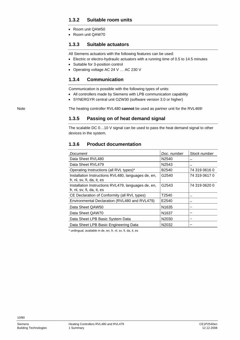
1.3.6 Product documentation
Document Doc. number Stock number Data Sheet RVL480 N2540 – Data Sheet RVL479 N2543 – Operating Instructions (all RVL types)* B2540 74 319 0616 0 Installation Instructions RVL480, languages de, en, fr, nl, sv, fi, da, it, es
G2540 74 319 0617 0
Installation Instructions RVL479, languages de, en, fr, nl, sv, fi, da, it, es
G2543 74 319 0620 0
CE Declaration of Conformity (all RVL types) T2540 – Environmental Declaration (RVL480 and RVL479) E2540 – Data Sheet QAW50 N1635 – Data Sheet QAW70 N1637 – Data Sheet LPB Basic System Data N2030 – Data Sheet LPB Basic Engineering Data N2032 –
* unilingual, available in de, en, fr, nl, sv, fi, da, it, es
Note
11/80
Siemens Heating Controllers RVL480 and RVL479 CE1P2540en Building Technologies 2 Use 12.12.2008
2 Use
2.1 Types of plant
Basically, the RVL480 is suitable for all types of heating plants that use weather-compensated flow temperature control. In addition, it can be used for demand-compensated control of the main flow. Examples: • Heating zones with own heat generation • Heating zones with a direct or indirect district heat connection • Main groups with own heat generation • Main groups with a direct or indirect district heat connection • Large plants comprising heat generation and several heating zones
2.2 Types of buildings
Basically, the RVL480 is suitable for all types of buildings that use weather-compensated heating control, but is designed specifically for use in: • Multi-family houses • Single-family houses • Non-residential buildings
2.3 Types of heating systems
The RVL480 is suitable for use with all standard heating systems, such as: • Radiators • Convectors • Underfloor heating systems • Ceiling heating systems • Radiant panels
2.4 Functions
The RVL480 is used if one or several of the following functions is / are required: • Weather-compensated flow temperature control • Flow temperature control through a modulating seat or slipper valve, or boiler tem-
perature control through direct control of a single- or 2-stage burner • Optimum start / stop control according to the selected weekly program • Quick setback and boost heating according to the selected weekly program • ECO function: demand-dependent switching of the heating system based on the type
of building construction and the outside temperature • Weekly program for building occupancy with a maximum of three setback periods
per day and daily varying occupancy schedules • Voltage output DC 0…10 V for passing on the heat demand signal • Entry of eight holiday periods per year • Automatic summer-/wintertime changeover • Display of parameters, actual values, operational statuses and fault status signals • Communication with other units via the LPB • Remote operation with the help of a room unit and external switches • Service functions • Frost protection for the plant, the boiler and the building • Minimum or maximum limitation of return temperature • DRT limitation (limitation of the temperature differential) • Minimum and maximum limitation of flow temperature
12/80
Siemens Heating Controllers RVL480 and RVL479 CE1P2540en Building Technologies 2 Use 12.12.2008
• Maximum limitation of room temperature • Periodic pump run • Pump overrun • Maximum limitation of the rate of setpoint increase • Flow alarm For application examples, refer to chapter "3. Fundamentals".

13/80
Siemens Heating Controllers RVL480 and RVL479 CE1P2540en Building Technologies 3 Fundamentals 12.12.2008
3 Fundamentals
3.1 Key technical features
The RVL480 offers two key technical features: • The controller has six plant types preprogrammed • The settings are combined in the form of function blocks
3.1.1 Plant types with regard to the heating circuit
In terms of the heating circuit, the following plant types are available: • Plant type 1 – "Heating circuit control with mixing group" • Plant type 2 – "Heating circuit control with boiler " • Plant type 3 – "Heating circuit control with heat exchanger" • Plant type 4 – "Precontrol with mixing group, heat demand signal via data bus” • Plant type 5 – "Precontrol with boiler, heat demand signal via data bus” • Plant type 6 – "Precontrol with heat exchanger, heat demand signal via data bus”
3.1.2 Function blocks
The following function blocks are available: • Function block "End-user 1" • Function block "End-user 2" • Function block "Plant type" • Function block "Space heating" • Function block "Three-position actuator for heating circuit" • Function block "Boiler" • Function block "Setpoint of return temperature limitation" • Function block "Settings for plant type 3" • Function block "Service functions and general settings" • Function block "Contact H2" • Function block "Contact H2 and general displays" • Function block “Locking functions” For each function block, the required settings are available in the form of operating lines. A description of the individual functions is given below, for each function block and line.
14/80
Siemens Heating Controllers RVL480 and RVL479 CE1P2540en Building Technologies 3 Fundamentals 12.12.2008
3.2 Plant types
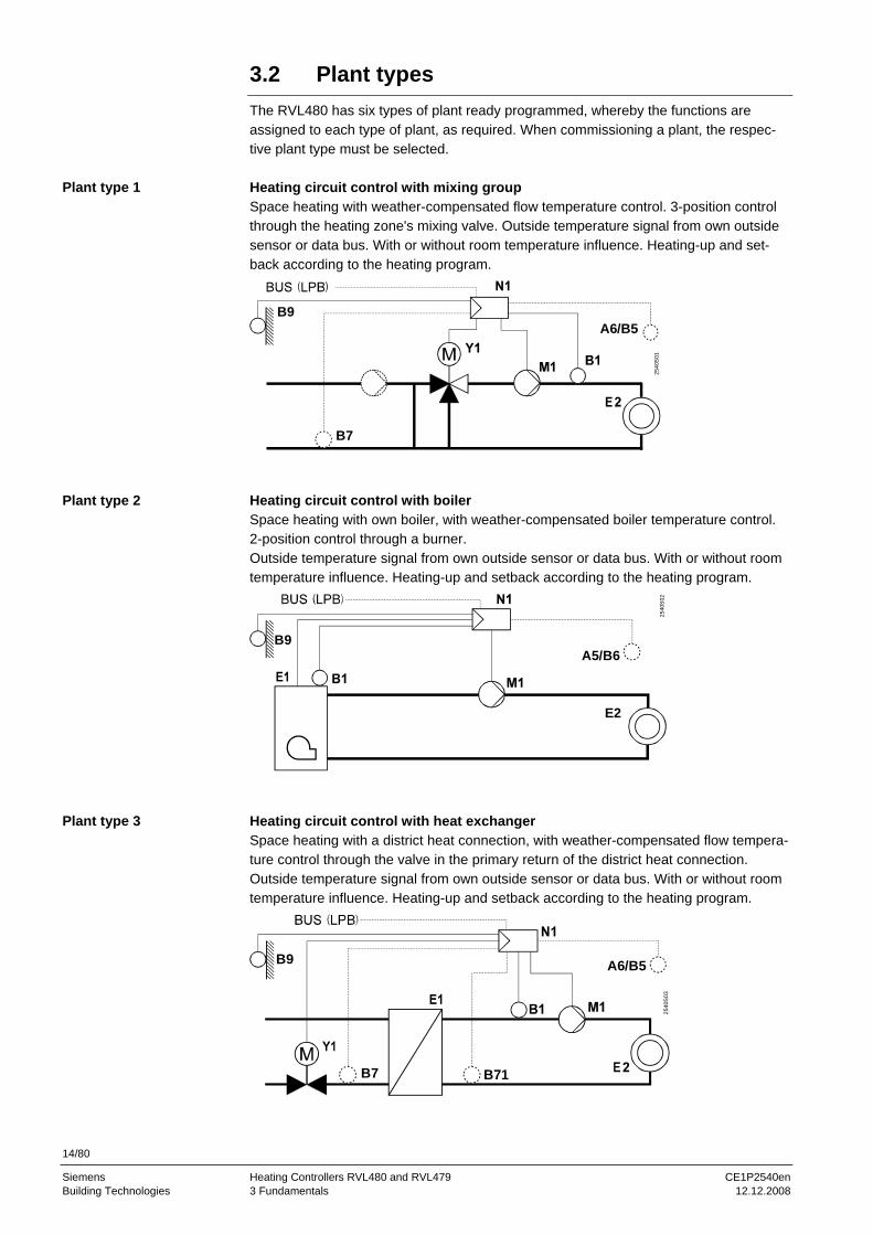
The RVL480 has six types of plant ready programmed, whereby the functions are assigned to each type of plant, as required. When commissioning a plant, the respec-tive plant type must be selected. Heating circuit control with mixing group Space heating with weather-compensated flow temperature control. 3-position control through the heating zone's mixing valve. Outside temperature signal from own outside sensor or data bus. With or without room temperature influence. Heating-up and set-back according to the heating program.
B9A6/B5
B7
2540
S01
Heating circuit control with boiler Space heating with own boiler, with weather-compensated boiler temperature control. 2-position control through a burner. Outside temperature signal from own outside sensor or data bus. With or without room temperature influence. Heating-up and setback according to the heating program.
A5/B6B9
E2
2540
S02
Heating circuit control with heat exchanger Space heating with a district heat connection, with weather-compensated flow tempera-ture control through the valve in the primary return of the district heat connection. Outside temperature signal from own outside sensor or data bus. With or without room temperature influence. Heating-up and setback according to the heating program.
B9 A6/B5
B7 B71
2540
S03
Plant type 1
Plant type 2
Plant type 3
15/80
Siemens Heating Controllers RVL480 and RVL479 CE1P2540en Building Technologies 3 Fundamentals 12.12.2008
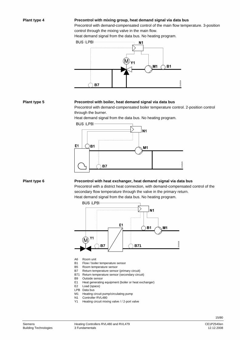
Precontrol with mixing group, heat demand signal via data bus Precontrol with demand-compensated control of the main flow temperature. 3-position control through the mixing valve in the main flow. Heat demand signal from the data bus. No heating program.
B7 2540
S04
Precontrol with boiler, heat demand signal via data bus Precontrol with demand-compensated boiler temperature control. 2-position control through the burner. Heat demand signal from the data bus. No heating program.
B7 2540
S05
Precontrol with heat exchanger, heat demand signal via data bus Precontrol with a district heat connection, with demand-compensated control of the secondary flow temperature through the valve in the primary return. Heat demand signal from the data bus. No heating program.
B7 B71 2540
S06
A6 Room unit B1 Flow / boiler temperature sensor B5 Room temperature sensor B7 Return temperature sensor (primary circuit) B71 Return temperature sensor (secondary circuit) B9 Outside sensor E1 Heat generating equipment (boiler or heat exchanger) E2 Load (space) LPB Data bus M1 Heating circuit pump/circulating pump N1 Controller RVL480 Y1 Heating circuit mixing valve / / 2-port valve
Plant type 4
Plant type 5
Plant type 6
16/80
Siemens Heating Controllers RVL480 and RVL479 CE1P2540en Building Technologies 3 Fundamentals 12.12.2008
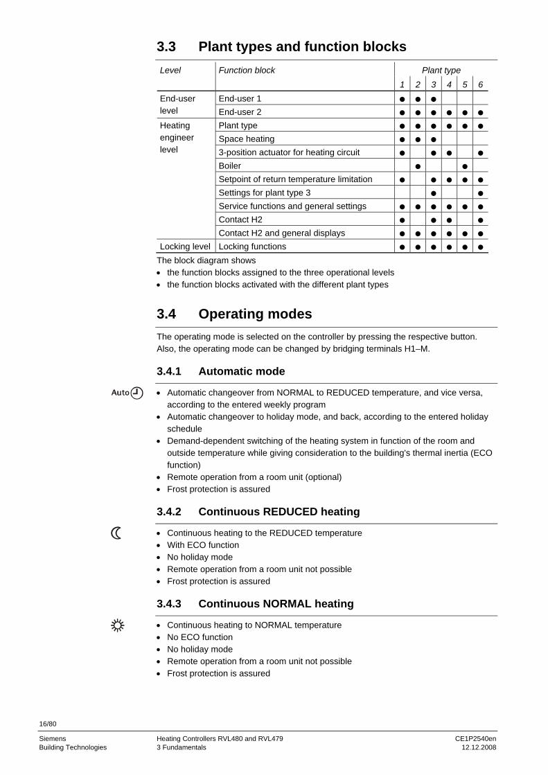
3.3 Plant types and function blocks
Plant type Level Function block 1 2 3 4 5 6
End-user 1 End-user level End-user 2
Plant type Space heating 3-position actuator for heating circuit Boiler Setpoint of return temperature limitation Settings for plant type 3 Service functions and general settings Contact H2
Heating engineer level
Contact H2 and general displays Locking level Locking functions
The block diagram shows • the function blocks assigned to the three operational levels • the function blocks activated with the different plant types
3.4 Operating modes
The operating mode is selected on the controller by pressing the respective button. Also, the operating mode can be changed by bridging terminals H1–M.
3.4.1 Automatic mode
• Automatic changeover from NORMAL to REDUCED temperature, and vice versa, according to the entered weekly program
• Automatic changeover to holiday mode, and back, according to the entered holiday schedule
• Demand-dependent switching of the heating system in function of the room and outside temperature while giving consideration to the building's thermal inertia (ECO function)
• Remote operation from a room unit (optional) • Frost protection is assured
3.4.2 Continuous REDUCED heating
• Continuous heating to the REDUCED temperature • With ECO function • No holiday mode • Remote operation from a room unit not possible • Frost protection is assured
3.4.3 Continuous NORMAL heating
• Continuous heating to NORMAL temperature • No ECO function • No holiday mode • Remote operation from a room unit not possible • Frost protection is assured

17/80
Siemens Heating Controllers RVL480 and RVL479 CE1P2540en Building Technologies 3 Fundamentals 12.12.2008
3.4.4 Protection
• Heating is switched off, but is ready to operate • Frost protection is assured
3.4.5 Manual operation
The RVL480 can be switched to manual operation. In that case, the control will be switched off. In manual operation, the various regulating units behave as follows: • Heating circuit mixing valve: it is not under voltage, but can be manually driven to
any position by pressing the manual buttons / (close) and / (open). The heating circuit pump/circulating pump M1 is continuously running.
• Boiler: the two burner stages are continuously on. The manual button / can be used to switch the second stage on and off. The heating circuit pump/circulating pump M1 is continuously running.
Manual operation also negates any overriding of the controller's operating mode (bridg-ing H1–M).
3.4.6 Plant type and operating mode
Depending on the type of plant selected, the following operating modes are available:
Plant type 1 YES YES YES YES YES 2 YES YES YES YES YES 3 YES YES YES YES YES 4 YES NO NO NO YES 5 YES NO NO * YES 6 YES NO NO NO YES
* Depending on the boiler's operating mode: Boiler with automatic shutdown: NO Boiler without manual shutdown: YES
3.5 Operational status and operational level
The user selects the required operating mode by pressing the respective button. Each operating mode has a maximum of two operational statuses – with the exception of operating mode "Continuously NORMAL heating" (only one operational status possi-ble). When the ECO function is activated and in the case of quick setback, the opera-tional status is always OFF. When the operational status is ON, there is a maximum of three operational levels, depending on the operating mode. The operational level is determined by the heating program and the holiday program.
2540
Z08
OFF ON ON ON ONOFF OFF
Operating mode
Operating state
Operational level

18/80
Siemens Heating Controllers RVL480 and RVL479 CE1P2540en Building Technologies 4 Acquisition of measured values 12.12.2008
4 Acquisition of measured values
4.1 Room temperature (A6, B5)
4.1.1 Measurement
The following choices exist: • A room temperature sensor QAA24 can be connected to terminal B5 • A room unit QAW50 or QAW70 can be connected to terminal A6 • A unit can be connected to each of the two terminals. In that case, the RVL480 can
ascertain the average of the two measurements. The other room unit functions will not be affected by averaging
4.1.2 Handling of faults
If there is a short-circuit or an interruption in one of the two measuring circuits, the control will respond as follows: • No sensor (operating line 65 = 0):
A short-circuit or open-circuit has no impact on the control. A fault status message will not be generated
• Room unit sensor QAW… (operating line 65 = 1): In the event of a short-circuit or open-circuit, the control continues to operate de-pending on the function of the room model. A fault status message will be generated
• Room temperature sensor QAA24 (operating line 65 = 2): In the event of a short-circuit or open-circuit, the control continues to operate de-pending on the function of the room model. A fault status message will be generated
• Average value (operating line 65 = 3): In the event of a short-circuit or open-circuit in one of the two measuring circuits, the control continues to operate with the normally working measuring circuit. A fault sta-tus message will be generated. In the case of a short-circuit or open-circuit in both measuring circuits, the control continues to operate depending on the function of the room model. Two fault status messages will be generated
• Automatic mode (operating line 65 = A): Since the controller itself decides how it acquires the room temperature, no fault sta-tus messages can be generated
4.1.3 Room model
The RVL480 features a room model which simulates the development of the room temperature. In plants with no measurement of the room temperature, it can provide certain room functions (e.g. quick setback). For more details, refer to section "8.4.4 Room model temperature".
4.2 Flow and boiler temperature (B1)
4.2.1 Measurement
The flow or boiler temperature is acquired with one sensor having a sensing element LG-Ni 1000. Averaging is not possible.
19/80
Siemens Heating Controllers RVL480 and RVL479 CE1P2540en Building Technologies 4 Acquisition of measured values 12.12.2008
4.2.2 Handling of faults
A short-circuit or interruption in the measuring circuit is identified and displayed as a fault. In that case, the plant will respond as follows: • Plants with mixing valve control:
The heating circuit pump/circulating pump M1 continues to run and the mixing valve will close
• Plants with boiler control: The heating circuit pump/circulating pump M1 continues to run and the burner will shut down
4.3 Outside temperature (B9)
4.3.1 Measurement
The outside temperature is acquired by the outside sensor, which may be a QAC22 or QAC32: • QAC22: sensing element LG-Ni 1000 • QAC32: sensing element NTC 575 The controller automatically identifies the type of sensor used. In interconnected plants, the outside temperature signal is made available via LPB. Controllers having their own sensor pass the outside temperature signal to the data bus.
4.3.2 Handling of faults
If there is a short-circuit or an interruption in the measuring circuit, the control will re-spond as follows: • In the event of a short-circuit:
If an outside temperature is made available via LPB, it is used. If none is available, the control uses a fixed value of 0 °C outside temperature. A fault status signal is al-ways generated
• In the event of an interruption: If the controller requires an outside temperature and it is made available via LPB, it is used. There will be no fault status signal in that case (this is the usual status in inter-connected plants!). If, however, there is no outside temperature made available via LPB, the control uses a fixed value of 0 °C. In that case, a fault status signal will be delivered
4.4 Primary return temperature (B7)
4.4.1 Measurement
The primary return temperature is acquired with a sensor having a sensing element LG-Ni 1000. This measured value is required for minimum and maximum limitation of the primary return temperature and for limitation of the temperature differential (DRT limitation). In interconnected plants, the primary return temperature with plant type 1 can be ac-quired via the data bus. Controllers with plant type 1 and connected sensor pass the primary return temperature signal to the data bus.

20/80
Siemens Heating Controllers RVL480 and RVL479 CE1P2540en Building Technologies 4 Acquisition of measured values 12.12.2008
4.4.2 Handling of faults
If there is a short-circuit or an interruption in the measuring circuits, the control will respond as follows: • If, on the data bus, there is a return temperature from a controller of the same seg-
ment available, it is used (only with plant type no. 1). No fault status message will be generated since this is the normal status in interconnected plants
• If, on the data bus, there is no return temperature available, the return temperature limitation functions will be deactivated and a fault status message generated
4.5 Secondary return temperature (B71)
4.5.1 Measurement
The secondary return temperature is acquired with a sensor having a sensing element LG-Ni 1000. This measured value is required for limitation of the temperature differen-tial (DRT limitation; plant types 3 and 6), together with the primary return temperature.
4.5.2 Handling of faults
If there is a short-circuit or open-circuit in the measuring circuit, and if the controller requires the return temperature, DRT limitation will be deactivated and a fault status message generated.

21/80
Siemens Heating Controllers RVL480 and RVL479 CE1P2540en Building Technologies 5 Function block "End-user space heating" 12.12.2008
5 Function block "End-user space heating"
This function block contains settings that the end-user himself can make.
5.1 Operating lines
Line Function, parameter Factory setting (range) Unit 1 Setpoint for NORMAL heating 20.0 (0…35) °C 2 Setpoint for REDUCED heating 14.0 (0…35) °C 3 Setpoint for frost protection / holiday mode 10.0 (0…35) °C 4 Weekday 1-7 (1…7 / 1-7) 5 First heating period, start of NORMAL heating 06:00 (00:00…24:00) hh:mm6 First heating period, start of REDUCED heating 22:00 (00:00…24:00) hh:mm7 Second heating period, start of NORMAL heating --:-- (00:00…24:00) hh:mm8 Second heating period, start of REDUCED heating --:-- (00:00…24:00) hh:mm9 Third heating period, start of NORMAL heating --:-- (00:00…24:00) hh:mm
10 Third heating period, start of REDUCED heating --:-- (00:00…24:00) hh:mm11 Holiday period 1…8 - (1…8) 12 Date of first day of holidays --.-- (01.01…31.12) dd:MM13 Date of last day of holidays --.-- (01.01…31.12) dd:MM14 Heating curve, flow setpoint at 15 °C outside temperature 30 (20…70) °C 15 Heating curve, flow setpoint at –5 °C outside temperature 60 (20…120) °C
5.2 Setpoints
5.2.1 General
The setpoint of the NORMAL and the REDUCED temperature and of frost protection for the plant / holiday mode are entered directly in °C room temperature. They are inde-pendent of whether or not the control uses a room temperature sensor.
5.2.2 Frost protection for the building
The lowest valid room temperature setpoint always corresponds to at least the setpoint of frost protection / holiday mode (setting on operating line 3), even if lower values have been entered as the setpoints of the NORMAL and the REDUCED temperature (set-tings on operating lines 1 and 2). If a room temperature sensor is used and the room temperature falls below the holiday / frost protection setpoint, ECO – if available – will stop OFF until the room temperature has risen 1 °C above the holiday / frost protection setpoint.
5.3 Heating program
The heating program of the RVL480 provides a maximum of three heating periods per day. Also, every weekday may have different heating periods.
The entries to be made are not switching times, but periods of time during which the NORMAL temperature shall apply. Usually, these periods of time are identical to the building's occupancy times. The actual switching times for the change from the REDUCED to the NORMAL temperature, and vice versa, are calculated by the optimi-zation function, provided it is activated.
Using the setting "1-7" on operating line 4, it is possible to enter a heating program that applies to all days of the week. This simplifies the settings: if the weekend settings differ from the other weekday settings, first enter the times for the entire week, then make the settings for days 6 and 7. The entries are sorted and overlapping heating periods combined.
Note
22/80
Siemens Heating Controllers RVL480 and RVL479 CE1P2540en Building Technologies 5 Function block "End-user space heating" 12.12.2008
5.4 Holiday program
A maximum of eight holiday periods per year can be programmed. At 00:00 of the first day of the holiday period, changeover to the setpoint of frost protection / holiday mode takes place. After 24:00 of the last day of the holiday period, the RVL480 will change to NORMAL or REDUCED mode in accordance with the time switch settings. The settings of each holiday period will be cleared as soon as the respective period has elapsed. The holiday periods may overlap. It is not necessary to observe a certain order. The holiday program is only activated in AUTO mode.
23/80
Siemens Heating Controllers RVL480 and RVL479 CE1P2540en Building Technologies 6 Function block "End-user general" 12.12.2008
6 Function block "End-user general"
This function block contains settings that the end-user himself may make, as well as fault indication.
6.1 Operating lines
Line Function, parameter Factory setting (range) Unit 38 Time of day 00:00…23:59 hh:mm 39 Weekday Display function 40 Date (01.01…31.12) dd:MM 41 Year (1995…2094) jjjj 50 Faults Display function
6.2 Time of day and date
The RVL480 has a yearly clock to enter the time of day and the date. The weekday on line 39 is set automatically with the date and cannot be adjusted. The changeover from summer- to wintertime, and vice versa, is automatic. Should the respective regulations change, the changeover dates can be adjusted (refer to chapter "13 Function block "Service functions and general settings"").
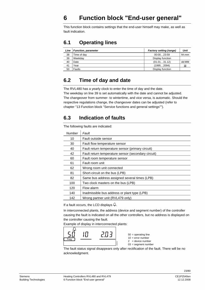
6.3 Indication of faults
The following faults are indicated:
Number Fault 10 Fault outside sensor 30 Fault flow temperature sensor 40 Fault return temperature sensor (primary circuit) 42 Fault return temperature sensor (secondary circuit) 60 Fault room temperature sensor 61 Fault room unit 62 Wrong room unit connected 81 Short-circuit on the bus (LPB) 82 Same bus address assigned several times (LPB)
100 Two clock masters on the bus (LPB) 120 Flow alarm 140 Inadmissible bus address or plant type (LPB) 142 Wrong partner unit (RVL479 only)
If a fault occurs, the LCD displays .
In interconnected plants, the address (device and segment number) of the controller causing the fault is indicated on all the other controllers, but no address is displayed on the controller causing the fault. Example of display in interconnected plants:
2540
Z01
50102 03
= operating line = error number = device number = segment number
The fault status signal disappears only after rectification of the fault. There will be no acknowledgment.
24/80
Siemens Heating Controllers RVL480 and RVL479 CE1P2540en Building Technologies 7 Function block "Plant type" 12.12.2008
7 Function block "Plant type"
This function block only contains the entry of the type of plant.
7.1 Operating line
Line Function, parameter Factory setting (range) Unit 51 Plant type 1 (1…6)
7.2 General
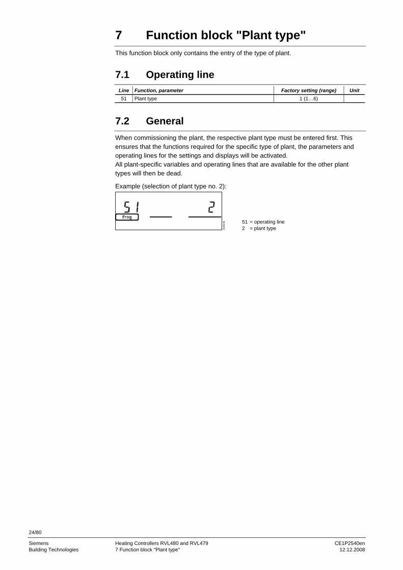
When commissioning the plant, the respective plant type must be entered first. This ensures that the functions required for the specific type of plant, the parameters and operating lines for the settings and displays will be activated. All plant-specific variables and operating lines that are available for the other plant types will then be dead.
Example (selection of plant type no. 2):
2540
Z02
512
= operating line = plant type

25/80
Siemens Heating Controllers RVL480 and RVL479 CE1P2540en Building Technologies 8 Function block "Space heating" 12.12.2008
8 Function block "Space heating"
This function block provides the ECO function, the optimization functions with boost heating and quick setback, as well as the room temperature influence.
8.1 Operating lines
Line Function, parameter Factory setting (range) Unit 61 Heating limit for NORMAL heating (ECO day) 17.0 (--.- / −5.0…+25.0) °C 62 Heating limit for REDUCED heating (ECO night) 5.0 (--.- / −5.0…+25.0) °C 63 Building time constant 20 (0…50) h 64 Quick setback 1 (0 / 1) 65 Source of the room temperature A (0 / 1 / 2 / 3 / A) 66 Type of optimization 0 (0 / 1) 67 Maximum heating-up time 00:00 (00:00…42:00) hh:mm 68 Maximum optimum shutdown 0:00 (0:00…6:00) h:mm 69 Maximum limitation of room temperature --.- (--.- / 0…35) °C 70 Gain factor for room temperature influence 4 (0…20) 71 Boost of room temperature setpoint 5 (0…20) °C 72 Parallel displacement of heating curve 0.0 (−4.5…+4.5) °C 73 Type of heating curve adjustment 0 (0…2)
8.2 ECO function
The ECO function controls the heating system depending on demand. It gives consid-eration to the development of the room temperature depending on the type of building construction as the outside temperature varies. If the amount of heat stored in the building is sufficient to maintain the room temperature setpoint currently required, the ECO function will switch the heating off. Using the ECO function, the heating system operates only, or consumes energy only when required.
8.2.1 Compensating variables and auxiliary variables
The ECO function takes into account the development of the outside temperature and the heat storage capacity of the building. The following variables are taken into consideration: • The building time constant. This is the measure of the type of building construction
and indicates how quickly the room temperature in the building would change if the outside temperature was suddenly changed. The following guide values can be used for setting the building time constant: 10 h for light building structures 25 h for medium building structures 50 h for heavy building structures
• The actual outside temperature (TA) • The composite outside temperature (TAM); it is the mean value of
− the actual outside temperature and − the outside temperature filtered by the building time constant In comparison with the actual outside temperature, the composite outside tempera-ture is attenuated. Hence, it represents the effects of short-time outside temperature variations on the room temperature as they often occur during intermediate seasons (spring time and autumn)
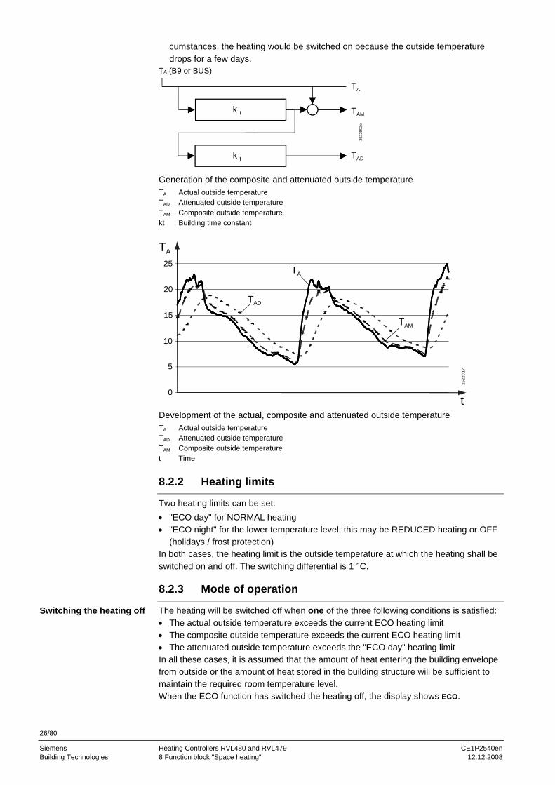
• The attenuated outside temperature (TAD). It is generated by filtering twice the actual outside temperature by the building time constant. This means that, in comparison with the actual outside temperature, the attenuated outside temperature is consid-erably dampened. This ensures that no heating will be provided in the summer when, under normal cir-
26/80
Siemens Heating Controllers RVL480 and RVL479 CE1P2540en Building Technologies 8 Function block "Space heating" 12.12.2008
cumstances, the heating would be switched on because the outside temperature drops for a few days.
TA (B9 or BUS)
2522
B02
e
TA
k t
k t
TAD
TAM
Generation of the composite and attenuated outside temperature TA Actual outside temperature TAD Attenuated outside temperature TAM Composite outside temperature kt Building time constant
0
5
10
15
20
25
TAD
TAM
t
2522
D17
TA
TA
Development of the actual, composite and attenuated outside temperature TA Actual outside temperature TAD Attenuated outside temperature TAM Composite outside temperature t Time
8.2.2 Heating limits
Two heating limits can be set: • "ECO day" for NORMAL heating • "ECO night" for the lower temperature level; this may be REDUCED heating or OFF
(holidays / frost protection) In both cases, the heating limit is the outside temperature at which the heating shall be switched on and off. The switching differential is 1 °C.
8.2.3 Mode of operation
The heating will be switched off when one of the three following conditions is satisfied: • The actual outside temperature exceeds the current ECO heating limit • The composite outside temperature exceeds the current ECO heating limit • The attenuated outside temperature exceeds the "ECO day" heating limit In all these cases, it is assumed that the amount of heat entering the building envelope from outside or the amount of heat stored in the building structure will be sufficient to maintain the required room temperature level. When the ECO function has switched the heating off, the display shows ECO.
Switching the heating off

27/80
Siemens Heating Controllers RVL480 and RVL479 CE1P2540en Building Technologies 8 Function block "Space heating" 12.12.2008
The heating will be switched on again only when all three of the following conditions are satisfied: • The actual outside temperature has fallen 1 °C below the current ECO heating limit • The composite outside temperature has fallen 1 °C below the current ECO heating limit • The attenuated outside temperature has fallen 1 °C below the "ECO day" heating limit
8.2.4 Operating modes and operational statuses
The ECO function is provided depending on the operating mode:
Operating mode or operating state ECO function Current heating limit
Automatic mode Active ECO day or ECO night
Continuously REDUCED heating Active ECO night
Continuously NORMAL heating Inactive –
Protection / holiday mode Active ECO night
Manual operation Inactive –
8.3 Room temperature source
The room temperature source can be selected on operating line 65. The following settings are possible:
Operating line 65 Room temperature source 0 No room temperature sensor 1 Room unit connected to terminal A6 2 Room temperature sensor connected to terminal B5 3 Average value of devices connected to terminals A6 and B5 A Automatic selection
Line 65 also displays the room temperature source effectively used by the controller (indicated by ACTUAL): ACTUAL = 0 Controller uses no sensor ACTUAL = 1 Controller uses the room unit connected to terminal A6 ACTUAL = 2 Controller uses the room temperature sensor connected to terminal B5 ACTUAL = 3 Controller operates with the average value delivered by the devices
connected to terminals A6 and B5
8.4 Optimization 8.4.1 Definition and purpose
Operation is optimized. EN 12098 defines optimization as "automatic shifting of the switch-on and switch-off points aimed at saving energy". This means that • switching on and heating up as well as switching off are controlled such that during
building occupancy times the required room temperature level will always be en-sured
• the smallest possible amounts of energy will be used to achieve this objective
8.4.2 Fundamentals
It is possible to select or set: • The type of optimization: either with a room temperature sensor/room unit or based
on the room model • The maximum limit value for the heating-up time • The maximum limit value for optimum shutdown • Quick setback: yes or no
Switching the heating on
28/80
Siemens Heating Controllers RVL480 and RVL479 CE1P2540en Building Technologies 8 Function block "Space heating" 12.12.2008
To perform the optimization function, the controller makes use of the actual room tem-perature – acquired by a room temperature sensor or room unit – or the room model. Using a room temperature sensor or room unit, it is possible to have optimum start control and optimum stop control. To be able to optimally determine the switch-on and switch-off points, optimization needs to "know" the building's heating up and cooling down characteristics, always in function of the prevailing outside temperature. For this purpose, optimization continually acquires the room temperature and the respective outside temperature. It captures these variables via the room temperature sensor and the outside sensor and continually adjusts the forward shift of the switching points. In this way, optimization can also detect changes made to the building and to take them into consideration. The learning process always concentrates on the first heating period per day. When no room temperature sensor is used, the room model only allows optimum start control. Optimization operates with fixed values (no learning process), based on the set maxi-mum heating up time and the room model.
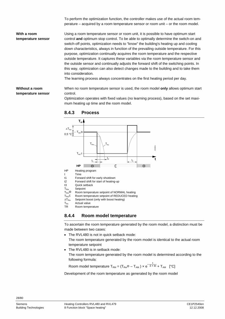
8.4.3 Process
HP
TRw TRx
TRwTRw
TRw25
40D
01
0,5 °C
TR
t
HP Heating program t Time t1 Forward shift for early shutdown t2 Forward shift for start of heating-up t3 Quick setback TRw Setpoint TRw Room temperature setpoint of NORMAL heating TRw Room temperature setpoint of REDUCED heating ΔTRw Setpoint boost (only with boost heating) TRx Actual value TR Room temperature
8.4.4 Room model temperature
To ascertain the room temperature generated by the room model, a distinction must be made between two cases: • The RVL480 is not in quick setback mode:
The room temperature generated by the room model is identical to the actual room temperature setpoint
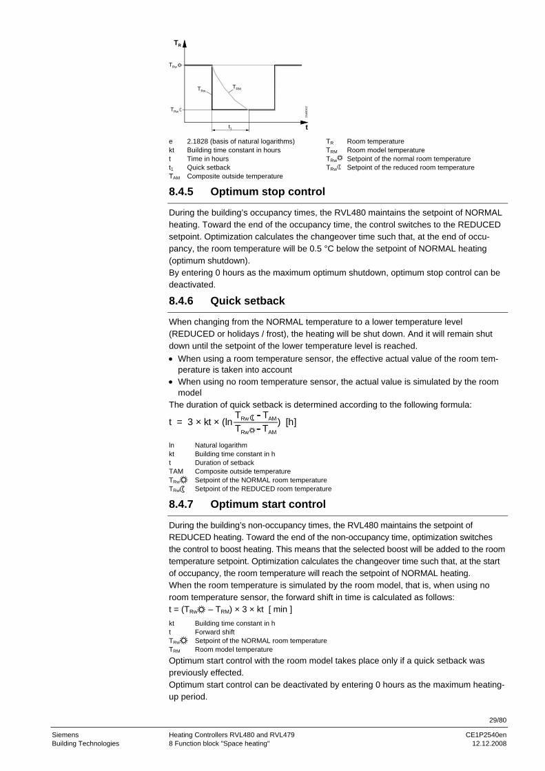
• The RVL480 is in setback mode: The room temperature generated by the room model is determined according to the following formula:
Room model temperature TRM = (TRw – TAM ) × e 3 × kt t
+ TAM [°C]
Development of the room temperature as generated by the room model
With a room temperature sensor
Without a room temperature sensor
29/80
Siemens Heating Controllers RVL480 and RVL479 CE1P2540en Building Technologies 8 Function block "Space heating" 12.12.2008
t1
TRwTRM
TRw
TRw
2540
D02
TR
t e 2.1828 (basis of natural logarithms) TR Room temperature kt Building time constant in hours TRM Room model temperature t Time in hours TRw Setpoint of the normal room temperature t1 Quick setback TRw Setpoint of the reduced room temperature TAM Composite outside temperature
8.4.5 Optimum stop control
During the building’s occupancy times, the RVL480 maintains the setpoint of NORMAL heating. Toward the end of the occupancy time, the control switches to the REDUCED setpoint. Optimization calculates the changeover time such that, at the end of occu-pancy, the room temperature will be 0.5 °C below the setpoint of NORMAL heating (optimum shutdown). By entering 0 hours as the maximum optimum shutdown, optimum stop control can be deactivated.
8.4.6 Quick setback
When changing from the NORMAL temperature to a lower temperature level (REDUCED or holidays / frost), the heating will be shut down. And it will remain shut down until the setpoint of the lower temperature level is reached. • When using a room temperature sensor, the effective actual value of the room tem-
perature is taken into account • When using no room temperature sensor, the actual value is simulated by the room
model The duration of quick setback is determined according to the following formula:
t = 3 × kt × (ln ) [h]TRw - TAM
TRw - TAM ln Natural logarithm kt Building time constant in h t Duration of setback TAM Composite outside temperature TRw Setpoint of the NORMAL room temperature TRw Setpoint of the REDUCED room temperature
8.4.7 Optimum start control
During the building’s non-occupancy times, the RVL480 maintains the setpoint of REDUCED heating. Toward the end of the non-occupancy time, optimization switches the control to boost heating. This means that the selected boost will be added to the room temperature setpoint. Optimization calculates the changeover time such that, at the start of occupancy, the room temperature will reach the setpoint of NORMAL heating. When the room temperature is simulated by the room model, that is, when using no room temperature sensor, the forward shift in time is calculated as follows: t = (TRw – TRM) × 3 × kt [ min ] kt Building time constant in h t Forward shift TRw Setpoint of the NORMAL room temperature TRM Room model temperature
Optimum start control with the room model takes place only if a quick setback was previously effected. Optimum start control can be deactivated by entering 0 hours as the maximum heating- up period.
30/80
Siemens Heating Controllers RVL480 and RVL479 CE1P2540en Building Technologies 8 Function block "Space heating" 12.12.2008
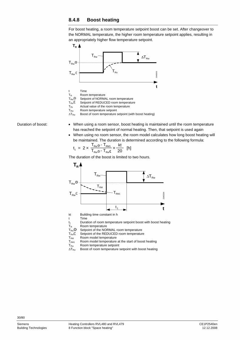
8.4.8 Boost heating
For boost heating, a room temperature setpoint boost can be set. After changeover to the NORMAL temperature, the higher room temperature setpoint applies, resulting in an appropriately higher flow temperature setpoint.
t
2540
D03
TR
TRw
TRx
TRw
TRw
TRw
t Time TR Room temperature TRw Setpoint of NORMAL room temperature TRw Setpoint of REDUCED room temperature TRx Actual value of the room temperature TRw Room temperature setpoint ΔTRw Boost of room temperature setpoint (with boost heating)
• When using a room sensor, boost heating is maintained until the room temperature
has reached the setpoint of normal heating. Then, that setpoint is used again • When using no room sensor, the room model calculates how long boost heating will
be maintained. The duration is determined according to the following formula:
t1 = 2 × [h]TRw - TRM1
TRw - TRw
kt20
×
The duration of the boost is limited to two hours.
t
2540
D04
TRM
TR
t 1
TRM1
TRw
TRw
TRw
TRw
kt Building time constant in h t Time t1 Duration of room temperature setpoint boost with boost heating TR Room temperature TRw Setpoint of the NORMAL room temperature TRw Setpoint of the REDUCED room temperature TRM Room model temperature TRM1 Room model temperature at the start of boost heating TRw Room temperature setpoint ΔTRw Boost of room temperature setpoint with boost heating
Duration of boost:

31/80
Siemens Heating Controllers RVL480 and RVL479 CE1P2540en Building Technologies 8 Function block "Space heating" 12.12.2008
8.5 Room functions 8.5.1 Maximum limitation of the room temperature
For the room temperature, it is possible to have an adjustable maximum limitation, in which case a room temperature sensor is required (sensor or room unit). If the room temperature lies 1 °C above the limit value, the room temperature setpoint will be low-ered by 4 °C. Maximum limitation of the room temperature is independent of the setting used for the room temperature influence. If the room temperature lies above the limit value, the display shows . The reduction of the flow temperature setpoint ΔTVw is calculated as follows:
ΔTVw = ΔTRw × (1 + s) [K]
-1 -0,5 0,5 1 1,5 2 2,5 3
TRw
TR
2540
D05
s Heating curve slope ΔTRw Reduction of room temperature setpoint ΔTR Deviation of room temperature from the limit value (actual value / limit value) ΔTVw Reduction of flow temperature setpoint
8.5.2 Room temperature influence
The room temperature is included in the control process, in which case a room tem-perature sensor is required (sensor or room unit). The gain factor for the room temperature influence can be adjusted. This indicates to what extent deviations of the actual room temperature from the setpoint have an impact on flow temperature control: 0 = room temperature deviations have no impact on the generation of the setpoint 20 = room temperature deviations have a maximum impact on the generation of the
setpoint The reduction of the room temperature setpoint ΔTRw is calculated according to the following formula:
VF2
ΔTRw = × (TRw - TRx) [K]
TRw
TR
TRw
The change of the flow temperature setpoint resulting from the change of the room temperature setpoint is calculated as follows: ΔTVw = ΔTRw × (1 + s) [K] s Heating curve slope TRx Actual value of room temperature TRw Room temperature setpoint ΔTR Room temperature deviation (TRw – TRx) ΔTRw Change of room temperature setpoint ΔTVw Change of flow temperature setpoint –ΔTRw Reduction of room temperature setpoint VF Gain factor +ΔTRw Increase of room temperature setpoint
32/80
Siemens Heating Controllers RVL480 and RVL479 CE1P2540en Building Technologies 8 Function block "Space heating" 12.12.2008
8.6 Heating curve
8.6.1 Purpose
With the space heating systems (plant types 1, 2 and 3), flow temperature control is always weather-compensated. Assignment of the flow temperature setpoint to the prevailing outside temperature is made via the heating curve.
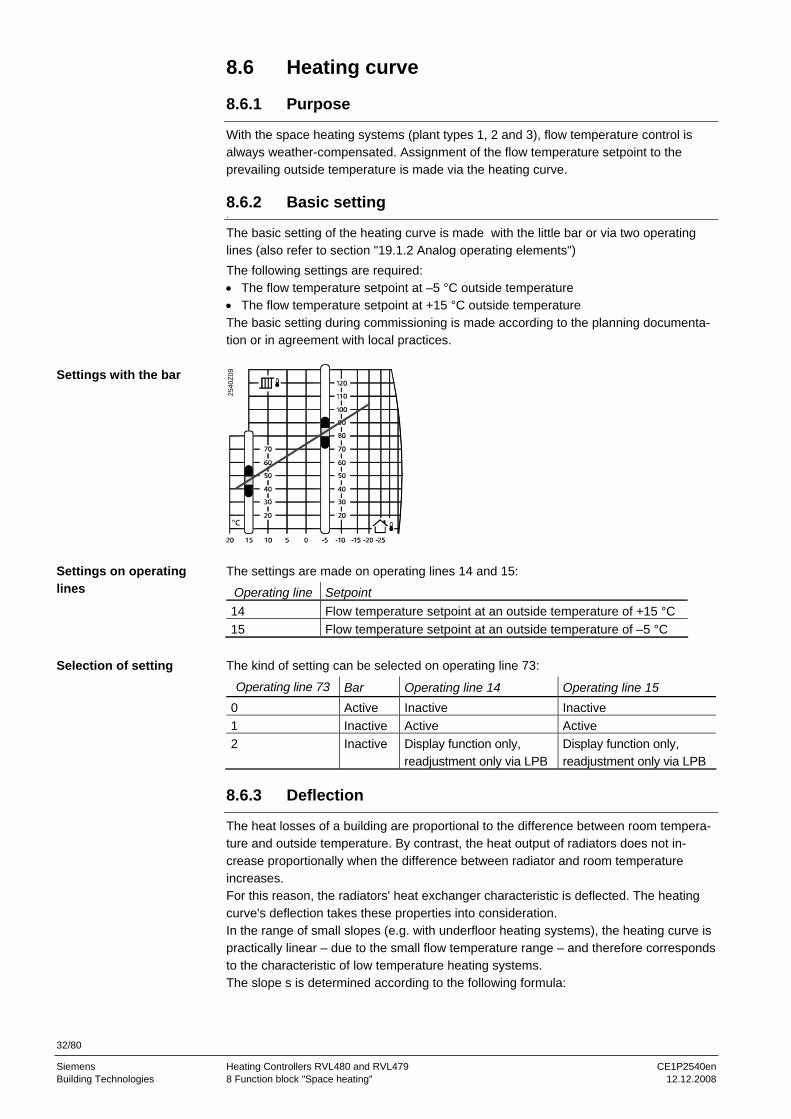
8.6.2 Basic setting .
The basic setting of the heating curve is made with the little bar or via two operating lines (also refer to section "19.1.2 Analog operating elements") The following settings are required: • The flow temperature setpoint at –5 °C outside temperature • The flow temperature setpoint at +15 °C outside temperature The basic setting during commissioning is made according to the planning documenta-tion or in agreement with local practices.
2540
Z09
The settings are made on operating lines 14 and 15:
Operating line Setpoint 14 Flow temperature setpoint at an outside temperature of +15 °C 15 Flow temperature setpoint at an outside temperature of –5 °C
The kind of setting can be selected on operating line 73:
Operating line 73 Bar Operating line 14 Operating line 15 0 Active Inactive Inactive 1 Inactive Active Active 2 Inactive Display function only,
readjustment only via LPB Display function only, readjustment only via LPB
8.6.3 Deflection
The heat losses of a building are proportional to the difference between room tempera-ture and outside temperature. By contrast, the heat output of radiators does not in-crease proportionally when the difference between radiator and room temperature increases. For this reason, the radiators' heat exchanger characteristic is deflected. The heating curve's deflection takes these properties into consideration. In the range of small slopes (e.g. with underfloor heating systems), the heating curve is practically linear – due to the small flow temperature range – and therefore corresponds to the characteristic of low temperature heating systems. The slope s is determined according to the following formula:
Settings with the bar
Settings on operating lines
Selection of setting

33/80
Siemens Heating Controllers RVL480 and RVL479 CE1P2540en Building Technologies 8 Function block "Space heating" 12.12.2008
s = TVw(-5) - TVw(+15)
20 K s Heating curve slope TVw(–5) Flow temperature setpoint at an outside temperature of –5 °C TVw(+15) Flow temperature setpoint at an outside temperature of +15 °C
On the controller, the heating curve is set as a straight line, but the straight line corre-sponds exactly to the deflected heating curve, because a non-linear outside tempera-ture scale corresponds to the deflection. The heating curve is valid for a room temperature setpoint of 20 °C.
8.6.4 Parallel displacement of heating curve
The heating curve can be displaced parallel: • Manually with the setting knob for room temperature readjustments. The readjust-
ment can be made by the end-user and covers a maximum range of –4.5…+4.5 °C room temperature
• Manually on operating line 72 This parallel displacement of the heating curve is calculated as follows: Parallel displacement ΔTFlow = (ΔTKnob + ΔTOperating line 72) × (1 + s)
10 0 -10 -20 -30
90
80
70
60
50
30
2540
D06
100
0
1010
0
30
TRw
TA
TV
20
40
Parallel displacement of the heating curve s Slope TA Outside temperature TV Flow temperature TWR Room temperature setpoint
8.6.5 Display of setpoints
Two setpoints result from the basic setting, the position of the setting knob and – if made – the entry on operating line 72, which can be called up on operating line 166: • Resulting flow temperature setpoint at an outside temperature of +15 °C • Resulting flow temperature setpoint at an outside temperature of –5 °C These two current setpoints determine the actual heating curve from which – in function of the composite outside temperature – the current flow temperature setpoint is gener-ated. It can be called up on operating line 165 (also refer to chapter "13. Function block "Service functions and general settings"").
34/80
Siemens Heating Controllers RVL480 and RVL479 CE1P2540en Building Technologies 8 Function block "Space heating" 12.12.2008
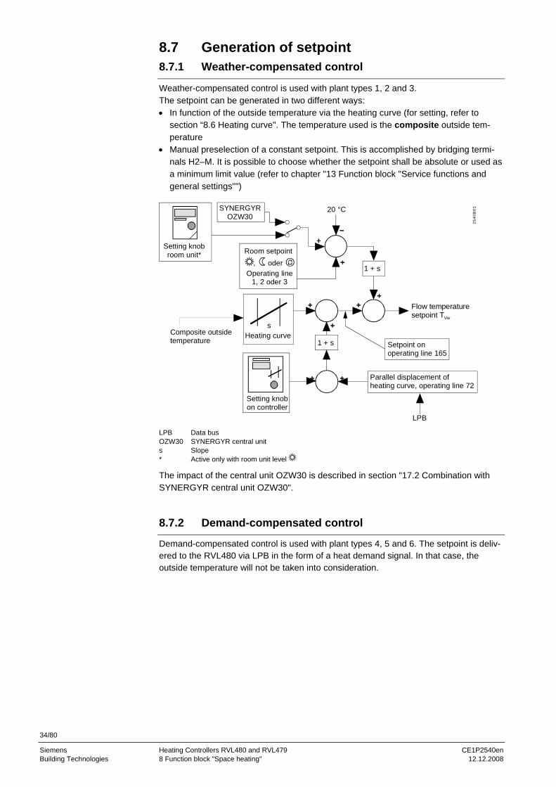
8.7 Generation of setpoint 8.7.1 Weather-compensated control
Weather-compensated control is used with plant types 1, 2 and 3. The setpoint can be generated in two different ways: • In function of the outside temperature via the heating curve (for setting, refer to
section “8.6 Heating curve". The temperature used is the composite outside tem-perature
• Manual preselection of a constant setpoint. This is accomplished by bridging termi-nals H2–M. It is possible to choose whether the setpoint shall be absolute or used as a minimum limit value (refer to chapter "13 Function block "Service functions and general settings"")
2540
B01
LPB
SYNERGYR OZW30
, oder
s
1 + s
20 °C
1 + s
Setting knob room unit* Room setpoint
Operating line1, 2 oder 3
Composite outsidetemperature
Heating curve
Setting knobon controller
Parallel displacement of heating curve, operating line 72
Setpoint onoperating line 165
Flow temperaturesetpoint TVw
LPB Data bus OZW30 SYNERGYR central unit s Slope * Active only with room unit level
The impact of the central unit OZW30 is described in section "17.2 Combination with SYNERGYR central unit OZW30".
8.7.2 Demand-compensated control
Demand-compensated control is used with plant types 4, 5 and 6. The setpoint is deliv-ered to the RVL480 via LPB in the form of a heat demand signal. In that case, the outside temperature will not be taken into consideration.

35/80
Siemens Heating Controllers RVL480 and RVL479 CE1P2540en Building Technologies 9 Function block "3-position actuator heating circuit" 12.12.2008
9 Function block "3-position actuator heating circuit"
This function block provides 3-position control. Depending on the type of plant, it acts as follows: • Weather-compensated, on the mixing valve of a space heating system
(plant type 1) • Weather-compensated, on the valve in the primary return of a space heating
system with a district heat connection (plant type 3) • Demand-compensated, on the mixing valve of a main flow (plant type 4) • Demand-compensated, on the valve in the primary return of a main flow with a
district heat connection (plant type 6)
9.1 Operating lines
Line Function, parameter Factory setting (range) Unit 81 Maximum limitation of flow temperature --- (--- / 0…140) °C 82 Minimum limitation of flow temperature --- (--- / 0…140) °C 83 Maximum rate of flow temperature increase --- (--- / 1…600) °C/h 84 Excess temperature mixing valve / heat exchanger 10 (0…50) °C 85 Actuator running time 120 (30…873) s 86 P-band of control (Xp) 32.0 (1…100) °C 87 Integral action time of control (Tn) 120 (30…873) s
9.2 Limitations
9.2.1 Limitations of the flow temperature
The following limitations can be set: • Maximum limitation of flow temperature: at the limit value, the heating curve runs
horizontal. This means that the flow temperature setpoint cannot exceed the maxi-mum value
• Minimum limitation of flow temperature: at the limit value, the heating curve runs horizontal. This means that the flow temperature setpoint cannot fall below the mini-mum value
If the setpoint is limited, the display shows: = for maximum limitation = for minimum limitation
Both limitations can be deactivated (setting ---).
9.2.2 Setpoint increase
t
t
2540
D07
TVw
TVw
Maximum slope = ΔTVw
Δt
t Time Δt Unit of time TVw Flow temperature setpoint ΔTVw Setpoint rise per unit of time

36/80
Siemens Heating Controllers RVL480 and RVL479 CE1P2540en Building Technologies 9 Function block "3-position actuator heating circuit" 12.12.2008
The rate of increase of the flow temperature setpoint can be limited to a maximum. In that case, the maximum rate of increase of the flow temperature setpoint is the selected temperature per unit of time (°C per hour). This function • prevents cracking noise in the piping • protects objects and construction materials that are sensitive to quick temperature
increases (e.g. antiquities) • prevents excessive loads on heat generating equipment This function can be deactivated (setting ---).
9.3 3-position control
3-position control operates as weather- or demand-compensated PI flow temperature control. The flow temperature is controlled through the modulating regulating unit (slip-per or seat valve). Thanks to the I-part, there is no control offset. The control's positioning commands to the actuator of the regulating unit are fed to the output relays and indicated by LEDs.
9.4 Excess mixing valve temperature
In interconnected plants, an excess mixing valve temperature can be entered on the RVL480. This is a boost of the heating zone's flow temperature setpoint. The higher setpoint is delivered to the heat generating equipment as the heat demand signal. The excess mixing valve temperature can only be set on controllers driving a mixing valve (controller N2 in the example below, operating line 84). Example:
N2
wN2wN1 = wN2 + w 2540
S07wN2 + w
wBUS (LPB)
N1 Boiler temperature controller (heat generation) N2 Flow temperature controller (heating zone) wN1 Setpoint of the boiler temperature controller wN2 Setpoint of the flow temperature controller Δw Excess mixing valve temperature (to be set on controller N2)
9.5 Pulse lock
If the actuator receives only closing or opening pulses for a period of time equivalent to five times the actuator running time, all additional pulses delivered by the controller will be locked, thus reducing the strain on the actuator. For safety reasons however, the controller delivers pulse in the opposite direction at 10-minute intervals. A pulse in the opposite direction negates the pulse lock.

37/80
Siemens Heating Controllers RVL480 and RVL479 CE1P2540en Building Technologies 10 Function block "Boiler" 12.12.2008
10 Function block "Boiler"
Function block "Boiler" acts as a 2-position controller and is used for direct burner control. Depending on the type of plant, it acts as a • boiler temperature controller for weather-compensated control of a space heating
system (plant type 2) • boiler temperature controller for demand-compensated control of a main flow (plant
type 5)
10.1 Operating lines
Line Function, parameter Factory setting (range) Unit 91 Operating mode of boiler 0 (0 / 1) 92 Maximum limitation of boiler temperature 95 (25…140) °C 93 Minimum limitation of boiler temperature 10 (5…140) °C 94 Switching differential 6 (1…20) °C 95 Minimum burner running time 4 (0…10) min 96 Release limit for second burner stage 50 (0…500) °C×min97 Reset limit for second burner stage 10 (0…500) °C×min98 Waiting time second burner stage 20 (0…40) min 99 Operating mode pump M1 1 (0 / 1)
10.2 Operating mode
When there is no demand for heat (e.g. due to the ECO function), three different boiler operating modes are available: • With manual shutdown: the boiler will be shut down when there is no demand for
heat and operating mode protection is selected (setting 0 on operating line 91) • With automatic shutdown: the boiler will be shut down when there is no demand for
heat, irrespective of the selected operating mode (setting 1 on operating line 91) Boiler operating modes, when there is no demand for heat:
Boiler operating mode Controller's operating mode with manual shutdown with automatic shutdown
Protection Boiler OFF Boiler OFF
AUTO Boiler at minimum limit value Boiler OFF
REDUCED Boiler at minimum limit value Boiler OFF
NORMAL Boiler at minimum limit value Boiler OFF
With plant type 5, it is not possible to select all operating modes (refer to section "3.4 Operating modes"). When there is demand for heat, the boiler always supplies heat, which means that the boiler's operating mode will always be ON.
10.3 Limitations
10.3.1 Maximum limitation of the boiler temperature
For maximum limitation of the boiler temperature, the maximum limit value can be adjusted. The switch-off point cannot exceed the maximum limit value. The switch-on point will then be lower by the amount of the set switching differential. If the boiler temperature is limited, the display shows . These limitations cannot be used as safety functions. For that purpose, thermostats, thermal reset limit thermostats, etc., must be used.

38/80
Siemens Heating Controllers RVL480 and RVL479 CE1P2540en Building Technologies 10 Function block "Boiler" 12.12.2008
10.3.2 Minimum limitation of the boiler return temperature
For minimum limitation of the boiler temperature, a minimum limit value can be ad-justed. The switch-on point cannot fall below the minimum limit value. The switch-off point will then be higher by the amount of the set switching differential. If the return temperature is limited, the display shows .
10.4 2-Position control
2-Position control controls the boiler temperature by switching a single- or 2-stage burner on and off. The control's commands to the burner or burner stages are fed to the output relays and indicated by LEDs.
10.4.1 Control with a single-stage burner
For 2-position control with a single-stage burner, the variables that can be set are the switching differential and the minimum burner running time. The controller compares the actual value of the boiler temperature with the setpoint. If the boiler temperature falls below the setpoint by half the switching differential, the burner will be switched on. If the boiler temperature exceeds the setpoint by half the switching differential, the burner will be switched off.
2540
D09
TK
ON
OFF
TKw
0,5×SD 0,5×SD
SD Switching differential TK Boiler temperature TKw Boiler temperature setpoint
If there is no more deviation before the minimum burner running time has elapsed, the burner will nevertheless remain activated until that time is completed (burner cycling protection). This means that the minimum burner running time has priority, provided the boiler temperature will not exceed the maximum limit, which will always lead to burner shutdown.
TKw + 0,5×SD
0
1
2540
D10
TK
TKw
TKw - 0,5×SD
TKx
tYB
SD Switching differential t Time TK Boiler temperature wTK Boiler temperature setpoint xTK Actual value of the boiler temperature YB Burner control signal
When controlling a single-stage burner, the reset limit of the second stage should be set to zero.
Note
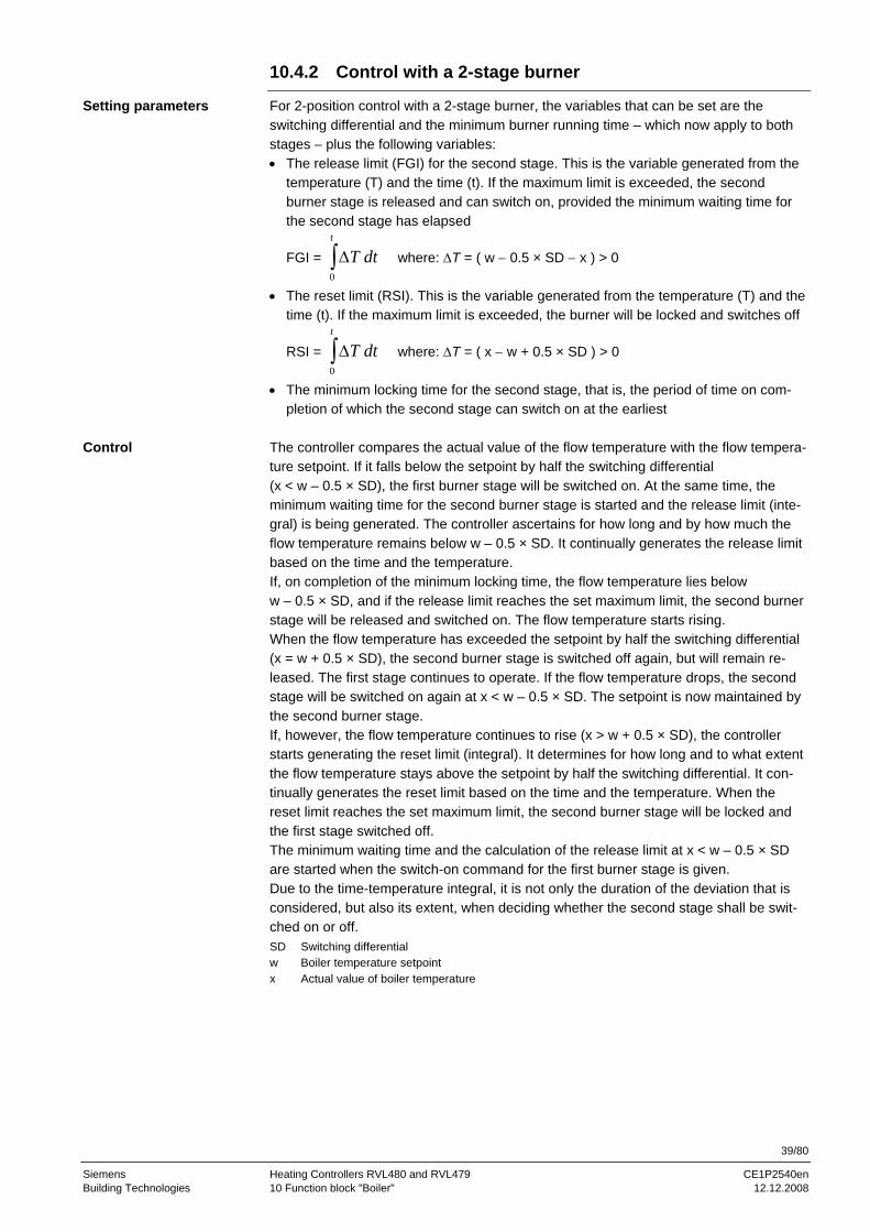
39/80
Siemens Heating Controllers RVL480 and RVL479 CE1P2540en Building Technologies 10 Function block "Boiler" 12.12.2008
10.4.2 Control with a 2-stage burner
For 2-position control with a 2-stage burner, the variables that can be set are the switching differential and the minimum burner running time – which now apply to both stages – plus the following variables: • The release limit (FGI) for the second stage. This is the variable generated from the
temperature (T) and the time (t). If the maximum limit is exceeded, the second burner stage is released and can switch on, provided the minimum waiting time for the second stage has elapsed
FGI = ΔT dtt
0∫ where: ΔT = ( w − 0.5 × SD − x ) > 0
• The reset limit (RSI). This is the variable generated from the temperature (T) and the time (t). If the maximum limit is exceeded, the burner will be locked and switches off
RSI = ΔT dtt
0∫ where: ΔT = ( x − w + 0.5 × SD ) > 0
• The minimum locking time for the second stage, that is, the period of time on com-pletion of which the second stage can switch on at the earliest
The controller compares the actual value of the flow temperature with the flow tempera-ture setpoint. If it falls below the setpoint by half the switching differential (x < w – 0.5 × SD), the first burner stage will be switched on. At the same time, the minimum waiting time for the second burner stage is started and the release limit (inte-gral) is being generated. The controller ascertains for how long and by how much the flow temperature remains below w – 0.5 × SD. It continually generates the release limit based on the time and the temperature. If, on completion of the minimum locking time, the flow temperature lies below w – 0.5 × SD, and if the release limit reaches the set maximum limit, the second burner stage will be released and switched on. The flow temperature starts rising. When the flow temperature has exceeded the setpoint by half the switching differential (x = w + 0.5 × SD), the second burner stage is switched off again, but will remain re-leased. The first stage continues to operate. If the flow temperature drops, the second stage will be switched on again at x < w – 0.5 × SD. The setpoint is now maintained by the second burner stage. If, however, the flow temperature continues to rise (x > w + 0.5 × SD), the controller starts generating the reset limit (integral). It determines for how long and to what extent the flow temperature stays above the setpoint by half the switching differential. It con-tinually generates the reset limit based on the time and the temperature. When the reset limit reaches the set maximum limit, the second burner stage will be locked and the first stage switched off. The minimum waiting time and the calculation of the release limit at x < w – 0.5 × SD are started when the switch-on command for the first burner stage is given. Due to the time-temperature integral, it is not only the duration of the deviation that is considered, but also its extent, when deciding whether the second stage shall be swit-ched on or off. SD Switching differential w Boiler temperature setpoint x Actual value of boiler temperature
Setting parameters
Control

40/80
Siemens Heating Controllers RVL480 and RVL479 CE1P2540en Building Technologies 10 Function block "Boiler" 12.12.2008
1
0
INTmax.
FGB2
1
0
YB2
t
FGI RSI
2522
D09
0
1
0
t
t
t
t
YB1
max.
TKw + 0,5 * SD
TKw - 0,5 * SD
TKx
RSI
FGB2 Release of burner stage 2 t Time FGI Release limit TKw Boiler temperature setpoint INT Integral TKx Actual value of the boiler temperature RSI Reset limit YB1 Control signal for burner stage 1 SD Switching differential YB2 Control signal for burner stage 2
10.4.3 Frost protection for the boiler
Frost protection for the boiler uses fixed values: • Switch-on point: 5 °C boiler temperature • Switch-off point: minimum limit of boiler temperature plus switching differential If the boiler temperature falls below 5 °C, the burner will always be switched on until the boiler temperature has crossed the minimum limit by the amount of the switching differential.
10.4.4 Protective boiler startup
If, while the burner is running, the boiler temperature falls below the minimum limit of the boiler temperature, the differential (minimum limit value minus actual value) will be integrated. From this, a critical locking signal will be generated and transmitted to the connected loads. This causes the loads to reduce their setpoints, thus consuming less energy. If the critical locking signal exceeds a defined value, the boiler pump will be deactivated also. If the boiler temperature returns to a level above the minimum limit, the integral will be reduced, resulting in a reduction of the critical locking signal. If the integral reaches a defined limit, the boiler pump will be activated again, and the connected loads raise their setpoints again. When the integral reaches the value of zero, protective boiler startup will be deacti-vated, in which case the critical locking signal is zero. If the boiler effects protective boiler startup, the boiler temperature controller's display shows . Protective boiler startup cannot be deactivated.

41/80
Siemens Heating Controllers RVL480 and RVL479 CE1P2540en Building Technologies 10 Function block "Boiler" 12.12.2008
Section "13.4.7 Gain of locking signal" provides information on who receives the boiler temperature controller's critical locking signal and how the loads respond to it.
Controller 1Plant type 2
Controller 1Plant type 5
Controller 2
Controller 1 generates a critical locking signal which deactivates the heating circuit pump
Critical locking signal
LPB
Individual unit:
Interconnected plant:
2522
B05
Controller 1 switchesboiler pump off
Critical locking signal
Controller 3
10.4.5 Protection against boiler overtemperatures
To prevent heat from building up in the boilers (protection against overtemperatures), the RVL480 offers a protective function. When the first burner stage is switched off, the controller allows the boiler pump to overrun for the set pump overrun time (operating line 174 on the boiler temperature controller), generating at the same time a forced signal to all loads (inside the controller on the data bus). If the boiler temperature controller is located in segment 0, the forced signal will be delivered to all loads in all segments. By contrast, if the boiler temperature controller is located in segment 1…14, the signal will only be sent to the loads in the same segment.
t
2522
D13
e
Boiler controller, stage 1
Forced signal
Overrun timeof boiler pump
Pump
Off
Y
t Time Y Control signal boiler pump
All loads (heating and d.h.w. circuits) and heat exchangers that abruptly reduce their demand for heat watch the data bus during the set pump overrun time to see if a forced signal is being sent by the boiler. • If no forced signal is received, the loads and the heat exchanger only allow pump
overrun to take place (refer to section "13.4.4 Pump overrun") • If, in this time window, a forced signal is received, the loads continue to draw heat
from the boiler in the following manner: − Plant types with heating circuits using a mixing valve maintain the previous set-
point − Plant types with pump heating circuits allow the pumps to continue running
If the boiler sets the forced signal to zero, the loads and heat exchanges that have responded to the forced signal respond as follows: • They close the slipper or seat valves • Their pumps run for the set pump overrun time and then stop
42/80
Siemens Heating Controllers RVL480 and RVL479 CE1P2540en Building Technologies 10 Function block "Boiler" 12.12.2008
10.5 Operating mode of pump M1
The operating mode during protective boiler startup of the pump M1 must be selected on operating line 99: • Circulating pump with no deactivation (setting 0):
The circulating pump runs when one of the consumers calls for heat and when burner stage 1 is switched on, that is, also during protective boiler startup.
• Circulating pump with deactivation (setting 1): The circulating pump runs when one of the consumers calls for heat. It is deactivated during protective boiler startup.

43/80
Siemens Heating Controllers RVL480 and RVL479 CE1P2540en Building Technologies 11 Function block "Setpoint of return temperature limitation" 12.12.2008
11 Function block "Setpoint of return temperature limitation"
On the function block "Setpoint of return temperature limitation", the setpoint of mini-mum limitation of the return temperature or the constant value for shifting maximum limitation of the return temperature can be adjusted.
11.1 Operating line
Line Function, parameter Factory setting (range) Unit 101 Minimum limitation of return temperature --- (--- / 0…140) °C
11.2 Description
On operating line 101, the setpoint resp. the constant value is adjusted on operating line 101. When entering ---, the function is deactivated, which means that the return temperature will not be limited. For more detailed information about these functions, refer to chapter “12 Function block "District heat"”. If the settings of this function block have been locked (contact H3 or on operating line 248), the display shows when pressing buttons and .
11.3 Minimum limitation of the return temperature
This function block ensures minimum limitation of the boiler return temperature where possible or required. This applies to the following plant types: • Plant type no. 1, Heating circuit control with mixing group • Plant type no. 4, Precontrol with mixing group, heat demand signal via data bus • Plant type no. 5, Precontrol with boiler, heat demand signal via data bus Minimum limitation of the boiler return temperature prevents boiler corrosion resulting from flue gas condensation.
11.3.1 Acquisition of the measured values
A temperature sensor with a sensing element LG-Ni 1000 is required in the return. With plant type no. 1, the return temperature can also be delivered via LPB. In intercon-nected plants, only one return temperature sensor per segment may be used.
11.3.2 Mode of operation
If the return temperature falls below the set minimum limit value, the temperature differ-ential between minimum limit value and actual value will be integrated. From this, a critical locking signal will be generated and transmitted to the connected loads. This causes the loads to reduce their setpoints, thus consuming less energy. If the return temperature returns to a level above the minimum return temperature limit, the integral will be reduced, resulting in a reduction of the critical locking signal, and connected loads raise their setpoints again. When the integral reaches the value of zero, the minimum return temperature limitation will be deactivated, in which case the critical locking signal is zero. If minimum limitation of the return temperature is active, the display shows . Minimum limitation of the return temperature can be deactivated. Section provides 13.4.7 “Gain of locking signal” information on which the critical locking signal is sent to and how the loads respond to it. The minimum limit value is to be set on operating line 101. Setting --- = inactive.

44/80
Siemens Heating Controllers RVL480 and RVL479 CE1P2540en Building Technologies 11 Function block "Setpoint of return temperature limitation" 12.12.2008
11.3.3 Mode of operation with a single unit (with no bus)
No facility for min.limitation of return temp. 25
22B0
6e
Setting operating line 101 = 50 °C, return temp. sensor connected
Controller 1 Boiler controller
Controller 2 Plant type 1
Controller 2 generates a critical locking signal which closes the mixing valve
11.3.4 Mode of operation in interconnected plants
Controller 1 Plant type 5
Controller 2 Plant type 1
Controller 3 Plant type 1
Critical locking signal
Controller 2 closesthe mixing valve
Controller 3 closesthe mixing valve
LPB
2522
B07e
Setting operating line 101 = 50 °C,return temperature sensor connected
Critical locking signal
Setting operating line 101 = - - - , no own return temp. sensor connected
Setting operating 101 = - - - , no own return temp. sensor connected
Controller 2Plant type 1
Controller 3Plant type 1
Return temperature signal
Controller 2 limits return temp. to 50 °C
LPB
2522
B08e
Setting operating line 101 = 50 °C, return temp. sensor connected
Setting operating line 101 = 40 °C, no own return temp. sensor connected
Controller 3 limitsreturn temp. to 40 °C
Controller 1 Boiler controller
(no facility for min. limitation of return temp.)
The group controller with its own return temperature sensor (plant type 1) passes the return temperature to the other zone controllers in the same segment, which can provide minimum limitation of the return temperature on a local basis, depending on the settings made. This means they generate a critical locking signal internally. For response to critical locking signals, refer to section "13.4.7 Gain of locking signal".
Central impact of limitation
Local impact of limitation
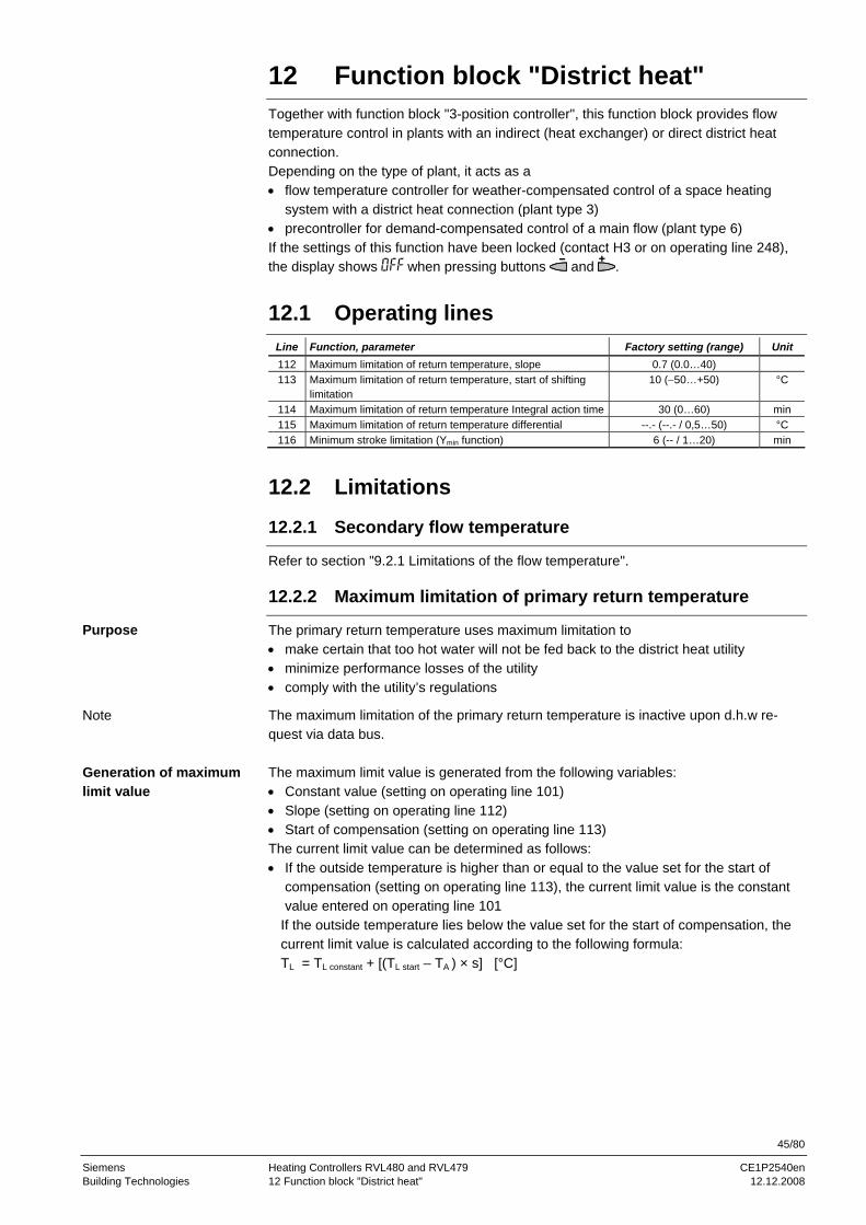
45/80
Siemens Heating Controllers RVL480 and RVL479 CE1P2540en Building Technologies 12 Function block "District heat" 12.12.2008
12 Function block "District heat"
Together with function block "3-position controller", this function block provides flow temperature control in plants with an indirect (heat exchanger) or direct district heat connection. Depending on the type of plant, it acts as a • flow temperature controller for weather-compensated control of a space heating
system with a district heat connection (plant type 3) • precontroller for demand-compensated control of a main flow (plant type 6) If the settings of this function have been locked (contact H3 or on operating line 248), the display shows when pressing buttons and .
12.1 Operating lines
Line Function, parameter Factory setting (range) Unit 112 Maximum limitation of return temperature, slope 0.7 (0.0…40) 113 Maximum limitation of return temperature, start of shifting
limitation 10 (−50…+50) °C
114 Maximum limitation of return temperature Integral action time 30 (0…60) min 115 Maximum limitation of return temperature differential --.- (--.- / 0,5…50) °C 116 Minimum stroke limitation (Ymin function) 6 (-- / 1…20) min
12.2 Limitations
12.2.1 Secondary flow temperature
Refer to section "9.2.1 Limitations of the flow temperature".
12.2.2 Maximum limitation of primary return temperature
The primary return temperature uses maximum limitation to • make certain that too hot water will not be fed back to the district heat utility • minimize performance losses of the utility • comply with the utility’s regulations
The maximum limitation of the primary return temperature is inactive upon d.h.w re-quest via data bus. The maximum limit value is generated from the following variables: • Constant value (setting on operating line 101) • Slope (setting on operating line 112) • Start of compensation (setting on operating line 113) The current limit value can be determined as follows: • If the outside temperature is higher than or equal to the value set for the start of
compensation (setting on operating line 113), the current limit value is the constant value entered on operating line 101
If the outside temperature lies below the value set for the start of compensation, the current limit value is calculated according to the following formula: TL = TL constant + [(TL start – TA ) × s] [°C]
Purpose
Note
Generation of maximum limit value

46/80
Siemens Heating Controllers RVL480 and RVL479 CE1P2540en Building Technologies 12 Function block "District heat" 12.12.2008
TPR
TA
s
90
80
70
60
50
40
30
20
20 10 0 -1030
TL constant
TL start
2381
D03
s Slope of limitation (operating line 112) TA Actual outside temperature TL constant Constant value of limitation (operating line 101) TL start Start of shifting limitation (operating line 113) TPR Primary return temperature
The outside temperature is used as a compensating variable for maximum limitation of the primary return temperature. It can be delivered either by the local sensor or the LPB. Limitation operates according to the selected characteristic: • When the outside temperature falls, the return temperature will initially be limited to
the constant value • If the outside temperature continues to fall, it will reach the selected starting point for
shifting compensation. From this point, the limit value will be raised as the outside temperature falls. The slope of this section of the characteristic can be adjusted
Maximum limitation of the return temperature has priority over maximum limitation of the flow temperature. This function can be deactivated on operating line 101. If the return temperature is limited, the display shows .
12.2.3 Maximum limitation of the return temperature differential (DRT limitation)
For the differential of primary return and secondary return temperature, a maximum limitation can be set. For this purpose, a temperature sensor (sensing element LG-Ni 1000) is required in the secondary return. If the differential of the two return temperatures exceeds the adjusted maximum limit, the flow temperature setpoint will be reduced. If maximum limitation of the return temperature differential is activated, the display shows . DRT limitation has priority over minimum limitation of the flow temperature. This function can be deactivated (setting --- on operating line 115). Limitation of the return temperature differential • prevents idle heat resulting from excessive cooling down • optimizes the volumetric flow • is a dynamic return temperature limitation • shaves peak loads • ensures the lowest possible return temperatures
Function
Function
Purpose
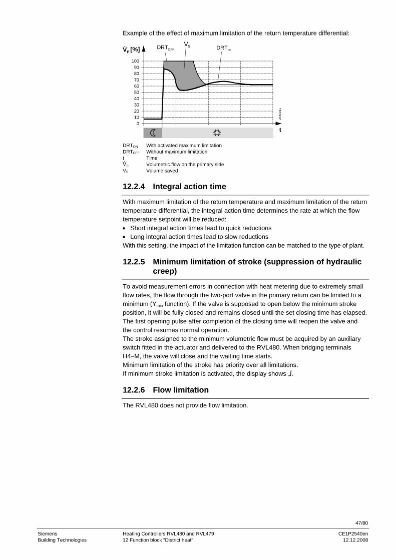
47/80
Siemens Heating Controllers RVL480 and RVL479 CE1P2540en Building Technologies 12 Function block "District heat" 12.12.2008
Example of the effect of maximum limitation of the return temperature differential:
1009080706050403020100
DRTonDRTOFFVS
t
2540
D11
[%]VP
DRTON With activated maximum limitation DRTOFF Without maximum limitation t Time
Volumetric flow on the primary side VS Volume saved
12.2.4 Integral action time
With maximum limitation of the return temperature and maximum limitation of the return temperature differential, the integral action time determines the rate at which the flow temperature setpoint will be reduced: • Short integral action times lead to quick reductions • Long integral action times lead to slow reductions With this setting, the impact of the limitation function can be matched to the type of plant.
12.2.5 Minimum limitation of stroke (suppression of hydraulic creep)
To avoid measurement errors in connection with heat metering due to extremely small flow rates, the flow through the two-port valve in the primary return can be limited to a minimum (Ymin function). If the valve is supposed to open below the minimum stroke position, it will be fully closed and remains closed until the set closing time has elapsed. The first opening pulse after completion of the closing time will reopen the valve and the control resumes normal operation. The stroke assigned to the minimum volumetric flow must be acquired by an auxiliary switch fitted in the actuator and delivered to the RVL480. When bridging terminals H4–M, the valve will close and the waiting time starts. Minimum limitation of the stroke has priority over all limitations. If minimum stroke limitation is activated, the display shows .
12.2.6 Flow limitation
The RVL480 does not provide flow limitation.

48/80
Siemens Heating Controllers RVL480 and RVL479 CE1P2540en Building Technologies 13 Function block "Service functions and general settings" 12.12.2008
13 Function block "Service functions and general settings"
Function block "Service functions and general settings” is used to combine various displays and setting functions that are of assistance in connection with commissioning and service work. In addition, a number of extra functions are performed. The service functions are independent of the type of plant. Function block Service functions and general settings
13.1 Operating lines
Line Function, parameter Factory setting (range) Unit 161 Outside temperature simulation --.- (--.- / −50…+50) °C 162 Relay test 0 (0…4) 163 Sensor test Display function 164 Test of H-contacts Display function 165 Flow temperature setpoint Display function 166 Resulting heating curve Display function 167 Outside temp. for frost protection for the plant 2.0 (--.- / 0…25) °C 168 Flow temp. setpoint for frost protection for the plant 15 (0…140) °C 169 Device number 0 (0…16) 170 Segment number 0 (0…14) 171 Flow alarm --:-- (--:-- / 1:00…10:00) hh:mm 172 Operating mode when terminals H1–M are bridged 0 (0…3) 173 Amplification of locking signal 100 (0…200) % 174 Pump overrun time 6 (0…40) min 175 Periodic pump run (pump kick) 0 (0 / 1) 176 Winter- / summertime changeover 25.03 (01.01…31.12) dd:MM 177 Summer- / wintertime changeover 25.10 (01.01…31.12) dd:MM 178 Clock operation 0 (0…3) 179 Bus power supply A (0 / A) 180 Outside temperature source A (A / 00.01… 14.16) 181 Heat demand output Ux DC 0…10 V 130 (30…130) °C
13.2 Display functions
13.2.1 Flow temperature setpoint
Displayed is the current flow temperature setpoint which is composed of the following variables: • Flow temperature setpoint in function of the composite outside temperature and the
heating curve • Position of the setting knob for room temperature readjustments • Parallel displacement of heating curve (setting on operating line 72) With demand-compensated control (plant types 4, 5 and 6), the display shows --- .
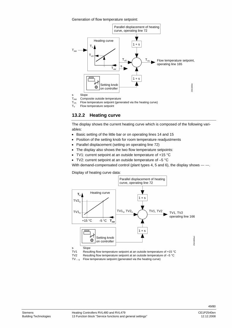
49/80
Siemens Heating Controllers RVL480 and RVL479 CE1P2540en Building Technologies 13 Function block "Service functions and general settings" 12.12.2008
Generation of flow temperature setpoint:
Flow temperature setpoint,operating line 165
1 + s
Parallel displacement of heating curve, operating line 72
1 + s
2541
B04
e
TV
TAM
TVS
Heating curve
TVwTVS
s
Setting knobon controller
TAM
s Slope TAM Composite outside temperature TVS Flow temperature setpoint (generated via the heating curve) TV Flow temperature setpoint
13.2.2 Heating curve
The display shows the current heating curve which is composed of the following vari-ables: • Basic setting of the little bar or on operating lines 14 and 15 • Position of the setting knob for room temperature readjustments • Parallel displacement (setting on operating line 72) • The display also shows the two flow temperature setpoints: • TV1: current setpoint at an outside temperature of +15 °C • TV2: current setpoint at an outside temperature of –5 °C With demand-compensated control (plant types 4, 5 and 6), the display shows --- ---.
Display of heating curve data:
TV1, TV2 operating line 166
Parallel displacement of heating curve, operating line 72
1 + s25
41B
05en
TV
TAM
Heating curve
TV2S
TV1S
+15 °C -5 °C
TV1S, TV2S TV1, TV2
1 + s
Setting knobon controller
s Slope TV1 Resulting flow temperature setpoint at an outside temperature of +15 °C TV2 Resulting flow temperature setpoint at an outside temperature of –5 °C TV…S Flow temperature setpoint (generated via the heating curve)

50/80
Siemens Heating Controllers RVL480 and RVL479 CE1P2540en Building Technologies 13 Function block "Service functions and general settings" 12.12.2008
13.3 Commissioning aids
13.3.1 Simulation of outside temperature
To facilitate commissioning and fault tracing, outside temperatures in the range of –50 to +50 °C can be simulated. This simulation has an effect on the actual, the com-posite and the attenuated outside temperature. Simulated TA = actual TA = composite TA = attenuated TA
During the simulation, the actual outside temperature (as acquired by the sensor or via LPB) will be overridden. When the simulation is terminated, the actual temperature will gradually adjust the composite and the attenuated temperatures to their real values. This simulation of the outside temperature causes therefore a reset of the composite and the attenuated outside temperatures. There are three choices to terminate the simulation: • Entry of --.- • Leaving the setting level by pressing the Info button or any of the operating mode
buttons • Automatically after 30 minutes
13.3.2 Relay test
Each of the three output relays can be energized. Depending on the type of plant, the following codings apply:
Entry Plants with a valve (plant types no. 1, 3, 4 and 6)
Plants with a burner (plant types no. 2 and 5)
0 Normal operation Normal operation 1 All contacts open All contacts open 2 Heating circuit valve fully OPEN (Y1) Burner stage 1 ON (K4) 3 Heating circuit valve fully CLOSED (Y2) Burner stages 1 and 2 ON (K5) 4 Heating circuit pump/circulating pump
ON (M1) Heating circuit pump/circulating pump ON (M1)
There are four choices to terminate the relay test: • Entry of 0 on the operating line • Leaving the setting level by pressing button or • Leaving the setting level by pressing the Info button or any of the operating mode
buttons • Automatically after 30 minutes
13.3.3 Sensor test
The connected sensors can be checked on operating line 163. In addition, if available, the current setpoints and limit values are displayed. In the display, the current setpoints are identified by SET, the actual values by ACTUAL (also refer to section "19.1 Operation "). The six temperatures can be called up by entering 0…5:

51/80
Siemens Heating Controllers RVL480 and RVL479 CE1P2540en Building Technologies 13 Function block "Service functions and general settings" 12.12.2008
Entry Display SET Display ACTUAL
0 No display Actual value of outside sensor at termi-nal B9. If the outside temperature is delivered via the data bus, the display shows ---
1 Setpoint of flow / boiler temperature. With the plant types using a boiler, the switch-on or the switch-off point is displayed. If there is no demand for heat, the display shows ---
Actual value of flow / boiler temperature sensor at terminal B1
2 Setpoint of room temperature. With the plant types with no heating circuit, no room temperature setpoint is displayed
Actual value of room temperature sen-sor at terminal B5
3 Setpoint of room temperature. With the plant types with no heating circuit, no room temperature setpoint is displayed
Actual value of room unit sensor at terminal A6
4 Limit value of return temperature. With plant types no. 1, 4 and 5, the minimum limit value of the return temperature is displayed; with plant types no. 3 and 6, the maximum limit value of the return temperature. If no return temperature limitation is activated, the display shows ---
Actual value of primary return tempera-ture sensor at terminal B7. If the return temperature is delivered via LPB, the display shows ---
5 Limit value of return temperature differential. If no DRT limitation is activated, the display shows ---
Actual value of secondary return tem-perature sensor at terminal B71
Faults in the sensor measuring circuits are displayed as follows: = short-circuit (thermostat: contact closed) = open-circuit (thermostat: contact open)
13.3.4 Test of H-contacts
The connected H-contacts can be checked on operating line 164. It is always the cur-rent status that is indicated (contact open, contact closed). The contacts can be individually selected by pressing and .
Entry Contact H1 Overriding the operating mode (contact H1) H2 Manually generated heat demand (contact H2) H3 Operating lock (contact H3) H4 Minimum limitation of stroke (contact H4)
The contact's status is displayed as follows: = contact closed = contact open

52/80
Siemens Heating Controllers RVL480 and RVL479 CE1P2540en Building Technologies 13 Function block "Service functions and general settings" 12.12.2008
13.4 Auxiliary functions
13.4.1 Frost protection for the plant
The plant can be protected against frost, provided the RVL480 and heat generation are ready to operate (mains voltage present!). The following settings are required: • The actual outside temperature at which frost protection shall respond • The minimum flow temperature that shall be maintained by the frost protection function
2540
D08
OpL 167 TA
ON
OFF
0.5 °C 0.5 °C
OpL167 Operating line 167 OFF Frost protection OFF ON Frost protection ON TA Outside temperature
If the actual outside temperature falls below the limit value (setting on operating line 167 minus 0.5 °C), the RVL480 will switch the circulating pump (pump connected to terminal Q1) on and maintain the flow temperature at the selected minimum level. The control switches off when the outside temperature exceeds the limit value by 0.5 °C. Frost protection for the plant can be deactivated.
13.4.2 Flow alarm
The fault alarm triggers a fault status message if the flow resp. the boiler temperature (depending on the plant type) does not reach the required setpoint band (setpoint ± a defined switching differential) within a defined period of time – provided there is a de-mand for heat. This period of time can be set on operating line 171. • Plant types 1, 3, 4 and 6: Important is the temperature measured with sensor B1.
The switching differential corresponds to the neutral zone (±1 °C). • Plant types 2 and 5: Important is the temperature measured with sensor B1. The
switching differential corresponds to the set switching differential of the boiler (±0.5 × SD; operating line 94)
With plant types using a boiler, the switching differential corresponds to the set switch-ing differential (± 0.5 × SD), and with plant types using a mixing valve, to the neutral zone (±1 °C). The display shows the fault status message as . More detailed information is given on operating line 50 under error code 120. The flow alarm can be deactivated by entering --:--.

53/80
Siemens Heating Controllers RVL480 and RVL479 CE1P2540en Building Technologies 13 Function block "Service functions and general settings" 12.12.2008
t
TV
w x
2540
D12tA
tA
tA
t1 t2
y
t Time t1 Start of error display t2 End of error display tA Waiting time (set on operating line 171) TV Flow temperature w Setpoint x Actual value y Setpoint band
• At t1, a fault status message is triggered; during the period of time tA (set on operat-ing line 171), the actual value stayed below the setpoint band y
• At t2, the fault status message is reset; the actual value x has reached the setpoint band y
13.4.3 Manual overriding of operating mode (contact H1)
Using a simple remote operation facility, the controller's operating mode can be over-ridden. This is accomplished by bridging terminals H1–M. It is possible to select the operating mode that shall apply when H1–M are bridged:
Setting Operating mode heating circuit
0 Protection
1 AUTO
2 REDUCED
3 NORMAL
As long as this function is activated, the LED of the respective operating mode button flashes at low frequency (approx. 0.5 Hz). The buttons themselves are however inoper-able. Once this function is deactivated, the RVL480 will resume the operating mode previ-ously selected. Contact H1 has priority over contact H2 (refer to the section below). If both contacts are activated (closed), contact H2 is inactive. With plant types 4, 5 and 6, contact H1 is inactive.
13.4.4 Pump overrun
To prevent heat from building up, a common pump overrun time can be set for all pumps associated with the controller (with the exception of the circulating pump) on operating line 174. In that case, the pump overrun maintains the charging position for the set period of time. In interconnected plants, the time set also affects the forced signals that a boiler can deliver to ensure overtemperature protection. For detailed information, refer to section "10.4.5 Protection against boiler overtempera-tures".
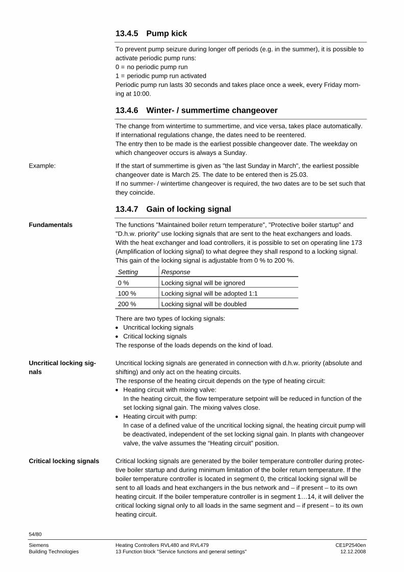
54/80
Siemens Heating Controllers RVL480 and RVL479 CE1P2540en Building Technologies 13 Function block "Service functions and general settings" 12.12.2008
13.4.5 Pump kick
To prevent pump seizure during longer off periods (e.g. in the summer), it is possible to activate periodic pump runs: 0 = no periodic pump run 1 = periodic pump run activated Periodic pump run lasts 30 seconds and takes place once a week, every Friday morn-ing at 10:00.
13.4.6 Winter- / summertime changeover
The change from wintertime to summertime, and vice versa, takes place automatically. If international regulations change, the dates need to be reentered. The entry then to be made is the earliest possible changeover date. The weekday on which changeover occurs is always a Sunday.
If the start of summertime is given as "the last Sunday in March", the earliest possible changeover date is March 25. The date to be entered then is 25.03. If no summer- / wintertime changeover is required, the two dates are to be set such that they coincide.
13.4.7 Gain of locking signal
The functions "Maintained boiler return temperature", "Protective boiler startup" and "D.h.w. priority" use locking signals that are sent to the heat exchangers and loads. With the heat exchanger and load controllers, it is possible to set on operating line 173 (Amplification of locking signal) to what degree they shall respond to a locking signal. This gain of the locking signal is adjustable from 0 % to 200 %.
Setting Response
0 % Locking signal will be ignored 100 % Locking signal will be adopted 1:1 200 % Locking signal will be doubled
There are two types of locking signals: • Uncritical locking signals • Critical locking signals The response of the loads depends on the kind of load. Uncritical locking signals are generated in connection with d.h.w. priority (absolute and shifting) and only act on the heating circuits. The response of the heating circuit depends on the type of heating circuit: • Heating circuit with mixing valve:
In the heating circuit, the flow temperature setpoint will be reduced in function of the set locking signal gain. The mixing valves close.
• Heating circuit with pump: In case of a defined value of the uncritical locking signal, the heating circuit pump will be deactivated, independent of the set locking signal gain. In plants with changeover valve, the valve assumes the “Heating circuit” position.
Critical locking signals are generated by the boiler temperature controller during protec-tive boiler startup and during minimum limitation of the boiler return temperature. If the boiler temperature controller is located in segment 0, the critical locking signal will be sent to all loads and heat exchangers in the bus network and – if present – to its own heating circuit. If the boiler temperature controller is in segment 1…14, it will deliver the critical locking signal only to all loads in the same segment and – if present – to its own heating circuit.
Example:
Fundamentals
Uncritical locking sig-nals
Critical locking signals
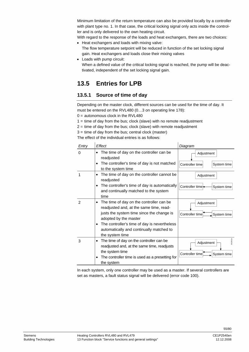
55/80
Siemens Heating Controllers RVL480 and RVL479 CE1P2540en Building Technologies 13 Function block "Service functions and general settings" 12.12.2008
Minimum limitation of the return temperature can also be provided locally by a controller with plant type no. 1. In that case, the critical locking signal only acts inside the control-ler and is only delivered to the own heating circuit. With regard to the response of the loads and heat exchangers, there are two choices: • Heat exchangers and loads with mixing valve:
The flow temperature setpoint will be reduced in function of the set locking signal gain. Heat exchangers and loads close their mixing valves
• Loads with pump circuit: When a defined value of the critical locking signal is reached, the pump will be deac-tivated, independent of the set locking signal gain.
13.5 Entries for LPB
13.5.1 Source of time of day
Depending on the master clock, different sources can be used for the time of day. It must be entered on the RVL480 (0…3 on operating line 178): 0 = autonomous clock in the RVL480 1 = time of day from the bus; clock (slave) with no remote readjustment 2 = time of day from the bus; clock (slave) with remote readjustment 3 = time of day from the bus; central clock (master) The effect of the individual entries is as follows:
Entry Effect Diagram
0 • The time of day on the controller can be readjusted
• The controller's time of day is not matched to the system time
Controller time System time
Adjustment
1 • The time of day on the controller cannot be readjusted
• The controller's time of day is automatically and continually matched to the system time
System time
Adjustment
Controller time
2 • The time of day on the controller can be readjusted and, at the same time, read-justs the system time since the change is adopted by the master
• The controller's time of day is nevertheless automatically and continually matched to the system time
System time
Adjustment
Controller time
3 • The time of day on the controller can be readjusted and, at the same time, readjusts the system time
• The controller time is used as a presetting for the system
2522
B12
e
System time
Adjustment
Controller time
In each system, only one controller may be used as a master. If several controllers are set as masters, a fault status signal will be delivered (error code 100).
56/80
Siemens Heating Controllers RVL480 and RVL479 CE1P2540en Building Technologies 13 Function block "Service functions and general settings" 12.12.2008
13.5.2 Source of outside temperature
If, in interconnected plants, the outside temperature is delivered by the bus, the tem-perature source can be addressed either automatically or directly (operating line 180). • Automatic addressing:
Display, entry Explanation SET A (For automatic addressing) ACTUAL xx.yy Display of source address selected by automatic ad-
dressing: xx = segment number yy = device number
• Direct addressing: To be entered is the source address: xx.yy xx = segment number yy = device number
If the controller is operated autonomously (with no bus), there will be no display and an entry is not possible. If the controller is used in an interconnected plant and if it has its own outside sensor, it is not possible to enter an address (if an entry is made, the display shows OFF). In that case, the controller always uses the outside temperature signal delivered by its own sensor. The address displayed is its own. For detailed information about addressing of the outside temperature source, refer to data sheet N2030.
13.5.3 Addressing of devices
Each device connected to the LPB requires an address. This address is comprised of a device number (a digit between 1 and 16) and a segment number (a digit between 1 and 14). In an interconnected plant, each address may be assigned only once. If this is not observed, proper functioning of the entire plant cannot be ensured. In that case, a fault status signal will be generated (error code 82). If the controller is operated autono-mously (with no bus), device number and segment number must be set to zero. Since the device address is also associated with control processes, it is not possible to use all possible device addresses in all types of plant:
Plant type G = 0 S = any (no bus)
G = 1 S = 0
G >1 S = 0
G = 1 S >0
G >1 S >0
1 Permitted Permitted Permitted Permitted Permitted
2 Permitted Permitted Not permitted Permitted Not permitted
3 Permitted Permitted Permitted Permitted Permitted
4 Not permitted Permitted Not permitted Permitted Not permitted
5 Not permitted Permitted Not permitted Permitted Not permitted
6 Not permitted Permitted Not permitted Permitted Not permittedD = device number S = segment number
If an inadmissible address has been entered, a fault status signal will appear (error code 140). For detailed information about the addressing of devices, refer to data sheet N2030.
57/80
Siemens Heating Controllers RVL480 and RVL479 CE1P2540en Building Technologies 13 Function block "Service functions and general settings" 12.12.2008
13.5.4 Bus power supply
In interconnected plants comprising a maximum of 16 controllers, the bus power supply may be decentralized, that is, power may be supplied via each connected device. On each connected device it is necessary to set whether the data bus is powered centrally or decentrally by the various controllers. With the RVL480, this setting is made on operating line 179. The display shows the current setting as SET and the current bus power supply status as ACTUAL.
Display Bus power supply SET 0 Bus power supply is central (no power supply via controller) SET A Bus power supply is decentral via the controller ACTUAL 0 Presently no bus power supply available ACTUAL 1 Bus power supply presently available
The word BUS appears on the display only when a bus address is valid and bus power supply is available. This means the display indicates whether or not data traffic via the data bus is possible.
13.5.5 Bus loading characteristic
The bus loading characteristic E for the LPB of the RVL480 is 6. The total of all E figures of the devices connected to the same bus may not exceed 300.
13.6 Heat demand output DC 0...10 V
Using the DC 0...10 V heat demand signal (terminals Ux–M), the RVL480 can transmit the heat demand to other devices. The heat demand corresponds to the heat requisition in °C and – in terms of value – is identical with the heat requisition that reaches the precontroller via the data bus (LPB). The temperature value of the heat demand corresponding to DC 10 V can be set via operating line 181.
Voltage signals:
Voltage Temperature when operating line 181 = 80 °C
Temperature when operating line 181 = 130 °C
DC 0 V 0 °C 0 °C
DC 5 V 40 °C 65 °C
DC 10 V 80 °C 130 °C
58/80
Siemens Heating Controllers RVL480 and RVL479 CE1P2540en Building Technologies 14 Function block "Contact H2" 12.12.2008
14 Function block "Contact H2"
On this function block, it is entered on which plant section the heat demand of contact H2 acts.
14.1 Operating line
Line Function, parameter Factory setting (range) Unit 184 Function when terminals H2–M are linked 0 (0 / 1)
14.2 Description
Flow / boiler temperature control can be overridden by using remote operation. This is accomplished by bridging terminals H2–M.
On operating line 184 – with plant types 1, 2 and 3 – it is possible to select to whom the heat demand signal shall be passed: Setting 0 = heat demand signal to the heat source Setting 1 = heat demand signal to the heating circuit With plant types 4 and 5, the heat demand signal is always passed to the heat source.
On operating line 185, it is possible to select the setpoint to be used when H2–M is connected: 0 = constant flow / boiler temperature setpoint, the RVL480 maintains that fixed value 1 = minimum flow / boiler temperature setpoint; the minimum temperature maintained by the RVL480 is this setpoint, even if other demands call for a lower setpoint. The setpoint can be adjusted on operating line 186.
As long as this function is active, the LED of the respective operating mode button flashes at a high frequency (approx. 2 Hz). When contact H1 is closed, contact H2 is inactive, which means that contact H1 has priority over contact H2.
59/80
Siemens Heating Controllers RVL480 and RVL479 CE1P2540en Building Technologies 15 Function block "Contact H2 and general displays" 12.12.2008
15 Function block "Contact H2 and general displays"
This function block handles the external inputs and several display functions.
15.1 Operating lines
Line Function, parameter Factory setting (range) Unit 185 Effect when connection terminals H2–M are linked 0 (0 / 1) 186 Demand for heat when connection terminals H2–M are
linked 70 (0…140) °C
194 Hours run counter Display function 195 Controller's software version Display function 196 Identification code of room unit Display function
15.2 Contact H2
For details, refer to chapter 14 Function block "Contact H2".
15.3 Hours run counter
The number of controller operating hours is displayed. Whenever operating voltage is present, the RVL480 counts the number of hours. The maximum reading is limited to 500,000 hours (57 years).
15.4 Software version
The controller displays the software version in use.
15.5 Identification number of room unit
Based on the number shown in the display, the type of room unit used can be identi-fied. The types of room units that can currently be used with the RVL480 carry the following numbers: 82 = QAW50 83 = QAW70 The RVL480 ignores room units that cannot be used (e.g. the QAW20) and generates a fault status signal (error code 62).

60/80
Siemens Heating Controllers RVL480 and RVL479 CE1P2540en Building Technologies 16 Function block "Locking functions" 12.12.2008
16 Function block "Locking functions"
On the software side, all settings can be locked to prevent tampering. Also, the settings required for district heat applications can be locked on the hardware side.
16.1 Operating line
Line Function, parameter Factory setting (range) Unit 248 Locking of settings 0 (0…2)
16.2 Locking the settings on the software side On operating line 248, the settings made on the controller can be locked on the soft-ware side. This means that the settings made can still be called up on the controller, but cannot be changed. Locking may comprise: • All settings • Only the settings required for the district heat parameters The settings can be changed via the bus. The procedure is the following: 1. Press buttons and together until appears in the display. 2. Press buttons, , , and , one after the other. 3. Now, operating line 248 appears in the display. The following locking choices are
available: 0 = no locking 1 = all settings are locked 2 = only the settings required for the district heat parameters are locked (operating
lines 101 to 117)
After locking all settings, the following setting elements remain operative: • The buttons for selecting the operating lines • The Info button No longer operative will be: • The buttons for the readjustment of values • The bar for changing the basic setting of the heating curve • The setting knob for readjustment of the room temperature • The operating mode buttons • The manual mode button
16.3 Locking the settings for district heat on the hardware side
The settings required for district heat applications (operating lines 101 to 117) can be locked by bridging terminals H3–M. This kind of locking has priority over locking on the software side. If locking is made on the hardware side, settings via the bus can no longer be changed either. To make the link across terminals H3–M inaccessible, the controller can be sealed to prevent its removal. Also refer to chapter “19. Handling”.
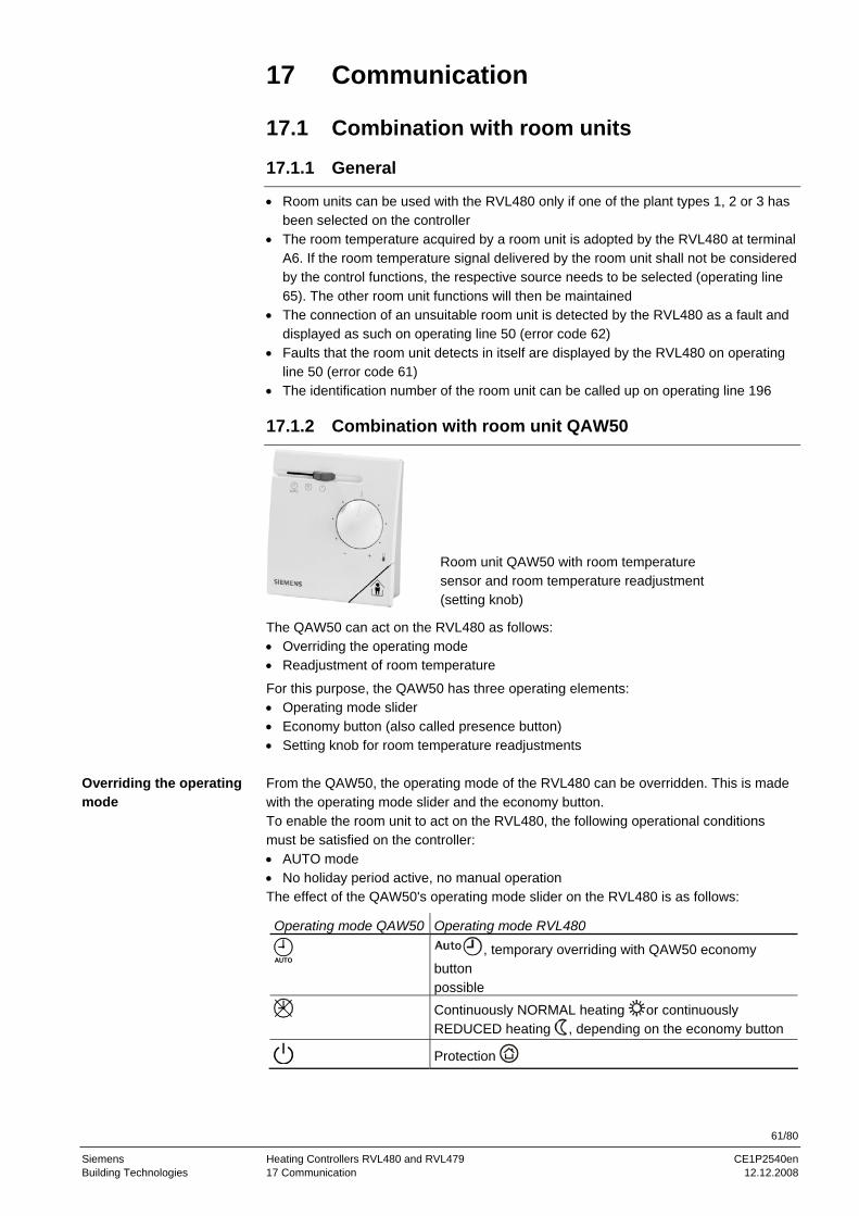
61/80
Siemens Heating Controllers RVL480 and RVL479 CE1P2540en Building Technologies 17 Communication 12.12.2008
17 Communication
17.1 Combination with room units
17.1.1 General
• Room units can be used with the RVL480 only if one of the plant types 1, 2 or 3 has been selected on the controller
• The room temperature acquired by a room unit is adopted by the RVL480 at terminal A6. If the room temperature signal delivered by the room unit shall not be considered by the control functions, the respective source needs to be selected (operating line 65). The other room unit functions will then be maintained
• The connection of an unsuitable room unit is detected by the RVL480 as a fault and displayed as such on operating line 50 (error code 62)
• Faults that the room unit detects in itself are displayed by the RVL480 on operating line 50 (error code 61)
• The identification number of the room unit can be called up on operating line 196
17.1.2 Combination with room unit QAW50
Room unit QAW50 with room temperature sensor and room temperature readjustment (setting knob)
The QAW50 can act on the RVL480 as follows: • Overriding the operating mode • Readjustment of room temperature
For this purpose, the QAW50 has three operating elements: • Operating mode slider • Economy button (also called presence button) • Setting knob for room temperature readjustments From the QAW50, the operating mode of the RVL480 can be overridden. This is made with the operating mode slider and the economy button. To enable the room unit to act on the RVL480, the following operational conditions must be satisfied on the controller: • AUTO mode • No holiday period active, no manual operation The effect of the QAW50's operating mode slider on the RVL480 is as follows:
Operating mode QAW50 Operating mode RVL480
, temporary overriding with QAW50 economy button possible
Continuously NORMAL heating or continuously REDUCED heating , depending on the economy button
Protection
Overriding the operating mode
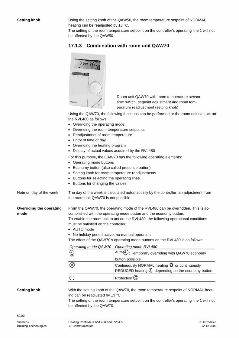
62/80
Siemens Heating Controllers RVL480 and RVL479 CE1P2540en Building Technologies 17 Communication 12.12.2008
Using the setting knob of the QAW50, the room temperature setpoint of NORMAL heating can be readjusted by ±3 °C. The setting of the room temperature setpoint on the controller's operating line 1 will not be affected by the QAW50.
17.1.3 Combination with room unit QAW70
Room unit QAW70 with room temperature sensor, time switch, setpoint adjustment and room tem-perature readjustment (setting knob)
Using the QAW70, the following functions can be performed or the room unit can act on the RVL480 as follows: • Overriding the operating mode • Overriding the room temperature setpoints • Readjustment of room temperature • Entry of time of day • Overriding the heating program • Display of actual values acquired by the RVL480
For this purpose, the QAW70 has the following operating elements: • Operating mode buttons • Economy button (also called presence button) • Setting knob for room temperature readjustments • Buttons for selecting the operating lines • Buttons for changing the values
The day of the week is calculated automatically by the controller; an adjustment from the room unit QAW70 is not possible. From the QAW70, the operating mode of the RVL480 can be overridden. This is ac-complished with the operating mode button and the economy button. To enable the room unit to act on the RVL480, the following operational conditions must be satisfied on the controller: • AUTO mode • No holiday period active, no manual operation The effect of the QAW70's operating mode buttons on the RVL480 is as follows:
Operating mode QAW70 Operating mode RVL480
; Temporary overriding with QAW70 economy button possible
Continuously NORMAL heating or continuously REDUCED heating , depending on the economy button
Protection
With the setting knob of the QAW70, the room temperature setpoint of NORMAL heat-ing can be readjusted by ±3 °C. The setting of the room temperature setpoint on the controller's operating line 1 will not be affected by the QAW70.
Setting knob
Note on day of the week
Overriding the operating mode
Setting knob

63/80
Siemens Heating Controllers RVL480 and RVL479 CE1P2540en Building Technologies 17 Communication 12.12.2008
If 1 (slave with no remote adjustment) is entered on operating line 178 (clock mode) of the RVL480, the time of day on the QAW70 cannot be changed.
Line on QAW70
Function, parameter Effect on RVL480, notes
1 Setpoint of NORMAL heating Changes operating line 1 on the RVL480
2 Setpoint of REDUCED heating Changes operating line 2 on the RVL480
3 Setpoint of d.h.w. temperature Not available on the RVL480
4 Weekday (entry of heating program)
Changes operating line 4 on the RVL480
5 First heating period, start of NORMAL heating
Changes operating line 5 on the RVL480
6 First heating period, start of REDUCED heating
Changes operating line 6 on the RVL480
7 Second heating period, start of NORMAL heating
Changes operating line 7 on the RVL480
8 Second heating period, start of RECUCED heating
Changes operating line 8 on the RVL480
9 Third heating period, start of NORMAL heating
Changes operating line 9 on the RVL480
10 Third heating period, start of REDUCED heating
Changes operating line 10 on the RVL480
11 Display of weekday 1…7 Cannot be adjusted (refer to subsection “6.2 Time of day and date”)
12 Entry time of day Changes operating line 38 on the RVL480
13 Display of d.h.w. temperature Not available on the RVL480
14 Display of boiler temperature Only with plant types 2 and 5
15 Display of flow temperature Only with plant types 1, 3, 4 and 6
16 Holidays RVL480 changes to protection mode
17 Reset to default values QAW70 default values are used
51 Bus address Bus address to be entered on the room unit 1
52 Identification room unit Display on operating line 196 of the RVL480
53 Operating lock on QAW70 No effect on RVL480
58 Type of setpoint display No effect on RVL480
For detailed information about the QAW70 room unit, refer to Installation Instructions 1637 (74 319 0173 0). If the RVL480 with a connected QAW70 is isolated from the mains network and then reconnected, the following parameters on the QAW70 will be overwritten with the set-tings made on the RVL480: • Time of day and weekday • Complete heating program • Room temperature setpoint of NORMAL heating • Room temperature setpoint of REDUCED heating This means that the RVL480 is always the data master.
Effect of the individual QAW70 operating lines on the RVL480
Note
Overriding the QAW70 entries from the RVL480

64/80
Siemens Heating Controllers RVL480 and RVL479 CE1P2540en Building Technologies 17 Communication 12.12.2008
17.2 Combination with SYNERGYR central unit OZW30
Based on the room temperatures of the individual apartments, the central unit OZW30 (software version 3.0 or higher) generates a load signal. This signal is passed on via LPB to the RVL480 where it produces an appropriate change of the flow temperature setpoint.
17.3 Communication with other devices
The RVL480 offers the following communication choices: • Signaling the heat demand of several RVL480 to the heat generating equipment • Exchange of locking and forced signals • Exchange of measured values such as outside temperature, return temperature and
flow temperature as well as clock signals • Controller RVL481 is not compatible with the RVL469; RVL479 is downward com-
patible • Exchange of fault status signals For detailed information about the communication via LPB, refer to the following docu-ments: • Data sheet N2030, "Basic System Data" • Data sheet N2032, "Basic Engineering Data"
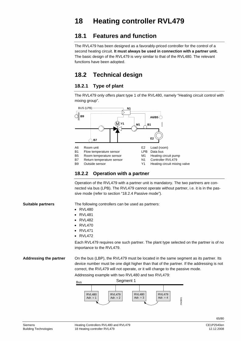
65/80
Siemens Heating Controllers RVL480 and RVL479 CE1P2540en Building Technologies 18 Heating controller RVL479 12.12.2008
18 Heating controller RVL479
18.1 Features and function
The RVL479 has been designed as a favorably-priced controller for the control of a second heating circuit. It must always be used in connection with a partner unit. The basic design of the RVL479 is very similar to that of the RVL480. The relevant functions have been adopted.
18.2 Technical design
18.2.1 Type of plant
The RVL479 only offers plant type 1 of the RVL480, namely “Heating circuit control with mixing group”.
B9 A6/B5
B7
2543
S01
E2
BUS (LPB) N1
B1M1Y1
A6 Room unit E2 Load (room) B1 Flow temperature sensor LPB Data bus B5 Room temperature sensor M1 Heating circuit pump B7 Return temperature sensor N1 Controller RVL479 B9 Outside sensor Y1 Heating circuit mixing valve
18.2.2 Operation with a partner
Operation of the RVL479 with a partner unit is mandatory. The two partners are con-nected via bus (LPB). The RVL479 cannot operate without partner, i.e. it is in the pas-sive mode (refer to section “18.2.4 Passive mode”). The following controllers can be used as partners: • RVL480 • RVL481 • RVL482 • RVL470 • RVL471 • RVL472
Each RVL479 requires one such partner. The plant type selected on the partner is of no importance to the RVL479. On the bus (LBP), the RVL479 must be located in the same segment as its partner. Its device number must be one digit higher than that of the partner. If the addressing is not correct, the RVL479 will not operate, or it will change to the passive mode. Addressing example with two RVL480 and two RVL479:
Segment 1
RVL480Adr. = 1
RVL479Adr. = 2
RVL480Adr. = 3
RVL479Adr. = 4
2543
B01
Bus
Suitable partners
Addressing the partner
66/80
Siemens Heating Controllers RVL480 and RVL479 CE1P2540en Building Technologies 18 Heating controller RVL479 12.12.2008
18.2.3 Handling errors
If two RVL479 have the same bus address, a fault message will be generated in both controllers and operating line 50 will display error code 82 (same bus address assigned several times). In that case, both RVL479 will change to the passive mode until the addresses have been correctly entered. If the partner is not correctly addressed, the RVL479 will not be able to establish a connection. The response is the same as if the partner was faulty. The RVL479 periodically prompts its partner on the bus. Depending on the reply given, the RVL479 will respond as follows:
Reply Response
The partner is correctly identi-fied (e.g. RVL480)
The RVL479 is switched to the active mode; it operates normally. A new prompt is made after 10 minutes
The identified partner is inad-missible (e.g. RVP3…)
The RVL479 changes to the passive mode. A new prompt is made after 1 minute
The RVL479 gets no reply from the partner (e.g. bus inter-rupted)
The RVL479 maintains its current operational status and makes a new prompt after 1 minute. After the third successive prompt with no reply, the RVL479 changes to the passive mode
After switching on power, the RVL479 will always be in the passive mode.
18.2.4 Passive mode
The passive mode of the RVL479 is defined as follows: • The outputs are switched as follows:
– Pump M1 = OFF – Mixing valve Y1 = CLOSED
• A fault message with error code 142 (missing partner) will be generated • Manual operation works normally • Operation and display work normally • Operation with the room unit works normally • On the bus (LPB), process signals and temperatures are exchanged the normal way
Wrong addressing
Missing or wrong partner

67/80
Siemens Heating Controllers RVL480 and RVL479 CE1P2540en Building Technologies 19 Handling 12.12.2008
19 Handling
19.1 Operation
19.1.1 General
1
10
2
311
6
45
7
8
9
12
13
2540
Z03
1 Operating mode buttons (selected button is lit) 2 Display (LCD) 3 Buttons for operating the display:
Prog = selection of operating line – + = adjustment of displayed value
4 Button for “Close heating circuit mixing valve” or burner stage 2 ON/OFF in manual operation 5 Button for “Open heating circuit mixing valve” in manual operation 6 Button for manual operation 7 LEDs for:
Manual operation / Heating circuit mixing valve opens / burner stage 1 ON / Heating circuit mixing valve closes / burner stage 2 ON
Pump runs 8 Sealing facility in the cover 9 Info button for the display of actual values 10 Setting slider for flow temperature setpoint at an outside temperature of –5 °C 11 Setting slider for flow temperature setpoint at an outside temperature of 15 °C 12 Setting knob for readjustment of room temperature 13 Fixing screw with sealing facility
2540
Z101 2
34
5
6
7
8
9
1 Display of fault status messages 2 Display of "Holiday program active" 3 Display of "ECO function active" 4 Display of "Bus power supply available" 5 Cursor for Info button (display of temperatures) 6 Display of temperatures, times, etc. 7 Display of current heating program 8 Display of operational level 9 Display of current operating line number
Operating elements
Display
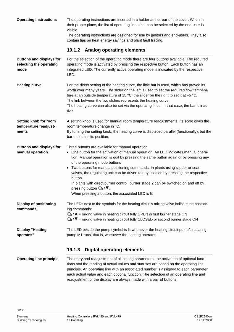
68/80
Siemens Heating Controllers RVL480 and RVL479 CE1P2540en Building Technologies 19 Handling 12.12.2008
The operating instructions are inserted in a holder at the rear of the cover. When in their proper place, the list of operating lines that can be selected by the end-user is visible. The operating instructions are designed for use by janitors and end-users. They also contain tips on heat energy savings and plant fault tracing.
19.1.2 Analog operating elements
For the selection of the operating mode there are four buttons available. The required operating mode is activated by pressing the respective button. Each button has an integrated LED. The currently active operating mode is indicated by the respective LED. For the direct setting of the heating curve, the little bar is used, which has proved its worth over many years. The slider on the left is used to set the required flow tempera-ture at an outside temperature of 15 °C, the slider on the right to set it at –5 °C. The link between the two sliders represents the heating curve. The heating curve can also be set via the operating lines. In that case, the bar is inac-tive. A setting knob is used for manual room temperature readjustments. Its scale gives the room temperature change in °C. By turning the setting knob, the heating curve is displaced parallel (functionally), but the bar maintains its position. Three buttons are available for manual operation: • One button for the activation of manual operation. An LED indicates manual opera-
tion. Manual operation is quit by pressing the same button again or by pressing any of the operating mode buttons
• Two buttons for manual positioning commands. In plants using slipper or seat valves, the regulating unit can be driven to any position by pressing the respective button. In plants with direct burner control, burner stage 2 can be switched on and off by pressing button / . When pressing a button, the associated LED is lit
The LEDs next to the symbols for the heating circuit's mixing valve indicate the position-ing commands:
/ = mixing valve in heating circuit fully OPEN or first burner stage ON / = mixing valve in heating circuit fully CLOSED or second burner stage ON
The LED beside the pump symbol is lit whenever the heating circuit pump/circulating pump M1 runs, that is, whenever the heating operates.
19.1.3 Digital operating elements
The entry and readjustment of all setting parameters, the activation of optional func-tions and the reading of actual values and statuses are based on the operating line principle. An operating line with an associated number is assigned to each parameter, each actual value and each optional function. The selection of an operating line and readjustment of the display are always made with a pair of buttons.
Operating instructions
Buttons and displays for selecting the operating mode
Heating curve
Setting knob for room temperature readjust-ments
Buttons and displays for manual operation
Display of positioning commands
Display "Heating operates"
Operating line principle

69/80
Siemens Heating Controllers RVL480 and RVL479 CE1P2540en Building Technologies 19 Handling 12.12.2008
To select and readjust setting values, the procedure is the following:
Buttons Procedure Effect
Press button Selection of the next lower operating line Line selection buttonsPress button Selection of the next higher operating line Press button Decrease of displayed value Setting buttons Press button Increase of displayed value
The value set will be adopted • when selecting the next operating line, that is, by pressing button or • by pressing the Info button • by pressing any of the operating mode buttons If the entry of --.- or --:-- is required, button or must be pressed until the required display appears. Then, the display maintains --.-. The operating lines are grouped as blocks. To reach a specific operating line of a block quickly, the other blocks can be skipped, so it is not necessary to select all the other lines one by one. This is accomplished by using two combinations of buttons:
Procedure Effect
Keep button depressed and push Selection of the next higher function block
Keep button depressed and push Selection of the next lower function block
The Info button is used to obtain basic information about the plant. Pressing this button, the cursor in the display is placed below the required symbol. The symbols have the following meaning: Symbol Display of
Flow or boiler temperature
Room temperature
Outside temperature
Time of day It is always the information selected last that is permanently shown in the display.
19.1.4 Setting levels and access rights
The operating lines are assigned to three different levels. Assignment and access are as follows:
Level Operating lines Access
End-user 1 to 50 Press or
Heating engineer 51 to 197 Press and for three seconds
Locking level 248 Press and together until appears; then, press, , and one by one
• The end-user can access all analog operating elements.
This means that he can select the operating mode, set the heating curve, readjust the room temperature with the setting knob, and activate manual operation. Also, he can access the setting level "End-user" on operating lines 1 to 50.
• The heating engineer can access all operating elements and operating lines
Buttons
Block skip function
Info button
Setting levels
Access rights
70/80
Siemens Heating Controllers RVL480 and RVL479 CE1P2540en Building Technologies 19 Handling 12.12.2008
19.2 Commissioning
19.2.1 Installation instructions
The RVL480 is supplied with installation instructions which give a detailed description of installation, wiring and commissioning with functional checks and settings. They are written for trained specialists. Each operating line has an empty field in which the se-lected value can be entered..
The installation instructions should not be thrown away after use but kept together with the plant documentation.
19.2.2 Operating lines
The most important work to be performed when commissioning the plant is entry of the required type of plant. This entry activates all functions and settings required for the relevant plant type. All operating lines contain field-proven and practice-oriented values. Codings, guide values, explanations, etc., are given in the installation instructions where required. Function block "Service functions and general settings" contains three operating lines that are especially suited for making functional checks: • Operating line 161 permits the simulation of an outside temperature • On operating line 162, each of the three output relays can be energized • On operating line 163, all actual sensor values can be called up • On operating line 164, the states of the H–x contacts can be called up If the display shows , the fault can be pinpointed via the error code on operating line 50.
19.3 Installation
19.3.1 Location
The ideal location for the controller is a dry room, such as the boiler room, but it can also be installed in a location which, from a climatic point of view, is unfavorable. Its degree of protection is IP42 to EN 60529 and is therefore protected against dripping water. The permissible ambient temperature is 0…50 °C. The RVL480 can be fitted as follows: • In a control panel (on the inner wall or on a top hat rail) • On a panel • In the control panel front • In the sloping front of a control desk
19.3.2 Mounting choices
The RVL480 can be mounted in three different ways: • Wall mounting: the base is secured to a flat wall with three screws • Rail mounting: the base is snapped on a top hat rail • Flush panel mounting: the base is fitted in a panel cutout measuring
138 × 138 mm (+1 mm / –0 mm)
Setting the operating line "Plant type"
Setting the other operat-ing lines
Operating lines for func-tional checks

71/80
Siemens Heating Controllers RVL480 and RVL479 CE1P2540en Building Technologies 19 Handling 12.12.2008
19.3.3 Wiring
• Local regulations for electrical installations must be complied with • Only qualified staff may carry out electrical installations • The cable lengths should be chosen such that there is sufficient space to open the
control panel door • Cable tension relief must be provided • The cables of the measuring circuits carry extra-low voltage • The cables from the controller to the regulating unit and the pump carry mains voltage • Sensor cables must not be run parallel to mains carrying cables for loads such as
actuator, pump, burner, etc. (insulation class II EN 60730)

72/80
Siemens Heating Controllers RVL480 and RVL479 CE1P2540en Building Technologies 20 Engineering 12.12.2008
20 Engineering
20.1 Connection terminals
1 2 3 4 5 6 7 8 9 10 11 12 13 14 15 16 17 18 19 20
1 2 3 4 5 6 7 8 9 10 11 12 13 14 15 16 17 18 19 20
2540
Z11
N L F1/F4
Y1/K4
F2/F5
Y2/K5 F3 Q1
DB MB A6 MD B9 B1 Ux B7 H1 H2 B5 B71 H4 H3M M M M
M
N
Base with terminals
20.1.1 Low voltage side
DB Data LPB MB Ground for LPB A6 PPS (point-to-point interface), connection of room unit MD Ground for PPS B9 Outside sensor B1 Flow or boiler temperature sensor M Ground for sensors, changeover contacts and signal outputs (4 times) Ux Heat demand output B7 Return temperature sensor H1 Changeover contact "Operating mode" H2 Changeover contact for flow temperature setpoint B5 Room temperature sensor B71 Return temperature sensor (primary circuit) H4 Minimum stroke limitation (Ymin contact) H3 Contact for locking the district heat parameters
The low voltage side carries one auxiliary terminal (M).
20.1.2 Mains voltage side
N Neutral AC 230 V L Live AC 230 V F1/F4 Input for Y1/K4 Y1/K4 Heating circuit mixing valve OPEN / first burner stage ON F2/F5 Input for Y2/K5 Y2/K5 Heating circuit mixing valve CLOSE / second burner stage ON F3 Input for Q1 Q1 Heating circuit pump / circulating pump
The mains voltage side carries two auxiliary terminals (N and ).
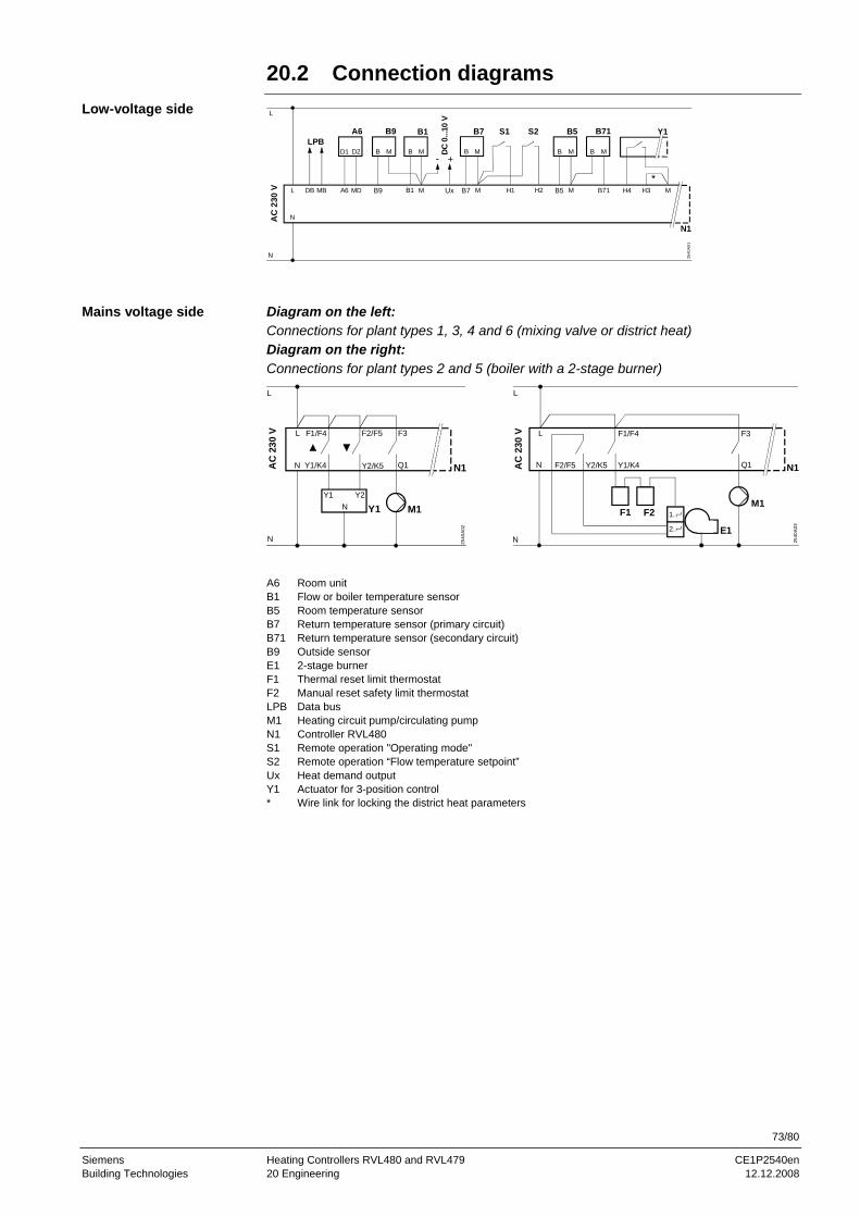
73/80
Siemens Heating Controllers RVL480 and RVL479 CE1P2540en Building Technologies 20 Engineering 12.12.2008
20.2 Connection diagrams
AC
230
V B9
D2
L DB MB A6 MD B1 M
N
LPBD1 MB MB
A6 B9 B1
B7 B5M H1 H2 M B71 H4 H3 M
MB MB MB
B7 S1 S2 B5 B71 Y1
2540
A01
N1
Ux
DC 0
...10
V
+-
L
N Diagram on the left: Connections for plant types 1, 3, 4 and 6 (mixing valve or district heat) Diagram on the right: Connections for plant types 2 and 5 (boiler with a 2-stage burner)
AC
230
V
2540
A02
L
N
F1/F4 F2/F5 F3
Y1/K4 Y2/K5 Q1
Y1 Y2N
N1
M1Y1
L
N
AC
230
V1.
2.
F1 F2
2540
A03
L F1/F4
F2/F5
F3
N Y1/K4Y2/K5 Q1
E1
M1
N1
L
N
A6 Room unit B1 Flow or boiler temperature sensor B5 Room temperature sensor B7 Return temperature sensor (primary circuit) B71 Return temperature sensor (secondary circuit) B9 Outside sensor E1 2-stage burner F1 Thermal reset limit thermostat F2 Manual reset safety limit thermostat LPB Data bus M1 Heating circuit pump/circulating pump N1 Controller RVL480 S1 Remote operation "Operating mode" S2 Remote operation “Flow temperature setpoint” Ux Heat demand output Y1 Actuator for 3-position control * Wire link for locking the district heat parameters
Low-voltage side
Mains voltage side

74/80
Siemens Heating Controllers RVL480 and RVL479 CE1P2540en Building Technologies 21 Mechanical design 12.12.2008
21 Mechanical design 21.1 Basic design
The RVL480 is comprised of controller insert, which accommodates the electronics, the power section, the output relays and – on the front – all operating elements, and the base, which carries the connection terminals. The operating elements are located behind a lockable transparent cover. On the inner side of the cover, there is a holder in which the operating instructions can be inserted. All values are read in the display (LCD) featuring background lighting. The cover can be sealed. The RVL480 has standard overall dimensions (144 ×144 mm). It can be fitted in three different ways: • Wall mounting • Rail mounting • Flush panel mounting Whichever mounting method is chosen, the base must always be mounted and wired first. To ensure the orientation will be correct, the upper side of both the base and the controller housing carry the marking TOP. Both the top and the bottom side of the base have 5 knockout holes for cable entries, and there are ten knockout holes in the floor. The controller insert is placed in the base. The controller insert has two fixing screws with rotating levels. If, after insertion of the controller insert, one of the screws is tight-ened, the lever engages in an opening in the base. When the screws are further tight-ened (alternately), the controller pulls itself into the base so that it is secured. The fixing screw at the bottom can be sealed. The grommet (attached to the key ring) must be inserted in the screw hole, a safety wire introduced through the two lugs, and then sealed.
21.2 Dimensions
139951.5 (42.5)
18
16.4
26 26 26 26
15.3
144
144
144
3672
106108
50 36293539
39
106
144.5
max. 3
IEC 61554 - 144 × 144
35 ±
0.3
EN 60715
max. 5
M16
EN 50262
22
max. 8
2540
M01
138+10
138+1 0
Dimensions in mm

75/80
Siemens Heating Controllers RVL480 and RVL479 CE1P2540en Building Technologies 22 Technical data 12.12.2008
22 Technical data
Rated operating voltage AC 230 V (±10 %) Frequency 50 Hz Power consumption (no external load) max. 7 VA Supply line fusing 10 A Switching capacity AC 24…230 V Switching current Y1/K4, Y2/K5, Q1 AC 0.02…2 (2) A Rated current of ignition transformer max.1 A (max. 30 s) Switch-on current of ignition transformer max.10 A (max. 10 ms) Copper cable 0.6 mm ∅ 20 m Copper cable 0.5 mm2 50 m Copper cable 1.0 mm2 80 m Copper cable 1.5 mm2 120 m Screw terminals for wire section up to 2.5 mm2 Bus protocol / type LPB Bus loading characteristic E 6 Backup of controller clock 12 h
-conformance to EMC directive – Immunity – Emissions Low voltage directive – Safety
2004/108/EC – EN 61000-6-1 / -2 – EN 61000-6-3 / -4 2006/95/EC – EN 60730-1 / EN 60730-2-9
Safety class II to EN 60730 Degree of protection (cover closed) IP42 to EN 60529 Degree of contamination 2 to EN 60730 refer to ”Dimensions“ Unit (net) 1.1 kg Controller insert Light grey RAL 7035 Terminal base Pigeon blue RAL 5014 Operation
EN 60721-3-3 Transport EN 60721-3-2
Storage EN 60721-3-1
Climatic conditions class 3K5 class 2K3 class 1K3 Temperature 0…+50 °C –25…+70 °C –20…+65 °CHumidity <95 % r.h.
(non-condensing) <95 % r.h. <95 % r.h.
(non-condensing)Mechanical conditions class 3M2 class 2M2 class 1M2 Use above sea level max. 3000 m above sea level
Power supply
Output relays
Permissible cable lengths to sensors and room unit
Connection terminals
Communication by wire
Backup
Standards
Protective data
Dimensions
Weight
Colors
Environmental conditions
76/80
Building Technologies Heating Controllers RVL480 and RVL479 CE1P2540en Index 12.12.2008
Index
2 2-position control .......................................................38 2-position controller ...................................................37
3 3-position control .................................................35, 36
A access rights .............................................................69 acquisition of measured values .................................18 address......................................................................56 addressing of devices................................................56 addressing RVL479...................................................65 analog operating elements ........................................68 attenuated outside temperature ................................25 automatic mode.........................................................16 auxiliary terminals......................................................72 averaging...................................................................18
B bar .............................................................................32 base...........................................................................74 basic information .......................................................69 basic setting heating curve........................................32 block skip function .....................................................69 boiler operating mode................................................17 boiler operating modes..............................................37 boiler overtemperatures ............................................41 boiler startup..............................................................40 boost heating.............................................................30 bridging terminals H1–M ...........................................53 bridging terminals H2–M ...........................................58 bridging terminals H3–M ...........................................60 bridging terminals H4–M ...........................................47 brief description ...........................................................9 building time constant................................................25 buildings ....................................................................11 burner cycling protection ...........................................38 bus loading characteristic..........................................57 bus power supply ......................................................57 buttons for manual operation.....................................68
C central unit OZW30 ...................................................64 changeover winter- / summertime .............................54 combination with room unit QAW50 ..........................61 combination with room unit QAW70 ..........................62 combination with SYNERGYR central unit OZW30 ......................................................................64 commissioning...........................................................70 communication ..........................................................64 composite outside temperature .................................25
connection diagrams ................................................ 73 connection terminals................................................. 72 contact H1 ................................................................ 53 contact H2 ................................................................ 58 continuous NORMAL heating ................................... 16 continuous REDUCED heating................................. 16 control with a 2-stage burner .................................... 39 control with a single-stage burner............................. 38 controller insert ......................................................... 74 critical locking signals ............................................... 54
D date........................................................................... 23 demand-compensated control .................................. 34 differential of return temperature .............................. 46 digital operating elements......................................... 68 dimensions ............................................................... 74 display ...................................................................... 67 display "Heating operates" ....................................... 68 display functions ....................................................... 48 display of current setpoints....................................... 33 display of positioning commands.............................. 68 displays for manual operation................................... 68 district heat connection............................................. 45 DRT .......................................................................... 46
E ECO function ............................................................ 25 electronics ................................................................ 74 engineering............................................................... 72 entries for LPB.......................................................... 55 entry of the type of plant ........................................... 24 excess mixing valve temperature ............................. 36
F flow alarm ................................................................. 52 flow and boiler temperature ...................................... 18 flue gas condensation............................................... 43 forced signal ............................................................. 41 frost protection for the boiler..................................... 40 frost protection for the plant...................................... 52 function ..................................................................... 48 function block 3-position controller ........................... 35 function block Boiler ................................................. 37 function block Contact H2......................................... 58 function block Contact H2 and general displays....... 59 function block District heat........................................ 45 function block End-user 1 ......................................... 21 function block End-user 2 ......................................... 23 function block Locking functions............................... 60 function block Minimum limitation of return temperature .............................................................. 43 function block Plant type........................................... 24
77/80
Siemens Heating Controllers RVL480 and RVL479 CE1P2540en Building Technologies Index 12.12.2008
function block Setpoint of return temperature limitation....................................................................43 function block Space heating ....................................25 function blocks ..........................................................13
G gain factor for the room temperature influence .........31 gain of locking signal.................................................54 generation of setpoint ...............................................34
H handling ....................................................................67 handling of faults.......................................................18 H-contacts.................................................................51 heat demand output ..................................................57 heat storage capacity................................................25 heating curve ................................................32, 49, 68 heating curve's deflection..........................................32 heating limits .............................................................26 heating program........................................................21 heating systems ........................................................11 holiday program ........................................................22 hours run counter......................................................59
I identification number of room unit.............................59 indication of faults .....................................................23 info button .................................................................69 installation instructions..............................................70 integral action time....................................................47 interconnected plants................................................36
K key features ................................................................9
L limitation of return temperature differential ...............46 limitations of the flow temperature ............................45 little bar .....................................................................32 location......................................................................70 locked on the software side ......................................60 locking.......................................................................60 locking functions .......................................................60 locking of pulses .......................................................36 locking the settings for district heat...........................60 locking the settings on the hardware side.................60 locking the settings on the software side ..................60 LPB ...........................................................................55
M manual operation ......................................................17 manual overriding of flow temperature......................58 manual overriding of operating mode .......................53 master clock..............................................................55 maximum limitation of boiler temperature .................37 maximum limitation of flow temperature ...................35
maximum limitation of primary return temperature...............................................................45 maximum limitation of return temperature differential..................................................................46 maximum limitation of room temperature..................31 mechanical design ....................................................74 minimum burner running time ...................................38 minimum limitation of boiler temperature ..................38 minimum limitation of flow temperature.....................35 minimum limitation of stroke......................................47 mounting choices ......................................................70
N NORMAL heating ......................................................16
O operating elements....................................................67 operating instructions ................................................68 operating line principle ..............................................68 operating modes .......................................................16 operation ...................................................................67 operational level ........................................................17 operational status......................................................17 optimization ...............................................................27 optimum start control.................................................29 optimum stop control .................................................29 outside temperature ..................................................19
P parallel displacement of heating curve......................33 partner unit RVL479 ..................................................65 periodic pump run .....................................................54 plant type and operating mode..................................17 plant types.................................................................13 plant types.................................................................14 primary return temperature .......................................19 product documentation..............................................10 protection ..................................................................17 protection against boiler overtemperatures...............41 protective boiler startup.............................................40 pump kick ..................................................................54 pump overrun ............................................................53 pump overrun time ....................................................41
Q quick setback ............................................................29
R REDUCED heating....................................................16 relay test....................................................................50 release limit ...............................................................39 reset limit ...................................................................39 room model ...............................................................18 room model temperature...........................................28 room temperature......................................................18 room temperature deviations ....................................31
78/80
Siemens Heating Controllers RVL480 and RVL479 CE1P2540en Building Technologies Index 12.12.2008
room temperature influence ......................................31 room temperature setpoint boost ..............................30 room unit QAW50......................................................61 room unit QAW70......................................................62 room units that cannot be used .................................59 RVL479 .....................................................................65
S safety functions .........................................................37 sealing .......................................................................74 secondary return temperature ...................................20 selection of operating mode ......................................68 setpoint increase .......................................................35 setpoint of return temperature limitation....................43 setpoints ....................................................................21 setpoints and measured values of sensors ...............50 setting knob for room temperature readjustments............................................................68 setting levels..............................................................69 shifting compensation................................................46 simulation of outside temperature .............................50 software version ........................................................59 source of outside temperature...................................56 source of time of day .................................................55
suitable actuators ..................................................... 10 suitable room units ................................................... 10 suitable sensors.......................................................... 9 summertime.............................................................. 54 suppression of hydraulic creep................................. 47 switching times ......................................................... 21
T terminate the relay test ............................................. 50 terminate the simulation ........................................... 50 time of day ................................................................ 23
U uncritical locking signals ........................................... 54
W weather-compensated control .................................. 34 winter- / summertime changeover ............................ 54 wintertime ................................................................. 54
Y yearly clock............................................................... 23 Ymin function............................................................ 47

79/80
Siemens Heating Controllers RVL480 and RVL479 CE1P2540en Building Technologies Index 12.12.2008

80/80
Siemens Heating Controllers RVL480 and RVL479 CE1P2540en Building Technologies 12.12.2008
Siemens Switzerland Ltd Building Technologies Division International Headquarters Gubelstrasse 22 CH – 6301 Zug Tel. +41 41 724 24 24 Fax +41 41 724 35 22 www.sbt.siemens.com
© 2008 Siemens Switzerland LtdSubject to alteration


