52
Heavy-Duty Fan Drive Maintenance Training Manual
Heavy-DutyFan Drive Maintenance
Training Manual


322540
Table of Contents
INTRODUCTION ................................................................................................................................ 4
LESSON 1: Fan Drive Operation ...................................................................................................... 5
LESSON 2: Heavy Duty Fan Drives .................................................................................................. 6
LESSON 3: Fan Drive Control System ............................................................................................ 10REVIEW QUESTIONS: Fan Drive Control Systems .......................................................................... 19LAB ACTIVITY: Fan Drive Components ......................................................................................... 21
LESSON 4: Preventive Maintenance (PM) ..................................................................................... 23REVIEW QUESTIONS: Preventive Maintenance ............................................................................... 25
LESSON 5: Horton Fan Drive Components .................................................................................... 27
LESSON 6: Corrective Maintenance ............................................................................................... 30REVIEW QUESTIONS: Corrective Maintenance ............................................................................... 34
FINAL TEST: Heavy Duty Fan Drive Maintenance .......................................................................... 35
APPENDIX A: Preventive Maintenance Check List 10,000 Miles [16,000 Km] .............................. 41
APPENDIX B: Preventive Maintenance Check List 25,000 Miles [40,000 Km] .............................. 42
APPENDIX C: Review Question Answers ....................................................................................... 44

4 22540
Introduction
This student manual for the technical course, Heavy-Duty Fan Drive Maintenance, is designed to trainheavy-duty diesel technicians how to perform preventive and corrective maintenance on Hortonheavy-duty fan drives.
This guide may be used in the classroom with an instructor or in a self-study mode. After completionof this course, take the Final Test at the end of this student manual. Mail your Final Test to the follow-ing address to receive a Certified Horton Technician toolbox sticker and a Horton Certificate ofAchievement:
Horton, Inc.2565 Walnut St.
Roseville, MN 55113, USAPhone: +1 (651) 361-6400
Toll-free: +1 (800)-621-1320Fax: +1 (651) 361-6801
Web site: www.hortonww.come-mail: [email protected]
In accordance with Horton’s established policy of constant product improvement, the specifications contained in this manual are subject to changewithout notice and are based on the latest information available at the time of printing.
522540
LESSON 1: Fan Drive Operation Objectives• Recognize the purposeand advantages of a fandrive.
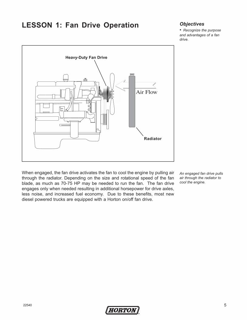
Heavy-Duty Fan Drive
Radiator
An engaged fan drive pullsair through the radiator tocool the engine.
When engaged, the fan drive activates the fan to cool the engine by pulling airthrough the radiator. Depending on the size and rotational speed of the fanblade, as much as 70-75 HP may be needed to run the fan. The fan driveengages only when needed resulting in additional horsepower for drive axles,less noise, and increased fuel economy. Due to these benefits, most newdiesel powered trucks are equipped with a Horton on/off fan drive.

6 22540
With more than 50 years of industry experience, Horton is a premier world-wide provider of the highest quality truck components. Horton suppliesseveral different models of heavy-duty fan drives.
Objectives• Recognize the
different models of Hortonheavy-duty fan drives
• Describe the HortonSystem Sentry® feature
9 “ [22.86 cm] singleplate fan drives arepainted gray.
9 “ Single PlateThe 9" [22.86 cm] single plate is an older stylefan drive (rarely supplied on new trucks) with alarger air chamber than other Horton fan drives.
Original SThe S model fan drive has a drive plate that is7.5 “ [ 19.05 cm] in diameter. An original Smodel fan drive has a smooth Piston FrictionDisc (PFD), whereas the newer model with Sys-tem Sentry® has three large bosses on the PFD.
Original HT/SThe HT/S model fan drive has a drive platethat is 9.5" [24.13 cm] in diameter. The origi-nal HT/S model fan drive has a smooth PFDwhile an Advantage model with System Sentryhas three large bosses on the PFD.
S and HT/S AdvantageThe S and HT/S Advantage are heavy duty fandrives, equipped to handle the frequent on/offcycles common in severe-duty trucking appli-cations. Both fan drives include the SystemSentry feature along with a plastic air cartridgeand improved hub assembly.
S and HT/S fan Drivesare painted blue andmay be upgraded byinstalling an AdvantageSuper Kit.
S and HT/S Advantagefan drives are paintedgun-metal blue.
Advantage Reman fandrives are paintedmaroon.
LESSON 2: Heavy-Duty Fan Drives
722540
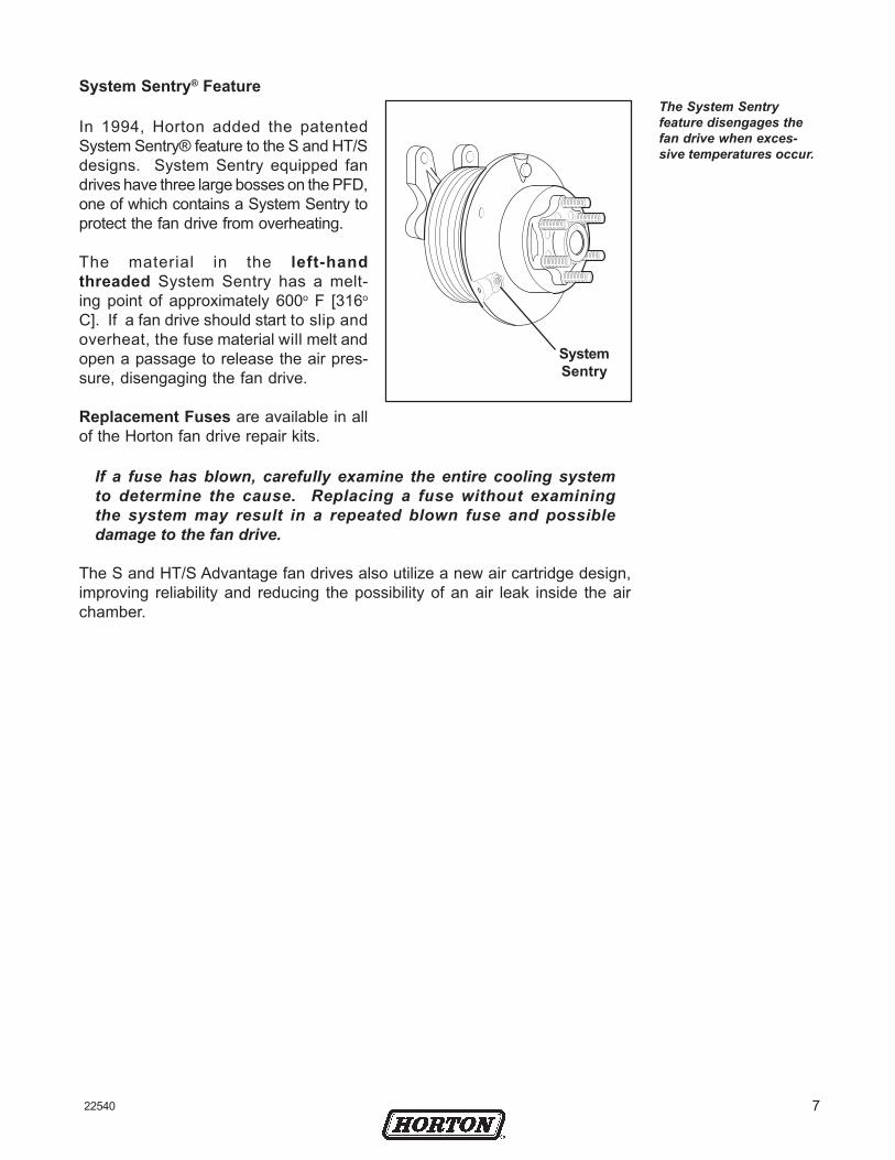
System Sentry® Feature
In 1994, Horton added the patentedSystem Sentry® feature to the S and HT/Sdesigns. System Sentry equipped fandrives have three large bosses on the PFD,one of which contains a System Sentry toprotect the fan drive from overheating.
The material in the left-handthreaded System Sentry has a melt-ing point of approximately 600o F [316o
C]. If a fan drive should start to slip andoverheat, the fuse material will melt andopen a passage to release the air pres-sure, disengaging the fan drive.
Replacement Fuses are available in allof the Horton fan drive repair kits.
If a fuse has blown, carefully examine the entire cooling systemto determine the cause. Replacing a fuse without examiningthe system may result in a repeated blown fuse and possibledamage to the fan drive.
The S and HT/S Advantage fan drives also utilize a new air cartridge design,improving reliability and reducing the possibility of an air leak inside the airchamber.
SystemSentry
The System Sentryfeature disengages thefan drive when exces-sive temperatures occur.

8 22540
Troubleshooting the fan driveand controls should be donepromptly to locate the prob-lem which caused the Sys-tem Sentry® release of thefan drive. First locate andremove anything that may bean obstruction to the fanblade. Check the fan drivefor leaks. If no leaks arefound, check the solenoidand controls.
Horton fan drives aredesigned to permitcontinued operation inthe event of a fan driveair source or electricalcontrol system malfunc-tion.
In the event of a malfunction, turn engine off. Visually check the SystemSentry for signs of melting.
• If for any reason excessive heat is building up in the fan drive, theSystem Sentry will release and create an air leak. This shuts down thesystem to prevent any further damage.
• Your System Sentry may have an Allen head or a Torx head. A Torxwrench will work in the removal and installation of either System Sentry.
When replacing the System Sentry, be sure to loosen it in the correctdirection. It is a left-hand thread and needs to be turned clockwise forremoval.
CounterBalance
System Sentry®
Allen HeadSystem Sentry®
Piston FrictionDisc
Torx HeadSystem Sentry®
WARNINGOnly use a Horton System Sentry as a replacement. The Piston FrictionDisc is balanced and anything other than the Horton System Sentry willupset the balance.
922540
Install the new System Sentry®. Troubleshoot and correct the failedsystem component(s) as soon as possible.
CAUTIONFailure to troubleshoot may result in reoccuring System Sentry releases.
Lock Up Bolt Installation
• In the event your System Sentry cannot be replaced or youcannot immediately troubleshoot the cooling system, the lock up bolts canbe used as an alternative option.
Horton fan drives are designed to permit continued operation in theevent of a fan drive air source or electrical control system malfunction.
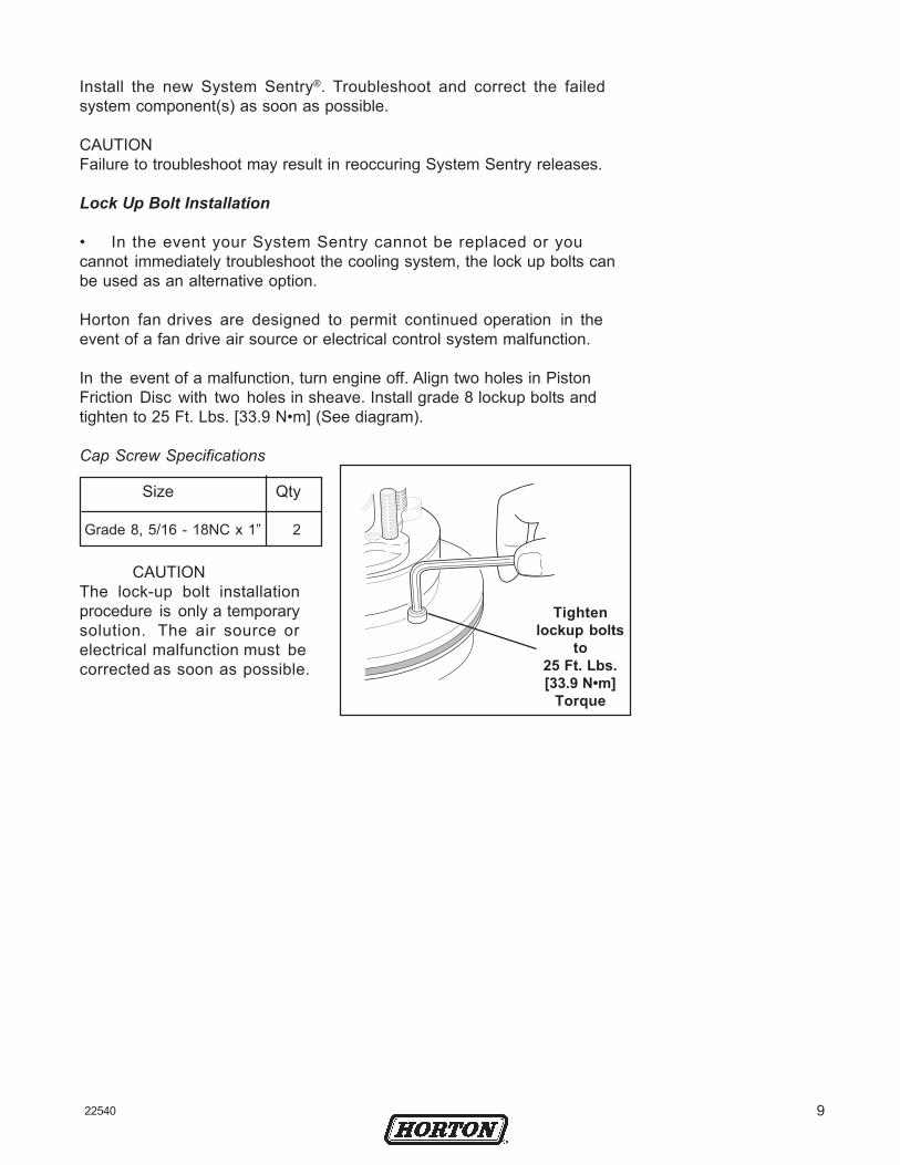
In the event of a malfunction, turn engine off. Align two holes in PistonFriction Disc with two holes in sheave. Install grade 8 lockup bolts andtighten to 25 Ft. Lbs. [33.9 N•m] (See diagram).
Cap Screw Specifications
CAUTIONThe lock-up bolt installationprocedure is only a temporarysolution. The air source orelectrical malfunction must becorrected as soon as possible.
Tightenlockup bolts
to25 Ft. Lbs.[33.9 N•m]
Torque
Size Qty
Grade 8, 5/16 - 18NC x 1” 2

10 22540
Depicted is an illustration of an independent fan drive control system. Theelectrically controlled solenoid valve engages and disengages the fan drive byregulating its air pressure on and off. The electrical circuit to the solenoidvalve contains three switches:
• a thermal switch sensing the engine coolant temperature.
• a refrigerant pressure switch in the truck’s air conditioning system.
• an optional manual override switch located on the truck’s dashboard.
Any of these three switches may activate the solenoid and engage the fan drive.
EXAMPLE. When the engine coolant temperature rises above thethermal switch’s set point, the thermal switch will activate the sole-noid valve, which will in turn send air pressure from the truck’s airreservoir to the fan drive and engage the fan.
Most newer trucks have an Electronic Control Module (ECM) – a smallcomputer that monitors and controls all engine operations, including thefan drive. If a truck uses an ECM, there is no direct connection between thesensors and fan drive solenoid valve. Information from sensors and switchesis fed into the ECM which in turn controls the solenoid valve.
To ignition
Objectives• describe the
components of a fan driveelectrical control system
• determine the correctair inlet port for a normallyopen and normally closedsolenoid valve
• describe the basicoperation of normallyopen, normally closed, andthe electronic controlmodule (ECM) and howthey control the electricalcontrol system
• determine if a truck’sfan drive electrical controlsystem is wired normally-open, normally-closed, orconnected to an ECM
LESSON 3: Fan Drive Control System
Solenoid Valve
Air Supply
Air Filter
A/C Refrigerant Pressure Switch
Thermal Switch
Manual Override Switch

1122540
Trucks not using an ECM usually have two sensors to auto-matically turn the fan on and off. First is the engine coolantthermal switch and second the air conditioning refriger-ant pressure switch.
The engine coolant thermal switch is mounted in thewater jacket on the engine.
• In a normally-open thermal switch, the electrical contacts are open whenthe temperature is below the set point and closed when the tempera-ture is above the set point.
• In a normally-closed thermal switch, the electrical contacts areclosed when the temperature is below the set point and open whenthe temperature is above the set point.
The refrigerant pressure switch is installed in the highpressure line of the cab’s air conditioning system. Whenthe air conditioner is running, heat removed from theair is absorbed by the refrigerant (e.g., freon, R-12 andR-134a). As the refrigerant heats, pressure builds in theair conditioner high pressure line until the refrigerantpressure reaches the switch’s set point. The switch thensends a signal to the solenoid valve to engage the fan drive.The fan pulls air through the air conditioner condenser coils,which cools the condenser/refrigerant and reduces refriger-ant pressure.
Some trucks have an air filterin the supply line going intothe solenoid valve. As shown,the Horton air filter connectsdirectly to the solenoid valveinlet port. The air filter con-tains an element to remove dirtfrom the compressed air beforeit enters the solenoid valve. Adrain valve at the bottom ofthe filter provides a check forexcessive contaminants. Drain the truck’s air
system prior to air filterremoval. The filter iseasily removed forcleaning by unscrewingthe bowl from the bottomof the assembly, thenunscrewing the filterelement.
Sensors
Drain Valve
Air Filter
To solenoidvalve inlet port
Truck Air in
Air Filter
Thermal switch resetpoint is usually 7oF[3.9oC] below the setpoint. Truck designerswill typically specify athermal switch with a setpoint 10-15o F [5.6-8.3o
C] higher than the fullyopen temperature of theengine thermostat.
Air conditioning refriger-ant pressure switchesare available as eithernormally-open ornormally-closed.
IN

12 22540
The solenoid valve is the heart of thefan drive control system, opening andclosing to regulate the air flow to thefan drive. The solenoid valve is a 3-way valve having two inlet and one out-let ports. Air pressure from the truck’sair system is fed into one of the inletports and the outlet port is connectedto the fan drive. The valve has a 3/64"[1.19 mm] orifice to regulate the volumeof air and ensure smooth engagementand disengagement of the fan drive.
Turning the solenoid electric current onand off causes a plunger inside the valve to move up and down. The plungerconnects the valve outlet port to one of the two inlet ports:
• the normally-open port when the electric current is off.• the normally-closed port when the electric current is on.
EXAMPLE. Normal can be expressed as the state the solenoid valvewould be in if it was completely disconnected and in your hand - thesolenoid would be de-energized, the normally-open port would beopen to the outlet port, and the normally-closed port would be closedto the outlet port.
The valve outlet port is always connected to the fan drive. Depending on thetruck’s electrical control circuits, the air supply may be connected to either thenormally-open or the normally-closed port. The port not connected to the airsupply will exhaust air from the fan drive when it disengages.
Various adapters and fittings are available to permit the solenoid valve tobe plumbed either normally-open or normally-closed (i.e., the air supplymay be connected to either inlet port). These fittings also permit thesolenoid valve to be installed with or without an air filter.
Remote mounting the solenoid valve off of the engine will minimize the valve’sexposure to excessive heat, vibration, and contaminants. The mounting loca-tion of the solenoid should be both functional and free of excessive heat, vibra-tion, and contaminants. A solenoid valve mounted off of the engine will pro-long the life of the solenoid and ensure proper fan drive operation.
Normal (as in normally-open or normally-closed)refers to the state of thesolenoid valve when it isrelaxed or de-energized.
N.O. Inlet Port/NC Exhaust Port
Air Outlet PortTo Fan Drive
N.C. Inlet Port/N.O. Exhaust
Port
Solenoid Valve
The solenoid valve iscontrolled by electricityand is available for 12and 24 volt electricalsystems.
1322540
The electrical wiring that controls the fan drive varies from truck to truck, butgenerally will be one of three types:
• normally-open
• normally-closed
• ECM controlled
Manufacturers that tend to have normally-closed electrical controls onnon-ECM engines include:
Blue BirdGMCMackFordNavistar/InternationalWhite GMC
Manufacturers that tend to have normally-open electrical controls onnon-ECM engines include:
FreightlinerMackWestern StarKenworthVolvoPeterbilt
Electrical Control Systems
The fan drive electrical control system may be normally-open ornormally-closed, and the solenoid valve may be plumbed normally-openor normally-closed. Horton fan drives are plumbed as follows:
• on trucks with a normally-open electrical system, connect theair supply to the solenoid valve’s normally-closed port.
• on trucks with a normally-closed electrical system, connect theair supply to the solenoid valve’s normally-open port.
Also, when referring to normally-open electrical systems, the reference isto electrical; when referring to normally-open valves, reference is to thepneumatics of the valve.

14 22540
The following schematic diagram is of a normally-open electrical controlsystem for a fan drive-when all switches are below their set points, the electri-cal circuit to the solenoid valve is open.
In such a system, all electrical switches are wired in parallel. Electricityfrom the 12 volt supply can take any one of the three parallel paths toreach the solenoid valve.
All three switches are shown in their normal state-open. When all switchesare open, no electricity flows to the solenoid valve and the solenoid is de-energized. The plunger inside the solenoid valve connects the outlet portto the normally-open port and blocks air pressure from going to the fan drive.The fan drive disengages and the fan is idle.
When one of the electrical switches closes, electricity flows through theswitch and energizes the solenoid valve. The plunger inside the solenoidvalve moves to connect the outlet port to the normally-closed inlet port.Air pressure flows through the valve to the fan drive, engaging the fan driveand causing the fan blade to turn.
In a system wired inparallel, electricity fromthe supply can take anyof the parallel paths toreach the valve.
Air Supply
Normally-Open Electrical Controls
NC
N O
SolenoidValve
ThermalSwitch(NO)
A/CPressure
Switch (NO)
ManualOverride
Switch (NO)+12 Volts
OUT
EXAMPLE. The engine coolant temperature rises abovethe thermal switch’s set point. The normally-open thermalswitch closes causing electricity to flow through the thermalswitch and energizing the solenoid valve. The solenoid valveplunger moves to connect the outlet port to the normally-closed inlet port. Air pressure flows through the valve toengage the fan drive, turning the fan blade.

1522540
The following schematic diagram is of a normally-closed electrical con-trol system for a fan drive-when all switches are below their set points, theelectrical circuit to the solenoid valve is closed.
In such a system, all electrical switches are wired in series. Electricityfrom the 12 volt supply must flow through all three switches before itreaches the solenoid valve.
All three switches are shown in their normal state-closed. When allswitches are closed, electricity flows to the solenoid valve and the sole-noid is energized. The plunger inside the solenoid valve connects theoutlet port to the normally-closed inlet port and blocks air pressure fromgoing to the fan drive. The fan drive disengages and the fan is idle.
When one of the electrical switches opens, the electrical current is bro-ken. The solenoid valve de-energizes. The plunger inside the solenoidvalve moves to connect the outlet port to the normally-open inlet port.Air pressure flows through the valve to the fan drive, engaging the fan driveand causing the fan blade to turn.
In a system wired inseries, electricity fromthe supply must flowthrough all switches toreach the valve.
ThermalSwitch (NC)
Normally-Closed Electrical Controls
SolenoidValve NC
N O
Air Supply+12 Volts
Manual OverrideSwitch (NC)
A/C PressureSwitch (NC)
EXAMPLE. The engine coolant temperature rises abovethe thermal switch’s set point. The normally-closed ther-mal switch opens, causing a break in the electrical currentand de-energizing the solenoid valve. The solenoid valveplunger moves to connect the outlet port to the normally-open inlet port. Air pressure flows through the valve toengage the fan drive, turning the fan blade.

16 22540
• Electrical switches are wiredin parallel.
• Air supply plumbed tosolenoid’s normally-closedport (the side port).
• Test fan drive by installing ajumper wire across a sensor.
• Manual Override Switch (ifequipped).
The following summa-rizes the normally-openand normally-closedelectrical systems forcontrolling an airengaged fan drive.
Normally-Open Electrical System with Normally-Closed Pneumatics
• Electrical switches are wiredin series.
• Air supply plumbed tosolenoid’s normally-openport (the end port).
• Test fan drive by disconnecting a wire from a sensor.
• Manual Override Switch (ifequipped).
Air Supply in
All switches openSolenoid de-energized
Drive disengaged
Any switch closedSolenoid energized
Drive engaged
Normally-Closed Electrical System with Normally-Open Pneumatics
All switches closedSolenoid energizedDrive disengaged
Any switch openSolenoid de-energized
Drive engaged
To FanDrive
Exhaust
Normally-Closed Port
Air Supply in
To Fan DriveExhaust
Normally-Open Port
Normally Open Electrical System
Elbow
Normally Closed Electrical System
2 1
2 1

1722540
ELECTRIC CONTROL MODULE (ECM) CONTROL
Engine manufacturers include Electronic Control Modules (ECMS) in theirnew designs to control the engine, transmission, and other criticaloperations to improve engine performance, reliability, and fuel efficiency.
An ECM is essentially a digital computer, containing a microprocessor,random-access-memory (RAM), and read-only-memory (ROM). The ROMcontains the computer’s program. Design engineers can change a truck’scontrol system and engine performance simply by changing the ECM’scomputer program.
As shown, the sensors are not wired to the solenoid valve or any controlactuator as previously seen in a conventional system. Instead, eachsensor goes to an ECM input pin and each actuator is wired to an ECMoutput pin. The ECM computer constantly monitors the data from thesensors, and, based on programming logic, sends the appropriatesignals to the controls and actuators. The ECM also sends statusinformation to the operator’s waming lights and gauges.
In an ECM controlled system, one sensor may affect several actuatorsand one actuator may be affected by several sensors, depending on howthe ECM is programmed.
An ECM is essentially a digitalcomputer, used to control theengine, transmission, andother critical operations toimprove performance reliabil-ity, and efficiency.
The ECM monitors data fromthe sensors to send signals tothe controls, actuators, andoperator’s warning lights andgauges.
FanOverrideSwitch
SensorCommon Foot
Throttle
To indicatorsand gauges
Coolant Temp.Sensor
From othersensors
Inputs
ElectronicControl Module
Outputs
To electronic injectors andother actuators
AirTemperatureSensor
A/C PressureSwitch
EngineSpeedSensor
Air Supply
SolenoidValve
Fan Relay
+ 1 2Volts
N O
NC
OUT
+ 1 2Volts

18 22540
The sensors used in ECM systems are different from those used inindependent systems. Instead of the simple open/close type of sensor,ECM systems use thermistors and sending units to send signals to theECM (temperature, pressure, speed, or whatever function is being sensed).
The ECM program consid-ers several factors beforedetermining fan driveengagement.
EXAMPLE. Instead of a thermal switch opening or closingat a preset temperature, an ECM will use a temperaturesensor to provide a voltage which the logic programconverts into an actual temperature measurement. Insteadof simply knowing if the coolant temperature is above orbelow the set point (i.e., hotter that 190o F [88o C]), theprogram will know the actual temperature (i.e., 196.4o F[91.3o C]).
New troubleshooting techniques may be necessary when working on atruck with an ECM control system. Looking at a truck’s wiring diagramwill no longer indicate which sensor affects which actuator. The diagramwill only show to which ECM pin each sensor and actuator is connected.To determine the relationships between the sensors and actuators,refer to the truck or engine service manual for descriptions of exactconditions under which each actuator is engaged (i.e. Fault Codes).
The fan drive solenoid is not wired to the sensors as it is in aconventional system but instead wired to a relay controlled by the ECM.The ECM computer program looks at the data from several sensors anddecides when to engage and disengage the fan drive. The program consid-ers engine coolant temperature, air-conditioner’s refrigerantpressure, intake-manifold air temperature, engine speed, and the enginebrake status.
Electronic Control Modules may seem more complicated than those usedin independent hard-wired systems, but they are not. Since the decisionlogic is in the computer program and not the wiring, and since allsensors and actuators are wired to the ECM instead of to each other. Theoverall system is much simpler and more reliable.

1922540
Review Questions: Fan Drive Control Systems
Complete these Review Questions by filling in the blank(s) or circling theappropriate answer(s).
1 . When installing a 3-way solenoid valve, connect the air line going tothe fan drive to the valve’s ___________ port.
2. When a fan drive is disengaged, where does air pressure in the fandrive’s air chamber go?
_________________________________________________________________
3. On the diagram below, connect the electrical components for anormally-open electrical system and indicate if the air supply isconnected to the solenoid valve’s normally-open or normally-closedinlet port.
4. In a normally-open fan drive electrical system, the switches andsensors are wired in series / parallel.
5 . If a truck has a normally-open electrical system, the air supply shouldbe connected to the normally- _____________ inlet port of the 3-waysolenoid valve.
6 . In a normally-open electrical system, when all switches are open, thesolenoid is energized / de-energized and the fan drive is engaged /disengaged.
Normally-Open Electrical System
ManualOverrideSwitch (NO)
Air Supply
N O
NC
+12 Volts
A/CPressureSwitch (NO)
SolenoidValve
ThermalSwitch (NO)

20 22540
After completing Review Questions, check answers in Appendix C, Page 43.
7. In a normally-open electrical system, if any switch closes, thesolenoid will energize / de-energize and the fan drive will engage /disengage.
8. On the diagram below, connect the electrical components for anormally-closed electrical system and indicate if the air supply isconnected to the solenoid valve’s normally-open or normally-closedinlet port.
9. In a normally-closed fan drive electrical system, the switches andsensors are wired in series / parallel.
10. If a truck has a normally-closed electrical system, the air supplyshould be connected to the normally- _________________ inlet portof the 3-way solenoid valve.
11. In a normally-closed electrical system, when all switches are closed,the solenoid is energized / de-energized and the fan drive isengaged / disengaged.
12. In a normally-closed electrical system, if any switch opens, thesolenoid will energize / de -energize and the fan drive willengage / disengage.
13. ECMs are be ing added to new t ruck des igns to improve_______________________________, _______________________, and_________________________.
14. An ECM is essent ia l ly a d ig i ta l computer, cons is t ing o f a_______________________________, _______________________, and_________________________.
Normally-Closed Electrical System
ManualOverrideSwitch (NO)
Air Supply
N O
NC
+12 Volts
A/CPressureSwitch (NO)
SolenoidValve
ThermalSwitch (NO)

2122540
LAB ACTIVITY: Fan Drive Components
Locate a truck with a Horton heavy duty fan drive, preferably a make andmodel you would work on.
WARNING: For your safety, be sure the engine is off.
Locate the components listed below and answer the questions by filling inthe corresponding blanks and checking the box next to the number whenyou complete a step. Upon completion, please check this activity with aninstructor or supervisor.
1. Locate the fan drive and list the model.
___________________________________________________________
2. Locate the solenoid valve.
3. Locate the fan drive air filter (if equipped).
4 . Locate the coolant temperature switch or sensor.
5 . Locate the air-conditioning refrigerant pressure switch (ifequipped).
6. Locate the fan drive manual override switch (if equipped).
7. How many belts are on the fan drive sheave?
___________________________________________________________
8. What engine components do the belts go around?
___________________________________________________________
9. How many bolts mount the fan drive to the engine?
10. Locate the air hose that supplies air to the solenoid. Wheredoes the hose attach to the air supply?
___________________________________________________________
22 22540
11. Is the air supply connected to the solenoid valve’s normally-open or normally-closed inlet port?
___________________________________________________________
12. Does the truck have an ECM?
___________________________________________________________
13. In the truck’s service manual , locate the electrical diagramfor the fan drive control solenoid and, if present, the ECM.
14. Draw the schematic symbol used in your truck’s electricaldiagram for each of the following components:
Solenoid valve
Engine-coolant thermal switch/sensor
Air-conditioning refrigerant pressure switch/sensor
Manual override switch
15. Are the fan drive switches and sensors wired in series, inparallel, or to the ECM?
___________________________________________________________
16. Are the fan dr ive e lect r ica l contro ls normal ly-open ornormally-closed?
Please remember to review this activity with an instructor or supervisor.

2322540
Most fan drive failures are caused by air leaks. With regular preventive main-tenance (PM), the Horton heavy duty fan drive will provide years of reliableservice. PM is recommended at the weekly air-filter draining,I0,000 mile [16,000 Km] PM, and 25,000 mile [40,000 Km] PM.
Weekly PM
Each week, drain the air filter at its bleed valveand check for moisture or con-taminants. If contaminants are present,disassemble the air filter as shown. Cleanall parts with parts solvent and dry themthoroughly. Check the truck’s air systemfor the source of the contamination andmake the necessary repairs.
10,000 Mile [16,000 Km] PM
Every 10,000 miles [16,000Km] or when performingan oil drain, conduct aquick check of the fan driveas described in the Preven-tive Maintenance CheckList (See AppendixA). With air applied to thefan drive, check for airleaks around the fan driveat the points shown. Alsocheck for leaks at thesolenoid valve and filterassembly, and in the airhoses and fittings. Feel fora leak with a wet finger orby applying soapy waterand looking for bubbles. If the leak is in the fan drive itself, repair it byinstalling the appropriate repair kit (See LESSON 6: CorrectiveMaintenance).
Objectives• perform weekly, 10,000mile [16,000 Km], and25,000 mile [40,000 Km]fan drivepreventivemaintenance
• check fan drive systemfor air leaks
• manually check fandrive operation in eithernormally-open or normally-closed systems
LESSON 4: Preventive Maintenance (PM)
Filter Element
Filter Bowl
Bleed Valve
Area between airchamber and PFD
Check for discolora-tion or other signs ofoverheating
Come-homebolt hole
Bleed Hole(showingUmbrellaSeal)
System Sentry
Do not pressure washthe fan drive. The fandrive needs no washingor cleaning.Direct sprayfrom a pressure washerwill only result inreduced life or damageto the product.
24 22540
25,000 Mile [40,000 Km] PM
The 25,000 mile [40,000 Km] fan drive PM procedure is defined in AppendixB. The 25,000 mile [40,000 Km] PM is similar to the procedures in the 10,000mile [ 16,000 Km] PM but is more comprehensive. Inspect the system forleaks at the points indicated in Figure 18. Also, check the fan drive for discol-oration or any other signs of slipping or overheating. The fan drive may slip ifincoming air pressure is below 90 psi [6.21 bar] or if an air leak exists insidethe fan drive. Never let a leak remain unattended - the appropriate repair kitmust be installed for a fan drive with an internal leak.
Check the fan drive bearings. Be certain the engine is off before puttingyour hands near the fan blades. Turn the fan blade in both directions andfeel for worn hub bearings. If the fan belts can be easily removed, remove thebelts and check for worn sheave bearings. Turn the sheave in both directions-if either the hub or sheave bearings are worn, install the appropriate repair kit(See LESSON 6: Corrective Maintenance).
Check the fan drive friction facing for wear by measuring the thickness of thefriction material. A new facing is 1/4" [6.35 mm] thick. Replace the frictionmaterial if it has worn to less than 1/16" [1.59 mm].
Check the electrical wiring at the thermal switch, air conditioning pres-sure switch, and solenoid valve. Be certain there are not any loose wiresor connections.
Check the fan drive for proper engagement and disengagement. Turn on theignition switch but do not start the engine. Be certain at least 90 psi [6.21bar] of air pressure is available in the truck’s reservoir. To manually engageand disengage the fan drive, open and close the electrical circuit going to thesolenoid valve as follows:
• For a normally-open electrical system, use a jumper wire toshort out the thermal switch or the air-conditioning refrigerantpressure switch.
• For a normally-closed electrical system, open the circuit bydisconnecting a wire from one of the sensors or from thesolenoid valve.

2522540
Review Questions: Preventive Maintenance
Complete these Review Questions by filling in the blank(s) or circling the ap-propriate answer(s).
1. What is the most vital thing to check for when performing fan drivepreventive maintenance?
__________________________________________________________
2. What will happen to a fan drive if an air leak is not fixed?
__________________________________________________________
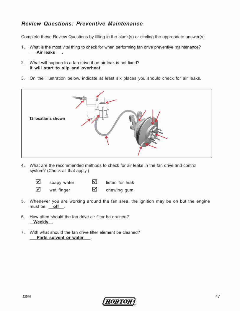
3. On the illustration below, indicate at least six places you shouldcheck for air leaks.
4. What are the recommended methods to check for air leaks in the fandrive and control system? (Check all that apply.)
soapy water listen for leak
wet finger chewing gum
5. Whenever you are working around the fan area, the ignition may beon but the engine must be
____________________________________________.
6. How often should the fan drive air filter be drained? ____________
7. With what should the fan drive filter element be cleaned?
__________________________________________________________

26 22540
8. When checking fan drive operation and inspecting for air leaks,what condition should each of the following items be in?
9. For each of the following fan drive systems, indicate how tomanually test fan drive engagement and disengagement. Place anX at points where a wire should be disconnected or draw a jumperwire at points where a component should be shorted out.
10. How often is fan drive preventive maintenance recommended?________________________________________________________________________________________________________________________________
ITEM CONDITION
Truck ignitionTruck engine
Truck air reservoirManual Override Switch
O nRunning
Fully depletedO n
Of fNot Running
At least 90 psi [6.21 bar]Auto
After completing Review Questions, check answers in Appendix D, Page 43.
Air Supply
N O
NC
+12 Volts A/C PressureSwitch (NO)
SolenoidValve
ThermalSwitch (NO)
OUT
Air Supply
N O
NC
+12 Volts
A/C PressureSwitch (NC)
SolenoidValve
ThermalSwitch (NC)
OUT

2722540
ITEM DESCRIPTION QTY
3 Mounting Bracket 1 42 Sheave Bearing 26 Sheave 1
72 Friction Facing 18 Journal Spacer 1
92 Socket Head Cap Screw * 152 Piston Assembly 1
(Includes 18, 19, & 46) 161,2 O-ring (Large) 1
18 Bearing Spacer 119 Hub Bearing (Split Ring) 1
222 Lock Nut 1 231,2 Cartridge Assembly 1
ITEM DESCRIPTION QTY
241,2 Face Seal Assembly 1(Replace Item 27 if Seal is round)
261,2 O-ring (Small) 127 Air Chamber Assembly 1
291,2 Socket Head Cap Screw 830 Stud Bolt 631 Lock Washer 632 Hex. Nut 6
443 Bearing Spacers 1(Inner & Outer)
461,2 System Sentry 147 Umbrella Check Valve 1
1 Denotes Repair Kit item.2 Denotes Super Kit item.3 Not used on all fan Drives.
34
444
6
7 98
18 1519 15
4616
2223
2426
27
29 31 32
30
S and HT/S AdvantageSplit Ring Bearing
47
* QTY. 8 for HT/S Type.* QTY 6 for S Type.
LESSON 5: Horton Fan Drive Components Objectives• identify the major
components of aHorton fan drive
• discuss basic fan driveoperation
Shown below and on the next page are the major components of aHorton HT/S fan drive.

28 22540
ITEM DESCRIPTION QTY
231,2 Cartridge Assembly 1241,2 Face Seal Assembly 1
(Replace Item 27 if Seal is round)252,3 Seal 1
(Advantage Drive only)261,2 O-ring (Small) 1
27 Air Chamber Assembly 1291,2 Socket Head Cap Screw 830 Stud Bolt 631 Lock Washer 632 Hex Nut 6
443 Bearing Spacers 1(Inner & Outer)
461,2 System Sentry 147 Umbrella Check Valve 1
34
444
6
7 98
1018
15 1915
46
1622
2324
2627
29 31 32
30
S and HT/SStandard and Advantage
47
1425
ITEM DESCRIPTION QTY
3 Mounting Bracket 1 42 Sheave Bearing 26 Sheave 1
72 Friction Facing 18 Journal Spacer 1
92 Socket Head Cap Screw *10 Hub Bearing 1
142 Spacer 1(Advantage Drive only)
152 Piston Assembly 1(Includes 18, 19, & 46)
161,2 O-ring (Large) 1 18 Bearing Spacer 1 19 Hub Bearing 1
222 Lock Nut 11 Denotes Repair Kit item.2 Denotes Super Kit item.3 Not used on all fan Drives.
* QTY. 8 for HT/S Type.* QTY 6 for S Type.

2922540
The journal spacer slips ontothe mounting bracket shaftbetween the sheave bearingsand the splined hub. Oneside of the spacer has a lip.The journal spacer must beinstalled with the lip sidepointing toward the splinedhub as shown.
Also, due to different sizedspacers with different mod-els of fan drives, retain the jour-nal spacer if it is removed dur-ing maintenance for reuse withthe same fan drive during re-
assembly. Failure to reuse the journal spacer with the same assembly mayresult in fan drive lock-up.
The splined hub has precision bearing at its center and slips onto theshaft, It is held in place by a large lock nut that screws onto the end ofthe shaft. The hub is free to spin independently of the sheave. Noticethe spring located around the hub. This spring disengages the drive by hold-ing the piston friction disc (PFD) away from the sheave.
The PFD has splines on its inside circumference that mate with the splineson the hub. The PFD simply slips onto the hub; it is not bolted in place.
The air chamber slips over the PFD, but bolts to the splined hub. ThePFD, splined hub, and air chamber rotate as one unit when the drive is en-gaged. Since the air chamber is bolted to the hub and not to the PFD, thePFD can move along the splines of the hub to engage and disengage thedrive.
To engage the fan drive, 90-120 psi (6.21-8.27 bar] of air pressure goes throughthe center of the shaft, through the air cartridge, and into the air chamber.This pressure pushes the PFD against the friction material. To disengage thedrive, the air pressure is removed and the spring on the hub pushes the PFDaway from the friction material.
Lip
When installing thejournal spacer, the sidewith the lip must pointtoward the splined hub.
The mounting bracket and shaft assembly (also called the journal) boltsto the front of the engine.
The sheave is essentially a pulley with a large disc on one end. A ring offriction material is bolted to the disc and bearings are pressed into thecenter of the sheave. The sheave and its bearings slip onto the mountingbracket shaft. Drive belts connect the sheave to the engine’s crankshaftpulley and whenever the engine is running the sheave is turning. Somesheaves are designed for only two belts, while other sheaves can accom-modate as many as five belts.
There are more than ahundred differentmounting bracketsavailable for differentmodels of trucks andengines.
Different sheaves areavailable for differenttrucks and engines.
Splined HubJournalSpacer

30 22540
Corrective Maintenance of a Horton heavy duty fan drive will be necessary ifthe fan drive develops an air leak, the friction material is worn, or the bearingsare rough. Several parts replacement kits are available from Horton-the SealKit, the Super Kit, and a Major Kit.
• If the fan drive has an air leak, install a Seal Kit.
• If the friction material is worn or the bearings are rough andthe fan drive is not equipped with a System Sentry, installthe appropriate Advantage Super Kit.
• If the friction material is wom or the bearings are rough andthe fan drive has a System Sentry, an Advantage Major Kitmay be used.
Before installing any kit, remove the fan drive from the truck.
Removing Fan Drive
The procedure for removing the fan drive varies from truck to truck-refer to thetruck’s service manual for a detailed description of thisprocess. In general, proceed as follows:
1 . Ensure the truck engine is off.
2. Remove the fan blade from the fan drive.
3 . Bleed the air from the truck’s reservoir and disconnect the airhose from the fan drive.
4 . Loosen or remove the drive belts.
5. The fan drive is rather heavy, ranging from 35-55 Lbs. [15.88-24.95 Kg]. Some mechanics like to use a hoist (i.e., cherrypicker) to support the drive while they unbolt it. If you use ahoist, be careful not to get the chain hoist tangled with the belts.
6. Remove the fan drive mounting bolts and lift the fan drive out ofthe engine compartment.
Objectives• remove and reinstall a
fan drive
• rebuild a fan driveusing the appropriate kit
LESSON 6: Corrective Maintenance
Further information is provided with instructions available with the repair kit.

3122540
Seal KitInstall a Seal Kit if an air leak has developed inside the fan drive or if theSystem Sentry has melted. The Seal Kit consists of the parts as listed anddescribed below.
O-rings These O-rings form an air seal between the air chamberand the Piston Friction Disc (PFD). One O-ring goes onthe air chamber, the other goes on the PFD.
Air The air cartridge fits inside the fan Drive journal shaft.Cartridge Air pressure comes up the center of the shaft, through
the cartridge, and into the air chamber. The cartridge hasa spring-loaded carbon tip that presses against the faceseal and forms a tight air seal while the drive is spinning.
If you have an older style cartridge with a U-cup seal,remove and discard the U-cup seal.
Face Seal The face seal screws into the center of the air chamberand forms an air seal with the carbon tip of the aircartridge.
Retaining The retaining ring holds the air cartridge inside the shaft.Ring When installing the retaining ring, the beveled side
must point down.
Cap Screws The torx button-head cap screws attach the air chamberto the hub. Tighten screws in a cross sequence to180 In. Lbs. [20.34 N-m].
System The System Sentry has left-handed threads and screwsSentry® into a boss on the PFD.
O-ring Apply lubricant to new O-rings before their installation.Lubricant
Anti-Seize Apply as lubricant to hub splines and PFD splines.
Umbrella A one-way valve that prevents moisture andValve contamination from entering inner drive assembly.
Be careful not to twist O-rings as they areinstalled.
Apply O-ring lubricant tothe outside of the aircartridge O-rings.
Replacement KitsHorton provides several parts replacement kits for rebuilding various fan drives.The appropriate manual is included in the kit.
IMPORTANT: Use all the parts in the kit.
Apply lubricant alongsplines of the hubassembly and the PFD.
Wear safety glasses anduse snap-ring pliers toremove and installretaining rings.
Remove the face seal witha 5/8” [1.59 cm] socket.

32 22540
Advantage™ Major Kits
Install an Advantage™ Major Kit if the friction material is worn or if thebearings are running rough. This kit can be used to repair any Advan-tage™ fan drive or upgrade an existing fan drive already equipped with a Sys-tem Sentry. The Advantage™ Major Kit includes the contents of the Seal Kitplus the parts as listed and described below.
Friction The friction material mounts to the sheave.Facing
Mounting Hardware to bolt the friction material to the sheave.Screws
Sheave Use a bearing press to remove the old bearings andBearings press the new bearings into the center of the sheave.
The bearings are prelubricated and sealed. Reuseexisting two-piece spacer.
DO NOT break the seals or attempt to regrease oldbearings.
Hub The splined hub assembly has bearings installed at theAssembly factory. Hub bearings no longer need to be replaced in
the field.
Lock Nut The 1-1/2" [3.81 cm] self-locking nut holds the hub ontothe shaft. Tighten nut to 150 Ft. Lbs. [203 N•m].
Split RingSpacer
3322540
Reinstalling the Fan Drive
After the kit has been installed and the fan drive reassembled, apply 90 psi[6.21 bar] air pressure and check the fan drive for air leaks. If no leaks exist,reinstall the fan drive onto the truck as follows:
1. Clean the fan drive mounting surface on the engine.
2. Using a portable hoist to hold the fan drive, bolt the fan drive tothe engine. Use flat washers on each manufacturer’s approved boltor studs - DO NOT use lock washers. Tighten the mounting boltsto the truck manufacturer’s specifications.
3 . Start the truck to recharge the air system. Using an air gauge, checkthat the air pressure to the fan drive is between 90-120 psi [6.21-8.27 bar]. Shut the truck off. Reconnect the air hose to the fan drive.
4 . Replace and tighten the belts to manufacturer’s specification.
5 . Check the fan blade for cracks or missing weights; then, remountthe blade to the fan drive. Tighten the lock nuts to 18 Ft.-Lbs.[24•Nm].
6 . Start the truck and let the air pressure build to at least 90 psi [6.21bar]. Shut off the truck.
7. Manually engage and disengage the fan drive by opening andclosing the electrical circuit going to the solenoid valve. For anormally-open electrical system, use a jumper across a sensor. For anormally-closed electrical system, open the circuit by disconnecting asensor wire. With the fan drive engaged, recheck the entire systemfor air leaks, or flip the manual override switch if so equipped.

34 22540
A. Air leak detected at air chamber pilot holeB. System Sentry® is blownC. Rough bearings when fan blade is spinning
(without System Sentry)D. Rough bearings when sheave is spinning
(with System Sentry)E. Air leak detected between air chamber and PFDF. Friction material worn to less than 1/16"
[1.59 mm] (with System Sentry)G. Air leak detected at System SentryH. Rough bearings and/or friction material worn
to less than 1/16" [1.59 mm] (with System Sentry)
Review Questions: Corrective Maintenance
Complete these Review Questions by filling in the blank(s) or circling the ap-propriate answer(s).
1. For each of the fan drive situations below that require correctivemaintenance, indicate if you would install a Seal, Super, or Major Kit.
2 . What should be done with the U-cup when installing a Seal Kit intoan HT/S fan drive with an old style cartridge?
A. Remove it and throw it away.
B. Replace it with the new style U-cup from the kit.
C. Leave it inside the shaft beneath the new air cartridge.
3 . After removing the cap screws, do the following to help remove theair chamber from the PFD:_____________________________________.
4 . When removing or installing the air cartridge retaining ring,follow proper safety procedures and ___________________________.
5 . It is important to install the journal spacer with _________________.
6 . When installing a new O-ring, be careful not to ________________.
7 . What is special about the threads on the System Sentry fuse?_______________________________________________________________.
PROBLEM KITSeal Super Major
After completing Review Questions, check answers in Appendix C, Page 43.
3522540
Please Print Legibly
Name: Date:Date:Company:Address: Phone:
Fax:
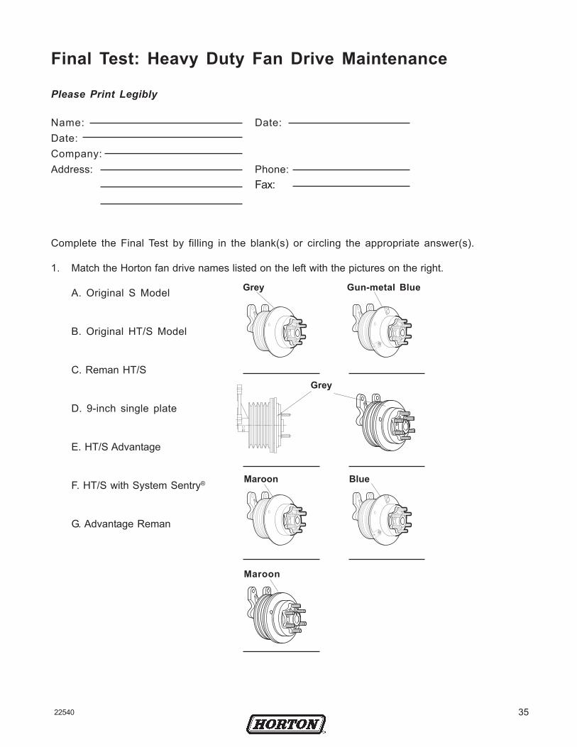
Complete the Final Test by filling in the blank(s) or circling the appropriate answer(s).
1. Match the Horton fan drive names listed on the left with the pictures on the right.
A. Original S Model
B. Original HT/S Model
C. Reman HT/S
D. 9-inch single plate
E. HT/S Advantage
F. HT/S with System Sentry®
G. Advantage Reman
Grey Gun-metal Blue
Grey
Maroon Blue
Maroon
Final Test: Heavy Duty Fan Drive Maintenance

36 22540
A. Mounting BracketB. Sheave BearingC. SheaveD. Friction FacingE. Journal SpacerF. PistonG. O-ring (Large)H. Bearing SpacerI. Hub Bearing
(Split Ring)J. Cartridge Assy.K. Face Seal Assy.L. O-ring (Small)M. Air Chamber
AssemblyN. Bearing SpacersO. System Sentry®
P. UmbrellaCheck Valve
2. Match the components listed on the left with each of the components pictured in both figures.
A. Mounting BracketB. Sheave BearingC. SheaveD. Friction FacingE. Journal SpacerF. Hub BearingG. Spacer (Advatage
Drive only)H. PistonI. O-ring (Large)J. Bearing SpacerK. Hub BearingL. Cartridge Assy.M. Face Seal Assy.N. Seal (Advantage
Drive only)O. O-ring (Small)P. Air Chamber
AssemblyQ. Bearing SpacersR. System Sentry®
S. UmbrellaCheck Valve

3722540
5 . If a truck has a normally-open electrical system, the air supply should be connectedto the normally-_____________ inlet port of the 3-way solenoid valve.
6. In a normally-open electrical system, the fan drive will engage if any switchopens /closes.
7 . On the electrical diagram below, connect the electrical components for a normally-closed electrical system and connect the air supply to the correct inlet port onthe solenoid valve.
Normally-Closed Electrical System
Normally-Open Electrical System
3. When installing a 3-way solenoid valve, always connect the air line that goes tothe fan drive to the valve’s ________ port.
4 . On the diagram below, connect the electrical components for a normally-openelectrical system, and connect the air supply to the correct inlet port on thesolenoid valve.
Air Supply
N O
NC
+12 Volts
A/C PressureSwitch (NO)
SolenoidValve
ThermalSwitch (NO)
Manual OverrideSwitch (NO)
Air Supply
N O
NC
+12 Volts
A/C PressureSwitch (NC)
SolenoidValve
ThermalSwitch (NC)
Manual OverrideSwitch (NC)

38 22540
8 . If a truck has a normally-closed electrical system, the air supply should be connectedto the normally-_____________ inlet port of the 3-way solenoid valve.
9. In a normally-closed electrical system, the fan drive will engage if any switchopens /closes.
10. If a truck has an ECM based control system, it will have a (an):
A. A/C Pressure Switch.
B. Thermal Switch.
11. What is the most important thing to check for when performing fan drive PM?_______________________________________________________________________________
12. When working around the fan, the ignition may be on but the engine must be___________.
13. When installing a Seal kit into an HT/S fan drive with an old style cartridge,what should be done with the U-cup?
_______________________________________________________________________________
14. When installing the journal spacer, the side with the lip must be facing__________________________.
15. On the illustration below, indicate at least six places to check for air leaks.

3922540
17. For the fan drive system below, place an X at the point where a wire would bedisconnected to manually test fan drive engagement.
16. For the fan drive system below, indicate where a jumper wire would be placed tomanually test fan drive engagement.
Air Supply
N O
NC
+12 Volts A/C PressureSwitch (NO)
SolenoidValve
ThermalSwitch (NO)
Air Supply
N O
NC
+12 Volts A/C PressureSwitch (NO)
SolenoidValve
ThermalSwitch (NO)
OUT
OUT

40 22540
18. How often should PM be performed on a fan drive?
19. Below is a list of fan drive situations requiring corrective maintenance. Foreach situation, indicate whether to install a Seal, Super, or Major Kit.
A. Air leak detected at air chamber pilot holeB. System Sentry® is blownC. Rough bearings when fan blade is spinning (without
System Sentry)D. Rough bearings when sheave is spinning (with System
Sentry)E. Air leak detected between air chamber and PFDF. Friction material worn to less than 1/16" [1.59 mm]
(with System Sentry)G. Air leak detected at System SentryH. Rough bearings and/or friction material worn to less
than 1/16" [1.59 mm] (with System Sentry)
PROBLEM KITSeal Super Major
4122540
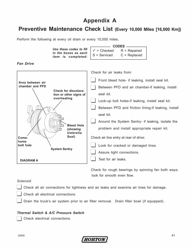
Fan Drive
Check for air leaks from:
Front bleed hole- if leaking, install seal kit.
Between PFD and air chamber-if leaking, install
seal kit.
Lock-up bolt holes-if leaking, install seal kit.
Between PFD and friction lining-if leaking, install
seal kit.
Around the System Sentry- if leaking, isolate the
problem and install appropriate repair kit.
Check air line entry at rear of drive:
Look for cracked or damaged lines.
Assure tight connections.
Test for air leaks.
Check for rough bearings by spinning fan both ways; look for smooth even flow.
Solenoid
Check all air connections for tightness and air leaks and examine air lines for damage.
Check all electrical connections.
Drain the truck’s air system prior to air filter removal. Drain filter bowl (if equipped).
Thermal Switch & A/C Pressure SwitchCheck electrical connections.
DIAGRAM A
CODES = Checked R = Repaired
S = Serviced C = Replaced
Perform the following at every oil drain or every 10,000 miles.
Use these codes to fillin the boxes as eachitem is completed:
Area between airchamber and PFD
Check for discolora-tion or other signs ofoverheating
Come-homebolt hole
Bleed Hole(showingUmbrellaSeal)
System Sentry
Appendix APreventive Maintenance Check List (Every 10,000 Miles [16,000 Km])

42 22540
FAN
Check for bent , cracked, or miss-ing blades, loose rivets, and looseor missing weights. Replace fan ifdefective.
Tighten fan blade nuts to at least18 Ft. Lbs. [24 N•m] torque.
Check for adequate clearancebetween fan and fan shroud.
FAN BELTS
Check belt condition. Replace beltsif worn or frayed.
Check for proper belt tension.Tighten to manufacturer specifica-tions as needed.Check for properbelt al ignment.
DRIVE AND CONTROLS
Inspect all electrical connections andwires. Tighten if loose; replace ifdamaged. Verify drive engagementand disengagement.
Use the codes as shown above to fill inthe boxes as each item is completed:
Appendix BPreventive Maintenance Check List (Every 25,000 Miles [40,000 Km])
DIAGRAM C
Normally-Open(Parallel) Electrical
System
DIAGRAM B
Normally-Closed(Series) Electrical
System• With engine temperature
below the thermal switchsetting, start engine andbuild up air pressure
• Remove either wire fromthe thermal switch toengage the fan drive, OR
• Flip the Manual overrideswitch to engage drive.
• Reconnect the wire toterminal of thermalswitch to exhaust air anddisengage the fan drive.
• With engine temperaturebelow the thermal switchsetting, start engine andbuild up air pressure.
• Install jumper wirebetween terminals ofthermal switch to engagefan drive, OR
• Flip the Manual overrideswitch to engage drive.
• Remove jumper wire toexhaust air and disen-gage fan drive.
CODES = Checked R = Repaired
S = Serviced C = Replaced

4322540
Check all air connections forair leaks.
Drain air filter. Clean the bowland filter (if equipped).
Check friction facing for wear.Replace when worn to 1/16 [1.59 mm]thick.
DIAGRAM D
Check for air leaks infan drive.
• Normally Open Electrical System
1. To determine if air isleaking from drive, turnengine off to engagedrive.
2 . Lightly brush a bubblesolution on bleed holeon fan pilot, betweenair chamber and PFD,around Come-Home Holeson PFD, and SystemSentry® (see Diagram D).
• Normally Closed Electrical System
1. To determine if air isleaking from drive, turnkey to on position (DONOT START ENGINE).Ins ta l l jumper w i rebetween thermal switchterminals to engagedrive.
2 . Lightly brush a bubblesolution on bleed holeon fan pilot, betweenair chamber and PFD,around Come-Home
Holes on PFD, and Sys tem Sentry (see Diagram D).
3 . Remove jumper wireonce leak is found.
Check bearings in fandrive for smooth andeven rotation. Enginemust be off and fandisengaged.
• Normally Closed Electrical System
1. Turn key to on positionto disengage Drive (DONOT START ENGINE).
2 . Rotate fan to check forfront bearing roughness.
3 . If belts are removed,rotate sheave to check forfor pulley bearing rough-ness.
If bearing roughness isdetected, install the
appropriate kit.
Area between airchamber and PFD Check for discol-
oration or othersigns of over-heating
Come-homebolt hole
Bleed Hole(showingUmbrellaSeal)System Sentry

44 22540
Appendix CReview Question Answers
Review Questions: Fan Drive Control Systems
Complete these Review Questions by filling in the blank(s) or circling theappropriate answer(s).
1 . When installing a 3-way solenoid valve, connect the air line goingto the fan drive to the valve’s outlet port.
2. When a fan drive is disengaged, where does air pressure in thefan drive’s air chamber go?It exhausts out the open port of the solenoid valve.
3. On the diagram below, connect the electrical components fora normally-open electrical system and indicate if the air supplyis connected to the solenoid valve’s normally-open or normally-closed inlet port.
4. In a normally-open fan drive electrical system, the switches andsensors are wired in series / parallel .
Normally-Open Electrical System
Air Supply
N O
NC
+12 Volts
A/C PressureSwitch (NO)
SolenoidValve
ThermalSwitch (NO)
Manual OverrideSwitch (NO)

4522540
5 . If a truck has a normally-open electrical system, the air supplyshould be connected to the normally-closed inlet port of the 3-waysolenoid valve.
6 . In a normally-open electrical system, when all switches are open,the solenoid is energized / de-energize and the fan drive isengaged / disengaged .
7 . In a normally-open electrical system, if any switch closes, the solenoidwill energize /de-energize and the fan drive will engage / disengage.
8 . On the diagram below, connect the electrical components fora normally-closed electrical system and indicate if the airsupply is connected to the solenoid valve’s normally-open ornormally-closed inlet port.
Normally-Closed Electrical System
9. In a normally-closed fan drive electrical system, the switches andsensors are wired in series / parallel.
10. If a truck has a normally-closed electrical system, the air supply shouldbe connected to the normally-open inlet port of the 3-way solenoidvalve.
11. In a normally-closed electrical system, when all switches are closed,the solenoid is energized / de-energized and the fan drive isengaged /disengaged .
Air Supply
N O
NC
+12 Volts
A/C PressureSwitch (NC)
SolenoidValve
ThermalSwitch (NC)
Manual OverrideSwitch (NC)

46 22540
12. In a normally-closed electrical system, if any switch opens, thesolenoid will energize / de-energize and the fan drive willengage / disengage.
13 . ECMs are being added to new truck designs to improve engine performance , reliability , and fuel efficiency .
14. An ECM is essentially a digital computer, consisting of a microprocessor , (RAM) Ready Access Memory ,and (ROM) Read Only Memory .
4722540
Review Questions: Preventive Maintenance
Complete these Review Questions by filling in the blank(s) or circling the appropriate answer(s).
1. What is the most vital thing to check for when performing fan drive preventive maintenance? Air leaks .
2. What will happen to a fan drive if an air leak is not fixed?It will start to slip and overheat.
3 . On the illustration below, indicate at least six places you should check for air leaks.
12 locations shown
4. What are the recommended methods to check for air leaks in the fan drive and controlsystem? (Check all that apply.)
soapy water listen for leak
wet finger chewing gum
5. Whenever you are working around the fan area, the ignition may be on but the enginemust be off .
6. How often should the fan drive air filter be drained? Weekly .
7. With what should the fan drive filter element be cleaned? Parts solvent or water .

48 22540
O nRunning
Fully depletedO n
8. When checking fan drive operation and inspecting for air leaks, what condition shouldeach of the following items be in?
ITEM CONDITION
Truck ignitionTruck engine
Truck air reservoirManual Override Switch
Of fNot Running
At least 90 psiAuto
9. For each of the following fan drive systems, indicate how to manually test fan driveengagement and disengagement. Place an X at points where a wire should be discon-nected or draw a jumper wire at points where a component should be shorted out.
10. How often should fan drive preventive maintenance be performed? 10,000 mile [16,000 Km] walk around . 25,000 mile [40.000 Km] full PM .
N ONC
N O
NC
N O
NC

4922540
KITSeal Super Major
Review Questions: Corrective Maintenance
Complete these Review Questions by filling in the blank(s) or circling the appropriate answer(s).
1. For each of the fan drive situations below that require corrective maintenance, indicate if youwould install a Seal, Super, or Major Kit.
A. Air leak detected at air chamber pilot holeB. System Sentry® is releasedC. Rough bearings when fan blade is spinning
(without System Sentry)D. Rough bearings when sheave is spinning
(with System Sentry)E. Air leak detected between air chamber and PFDF. Friction material worn to less than 1/16"
[1.59 mm] (with System Sentry)G. Air leak detected at System SentryH. Rough bearings and/or friction material
worn to less than 1/16" [1.59 mm] (with SystemSentry)
PROBLEM
2. What should be done with the U-cup when installing a Seal Kit into an HT/S fan drivewith an old style cartridge?
A. Remove it and throw it away.B. Replace it with the new style U-cup from the kit.C. Leave it inside the shaft beneath the new air cartridge.
3 . After removing the cap screws, do the following to help remove the air chamberfrom the PFD:Apply air pressure to fan drive .
4. When removing or installing the air cartridge retaining ring, follow proper safety proce-dures and wear safety glasses .
5. It is important to install the journal spacer with lip facing up .
6 . When installing a new O-ring, be careful not to twist the o-ring .
7 . What is special about the threads on the System Sentry fuse? They are left-handed threads .

50 22540
Notes

5122540

Horton, Inc.2565 Walnut St.Roseville, MN 55113, USAPhone: +1 (651) 361-6400Toll-free: +1 (800)-621-1320Fax: +1 (651) 361-6801Web site: www.hortonww.come-mail: [email protected]
© 2004 Horton, Inc. All rights reserved. Printed in USA.QS-9000 certified.22540-F-0504
Horton, Inc. is a Horton Holding, Inc. company.Horton Holding, Inc., Roseville, MN USA


