43
Heavy-Duty Steel Bar Grating

Heavy-Duty Steel Bar Grating

Laurel Steel Division
Company Profile
Laurel Steel Products, a Division of MARWAS
Steel, Scottdale, PA, has been manufacturing
heavy-duty steel bar grating since 1983, and
is a member in good standing of the Metal
Bar Grating Division of the National
Association of Architectural Metal
Manufacturers. Over the past 18 years,
Laurel Steel has grown into a major
producer in the heavy-duty grating market,
with a reputation for quality products,
on-time deliveries and competitive prices.
Located in rural Everson, PA, but convenient
to interstates for ready access to major
transportation routes, Laurel Steel is well
positioned to expand its current 30,000
square foot manufacturing facility as growth
in all market segments continues.
Laurel Steel has continually modernized
its equipment and significantly increased
fabrication capacity. Large capacity
hydraulic presses with automated feed
lines, an extensive and ever-widening range
of standard fixtures and high-production
robotics are all utilized to supply all of
your heavy-duty grating needs efficiently
and economically.
In addition to its core heavy-duty grating
product line, Laurel Steel has become
one of the largest suppliers of roadway/
commercial inlet frames and grates to the
local construction industry. And throughout
its history, Laurel Steel has never been
afraid to tackle the out-of-the-ordinary
‘specials’ that other manufacturers avoid.
Hopper covers, heavy material-handling
screens, high impact-resistant grates from
special alloys — even complex radio
frequency screens for national security
installations — have been and continue to
be successfully manufactured at Laurel Steel.
Recently, Laurel Steel has satisfied the
needs of contractors who are required to
provide gratings heavy enough to withstand
vehicle loads, yet still comply with the federal
Americans with Disabilities Act (ADA).
2222
Laurel Steel also services its growing
customer base with a large inventory of stan-
dard walkway grating and expanded metal
products, available in either stock panels or
completely fabricated projects.
Heavy-Duty Grating... Inlets... Special Fabrications... Walkway Grating...Expanded Metal...
Call Laurel Steel for any of these items,
and let us put our experience and efficiency
to work for you.
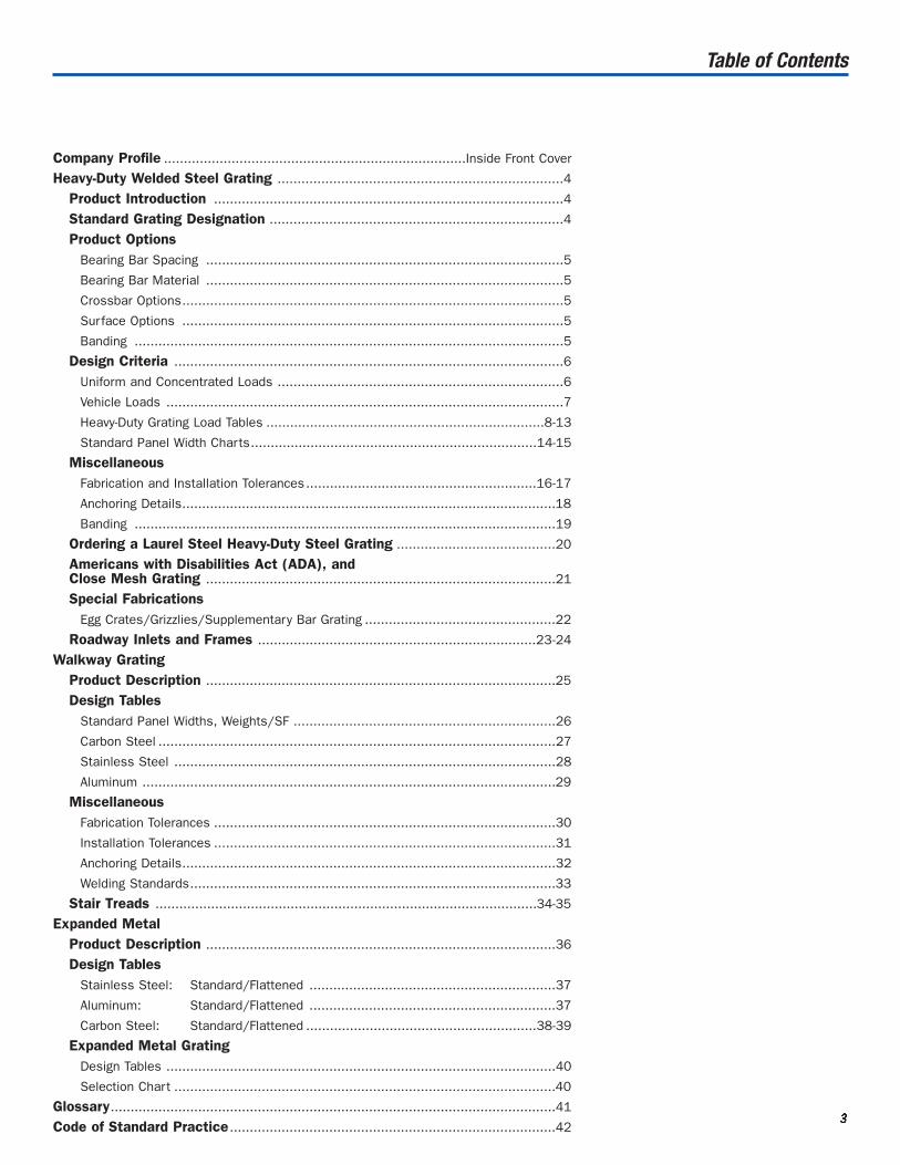
Table of Contents
Company Profile ............................................................................Inside Front Cover
Heavy-Duty Welded Steel Grating ........................................................................4
Product Introduction ........................................................................................4
Standard Grating Designation ..........................................................................4
Product OptionsBearing Bar Spacing ..........................................................................................5
Bearing Bar Material ..........................................................................................5
Crossbar Options................................................................................................5
Surface Options ................................................................................................5
Banding ............................................................................................................5
Design Criteria ..................................................................................................6
Uniform and Concentrated Loads ........................................................................6
Vehicle Loads ....................................................................................................7
Heavy-Duty Grating Load Tables ......................................................................8-13
Standard Panel Width Charts........................................................................14-15
MiscellaneousFabrication and Installation Tolerances..........................................................16-17
Anchoring Details..............................................................................................18
Banding ..........................................................................................................19
Ordering a Laurel Steel Heavy-Duty Steel Grating ........................................20
Americans with Disabilities Act (ADA), and Close Mesh Grating ........................................................................................21
Special FabricationsEgg Crates/Grizzlies/Supplementary Bar Grating ................................................22
Roadway Inlets and Frames ......................................................................23-24
Walkway GratingProduct Description ........................................................................................25
Design TablesStandard Panel Widths, Weights/SF ..................................................................26
Carbon Steel ....................................................................................................27
Stainless Steel ................................................................................................28
Aluminum ........................................................................................................29
MiscellaneousFabrication Tolerances ......................................................................................30
Installation Tolerances ......................................................................................31
Anchoring Details..............................................................................................32
Welding Standards............................................................................................33
Stair Treads ................................................................................................34-35
Expanded MetalProduct Description ........................................................................................36
Design TablesStainless Steel: Standard/Flattened ..............................................................37
Aluminum: Standard/Flattened ..............................................................37
Carbon Steel: Standard/Flattened ..........................................................38-39
Expanded Metal GratingDesign Tables ..................................................................................................40
Selection Chart ................................................................................................40
Glossary................................................................................................................41
Code of Standard Practice ..................................................................................423333
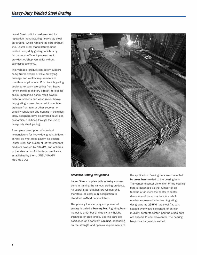
Heavy-Duty Welded Steel Grating
4444
Laurel Steel built its business and its
reputation manufacturing heavy-duty steel
bar grating, which remains its core product
line. Laurel Steel manufactures hand-
welded heavy-duty grating, which is by
far the most efficient process, as it
provides job-shop versatility without
sacrificing economy.
This versatile product can safely support
heavy traffic vehicles, while satisfying
drainage and air flow requirements in
countless applications. From trench grating
designed to carry everything from heavy
forklift traffic to military aircraft, to loading
docks, mezzanine floors, vault covers,
material screens and wash racks, heavy-
duty grating is used to permit immediate
drainage from rain or other sources, or
simplify ventilation and heating in buildings.
Many designers have discovered countless
economical solutions through the use of
heavy-duty steel grating.
A complete description of standard
nomenclature for heavy-duty grating follows,
as well as what rules govern its design.
Laurel Steel can supply all of the standard
products covered by NAAMM, and adheres
to the standards of voluntary compliance
established by them. (ANSI/NAAMM
MBG 532-00)
Standard Grating Designation
Laurel Steel complies with industry conven-
tions in naming the various grating products.
All Laurel Steel gratings are welded and,
therefore, all carry a W designation in
standard NAAMM nomenclature.
The primary load-carrying component of
grating is called a bearing bar. A grating bear-
ing bar is a flat bar of virtually any height,
thickness or steel grade. Bearing bars are
positioned at a constant spacing, depending
on the strength and open-air requirements of
the application. Bearing bars are connected
by cross bars welded to the bearing bars.
The center-to-center dimension of the bearing
bars is described as the number of six-
teenths of an inch; the center-to-center
dimension of the cross bars is a whole
number expressed in inches. A grating
designated as 22-W-4 has steel flat bars
spaced twenty-two sixteenths of an inch
(1-3/8") center-to-center, and the cross bars
are spaced 4" center-to-center. The bearing
bar/cross bar joint is welded.

Product Options
5555
This section describes the options available
to a designer or user of heavy-duty steel
grating. The accompanying sketch illustrates
those options.
Bearing Bar Spacings
Theoretically, any bearing bar spacing
can be provided; however, the array of
“standard” industry spacings are adequate
to cover the overwhelming majority of
heavy-duty grating applications.
Pages 8 through 13 contain design tables for
those spacings that are most common for
heavy-duty steel bar grating. In addition to
those designs, Laurel Steel has assembly
fixtures for many other spacings which are
less commonly specified. Those spacings are
shown below:
7W 8W 9W 12W 13W 16W
Having all of these spacing options means
that Laurel Steel can satisfy practically any
clear opening requirement. By varying the
bearing bar size to accommodate a particular
strength criteria, design choices are nearly
limitless. Grating designs with openings
from 3/16" to 2" and beyond, capable of
supporting the heaviest loads, are possible.
Bearing Bar Material
While the bearing bar material of most
Laurel Steel heavy-duty grating is supplied in
conventional carbon steel grades — such as
ASTM A709, Grade 36 — grating can be
fabricated in just about any material, as
long as it can be practically obtained from
a mill, warehouse or processor. High
strength carbon steel and weathering steel
grades, as well as common grades of
stainless steel, can be used to fabricate
heavy-duty welded steel bar grating. Laurel
Steel is a major supplier of grating fabricated
from abrasion-resistant steels for that
demanding application. Please inquire about
the availability of special grades.
Cross Bar Options
The cross bar of a heavy-duty grating rigidly
holds the bearing bars at the specified
spacing. The standard cross bar used in
Laurel Steel heavy-duty grating is a smooth
round cross bar, the size of which complies
with NAAMM cross sectional area require-
ments. On some applications, where traffic
is primarily in the direction of the grating
cross bars, or where wheels turn directly
on the grating, a rectangular cross bar
provides additional lateral stiffness and load
distribution, ensuring serviceability. Bottom
cross bars, round or rectangular, are also
available for additional load distribution.
Round cross bars are plug welded to bearing
bars. Rectangular cross bars are welded
to bearing bars using various methods
depending on material, bearing bar spacing,
and other factors.
Surface Options
For most applications a smooth bearing bar
is adequate. Where additional traction or skid
resistance is required, a serrated surface
can be applied to grating bearing bars. For
maximum skid resistance, grating can be
supplied with serrated bearing bars and
rectangular, serrated cross bars.
Banding
A flat bar can be welded to the ends of the
grating panel for cosmetic reasons, or to
provide additional distribution of grating bars
to supports. Unless otherwise directed, the
band bar is of the same depth and thickness
as the bearing bar. The standard weld
pattern for banding is described by NAAMM
and is shown on page 19.
WIDTH
BEARING BAR SPACING
CL
CL
CROSS BAR SPACING
CL
CL
SPAN
SERRATED RECTANGULAR CROSS BAR
SERRATED BEARING BAR
SMOOTH BEARING BAR
SPECIFY BEARING BAR HEIGHT & THICKNESS
SPECIFY HEIGHT & THICKNESS OF RECTANGULAR CROSS BAR
SMOOTH RECTANGULAR CROSS BAR
SPECIFY Ø OF ROUND CROSS BAR
BAND BAR (OPTIONAL)

Design Criteria for Heavy-Duty Grating
6666
b = bearing bar thickness = 0.375"
d = bearing bar height = 3"
Allowable stress, F = 20,000 psi A-36 steel
Modulus of Elasticity, E = 29,000,000 psi A-36 steel
Span, L = 48"
Bearing bar spacing, AW = 2.375"
Number of bearing bars/ft width, K = 12/2.375 = 5.0526
Section Modulus/ft width, SgSg = Kbd2/6 = 5.0526 x 0.375 x (3)2 /6 = 2.842 in3
Moment of Inertia/ft width, IgIg = Kbd3/12 = 5.0526 x 0.375 x (3)3 /12 = 4.263 in4
Maximum bending moment/ft width, Mg = FSg
Mg = 20,000 x 2.842 = 56,840 lb-in
For the design of heavy-duty bar grating, load
bearing capabilities and deflections are
based on the structural properties of the
bearing bars and the number of bearing bars
supporting the load. Grating is designed so
that the allowable stresses of the metals
used are not exceeded when design loads
are applied, or if deflection governs, specified
allowances for deflection are not exceeded.
Grating Design Based on Concentrated and Uniform Loads
Static concentrated and uniform loads are
handled using simple moment formulas,
assuming simply supported beams,
with maximum moments and deflections
occurring at midspan. Complete load tables
which provide uniform and concentrated
loads for most common heavy-duty grating
spacings and bearing bar sizes are given in
the NAAMM Heavy-Duty Bar Grating Manual
MBG 532. Those tables can be viewed and
downloaded from the NAAMM website
www.naamm.org. The method by which those
values are calculated is illustrated in a
design example.
Uniform Load Concentrated Load
U = 98Mg/L2 = 96 x 56,840/(48)2 = 2368 lbs/sq. ft.
D = 5UL4/4608EIg = 5 x 2368 x (48)4/4608 x 29,000,000 x 4.263 = 0.110 inches
C = 4Mg/L = 4 x 56,840/48 = 4737 pounds/foot width
DC = CL3/48EIg = 4737 (48)3/48 x 29,000,000 x 4.263 = 0.088 inches
Calculate the concentrated midspan and uniform load bearing capabilities, and resultant
deflections, of a 38-W-4 (3 x 3/8) heavy-duty welded steel bar grating on a 48" span:
NOTE: For each load case, deflection is <0.12" (L/400), so design is satisfactory.

Vehicular Load Design
Design of heavy-duty steel bar grating for
vehicular loads is based on the American
Association of State Highway and
Transportation Officials (AASHTO) Standard
Specifications for Highway Bridges. Whereas
the Concentrated and Uniform Loads as dis-
cussed previously are based on one foot of
grating width, AASHTO rules allow for the dis-
tribution of loads over a specified area.
According to AASHTO Article 3.27.3.1
“A wheel load shall be distributed, normal
to the main elements, over a width equal
to 1-1/4" per ton of axle load plus twice the
distance center-to-center of main elements.
The portion of the load assigned to each
main element shall be applied uniformly
over a length equal to the rear tire width
(22.4 inches for H-25, 20 inches for H-20,
15" for H-15).”
How these formulas impact design is
illustrated in the accompanying chart.
For the chart, the following nomenclature
is used:
a = Partial Load Contact Area
Parallel to the Span (in inches)
b = Partial Load Contact Area
Normal to Span, = a + (2s),
where s = c/c of bearing bars
In addition to the H-25 (22.4"), H-20 (20")
and H-15 (15") classifications as discussed
in the AASHTO Article, a is further defined for
the following cases:
5-Ton Capacity Lift Truck, a = 11"
3-Ton Capacity Lift Truck, a = 7"
1-Ton Capacity Lift Truck, a = 4"
Example: In designing a 19W4 heavy-duty
steel bar grating (which has bearing bars
spaced at 1-3/16" center-to-center) to
support an H-20 load, the specified
20,800# wheel load is distributed
over 20" in the direction of the bearing
bar, and 22-3/8" normal to the bearing
bar (20" + 2s). Therefore, 18.8 bearing bars
(24-3/4" / 1-3/16") participate in
resisting the load.
The following chart illustrates how various loads are distributed on a 19W4 Steel Grating.
7777
The AASHTO load distribution formulas can
result in grating designs requiring larger
Section Moduli for lighter loads on shorter
spans. For example, the maximum safe clear
span for a Type 19W4 grating with a
1-1/2 x 1/4" bearing bar, when designing for
an AASHTO H-20 wheel load (20,800#) is
16". That same grating design has a smaller
safe span (13") when the design
criteria is just a 1 Ton capacity forklift
(3425# wheel load) because of the
difference in how loads are distributed.
Care should be taken to apply the most
severe potential loading to which the grating
may be subjected.
Note also that NAAMM publishes a
comprehensive ENGINEERING DESIGN
MANUAL (MBG 534) which is an excellent
resource for the design of heavy-duty steel
bar grating. As a service to our customers,
Laurel Steel has software programs devel-
oped for all loading conditions and can
provide design information specific to your
requirement. Please do not hesitate to
contact us, via phone, fax or e-mail.
The load tables shown on the following
pages provide common grating designs
and bar sizes, along with the maximum
recommended span for the six load
categories shown in the above chart.
The information contained herein has been preparedin accordance with generally accepted engineeringprinciples. However, Laurel Steel disclaims anyresponsibility for any errors that may be contained herein. The user of the information contained hereinshould check the information supplied, and make an independent determination as to its applicability toany particular project or application.
Design Load Wheel Load(includes 30% impact)
bano. Bearing Bars
under load (b/bearing bar
centers)
Load Distribution
H-25 26,000# 22.4" 25" + 2(1-3/16) 23.0or 27.375"
H-20 20,800# 20" 20" + 2(1-3/16") 18.8or 22.375"
H-15 15,600# 15" 15"+ 2(1-3/16") 14.6or 17.375"
5 - Ton 13,480# 11" 11"+ 2(1-3/16") 11.3or 13.375"
3 - Ton 8,730# 7" 7" + 2(1-3/16") 7.9or 9.375"
1 - Ton 3,425# 4" 4" + 2(1-3/16") 5.4or 6.375"
Design Loads Distributed on a 19W4 Steel Grating
Maximum Safe Clear Span
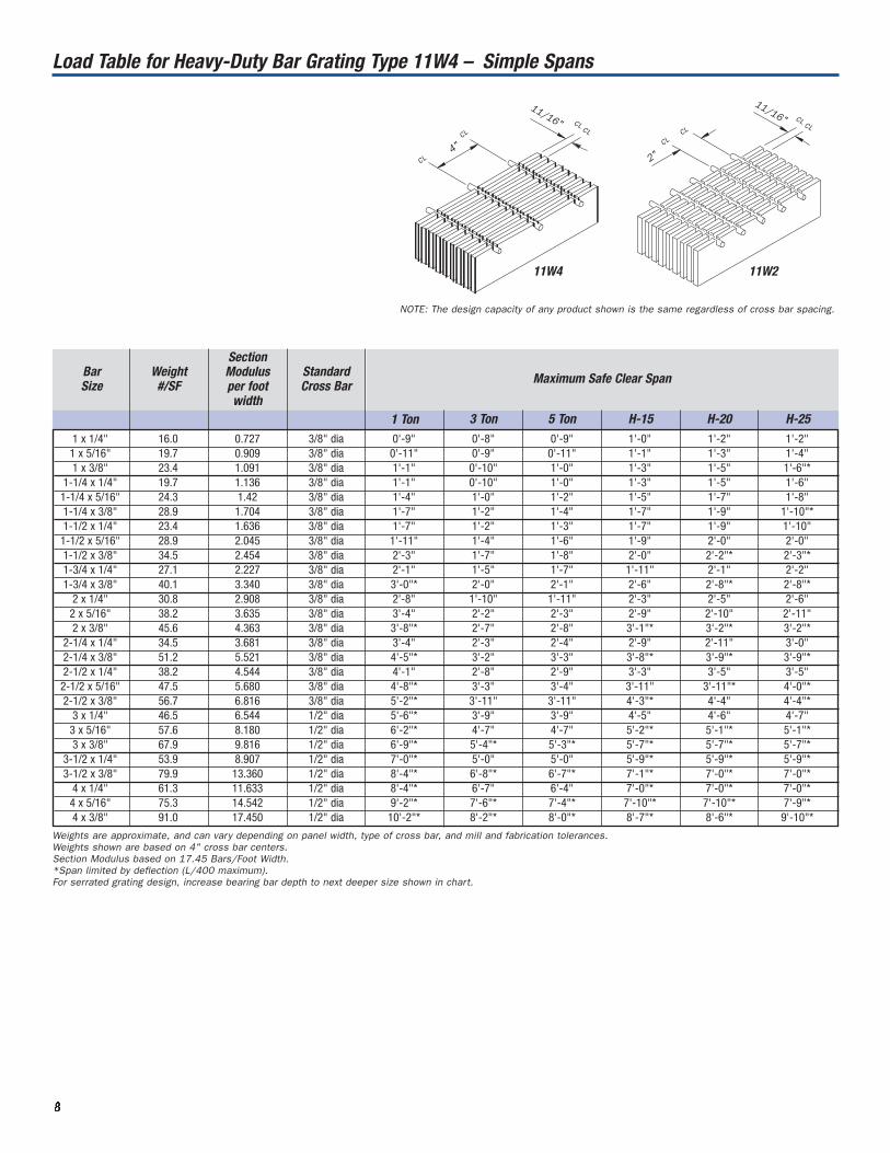
Load Table for Heavy-Duty Bar Grating Type 11W4 – Simple Spans
BarSize
Weight#/SF
SectionModulus per foot width
StandardCross Bar
1 Ton 3 Ton 5 Ton H-15 H-20 H-251 x 1/4" 16.0 0.727 3/8" dia 0'-9" 0'-8" 0'-9" 1'-0" 1'-2" 1'-2"1 x 5/16" 19.7 0.909 3/8" dia 0'-11" 0'-9" 0'-11" 1'-1" 1'-3" 1'-4"1 x 3/8" 23.4 1.091 3/8" dia 1'-1" 0'-10" 1'-0" 1'-3" 1'-5" 1'-6"*
1-1/4 x 1/4" 19.7 1.136 3/8" dia 1'-1" 0'-10" 1'-0" 1'-3" 1'-5" 1'-6"1-1/4 x 5/16" 24.3 1.42 3/8" dia 1'-4" 1'-0" 1'-2" 1'-5" 1'-7" 1'-8"1-1/4 x 3/8" 28.9 1.704 3/8" dia 1'-7" 1'-2" 1'-4" 1'-7" 1'-9" 1'-10"*1-1/2 x 1/4" 23.4 1.636 3/8" dia 1'-7" 1'-2" 1'-3" 1'-7" 1'-9" 1'-10"1-1/2 x 5/16" 28.9 2.045 3/8" dia 1'-11" 1'-4" 1'-6" 1'-9" 2'-0" 2'-0"1-1/2 x 3/8" 34.5 2.454 3/8" dia 2'-3" 1'-7" 1'-8" 2'-0" 2'-2"* 2'-3"*1-3/4 x 1/4" 27.1 2.227 3/8" dia 2'-1" 1'-5" 1'-7" 1'-11" 2'-1" 2'-2"1-3/4 x 3/8" 40.1 3.340 3/8" dia 3'-0"* 2'-0" 2'-1" 2'-6" 2'-8"* 2'-8"*
2 x 1/4" 30.8 2.908 3/8" dia 2'-8" 1'-10" 1'-11" 2'-3" 2'-5" 2'-6"2 x 5/16" 38.2 3.635 3/8" dia 3'-4" 2'-2" 2'-3" 2'-9" 2'-10" 2'-11"2 x 3/8" 45.6 4.363 3/8" dia 3'-8"* 2'-7" 2'-8" 3'-1"* 3'-2"* 3'-2"*
2-1/4 x 1/4" 34.5 3.681 3/8" dia 3'-4" 2'-3" 2'-4" 2'-9" 2'-11" 3'-0"2-1/4 x 3/8" 51.2 5.521 3/8" dia 4'-5"* 3'-2" 3'-3" 3'-8"* 3'-9"* 3'-9"*2-1/2 x 1/4" 38.2 4.544 3/8" dia 4'-1" 2'-8" 2'-9" 3'-3" 3'-5" 3'-5"2-1/2 x 5/16" 47.5 5.680 3/8" dia 4'-8"* 3'-3" 3'-4" 3'-11" 3'-11"* 4'-0"*2-1/2 x 3/8" 56.7 6.816 3/8" dia 5'-2"* 3'-11" 3'-11" 4'-3"* 4'-4" 4'-4"*
3 x 1/4" 46.5 6.544 1/2" dia 5'-6"* 3'-9" 3'-9" 4'-5" 4'-6" 4'-7"3 x 5/16" 57.6 8.180 1/2" dia 6'-2"* 4'-7" 4'-7" 5'-2"* 5'-1"* 5'-1"*3 x 3/8" 67.9 9.816 1/2" dia 6'-9"* 5'-4"* 5'-3"* 5'-7"* 5'-7"* 5'-7"*
3-1/2 x 1/4" 53.9 8.907 1/2" dia 7'-0"* 5'-0" 5'-0" 5'-9"* 5'-9"* 5'-9"*3-1/2 x 3/8" 79.9 13.360 1/2" dia 8'-4"* 6'-8"* 6'-7"* 7'-1"* 7'-0"* 7'-0"*
4 x 1/4" 61.3 11.633 1/2" dia 8'-4"* 6'-7" 6'-4" 7'-0"* 7'-0"* 7'-0"*4 x 5/16" 75.3 14.542 1/2" dia 9'-2"* 7'-6"* 7'-4"* 7'-10"* 7'-10"* 7'-9"*4 x 3/8" 91.0 17.450 1/2" dia 10'-2"* 8'-2"* 8'-0"* 8'-7"* 8'-6"* 9'-10"*
8888
Weights are approximate, and can vary depending on panel width, type of cross bar, and mill and fabrication tolerances.Weights shown are based on 4" cross bar centers. Section Modulus based on 17.45 Bars/Foot Width.*Span limited by deflection (L/400 maximum).For serrated grating design, increase bearing bar depth to next deeper size shown in chart.
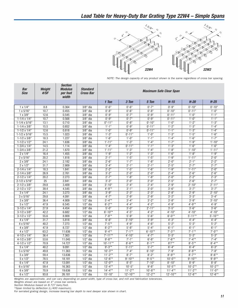
4"2"
CL
CL CL
CL
CLCL
CLCL
11/16"
11/16"
11W4 11W2
NOTE: The design capacity of any product shown is the same regardless of cross bar spacing.

1 x 1/4" 12.2 0.533 3/8" dia 0'-8" 0'-7" 0'-8" 0'-10" 1'-0" 1'-0"1 x 5/16" 14.9 0.667 3/8" dia 0'-9" 0'-8" 0'-9" 1'-0" 1'-1" 1'-2"1 x 3/8" 17.7 0.80 3/8" dia 0'-11" 0'-9" 0'-10" 1'-1" 1'-3" 1'-3"
1-1/4 x 1/4" 14.9 0.833 3/8" dia 0'-11" 0'-9" 0'-10" 1'-1" 1'-3" 1'-4"1-1/4 x 5/16" 18.4 1.042 3/8" dia 1'-1" 0'-10" 1'-0" 1'-3" 1'-5" 1'-5"1-1/4 x 3/8" 21.8 1.250 3/8" dia 1'-4" 1'-0" 1'-1" 1'-4" 1'-6" 1'-7"1-1/2 x 1/4" 17.7 1.20 3/8" dia 1'-3" 0'-11" 1'-1" 1'-4" 1'-6" 1'-7"1-1/2 x 5/16" 21.8 1.50 3/8" dia 1'-7" 1'-1" 1'-3" 1'-6" 1'-8" 1'-9"1-1/2 x 3/8" 26 1.80 3/8" dia 1'-10" 1'-3" 1'-5" 1'-8" 1'-10" 1'-11"1-1/2 x 1/2" 34.3 2.40 3/8" dia 2'-5" 1'-7" 1'-8" 2'-0" 2'-2"* 2'-3"*1-3/4 x 1/4" 20.5 1.633 3/8" dia 1'-8" 1'-2" 1'-3" 1'-7" 1'-9" 1'-10"1-3/4 x 3/8" 30.1 2.450 3/8" dia 2'-6" 1'-8" 1'-9" 2'-1" 2'-3" 2'-4"
2 x 1/4" 23.2 2.133 3/8" dia 2'-2" 1'-6" 1'-7" 1'-10" 2'-0" 2'-1"2 x 5/16" 28.7 2.667 3/8" dia 2'-8" 1'-9" 1'-10" 2'-2" 2'-4" 2'-5"2 x 3/8" 34.3 3.20 3/8" dia 3'-2" 2'-1" 2'-1" 2'-6" 2'-8" 2'-9"2 x 1/2" 45.3 4.267 3/8" dia 3'-10"* 2'-8" 2'-8" 3'-1"* 3'-2"* 3'-2"*
2-1/4 x 1/4" 26.0 2.70 3/8" dia 2'-8" 1'-9" 1'-10" 2'-3" 2'-4" 2'-5"2-1/4 x 3/8" 38.4 4.050 3/8" dia 3'-11"* 2'-7" 2'-7" 3'-0" 3'-2" 3'-3"2-1/2 x 1/4" 28.7 3.333 3/8" dia 3'-4" 2'-2" 2'-2" 2'-7" 2'-9" 2'-10"2-1/2 x 5/16" 35.6 4.167 3/8" dia 4'-1" 2'-7" 2'-10" 3'-1" 3'-3" 3'-3"2-1/2 x 3/8" 42.6 5.00 3/8" dia 4'-7"* 3'-1" 3'-1" 3'-7" 3'-9" 3'-9"2-1/2 x 1/2" 56.4 6.667 3/8" dia 5'-4"* 4'-0" 3'-11" 4'-4"* 4'-4"* 4'-4"*
3 x 1/4" 35.2 4.80 3/8" dia 4'-8" 3'-0" 3'-0" 3'-6" 3'-7" 3'-8"3 x 5/16" 43.4 6.00 1/2" dia 5'-6"* 3'-8" 3'-7" 4'-2" 4'-4" 4'-4"3 x 3/8" 51.7 7.20 1/2" dia 6'-1"* 4'-2" 4'-3"* 4'-11"* 4'-10"* 4'-10'*3 x 1/2" 68.3 9.60 1/2" dia 7'-0"* 5'-5"* 5'-3"* 5'-7"* 5'-7"* 5'-7"*
3-1/2 x 1/4" 40.7 6.533 1/2" dia 6'-2" 3'-11" 3'-11" 4'-6" 4'7" 4'-8"3-1/2 x 3/8" 60 9.800 1/2" dia 7'-6"* 5'-9" 5'-7" 6'-1" 6'-1"* 6'0"*3-1/2 x 1/2" 79.4 13.067 1/2" dia 8'-7"* 6'-7"* 6'-7"* 7'-0"* 7'-0"* 6'-10"*
4 x 1/4" 46.2 8.533 1/2" dia 7'-6"* 5'-1" 4'-11" 5'-9" 5'-9" 5'-10"4 x 5/16" 57.3 10.667 1/2" dia 8'-4"* 6'-3" 6'-1" 6'-9"* 6'-9"* 6'-8'*4 x 3/8" 68.3 12.80 1/2" dia 9'-0"* 7'-0"* 7'-0"* 7'-5"* 7'-4"* 7'-3"*4 x 1/2" 90.4 17.07 1/2" dia 10'-4"* 8'-2"* 7'-11"* 8'-6"* 8'-4"* 8'-4"*
4-1/2 x 1/4" 51.7 10.80 1/2" dia 8'-10"* 6'-4" 6'-2" 7'-1" 7'-1" 7'-1"4-1/2 x 3/8" 76.6 16.20 1/2" dia 10'-8"* 8'-4"* 8'-2"* 8'-9"* 8'-8"* 8'-7"*4-1/2 x 1/2" 101.5 21.60 1/2" dia 12'-0"* 9'-2"* 9'-4"* 10'-0"* 9'-0"* 9'-11"*
5 x 1/4" 57.3 13.333 1/2" dia 10'-4"* 7'-9" 7'-6" 8'-5"* 8'-5"* 8'-2"*5 x 5/16" 71.1 16.667 1/2" dia 11'-4"* 8'-10"* 8'-9"* 9'-4"* 9'-3"* 9'-2"*5 x 3/8" 84.9 20.0 1/2" dia 12'-8"* 9'-10"* 9'-7"* 10'-2"* 10'-1"* 10'-0"*5 x 1/2" 112.5 26.667 1/2" dia 13-10"* 10'-4"* 10'-10"* 11'-7"* 11'-6"* 11'-4"*6 x 1/4" 68.3 19.20 1/2" dia 13'-4"* 10'-2"* 10'-2"* 11'-0"* 10'10"* 10'-8"*6 x 5/16" 84.9 24.0 1/2" dia 14'-6"* 11'-2"* 11'-4"* 12'-2"* 12'-0"* 11'-11"*6 x 3/8" 101.4 28.80 1/2" dia 15'-10"* 12'-0"* 12'-4"* 13'-2"* 13'-0"* 12'-10"*6 x 1/2" 134.6 38.40 1/2" dia 16'-8"* 14'-4'* 14'-0"* 14'-10"* 14'-6"* 14'-6"*
9999
Maximum Safe Clear SpanBarSize
Weight#/SF
SectionModulus per foot width
StandardCross Bar
1 Ton 3 Ton 5 Ton H-15 H-20 H-25
Load Table for Heavy-Duty Bar Grating Type 15W4 – Simple Spans
Weights are approximate, and can vary depending on panel width, type of cross bar, and mill and fabrication tolerances.Weights shown are based on 4" cross bar centers.Section Modulus based on 12.8 bars/foot.*Span limited by deflection (L/400 maximum).For serrated grating design, increase bearing bar depth to next deeper size shown in chart.
CL
CL
CL
CL
CLCL
CL CL
15/16"
15/16"
4"2"
15W4 15W2
NOTE: The design capacity of any product shown is the same regardless of cross bar spacing.
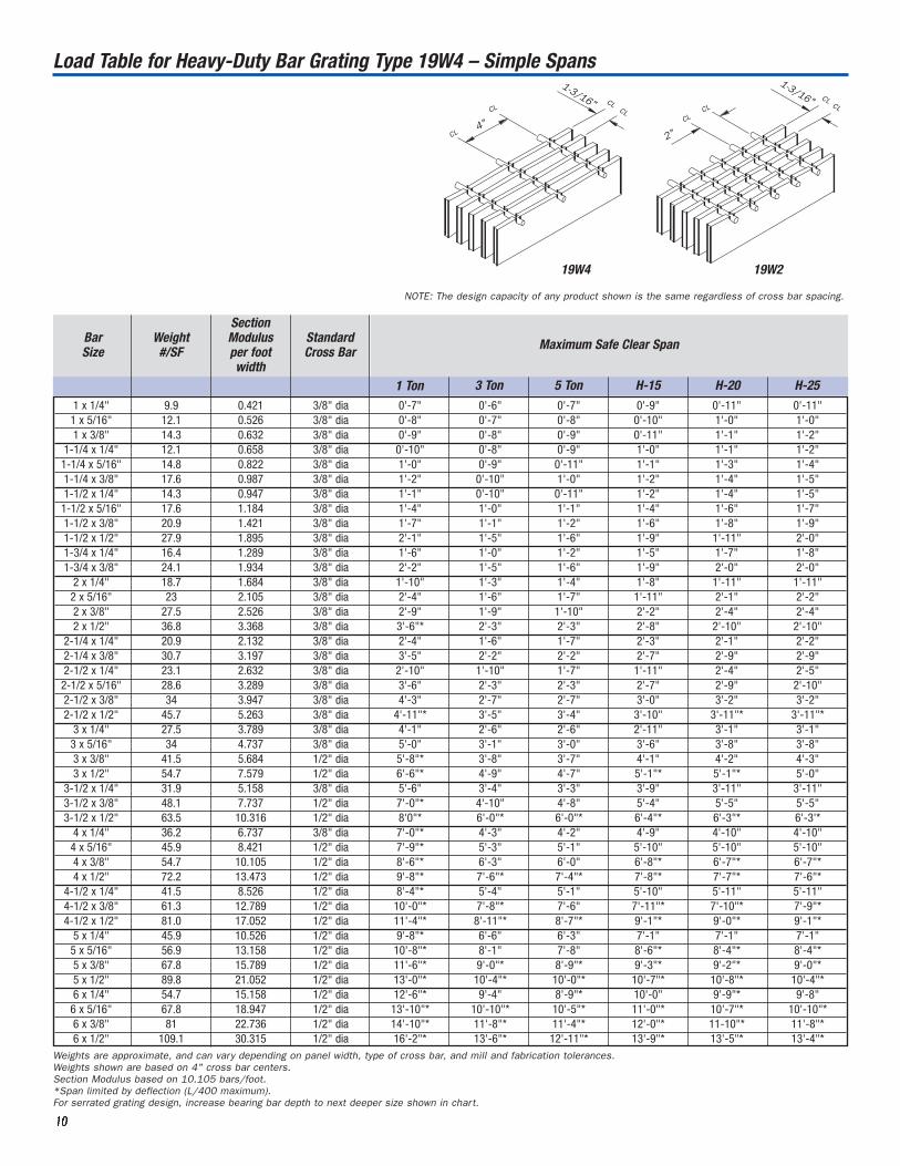
Load Table for Heavy-Duty Bar Grating Type 19W4 – Simple Spans
11110000
1 x 1/4" 9.9 0.421 3/8" dia 0'-7" 0'-6" 0'-7" 0'-9" 0'-11" 0'-11"1 x 5/16" 12.1 0.526 3/8" dia 0'-8" 0'-7" 0'-8" 0'-10" 1'-0" 1'-0"1 x 3/8" 14.3 0.632 3/8" dia 0'-9" 0'-8" 0'-9" 0'-11" 1'-1" 1'-2"
1-1/4 x 1/4" 12.1 0.658 3/8" dia 0'-10" 0'-8" 0'-9" 1'-0" 1'-1" 1'-2"1-1/4 x 5/16" 14.8 0.822 3/8" dia 1'-0" 0'-9" 0'-11" 1'-1" 1'-3" 1'-4"1-1/4 x 3/8" 17.6 0.987 3/8" dia 1'-2" 0'-10" 1'-0" 1'-2" 1'-4" 1'-5"1-1/2 x 1/4" 14.3 0.947 3/8" dia 1'-1" 0'-10" 0'-11" 1'-2" 1'-4" 1'-5"1-1/2 x 5/16" 17.6 1.184 3/8" dia 1'-4" 1'-0" 1'-1" 1'-4" 1'-6" 1'-7"1-1/2 x 3/8" 20.9 1.421 3/8" dia 1'-7" 1'-1" 1'-2" 1'-6" 1'-8" 1'-9"1-1/2 x 1/2" 27.9 1.895 3/8" dia 2'-1" 1'-5" 1'-6" 1'-9" 1'-11" 2'-0"1-3/4 x 1/4" 16.4 1.289 3/8" dia 1'-6" 1'-0" 1'-2" 1'-5" 1'-7" 1'-8"1-3/4 x 3/8" 24.1 1.934 3/8" dia 2'-2" 1'-5" 1'-6" 1'-9" 2'-0" 2'-0"
2 x 1/4" 18.7 1.684 3/8" dia 1'-10" 1'-3" 1'-4" 1'-8" 1'-11" 1'-11"2 x 5/16" 23 2.105 3/8" dia 2'-4" 1'-6" 1'-7" 1'-11" 2'-1" 2'-2"2 x 3/8" 27.5 2.526 3/8" dia 2'-9" 1'-9" 1'-10" 2'-2" 2'-4" 2'-4"2 x 1/2" 36.8 3.368 3/8" dia 3'-6"* 2'-3" 2'-3" 2'-8" 2'-10" 2'-10"
2-1/4 x 1/4" 20.9 2.132 3/8" dia 2'-4" 1'-6" 1'-7" 2'-3" 2'-1" 2'-2"2-1/4 x 3/8" 30.7 3.197 3/8" dia 3'-5" 2'-2" 2'-2" 2'-7" 2'-9" 2'-9"2-1/2 x 1/4" 23.1 2.632 3/8" dia 2'-10" 1'-10" 1'-7" 1'-11" 2'-4" 2'-5"2-1/2 x 5/16" 28.6 3.289 3/8" dia 3'-6" 2'-3" 2'-3" 2'-7" 2'-9" 2'-10"2-1/2 x 3/8" 34 3.947 3/8" dia 4'-3" 2'-7" 2'-7" 3'-0" 3'-2" 3'-2"2-1/2 x 1/2" 45.7 5.263 3/8" dia 4'-11"* 3'-5" 3'-4" 3'-10" 3'-11"* 3'-11"*
3 x 1/4" 27.5 3.789 3/8" dia 4'-1" 2'-6" 2'-6" 2'-11" 3'-1" 3'-1"3 x 5/16" 34 4.737 3/8" dia 5'-0" 3'-1" 3'-0" 3'-6" 3'-8" 3'-8"3 x 3/8" 41.5 5.684 1/2" dia 5'-8"* 3'-8" 3'-7" 4'-1" 4'-2" 4'-3"3 x 1/2" 54.7 7.579 1/2" dia 6'-6"* 4'-9" 4'-7" 5'-1"* 5'-1"* 5'-0"
3-1/2 x 1/4" 31.9 5.158 3/8" dia 5'-6" 3'-4" 3'-3" 3'-9" 3'-11" 3'-11"3-1/2 x 3/8" 48.1 7.737 1/2" dia 7'-0"* 4'-10" 4'-8" 5'-4" 5'-5" 5'-5"3-1/2 x 1/2" 63.5 10.316 1/2" dia 8'0"* 6'-0"* 6'-0"* 6'-4"* 6'-3"* 6'-3'*
4 x 1/4" 36.2 6.737 3/8" dia 7'-0"* 4'-3" 4'-2" 4'-9" 4'-10" 4'-10"4 x 5/16" 45.9 8.421 1/2" dia 7'-9"* 5'-3" 5'-1" 5'-10" 5'-10" 5'-10"4 x 3/8" 54.7 10.105 1/2" dia 8'-6"* 6'-3" 6'-0" 6'-8"* 6'-7"* 6'-7"*4 x 1/2" 72.2 13.473 1/2" dia 9'-8"* 7'-6"* 7'-4"* 7'-8"* 7'-7"* 7'-6"*
4-1/2 x 1/4" 41.5 8.526 1/2" dia 8'-4"* 5'-4" 5'-1" 5'-10" 5'-11" 5'-11"4-1/2 x 3/8" 61.3 12.789 1/2" dia 10'-0"* 7'-8"* 7'-6" 7'-11"* 7'-10"* 7'-9"*4-1/2 x 1/2" 81.0 17.052 1/2" dia 11'-4"* 8'-11"* 8'-7"* 9'-1"* 9'-0"* 9'-1"*
5 x 1/4" 45.9 10.526 1/2" dia 9'-8"* 6'-6" 6'-3" 7'-1" 7'-1" 7'-1"5 x 5/16" 56.9 13.158 1/2" dia 10'-8"* 8'-1" 7'-8" 8'-6"* 8'-4"* 8'-4"*5 x 3/8" 67.8 15.789 1/2" dia 11'-6"* 9'-0"* 8'-9"* 9'-3"* 9'-2"* 9'-0"*5 x 1/2" 89.8 21.052 1/2" dia 13'-0"* 10'-4"* 10'-0"* 10'-7"* 10'-8"* 10'-4"*6 x 1/4" 54.7 15.158 1/2" dia 12'-6"* 9'-4" 8'-9"* 10'-0" 9'-9"* 9'-8" 6 x 5/16" 67.8 18.947 1/2" dia 13'-10"* 10'-10"* 10'-5"* 11'-0"* 10'-7"* 10'-10"*6 x 3/8" 81 22.736 1/2" dia 14'-10"* 11'-8"* 11'-4"* 12'-0"* 11-10"* 11'-8"*6 x 1/2" 109.1 30.315 1/2" dia 16'-2"* 13'-6"* 12'-11"* 13'-9"* 13'-5"* 13'-4"*
Maximum Safe Clear SpanBarSize
Weight#/SF
SectionModulus per foot width
StandardCross Bar
1 Ton 3 Ton 5 Ton H-15 H-20 H-25
Weights are approximate, and can vary depending on panel width, type of cross bar, and mill and fabrication tolerances.Weights shown are based on 4" cross bar centers.Section Modulus based on 10.105 bars/foot.*Span limited by deflection (L/400 maximum).For serrated grating design, increase bearing bar depth to next deeper size shown in chart.
4"
1-3/16"
1-3/16"
2"CL
CL
CLCLCL
CLCL
CL
19W4 19W2
NOTE: The design capacity of any product shown is the same regardless of cross bar spacing.
Maximum Safe Clear SpanBarSize
Weight#/SF
SectionModulus per foot width
StandardCross Bar
1 Ton 3 Ton 5 Ton H-15 H-20 H-25
Load Table for Heavy-Duty Bar Grating Type 22W4 – Simple Spans
Weights are approximate, and can vary depending on panel width, type of cross bar, and mill and fabrication tolerances. Weights shown are based on 4" cross bar centers.Section Modulus based on 8.727 bars/foot.*Span limited by deflection (L/400 maximum).For serrated grating design, increase bearing bar depth to next deeper size shown in chart.
11111111
1 x 1/4" 8.8 0.364 3/8" dia 0'-6" 0'-6" 0'-7" 0'-9" 0'-10" 0'-10"1 x 5/16" 10.7 0.455 3/8" dia 0'-8" 0'-6" 0'-8" 0'-10" 0'-11" 1'-0"1 x 3/8" 12.6 0.545 3/8" dia 0'-9" 0'-7" 0'-9" 0'-11" 1'-0" 1'-1"
1-1/4 x 1/4" 10.7 0.568 3/8" dia 0'-9" 0'-7" 0'-9" 0'-11" 1'-0" 1'-1"1-1/4 x 5/16" 13.1 0.710 3/8" dia 0"-11" 0'-8" 0'-10" 1'-0" 1'-2" 1'-3"1-1/4 x 3/8" 15.5 0.852 3/8" dia 1'-1" 0'-9" 0'-11" 1'-2" 1'-3" 1'-4"1-1/2 x 1/4" 12.6 0.818 3/8" dia 1'-0" 0'-9" 0'-11" 1'-1" 1'-3" 1'-4"1-1/2 x 5/16" 15.5 1.023 3/8" dia 1'-3" 0'-11" 1'-0" 1'-3" 1'-5" 1'-6"1-1/2 x 3/8" 18.3 1.227 3/8" dia 1'-6" 1'-0" 1'-1" 1'-4" 1'-6" 1'-7"1-1/2 x 1/2" 24.1 1.636 3/8" dia 1'-11" 1'-3" 1'-4" 1'-7" 1'-9" 1'-10"1-3/4 x 1/4" 14.5 1.114 3/8" dia 1'-4" 0'-11" 1'-1" 1'-3" 1'-6" 1'-6"1-3/4 x 3/8" 21.2 1.670 3/8" dia 1'-11" 1'-3" 1'-4" 1'-8" 1'-10" 1'-11"
2 x 1/4" 16.4 1.455 3/8" dia 1'-9" 1'-2" 1'-3" 1'-6" 1'-8" 1'-9"2 x 5/16" 20.2 1.818 3/8" dia 2'-1" 1'-5" 1'-5" 1'-9" 1'-11" 2'-0"2 x 3/8" 24.1 2.182 3/8" dia 2'-6" 1'-7" 1'-8" 2'-0" 2'-1" 2'-2"2 x 1/2" 31.7 2.909 3/8" dia 3'-4" 2'-1" 2'-1" 2'-5" 2'-7" 2'-7"
2-1/4 x 1/4" 18.3 1.841 3/8" dia 2'-2" 1'-5" 1'-6" 1'-9" 1'-11" 2'-0"2-1/4 x 3/8" 26.9 2.761 3/8" dia 3'-2" 2'-0" 2'-0" 2'-4" 2'-6" 2'-6"2-1/2 x 1/4" 20.2 2.273 3/8" dia 2'-7" 1'-8" 1'-8" 2'-0" 2'-2" 2'-3"2-1/2 x 5/16" 25 2.841 3/8" dia 3'-3" 2'-0" 2'-0" 2'-5" 2'-6" 2'-7"2-1/2 x 3/8" 29.8 3.409 3/8" dia 3'-10" 2'-4" 2'-4" 2'-9" 2'-10" 2'-11"2-1/2 x 1/2" 39.4 4.545 3/8" dia 4'-9"* 3'-1" 3'-0" 3'-6" 3'-7" 3'-7"
3 x 1/4" 24.1 3.273 3/8" dia 3'-9" 2'-3" 2'-3" 2'-8" 2'-9" 2'-10"3 x 5/16" 29.8 4.091 3/8" dia 4'-7" 2'-9" 2'-9" 3'-2" 3'-3" 3'-4"3 x 3/8" 36.4 4.909 1/2" dia 5'-4"* 3'-4" 3'-2" 3'-8" 3'-9" 3'-10"3 x 1/2" 47.9 6.545 1/2" dia 6'-2"* 4'-4" 4'-2" 4'-9" 4'-9"* 4'-9"
3-1/2 x 1/4" 27.9 4.454 3/8" dia 5'-0" 3'-0" 2'-11" 3'-5" 3'-6" 3'-6"3-1/2 x 3/8" 42.2 6.682 1/2" dia 6'-10"* 4'-5" 4'-2" 4'-10" 4'-10" 4'-10"3-1/2 x 1/2" 55.6 8.909 1/2" dia 7'-8"* 5'-9" 5'-6" 6'-0"* 5'-11"* 5'-10"*
4 x 1/4" 31.7 5.818 3/8" dia 6'-6" 3'-10" 3'-9" 4'-3" 4'-4" 4'-4"4 x 5/16" 40.2 7.273 1/2" dia 7'-5"* 4'-9" 4'-6" 5'-2" 5'-3" 5'-2"4 x 3/8" 47.9 8.727 1/2" dia 8'-2"* 5'-8" 5'-4" 6'-1" 6'-1" 6'-1"4 x 1/2" 63.2 11.636 1/2" dia 9'-4"* 7'-1"* 6'-10"* 7'-3"* 7'-1"* 7'-0"*
4-1/2 x 1/4" 36.4 7.363 1/2" dia 7'-11"* 4'-10" 4'-7" 5'-3" 5'-3" 5'-3"4-1/2 x 3/8" 53.6 11.045 1/2" dia 9'-8"* 7'-1" 6'-8" 7'-6"* 7'-4"* 7'-4"4-1/2 x 1/2" 70.9 14.727 1/2" dia 10'-11"* 8'-6"* 8'-1"* 8'7"* 8'-5"* 8'-4"*
5 x 1/4" 40.2 9.091 1/2" dia 9'-3"* 5'-11" 5'-7" 6'-4" 6'-4" 6'-3"5 x 5/16" 49.8 11.363 1/2" dia 10'-3"* 7'-4" 6'-10" 7'-9" 8'-8"* 7'-8"5 x 3/8" 59.4 13.636 1/2" dia 11'-2"* 8'-7" 8'-2" 8'-9"* 8'-7"* 8'-6"*5 x 1/2" 78.5 18.181 1/2" dia 12'-6"* 9'-10"* 9'-5"* 10'-0"* 9'-10"* 9'-9"*6 x 1/4" 47.9 13.091 1/2" dia 12'-0"* 8'-5" 7'-10" 8'-10" 8'-9" 8'-8"6 x 5/16" 59.4 16.363 1/2" dia 13'-4"* 10'-5" 9'-8" 10'-5"* 10'-2"* 10'-2"*6 x 3/8" 70.9 19.636 1/2" dia 14'-4"* 11'-2"* 10'-8"* 11'-4"* 11'-2"* 11'-0'*6 x 1/2" 93.8 26.181 1/2" dia 15'-10" 12'-10"* 12'-2"* 12'-10"* 12'-8"* 12'-6"*
4"
2"
1-3/8"
1-3/8"
CL
CL CL
CL
CL CLCLCL
22W4 22W2
NOTE: The design capacity of any product shown is the same regardless of cross bar spacing.
1 x 1/4" 6.9 0.267 3/8" dia 0'-6" 0'-5" 0'-6" 0'-8" 0'-9" 0'-9"1 x 5/16" 8.3 0.333 3/8" dia 0'-7" 0'-6" 0'-7" 0'-9" 0'-10" 0'-10"1 x 3/8" 9.8 0.40 3/8" dia 0'-8" 0'-6" 0'-8" 0'-9" 0'-11" 0'-11"
1-1/4 x 1/4" 8.3 0.417 3/8" dia 0'-8" 0'-6" 0'-8" 0'-10" 0'-11" 0'-11"1-1/4 x 5/16" 10.2 0.521 3/8" dia 0'-9" 0'-7" 0'-9" 0'-11" 1'-0" 1'-1"1-1/4 x 3/8" 12 0.625 3/8" dia 0'-11" 0'-8" 0'-10" 1'-0" 1'-1" 1'-2"1-1/2 x 1/4" 9.8 0.60 3/8" dia 0'-11" 0'-8" 0'-9" 1'-0" 1'-1" 1'-2"1-1/2 x 5/16" 12 0.750 3/8" dia 1'-1" 0'-9" 0'-11" 1'-1" 1'-3" 1'-3"1-1/2 x 3/8" 14.1 0.90 3/8" dia 1'-3" 0'-10" 1'-0" 1'-2" 1'-4" 1'-5"1-1/2 x 1/2" 18.4 1.20 3/8" dia 1'-8" 1'-1" 1'-2" 1'-5" 1'-7" 1'-7"1-3/4 x 1/4" 11.2 0.817 3/8" dia 1'-2" 0'-10" 0'-11" 1'-2" 1'-3" 1'-4"1-3/4 x 3/8" 16.3 1.225 3/8" dia 1'-8" 1'-1" 1'-2" 1'-5" 1'-7" 1'-8"
2 x 1/4" 12.7 1.067 3/8" dia 1'-6" 1'-0" 1'-1" 1'-4" 1'-6" 1'-6"2 x 5/16" 15.6 1.333 3/8" dia 1'-10" 1'-2" 1'-3" 1'-6" 1'-8" 1'-9"2 x 3/8" 18.5 1.60 3/8" dia 2'-2" 1'-4" 1'-5" 1'-8" 1'-10" 1'-11"2 x 1/2" 24.2 2.133 3/8" dia 2'-10" 1'-9" 1'-9" 2'-0" 2'-2" 2'-2"
2-1/4 x 1/4" 14.1 1.350 3/8" dia 1'-10" 1'-2" 1'-3' 1'-6" 1'-8" 1'-9"2-1/4 x 3/8" 20.6 2.025 3/8" dia 2'-10" 1'-8" 1'-8" 1'-11" 2'-1" 2'-2"2-1/2 x 1/4" 15.6 1.667 3/8" dia 2'-3" 1'-5" 1'-5" 1'-8" 1'-10" 1'-11"2-1/2 x 5/16" 19.2 2.083 3/8" dia 2'-9" 1'-8" 1'-8" 2'-0" 2'-1" 2'-2"2-1/2 x 3/8" 22.8 2.50 3/8" dia 3'-3" 2'-0" 1'-11" 2'-3" 2'-5" 2'-5"2-1/2 x 1/2" 30.0 3.333 3/8" dia 4'-4" 2'-6" 2'-5" 2'-10" 2'-11" 2'-11"
3 x 1/4" 18.5 2.40 3/8" dia 3'-2" 1'-9" 1'-11' 2'-2" 2'-4" 2'-4"3 x 5/16" 22.8 3.0 3/8" dia 3'-11" 2'-4" 2'-3" 2'-7" 2'-8" 2'-9"3 x 3/8" 28.0 3.60 1/2" dia 4'-8" 2'-9" 2'-7" 3'-0" 3'-1" 3'-1"3 x 1/2" 36.7 4.80 1/2" dia 5'-8"* 3'-6" 3'-4" 3'-9" 3'-10" 3'-10"
3-1/2 x 1/4" 21.4 3.267 3/8" dia 4'-3" 2'-6" 2'-5" 2'-9" 2'-10" 2'-11"3-1/2 x 3/8" 32.3 4.90 1/2" dia 6'-2"* 3'-5" 3'-5" 3'-10" 3'-11" 3'-11"3-1/2 x 1/2" 42.5 6.533 1/2" dia 7'-2"* 4'-9" 4'-5" 4'-11" 4'-11" 4'-11"
4 x 1/4" 24.2 4.267 3/8" dia 5'-6" 3'-2" 3'-0" 3'-5" 3'-6" 3'-6"4 x 5/16" 30.9 5.333 1/2" dia 6'-10" 3'-11" 3'-8" 4'-2" 4'-2" 4'-2"4 x 3/8" 36.7 6.40 1/2" dia 7'-6"* 4'-8" 4'-4" 4'-10" 4'-10" 4'-10"4 x 1/2" 48.2 8.533 1/2" dia 8'-7"* 6'-1" 5'-7" 6'-3" 6'-2" 6'-2"
4-1/2 x 1/4" 28.0 5.40 1/2" dia 6'-11" 3'-11" 3'-8" 4'-2" 4'-3" 4'-3"4-1/2 x 3/8" 41.0 8.10 1/2" dia 8'-10"* 5'-10" 5'-4" 6'-0" 5'-11" 5'-10"4-1/2 x 1/2" 54.0 10.80 1/2" dia 10'-2"* 7'-8" 7'-0" 7'-7"* 7'-5"* 7'-4"*
5 x 1/4" 30.9 6.667 1/2" dia 8'-6" 4'-10" 4'-6" 5'-0" 5'-0" 5'-0"5 x 5/16" 38.1 8.333 1/2" dia 9'-6"* 5'-11" 5'-6" 6'-2" 6'-1" 6'-0"5 x 3/8" 45.4 10.0 1/2" dia 10'-4"* 7'-1" 6'-6" 7'-3" 7'-2" 7'-0"5 x 1/2" 59.8 13.33 1/2" dia 11'-9"* 8'-11"* 8'-5" 8'-10"* 8'-8"* 8'-7"*6 x 1/4" 36.7 9.60 1/2" dia 11'-2"* 6'-10" 6'-3" 7'-0" 6'-11" 6'-10"6 x 5/16" 45.4 12.0 1/2" dia 12'-4"* 8'-6" 7'-9" 8'-7" 8'-5" 8'-3"6 x 3/8" 54.0 14.40 1/2" dia 13'-3"* 10'-1" 9'-2" 9'-11"* 9'-10" 9'-9"6 x 1/2" 71.4 19.20 1/2" dia 15'-0"* 11'-8"* 11'-0"* 11'-6"* 11'-3"* 11'-1"*
Maximum Safe Clear SpanBarSize
Weight#/SF
SectionModulus per foot width
StandardCross Bar
1 Ton 3 Ton 5 Ton H-15 H-20 H-25
11112222
Weights are approximate, and can vary depending on panel width, type of cross bar, and mill and fabrication tolerances. Weights shown are based on 4" cross bar centers.Section Modulus based on 6.4 bars/foot.*Span limited by deflection (L/400 maximum).For serrated grating design, increase bearing bar depth to next deeper size shown in chart.
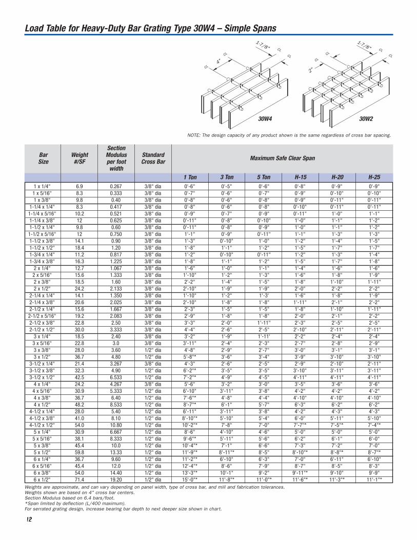
4"
2"CL
CL
CL
CLCL
CL CL
CL
1-7/8"1-7/8"
30W4 30W2
NOTE: The design capacity of any product shown is the same regardless of cross bar spacing.
Load Table for Heavy-Duty Bar Grating Type 30W4 – Simple Spans

1 x 1/4" 5.7 0.211 3/8" dia 0'-5" 0'-5" 0'-6" 0'-7" 0'-8" 0'-8"1 x 5/16" 6.8 0.263 3/8" dia 0'-6" 0'-5" 0'-6" 0'-8" 0'-9" 0'-9"1 x 3/8" 7.9 0.316 3/8" dia 0'-7" 0'-6" 0'-7" 0'-8" 0'-10" 0'-10"
1-1/4 x 1/4" 6.8 0.329 3/8" dia 0'-7" 0'6" 0'-7" 0'-9" 0'-10" 0'-10"1-1/4 x 5/16" 8.2 0.411 3/8" dia 0'-9" 0'-6" 0'-8" 0'-10" 0'-11" 0'-11"1-1/4 x 3/8" 9.6 0.493 3/8" dia 0'-10" 0'-7" 0'-9" 0'-11" 1'-0" 1'-1"1-1/2 x 1/4" 7.9 0.474 3/8" dia 0'-10" 0'7" 0'-9" 0'-11" 1'-0" 1'-0"1-1/2 x 5/16" 9.6 0.592 3/8" dia 1'-0" 0'-8" 0'-10" 1'-0" 1'-1" 1'-2"1-1/2 x 3/8" 11.3 0.711 3/8" dia 1'-2" 0'-9" 0'-11" 1'-1" 1'-3" 1'-3"1-1/2 x 1/2" 14.7 0.947 3/8" dia 1'-6" 1'-0" 1'-0" 1'-3" 1'-5" 1'-6"1-3/4 x 1/4" 9 0.645 3/8" dia 1'-1" 0'9" 0'-10" 1'-0" 1'-2" 1'-2"1-3/4 x 3/8" 13 0.967 3/8" dia 1'-6" 1'-0" 1'-1" 1'-3" 1'-5" 1'-6"
2 x 1/4" 10.2 0.842 3/8" dia 1'-4" 0'-11" 1'-0" 1'-2" 1'-4" 1'-5"2 x 5/16" 12.5 1.053 3/8" dia 1'-7" 1'-0" 1'-1" 1'-4" 1'-6" 1'-7"2 x 3/8" 14.7 1.263 3/8" dia 1'-11" 1'-2" 1'-3" 1'-6" 1'-8" 1'-8"2 x 1/2" 19.2 1.684 3/8" dia 2'-6" 1'-6" 1'-6" 1'-9" 1'-11" 2'-0"
2-1/4 x 1/4" 11.3 1.066 3/8" dia 1'-8" 1'-1" 1'-1" 1'-4" 1'-6" 1'-7"2-1/4 x 3/8" 16.4 1.599 3/8" dia 2'-5" 1'-5" 1'-5" 1'-9" 1'-10" 1'-11"2-1/2 x 1/4" 12.5 1.316 3/8" dia 2'-0" 1'-3" 1'-3" 1'-5" 1'-8" 1'-9"2-1/2 x 5/16" 15.3 1.645 3/8" dia 2'-6" 1'-6" 1'-6" 1'-9" 1'-11" 1'-11"2-1/2 x 3/8" 18.1 1.974 3/8" dia 2'-11" 1'-9" 1'-8" 2'-0" 2'-1" 2'-2"2-1/2 x 1/2" 23.8 2.632 3/8" dia 3'-6" 2'-3" 2'-2" 2'-5" 2'-6" 2'-7"
3 x 1/4" 14.7 1.895 3/8" dia 2'-10" 1'-8" 1'-8" 1'-11" 2'-1" 2'-1"3 x 5/16" 18.1 2.368 3/8" dia 3'-6" 2'-0" 1'-11" 2'-3" 2'-4" 2'-5"3 x 3/8" 22.4 2.842 1/2" dia 4'-2" 2'-5" 2'-3" 2'-7" 2'-10" 2'-8"3 x 1/2" 29.2 3.790 1/2" dia 5'-4"* 3'-1" 2'-11" 3'-3" 3'-4" 3'-4"
3-1/2 x 1/4" 17 2.579 3/8" dia 3'-9" 2'-2" 2'-1" 2'-5" 2'-6" 2'-6"3-1/2 x 3/8" 25.8 3.869 1/2" dia 5'-7" 3'-2" 2'-11" 3'-4" 3'-4" 3'-4"3-1/2 x 1/2" 33.7 5.158 1/2" dia 6'-9'* 4'-1" 3'-9" 4'-3" 4'-2" 4'-2"
4 x 1/4" 19.2 3.369 3/8" dia 4'-11" 2'-9" 2'-7" 2'-11" 3'-0" 3'-0"4 x 5/16" 24.7 4.211 1/2" dia 6'-1" 3'-5" 3'-2" 3'-7" 3'-7" 3'-7"4 x 3/8" 29.2 5.053 1/2" dia 7'-2"* 4'-0" 3'-8" 4'-2" 4'-2" 4'-1"4 x 1/2" 38.2 6.737 1/2" dia 8'-2"* 5'-4" 4'-10" 5'-4" 5'-3" 5'-2"
4-1/2 x 1/4" 22.4 4.263 1/2" dia 6'-2" 3'-5" 3'-2" 3'-7" 3'-7" 3'-7"4-1/2 x 3/8" 32.6 6.395 1/2" dia 8'-5"* 5'-0" 4'-7" 5'-1" 5'-0" 5'-0"4-1/2 x 1/2" 42.8 8.527 1/2" dia 9'-7"* 6'-8" 6'-0" 6'-7" 6'-5" 6'-4"
5 x 1/4" 24.7 5.264 1/2" dia 7'-7" 4'-2" 3'-10" 4'-3" 4'-3" 4'-3"5 x 5/16" 30.3 6.579 1/2" dia 9'-0"* 5'-2" 4'-8" 5'-3" 5'-2" 5'-1"5 x 3/8" 36 7.895 1/2" dia 9'-10"* 6'-2" 5'-7" 6'-2" 6'-0" 5'-11"5 x 1/2" 47.3 10.527 1/2" dia 11'-2"* 8'-2" 7'-3" 8'-0" 7'-9" 7'-7"6 x 1/4" 29.2 7.580 1/2" dia 10'-6"* 5'-11" 5'-4" 5'-11" 5'-10" 5'-9"6 x 5/16" 36 9.474 1/2" dia 11'-8"* 7'-4" 6'-7" 7'-3" 7'-1" 6'-11"6 x 3/8" 42.8 11.369 1/2" dia 12'-8"* 8'-9" 7'-10" 8'-7" 8'-4" 8'-1"6 x 1/2" 56.4 15.159 1/2" dia 14'-4"* 10'-10"* 10'-2"* 10'-7"* 10'-3"* 10'-1"*
Maximum Safe Clear SpanBarSize
Weight#/SF
SectionModulus per foot width
StandardCross Bar
1 Ton 3 Ton 5 Ton H-15 H-20 H-25
11113333
Weights are approximate, and can vary depending on panel width, type of cross bar, and mill and fabrication tolerances.Weights shown are based on 4" cross bar centers.Section Modulus based on 5.053 bars/foot.*Span limited by deflection (L/400 maximum).
4"
2"CL
CL
CL
CLCL
CLCL
CL
2-3/8"
2-3/8"
38W4 38W2
NOTE: The design capacity of any product shown is the same regardless of cross bar spacing.
Load Table for Heavy-Duty Bar Grating Type 38W4 – Simple Spans
11114444
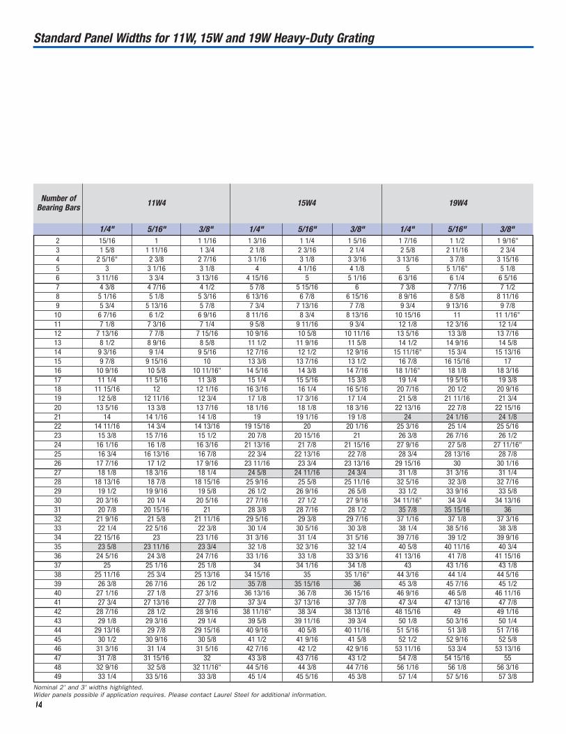
Number ofBearing Bars 11W4 15W4 19W4
3/8"
Nominal 2' and 3' widths highlighted.Wider panels possible if application requires. Please contact Laurel Steel for additional information.
2 15/16 1 1 1/16 1 3/16 1 1/4 1 5/16 1 7/16 1 1/2 1 9/16"3 1 5/8 1 11/16 1 3/4 2 1/8 2 3/16 2 1/4 2 5/8 2 11/16 2 3/44 2 5/16" 2 3/8 2 7/16 3 1/16 3 1/8 3 3/16 3 13/16 3 7/8 3 15/165 3 3 1/16 3 1/8 4 4 1/16 4 1/8 5 5 1/16" 5 1/86 3 11/16 3 3/4 3 13/16 4 15/16 5 5 1/16 6 3/16 6 1/4 6 5/167 4 3/8 4 7/16 4 1/2 5 7/8 5 15/16 6 7 3/8 7 7/16 7 1/28 5 1/16 5 1/8 5 3/16 6 13/16 6 7/8 6 15/16 8 9/16 8 5/8 8 11/169 5 3/4 5 13/16 5 7/8 7 3/4 7 13/16 7 7/8 9 3/4 9 13/16 9 7/810 6 7/16 6 1/2 6 9/16 8 11/16 8 3/4 8 13/16 10 15/16 11 11 1/16"11 7 1/8 7 3/16 7 1/4 9 5/8 9 11/16 9 3/4 12 1/8 12 3/16 12 1/412 7 13/16 7 7/8 7 15/16 10 9/16 10 5/8 10 11/16 13 5/16 13 3/8 13 7/1613 8 1/2 8 9/16 8 5/8 11 1/2 11 9/16 11 5/8 14 1/2 14 9/16 14 5/814 9 3/16 9 1/4 9 5/16 12 7/16 12 1/2 12 9/16 15 11/16" 15 3/4 15 13/1615 9 7/8 9 15/16 10 13 3/8 13 7/16 13 1/2 16 7/8 16 15/16 1716 10 9/16 10 5/8 10 11/16" 14 5/16 14 3/8 14 7/16 18 1/16" 18 1/8 18 3/1617 11 1/4 11 5/16 11 3/8 15 1/4 15 5/16 15 3/8 19 1/4 19 5/16 19 3/818 11 15/16 12 12 1/16 16 3/16 16 1/4 16 5/16 20 7/16 20 1/2 20 9/1619 12 5/8 12 11/16 12 3/4 17 1/8 17 3/16 17 1/4 21 5/8 21 11/16 21 3/420 13 5/16 13 3/8 13 7/16 18 1/16 18 1/8 18 3/16 22 13/16 22 7/8 22 15/1621 14 14 1/16 14 1/8 19 19 1/16 19 1/8 24 24 1/16 24 1/822 14 11/16 14 3/4 14 13/16 19 15/16 20 20 1/16 25 3/16 25 1/4 25 5/1623 15 3/8 15 7/16 15 1/2 20 7/8 20 15/16 21 26 3/8 26 7/16 26 1/224 16 1/16 16 1/8 16 3/16 21 13/16 21 7/8 21 15/16 27 9/16 27 5/8 27 11/16"25 16 3/4 16 13/16 16 7/8 22 3/4 22 13/16 22 7/8 28 3/4 28 13/16 28 7/826 17 7/16 17 1/2 17 9/16 23 11/16 23 3/4 23 13/16 29 15/16 30 30 1/1627 18 1/8 18 3/16 18 1/4 24 5/8 24 11/16 24 3/4 31 1/8 31 3/16 31 1/428 18 13/16 18 7/8 18 15/16 25 9/16 25 5/8 25 11/16 32 5/16 32 3/8 32 7/1629 19 1/2 19 9/16 19 5/8 26 1/2 26 9/16 26 5/8 33 1/2 33 9/16 33 5/830 20 3/16 20 1/4 20 5/16 27 7/16 27 1/2 27 9/16 34 11/16" 34 3/4 34 13/1631 20 7/8 20 15/16 21 28 3/8 28 7/16 28 1/2 35 7/8 35 15/16 3632 21 9/16 21 5/8 21 11/16 29 5/16 29 3/8 29 7/16 37 1/16 37 1/8 37 3/1633 22 1/4 22 5/16 22 3/8 30 1/4 30 5/16 30 3/8 38 1/4 38 5/16 38 3/834 22 15/16 23 23 1/16 31 3/16 31 1/4 31 5/16 39 7/16 39 1/2 39 9/1635 23 5/8 23 11/16 23 3/4 32 1/8 32 3/16 32 1/4 40 5/8 40 11/16 40 3/436 24 5/16 24 3/8 24 7/16 33 1/16 33 1/8 33 3/16 41 13/16 41 7/8 41 15/1637 25 25 1/16 25 1/8 34 34 1/16 34 1/8 43 43 1/16 43 1/838 25 11/16 25 3/4 25 13/16 34 15/16 35 35 1/16" 44 3/16 44 1/4 44 5/1639 26 3/8 26 7/16 26 1/2 35 7/8 35 15/16 36 45 3/8 45 7/16 45 1/240 27 1/16 27 1/8 27 3/16 36 13/16 36 7/8 36 15/16 46 9/16 46 5/8 46 11/1641 27 3/4 27 13/16 27 7/8 37 3/4 37 13/16 37 7/8 47 3/4 47 13/16 47 7/842 28 7/16 28 1/2 28 9/16 38 11/16" 38 3/4 38 13/16 48 15/16 49 49 1/1643 29 1/8 29 3/16 29 1/4 39 5/8 39 11/16 39 3/4 50 1/8 50 3/16 50 1/444 29 13/16 29 7/8 29 15/16 40 9/16 40 5/8 40 11/16 51 5/16 51 3/8 51 7/1645 30 1/2 30 9/16 30 5/8 41 1/2 41 9/16 41 5/8 52 1/2 52 9/16 52 5/846 31 3/16 31 1/4 31 5/16 42 7/16 42 1/2 42 9/16 53 11/16 53 3/4 53 13/1647 31 7/8 31 15/16 32 43 3/8 43 7/16 43 1/2 54 7/8 54 15/16 5548 32 9/16 32 5/8 32 11/16" 44 5/16 44 3/8 44 7/16 56 1/16 56 1/8 56 3/1649 33 1/4 33 5/16 33 3/8 45 1/4 45 5/16 45 3/8 57 1/4 57 5/16 57 3/8
1/4" 5/16" 1/4" 5/16" 3/8" 1/4" 5/16" 3/8"
Standard Panel Widths for 11W, 15W and 19W Heavy-Duty Grating

11115555
Number ofBearing Bars 22W4 30W4 38W4
1/4" 5/16" 3/8" 1/4" 5/16" 3/8" 1/4" 5/16" 3/8"2 1 5/8 1 11/16 1 3/4 2 1/8 2 3/16 2 1/4 2 5/8 2 11/16 2 3/43 3 3 1/16 3 1/8 4 4 1/16 4 1/8 5 5 1/16 5 1/84 4 3/8 4 7/16 4 1/2 5 7/8 5 15/16 6 7 3/8 7 7/16 7 1/25 5 3/4 5 13/16 5 7/8 7 3/4 7 13/16 7 7/8 9 3/4 9 13/16 9 7/86 7 1/8 7 13/16 7 1/4 9 5/8 9 11/16 9 3/4 12 1/8 12 3/16 12 1/47 8 1/2 8 9/16 8 5/8 11 1/2 11 9/16 11 5/8 14 1/2 14 9/16 14 5/88 9 7/8 9 15/16 10 13 3/8 13 7/16 13 1/2 16 7/8 16 15/16 179 11 1/4 11 5/16 11 3/8 15 1/4 15 5/16 15 3/8 19 1/4 19 5/16 19 3/8
10 12 5/8 12 11/16 12 3/4 17 1/8 17 3/16 17 1/4 21 5/8 21 11/16 21 3/411 14 14 1/16 14 1/8 19 19 1/16 19 1/8 24 24 1/16 24 1/812 15 3/8 15 7/16 15 1/2 20 7/8 20 15/16 21 26 3/8 26 7/16 26 1/213 16 3/4 16 13/16 16 7/8 22 3/4 22 13/16 22 7/8 28 3/4 28 13/16 28 7/814 18 1/8 18 3/16" 18 1/4 24 5/8 24 11/16 24 3/4 31 1/8 31 3/16 31 1/415 19 1/2 19 9/16 19 5/8 26 1/2 26 9/16 26 5/8 33 1/2 33 9/16 33 5/816 20 7/8 20 15/16 21 28 3/8 28 7/16 28 1/2 35 7/8 35 15/16 3617 22 1/4 22 5/16 22 3/8 30 1/4 30 5/16 30 3/8 38 1/4 38 5/16 38 3/818 23 5/8 23 11/16 23 3/4 32 1/8 32 3/16 32 1/4 40 5/8 40 11/16 40 3/419 25 25 1/16 25 1/8 34 34 1/16" 34 1/8 43 43 1/16 43 1/820 26 3/8 26 7/16 26 1/2 35 7/8 35 15/16 36 45 3/8 45 7/16 45 1/221 27 3/4 27 13/16 27 7/8 37 3/4 37 13/16 37 7/8 47 3/4 47 13/16 47 7/822 29 1/8 29 3/16 29 1/4 39 5/8 39 11/16 39 3/4 50 1/8 50 3/16 50 1/423 30 1/2 30 9/16 30 5/8 41 1/2 41 9/16 41 5/8 52 1/2 52 9/16 52 5/824 31 7/8 31 15/16 32 43 3/8 43 7/16 43 1/2 54 7/8 54 15/16 5525 33 1/4 33 5/16 33 3/8 45 1/4 45 5/16 45 3/8 57 1/4 57 5/16 57 3/826 34 5/8 34 11/16 34 3/4 47 1/8 47 3/16 47 1/4 59 5/8 59 11/16 59 3/427 36 36 1/16" 36 1/8 49 49 1/16 49 1/8 62 62 1/16 62 1/828 37 3/8 37 7/16 37 1/2 50 7/8 50 15/16 51 64 3/8 64 7/16 64 1/229 38 3/4 38 13/16 38 7/8 52 3/4 52 13/16 52 7/8 66 3/4 66 13/16 66 7/830 40 1/8 40 3/16 40 1/4 54 5/8 54 11/16 54 3/4 69 1/8 69 1/5 69 1/431 41 1/2 41 9/16 41 5/8 56 1/2 56 9/16 56 5/8 71 1/2 71 9/16 71 5/832 42 7/8 42 15/16 43 58 3/8 58 7/16 58 1/233 44 1/4 44 5/16 44 3/8 60 1/4 60 5/16 60 3/834 45 5/8 45 11/16 45 3/4 62 1/8 62 3/16 62 1/435 47 47 1/16 47 1/8 64 64 1/16 64 1/836 48 3/8 48 7/16 48 1/2 65 7/8 65 15/16 6637 49 3/4 49 13/16 49 7/8 67 3/4 67 13/16 67 7/838 51 1/8 51 3/16 51 1/4 69 5/8 69 11/16 69 3/439 52 1/2 52 9/16 52 5/8 71 1/2 71 9/16 71 5/840 53 7/8 53 15/16 5441 55 1/4 55 5/16 55 3/842 56 5/8 56 11/16 56 3/443 58 58 1/16 58 1/844 59 3/8 59 7/16 59 1/245 60 3/4 60 13/16 60 7/846 62 1/8 62 3/16 62 1/447 63 1/2 63 9/16 62 5/848 64 7/8 64 15/16 6549 66 1/4 66 5/16 66 3/8
Nominal 2' and 3' widths highlighted.Wider panels possible if application requires. Please contact Laurel Steel for additional information.
Standard Panel Widths for 22W, 30W and 38W Heavy-Duty Grating

11116666
All Laurel Steel Gratings are produced in accordance with
manufacturing tolerances as set forth by NAAMM.
WIDTH (W) overall ± 1/4"
o.c. ± 1/16"1/8"
1/8"
(measured ontop of grating)
D' =
D±
3/8"
D
1/8"
SPA
N(S
)±
1/4
"
Cross barshall not varymore than 1/8in 12 in eitherdirection fromperpendicularalignment withbearing bars.
12
± 1/4" c-c end cross bars in 5'-0" lengthD and D' areoverall diagonaldimensions.
W and W' are overall lengthsof cross bars atopposite endsof panel.
W' = W ± 1/4"
overall dimensions and squareness
cross bar alignment and spacing
1/8"
cross bars
bearing bars
cross bar location
bearing bar lean12
1 1/4
cross bar lean12
2 1/2
1/8" per foot of width bearing bars
1/8" per foot of width
transverse bow(before fastening to supports)
longitudinal bow
(before fastening to supports)
1/240 of span bearing bars
Fabrication Tolerances
Laurel Steel Heavy-Duty Steel Grating
W
L + .5W
.25 W
L
.5WL
L + W
L
11117777
Further, it is recommended that those responsible for erecting
Laurel Heavy-Duty Steel Grating observe the standard installation
clearances as detailed below.
SPAN
(direction of bearing bars)
panel span panel span
pane
lw
idth
pane
lw
idth
3/8"
3/8" clearancebetween ends of cross bars.
1/4"
bearingbars
1/4"
bearingbars
bearingbars
bearingbars
bearingbars
bearingbars
bearingbars
bearingbars
1/4"
1/4"
min. clearanceequal to support anglefillet radius
1/2"
Standard Installation Clearances
Definition of Effective Spans
trench
* *
Laurel Steel Heavy-Duty Steel Grating
Installation Tolerances
Clearances shall be as shown, but shall be permitted to vary in
accordance with dimensional tolerances shown on previous page.
Heavy-duty grating shall be designed to have structural support under
each bearing bar at cut-outs.*This dimension varies due to bearing bar spacing.
center-to-center beams back-to-back channels
The Effective Clear Span for common support conditions is defined as ‘L’ in these three sketches.

Anchoring Details
bearing bars
end band
3/16"
2 Weld Lugs
The designer shall specify when weld
lugs are to be provided by the grating
manufacturer. When provided, weld lugs
shall be 1/4 in. minimum thickness.
Size and pattern of bolts or studs shall
be determined by application and/or size
of grating. Minimum pattern shall be as
shown in welded anchorage (above).
Grating panels shall be used as a template
by installing activity to locate holes or studs
on structural supports.
Bolts, studs and miscellaneous hardware are not supplied by the grating manufacturer.
bearing bars 3 Saddle Clips
Available for 22W, 30W and 38W grating
up to 3/8" BB thickness.
Used for installations where grating is
subject to removal. Will be in same location
as welds in 1 unless otherwise specified.
11118888
welds in middle of panel at eachintermediate support 1 Welded Anchorage
(shall be performed by installing activity)
Size and pattern of welds shall be
determined by application and/or size
of grating. Minimum pattern shall be
as shown.
Additional welding to supports required
for vehicular traffic shall be considered
by the engineer.
All grating shall be anchored firmly to their supports by positive
means. The most common methods of anchoring the grating are
welding and bolting: the application and/or size of grating shall
determine the size and pattern of welds or bolts.
When bolted, standard grating saddle clips are available for 22W,
30W and 38W spacings, up to 3/8" thick bearing bars. Bolting
grating to supports can also be accomplished by shop welding
slotted hold-down plates into the grating.
Clips are available fromgrating manufacturer. Otherfastening accessories areavailable upon request.
welds at ends ofbearing bars eachside of panel
Laurel Steel Heavy-Duty Steel Grating
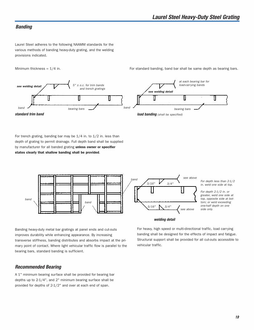
Banding
Minimum thickness = 1/4 in. For standard banding, band bar shall be same depth as bearing bars.
5" ± o.c. for trim bandsand trench gratings
see welding detail
band bearing bars band bearing bars
see welding detail
at each bearing bar forload-carrying bands
standard trim band load banding (shall be specified)
bandband
band
For trench grating, banding bar may be 1/4 in. to 1/2 in. less than
depth of grating to permit drainage. Full depth band shall be supplied
by manufacturer for all banded grating unless owner or specifier
states clearly that shallow banding shall be provided.
see above
3/16" 3/4"
3/16" 3/4"see above
For depth less than 2-1/2in. weld one side at top.
For depth 2-1/2 in. orgreater, weld one side attop, opposite side at bot-tom; or weld exceedingone-half depth on oneside only.
welding detail
Banding heavy-duty metal bar gratings at panel ends and cut-outs
improves durability while enhancing appearance. By increasing
transverse stiffness, banding distributes and absorbs impact at the pri-
mary point of contact. Where light vehicular traffic flow is parallel to the
bearing bars, standard banding is sufficient.
11119999
Laurel Steel adheres to the following NAAMM standards for the
various methods of banding heavy-duty grating, and the welding
provisions indicated.
Laurel Steel Heavy-Duty Steel Grating
For heavy, high speed or multi-directional traffic, load carrying
banding shall be designed for the effects of impact and fatigue.
Structural support shall be provided for all cut-outs accessible to
vehicular traffic.
Recommended BearingA 1" minimum bearing surface shall be provided for bearing bar
depths up to 2-1/4", and 2" minimum bearing surface shall be
provided for depths of 2-1/2" and over at each end of span.
In order to obtain a quotation or place an order for Laurel
Steel HD grating, it is necessary to provide information for
each of the categories listed below. Please refer to pages 4
and 5 for explanation.
Bearing bar: Size, material, spacing, surface
Cross bar: Either 2" or 4" spacing. Please specify standard,
round, or rectangular; specify surface if rectangular.
Finish: Common grating finishes are mill finish (as
fabricated), shop-applied black paint, and hot dip
galvanized coating. Please contact Laurel Steel to
request any special coating requirements.
Area: to be covered with grating
Span: direction of bearing bars
Banding Requirements
Call or fax your inquiry to our sales department, or you can submit an
inquiry by contacting our Website, [email protected]. The sketch
shown here also appears on our Website, with drop-down menus to
make it easy to submit an inquiry or order.
Grating shall be Laurel Steel Heavy-Duty Type 22W4, with 3 x 3/8"
bearing bars spaced 1-3/8" c/c, and 1/2" diameter cross bar
spaced 4" c/c. All material shall be ASTM A-36. All bearing
bar/cross bar intersections shall be plug-welded. The ends of all
grating panels shall be trim banded.
Sufficient grating shall be supplied to cover an area 36'-0" wide x
3’-8" span. The Laurel Steel Heavy-Duty Grating can support the
AASHTO H-20 design truck on the specified span. Grating shall
be hot-dipped galvanized after fabrication, in accordance with
ASTM A-123.
Grating shall be supplied in conformance with Standard
Specifications and Code of Practice as provided for in National
Association of Architectural Metal Manufacturers (NAAMM) Heavy-
Duty Metal Bar Grating Manual MMBG 532-00.
22220000
WIDTH
BEARING BAR SPACING
CL
CL
CROSS BAR SPACING
CL
CL
SPAN
SERRATED RECTANGULAR CROSS BAR
SERRATED BEARING BAR
SMOOTH BEARING BAR
SPECIFY BEARING BAR HEIGHT & THICKNESS
SPECIFY HEIGHT & THICKNESS OF RECTANGULAR CROSS BAR
SMOOTH RECTANGULAR CROSS BAR
SPECIFY Ø OF ROUND CROSS BAR
BAND BAR (OPTIONAL)
Ordering A Laurel Steel Heavy-Duty Steel Grating
Sample Specification:
22221111
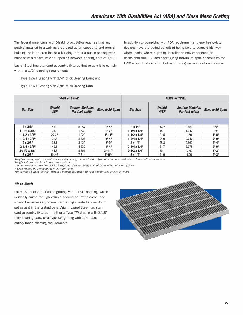
The federal Americans with Disability Act (ADA) requires that any
grating installed in a walking area used as an egress to and from a
building, or in an area inside a building that is a public passageway,
must have a maximum clear opening between bearing bars of 1/2".
Laurel Steel has standard assembly fixtures that enable it to comply
with this 1/2" opening requirement:
Type 12W4 Grating with 1/4" thick Bearing Bars; and
Type 14W4 Grating with 3/8" thick Bearing Bars
In addition to complying with ADA requirements, these heavy-duty
designs have the added benefit of being able to support highway
wheel loads, where a grating installation may experience an
occasional truck. A load chart giving maximum span capabilities for
H-20 wheel loads is given below, showing examples of each design:
Weights are approximate and can vary depending on panel width, type of cross bar, and mill and fabrication tolerances.Weights shown are for 4" cross bar centers.Section Modulus based on 13.71 bars/foot of width (14W) and 16.0 bars/foot of width (12W).*Span limited by deflection (L/400 maximum).For serrated grating design, increase bearing bar depth to next deeper size shown in chart.
Bar Size Weight#SF
Section ModulusPer foot width Max. H-20 Span Bar Size Weight
#/SFSection Modulus
Per foot width Max. H-20 Span
Americans With Disabilities Act (ADA) and Close Mesh Grating
14W4 or 14W2 12W4 or 12W2
1 x 3/8" 18.6 0.857 1'-4" 1 x 14" 14.7 0.667 1'2"1 -1/4 x 3/8" 23.0 1.339 1'-7" 1-1/4 x 1/4" 18.1 1.042 1'5"1-1/2 x 3/8" 27.35 1.929 1'-11" 1-1/2 x 1/4" 21.5 1.50 1'-8"1-3/4 x 3/8" 31.7 2.625 2'-4" 1-3/4 x 1/4" 24.9 2.042 2'-0"
2 x 3/8" 36.1 3.429 2'-9" 2 x 1/4" 28.3 2.667 2'-4"2-1/4 x 3/8" 40.5 4.339 3'-4" 2-1/4 x 1/4" 31.7 3.375 2'-9"2-/1/2 x 3/8" 44.8 5.357 3'-11"* 2-1/2 x 1/4" 35.1 4.167 3'-2"
3 x 3/8" 54.46 7.714 5'-0"* 3 x 1/4" 41.9 6.00 4'-3"
Close Mesh
Laurel Steel also fabricates grating with a 1/4" opening, which
is ideally suited for high volume pedestrian traffic areas, and
where it is necessary to ensure that high heeled shoes don't
get caught in the grating bars. Again, Laurel Steel has stan-
dard assembly fixtures — either a Type 7W grating with 3/16"
thick bearing bars, or a Type 8W grating with 1/4" bars — to
satisfy these exacting requirements.

Laurel Steel welcomes the opportunity to utilize its basic
metalworking equipment, fabrication experience and certified welders
to fabricate one-of-a-kind hopper covers, grizzlies or egg crates that
are specially designed for use in a variety of heavy industries.
22222222
Special Fabrications
Supplementary Bar Grating
Laurel Steel offers a special fabrication that combines heavy
and light bearing bars to produce a product with unique capabilities.
Deep heavy-duty bars provide the strength to support vehicle loads;
these deeper bars are alternated with lighter, shallower bars that
serve to reduce the grating’s clear opening. This is an extremely
economical solution for certain demanding applications. Call for
additional details.
Grizzlies
There are practically no restrictions on what bar sizes can be used
to construct a grating commonly referred to as a grizzly. Grizzlies use
solid bearing bars (no notching); cross bars are essentially spacer
blocks welded at 90 degrees to the bearing bars. These weldments
generally require wide spaces between bars. Hence, extremely heavy
bar sizes (up to 12" x 1", for example) are typically used, and bb/cb
joints are generally welded in all four corners.
Egg Crates
Egg crates are constructed using equal size bearing bars and cross
bars. A notch is punched into the top half of the bearing bar; a simi-
lar notch is punched into the bottom half of the cross bar. When
assembled and welded (generally using a full depth fillet weld in
opposite corner of the bb/cb joint), a grating with equal strength in
both directions is produced. Due to equipment restrictions, not all
bar sizes can be used to construct an egg crate. Please contact
Laurel Steel with specific requirements.
4"
11/16"CL
CL
CL
CL

22223333
The design versatility and short fabrication
response inherent in hand made Laurel Steel
Heavy-Duty Grating is perfectly suited for the
roadway inlet grating market. Heavy and
Highway contractors have come to rely on
Laurel Steel for a wide variety of both grating
and related fabricated steel items.
Laurel utilizes robotic technology to maintain
its competitive edge in inlet grates. Precise,
high capacity presses, automated feed lines
and robotic welding capabilities combine to
provide our customers with consistent, reli-
able quality at the lowest possible price. In
its home state, Pennsylvania, Laurel Steel is
approved to supply all SECTION 605.2(a) and
606.2 fabricated steel roadway items, as
shown in the following list, and has been a
reliable vendor to that industry since 1987.
Laurel Steel typically stocks many of these
items for immediate shipment.
• H-25 Straight Grate 2 x 4
• H-25 Bicycle Safe Grate 2 x 4
• Steel Vane Grates
• Structural Steel Grade Adjustment Ring
• Cast In Place Light Angle ‘M’ Frame
• Precast Light Angle ‘M’ and ‘C’ Frames
• Light Angle DH Frame
• DH Grates
• H-25 Straight Grate 2 x 6
• ‘H’ Grate and Frame
Roadway Inlets and Frames
Advanced robotic welding technology is perfectly suited for standard roadway inlet grates.

22224444
Roadway Inlets and Frames
Structural frames complement inlet grating line.
In addition to Pennsylvania, Laurel Steel also supplies standard
state-approved items to Maryland, Virginia and New York. We
welcome the opportunity to develop partnerships with distributors
and users looking for reliable suppliers. Let us provide pricing
based on your drawing and specifications.
Laurel Steel also supplies products to the precast industry used in
a wide variety of commercial applications. With an array of grating
fixtures available, Laurel Steel can design and supply custom
products for use in precast drainage boxes and troughs. Let our
Sales Department recommend an inlet or trench grating that
enhances the value of the products that you sell.
2 x 2 Frame/Grate: Consistent quality, ready availability makes
Laurel Steel ideal partners with concrete precasters.
Straight/Vane Grates: Contractors rely on
Laurel Steel for a variety of inlet designs.
22225555
Walkway Grating
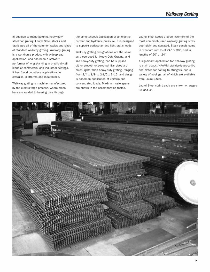
In addition to manufacturing heavy-duty
steel bar grating, Laurel Steel stocks and
fabricates all of the common styles and sizes
of standard walkway grating. Walkway grating
is a workhorse product with widespread
application, and has been a stalwart
performer of long standing in practically all
kinds of commercial and industrial settings.
It has found countless applications in
catwalks, platforms and mezzanines.
Walkway grating is machine manufactured
by the electro-forge process, where cross
bars are welded to bearing bars through
the simultaneous application of an electric
current and hydraulic pressure. It is designed
to support pedestrian and light static loads.
Walkway grating designations are the same
as those used for Heavy-Duty Grating, and
like heavy-duty grating, can be supplied
either smooth or serrated. Bar sizes are
much lighter than heavy-duty grating, ranging
from 3/4 x 1/8 to 2-1/2 x 3/16, and design
is based on application of uniform and
concentrated loads. Maximum safe spans
are shown in the accompanying tables.
Laurel Steel keeps a large inventory of the
most commonly used walkway grating sizes,
both plain and serrated. Stock panels come
in standard widths of 24" or 36", and in
lengths of 20' or 24'.
A significant application for walkway grating
is stair treads; NAAMM standards prescribe
end plates for bolting to stringers, and a
variety of nosings, all of which are available
from Laurel Steel.
Laurel Steel stair treads are shown on pages
34 and 35.

22226666
Walkway Grating
Standard Panel Widths
Weight Chart (in pounds/square foot)
Bearing Bars
3/4 x 1/8 1/4 N/A 3.99 4.63 4.95 5.593/4 x 3/16 1/4 9.28 5.67 6.31 7.11 7.75
1 x 1/8 1/4 8.29 5.15 5.79 6.44 7.081 x 3/16 1/4 12.16 7.35 7.99 9.27 9.91
1-1/4 x 1/8 1/4 10.18 6.2 6.84 7.79 8.431-1/4 x 3/16 1/4 15.04 9.03 9.67 11.43 12.071-1/2 x 1/8 1/4 12.16 7.35 7.99 9.27 9.911-1/2 x 3/16 5/16 18.28 10.94 11.8 13.82 14.681-3/4 x 3/16 5/16 21.16 12.62 13.48 15.98 16.84
2 x 3/16 5/16 24.04 14.3 15.16 18.14 192-1/4 x 3/16 5/16 26.74 15.87 16.74 20.16 21.032-1/2 x 3/16 5/16 29.62 17.55 18.42 22.32 23.19
Number ofBearing Bars 11W4 15W4 and 15W2 19W4 and 19W2
2 7/8 3 1 9/16 4 2 1/45 2 15/16 4 15/16 4 7/8 6 3 5/8 6 1/8 6 1/167 4 5/16 7 5/16 7 1/4 8 5 6 3/4 7 5/6 8 1/2 8 7/169 5 11/16 7 11/16 7 5/8 9 11/16 9 5/8 10 6 3/8 8 5/8 8 9/16 10 7/8 10 13/1611 7 1/16 9 9/16 9 1/2 12 1/16 1212 7 3/4 10 1/2 10 7/16 13 1/4 13 3/1613 8 7/16 11 7/16 11 3/8 14 7/16 14 3/8 14 9 1/8 12 3/8 12 5/16 15 5/8 15 9/1615 9 13/16 13 5/16 13 1/4 16 13/16 16 3/4 16 10 1/2 14 1/4 14 3/16 18 17 15/1617 11 3/16 15 3/16 15 1/8 19 3/16 19 1/8 18 11 7/8 16 1/8 16 1/16 20 3/8 20 5/1619 12 9/16 17 1/16 17 21 9/16 21 1/2 20 13 1/4 18 17 15/16 22 3/4 22 11/1621 13 15/16 18 15/16 18 7/8 23 15/16 23 7/8 22 14 5/8 19 7/8 19 13/16 25 1/8 26 1/1623 15 5/16 20 13/16 20 3/4 26 5/16 26 1/4 24 16 21 3/4 21 11/16 27 1/2 27 7/1625 16 11/16 22 11/16 22 5/8 28 11/16 28 5/8 26 17 3/8 23 5/8 23 9/16 29 7/8 29 13/1627 18 1/16 24 9/16 24 1/2 31 1/16 3128 18 3/4 25 1/2 25 7/16 32 1/4 32 3/1629 19 7/16 26 7/16 26 3/8 33 7/16 33 3/8 30 20 1/8 27 3/8 27 5/16 34 5/8 34 9/1631 20 13/16 28 5/16 28 1/4 35 13/16 35 3/4 32 21 1/2 29 1/4 29 3/1633 22 3/16 30 3/16 30 1/8 34 22 7/8 31 1/8 31 1/1635 23 9/16 32 1/16 3236 24 1/4 33 32 15/1637 33 15/16 33 7/8 38 34 7/8 34 13/1639 35 13/16 35 3/4
Cross Bars Type 11W4 Type 19W4 Type 19W2 Type 15W4 Type 15W2
with 3/16" BB’s 3/16" bars 1/8" bars 3/16" bars 1/8" bars

22227777
Load Table for Steel Walkway Grating Type 19-W
To obtain equivalent load for 15W grating, multiply by 1.27.To obtain equivalent load for 11W grating, multiply by 1.71.
3/4 x 1/8" 42 U 355 227 158 116 89 703.99# Dc 0.099 0.155 0.223 0.304 0.397 0.503
C 355 284 237 203 178 158Dc 0.079 0.124 0.179 0.243 0.318 0.402
3/4 x 3/16 46 U 533 341 237 174 133 1055.67# Du 0.099 0.155 0.223 0.304 0.397 0.503
C 533 426 355 305 266 237Dc 0.079 0.124 0.179 0.243 0.318 0.402
1 x 1/8 51 U 632 404 281 206 158 125 101 84 705.15# Du 0.074 0.116 0.168 0.228 0.298 0.377 0.466 0.563 0.670
C 632 505 421 361 316 281 253 230 211Dc 0.060 0.093 0.134 0.182 0.238 0.302 0.372 0.451 0.536
1 x 3/16 57 U 947 606 421 309 237 187 152 125 1057.35# Du 0.074 0.116 0.168 0.228 0.298 0.377 0.466 0.563 0.670
C 947 758 632 541 474 421 379 344 316Dc 0.060 0.093 0.134 0.182 0.238 0.302 0.372 0.451 0.536
1-1/4 x 1/8 61 U 987 632 439 322 247 195 158 130 110 93 816.20# Du 0.060 0.093 0.134 0.182 0.238 0.302 0.372 0.451 0.536 0.629 0.730
C 987 789 658 564 493 439 395 359 329 304 282Dc 0.048 0.074 0.107 0.146 0.191 0.241 0.298 0.360 0.429 0.504 0.584
1-1/4 x 3/16 67 U 1480 947 658 483 370 292 237 196 164 140 1219.03# Du 0.060 0.093 0.134 0.182 0.238 0.302 0.372 0.451 0.536 0.629 0.730
C 1480 1184 987 846 740 658 592 538 493 455 423Dc 0.048 0.074 0.107 0.146 0.191 0.241 0.298 0.360 0.429 0.504 0.584
1-1/2 x 1/8 70 U 1421 909 632 464 355 281 227 188 158 135 116 101 89 79 707.35# Du 0.050 0.078 0.112 0.152 0.199 0.251 0.310 0.376 0.447 0.524 0.608 0.698 0.794 0.897 1.006
C 1421 1137 947 812 711 632 568 517 474 437 406 379 355 334 316Dc 0.040 0.062 0.089 0.122 0.159 0.201 0.248 0.300 0.358 0.420 0.487 0.559 0.636 0.718 0.804
1-1/2 x 3/16 77 U 2132 1364 947 696 533 421 341 282 237 202 174 152 133 118 10510.94# Du 0.050 0.078 0.112 0.152 0.199 0.251 0.310 0.376 0.447 0.524 0.608 0.698 0.794 0.897 1.006
C 2132 1705 1421 1218 1066 947 853 775 711 656 609 568 533 502 474Dc 0.040 0.062 0.089 0.122 0.159 0.201 0.248 0.300 0.358 0.420 0.487 0.559 0.636 0.718 0.804
1-3/4 x 3/16 87 U 2901 1857 1289 947 725 573 464 384 322 275 237 206 181 161 14312.62# Du 0.043 0.067 0.096 0.130 0.170 0.215 0.266 0.322 0.383 0.450 0.521 0.599 0.681 0.769 0.862
C 2901 2321 1934 1658 1451 1289 1161 1055 967 893 829 774 725 683 645Dc 0.034 0.053 0.077 0.104 0.136 0.172 0.213 0.257 0.306 0.360 0.417 0.479 0.545 0.615 0.689
2 x 3/16 96 U 3789 2425 1684 1237 947 749 606 501 421 359 309 269 237 210 18714.30# Du 0.037 0.058 0.084 0.114 0.149 0.189 0.233 0.282 0.335 0.393 0.456 0.524 0.596 0.673 0.754
C 3789 3032 2526 2165 1895 1684 1516 1378 1263 1166 1083 1011 947 892 842Dc 0.030 0.047 0.067 0.091 0.119 0.151 0.186 0.225 0.268 0.315 0.365 0.419 0.477 0.538 0.603
2-1/4 x 3/16 105 U 4796 3069 2132 1566 1199 947 767 634 533 454 392 341 300 266 23715.87# Du 0.033 0.052 0.074 0.101 0.132 0.168 0.207 0.250 0.298 0.350 0.406 0.466 0.530 0.598 0.67
C 4796 3837 3197 2741 2398 2132 1918 1744 1599 1476 1370 1279 1199 1128 1066Dc 0.026 0.041 0.060 0.081 0.106 0.134 0.166 0.200 0.238 0.280 0.324 0.372 0.424 0.478 0.536
2-1/2 x 3/16 113 U 5921 3789 2632 1933 1480 1170 947 783 658 561 483 421 370 328 29217.55# Du 0.030 0.047 0.067 0.091 0.119 0.151 0.186 0.225 0.268 0.315 0.365 0.419 0.477 0.538 0.603
C 5921 4737 3947 3383 2961 2632 2368 2153 1974 1822 1692 1579 1480 1393 1316Dc 0.024 0.037 0.054 0.073 0.095 0.121 0.149 0.180 0.215 0.252 0.292 0.335 0.381 0.431 0.483
60" 66" 72"
78" 84"
90" 96" 102" 108"
Bearing Bar Size (in.)
Nominal Wt. (lbs.)
Recom. Max. Span (in.) for 1/4"
deflection under 100 lb. Uniform Load
Span in Inches
24" 30" 36" 42" 48" 54"

22228888
Load Table for Welded Stainless Steel Walkway Grating Type 19-W
To obtain equivalent load for 15W grating, multiply by 1.27.To obtain equivalent load for 11W grating, multiply by 1.71.
3/4 x 1/8" 41 U 395 253 175 129 99 783.99# Dc 0.114 0.179 0.257 0.350 0.457 0.579
C 395 316 263 226 197 175Dc 0.091 0.143 0.206 0.280 0.366 0.463
3/4 x 3/16" 46 U 592 379 263 193 148 1175.67# Du 0.114 0.179 0.257 0.350 0.457 0.579
C 592 474 395 338 296 263Dc 0.091 0.143 0.206 0.280 0.366 0.463
1 x 1/8" 51 U 702 449 312 229 175 139 112 93 785.15# Du 0.086 0.134 0.193 0.263 0.343 0.434 0.536 0.648 0.771
C 702 561 468 401 351 312 281 255 234Dc 0.069 0.107 0.154 0.210 0.274 0.347 0.429 0.519 0.617
1 x 3/16" 56 U 1053 674 468 344 263 208 168 139 1177.35# Du 0.086 0.134 0.193 0.263 0.343 0.434 0.536 0.648 0.771
C 1053 842 702 602 526 468 421 383 351Dc 0.069 0.107 0.154 0.210 0.274 0.347 0.429 0.519 0.617
1-1/4 x 1/8" 60 U 1096 702 487 358 274 217 175 145 122 104 906.20# Du 0.069 0.107 0.154 0.210 0.274 0.347 0.429 0.519 0.617 0.724 0.840
C 1096 877 731 627 548 487 439 399 365 337 313Dc 0.055 0.086 0.123 0.168 0.219 0.278 0.343 0.415 0.494 0.579 0.672
1-1/4 x 3/16" 67 U 1645 1053 731 537 411 325 263 217 183 156 1349.03# Du 0.069 0.107 0.154 0.210 0.274 0.347 0.429 0.519 0.617 0.724 0.840
C 1645 1316 1096 940 822 731 658 598 548 506 470Dc 0.055 0.086 0.123 0.168 0.219 0.278 0.343 0.415 0.494 0.579 0.672
1-1/2 x 1/8" 69 U 1579 1011 702 516 395 312 253 209 175 149 129 112 99 87 787.35# Du 0.057 0.089 0.129 0.175 0.229 0.289 0.357 0.432 0.514 0.604 0.700 0.804 0.914 1.032 1.157
C 1579 1263 1053 902 789 702 632 574 526 486 451 421 395 372 351Dc 0.046 0.071 0.103 0.140 0.183 0.231 0.286 0.346 0.411 0.483 0.560 0.643 0.731 0.826 0.926
1-1/2 x 3/16" 77 U 2368 1516 1053 773 592 468 379 313 263 224 193 168 148 131 11710.94# Du 0.057 0.089 0.129 0.175 0.229 0.289 0.357 0.432 0.514 0.604 0.700 0.804 0.914 1.032 1.157
C 2368 1895 1579 1353 1184 1053 947 861 789 729 677 632 592 557 526Dc 0.046 0.071 0.103 0.140 0.183 0.231 0.286 0.346 0.411 0.483 0.560 0.643 0.731 0.826 0.926
1-3/4 x 3/16" 86 U 3224 2063 1433 1053 806 637 516 426 358 305 263 229 201 178 15912.62# Du 0.049 0.077 0.110 0.150 0.196 0.248 0.306 0.370 0.441 0.517 0.600 0.689 0.784 0.885 0.992
C 3224 2579 2149 1842 1612 1433 1289 1172 1075 992 921 860 806 759 716Dc 0.039 0.061 0.088 0.120 0.157 0.198 0.245 0.296 0.353 0.414 0.480 0.551 0.627 0.708 0.793
2 x 3/16" 95 U 4211 2695 1871 1375 1053 832 674 557 468 399 344 299 263 233 20814.30# Du 0.043 0.067 0.096 0.131 0.171 0.217 0.268 0.324 0.386 0.453 0.525 0.603 0.686 0.774 0.868
C 4211 3368 2807 2406 2105 1871 1684 1531 1404 1296 1203 1123 1053 991 936Dc 0.034 0.054 0.077 0.105 0.137 0.174 0.214 0.259 0.309 0.362 0.420 0.482 0.549 0.619 0.694
2-1/4 x 3/16" 104 U 5329 3411 2368 1740 1332 1053 853 705 592 505 435 379 333 295 26315.87# Du 0.038 0.060 0.086 0.117 0.152 0.193 0.238 0.288 0.343 0.402 0.467 0.536 0.610 0.688 0.771
C 5329 4263 3553 3045 2664 2368 2132 1938 1776 1640 1523 1421 1332 1254 1184Dc 0.030 0.048 0.069 0.093 0.122 0.154 0.190 0.230 0.274 0.322 0.373 0.429 0.488 0.550 0.617
2-1/2 x 3/16" 112 U 6579 4211 2924 2148 1645 1300 1053 870 731 623 537 468 411 364 32517.55# Du 0.034 0.054 0.077 0.105 0.137 0.174 0.214 0.259 0.309 0.362 0.420 0.482 0.549 0.619 0.694
C 6579 5263 4386 3759 3289 2924 2632 2392 2193 2024 1880 1754 1645 1548 1462Dc 0.027 0.043 0.062 0.084 0.110 0.139 0.171 0.207 0.247 0.290 0.336 0.386 0.439 0.495 0.555
60" 66" 72"
78" 84"
90" 96" 102" 108"
Bearing Bar Size (in.)
Nominal Wt. (lbs.)
Recom. Max. Span (in.) for 1/4"
deflection under 100 lb. Uniform Load
Span in Inches
24" 30" 36" 42" 48" 54"

To obtain equivalent load for 15W grating, multiply by 1.27.To obtain equivalent load for 11W grating, multiply by 1.71.
22229999
Load Tables for Aluminum Walkway Grating 19-P
Bearing Bar Size (in.)
Nominal Wt. (lbs.)
Recom. Max. Span (in.) for 1/4"
deflection under 100 lb. Uniform Load
Span in Inches
24" 30" 36" 42" 48" 54"1 x 1/8" 39 U 421 269 187 137 105 83
2# Dc 0.144 0.225 0.324 0.441 0.576 0.729C 421 337 281 241 211 187Dc 0.115 0.180 0.259 0.353 0.461 0.583
1 x 3/16" 44 U 632 404 281 206 158 125or 1" I-bar Du 0.144 0.225 0.324 0.441 0.576 0.729
3# C 632 505 421 361 316 281Dc 0.115 0.180 0.259 0.353 0.461 0.583
1 x 1/4" 47 U 842 539 374 275 211 166 135 111 944# Du 0.144 0.225 0.324 0.441 0.576 0.729 0.900 1.089 1.296
C 842 674 561 481 421 374 337 306 281Dc 0.115 0.180 0.259 0.353 0.461 0.583 0.720 0.871 1.037
1-1/4 x 1/8" 47 U 658 421 292 215 164 130 105 87 733# Du 0.115 0.180 0.259 0.353 0.461 0.583 0.720 0.871 1.037
C 658 526 439 376 329 292 263 239 219Dc 0.092 0.144 0.207 0.282 0.369 0.467 0.576 0.697 0.829
1-1/4 x 3/16" 52 U 987 632 439 322 247 195 158 130 110 93 81or 1-1/4" I-bar Du 0.115 0.180 0.259 0.353 0.461 0.583 0.720 0.871 1.037 1.217 1.411
4# C 987 789 658 564 493 439 395 359 329 304 282Dc 0.092 0.144 0.207 0.282 0.369 0.467 0.576 0.697 0.829 0.973 1.129
1-1/4 x 1/4" 55 U 1316 842 585 430 329 260 211 174 146 125 1075# Du 0.115 0.180 0.259 0.353 0.461 0.583 0.720 0.871 1.037 1.217 1.411
C 1316 1053 877 752 658 585 526 478 439 405 376Dc 0.092 0.144 0.207 0.282 0.369 0.467 0.576 0.697 0.829 0.973 1.129
1-1/2 x 1/8" 53 U 947 606 421 309 237 187 152 125 105 90 77 67 59 52 473# Du 0.096 0.150 0.216 0.294 0.384 0.486 0.600 0.726 0.864 1.104 1.176 1.350 1.536 1.734 1.944
C 947 758 632 541 474 421 379 344 316 291 271 253 237 223 211Dc 0.077 0.120 0.173 0.235 0.307 0.389 0.480 0.581 0.691 0.811 0.941 1.080 1.229 1.387 1.555
1-1/2 x 3/16" 59 U 1421 909 632 464 355 281 227 188 158 135 116 101 89 79 70or 1-1/2 I-bar Du 0.096 0.150 0.216 0.294 0.384 0.486 0.600 0.726 0.864 1.014 1.176 1.350 1.536 1.734 1.944
4# C 1421 1137 947 812 711 632 568 517 474 437 406 379 355 334 316Dc 0.077 0.120 0.173 0.235 0.307 0.389 0.480 0.581 0.691 0.811 0.941 1.080 1.229 1.387 1.555
1-1/2 x 1/4" 64 U 1895 1213 842 619 474 374 303 251 211 179 155 135 118 105 945# Du 0.096 0.150 0.216 0.294 0.384 0.486 0.600 0.726 0.864 1.014 1.176 1.350 1.536 1.734 1.944
C 1895 1516 1263 1083 947 842 758 689 632 583 541 505 474 446 421Dc 0.077 0.120 0.173 0.235 0.307 0.389 0.480 0.581 0.691 0.811 0.941 1.080 1.229 1.387 1.555
1-3/4 x 3/16" 66 U 1934 1238 860 632 484 382 309 256 215 183 158 138 121 107 96or 1-3/4" I-bar Du 0.082 0.129 0.185 0.252 0.329 0.417 0.514 0.622 0.741 0.869 1.008 1.157 1.317 1.486 1.666
5# C 1934 1547 1289 1105 967 860 774 703 645 595 553 516 484 455 430Dc 0.066 0.103 0.148 0.202 0.263 0.333 0.411 0.498 0.592 0.695 0.806 0.926 1.053 1.189 1.333
1-3/4 x 1/4" 71 U 2579 1651 1146 842 645 509 413 341 287 244 211 183 161 143 1276# Du 0.082 0.129 0.185 0.252 0.329 0.417 0.514 0.622 0.741 0.869 1.008 1.157 1.317 1.486 1.666
C 2579 2063 1719 1474 1289 1146 1032 938 860 794 737 688 645 607 573Dc 0.066 0.103 0.148 0.202 0.263 0.333 0.411 0.498 0.592 0.695 0.806 0.926 1.053 1.189 1.333
2 x 3/16" 73 U 2526 1617 1123 825 632 499 404 334 281 239 206 180 158 140 125or 2" I-bar Du 0.072 0.113 0.162 0.221 0.288 0.365 0.450 0.545 0.648 0.761 0.882 1.013 1.152 1.301 1.458
5# C 2526 2021 1684 1444 1263 1123 1011 919 842 777 722 674 632 594 561Dc 0.058 0.090 0.130 0.176 0.230 0.292 0.360 0.436 0.518 0.608 0.706 0.810 0.922 1.040 1.166
2 x 1/4" 79 U 3368 2156 1497 1100 842 665 539 445 374 319 275 240 211 186 1667# Du 0.072 0.113 0.162 0.221 0.288 0.365 0.450 0.545 0.648 0.761 0.882 1.013 1.152 1.301 1.458
C 3368 2695 2246 1925 1684 1497 1347 1225 1123 1036 962 898 842 793 749Dc 0.058 0.090 0.130 0.176 0.230 0.292 0.360 0.436 0.518 0.608 0.706 0.810 0.922 1.040 1.166
2-1/4 x 3/16" 80 U 3197 2046 1421 1044 799 632 512 423 355 303 261 227 200 177 158or 2-1/4" I-bar Du 0.064 0.100 0.144 0.196 0.256 0.324 0.400 0.484 0.576 0.676 0.784 0.900 1.024 1.156 1.296
6# C 3197 2558 2132 1827 1599 1421 1279 1163 1066 984 914 853 799 752 711Dc 0.051 0.080 0.115 0.157 0.205 0.259 0.320 0.387 0.461 0.541 0.627 0.720 0.819 0.925 1.037
2-1/4 x 1/4" 86 U 4263 2728 1895 1392 1066 842 682 564 474 404 348 303 266 236 2118# Du 0.064 0.100 0.144 0.196 0.256 0.324 0.400 0.484 0.576 0.676 0.784 0.900 1.024 1.156 1.296
C 4263 3411 2842 2436 2132 1895 1705 1550 1421 1312 1218 1137 1066 1003 947Dc 0.051 0.080 0.115 0.157 0.205 0.259 0.320 0.387 0.461 0.541 0.627 0.720 0.819 0.925 1.037
2-1/2 x 3/16 87 U 3947 2526 1754 1289 987 780 632 522 439 374 322 281 247 219 195or 2-1/2" I-bar Du 0.058 0.090 0.130 0.176 0.230 0.292 0.360 0.436 0.518 0.608 0.706 0.810 0.922 1.040 1.166
7# C 3947 3158 2632 2256 1974 1754 1579 1435 1316 1215 1128 1053 987 929 877Dc 0.046 0.072 0.104 0.141 0.184 0.233 0.288 0.348 0.415 0.487 0.564 0.648 0.737 0.832 0.933
2-1/2 x 1/4" 93 U 5263 3368 2339 1719 1316 1040 842 696 585 498 430 374 329 291 2609# Du 0.058 0.090 0.130 0.176 0.230 0.292 0.360 0.436 0.518 0.608 0.706 0.810 0.922 1.040 1.166
C 5263 4211 3509 3008 2632 2339 2105 1914 1754 1619 1504 1404 1316 1238 1170Dc 0.046 0.072 0.104 0.141 0.184 0.233 0.288 0.348 0.415 0.487 0.564 0.648 0.737 0.832 0.933
60" 66" 72"
78" 84"
90" 96" 102" 108"
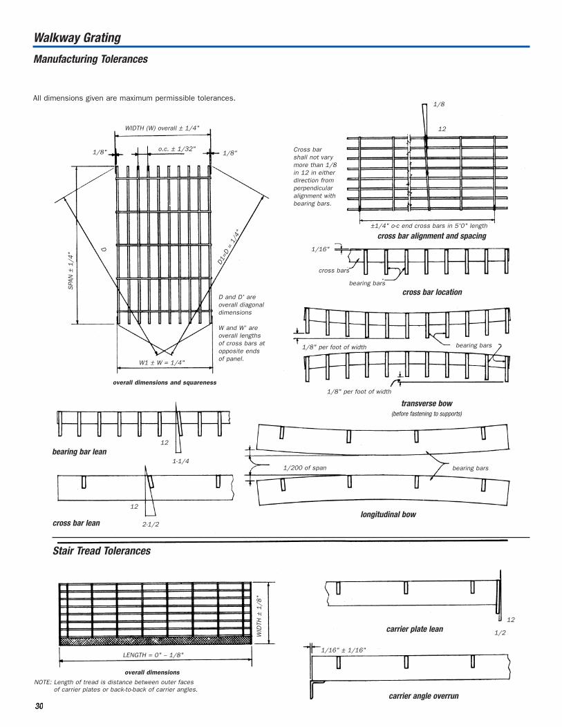
Walkway Grating
All dimensions given are maximum permissible tolerances.
Manufacturing Tolerances
33330000
WIDTH (W) overall ± 1/4"
o.c. ± 1/32"1/8" 1/8"
D1=
D=
1/4"
D
SPA
N±
1/4
"
W1 ± W = 1/4"
D and D' areoverall diagonaldimensions
W and W' areoverall lengthsof cross bars atopposite endsof panel.
Cross barshall not varymore than 1/8in 12 in eitherdirection fromperpendicularalignment withbearing bars.
1/8
12
±1/4" o-c end cross bars in 5'0" length
cross bar alignment and spacing
cross bars
1/16"
bearing bars
cross bar location
1/8" per foot of width bearing bars
1/8" per foot of width
transverse bow(before fastening to supports)
overall dimensions and squareness
12
1-1/4bearing bar lean
12
2-1/2cross bar lean
1/200 of span bearing bars
longitudinal bow
Stair Tread Tolerances
WID
TH±
1/8
"
LENGTH = 0" – 1/8"
overall dimensions
12
1/2carrier plate lean
1/16" ± 1/16"
carrier angle overrun
NOTE: Length of tread is distance between outer facesof carrier plates or back-to-back of carrier angles.

33331111
SPAN
(direction of bearing bars)
panel span panel span
pane
lw
idth
pane
lw
idth
3/8"
1/4" clearancebetween endsof cross bars on rectangulargrating.
1/4" 1/4"
1/4"
1/4"
**
bearingbars
bearingbars
bearingbars
bearingbars
bearingbars
bearingbars
min. clearanceequal to supportangle thickness
bearingbars
bearingbars
1/2"
specifiedcutout – 4" x 6"
actualcutout – 5 3/4" x 6"
bearing bar spacing-1 3/16"
*This dimension varies due to bearing barspacing but will not exceed bearing bar spacing.
Walkway Grating
Standard Installation Clearances
Clearances shown are recommended, but vary in accordance with
dimensional tolerances shown on page 30.
Cutouts for circular obstructions are recommended to be at
least 2 in. larger in diameter than the obstruction. It is further
recommended that cutouts for all piping 4 in. or less in diameter
be made in the field.
As shown in the drawing at left, all rectangular cutouts are made to
the next bearing bar beyond the penetration with a clearance not
to exceed bearing bar spacing.
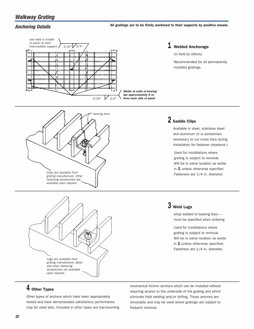
Walkway GratingAll gratings are to be firmly anchored to their supports by positive means.
4 Other Types
Other types of anchors which have been appropriately
tested and have demonstrated satisfactory performance
may be used also. Included in other types are top-mounting
mechanical friction anchors which can be installed without
requiring access to the underside of the grating and which
eliminate field welding and/or drilling. These anchors are
removable and may be used where gratings are subject to
frequent removal.
Anchoring Details
one weld in middleof panel at eachintermediate support 3/16" 3/4"
3/16" 3/4"
Welds at ends of bearingbar approximately 6 in.from each side of panel
1 Welded Anchorage
(in field by others)
Recommended for all permanently
installed gratings.
bearing bars
Clips are available from grating manufacturer. Otherfastening accessories areavailable upon request
2 Saddle Clips
Available in steel, stainless steel
and aluminum (it is sometimes
necessary to cut cross bars during
installation for fastener clearance.)
Used for installations where
grating is subject to removal.
Will be in same location as welds
in 1 unless otherwise specified.
Fasteners are 1/4 in. diameter.
Lugs are available from grating manufacturer. Boltsand other fastening accessories are availableupon request.
3 Weld Lugs
shop welded to bearing bars —
must be specified when ordering
Used for installations where
grating is subject to removal.
Will be in same location as welds
in 1 unless otherwise specified.
Fasteners are 1/4 in. diameter.
33332222

Walkway Grating
Welding Standards
The welding standards shown here apply to those gratings and treads
having a clear opening of not less than 5/8 in. between bearing bars
and those galvanized as per Specifications, page 23. See NAAMM
STANDARD MBG 533 “Welding Specifications for Fabrication of Steel,
Aluminum and Stainless Steel Bar Grating” for welding specifications
and certification of welders.
Toe Platesdepth of toe plate to be in multiples of 1/2in. with a maximum of a + d and a minimumof 4 in. recommended for “a” dimension.
toe plate
a 1/8" 1-12
bearing bars
t = bearing bar thickness
d
at each bearing bar forload-carrying toe plates
t3/4"
toeplate
5" = o.c. for toe plate
1/8" 3/4"
d = bearing bar depth
5" = o.c. for trim bandsand trench gratings
1/8" 3/4"
bandbearing bars band
t d 1/4"
at each bearing bar forload-carrying band
bearing bars
load banding(must be specified)
1/8"
1/8"
1/8"
5"
carrierplate
1/8" 1" at mid-span*
1/8"
1/8"
1/8"
carrierangle
1/8" 1" at mid-span*
When carrier plates are used, the bearing bars in the front
five inches plus the nosing shall be welded to the carrier
plate as shown.
On treads over 9-3/4 in. wide, weld end of center bar also.
*Treads spanning 4 ft. or more shall have two welds, located at the third points.
bearing bars
Banding
standard trim band
Stair Treads
33333333

33334444
Walkway Grating
Laurel Steel Stair Treads
Checker Plate Nosing (Steel)
Cast Aluminum Abrasive Nosing
Laurel Steel stair treads fabricated from electro-forged steel walkway grating can be supplied with either steel checkered plate nosing,
or a cast aluminum abrasive nosing. If steel treads are to be galvanized, the aluminum nosing is bolted to the tread after hot dip galvanizing.
All aluminum treads receive a corrugated nosing.
The dimensions and details shown on the following pages apply to all Laurel Steel treads.
Corrugated Nosing (Aluminum only)
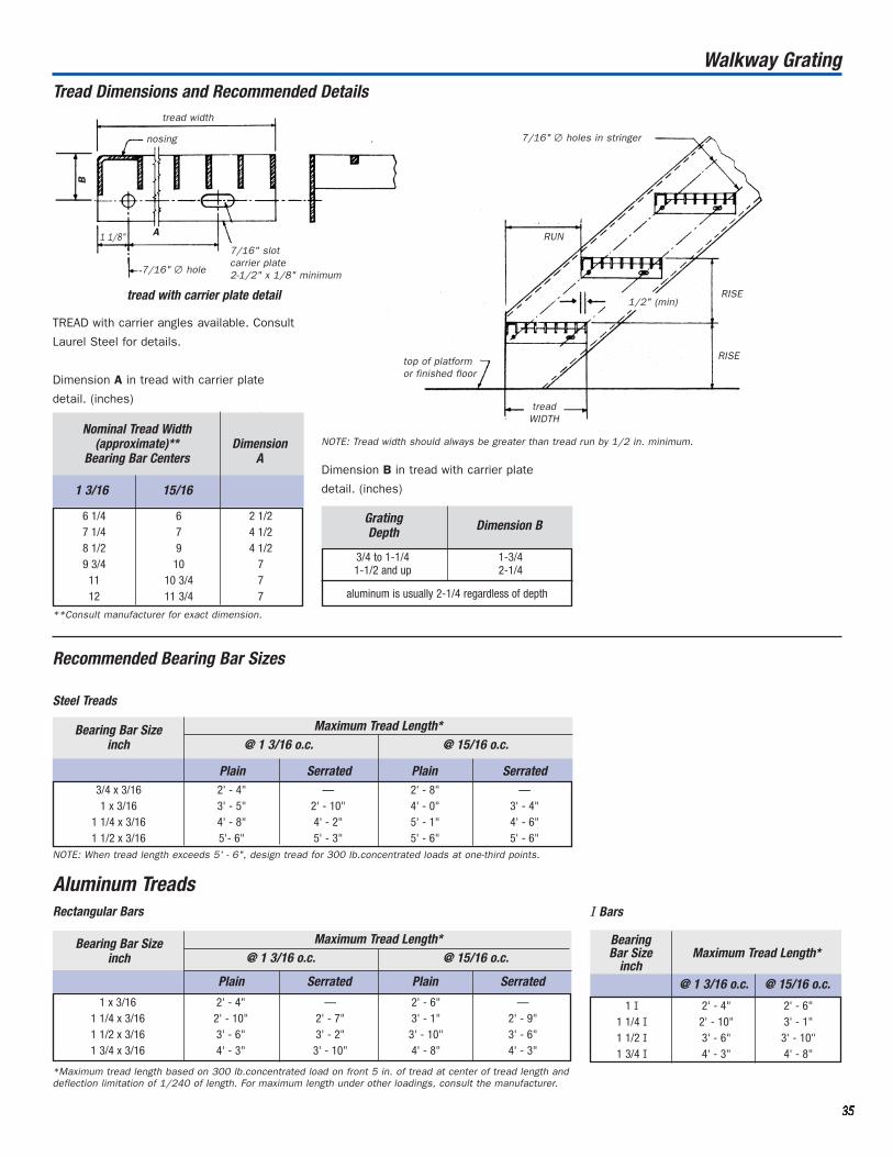
33335555
Tread Dimensions and Recommended Detailstread width
B
nosing
A1 1/8"
7/16" ∅ hole
7/16" slotcarrier plate2-1/2" x 1/8" minimum
tread with carrier plate detail
TREAD with carrier angles available. Consult
Laurel Steel for details.
7/16" ∅ holes in stringer
RUN
1/2" (min)RISE
RISEtop of platformor finished floor
tread
NOTE: Tread width should always be greater than tread run by 1/2 in. minimum.Nominal Tread Width
(approximate)** DimensionBearing Bar Centers A
Grating Depth Dimension B
6 1/4 6 2 1/27 1/4 7 4 1/28 1/2 9 4 1/29 3/4 10 7
11 10 3/4 712 11 3/4 7
Dimension A in tread with carrier plate
detail. (inches)
**Consult manufacturer for exact dimension.
Dimension B in tread with carrier plate
detail. (inches)
Recommended Bearing Bar Sizes
Steel Treads
Bearing Bar Sizeinch
3/4 x 3/16 2' - 4" — 2' - 8" —1 x 3/16 3' - 5" 2' - 10" 4' - 0" 3' - 4"
1 1/4 x 3/16 4' - 8" 4' - 2" 5' - 1" 4' - 6"1 1/2 x 3/16 5'- 6" 5' - 3" 5' - 6" 5' - 6"
@ 1 3/16 o.c. @ 15/16 o.c.
NOTE: When tread length exceeds 5' - 6", design tread for 300 lb.concentrated loads at one-third points.
*Maximum tread length based on 300 lb.concentrated load on front 5 in. of tread at center of tread length anddeflection limitation of 1/240 of length. For maximum length under other loadings, consult the manufacturer.
Bearing Bar Size
inchMaximum Tread Length*
1 3/16 15/16
@ 1 3/16 o.c. @ 15/16 o.c.Maximum Tread Length*
Walkway Grating
I Bars
1 I 2' - 4" 2' - 6"1 1/4 I 2' - 10" 3' - 1"1 1/2 I 3' - 6" 3' - 10"1 3/4 I 4' - 3" 4' - 8"
Aluminum TreadsRectangular Bars
1 x 3/16 2' - 4" — 2' - 6" —1 1/4 x 3/16 2' - 10" 2' - 7" 3' - 1" 2' - 9"1 1/2 x 3/16 3' - 6" 3' - 2" 3' - 10" 3' - 6"1 3/4 x 3/16 4' - 3" 3' - 10" 4' - 8" 4' - 3"
Maximum Tread Length*
@ 1 3/16 o.c. @ 15/16 o.c.
Plain Serrated Plain Serrated
Plain Serrated Plain Serrated
Bearing Bar Sizeinch
3/4 to 1-1/4 1-3/41-1/2 and up 2-1/4
aluminum is usually 2-1/4 regardless of depth
treadWIDTH

Complementing Laurel Steel’s Heavy-Duty
and Walkway Grating product offerings is
Expanded Metal. Used extensively in
industrial settings to enclose machinery
and protect personnel, it is also an
extremely lightweight option for supporting
certain pedestrian and light machinery
loads. Its familiar diamond-shaped pattern
is also used in situations requiring a
decorative appearance.
Expanded metal is made from a process
that begins with a solid plate, which is then
‘slit’ by a series of dies to create diamond
patterns of varying configurations. The
resulting product is lightweight and easy to
fabricate on-site. Laurel Steel stocks all of
the common patterns and sheet sizes for
immediate delivery. The Design Tables on
pages 37 to 40 describe the available
patterns, sizes, materials and sheet sizes
typically stocked. Call for availability.
terminology
shearing tolerances
STYLE DIMENSION - Nominal dimension ShortWay of Design (SWD)
DESIGN SIZE - Actual dimension SWD andLWD. Measured from a point to a correspondingpoint on the following design.
SWO- Short Way of Opening.
LWO - Long Way of Opening.
STRANDS - The sides of design.
STRAND THICKNESS - Gauge thickness ofmetal expanded.
STRAND WIDTH - Amount of metal fed underdies to produce one strand.
BOND - Where two strands intersect.
Eliminate sprongs or jagged edges.
TOLERANCE - Minus 0 plus 1/2 the designsize, either SWD or LWD.
RANDOM - This type of shearing leaves
prongs or jagged edges.
TOLERANCE ± 1/4"
GRATING: ± 1/4"
Random Sheared
Bonds Bonds Sheared
Expanded Metal
LWOLWD
Long Way of Design
Strand Thickness
SWDShort Wayof Design
Strand Width
SWO
33336666
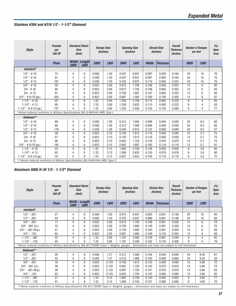
standard*
1/2" - # 18 73 4 8 0.500 1.20 0.437 0.937 0.087 0.050 0.164 24 10 701/2" - # 16 91 4 8 0.500 1.20 0.437 0.937 0.087 0.062 0.164 24 10 701/2" - # 13 187 4 8 0.500 1.20 0.325 0.875 0.119 0.093 0.225 24 10 703/4" - # 18 48 4 8 0.923 2.00 0.812 1.750 0.106 0.050 0.202 13 6 853/4 - # 16 60 4 8 0.923 2.00 0.812 1.750 0.106 0.062 0.202 13 6 833/4 - # 13 91 4 8 0.923 2.00 0.750 1.687 0.107 0.093 0.202 13 6 80
3/4" - # 9 (10 ga.) 205 4 8 0.923 2.00 0.687 1.562 0.160 0.140 0.300 13 6 671-1/2" - # 16 45 4 8 1.33 3.00 1.250 2.750 0.115 0.062 0.222 9 4 851-1/2" - # 13 68 4 8 1.33 3.00 1.250 2.625 0.115 0.093 0.222 9 4 83
1-1/2" - # 9 (10 ga.) 137 4 8 1.33 3.00 1.250 2.500 0.155 0.140 0.280 9 4 77*Above material conforms to Military Specifications MIL-S-46044A (MR) Type I.
flattened**1/2" - # 18 69 4 8 0.500 1.26 0.312 1.000 0.098 0.040 0.040 24 9.5 601/2" - # 16 86 4 8 0.500 1.26 0.312 1.000 0.099 0.050 0.050 24 9.5 601/2" - # 13 178 4 8 0.500 1.26 0.240 0.915 0.132 0.080 0.080 24 9.5 573/4" - # 18 46 4 8 0.923 2.10 0.750 1.812 0.118 0.040 0.040 13 5.7 753/4 - # 16 57 4 8 0.923 2.10 0.750 1.812 0.118 0.050 0.050 13 5.7 753/4 - # 13 86 4 8 0.923 2.10 0.625 1.750 0.120 0.070 0.070 13 5.7 75
3/4" - # 9 (10 ga.) 195 4 8 0.923 2.10 0.562 1.687 0.165 0.119 0.119 13 5.7 611-1/2" - # 16 43 4 8 1.33 3.15 1.062 2.750 0.128 0.050 0.050 9 3.8 801-1/2" - # 13 65 4 8 1.33 3.15 1.000 2.625 0.130 0.079 0.079 9 3.8 80
1-1/2" - # 9 (10 ga.) 131 4 8 1.33 3.15 0.937 2.625 0.165 0.119 0.119 9 3.8 75**Above material conforms to Military Specifications MIL-S-46044A (MR) Type II.
33337777
Expanded Metal
Stainless #304 and #316 1/2 - 1-1/2" Diamond
Number of Designs per footStyle
Pounds per
100 SF
Standard SheetSize (feet)
Design Size(Inches)
Opening Size(Inches)
Strand Size (Inches)
OverallThickness(Inches)
(%)Open Area
Plain Width Length SWD LWD SWO LWO Width Thickness SWD LWDSWD LWD
Aluminum 5005 H-34 1/2 - 1-1/2" Diamond
Number of Designs per footStyle
Pounds per
100 SF
Standard SheetSize (feet)
Design Size(Inches)
Opening Size(Inches)
Strand Size (Inches)
OverallThickness(Inches)
(%)Open Area
Plain Width Length SWD LWD SWO LWO Width Thickness SWD LWDSWD LWDstandard*
1/2" - .051 27 4 8 0.500 1.20 0.375 0.937 0.093 0.051 0.158 24 10 651/2" - .081 44 4 8 0.500 1.20 0.375 0.937 0.096 0.081 0.186 24 10 603/4" - .051 17 4 8 0.923 2.00 0.812 1.750 0.109 0.051 0.200 13 6 78
3/4" - 081 (Lt.) 32 4 8 0.923 2.00 0.750 1.680 0.129 0.081 0.220 13 6 763/4" - .081 (Hvy.) 41 4 8 0.923 2.00 0.750 1.680 0.165 0.081 0.300 13 6 69
3/4" - .125 65 4 8 0.923 2.00 0.687 1.680 0.169 0.125 0.305 13 6 681-1/2" - .081 22 4 8 1.33 3.00 1.187 2.500 0.128 0.081 0.240 9 4 851-1/2" - .125 43 4 8 1.33 3.00 1.187 2.500 0.162 0.125 0.300 9 4 79
*Above material conforms to Military Specifications MIL-M-17999B Class I. Weights, gauges , dimensions and sizes are subject to mill tolerances.
flattened**1/2" - .051 26 4 8 0.500 1.27 0.312 1.000 0.104 0.040 0.040 24 9.50 611/2" - .081 42 4 8 0.500 1.27 0.312 1.000 0.105 0.060 0.060 24 9.50 583/4" - .051 16 4 8 0.923 2.125 0.750 1.812 0.122 0.040 0.040 13 5.66 72
3/4" - 081 (Lt.) 30 4 8 0.923 2.125 0.687 1.750 0.143 0.070 0.070 13 5.66 703/4" - .081 (Hvy.) 39 4 8 0.923 2.125 0.687 1.750 0.181 0.070 0.070 13 5.66 63
3/4" - .125 62 4 8 0.923 2.125 0.625 1.750 0.187 0.095 0.095 13 5.66 621-1/2" - .081 21 4 8 1.33 3.15 1.062 2.750 0.143 0.055 0.055 9 3.80 771-1/2" - .125 41 4 8 1.33 3.15 1.000 2.750 0.181 0.080 0.080 9 3.80 70
**Above material conforms to Military Specifications MIL-M-17999B Class II. Weights, gauges , dimensions and sizes are subject to mill tolerances.

Expanded Metal
Carbon Steel
Standard
Number of Designs per footStyle
Pounds per
100 SF
Standard SheetSize (feet)
Design Size(Inches)
Opening Size(Inches)
Strand Size (Inches)
OverallThickness(Inches)
(%)Open Area
1/4" - # 20 86 4 8 0.250 1.00 0.125 0.718 0.072 0.036 0.135 48 12 451/4" - # 18 114 4 8 0.250 1.00 0.110 0.718 0.072 0.048 0.147 48 12 431/2" - # 20 43 4 8 0.500 1.20 0.438 0.938 0.072 0.036 0.140 24 10 801/2" - # 18 70 88 4 & 6 8 & 10 0.500 1.20 0.438 0.938 0.088 0.048 0.172 24 10 721/2" - # 16 86 104 4 & 6 8 & 10 0.500 1.20 0.375 0.938 0.087 0.060 0.175 24 10 651/2" - # 13 147 174 4 & 6 8 & 10 0.500 1.20 0.312 0.938 0.096 0.092 0.204 24 10 573/4" - # 16 54 61 4 & 6 8 & 10 0.923 2.00 0.813 1.750 0.101 0.060 0.210 13 6 783/4" - # 13 80 94 4 & 6 8 & 10 0.923 2.00 0.750 1.688 0.096 0.092 0.205 13 6 76
3/4" - # 10 (13 ga.) 120 134 4 & 6 8 & 10 0.923 2.00 0.750 1.625 0.144 0.092 0.290 13 6 723/4" - # 9 (10 ga.) 180 198 4 & 6 8 & 10 0.923 2.00 0.688 1.562 0.150 0.134 0.312 13 6 68
1" - # 16 44 51 4 8 1.00 2.40 0.938 2.062 0.087 0.060 0.192 12 5 821-1/2" - # 18 20 4 8 1.33 3.00 1.313 2.625 0.068 0.048 0.140 9 4 901-1/2" - # 16 40 48 4 8 1.33 3.00 1.250 2.625 0.108 0.060 0.230 9 4 851-1/2" - # 13 60 68 4 & 6 8 & 10 1.33 3.00 1.188 2.500 0.105 0.092 0.242 9 4 85
1-1/2" - # 10 (13 ga.) 79 90 4 & 6 8 & 10 1.33 3.00 1.188 2.500 0.138 0.092 0.284 9 4 801-1/2" - # 9 (10 ga.) 120 144 4 & 6 8 & 10 1.33 3.00 1.125 2.375 0.144 0.134 0.312 9 4 761-1/2" - # 6 (6 ga.) 250 275 4 & 6 8 & 10 1.33 3.00 1.110 2.313 0.203 0.198 0.433 9 4 692" - # 10 (13 ga.) 68 81 4 8 1.85 4.00 1.625 3.438 0.164 0.092 0.327 6.5 3 822" - # 9 (10 ga.) 90 99 4 8 1.85 4.00 1.563 3.375 0.149 0.134 0.312 6.5 3 84
1/4" #18 Std. Mesh 1 1/2" #9 Std. Mesh
1/2 # 16 Std. Mesh 3/4" #13 Std. Mesh
33338888
Above material conforms to Military Specification MIL-M-17194C Type I Class I
Plain Galv. Width Length SWD LWD SWO LWO Width Thickness SWD LWDSWD LWD

33339999
1/4" - #20 82 4 & 6 8 0.250 1.05 0.084 0.715 0.079 0.030 0.030 48 11.600 351/4" - #18 108 4 & 6 8 0.250 1.05 0.075 0.715 0.080 0.040 0.040 48 11.600 351/2" - #20 40 51 4 & 6 8 0.500 1.25 0.375 1.000 0.079 0.029 0.029 24 9.500 651/2" - #18 66 83 4 & 6 8 & 10 0.500 1.25 0.312 1.000 0.097 0.039 0.039 24 9.500 601/2" - #16 82 98 4 & 6 8 & 10 0.500 1.25 0.312 1.000 0.096 0.050 0.050 24 9.500 631/2" - #13 140 161 4 & 6 8 & 10 0.500 1.25 0.265 1.000 0.107 0.070 0.070 24 9.500 523/4" - #16 51 57 4 & 6 8 & 10 0.923 2.10 0.750 1.750 0.111 0.048 0.048 13 5.700 743/4" - #14 63 74 4 & 6 8 & 10 0.923 2.10 0.688 1.813 0.105 0.061 0.061 13 5.700 743/4 - #13 75 88 4 & 6 8, 10 & 12 0.923 2.10 0.688 1.781 0.106 0.070 0.070 13 5.700 74
3/4" - #10 (13 ga.) 114 128 4 8 0.923 2.10 0.637 1.755 0.160 0.070 0.070 13 5.700 683/4" - #9 (10 ga.) 171 188 4 & 6 8, 10 & 12 0.923 2.10 0.563 1.688 0.165 0.120 0.120 13 5.700 63
1" - #16 41 50 4 & 6 8 1.000 2.50 0.813 2.250 0.098 0.050 0.050 12 4.684 781-1/2" - #16 38 46 4 & 6 8 1.330 3.20 1.062 2.750 0.119 0.048 0.048 9 3.750 831-1/2" - #14 46 54 4 & 6 8 1.330 3.20 1.062 2.750 0.134 0.060 0.060 9 3.750 801-1/2" - #13 57 66 4 & 6 8 & 10 1.330 3.20 1.062 2.750 0.116 0.070 0.070 9 3.750 80
1-1/2" - #9 (10 ga.) 114 125 4 & 6 8, 10 & 12 1.330 3.20 1.000 2.563 0.158 0.110 0.110 9 3.750 75
1/4" #18 Flat Mesh 3/4" #13 Flat Mesh
1/2" #16 Flat Mesh 1-1/2" #9 Flat Mesh
Expanded Metal
Flattened
Carbon Steel
Number of Designs per footStyle
Pounds per
100 SF
Standard Sheet Size (feet)
Design Size(Inches)
Opening Size(Inches)
Strand Size (Inches)
OverallThickness(Inches)
(%)Open Area
Above material conforms to Military Specification MIL-M-17194C Type II Class I
Plain Galv. Width Length SWD LWD SWO LWO Width Thickness SWD LWDSWD LWD

44440000
Expanded Grating Data
Carbon Steel Expanded Grating
Carbon Steel Flattened Grating
SizePounds per
SF
Standard Sheet Size (feet)
Width LengthDesign Size
(Inches)
LWD
Opening Size(Inches)
LWO
Width
Thickness
OverallThickness(Inches)
LWDSWD
(%)Open Area
Above material meets all requirements of Military Specifications MIL-M 17194C (Metals, Expanded, Steel) and MIL-G 18015 (Ships) Gratings, Metals, other than BarType) and the deflection requirements of Federal Specification RR-G-661-B.
SWOSWDLWDSWD
SizePounds per
SF
Standard Sheet Size (feet)
Width LengthDesign Size
(Inches)
LWD
Opening Size(Inches)
LWO
Width
Thickness
OverallThickness(Inches)
LWDSWD
(%)Open Area
2.8 lbs. 2.8 — 4 8 1.33 5.67 .81 4.00 .285 .16 .160 9 2.25 552.95 lbs. 2.95 — 4 8 2.00 6.38 1.31 5.50 .340 .220 .220 6 2 643.75 lbs. 3.75 — 4 8 1.33 5.67 .81 4.00 .320 .190 .190 9 2.25 504.02 lbs. 4.02 — 4 8 1.41 4.25 .75 3.50 .315 .210 .210 8.5 3 53
SWOSWDLWDSWD
3.0 lbs. 3 3.15 4 & 6 8, 10 & 12 1.33 5.33 0.940 3.440 0.264 0.183 9.540 9 2.25 603.14 lbs. 3.14 3.30 4, 5, & 6 8 & 10 2.00 6.00 1.625 4.880 0.312 0.250 6.656 6 2.00 694.0 lbs. 4 4.18 4, 5, & 6 8 & 10 1.33 5.33 0.940 3.440 0.300 0.215 9.618 9 2.25 554.27 lbs. 4.27 4.46 4 & 6 8 & 10 1.41 4.00 1.000 2.880 0.300 0.250 8.625 8.5 3.00 585.0 lbs. 5 5.20 4, 5, & 6 8 & 10 1.33 5.33 0.813 3.380 0.331 0.250 9.655 9 2.25 506.25 lbs. 6.25 6.47 4 & 6 8 & 12 1.41 5.33 0.813 3.380 0.350 0.312 8.715 8.5 2.25 507.0 lbs. 7 7.25 4 8 1.41 5.33 0.813 3.380 0.391 0.312 8.740 8.5 2.25 45
Plain Galv. Wt.
Plain Galv. Wt.
Grating Selection Chart (Carbon Steel)Carbon Steel Catwalk Grating
Expanded metal grating produced in 10'
sections the short way diamond, by 24",
30" and 36" long way of diamond. The
advantages of catwalk grating are:
reduced installation costs, ease of
fabrication and field handling, unit
economy and maintenance costs.
3 60 lbs. 75 lbs. 90 lbs.3.14 63 lbs. 79 lbs. 94 lbs.
4 80 lbs. 100 lbs. 120 lbs.4.27 85 lbs. 107 lbs. 128 lbs.
5 100 lbs. 125 lbs. 150 lbs.
Weights, Gauges, Dimensions and Sizes listed aboveare subject to mill tolerances.
Expanded metal inventory
The concentrated load deflections for the above selection chart donot exceed the 1/4" maximum deflection as stated by FederalSpecification RR-G-661b and the generally accepted recommenda-tion for normal pedestrian comfort.
SW
D
10
'
2', 2'6", or 3'LWD
StyleLbs./Sq. Ft. 10' x 2' 10' x 2'6" 10'3'
50 lbs. 3.0 3.0 3.0 3.0 3.0 4.0 5.0Light or Occasional 3.14 3.14 3.14 3.14 3.14 4.27 6.25Pedestrian Traffic
100 lbs. 3.0 3.0 3.0 4.0 5.0 7.0 7.0Normal or Frequent 3.14 3.14 3.14 4.27 6.25Pedestrian Traffic
150 lbs. 3.0 4.0 4.0 5.0 6.25 7.0Heavy or Constant 3.14 4.27 4.27 6.25Pedestrian Traffic
200 lbs. 3.0 4.0 4.27 6.25 7.0 7.0Pedestrian Traffic 3.14 4.27 5.0with Light Equipment
250 lbs. 4.0 5.0 5.0 7.04.27 6.25
300 lbs. 4.0 5.0 6.25 7.04.27 6.25
350 lbs. 4.0 6.25 7.04.27
Concentrated Load(Lbs. Per Foot ofLength of Catwalk
or Platform)
Clear Span(Distance between supports, measured
from the inside edge of one support to theinside edge of the next support)
23" 30" 35" 42" 47" 54" 60"

44441111
AASHTO: American Association of State Highway
and Transportation Officials
BAND BAR: Bar welded perpendicular to ends of grating bearing bars
or along the line of a cutout, that extends neither above
nor below the bearing bars. Band bars can be used for
cosmetic reasons, to protect ends of bearing bars from
impact or to enhance load distribution properties of grating.
Trim Banding: A condition in which a band bar is welded to
ends of bearing bars of a grating panel at about 5” centers;
used primarily to improve appearance and stability.
Load Banding: A condition in which a band bar is welded to
every bearing bar of a grating panel; load bands transfer
load between bearing bars.
BEARING BAR: Primary load-carrying component of grating; bearing
bars always run in the direction of the grating span.
CLEAR OPENING: The distance between the faces of adjacent bearing
bars of a grating.
CROSS BAR: Grating component oriented perpendicular to bearing
bars that rigidly hold bearing bars at proper spacing.
CUTOUT: An area of grating removed to clear an obstruction, or to
permit pipes, ducts, columns to pass through the grating.
ELECTROFORGED GRATING: Grating in which bearing bars and cross
bars are joined at their intersections by an automated,
resistance weld.
GRATING SPAN: The direction of the grating bearing bars. Often
referred to as grating length.
Effective Clear Span: The distance between points of
grating support, as defined in a variety of support
conditions. (See sketches on page 17)
GRATING WIDTH: The overall dimension of a grating panel measured
perpendicular to the bearing bars.
NAAMM: National Association of Architectural Metal Manufacturers
NOSING: A component applied to front edge of stair tread or to a
grating platform at the top of a stair, for visual safety and
to sustain edge loads.
PLATE LUG: A fastening device (shop welded into grating panels)
that allows grating to be bolted to supports; used when
removable grating is desirable.
SADDLE CLIP: A fastening device (supplied loose) that allows
grating to be bolted to supports; used when removable
grating is desirable.
SERRATED GRATING: Grating that has the top surface of the bearing
bars or cross bars (or both) notched or scalloped to improve
the skid resistance of the grating.
Glossary

44442222
The NAAMM Heavy-Duty Metal Bar Grating Manual (MGB 532-00)
contains a complete Code of Practice. Excerpts from that manual
are reproduced below and represent generally accepted practice in
the metal bar grating industry.
Drawings and Specifications
The buyer shall be expected to furnish to the seller a set of
construction drawings and specifications of current issue showing
the layout of supports and floor openings correctly dimensioned,
together with the sizes and types of grating required.
Limits of Responsibility: In the absence of written notice
to the contrary, the buyer’s construction plans and
specifications shall be assumed by the seller to be correct in all
details, and the seller’s responsibility shall be limited to furnishing
the products in accord with these documents.
Information to be provided: If drawings and specifications are not
available, buyer shall provide the following:
Description of grating, using standard nomenclature
Plain or serrated surface
Area to be covered with grating
Type of anchorage
Span (direction of bearing bars)
Finish
Method of support
Shipping instructions
All critical dimensions
Approval Drawings: If requested by the buyer, seller shall submit
drawings for approval. Buyer shall return drawings marked with his
approval or desired changes. Any additional work not contemplated by
the contract may result in additional negotiations between buyer and
seller to reach agreement on the cost of the changes. After
all necessary changes are made, the drawings shall be re-submitted
to the buyer for final approval. The seller shall not proceed with any
shop work until drawings are finally approved. (Note: All Laurel Steel
drawings are completed using the latest CADD technology; drawings
can be e-mailed to minimize the time needed for the drawing
approval process.)
Quantity Measurements
Quantity measurements for gratings ordered to specific dimensions,
without drawings, shall be based on width times span of each panel,
with no deduction made for cutouts, unless allowances for cutouts
have been negotiated.
Final grating quantities supplied from drawings shall be on the basis
of gross area measured center to center of supports, or back to back
of supporting angles or channels, or overall dimensions of grating,
whichever is larger, with no deductions for clearances. Allowances for
cutouts will be determined as follows:
• Deductions in area for circular cutouts will only be
allowed when the diameter of the cutout exceeds 3’-6”.
The deductions allowance shall be equal to one half
the square of the diameter of the cutout.
• Deductions in the area for cutouts other than circular
shall be allowed only when the cutout area exceeds
nine (9) square feet.
• No deductions shall be allowed for any triangular
segment or corners of grating wasted in skew cuts.
• Measurements of cuts shall be on the basis of a
minimum of one (1) lineal foot per cut per panel. Any
cut in excess of one (1) lineal foot shall be measured
to the next highest lineal foot. Measurement of banding,
toe plates and nosing shall be on the same basis as
that of cuts.
Backcharges
Buyer shall immediately notify seller upon discovery of
unsatisfactory material; seller shall acknowledge complaint and
initiate an investigation. Seller shall be given the opportunity
to inspect product PRIOR TO ANY CORRECTIVE WORK BEING DONE.
Seller is responsible for providing grating in accordance with
approved drawings and specifications. Seller is NOT responsible
for field changes not received and approved by seller prior to
grating fabrication, improper fabrication and/or erection of
supporting members.
If the inspection and investigation confirm errors in seller’s
fabrication, the seller agrees to replace defective material at
no charge to the buyer.
Code of Standard Practice

One Mount Pleasant Road
Scottdale, PA 15683
Toll Free: 1-800-426-1983
Plant Phone: 724-887-7720
Fax: 724-887-9494
e-mail: [email protected]
www.marwas.com


