+ All Categories
Home > Documents > Hedley, Gelliondale, Alberton (HGA) Wind Farm, South ... · HGA WIND FARM PRELIMINARY GEOTECHNICAL...

Hedley, Gelliondale, Alberton (HGA) Wind Farm, South ... · HGA WIND FARM PRELIMINARY GEOTECHNICAL...

Date post: 20-Mar-2020
Category:
Upload: others
View: 13 times
Download: 0 times
Share this document with a friend
39
17 January 2017 PRELIMINARY GEOTECHNICAL INVESTIGATION Hedley, Gelliondale, Alberton (HGA) Wind Farm, South Gippsland, Victoria REPORT Report Number. 1666035-001-R-Rev1 Distribution: Synergy Wind Pty Ltd - 1 copy Golder Associates Pty Ltd - 1 copy Submitted to: Synergy Wind Pty Ltd PO Box 327 Balaclava VIC 3183
Transcript

17 January 2017

PRELIMINARY GEOTECHNICAL INVESTIGATION

Hedley, Gelliondale, Alberton (HGA) Wind Farm, South Gippsland, Victoria

RE

PO

RT

Report Number. 1666035-001-R-Rev1

Distribution:

Synergy Wind Pty Ltd - 1 copy

Golder Associates Pty Ltd - 1 copy

Submitted to:

Synergy Wind Pty Ltd PO Box 327 Balaclava VIC 3183

HGA WIND FARM PRELIMINARY GEOTECHNICAL INVESTIGATION

17 January 2017 Report No. 1666035-001-R-Rev1 i

Table of Contents

1.0 INTRODUCTION ........................................................................................................................................................ 1

2.0 PROPOSED DEVELOPMENT ................................................................................................................................... 1

3.0 AIMS OF THE INVESTIGATION ............................................................................................................................... 1

4.0 PRELIMINARY INVESTIGATION WORKS ............................................................................................................... 2

4.1 Desk Study ................................................................................................................................................... 2

4.1.1 Geological Information ............................................................................................................................ 2

4.1.2 Groundwater Information ........................................................................................................................ 2

4.1.3 Aerial Photography.................................................................................................................................. 2

4.2 Site Walkover Visit ........................................................................................................................................ 3

4.3 Test Pit Investigation .................................................................................................................................... 3

5.0 RESULTS OF PRELIMINARY GEOTECHNICAL INVESTIGATION ........................................................................ 3

5.1 General Conditions within HGA Wind Farm Area ......................................................................................... 3

5.1.1 Site Geology ........................................................................................................................................... 3

5.1.2 Groundwater ........................................................................................................................................... 5

5.2 Site Conditions within each Zone .................................................................................................................. 5

5.2.1 Zone 1 ..................................................................................................................................................... 5

5.2.2 Zone 2 ..................................................................................................................................................... 6

5.2.3 Zone 3 ..................................................................................................................................................... 7

5.2.4 Zone 4 ..................................................................................................................................................... 8

5.2.5 Zone 5 ..................................................................................................................................................... 9

6.0 DISCUSSION AND RECOMMENDATIONS ............................................................................................................ 10

6.1 Wind Turbine Generator Footings ............................................................................................................... 10

6.1.1 Site Subsurface Conditions ................................................................................................................... 10

6.1.2 Footing Options ..................................................................................................................................... 11

6.1.3 Preliminary Footing Design Parameters ................................................................................................ 11

6.1.4 Possible founding conditions by zone ................................................................................................... 12

6.2 Crane Pads ................................................................................................................................................. 13

6.3 Road Design ............................................................................................................................................... 13

6.4 Further Investigations ................................................................................................................................. 14

7.0 IMPORTANT INFORMATION .................................................................................................................................. 14

HGA WIND FARM PRELIMINARY GEOTECHNICAL INVESTIGATION

17 January 2017 Report No. 1666035-001-R-Rev1 ii

TABLES

Table 1: Wind turbine zone ................................................................................................................................................. 4

Table 2: Geology at (or near) surface based on Alberton 1:50,000 scale mapsheet ........................................................... 4

Table 3: Groundwater levels measured in bores ................................................................................................................. 5

Table 4: Indicative Maximum Ultimate Bearing Pressures (Unfactored) ........................................................................... 12

Table 5: Wind turbine zone and possible founding conditions/options .............................................................................. 13

FIGURES

Figure 1: Site location and layout

Figure 2: Test pit location plan

Figure 3: Wind turbine location and regional geology

PHOTOGRAPHS

Photograph 1: Looking in a southerly direction towards T05 and T04 locations from just east of T06 location ................... 6

Photograph 2: Looking in a southerly direction towards T10 and T11 from South Gippsland Highway and Coal Mine Road Intersection ...................................................................................................................................... 7

Photograph 3: Looking in a westerly direction towards T18 and T22 from northern boundary of Gelliondale State Forest and Ti Tree Road .................................................................................................................................... 8

Photograph 4: Looking in a north easterly direction towards WTG T25 from gate off Old Alberton Drive ........................... 9

Photograph 5: Looking in a north direction towards T20, T21 and T23 from private access road ..................................... 10

APPENDICES

APPENDIX A Reports of Test Pits TP1 and TP3 to TP7

Photographs of Test Pits TP1 and TP3 to TP7

Explanation of notes, abbreviations and terms used on borehole and test pit reports

Method of soil description used on borehole and test pit reports

APPENDIX B Important information

HGA WIND FARM PRELIMINARY GEOTECHNICAL INVESTIGATION

17 January 2017 Report No. 1666035-001-R-Rev1 1

1.0 INTRODUCTION

Synergy Wind Pty Ltd (Synergy Wind) has engaged Golder Associates Pty Ltd (Golder) to perform a

preliminary geotechnical investigation for the proposed Hedley, Gelliondale, Alberton (HGA) Wind Farm

(HGA WF) to be located near Gelliondale township in South Gippsland, Victoria. The investigation was

undertaken in general accordance with our proposal (reference: P1666035-001-Rev0) dated

29 September 2016. Authorisation to proceed with the investigation was provided by Synergy Wind in an

email dated 3 October 2016.

We understand the proposed wind farm will be located near Gelliondale in Gippsland. The site is located

about 170 km south east of Melbourne.

This report presents the results and findings of a desktop study of expected subsurface conditions and a site

visit performed, and a preliminary geotechnical investigation performed for the proposed wind farm

development. The report includes discussion on geotechnical considerations for the proposed wind farm

development, and includes discussion and preliminary comment regarding the design and construction of

wind turbine footings at the site.

2.0 PROPOSED DEVELOPMENT

We understand the proposed wind farm will be located about 170 km south east of Melbourne and will

include 34 wind turbine generators which will be located both north and south of the South Gippsland

Highway at various locations within an approximate 8 km radius of Gelliondale township. The location of the

HGA WF development is presented in Figure 1 – Site location and layout.

Based upon the preliminary information provided by Synergy, we understand the HGA WF will be located

across a number of individual properties held by various landowners. At this stage we have not been

provided with details of the proposed turbine structures or the locations of substations and other supporting

infrastructure.

3.0 AIMS OF THE INVESTIGATION

Based on our understanding of the proposed development, the aims of the preliminary geotechnical

investigation are as follows:

Assess the expected subsurface and groundwater conditions to allow characterisation of the expected

subsurface units and hydrogeological conditions at the sites relevant to the proposed wind turbine

developments.

Assess the foundation materials in which the wind turbines footings will be constructed and provide

preliminary information relevant to the design of the footings.

Provide commentary on indicative foundation design parameters.

Provide preliminary comment on suitability of the site materials for hardstand, cable trench and access

road construction.

Provide comment on other likely geotechnical issues which may impact upon the design of the

proposed wind farm.

HGA WIND FARM PRELIMINARY GEOTECHNICAL INVESTIGATION

17 January 2017 Report No. 1666035-001-R-Rev1 2

4.0 PRELIMINARY INVESTIGATION WORKS

4.1 Desk Study

As part of the preliminary geotechnical investigation a desk study has been undertaken to review readily

available information regarding the site. This work included the following:

A search of relevant geological information including geological maps, published information and

previous studies.

A search of the Australian Groundwater Explorer database maintained by the Bureau of Meteorology.

Review of available aerial photography of the site.

4.1.1 Geological Information

Geological information from a number of sources has been assessed, including:

The Department of Economic Development, Jobs, Transport and Resources ‘GeoVic’ online database.

The 1:31,680 scale ‘Alberton West’ geological mapsheet published by the Geological Survey of Victoria.

The 1:50,000 scale ‘Alberton’ geological mapsheet published by the Geological Survey of Victoria.

The 1:250,000 scale ‘Warragul’ geological mapsheet published by the Geological Survey of Victoria.

Birch W.D. (Editor), 2003. ‘Geology of Victoria’. Geological Society of Australia. Special Publication 23.

Geological Society of Australia (Victoria Division).

Geological Survey of Victoria Report No. 57 ‘Explanatory Notes on the Warragul 1:250,000 Geological

Map.

4.1.2 Groundwater Information

A search was conducted within publically available groundwater databases for registered bores in the vicinity

of the site. The information available for individual groundwater bores can include:

The date of bore completion.

The location of the bores in AMG coordinates.

Ground surface level of the bore.

The depth of the bore, depth range of the bore screened interval and depth to water in the bore.

Basic lithological information.

Results of bore pumping tests (test type, pump depth, flow rate, electrical conductivity and test

duration).

4.1.3 Aerial Photography

Using available aerial photography the following has been assessed as part of the preparation of this report:

Evidence of previous slope instability including slip scars, scarps and landslide debris.

Surficial evidence of the underlying geology. This information can be useful in assessing potential

borrow areas.

Evidence of erosion.

HGA WIND FARM PRELIMINARY GEOTECHNICAL INVESTIGATION

17 January 2017 Report No. 1666035-001-R-Rev1 3

4.2 Site Walkover Visit

A senior geological engineer from Golder Associates visited the site of the proposed HGA WF development

on 14 October 2016 to undertake a general assessment of site access, site topography, surface geology

exposures, slope stability and observe evidence of surface and ground water. Visits were made to selected

wind turbine generator sites on the basis of information obtained during the desk study.

4.3 Test Pit Investigation

A total of six test pits (TP1 and TP3 to TP7) were excavated in general areas of proposed wind turbines as

part of the preliminary geotechnical investigation of the site. The locations of test pits are shown on Figure 2

– Test pit location plan. The test pits were excavated on 17 November, 2016.

Test pits were excavated using a backhoe supplied and operated by a specialist contractor to depths ranging

from about 2.5 m to 2.7 m. Upon completion, the test pits were backfilled with the excavated spoil, tamped

using the excavator bucket and wheel rolled at the surface.

A Dynamic Cone Penetrometer (DCP) test was performed at each test pit location to assess the in situ

strength of near surface soil. These tests were performed to depths ranging from about 1.0 m to 1.7 m.

A geotechnical engineer from Golder located the test pits using a hand held GPS unit, described the

materials encountered in the test pits, performed field tests including the DCP tests and photographed the

test pit excavations and test pit spoil.

The subsurface conditions encountered in the test pits are presented in Appendix A as Reports of Test Pits

TP1 and TP3 to TP7. Photographs of the test pit excavations and test pit spoil, and DCP test results, are

included in the reports along with the following information sheets relevant to the interpretation of the reports:

Explanation of notes, abbreviations and terms used on borehole and test pit reports

Method of soil description used on borehole and test pit reports

5.0 RESULTS OF PRELIMINARY GEOTECHNICAL INVESTIGATION

5.1 General Conditions within HGA Wind Farm Area

5.1.1 Site Geology

At a regional scale, the location of the proposed HGA WF lies within the south eastern area of the Gippsland

Basin. At a more local scale, the site is within the Alberton Depression, on the south western fringe of the

Strzelecki Ranges (Southern Uplands of Victoria).

Geological maps indicate the surface geology mostly includes Quaternary age sediments where the wind

turbines are proposed. These sediments include the following:

Stream alluvium deposits;

River and coastal terraces and flood plain deposits;

Swamp and lagoonal deposits;

Dune, beach and estuarine deposits; and

Aeolian sand sheets.

The surface geology of the site, as shown on the Geological Survey of Victoria Alberton 1:50,000 scale

mapsheet, along with the positions of the proposed wind turbines, is presented on Figure 3, Wind turbine

location and regional geology.

HGA WIND FARM PRELIMINARY GEOTECHNICAL INVESTIGATION

17 January 2017 Report No. 1666035-001-R-Rev1 4

For the purpose of the following discussion the wind farm area has been sub-divided into five geographic

zones, as shown on Figure 3. The wind turbine locations falling within each zone are presented in Table 1.

Table 1: Wind turbine zone

Zone Zone location description Wind Turbine Number

1 South of South Gippsland Highway, east of Birds Road T01 to T07

2 North and south of South Gippsland Highway, east of Coal Mine Road

T08 to T11

3 South of South Gippsland Highway, west of Ti Tree Road T12 to T16, T18, T19, T22, T27, T31 to T34

4 North of South Gippsland Highway, adjacent to Old Alberton West Road

T17, T24 to T26, T29

5 North of Pound Road West T20, T21, T23, T28, T30

A summary of the geological units expected at or near ground surface throughout the proposed wind farm

area (based on the Alberton 1:50,000 scale mapsheet) is presented in Table 2.

Table 2: Geology at (or near) surface based on Alberton 1:50,000 scale mapsheet

Geological Unit

Summary Description Zones where

mapped at Surface

Qra Stream Alluvium and very low level terraces. Grey carbonaceous clay, silt, fine sand and peat. Minor basaltic clay, basalt and quartz gravels.

3, 4 and 5

Qrm Swamp and marsh deposits. Black carbonaceous muds with organic material, extensive peats.

1, 2 and 3

Qd Coastal barrier deposits of low irregular beach and dune ridges and hummocks consisting of fine to medium quartz sand with minor carbonate.

1 and 3

Qpa High level alluvium, grey carbonaceous clay, silty clay and minor sand.

1, 2, 3, 4 and 5

Tvo (Older Volcanics)

Basalt and tuff often extremely weathered. Claystone and siltstone possibly present.

4

The surficial alluvial deposits described in Table 2 are expected to be generally of low thickness across the

site, typically being less than about 5 m thick.

Across the wind farm site, the surficial alluvium deposits are expected to be mostly underlain by Tertiary age

Haunted Hill Gravels (Tph) materials which typically include clayey and sandy gravel, coarse sand, minor

clay, fine sand and silt. These deposits are expected to be mostly between about 5 m and 10 m thick

beneath the site area.

Underlying the Haunted Hill Gravels, Tertiary age Latrobe Valley Coal Measures (Tel) materials are expected

to be present beneath some areas of the site, particularly beneath Zones 1 to 4. Figure 3 shows the extent

of the ‘Gelliondale Coalfield’ area, where numerous historical boreholes were drilled to investigate the extent

of the coal reserve. This formation includes thick brown coal seams, ligneous clay, sand and minor gravel.

Historical records and the Alberton mapsheet suggest that the top of this formation is at an average depth of

about 8 m in the area of the proposed T08, T10 and T11 turbines. This coal formation is indicated to be

about 60 m thick in the area of these proposed turbines.

Beneath the Latrobe Valley Coal Measures formation, Tertiary age Older Volcanics (Tvo) basalt and

Cretaceous age Strezleki Group (Kls) sandstone, siltstone and mudstone is expected. It is noted that the

Older Volcanics are expected at ground level in the area immediately south of the proposed T17 turbine in

HGA WIND FARM PRELIMINARY GEOTECHNICAL INVESTIGATION

17 January 2017 Report No. 1666035-001-R-Rev1 5

Zone 4. The Strezleki Group materials are expected to be at least 20 m depth below ground level over the

site.

5.1.2 Groundwater

Table 3 presents groundwater levels recorded in bores within close proximity to proposed wind turbine

locations (from publically available databases). The bores listed in Table 3 have been measured at various

intervals (bi-monthly to quarterly) over a period of seventeen years.

Table 3: Groundwater levels measured in bores

Bore ID

Depth to Groundwater (m) Comment on vicinity to proposed wind

Turbine location May 2016

Minimum recorded

Maximum recorded

WRK957612 1.8 0.1

(Jul 2001)

2.78

(Apr 2001)

In Zone 2, within a distance of about 0.5 km - 0.75 km from T08 to T11.

WRK957613 1.7 0.07

(Jul 2001)

2.72

(Apr 2000)

WRK957539 1.8 0.07

(Aug 2001)

2.22

(Aug 2008)

WRK957540 1.6 0.04

(Jul 2001)

2.42

(Jul 2008)

WRK957607 0.7 +0.06

(Jun 2013)

1.32

(Feb 2007)

In Zone 2, within a distance of about 0.5 km - 1 km from T31 to T34.

WRK957608 0.6 +0.05

(Jun 2013)

1.32

(Oct 2008)

WRK957609 0.4 0.8

(Aug 2008)

+0.3

(Jan 2013)

WRK957601 4.8 1.9

(Jan 2007)

5.28

(Sept 2007)

In Zone 4, within a distance of about 0.5 km from T17

WRK957602 7.3 2.99

(Oct 2000)

7.6

(July 2014)

WRK957603 7.1 2.43*

(Jun 2002)

7.3

(Mar 2013)

Note: *Bore WRK957603 recorded 0 m depth in June 2013 and 0.05 m in August 2009. These readings appears to be an anomalous

reading given observed trends and measurements in nearby bores.

The available groundwater data indicates that the groundwater levels can be relatively high (less than 1 m

below ground level), particularly south of the South Gippsland Highway. Some areas where the WTGs are

proposed may be subject to seasonal flooding. Evidence of this was observed during the site visit where

extensive areas of saturated ground and surface water were evident, making some areas inaccessible for

vehicles.

5.2 Site Conditions within each Zone

Based on observations of the wind farm area made from air photos, during the site inspection and test pit

investigations, the following sections summarise the conditions expected within each zone.

5.2.1 Zone 1

A total of seven wind turbines are proposed within Zone 1.

The topography of Zone 1 has an overall gentle slope in a north to south direction, ranging from an elevation

of about RL 12 m AHD at the north (south of South Gippsland Highway) to an elevation of about

RL 6 m AHD in the south area around the proposed T01 location.

HGA WIND FARM PRELIMINARY GEOTECHNICAL INVESTIGATION

17 January 2017 Report No. 1666035-001-R-Rev1 6

An inferred alluvial terrace extends across the zone, extending from immediately south of Birds Road South,

in a north easterly direction to south of T06 where a gravel road on the eastern boundary terminates (see

Figure 3). In places there is a reduction in elevation of about 2 m to the south, and the ground appeared to

be wet (at the time of our site visit) where this elevation reduction occurs and where it is closer proximity to

Nine Mile Creek (oriented east-west in the southern end of the property).

No evidence of slope instability was observed in this zone during our site visit.

The area is currently agricultural land used for livestock and cropping. The area is well grassed with trees on

the boundaries of paddocks. The area is mostly bounded to the east by the Gelliondale State Forest.

The subsurface materials encountered in Test Pit TP1 located near the proposed T02 comprised high

plasticity clay ranging from firm to stiff consistency to the maximum investigation depth of 2.7 m. Sandy silty

clay (topsoil) was encountered to 0.2 m depth. Groundwater was encountered at 2.4 m depth.

Photograph 1 below shows the ground surface condition looking in a southerly direction towards the

proposed T05 and T04 locations from just east of the proposed T06 location.

Photograph 1: Looking in a southerly direction towards T05 and T04 locations from just east of T06 location

5.2.2 Zone 2

A total of four wind turbines are proposed within Zone 2.

The topography in Zone 2 has an overall gentle slope in a north to south direction. The area around the

proposed T09 location is at an elevation of about RL 16 m AHD, and drops to an elevation of about

RL 10 m AHD above sea level to the south around the proposed wind turbines T08, T10 and T11 locations.

No evidence of slope instability was observed in this zone.

Some surface water ponding was present at the time of our site visit as shown in Photograph 2. Site

observations suggest that the proposed T08 location could be positioned in a low lying marsh type feature.

Vehicle access to near this site was not possible during the site visit due to wet ground surface conditions.

The area is currently agricultural land used for livestock and cropping. The paddocks are thickly grassed

and is bounded to the south and west by the Gelliondale State Forest.

HGA WIND FARM PRELIMINARY GEOTECHNICAL INVESTIGATION

17 January 2017 Report No. 1666035-001-R-Rev1 7

The subsurface materials encountered in Test Pit TP3 located near the proposed T10 and T11 comprised

high plasticity clay of mostly firm consistency to the maximum investigation depth of 2.6 m. Sandy silty clay

(topsoil) was encountered to 0.2 m depth. Groundwater was encountered at 1.9 m depth.

Photograph 2 below shows the ground surface condition looking in a southerly direction towards the

proposed T10 and T11 locations from the South Gippsland Highway and Coal Mine Road intersection.

Photograph 2: Looking in a southerly direction towards T10 and T11 from South Gippsland Highway and Coal Mine Road Intersection

5.2.3 Zone 3

A total of thirteen wind turbines are proposed within Zone 3.

The topography in Zone 3 has an overall gentle slope in a north to south direction, ranging from about

RL 8 m AHD to RL 5 m AHD.

No evidence of slope instability was observed in this zone. The ground surface was observed to become

wetter to the south.

The area is currently agricultural land used for livestock and possibly cropping. The area is mostly bounded

to the south by the Gelliondale State Forest.

The subsurface materials encountered in Test Pit TP4 located near the proposed T18 included silty sand

(topsoil) to 0.2 m depth, overlying medium dense to dense sand to 0.5 m depth. Stiff sandy clay of high

plasticity clay was then encountered to 1.4 m depth, overlying very dense sand and clayey sand to the

maximum investigation depth of 2.5 m.

The subsurface materials encountered in Test Pit TP5 located near the proposed T34 encountered silty

sandy clay of high plasticity to 0.4 m depth, overlying stiff high plasticity clay to 2.4 m, then very dense

clayey sand to the maximum investigation depth of 2.6 m.

No groundwater was encountered Test Pit TP4. Groundwater was encountered in Test Pit TP5 at a depth of

2.4 m.

HGA WIND FARM PRELIMINARY GEOTECHNICAL INVESTIGATION

17 January 2017 Report No. 1666035-001-R-Rev1 8

Photograph 3 below shows the ground surface condition looking in a westerly direction towards the proposed

T18 and T22 locations from the intersection of the northern boundary of Gelliondale State Forest and Ti Tree

Road.

Photograph 3: Looking in a westerly direction towards T18 and T22 from northern boundary of Gelliondale State Forest and Ti Tree Road

5.2.4 Zone 4

A total of five wind turbines are proposed within Zone 4.

The topography within Zone 4 is relatively flat with local undulations and gentle slopes towards localised

drainage channels. Overall the ground surface between elevations of about RL 6 m AHD to RL 10 m AHD.

Albert River is located on the north boundary of this zone, and is oriented in a northwest to southeast

orientation.

The area is currently agricultural land used for livestock and possible cropping.

No evidence of slope instability was observed in this zone.

The subsurface materials encountered in Test Pit TP6 located near the proposed T17 and T25 encountered

silty sandy clay of high plasticity to 0.3 m depth, overlying stiff high plasticity clay to the maximum

investigation depth of 2.5 m.

No groundwater was observed in Test Pit TP6.

Photograph 4 below shows the ground surface condition looking in a north easterly direction towards the

proposed T25 location from the entrance gate off Old Alberton Drive.

HGA WIND FARM PRELIMINARY GEOTECHNICAL INVESTIGATION

17 January 2017 Report No. 1666035-001-R-Rev1 9

Photograph 4: Looking in a north easterly direction towards WTG T25 from gate off Old Alberton Drive

5.2.5 Zone 5

A total of five wind turbines are proposed within Zone 5.

The topography in Zone 5 undulates due to the presence of numerous drainage channels that feed into

Stony Creek. In general the ground surface elevation ranges from about RL 14 m AHD to RL 18 m AHD.

During the site visit sections of this zone had ponded surface water present.

The area is currently agricultural land used for livestock and possible cropping. The proposed northern most

T21 and T23 locations were not accessible with a vehicle during the site visit due to the presence of

saturated and ‘boggy’ ground surface conditions. These proposed wind turbine positions are located in a

lower lying area of the site.

No evidence of slope instability was observed in this zone.

The subsurface materials encountered in Test Pit TP7 located near the proposed T28 encountered sandy

silty clay (topsoil) of high plasticity to 0.2 m depth, overlying high plasticity clay having a consistency

increasing with depth, ranging from firm to very stiff to the maximum investigation depth of 2.5 m.

No groundwater was encountered in Test Pit TP7.

Photograph 5 below shows the ground surface condition looking in a north direction towards the proposed

T20, T21 and T23 locations from a private access road.

HGA WIND FARM PRELIMINARY GEOTECHNICAL INVESTIGATION

17 January 2017 Report No. 1666035-001-R-Rev1 10

Photograph 5: Looking in a north direction towards T20, T21 and T23 from private access road

6.0 DISCUSSION AND RECOMMENDATIONS

6.1 Wind Turbine Generator Footings

6.1.1 Site Subsurface Conditions

The preliminary geotechnical investigations performed at the proposed wind farm site show that the near

surface conditions comprise mostly alluvial high plasticity clay ranging from firm to stiff consistency to a

depth of about 2.5 m. In the Zone 3 area, the high plasticity clay was interbedded with sand and clayey sand

layers ranging from medium dense to very dense. Alluvial soils are expected to be mostly less than about

5 m thick at the site.

The alluvial soils are expected to be mostly underlain by Haunted Hill Gravel materials comprising clayey

and sandy gravel, coarse sand, minor clay, fine sand and silt. We anticipate that these deposits will likely be

mostly between about 5 m and 10 m thick beneath the site area. Materials expected beneath the Haunted

Hill Gravel materials include materials of the Latrobe Valley Coal Measures (brown coal, ligneous clay,

sand), Older Volcanics (basalt) and Strezleki Group (sandstone, siltstone, and mudstone).

The desktop review and preliminary geotechnical investigations show the presence of a generally high

groundwater at some locations, particularly on the lower lying areas located south of the South Gippsland

Highway. Historical measurements of borehole standpipes indicate the groundwater level to be close to

ground surface during wetter months in the areas south of the South Gippsland Highway. The recent test pit

investigations in this area (TP1, TP3 to TP5) mostly showed groundwater to be present at depths ranging

from 1.9 m to 2.4 m. North of the railway line, historical measurements in borehole standpipes showed

groundwater to be at a minimum depth of about 2 m below ground level. The recent test pit investigations in

this area (TP6 and TP7) did not encounter groundwater (during the period that test pits remained open)

within a 2.5 m depth.

HGA WIND FARM PRELIMINARY GEOTECHNICAL INVESTIGATION

17 January 2017 Report No. 1666035-001-R-Rev1 11

6.1.2 Footing Options

The design of footings for wind turbines needs to take into account a number of factors that are not always

significant for other structures. The wind turbines, by their nature, are relatively light structures that are

subjected to extreme overturning loads due to their height and the applied wind loads. As a result, resisting

over turning under the ultimate wind load is a major function of the foundation system and this aspect

generally governs the size of footing required.

A number of footing options are available. The traditional footing system is a large concrete pad footing

buried below the surface. This option provides additional weight, from the concrete footing and the overlying

soil, to resist the overturning forces. In our experience square footings are often adopted to simplify the

layout of the reinforcement in the footing. Octagonal or round footings are also commonly used instead of

square footings to save on concrete. Concrete pad footings for support of wind turbines are typically

founded at a depth of about 2 m, having a nominal thickness of about 1.5 m and overlain by 0.5 m thickness

of soil. The width of pad footings can be up to 20 m, or greater.

Alternate footing systems involve the use of anchors or piles to increase overturning resistance and stiffness

or where mass gravity footings are unsuitable. These alternatives are less common and require certain

subsurface conditions. Ground anchors are usually only suitable where rock foundation conditions occur,

and used to reduce the size of a mass gravity footing. Pile footings are suitable when low strength founding

materials are present near the surface which preclude the use of a mass gravity footing. These options can

result in use of a smaller footing, but they require careful attention to the structural design to ensure that the

loads are transmitted through the footing.

The preliminary geotechnical investigations performed indicate that pad footings may not be a suitable

footing option for many of the turbine sites, particularly those where a high ground water level is expected

and where low strength soils are present. We expect that pad footings will only be a suitable footing option

when soil foundations comprise clay of at least stiff consistency or sand which is at least medium dense.

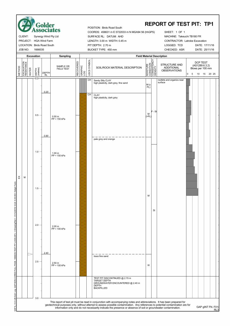
The foundation conditions encountered at Test Pits TP1 (Zone 1) and TP3 (Zone 2) which included firm clay

are unlikely to be suitable for use of pad footings to support wind turbines.

Where pad footings are an unsuitable footing option, it is envisaged that either driven precast concrete piles

or Continuous Flight Auger (CFA) piles could be used, with the turbine being supported on a pile cap. Given

the likely magnitude of the loads it is expected that multiple piles would be required for each footing. Based

upon the results of the desktop review and preliminary geotechnical investigation the Quaternary alluvial

soils may be expected to be only generally shallow, of less than about 5 m thickness. We would therefore

expect that the piles will need to be installed to found into the expected underlying higher strength soil or

rock, possibly being installed to reach effective refusal into dense or very dense Haunted Hill Gravels

materials or into rock of the Older Volcanics or Strezleki Group formations. Turbine locations where

foundations are expected to comprise a shallow thickness of alluvial soil and Haunted Hill Gravels materials

overlying Latrobe Valley Coal Measures materials (e.g. coal) are expected to require special consideration.

We would expect that founding piles in the Haunted Hill Gravels materials will be preferable to founding in

the underlying expected lower strength Latrobe Valley Coal Measures materials.

6.1.3 Preliminary Footing Design Parameters

6.1.3.1 Pad Footings

Table 4 presents indicative maximum ultimate bearing pressures that may be considered for preliminary design of pad footings for support of wind turbines. It should be noted that these pressures are related to the footing dimensions and the values will need to be confirmed once the actual loads on the structure are known and the footing sizes are assessed. These pressures are unfactored and appropriate geotechnical strength reduction factors or factors of safety will need to be applied for design of the footing.

HGA WIND FARM PRELIMINARY GEOTECHNICAL INVESTIGATION

17 January 2017 Report No. 1666035-001-R-Rev1 12

Table 4: Indicative Maximum Ultimate Bearing Pressures (Unfactored)

Founding Material Maximum Ultimate Bearing Pressure (kPa)

At least Medium Dense Sand/Silty Sand/Clayey Sand

400

Stiff or stronger Clay 300

6.1.3.2 Pile Footings

Given the presence of lower strength soils at typical pad founding depths and the relatively shallow

groundwater level piles could be used to increase the stiffness of the profile below the pad footing and to

increase the available bearing pressures (thereby reducing pad sizes). Either driven precast concrete piles

or CFA piles could be used which are installed to effective refusal into dense or very dense soil or rock or

potentially shallower depending upon the subsurface profile. Precast concrete piles in Victoria are typically

supplied with either 350 mm or 400 mm square cross sections. CFA piles are mostly constructed using 600

mm, 750 mm or 900 mm diameter augers. CFA piles therefore have the advantage of a larger cross

sectional area which increases the capacity of the piles.

For preliminary design of precast driven concrete piles installed to effective refusal, we recommend a

maximum allowable design working load of 1.5 MN for 350 mm square piles and 2 MN for 400 mm square

piles.

The successful installation of CFA piles and their ability to achieve stated design loads relies on the nature

and size of the equipment and procedures used in their installation. For preliminary design purposes, for

individual 600 mm, 750 mm and 900 mm diameter CFA piles installed to effective refusal we recommend

maximum design geotechnical strengths (factored ultimate axial load capacity) of 3 MN, 4.5 MN and 6 MN,

respectively.

The design loads achieved for driven precast piles and CFA piles will need to be confirmed by dynamic load

testing and subsequent CAPWAP analysis.

6.1.4 Possible founding conditions by zone

We understand Synergy Wind is considering potential turbine footing options including shallow pad or

deeper piled footings. The selection of a preferred footing option at each turbine location will depend on a

number of factors including the design loads to be supported, the likely founding materials for shallow and

deep founding options, groundwater conditions and constructability considerations. As requested by

Synergy Wind we have made a preliminary assessment of potential founding conditions that may be

encountered in each of the zones referred to in Section 5 with respect to the following founding

options/conditions:

pad footing with deep groundwater level

pad footing with shallow ground water level

pad footing combined with piles

For the purpose of assessing the likely shallow founding and groundwater conditions in each area we have

primarily relied on information obtained from the test pits excavated in each area. We note that the

subsurface conditions within each zone are likely to vary between turbine locations so the following

assessment should be considered preliminary only. Furthermore the pits, by their nature, have only

intersected the shallow soil profile. Table 5 presents a summary of turbine locations within each zone, a

summary of near surface soil and groundwater conditions encountered during the preliminary geotechnical

investigation and possible founding options that may be satisfactory.

HGA WIND FARM PRELIMINARY GEOTECHNICAL INVESTIGATION

17 January 2017 Report No. 1666035-001-R-Rev1 13

Table 5: Wind turbine zone and possible founding conditions/options

Zone Wind Turbine Numbers Summary shallow subsurface

conditions Possible founding options

1 T01 to T07 Firm to stiff clay

Shallow groundwater

Pad footing combined with piles

2 T08 to T11 Firm clay

Shallow groundwater

Pad footing combined with piles

3 T12 to T16, T18, T19, T22, T27, T31 to T34

Stiff clay / very dense clayey sand

Shallow groundwater

Pad footing combined with piles

4 T17, T24 to T26, T29

Stiff clay

Groundwater not encountered in test pit however historic bore information indicates the potential for shallow groundwater

Pad footing or pad footing combined with piles

5 T20, T21, T23, T28, T30

Very stiff clay

Groundwater not encountered in test pit however surface conditions in some areas were observed to be boggy

Pad footing or pad with piles

A more detailed assessment of footing options will need to be undertaken once information regarding design

loads is available and a detailed geotechnical investigation, including the drilling of deeper boreholes, has

been completed.

6.2 Crane Pads

At this time the size of cranes proposed for construction of the wind turbines and the magnitude of the likely

loads is unknown. It is expected that a crane pad to provide a working platform for the cranes will be

required at each turbine location. Crane pads will need to be constructed using VicRoads Class 4 crushed

rock or an equivalent quality locally quarried material. The thickness of crane pads required will depend on

the sizes of the cranes used and the ground bearing pressures imposed during lifting. Based on the ground

conditions assessed to date at the site, crane pads ranging up to about 1 m thickness are expected to be

required.

6.3 Road Design

It is expected that the project will involve the construction of a number of roads, some for construction

purposes and others for ongoing maintenance requirements. The construction traffic is likely to include cars,

utilities, four-wheel drive vehicles, large semi trailers, B-double, concrete trucks and large cranes. The post

construction traffic is expected to be limited to light vehicles and an occasional maintenance vehicle.

Pavement construction procedures would be likely to consist of stripping the surface topsoil prior to

placement of road pavement materials. The underlying subgrade will need to be proof rolled in order to

identify any unstable areas requiring treatment prior to pavement construction. We have noted during our

site visit that there are many poorly drained areas at this site, with some areas subject to flooding. It is

clearly preferable that construction of the roads for this project be planned for drier periods.

The pavement may be prone to erosion in periods of heavy rainfall. This may be particularly pronounced in

steeper sections of the roads. It will therefore be important that close attention is paid to drainage of the

pavements. The pavements should be designed to shed water and to the extent possible runoff should not

be allowed to form concentrated flows.

HGA WIND FARM PRELIMINARY GEOTECHNICAL INVESTIGATION

17 January 2017 Report No. 1666035-001-R-Rev1 14

The materials used for road construction are likely to consist of materials won from local borrow areas.

6.4 Further Investigations

The subsurface conditions across the site at the proposed wind turbine locations are expected to be

generally highly variable. To date, the geotechnical investigations performed have only extended to about

2.5 m depth. It is recommended that prior to detailed design borehole investigations are undertaken at each

turbine site to assess foundation conditions. The boreholes will need to extend to sufficient depth to

investigate suitable founding layers for the turbine footings. The investigations should include measurement

of groundwater depths.

7.0 IMPORTANT INFORMATION

Your attention is drawn to the document - ‘Important Information’ (LRG04, RL2) which is included in

Appendix B of this report. The statements presented in this document are intended to advise you of what

your realistic expectations of this report should be. The document is not intended to reduce the level of

responsibility accepted by Golder, but rather to ensure that all parties who may use this report aware of the

responsibilities each assumes in so doing.

We would be pleased to answer any questions the reader may have regarding this ‘Important Information’.

HGA WIND FARM PRELIMINARY GEOTECHNICAL INVESTIGATION

17 January 2017 Report No. 1666035-001-R-Rev1

Report Signature Page

GOLDER ASSOCIATES PTY LTD

Andrew Russell

Associate

IJH/ASR/ijh

A.B.N. 64 006 107 857

Golder, Golder Associates and the GA globe design are trademarks of Golder Associates Corporation.

j:\geo\2016\1666035 - synergy-wind, windfarm, gippsland\correspondence out\1666035-001-r-rev1.docx

TAP TAP ROAD

TELEGRAPH ROAD

MILL

ERS

HILL

ROAD

COAL

MIN

E RO

AD

MCGALLIARDS

ROAD

POUND ROAD W

JAME

SRO

AD

BIRD

S RO

AD S

LOWER JACKROAD

TELE

GRAP

HRO

AD

FOREST LODGEROAD

MEADOWS

ROAD

SOUTH GIPPSLAND HIGHWAY

WESTS ROAD

MURPHYS ROAD

NORT

H RO

AD

OLD ALBERTON WEST ROAD

BIRDSROAD

SILV

E RGA

TES

ROA D

BRAINS ROAD

NUGE

NTS R

OAD

TI TREE ROAD

ASKEWS ROAD

JAME

SRO

A DN

GELL

IOND

ALE

ROAD

MCPHAILS ROAD

BILLY CREEK ROAD

MCPHERSONSROADPEARSONS

ROAD

T01

T02

T03

T04

T05

T06

T07

T08

T09

T10T11

T12

T13

T14

T15

T16

T17

T18

T19

T20

T21

T22

T23

T24

T25

T26

T27

T28

T29

T30

T31

T32

T33

T34

Source: Esri, DigitalGlobe, GeoEye, Earthstar Geographics, CNES/Airbus DS, USDA, USGS, AEX,Getmapping, Aerogrid, IGN, IGP, swisstopo, and the GIS User Community

CLIENTSYNERGY WIND PTY LTD

LEGEND

Proposed Wind Turbine Site Property Boundary PROJECT

TITLESITE LOCATION AND LAYOUT

1666035 001-R 0 1

2/12/2016 AFE-ASRASR

Path: J: \Geo\2016\1666035 - Synergy -wind, W indfarm , Gipps land\Technical D oc\GIS\Projec t\1666035-001-R-F0001-R ev0.mxd

LOCATION MAP

IF TH

IS M

EASU

REME

NT D

OES

NOT

MATC

H W

HAT I

S SH

OWN,

THE

SHE

ET S

IZE

HAS

BEEN

MOD

IFIE

D FR

OM: A

3

HGA WIND FARM, SOUTH GIPPSLAND -PRELIMINARY GEOTECHNICAL INVESTIGATION

CONSULTANT

PROJECT No. CONTROL REVIEW FIGURE

YYYY-MM-DDPREPAREDDESIGNREVIEWAPPROVED

25m

m0

0 500 1,000 1,500 2,000

METR ES

PROJECTION: GDA 1994 MGA Zone 55 REFERENCE SCALE: 1:40,000 (at A3)

ED

ED

ED

ED

ED

ED

TAP TAP ROAD

TELEGRAPH ROAD

COA L

M INE

ROA D

POUND ROAD W

JAME

SRO

AD

BIRD

S RO

AD S

LOWER JACK ROAD

TELE

GRAP

HRO

AD

SOUTH GIPPSLAND HIGHWAY

WESTS ROAD

MURPHYS ROAD

NORT

H RO

AD

OLD ALBERTON WEST ROAD

BIRDSROAD

BRAINS ROAD

NUGE

NTS

ROAD

TI TREE ROAD

ASKEWS ROAD

GELL

IOND

ALE

ROAD

MCPHAILS ROAD

BILLY CREEK ROADPEARSONS ROAD

T01

T02

T03

T04

T05

T06

T07

T08

T09

T10 T11

T12

T13

T14

T15

T16

T17

T18

T19

T20

T21

T22

T23

T24

T25

T26

T27

T28

T29

T30

T31

T32

T33

T34

Zone 5

Zone 4

Zone 2

Zone 2

Zone 3

Zone 1TP01

TP03

TP04

TP05

TP06

TP07

Source: Esri, DigitalGlobe, GeoEye, Earthstar Geographics, CNES/Airbus DS, USDA, USGS, AEX,Getmapping, Aerogrid, IGN, IGP, swisstopo, and the GIS User Community

CLIENTSYNERGY WIND PTY LTD

LEGENDED Approximate Test Pit Location Proposed Wind Turbine

Wind Farm ZoneSite Property Boundary

PROJECT

TITLETEST PIT PLAN

1666035 001-R 0 2

2/12/2016 AFE-ASRASR

Path: J: \Geo\2016\1666035 - Synergy -wind, W indfarm , Gipps land\Technical D oc\GIS\Projec t\1666035-001-R-F0002-R ev0.mxd

LOCATION MAP

IF TH

IS M

EASU

REME

NT D

OES

NOT

MATC

H W

HAT I

S SH

OWN,

THE

SHE

ET S

IZE

HAS

BEEN

MOD

IFIE

D FR

OM: A

3

HGA WIND FARM, SOUTH GIPPSLAND -PRELIMINARY GEOTECHNICAL INVESTIGATION

CONSULTANT

PROJECT No. CONTROL REVIEW FIGURE

YYYY-MM-DDPREPAREDDESIGNREVIEWAPPROVED

25m

m0

0 500 1,000 1,500 2,000

METR ES

PROJECTION: GDA 1994 MGA Zone 55 REFERENCE SCALE: 1:40,000 (at A3)

ED

ED

ED

ED

ED

ED

TP07

TP06

TP05

TP04TP03

TP01

Zone 3

Zone 4

Zone 1

Zone 5

Zone 2

Zone 2

T34

T33T32

T31

T30

T29

T28

T27

T26

T25

T24

T23

T22

T21

T20

T19

T18

T17

T16

T15

T14

T13T12

T11

T10

T09

T08T07

T06

T05

T04

T03

T02

T01

CLIENTSYNERGY WIND PTY LTD

LEGENDED Approximate Test Pit Location Proposed Wind Turbine

Wind Farm ZoneSite Location

COPYRIGHTRegional Geology (c) Geological Survey of Victoria

1:50,000 Series - Map 001 'Alberton'.

PROJECT

TITLEWIND TURBINE LOCATION AND REGIONAL GEOLOGY

1666035 001-R 0 3

2/12/2016 AFE-ASRASR

Path: J: \Geo\2016\1666035 - Synergy -wind, W indfarm , Gipps land\Technical D oc\GIS\Projec t\1666035-001-R-F0003-R ev0.mxd

LOCATION MAP

IF TH

IS M

EASU

REME

NT D

OES

NOT

MATC

H W

HAT I

S SH

OWN,

THE

SHE

ET S

IZE

HAS

BEEN

MOD

IFIE

D FR

OM: A

3

HGA WIND FARM, SOUTH GIPPSLAND -PRELIMINARY GEOTECHNICAL INVESTIGATION

CONSULTANT

PROJECT No. CONTROL REVIEW FIGURE

YYYY-MM-DDPREPAREDDESIGNREVIEWAPPROVED

25m

m0

0 500 1,000 1,500 2,000

METR ES

PROJECTION: GDA 1994 MGA Zone 55 REFERENCE SCALE: 1:50,000 (at A3)

HGA WIND FARM PRELIMINARY GEOTECHNICAL INVESTIGATION

17 January 2017 Report No. 1666035-001-R-Rev1

APPENDIX A Reports of Test Pits TP1 and TP3 to TP7 Photographs of Test Pits TP1 and TP3 to TP7 Explanation of notes, abbreviations and terms used on borehole and test pit reports Method of soil description used on borehole and test pit reports

M

Sandy Silty CLAYhigh plasticity, dark grey, fine sand

CLAYhigh plasticity, dark grey

pale grey and orange

trace fine sand

TEST PIT DISCONTINUED @ 2.70 mTARGET DEPTHGROUNDWATER ENCOUNTERED @ 2.40 mDEPTHBACKFILLED

CH

CH0.20

0.80

2.40

EX

0.50 mPP = 150 kPa

1.00 mPP = 150 kPa

2.00 mPP = 100 kPa

2.50 mPP = 100 kPa

M (cPL)

M(>PL)

M

W

F - St

St

rootlets and organics nearsurface

SHEET: 1 OF 1

Field Material DescriptionSamplingExcavation

EX

CA

VA

TIO

NR

ES

IST

AN

CE

SOIL/ROCK MATERIAL DESCRIPTION

US

CS

SY

MB

OL

RE

CO

VE

RE

D

WA

TE

R

RLDEPTH

DE

PT

H(m

etre

s)

ME

TH

OD

GR

AP

HIC

LOG

SAMPLE ORFIELD TEST

GAP gINT FN. F01iRL3

CLIENT:

PROJECT:

LOCATION:

JOB NO:

DATE: 17/11/16

DATE: 25/11/16

This report of test pit must be read in conjunction with accompanying notes and abbreviations. It has been prepared forgeotechnical purposes only, without attempt to assess possible contamination. Any references to potential contamination are for

information only and do not necessarily indicate the presence or absence of soil or groundwater contamination.

REPORT OF TEST PIT: TP1

Synergy Wind Pty Ltd

HGA Wind Farm

Birds Road South

1666035

POSITION: Birds Road South

COORDS: 458631 m E 5722033 m N MGA94 56 (hhGPS)

SURFACE RL: DATUM: AHD

LENGTH: 3.00 m WIDTH: 0.45 m

PIT DEPTH: 2.70 m

BUCKET TYPE: 450 mm

MACHINE: Takeuchi TB180 FR

CONTRACTOR: Latrobe Excavation

LOGGED: TCD

CHECKED: ASR

GA

P 8

_13.

0 LI

B.G

LB L

og G

AP

NO

N-C

OR

ED

FU

LL P

AG

E 1

6660

35-

TE

ST

PIT

LO

GS

.GP

J <

<D

raw

ingF

ile>

> 0

1/12

/201

6 14

:24

8.3

0.00

3 D

atge

l Too

ls

MO

IST

UR

EC

ON

DIT

ION

CO

NS

IST

EN

CY

DE

NS

ITY

DCP TEST(AS1289.6.3.2)

Blows per 100 mm

5 10 15 200 25

STRUCTURE ANDADDITIONAL

OBSERVATIONS

0.0

0.5

1.0

1.5

2.0

2.5

3.0

1.

2.

SHEET: 1 OF 1

GAP gINT FN. F27RL1

CLIENT:

PROJECT:

LOCATION:

JOB NO:

DATE: 17/11/16

DATE: 25/11/16

This report of test pit photographs must be read in conjunction with accompanying notes and abbreviations. It has been preparedfor geotechnical purposes only, without attempt to assess possible contamination. Any references to potential contamination are

for information only and do not necessarily indicate the presence or absence of soil or groundwater contamination.

REPORT OF TEST PIT PHOTOGRAPHS: TP1

Synergy Wind Pty Ltd

HGA Wind Farm

Birds Road South

1666035

POSITION: Birds Road South

COORDS: 458631 m E 5722033 m N MGA94 56 (hhGPS)

SURFACE RL: DATUM: AHD

LENGTH: 3.00 m WIDTH: 0.45 m

PIT DEPTH: 2.70 m

BUCKET TYPE: 450 mm

MACHINE: Takeuchi TB180 FR

CONTRACTOR: Latrobe Excavation

LOGGED: TCD

CHECKED: ASR

GA

P 8

_13.

0 LI

B.G

LB G

rfcT

bl G

AP

TE

ST

PIT

PH

OT

O 2

PE

R P

AG

E 1

6660

35-

TE

ST

PIT

LO

GS

.GP

J <

<D

raw

ingF

ile>

> 0

1/12

/201

6 14

:34

8.3

0.00

3 D

atge

l Too

ls

M

L

Sandy Silty CLAYhigh plasticity, dark grey, fine sand

CLAYhigh plasticity, dark grey

grey and orange

TEST PIT DISCONTINUED @ 2.60 mTARGET DEPTHGROUNDWATER ENCOUNTERED @ 1.90 mDEPTHBACKFILLED

CH

CH0.20

1.00

EX

0.50 mPP = 100 kPa

1.00 mPP = 100 kPa

2.00 mPP = 50 kPa

M (cPL)

M(>PL)

W

F - St

F

rootlets and organics nearsurface

SHEET: 1 OF 1

Field Material DescriptionSamplingExcavation

EX

CA

VA

TIO

NR

ES

IST

AN

CE

SOIL/ROCK MATERIAL DESCRIPTION

US

CS

SY

MB

OL

RE

CO

VE

RE

D

WA

TE

R

RLDEPTH

DE

PT

H(m

etre

s)

ME

TH

OD

GR

AP

HIC

LOG

SAMPLE ORFIELD TEST

GAP gINT FN. F01iRL3

CLIENT:

PROJECT:

LOCATION:

JOB NO:

DATE: 17/11/16

DATE: 25/11/16

This report of test pit must be read in conjunction with accompanying notes and abbreviations. It has been prepared forgeotechnical purposes only, without attempt to assess possible contamination. Any references to potential contamination are for

information only and do not necessarily indicate the presence or absence of soil or groundwater contamination.

REPORT OF TEST PIT: TP3

Synergy Wind Pty Ltd

HGA Wind Farm

South Gippsland Hwy

1666035

POSITION: South Gippsland Hwy

COORDS: 462825 m E 5723740 m N MGA94 56 (hhGPS)

SURFACE RL: DATUM: AHD

LENGTH: 3.00 m WIDTH: 0.50 m

PIT DEPTH: 2.60 m

BUCKET TYPE: 450 mm

MACHINE: Takeuchi TB180 FR

CONTRACTOR: Latrobe Excavation

LOGGED: TCD

CHECKED: ASR

GA

P 8

_13.

0 LI

B.G

LB L

og G

AP

NO

N-C

OR

ED

FU

LL P

AG

E 1

6660

35-

TE

ST

PIT

LO

GS

.GP

J <

<D

raw

ingF

ile>

> 0

1/12

/201

6 14

:24

8.3

0.00

3 D

atge

l Too

ls

MO

IST

UR

EC

ON

DIT

ION

CO

NS

IST

EN

CY

DE

NS

ITY

DCP TEST(AS1289.6.3.2)

Blows per 100 mm

5 10 15 200 25

STRUCTURE ANDADDITIONAL

OBSERVATIONS

0.0

0.5

1.0

1.5

2.0

2.5

3.0

1.

2.

SHEET: 1 OF 1

GAP gINT FN. F27RL1

CLIENT:

PROJECT:

LOCATION:

JOB NO:

DATE: 17/11/16

DATE: 25/11/16

This report of test pit photographs must be read in conjunction with accompanying notes and abbreviations. It has been preparedfor geotechnical purposes only, without attempt to assess possible contamination. Any references to potential contamination are

for information only and do not necessarily indicate the presence or absence of soil or groundwater contamination.

REPORT OF TEST PIT PHOTOGRAPHS: TP3

Synergy Wind Pty Ltd

HGA Wind Farm

South Gippsland Hwy

1666035

POSITION: South Gippsland Hwy

COORDS: 462825 m E 5723740 m N MGA94 56 (hhGPS)

SURFACE RL: DATUM: AHD

LENGTH: 3.00 m WIDTH: 0.50 m

PIT DEPTH: 2.60 m

BUCKET TYPE: 450 mm

MACHINE: Takeuchi TB180 FR

CONTRACTOR: Latrobe Excavation

LOGGED: TCD

CHECKED: ASR

GA

P 8

_13.

0 LI

B.G

LB G

rfcT

bl G

AP

TE

ST

PIT

PH

OT

O 2

PE

R P

AG

E 1

6660

35-

TE

ST

PIT

LO

GS

.GP

J <

<D

raw

ingF

ile>

> 0

1/12

/201

6 14

:35

8.3

0.00

3 D

atge

l Too

ls

L

M

L

Silty SANDfine to medium grained, dark grey

SANDfine to medium grained, yellow grey, trace silt

Sandy CLAYhigh plasticity, orange grey, fine sand

SANDfine to medium grained, yellow pale grey, withsome silt

Clayey SANDfine to medium grained, yellow pale grey, highplasticity clay

TEST PIT DISCONTINUED @ 2.50 mTARGET DEPTHGROUNDWATER NOT OBSERVEDBACKFILLED

SW-SM

SW

CH

SW

0.20

0.50

1.40

2.40

EX

M

M(>PL)

M

MD -D

St

VD

rootlets and organics nearsurface

SHEET: 1 OF 1

Field Material DescriptionSamplingExcavation

EX

CA

VA

TIO

NR

ES

IST

AN

CE

SOIL/ROCK MATERIAL DESCRIPTION

US

CS

SY

MB

OL

RE

CO

VE

RE

D

WA

TE

R

RLDEPTH

DE

PT

H(m

etre

s)

ME

TH

OD

GR

AP

HIC

LOG

SAMPLE ORFIELD TEST

GAP gINT FN. F01iRL3

CLIENT:

PROJECT:

LOCATION:

JOB NO:

DATE: 17/11/16

DATE: 25/11/16

This report of test pit must be read in conjunction with accompanying notes and abbreviations. It has been prepared forgeotechnical purposes only, without attempt to assess possible contamination. Any references to potential contamination are for

information only and do not necessarily indicate the presence or absence of soil or groundwater contamination.

REPORT OF TEST PIT: TP4

Synergy Wind Pty Ltd

HGA Wind Farm

South Gippsland Hwy

1666035

POSITION: South Gippsland Hwy

COORDS: 466154 m E 5723370 m N MGA94 56 (hhGPS)

SURFACE RL: DATUM: AHD

LENGTH: 3.00 m WIDTH: 0.50 m

PIT DEPTH: 2.50 m

BUCKET TYPE: 450 mm

MACHINE: Takeuchi TB180 FR

CONTRACTOR: Latrobe Excavation

LOGGED: TCD

CHECKED: ASR

GA

P 8

_13.

0 LI

B.G

LB L

og G

AP

NO

N-C

OR

ED

FU

LL P

AG

E 1

6660

35-

TE

ST

PIT

LO

GS

.GP

J <

<D

raw

ingF

ile>

> 0

1/12

/201

6 14

:24

8.3

0.00

3 D

atge

l Too

ls

MO

IST

UR

EC

ON

DIT

ION

CO

NS

IST

EN

CY

DE

NS

ITY

DCP TEST(AS1289.6.3.2)

Blows per 100 mm

5 10 15 200 25

STRUCTURE ANDADDITIONAL

OBSERVATIONS

0.0

0.5

1.0

1.5

2.0

2.5

3.0

1.

2.

SHEET: 1 OF 1

GAP gINT FN. F27RL1

CLIENT:

PROJECT:

LOCATION:

JOB NO:

DATE: 17/11/16

DATE: 25/11/16

This report of test pit photographs must be read in conjunction with accompanying notes and abbreviations. It has been preparedfor geotechnical purposes only, without attempt to assess possible contamination. Any references to potential contamination are

for information only and do not necessarily indicate the presence or absence of soil or groundwater contamination.

REPORT OF TEST PIT PHOTOGRAPHS: TP4

Synergy Wind Pty Ltd

HGA Wind Farm

South Gippsland Hwy

1666035

POSITION: South Gippsland Hwy

COORDS: 466154 m E 5723370 m N MGA94 56 (hhGPS)

SURFACE RL: DATUM: AHD

LENGTH: 3.00 m WIDTH: 0.50 m

PIT DEPTH: 2.50 m

BUCKET TYPE: 450 mm

MACHINE: Takeuchi TB180 FR

CONTRACTOR: Latrobe Excavation

LOGGED: TCD

CHECKED: ASR

GA

P 8

_13.

0 LI

B.G

LB G

rfcT

bl G

AP

TE

ST

PIT

PH

OT

O 2

PE

R P

AG

E 1

6660

35-

TE

ST

PIT

LO

GS

.GP

J <

<D

raw

ingF

ile>

> 0

1/12

/201

6 14

:35

8.3

0.00

3 D

atge

l Too

ls

L

Silty Sandy CLAYhigh plasticity, dark grey, fine sand

CLAYhigh plasticity, orange and pale grey, with somefine sand

Clayey SANDfine to coarse grained, orange, high plasticity clay

TEST PIT DISCONTINUED @ 2.60 mTARGET DEPTHGROUNDWATER ENCOUNTERED @ 2.40 mDEPTHBACKFILLED

CH

CH

SW

0.40

2.40

EX

0.50 mPP = 150 kPa

1.00 mPP = 100 kPa

M (cPL)

M(>PL)

W

F

St

VD

rootlets and organics nearsurface

300 mm of wateraccumulated in base of testpit after 45 min

SHEET: 1 OF 1

Field Material DescriptionSamplingExcavation

EX

CA

VA

TIO

NR

ES

IST

AN

CE

SOIL/ROCK MATERIAL DESCRIPTION

US

CS

SY

MB

OL

RE

CO

VE

RE

D

WA

TE

R

RLDEPTH

DE

PT

H(m

etre

s)

ME

TH

OD

GR

AP

HIC

LOG

SAMPLE ORFIELD TEST

GAP gINT FN. F01iRL3

CLIENT:

PROJECT:

LOCATION:

JOB NO:

DATE: 17/11/16

DATE: 25/11/16

This report of test pit must be read in conjunction with accompanying notes and abbreviations. It has been prepared forgeotechnical purposes only, without attempt to assess possible contamination. Any references to potential contamination are for

information only and do not necessarily indicate the presence or absence of soil or groundwater contamination.

REPORT OF TEST PIT: TP5

Synergy Wind Pty Ltd

HGA Wind Farm

Ti Tree Road

1666035

POSITION: Ti Tree Road

COORDS: 468816 m E 5724475 m N MGA94 56 (hhGPS)

SURFACE RL: DATUM: AHD

LENGTH: 3.00 m WIDTH: 0.50 m

PIT DEPTH: 2.60 m

BUCKET TYPE: 450 mm

MACHINE: Takeuchi TB180 FR

CONTRACTOR: Latrobe Excavation

LOGGED: TCD

CHECKED: ASR

GA

P 8

_13.

0 LI

B.G

LB L

og G

AP

NO

N-C

OR

ED

FU

LL P

AG

E 1

6660

35-

TE

ST

PIT

LO

GS

.GP

J <

<D

raw

ingF

ile>

> 0

1/12

/201

6 14

:24

8.3

0.00

3 D

atge

l Too

ls

MO

IST

UR

EC

ON

DIT

ION

CO

NS

IST

EN

CY

DE

NS

ITY

DCP TEST(AS1289.6.3.2)

Blows per 100 mm

5 10 15 200 25

STRUCTURE ANDADDITIONAL

OBSERVATIONS

0.0

0.5

1.0

1.5

2.0

2.5

3.0

1.

2.

SHEET: 1 OF 1

GAP gINT FN. F27RL1

CLIENT:

PROJECT:

LOCATION:

JOB NO:

DATE: 17/11/16

DATE: 25/11/16

This report of test pit photographs must be read in conjunction with accompanying notes and abbreviations. It has been preparedfor geotechnical purposes only, without attempt to assess possible contamination. Any references to potential contamination are

for information only and do not necessarily indicate the presence or absence of soil or groundwater contamination.

REPORT OF TEST PIT PHOTOGRAPHS: TP5

Synergy Wind Pty Ltd

HGA Wind Farm

Ti Tree Road

1666035

POSITION: Ti Tree Road

COORDS: 468816 m E 5724475 m N MGA94 56 (hhGPS)

SURFACE RL: DATUM: AHD

LENGTH: 3.00 m WIDTH: 0.50 m

PIT DEPTH: 2.60 m

BUCKET TYPE: 450 mm

MACHINE: Takeuchi TB180 FR

CONTRACTOR: Latrobe Excavation

LOGGED: TCD

CHECKED: ASR

GA

P 8

_13.

0 LI

B.G

LB G

rfcT

bl G

AP

TE

ST

PIT

PH

OT

O 2

PE

R P

AG

E 1

6660

35-

TE

ST

PIT

LO

GS

.GP

J <

<D

raw

ingF

ile>

> 0

1/12

/201

6 14

:35

8.3

0.00

3 D

atge

l Too

ls

M

Sandy Silty CLAYhigh plasticity, dark grey, fine sand

CLAYhigh plasticity, dark grey

pale grey and orange

TEST PIT DISCONTINUED @ 2.50 mTARGET DEPTHGROUNDWATER NOT OBSERVEDBACKFILLED

CH

CH0.30

0.60

EX

0.40 mPP = 250 kPa

0.80 mPP = 150 kPa

1.50 mPP = 200 kPa

2.00 mPP = 150 kPa

M (cPL)

M (cPL)

M(>PL)

St

rootlets and organics nearsurface

SHEET: 1 OF 1

Field Material DescriptionSamplingExcavation

EX

CA

VA

TIO

NR

ES

IST

AN

CE

SOIL/ROCK MATERIAL DESCRIPTION

US

CS

SY

MB

OL

RE

CO

VE

RE

D

WA

TE

R

RLDEPTH

DE

PT

H(m

etre

s)

ME

TH

OD

GR

AP

HIC

LOG

SAMPLE ORFIELD TEST

GAP gINT FN. F01iRL3

CLIENT:

PROJECT:

LOCATION:

JOB NO:

DATE: 17/11/16

DATE: 25/11/16

This report of test pit must be read in conjunction with accompanying notes and abbreviations. It has been prepared forgeotechnical purposes only, without attempt to assess possible contamination. Any references to potential contamination are for

information only and do not necessarily indicate the presence or absence of soil or groundwater contamination.

REPORT OF TEST PIT: TP6

Synergy Wind Pty Ltd

HGA Wind Farm

Old Alberton West Road

1666035

POSITION: Old Alberton West Road

COORDS: 466479 m E 5726274 m N MGA94 56 (hhGPS)

SURFACE RL: DATUM: AHD

LENGTH: 3.00 m WIDTH: 0.50 m

PIT DEPTH: 2.50 m

BUCKET TYPE: 450 mm

MACHINE: Takeuchi TB180 FR

CONTRACTOR: Latrobe Excavation

LOGGED: TCD

CHECKED: ASR

GA

P 8

_13.

0 LI

B.G

LB L

og G

AP

NO

N-C

OR

ED

FU

LL P

AG

E 1

6660

35-

TE

ST

PIT

LO

GS

.GP

J <

<D

raw

ingF

ile>

> 0

1/12

/201

6 14

:24

8.3

0.00

3 D

atge

l Too

ls

MO

IST

UR

EC

ON

DIT

ION

CO

NS

IST

EN

CY

DE

NS

ITY

DCP TEST(AS1289.6.3.2)

Blows per 100 mm

5 10 15 200 25

STRUCTURE ANDADDITIONAL

OBSERVATIONS

0.0

0.5

1.0

1.5

2.0

2.5

3.0

1.

2.

SHEET: 1 OF 1

GAP gINT FN. F27RL1

CLIENT:

PROJECT:

LOCATION:

JOB NO:

DATE: 17/11/16

DATE: 25/11/16

This report of test pit photographs must be read in conjunction with accompanying notes and abbreviations. It has been preparedfor geotechnical purposes only, without attempt to assess possible contamination. Any references to potential contamination are

for information only and do not necessarily indicate the presence or absence of soil or groundwater contamination.

REPORT OF TEST PIT PHOTOGRAPHS: TP6

Synergy Wind Pty Ltd

HGA Wind Farm

Old Alberton West Road

1666035

POSITION: Old Alberton West Road

COORDS: 466479 m E 5726274 m N MGA94 56 (hhGPS)

SURFACE RL: DATUM: AHD

LENGTH: 3.00 m WIDTH: 0.50 m

PIT DEPTH: 2.50 m

BUCKET TYPE: 450 mm

MACHINE: Takeuchi TB180 FR

CONTRACTOR: Latrobe Excavation

LOGGED: TCD

CHECKED: ASR

GA

P 8

_13.

0 LI

B.G

LB G

rfcT

bl G

AP

TE

ST

PIT

PH

OT

O 2

PE

R P

AG

E 1

6660

35-

TE

ST

PIT

LO

GS

.GP

J <

<D

raw

ingF

ile>

> 0

1/12

/201

6 14

:35

8.3

0.00

3 D

atge

l Too

ls

L

M

Sandy Silty CLAYhigh plasticity, dark grey

CLAYhigh plasticity, dark grey

orange and pale grey

TEST PIT DISCONTINUED @ 2.50 mTARGET DEPTHGROUNDWATER NOT OBSERVEDBACKFILLED

CH

CH0.20

0.50

EX

0.60 mPP = 150 kPa

1.80 mPP = 200 kPa

2.50 mPP = 250 kPa

M

M(>PL)

F

St

VSt

rootlets and organics nearsurface

SHEET: 1 OF 1

Field Material DescriptionSamplingExcavation

EX

CA

VA

TIO

NR

ES

IST

AN

CE

SOIL/ROCK MATERIAL DESCRIPTION

US

CS

SY

MB

OL

RE

CO

VE

RE

D

WA

TE

R

RLDEPTH

DE

PT

H(m

etre

s)

ME

TH

OD

GR

AP

HIC

LOG

SAMPLE ORFIELD TEST

GAP gINT FN. F01iRL3

CLIENT:

PROJECT:

LOCATION:

JOB NO:

DATE: 17/11/16

DATE: 25/11/16

This report of test pit must be read in conjunction with accompanying notes and abbreviations. It has been prepared forgeotechnical purposes only, without attempt to assess possible contamination. Any references to potential contamination are for

information only and do not necessarily indicate the presence or absence of soil or groundwater contamination.

REPORT OF TEST PIT: TP7

Synergy Wind Pty Ltd

HGA Wind Farm

Pond Road West

1666035

POSITION: Pond Road West

COORDS: 467624 m E 5729643 m N MGA94 56 (hhGPS)

SURFACE RL: DATUM: AHD

LENGTH: 3.00 m WIDTH: 0.50 m

PIT DEPTH: 2.50 m

BUCKET TYPE: 450 mm

MACHINE: Takeuchi TB180 FR

CONTRACTOR: Latrobe Excavation

LOGGED: TCD

CHECKED: ASR

GA

P 8

_13.

0 LI

B.G

LB L

og G

AP

NO

N-C

OR

ED

FU

LL P

AG

E 1

6660

35-

TE

ST

PIT

LO

GS

.GP

J <

<D

raw

ingF

ile>

> 0

1/12

/201

6 14

:24

8.3

0.00

3 D

atge

l Too

ls

MO

IST

UR

EC

ON

DIT

ION

CO

NS

IST

EN

CY

DE

NS

ITY

DCP TEST(AS1289.6.3.2)

Blows per 100 mm

5 10 15 200 25

STRUCTURE ANDADDITIONAL

OBSERVATIONS

0.0

0.5

1.0

1.5

2.0

2.5

3.0

1.

2.

SHEET: 1 OF 1

GAP gINT FN. F27RL1

CLIENT:

PROJECT:

LOCATION:

JOB NO:

DATE: 17/11/16

DATE: 25/11/16

This report of test pit photographs must be read in conjunction with accompanying notes and abbreviations. It has been preparedfor geotechnical purposes only, without attempt to assess possible contamination. Any references to potential contamination are

for information only and do not necessarily indicate the presence or absence of soil or groundwater contamination.

REPORT OF TEST PIT PHOTOGRAPHS: TP7

Synergy Wind Pty Ltd

HGA Wind Farm

Pond Road West

1666035

POSITION: Pond Road West

COORDS: 467624 m E 5729643 m N MGA94 56 (hhGPS)

SURFACE RL: DATUM: AHD

LENGTH: 3.00 m WIDTH: 0.50 m

PIT DEPTH: 2.50 m

BUCKET TYPE: 450 mm

MACHINE: Takeuchi TB180 FR

CONTRACTOR: Latrobe Excavation

LOGGED: TCD

CHECKED: ASR

GA

P 8

_13.

0 LI

B.G

LB G

rfcT

bl G

AP

TE

ST

PIT

PH

OT

O 2

PE

R P

AG

E 1

6660

35-

TE

ST

PIT

LO

GS

.GP

J <

<D

raw

ingF

ile>

> 0

1/12

/201

6 14

:35

8.3

0.00

3 D

atge

l Too

ls

GAP Form No. 6 RL7 August 2010

EXPLANATION OF NOTES, ABBREVIATIONS & TERMS USED ON BOREHOLE AND TEST PIT REPORTS

DRILLING/EXCAVATION METHOD AS* Auger Screwing RD Rotary blade or drag bit NQ Diamond Core - 47 mm AD* Auger Drilling RT Rotary Tricone bit NMLC Diamond Core - 52 mm *V V-Bit RAB Rotary Air Blast HQ Diamond Core - 63 mm *T TC-Bit, e.g. ADT RC Reverse Circulation HMLC Diamond Core – 63mm HA Hand Auger PT Push Tube BH Tractor Mounted Backhoe ADH Hollow Auger CT Cable Tool Rig EX Tracked Hydraulic Excavator DTC Diatube Coring JET Jetting EE Existing Excavation WB Washbore or Bailer NDD Non-destructive digging HAND Excavated by Hand Methods PENETRATION/EXCAVATION RESISTANCE

L Low resistance. Rapid penetration possible with little effort from the equipment used. M Medium resistance. Excavation/possible at an acceptable rate with moderate effort from the equipment used. H High resistance to penetration/excavation. Further penetration is possible at a slow rate and requires significant

effort from the equipment. R Refusal or Practical Refusal. No further progress possible without the risk of damage or unacceptable wear to the

digging implement or machine. These assessments are subjective and are dependent on many factors including the equipment power, weight, condition of excavation or drilling tools, and the experience of the operator. WATER

Water level at date shown Partial water loss Water inflow Complete water loss

GROUNDWATER NOT OBSERVED

The observation of groundwater, whether present or not, was not possible due to drilling water, surface seepage or cave in of the borehole/test pit.

GROUNDWATER NOT ENCOUNTERED

The borehole/test pit was dry soon after excavation. However, groundwater could be present in less permeable strata. Inflow may have been observed had the borehole/test pit been left open for a longer period.

SAMPLING AND TESTING SPT 4,7,11 N=18 30/80mm RW HW HB

Standard Penetration Test to AS1289.6.3.1-2004 4,7,11 = Blows per 150mm. N = Blows per 300mm penetration following 150mm seating Where practical refusal occurs, the blows and penetration for that interval are reported Penetration occurred under the rod weight only Penetration occurred under the hammer and rod weight only Hammer double bouncing on anvil

DS Disturbed sample BDS Bulk disturbed sample G Gas Sample W Water Sample FP Field permeability test over section noted FV Field vane shear test expressed as uncorrected shear strength (sv = peak value, sr = residual value) PID Photoionisation Detector reading in ppm PM Pressuremeter test over section noted PP Pocket penetrometer test expressed as instrument reading in kPa U63 Thin walled tube sample - number indicates nominal sample diameter in millimetres WPT Water pressure tests DCP Dynamic cone penetration test CPT Static cone penetration test CPTu Static cone penetration test with pore pressure (u) measurement Ranking of Visually Observable Contamination and Odour (for specific soil contamination assessment projects)

R = 0 R = 1 R = 2 R = 3

No visible evidence of contamination Slight evidence of visible contamination Visible contamination Significant visible contamination

R = A R = B R = C R = D

No non-natural odours identified Slight non-natural odours identified Moderate non-natural odours identified Strong non-natural odours identified

ROCK CORE RECOVERY TCR = Total Core Recovery (%) SCR = Solid Core Recovery (%) RQD = Rock Quality Designation (%)

100runcoreofLengtheredcovrecoreofLength

100runcoreofLengtheredcovrecorelcylindricaofLength

100runcoreofLengthmm100coreoflengthsAxial

GAP Form No. 5 RL8

METHOD OF SOIL DESCRIPTION USED ON BOREHOLE AND TEST PIT REPORTS

Combinations of these basic symbols may be used to indicate mixed materials such as sandy clay. CLASSIFICATION AND INFERRED STRATIGRAPHY Soil and Rock is classified and described in Reports of Boreholes and Test Pits using the preferred method given in AS1726 – 1993, (Amdt1 – 1994 and Amdt2 – 1994), Appendix A. The material properties are assessed in the field by visual/tactile methods.

Particle Size Plasticity Properties

Major Division Sub Division Particle Size

BOULDERS > 200 mm COBBLES 63 to 200 mm

Coarse 20 to 63 mm Medium 6.0 to 20 mm GRAVEL

Fine 2.0 to 6.0 mm Coarse 0.6 to 2.0 mm Medium 0.2 to 0.6 mm SAND

Fine 0.075 to 0.2 mm SILT 0.002 to 0.075 mm CLAY < 0.002 mm

0

10

20

30

40

0 10 20 30 40 50 60 70 80Liquid Limit (%)

Plas

ticity

Inde

x (%

)

MOISTURE CONDITION AS1726 - 1993 Symbol Term Description

D Dry Sands and gravels are free flowing. Clays & Silts may be brittle or friable and powdery. M Moist Soils are darker than in the dry condition & may feel cool. Sands and gravels tend to cohere. W Wet Soils exude free water. Sands and gravels tend to cohere.

CONSISTENCY AND DENSITY AS1726 - 1993 Symbol Term Undrained Shear

Strength Symbol Term Density Index % SPT “N” #

VS Very Soft 0 to 12 kPa VL Very Loose Less than 15 0 to 4 S Soft 12 to 25 kPa L Loose 15 to 35 4 to 10 F Firm 25 to 50 kPa MD Medium Dense 35 to 65 10 to 30 St Stiff 50 to 100 kPa D Dense 65 to 85 30 to 50

VSt Very Stiff 100 to 200 kPa VD Very Dense Above 85 Above 50 H Hard Above 200 kPa

In the absence of test results, consistency and density may be assessed from correlations with the observed behaviour of the material. # SPT correlations are not stated in AS1726 – 1993, and may be subject to corrections for overburden pressure and equipment type.

FILL

GRAVEL (GP or GW)

SAND (SP or SW)

SILT (ML or MH)

CLAY (CL, CI or CH)

ORGANIC SOILS (OL or OH or Pt)

COBBLES or BOULDERS

CL Low plasticity

clay

CL/ML Clay/Silt OL or ML - Low liquid limit silt

CI Medium plasticity

clay

CH High plasticity

clay

OH or MH High liquid limit

silt

OL or ML Low liquid

limit silt

HGA WIND FARM PRELIMINARY GEOTECHNICAL INVESTIGATION

17 January 2017 Report No. 1666035-001-R-Rev1

APPENDIX B Important information

IMPORTANT INFORMATION RELATING TO THIS REPORT

The document (“Report”) to which this page is attached and which this page forms a part of, has been issued by Golder Associates Pty Ltd (“Golder”) subject to the important limitations and other qualifications set out below. This Report constitutes or is part of services (“Services”) provided by Golder to its client (“Client”) under and subject to a contract between Golder and its Client (“Contract”). The contents of this page are not intended to and do not alter Golder’s obligations (including any limits on those obligations) to its Client under the Contract. This Report is provided for use solely by Golder’s Client and persons acting on the Client’s behalf, such as its professional advisers. Golder is responsible only to its Client for this Report. Golder has no responsibility to any other person who relies or makes decisions based upon this Report or who makes any other use of this Report. Golder accepts no responsibility for any loss or damage suffered by any person other than its Client as a result of any reliance upon any part of this Report, decisions made based upon this Report or any other use of it. This Report has been prepared in the context of the circumstances and purposes referred to in, or derived from, the Contract and Golder accepts no responsibility for use of the Report, in whole or in part, in any other context or circumstance or for any other purpose. The scope of Golder’s Services and the period of time they relate to are determined by the Contract and are subject to restrictions and limitations set out in the Contract. If a service or other work is not expressly referred to in this Report, do not assume that it has been provided or performed. If a matter is not addressed in this Report, do not assume that any determination has been made by Golder in regards to it. At any location relevant to the Services conditions may exist which were not detected by Golder, in particular due to the specific scope of the investigation Golder has been engaged to undertake. Conditions can only be verified at the exact location of any tests undertaken. Variations in conditions may occur between tested locations and there may be conditions which have not been revealed by the investigation and which have not therefore been taken into account in this Report. Golder accepts no responsibility for and makes no representation as to the accuracy or completeness of the information provided to it by or on behalf of the Client or sourced from any third party. Golder has assumed that such information is correct unless otherwise stated and no responsibility is accepted by Golder for incomplete or inaccurate data supplied by its Client or any other person for whom Golder is not responsible. Golder has not taken account of matters that may have existed when the Report was prepared but which were only later disclosed to Golder. Having regard to the matters referred to in the previous paragraphs on this page in particular, carrying out the Services has allowed Golder to form no more than an opinion as to the actual conditions at any relevant location. That opinion is necessarily constrained by the extent of the information collected by Golder or otherwise made available to Golder. Further, the passage of time may affect the accuracy, applicability or usefulness of the opinions, assessments or other information in this Report. This Report is based upon the information and other circumstances that existed and were known to Golder when the Services were performed and this Report was prepared. Golder has not considered the effect of any possible future developments including physical changes to any relevant location or changes to any laws or regulations relevant to such location. Where permitted by the Contract, Golder may have retained subconsultants affiliated with Golder to provide some or all of the Services. However, it is Golder which remains solely responsible for the Services and there is no legal recourse against any of Golder’s affiliated companies or the employees, officers or directors of any of them. By date, or revision, the Report supersedes any prior report or other document issued by Golder dealing with any matter that is addressed in the Report. Any uncertainty as to the extent to which this Report can be used or relied upon in any respect should be referred to Golder for clarification.

GAP Form No. LEG04 RL2 July 2015 1/1

Golder Associates Pty Ltd

Building 7, Botanicca Corporate Park

570 – 588 Swan Street

Richmond, Victoria 3121

Australia

T: +61 3 8862 3500

Caption Text


Recommended