114
Höegh Autoliners Cargo Quality
Höegh AutolinersCargo Quality
Terminal
Equipment
Intro
Loading/Discharging
QuickLashingGuide
During SeaVoyage
Höegh Autoliners Cargo Quality
Intr
oTe
rmin
al
Loadin
g/
Dis
charg
ing
Duri
ng S
ea
Voya
ge
Equip
ment
Quic
k La
shin
gG
uid
e
Index 1March 2016
Updates
All pages updated: March 2016
Intr
oTe
rmin
al
Loadin
g/
Dis
charg
ing
Duri
ng S
ea
Voya
ge
Equip
ment
Quic
k La
shin
gG
uid
e
Index 2March 2016
Introduction
The Höegh Autoliners Cargo Quality Manual is based on Rules and regulations for cargo stowage and securing on board ships. The manualis in compliance with::
• SOLAS chapter VI and VII.• Codes of safe practice for Cargo Stowage and Securing • 2014 amendments to CSS Code (Annex 14).
A motor vehicle, High & Heavy (H/H) cargo or Breakbulk are expensivecommodities. Cargo of these types are highly sensitive to damage whilein transit.
Our experience the most important factor and concern of any shipper isthat the cargo is received in good condition and on time.
In co-operation with our customers, we have through the years built upprocedures for the best possible way of handling cars & suv´s, High &Heavy and breakbulk cargo including a detailed quality program.
Our vessels have been designed for safe and efficient handling of vehicles, H/H and Breakbulk.Wide ramps, ample height and easy access to all decks with absoluteminimum of stanchions, enabling easy driving and parking conditionsthroughout the whole vessel. Substantial efforts are continuously madeto equip the vessel with adequate modern lashing and securing devicesfor efficient protection of the cargo.
The philosophy behind all this is simple:
Your cargo is our mainconcern
Intr
oTe
rmin
al
Loadin
g/
Dis
charg
ing
Duri
ng S
ea
Voya
ge
Equip
ment
Quic
k La
shin
gG
uid
e
Index 3March 2016
No Smoking
No Smoking
Smoking is not allowed in any Cargo Compartment where Höegh Autolinerscargo is present. This includes in any taxi, service car or cargo units.
Fire Fighting on board.Master of the vessel has the full responsibility for the fire fighting equipment andtraining on board his vessel.
Fire Fighting in the Port.Port Authority has the full responsibility for the fire fighting equipment and the training inthe port it self.
Intr
oTe
rmin
al
Loadin
g/
Dis
charg
ing
Duri
ng S
ea
Voya
ge
Equip
ment
Quic
k La
shin
gG
uid
e
Index 4March 2016
Introduction
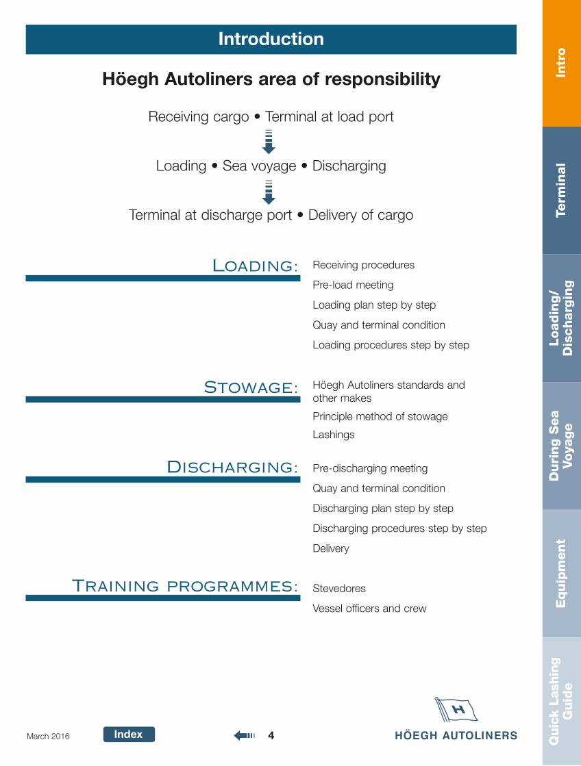
Höegh Autoliners area of responsibility
Receiving cargo • Terminal at load port
Loading • Sea voyage • Discharging
Terminal at discharge port • Delivery of cargo
Loading:
Stowage:
Discharging:
Training programmes:
Receiving procedures
Pre-load meeting
Loading plan step by step
Quay and terminal condition
Loading procedures step by step
Höegh Autoliners standards and other makes
Principle method of stowage
Lashings
Pre-discharging meeting
Quay and terminal condition
Discharging plan step by step
Discharging procedures step by step
Delivery
Stevedores
Vessel officers and crew
Term
inal
Intr
oLoadin
g/
Dis
charg
ing
Duri
ng S
ea
Voya
ge
Equip
ment
Quic
k La
shin
gG
uid
e
Index 5March 2016
Terminal Index
Page
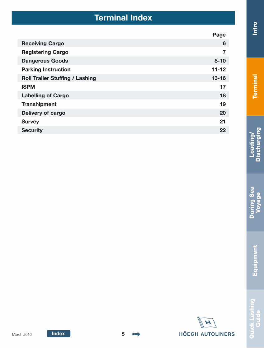
Receiving Cargo 6
Registering Cargo 7
Dangerous Goods 8-10
Parking Instruction 11-12
Roll Trailer Stuffing / Lashing 13-16
ISPM 17
Labelling of Cargo 18
Transhipment 19
Delivery of cargo 20
Survey 21
Security 22
Term
inal
Intr
oLoadin
g/
Dis
charg
ing
Duri
ng S
ea
Voya
ge
Equip
ment
Quic
k La
shin
gG
uid
e
Index 6March 2016
Receiving Cargo
• Höegh Autoliners will accept only cargo that comply to all international treaties related to sea transportation established byIMO and countries/areas related and that can be safely handled,loaded, stowed, transported and discharged from the vessels underour control without endanger the safety of shore personnel, crew,environment or vessel, and is complying with Höegh Autoliners"Cargo Acceptance Policy"
• All cargo must fulfill local regulations and custom requirements for export. All cargo is subject to security search.
• All cargo must have a valid booking issued by Höegh Autoliners.
• All cargo must have accompanying Shipping Note (a.k.a. Dock receipt).
• All cargo must be clean (free of accumulated materials), with no leaking fluids.
• All cargo must be equipped with adequate, clearly marked and easily accessible lashing points. All moveable parts must be secured manually.
• All self-propelled units must have sufficient fuel for Ro/Ro load/discharge but not more than one-fourth (25%) of tank volume.
• All drivable units must be furnished with operation key, or key card, or code, or similar functional substitute.
• Höegh Autoliners local booking office to be called if cargo is not upto local stevedoring or Höegh Autoliners stan-dards (mechanically,safety, security, including flat tires).
Term
inal
Intr
oLoadin
g/
Dis
charg
ing
Duri
ng S
ea
Voya
ge
Equip
ment
Quic
k La
shin
gG
uid
e
Index 7March 2016
Registering Cargo
Check that deliverer has a “Dock Receipt” with all relevant information.Check following on cargo unit and dock receipt1. Unit VIN / Chassis number (to be verified for accuracy) 2. Consignee name / address & notify name / address3. Booking number and vessel /voyage number4. Cargo units dimensions and weight check, and registered
according to Höegh Autoliners Measuring Procedure.5. Cargo unit to be visually checked for major damages and
missing items. Höegh Autoliners local office to be contactedif major damages, flat tires, mechanical deficient are notedthat are not fulfilling Höegh Cargo Acceptance requirements.
6. Proper documents for Dangerous Goods, if applicable.7. Proper ISPM documentation, if applicable8. Cargo to be security searched according to ISPS rules9. Static cargo should have the following clearly marked:
• Gross weight• Centre of gravity• Forklift points (Cargo or package design is to be
suitable for safe forklift handling without risking damage.)
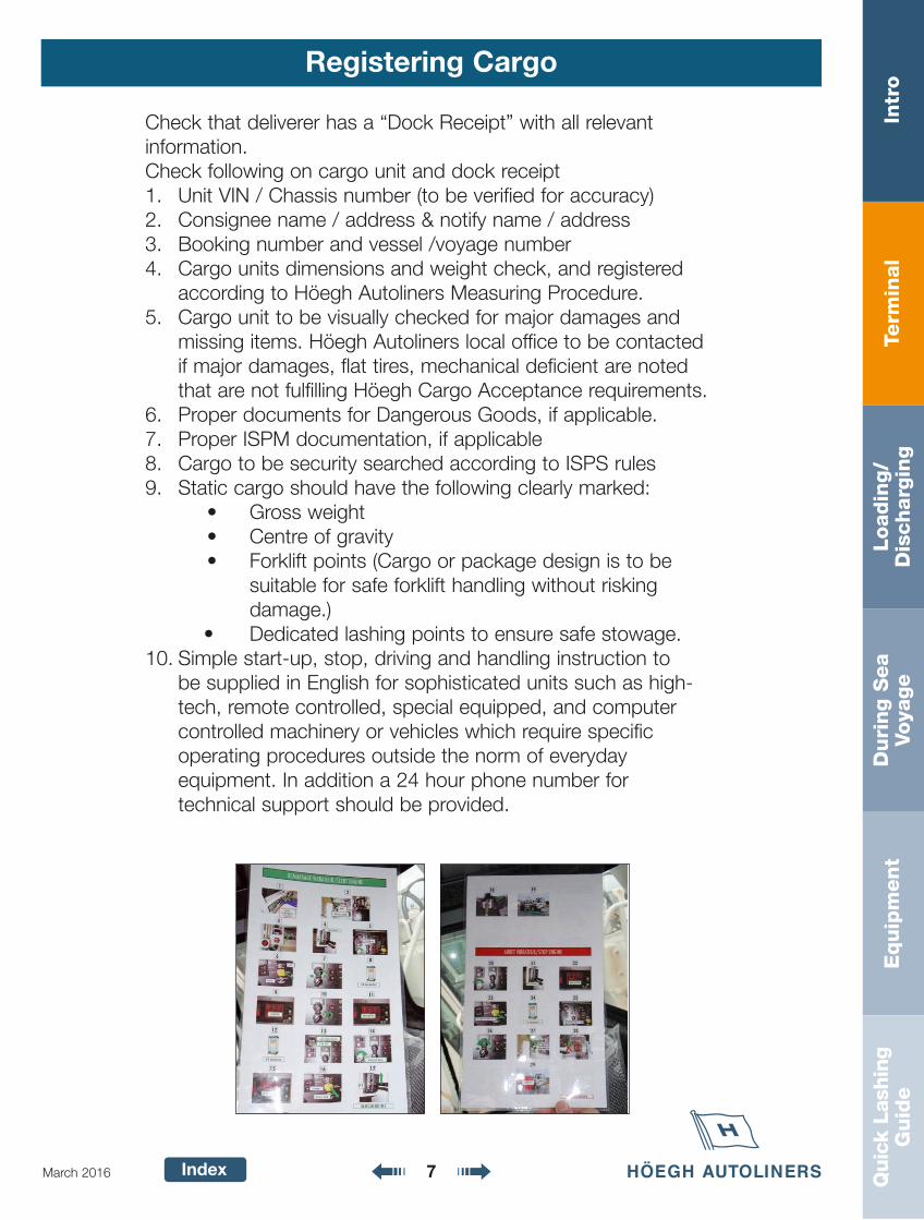
• Dedicated lashing points to ensure safe stowage. 10. Simple start-up, stop, driving and handling instruction to
be supplied in English for sophisticated units such as high-tech, remote controlled, special equipped, and computercontrolled machinery or vehicles which require specific operating procedures outside the norm of everyday equipment. In addition a 24 hour phone number for technical support should be provided.
Term
inal
Intr
oLoadin
g/
Dis
charg
ing
Duri
ng S
ea
Voya
ge
Equip
ment
Quic
k La
shin
gG
uid
e
Index 8March 2016
Dangerous Goods
Acceptance of Dangerous Goods and Empty Tanks
• Dangerous and polluting cargo is only to be booked uponreceiving acceptance from [email protected] ([email protected] for U.S. flagged vessels).
• Dangerous Goods Acceptance Form to be issued by IMDG department in Oslo.
• Before loading IMO manifest and copy of DGDDeclaration to be delivered to Vessel's Master, [email protected] ([email protected] for U.S. Flagged Vessels).
• Vessel crew and Höegh Autoliners Port Captain has theright to refuse any cargo not properly marked/certified or registered.
Gas Free Certificate Requirements
• Portable tanks and road tank vehicles, regardless of previous content, must be accompanied with a certificatestating that the tank has been cleaned and gas-freed,presented before loading.
• NB! Empty tanks, not cleaned and not gas-freed mustcomply with the same requirements as tanks filled withthe previous substance.
• Factory new tanks need to be accompanied by a state-ment from OEM/shipper that the tank is new and has notbeen exposed to any dangerous substances and there-fore declared gas-free
• The agent must deliver a copy of the gas free certificateto Vessel’s Master before loading.
• Vessel crew and Höegh Autoliners Port Captain have theright to refuse cargo if gas free certificate is not provided
Term
inal
Intr
oLoadin
g/
Dis
charg
ing
Duri
ng S
ea
Voya
ge
Equip
ment
Quic
k La
shin
gG
uid
e
Index 9March 2016
Dangerous Goods
" D D a a n n g e r r o u u s g o o o d s s " " a c c c c e p t a n n c c e e f o r m : D O P : L O P : o n e g a y o V : l e s s e V
: o n g n i k o o B : ) y n a f i ( k s i r b u S : s s a l C O M I : r e b m u n N U
: e m a n g n i p p i h s r e p o r P
: o g r a c s i h t r o f s t n e m e r i u q e r l a i c e p S
? s s a l C O M I s i h t f o o g r a c g n i y r r a c r o f d e i f i t r e c l e s s e v e h t e r A
? e g a w o t s k c e d r e d n u r o f e l b a t i u s o g r a c O M I e h t e r A
? e g a y o v e m a s e h t n o d e i r r a c e b o t d e d n e t n i s e s s a l c r e h t o f o o g r a c O M I e r A . d e d a o l e b o t s r e b m u n N U e h t l l a r o f w o l e b e l b a t e h t e t e l p m o c , s e Y f I
s s a l C r e b m u n N U " m o r f y a w A "
: s s a l c " m o r f d e t a r a p e S "
: s s a l c
a y b d e t a r a p e S " e t e l p m o c
r o t n e m t r a p m o c : s s a l c " m o r f d l o h
d e t a r a p e S " y b y l l a n i d u t i g n o l
g n i n e v r e t n i n a e t e l p m o c
r o t n e m t r a p m o c : s s a l c " m o r f d l o h
l a u t c a t o N = X : e t o N
: e t a D : n i a t p a C t r o P y b d e t e l p m o C
2 0 . 2 1 . 1 0 : e t a d n o i s i v e R - 0 . 1 : . o N n o i s i v e R - F 3 1 - P - G R A C : . o N m r o F
e S g e r g s t n e m e r i u q e r n o i t a
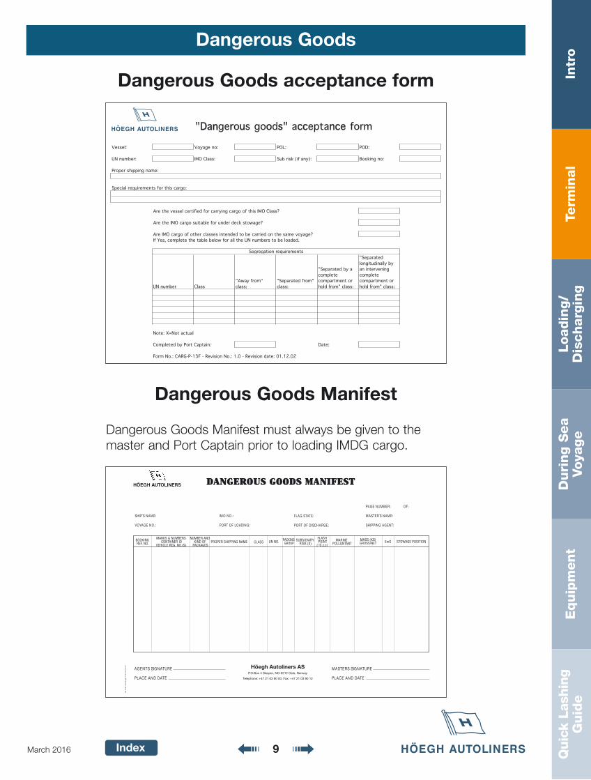
Dangerous Goods acceptance form
Dangerous Goods Manifest
Dangerous Goods Manifest must always be given to themaster and Port Captain prior to loading IMDG cargo.
:EMAN S´PIHS
:.ON EGAYOV
:.ON OMI
:GNIDAOL FO TROP
:ETATS GALF
:EGRAHCSID FO TROP
:FO :REBMUN EGAP
:EMAN S´RETSAM
:TNEGA GNIPPIHS
G N I K O O B . O N . F E R
S R E B M U N & S K R A M D I R E N I A T N O C
) S ( . O N . G E R E L C I H E V
D N A R E B M U N F O D N I K
S E G A K C A P E M A N G N I P P I H S R E P O R P S S A L C . O N N U G N I K C A P
P U O R G Y R A I D I S B U S
) S ( K S I R
H S A L F T N I O P ) c . c . C º (
E N I R A M T N A T N U L L O P
) G K ( S S A M T E N / S S O R G N O I T I S O P E G A W O T S S m E
ERUTANGIS STNEGA
ETAD DNA ECALP
ERUTANGIS SRETSAM
ETAD DNA ECALP
S A s r e n i l o t u A h g e ö H y a w r o N , o l s O 2 1 2 0 - O N , n e y ø k S 4 x o B . O . P
2 1 0 9 3 0 1 2 7 4 + : x a F , 0 0 0 9 3 0 1 2 7 4 + : e n o h p e l e T
Bl.
45
87
Gra
fotr
ykk
tlf. 6
3 8
6 3
9 2
0
SRENILOTUA HGEÖH
Term
inal
Intr
oLoadin
g/
Dis
charg
ing
Duri
ng S
ea
Voya
ge
Equip
ment
Quic
k La
shin
gG
uid
e
Index 10March 2016
Dangerous Goods
Gas free certificate
2
FLAMMABLEGAS
2
NON FLAMMABLECOMPRESSED GAS
2
TOXIC GAS
*** 2)
1
1.4
EXPLOSIVES
3
FLAMMABLELIQUID
Flammable solid
4 4
SPONTANEOUSLYCOMBUSTIBLE
4
DANGEROUSWHEN WET
5.1
OXIDIZING AGENT CORROSIVE
86
TOXIC
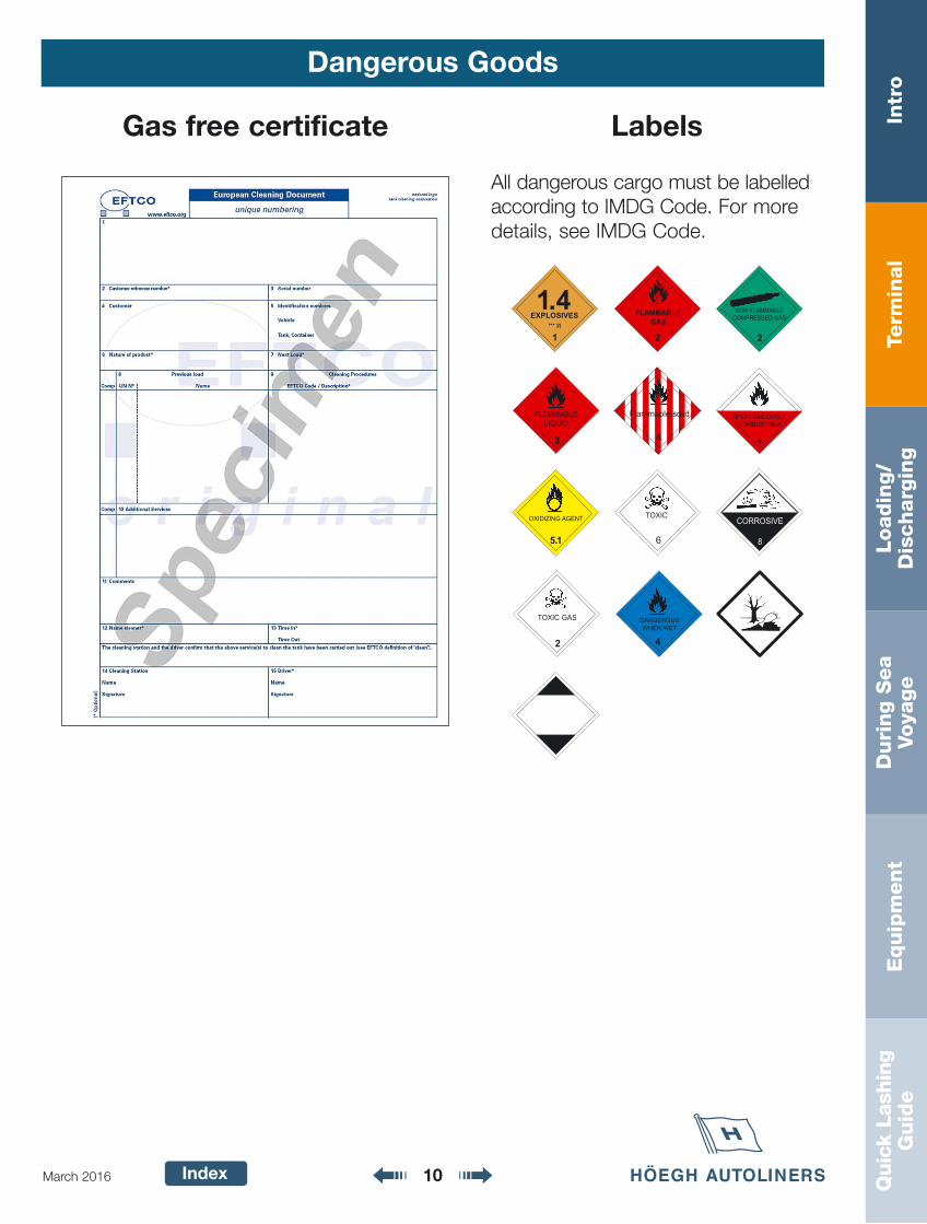
Labels
All dangerous cargo must be labelledaccording to IMDG Code. For moredetails, see IMDG Code.
Term
inal
Intr
oLoadin
g/
Dis
charg
ing
Duri
ng S
ea
Voya
ge
Equip
ment
Quic
k La
shin
gG
uid
e
Index 11March 2016
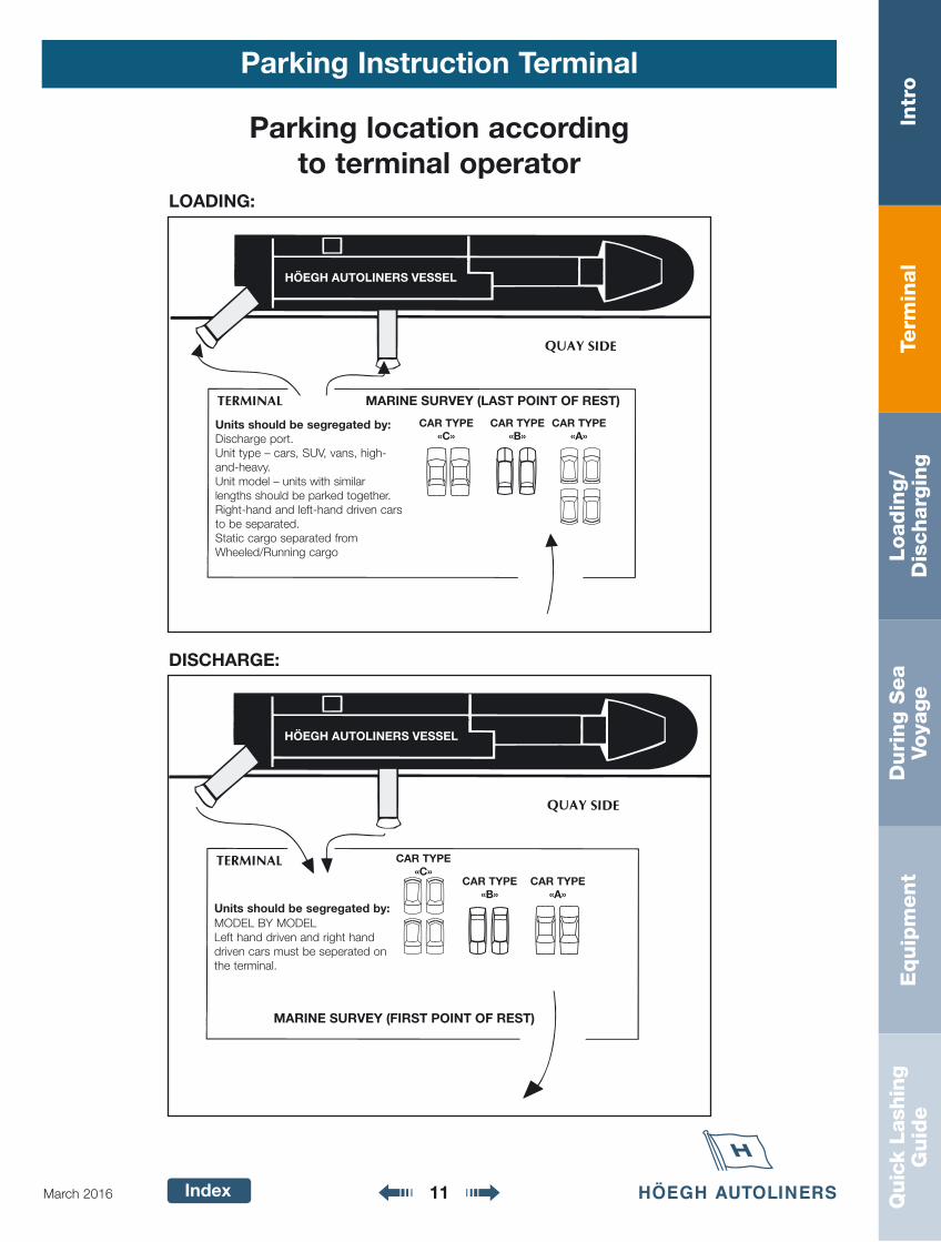
Parking Instruction Terminal
Parking location according to terminal operator
MARINE SURVEY (LAST POINT OF REST)
Units should be segregated by:Discharge port.Unit type – cars, SUV, vans, high-and-heavy.Unit model – units with similar lengths should be parked together.Right-hand and left-hand driven carsto be separated.Static cargo separated fromWheeled/Running cargo
CAR TYPE«B»
CAR TYPE«A»
CAR TYPE«C»
MARINE SURVEY (FIRST POINT OF REST)
Units should be segregated by:MODEL BY MODELLeft hand driven and right handdriven cars must be seperated onthe terminal.
CAR TYPE«C»
CAR TYPE«B»
CAR TYPE«A»
LOADING:
DISCHARGE:
Term
inal
Intr
oLoadin
g/
Dis
charg
ing
Duri
ng S
ea
Voya
ge
Equip
ment
Quic
k La
shin
gG
uid
e
Index 12March 2016
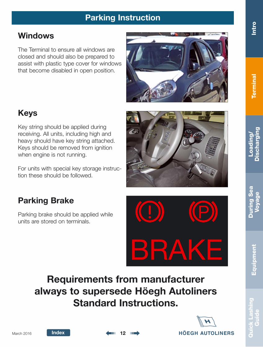
Parking Instruction
Windows
The Terminal to ensure all windows areclosed and should also be prepared toassist with plastic type cover for windowsthat become disabled in open position.
Keys
Key string should be applied during receiving. All units, including high andheavy should have key string attached.Keys should be removed from ignitionwhen engine is not running.
For units with special key storage instruc-tion these should be followed.
Parking Brake
Parking brake should be applied whileunits are stored on terminals.
BRAKE
P
Requirements from manufacturer always to supersede Höegh Autoliners
Standard Instructions.
Term
inal
Intr
oLoadin
g/
Dis
charg
ing
Duri
ng S
ea
Voya
ge
Equip
ment
Quic
k La
shin
gG
uid
e
Index 13March 2016
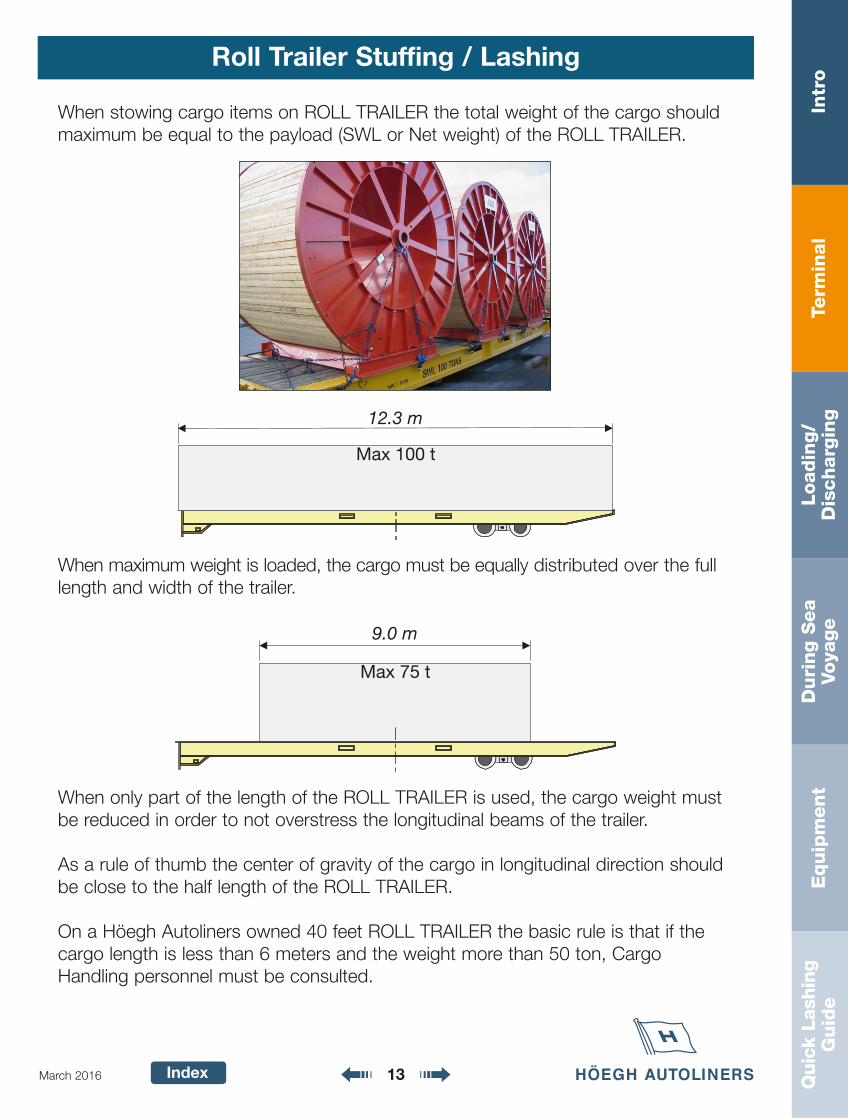
Roll Trailer Stuffing / Lashing
When stowing cargo items on ROLL TRAILER the total weight of the cargo shouldmaximum be equal to the payload (SWL or Net weight) of the ROLL TRAILER.
Max 100 t
12.3 m
When maximum weight is loaded, the cargo must be equally distributed over the fulllength and width of the trailer.
When only part of the length of the ROLL TRAILER is used, the cargo weight mustbe reduced in order to not overstress the longitudinal beams of the trailer.
As a rule of thumb the center of gravity of the cargo in longitudinal direction shouldbe close to the half length of the ROLL TRAILER.
On a Höegh Autoliners owned 40 feet ROLL TRAILER the basic rule is that if thecargo length is less than 6 meters and the weight more than 50 ton, CargoHandling personnel must be consulted.
Max 75 t
9.0 m
Term
inal
Intr
oLoadin
g/
Dis
charg
ing
Duri
ng S
ea
Voya
ge
Equip
ment
Quic
k La
shin
gG
uid
e
Index 14March 2016
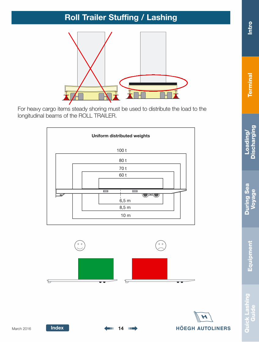
Roll Trailer Stuffing / Lashing
Uniform distributed weights
100 t
80 t
70 t
60 t
6,5 m
8,5 m
10 m
For heavy cargo items steady shoring must be used to distribute the load to the longitudinal beams of the ROLL TRAILER.
Term
inal
Intr
oLoadin
g/
Dis
charg
ing
Duri
ng S
ea
Voya
ge
Equip
ment
Quic
k La
shin
gG
uid
e
Index 15March 2016
Roll Trailer Stuffing / Lashing
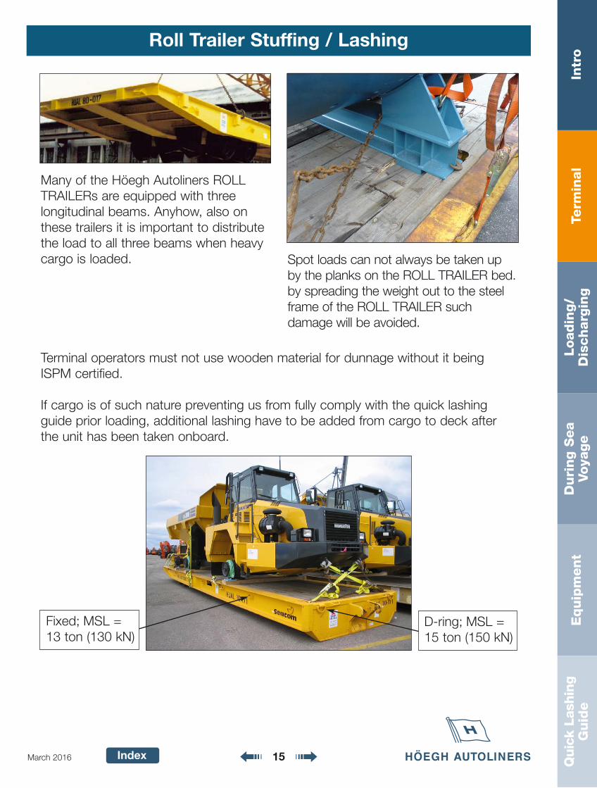
Many of the Höegh Autoliners ROLLTRAILERs are equipped with three longitudinal beams. Anyhow, also onthese trailers it is important to distributethe load to all three beams when heavycargo is loaded. Spot loads can not always be taken up
by the planks on the ROLL TRAILER bed.by spreading the weight out to the steelframe of the ROLL TRAILER such damage will be avoided.
Terminal operators must not use wooden material for dunnage without it beingISPM certified.
If cargo is of such nature preventing us from fully comply with the quick lashingguide prior loading, additional lashing have to be added from cargo to deck afterthe unit has been taken onboard.
D-ring; MSL =15 ton (150 kN)
Fixed; MSL =13 ton (130 kN)
Term
inal
Intr
oLoadin
g/
Dis
charg
ing
Duri
ng S
ea
Voya
ge
Equip
ment
Quic
k La
shin
gG
uid
e
Index 16March 2016
Roll Trailer Stuffing / Lashing
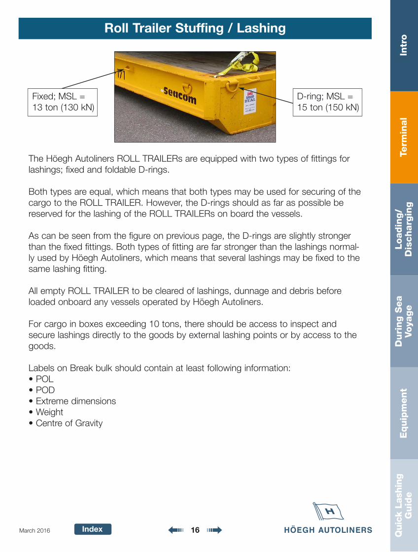
The Höegh Autoliners ROLL TRAILERs are equipped with two types of fittings forlashings; fixed and foldable D-rings.
Both types are equal, which means that both types may be used for securing of thecargo to the ROLL TRAILER. However, the D-rings should as far as possible bereserved for the lashing of the ROLL TRAILERs on board the vessels.
As can be seen from the figure on previous page, the D-rings are slightly strongerthan the fixed fittings. Both types of fitting are far stronger than the lashings normal-ly used by Höegh Autoliners, which means that several lashings may be fixed to thesame lashing fitting.
All empty ROLL TRAILER to be cleared of lashings, dunnage and debris beforeloaded onboard any vessels operated by Höegh Autoliners.
For cargo in boxes exceeding 10 tons, there should be access to inspect andsecure lashings directly to the goods by external lashing points or by access to thegoods.
Labels on Break bulk should contain at least following information:• POL• POD• Extreme dimensions • Weight• Centre of Gravity
Fixed; MSL =13 ton (130 kN)
D-ring; MSL =15 ton (150 kN)
Term
inal
Intr
oLoadin
g/
Dis
charg
ing
Duri
ng S
ea
Voya
ge
Equip
ment
Quic
k La
shin
gG
uid
e
Index 17March 2016
ISPM
International Standards for PhytosanitaryMeasure or Invasive Species and
Pest Management
The regulation indicate that:
1. All wood packaging material with a thickness of more than 5 mm,including dunnage, must be manufactured and treated in thecountry of origin as follows:
Heat Treatment (HT). Wood packaging material should beheated in accordance with specific time/temperature schedule that achieves a minimum wood core temperature of plus 56 degrees Celsius for a minimum of 30 minutes. Kiln-drying (KD) and Chemical Pressure Impregnation (CPI),may be considered HT treatments to the extent that thesemeet HT specifications.Methyl bromide (MB) fumigation for wood packaging material.The wood packaging material should be fumigated withMethyl bromide. There are various standards to dosage/temperature etc.
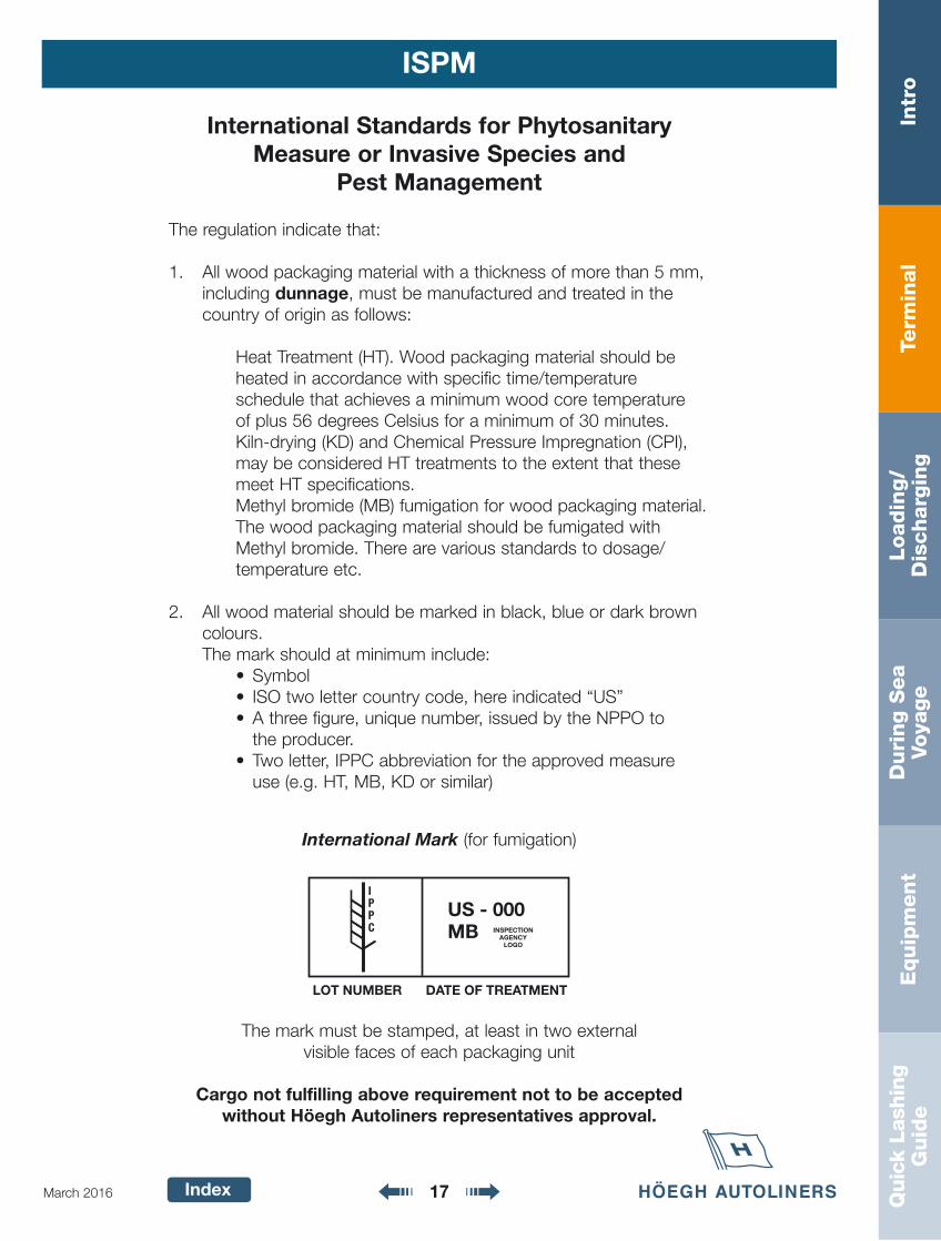
2. All wood material should be marked in black, blue or dark browncolours.The mark should at minimum include:
• Symbol• ISO two letter country code, here indicated “US”• A three figure, unique number, issued by the NPPO to
the producer.• Two letter, IPPC abbreviation for the approved measure
use (e.g. HT, MB, KD or similar)
International Mark (for fumigation)
The mark must be stamped, at least in two external visible faces of each packaging unit
Cargo not fulfilling above requirement not to be accepted without Höegh Autoliners representatives approval.
US - 000MB INSPECTION
AGENCYLOGO
LOT NUMBER DATE OF TREATMENT
IPPC
Term
inal
Intr
oLoadin
g/
Dis
charg
ing
Duri
ng S
ea
Voya
ge
Equip
ment
Quic
k La
shin
gG
uid
e
Index 18March 2016
Labelling of Cargo
Höegh Autoliners have developed two types of cargo labelsto indicate discharge ports:
• Port hangers: To be used on all vehicles, where it ispractically possible to use them. (Exception: Where manufacturer has denied Höegh Autoliners to use them)
• Port stickers: To be used on cargo where it is not practical to use “port hangers”.
Where bar code labels are used, the main part is to beplaced on the left rear window in the upper left corner.
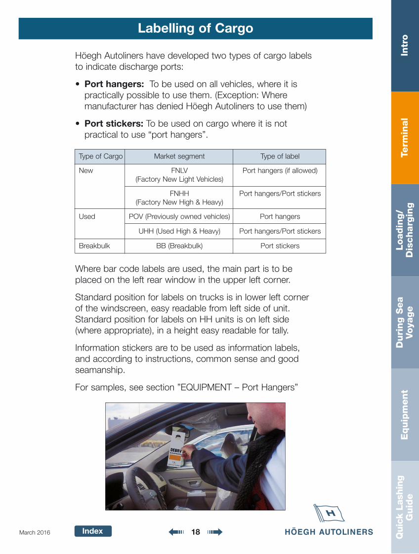
Standard position for labels on trucks is in lower left cornerof the windscreen, easy readable from left side of unit.Standard position for labels on HH units is on left side(where appropriate), in a height easy readable for tally.
Information stickers are to be used as information labels,and according to instructions, common sense and goodseamanship.
For samples, see section ”EQUIPMENT – Port Hangers”
Type of Cargo Market segment Type of label
New FNLV Port hangers (if allowed)(Factory New Light Vehicles)
FNHH Port hangers/Port stickers(Factory New High & Heavy)
Used POV (Previously owned vehicles) Port hangers
UHH (Used High & Heavy) Port hangers/Port stickers
Breakbulk BB (Breakbulk) Port stickers
Term
inal
Intr
oLoadin
g/
Dis
charg
ing
Duri
ng S
ea
Voya
ge
Equip
ment
Quic
k La
shin
gG
uid
e
Index 19March 2016
Transhipment
Requirements
When handling Höegh Autoliners transshipment cargo, ThisManual shall apply. Manufactures standard may exceed HöeghAutoliners standard and must be followed.
Terminal Storage
Distances between cars are according to this manual.Cars shall be locked and keys safely been taken care of by theTerminal Operator.Remember -- turn off the radio -- close all windows.The cars should be placed together and stowed model by model and separated Port by Port. When cars are placed at the terminal, guards should be placed there 24 hours a day.
Stowage
When loading or discharging Höegh Autoliners transshipmentcargo, Höegh Autoliners cargo handling quality as stated in ourmanual shall apply.
Term
inal
Intr
oLoadin
g/
Dis
charg
ing
Duri
ng S
ea
Voya
ge
Equip
ment
Quic
k La
shin
gG
uid
e
Index
Delivery of cargo
20March 2016
Delivery against Bill of Lading
Agents at discharge ports are only to give delivery orderagainst original B/L. Deviation from such routine can only beauthorized in writing by Höegh Autoliners Oslo.
For direct/straight consignment Bills of Lading (i.e. ships tonamed consignee), cargo can be released against properidentification, provided a no objection is given by shippers.
Höegh Autoliners Bill of Lading

Term
inal
Intr
oLoadin
g/
Dis
charg
ing
Duri
ng S
ea
Voya
ge
Equip
ment
Quic
k La
shin
gG
uid
e
Index 21March 2016
Survey
Preload/Discharge survey
Cargo should be surveyed upon request from HöeghAutoliners Oslo/Höegh Autoliners NA.
Levels of survey:Level 1 – Check list inspectionLevel 2 – Standard or commercial inspectionLevel 3 – Quality in-depth inspection
As a general rule the preload/discharge survey will be conducted at last/first point of rest.
Survey personnel to use following dresscode:
1: Use correct personal protective wear. Not exposing buttons, zippers etc.
2: No sharp objects such as knifes, rings, wristwatches orsimilar to be used whilst surveying Höegh Autolinerscargo.
Survey of Höegh Autoliners cargo only to be done duringdaylight condition when possible.
Term
inal
Intr
oLoadin
g/
Dis
charg
ing
Duri
ng S
ea
Voya
ge
Equip
ment
Quic
k La
shin
gG
uid
e
Index
Security
22March 2016
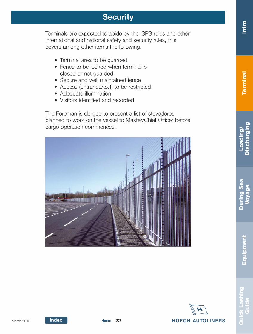
Terminals are expected to abide by the ISPS rules and otherinternational and national safety and security rules, this covers among other items the following.
• Terminal area to be guarded• Fence to be locked when terminal is
closed or not guarded• Secure and well maintained fence• Access (entrance/exit) to be restricted• Adequate illumination• Visitors identified and recorded
The Foreman is obliged to present a list of stevedoresplanned to work on the vessel to Master/Chief Officer beforecargo operation commences.
Loadin
g/
Dis
charg
ing
Intr
oTe
rmin
al
Duri
ng S
ea
Voya
ge
Equip
ment
Quic
k La
shin
gG
uid
e
Index 23March 2016
Loading/Discharging Index
Page
Höegh Autoliners Standard Instructions 24-25
Safety 26
Stowplan 27
Axle Load and Uniform Load 28
Deck Arrangement 29
Pre-Loading/Discharging Meeting 30
Pre-Loading/Discharging Meeting On Board 31-32
Cargo Holds 33
Ramps and Driveways 34-36
Dresscode 37
Vessels Routines 38
Crew Members Duties 38-39
Ventilation of Cargo Holds 40
Ramp Meeting 41
Unlashing 42
Höegh Autoliners Stowage Standard 43-45
Entering/Leaving Cars 46
Driving to/from Vessel 46
Tally 47-48
Höegh Autoliners Lashing Standard 49
Securing of Cars and Light Cargo 0 - 3000 kg 50-51
Höegh Autoliners Stowage Standard - High and Heavy 52
Securing of High and Heavy 3000 - 10000 kg on rubber tyres 53-54
Chassis 55
Securing of High and Heavy 10000 kg to 120000 kg on rubber tyres 56-57
Securing with heavy heavy duty weblash 120000 - 200000 kg 58
Securing of Static, Roll trailer, Excavators and other H/H not on rubber tyres 59-69
Used or Damaged Units 70-71
Clean Cargo 71
Short Sea/Feeder 72
Loadin
g/
Dis
charg
ing
Intr
oTe
rmin
al
Duri
ng S
ea
Voya
ge
Equip
ment
Quic
k La
shin
gG
uid
e
Index 24March 2016
Höegh Autoliners Standard Instructions
General
1. Load/discharge plan and procedures will be supplied by Höegh Autoliners or HöeghAutoliners representative. All cargo operations shall be according to the agreed stow plan.Alterations, if any, may only be made if cleared by Höegh Autoliners Port Captain or vessel’sMaster.
2. Due diligence to safety should be given at all times during cargo operation.
3. Personnel must be skilled, experienced and trained according to actual Höegh Autolinerscargo handling instructions. Training sessions should be arranged at least every six months(update on operating new models etc.). For drivers a valid driver’s licence is compulsory.
4. A careful supervision by the crew during loading and discharging operation is of great importance. The crew should ensure that Höegh Cargo Quality Manual requirements are followed.
5. The Master is the ultimately responsible for the safety of the vessel and that the cargo onboard is secured in accordance with the vessel specific Cargo Securing Manual. The lashingof all cargo on board must be carried out to the satisfaction of the ship’s command.
Cargo Operation
The following points are intended as guidelines to be followed by all Höegh Autoliners ServiceCompany employees while loading or discharging Höegh Autoliners controlled vessels and allother Höegh Autoliners controlled cargo.
These points are not to be considered a full and complete description of how to load and dis-charge from a total method instruction standpoint, nor do they fully describe work routinesfrom a safety or workmanlike point of view. These remain the responsibility of the HöeghAutoliners appointed Service Company, however, the points outlined here do describe the stepsrecommended by Höegh Autoliners as fundamentals of quality cargo handling.
1. It is strictly forbidden to use Höegh Autoliners cargo in any way as transport or in assistingother cargo in being loaded/discharged.
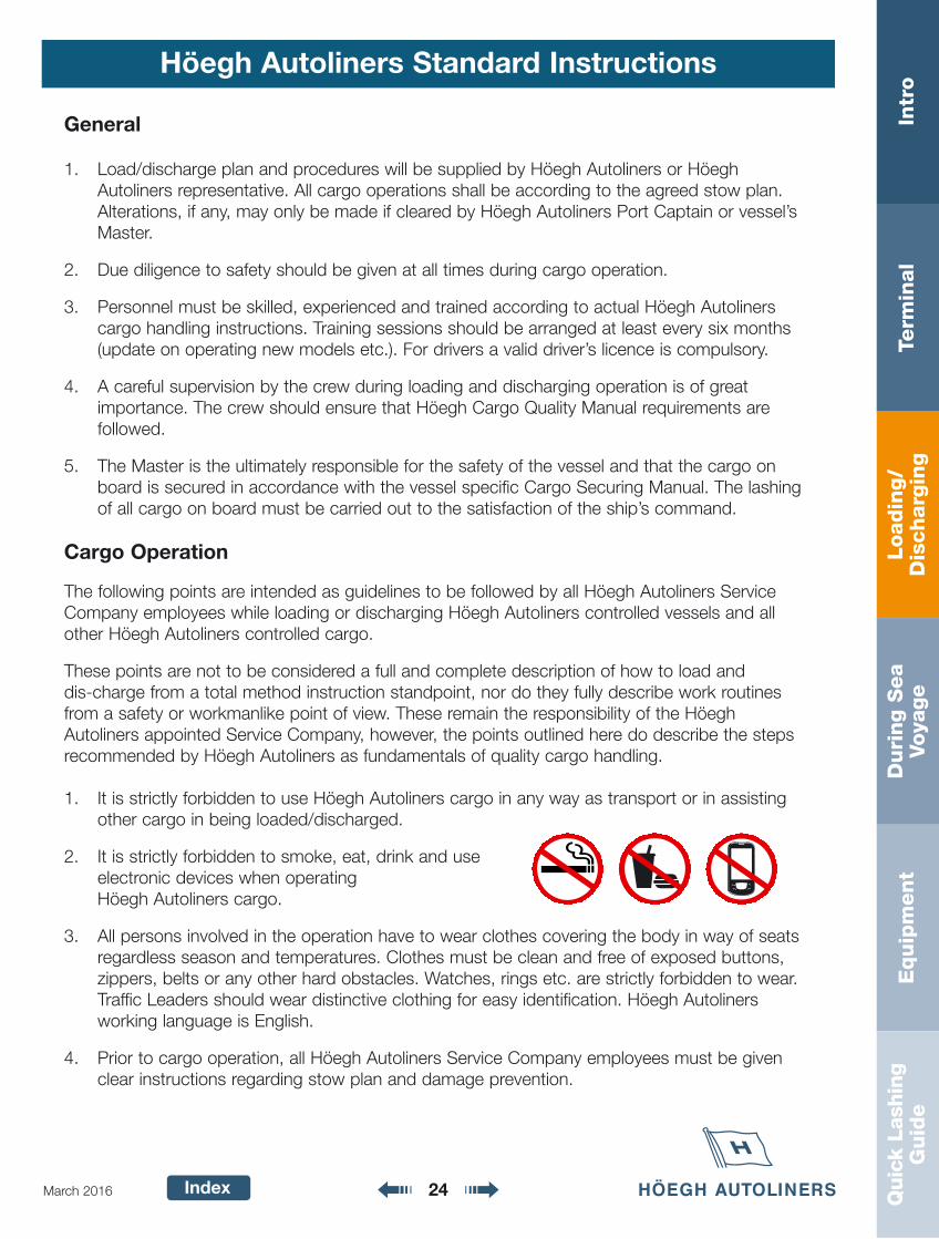
2. It is strictly forbidden to smoke, eat, drink and use electronic devices when operatingHöegh Autoliners cargo.
3. All persons involved in the operation have to wear clothes covering the body in way of seatsregardless season and temperatures. Clothes must be clean and free of exposed buttons,zippers, belts or any other hard obstacles. Watches, rings etc. are strictly forbidden to wear.Traffic Leaders should wear distinctive clothing for easy identification. Höegh Autoliners working language is English.
4. Prior to cargo operation, all Höegh Autoliners Service Company employees must be givenclear instructions regarding stow plan and damage prevention.
Loadin
g/
Dis
charg
ing
Intr
oTe
rmin
al
Duri
ng S
ea
Voya
ge
Equip
ment
Quic
k La
shin
gG
uid
e
Index 25March 2016
Höegh Autoliners Standard Instructions
5. Foreman/Supervisor/Traffic Leaders must be part of each gang and placed in blind areas toguide units in and out of stowed position. Longshoremen/stevedores, inspecting personnel,and lashers should never touch painted surfaces. Furthermore personnel should not sit, leanor rest on or against vehicles, not eat or drink and not smoke in or around vehicles.
6. All drivers must enter/leave the unit via drivers door.
7. All self propelled units loaded on board Höegh Autoliners operated vessels must be in goodworking condition and safe to handle. The vehicle should be provided with sufficient fuel, butnot more than one-quarter of a tank. All units must fulfill Höegh Autoliners cargo acceptancepolicy.
8. During cargo operation, brakes must be tested before entering the vessels ramp. Keep sufficient distance and always use headlights when driving inside the vessel.
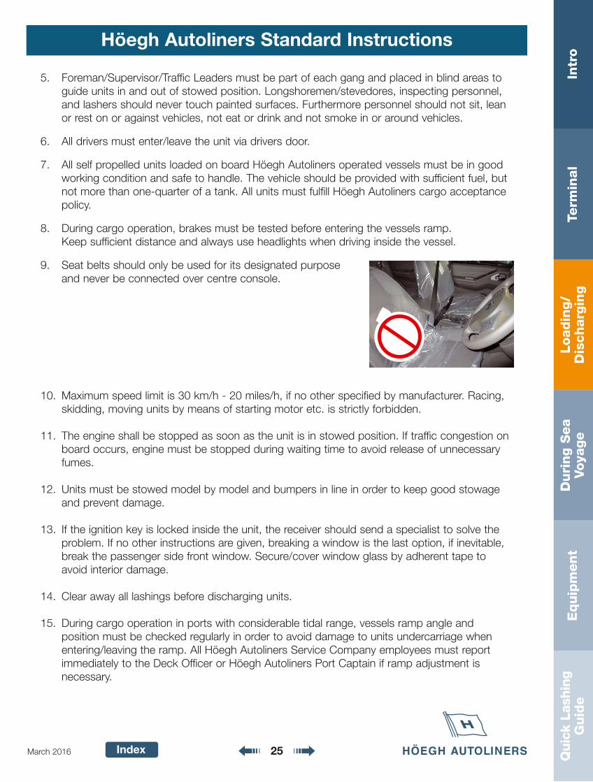
9. Seat belts should only be used for its designated purpose and never be connected over centre console.
10. Maximum speed limit is 30 km/h - 20 miles/h, if no other specified by manufacturer. Racing,skidding, moving units by means of starting motor etc. is strictly forbidden.
11. The engine shall be stopped as soon as the unit is in stowed position. If traffic congestion onboard occurs, engine must be stopped during waiting time to avoid release of unnecessaryfumes.
12. Units must be stowed model by model and bumpers in line in order to keep good stowageand prevent damage.
13. If the ignition key is locked inside the unit, the receiver should send a specialist to solve theproblem. If no other instructions are given, breaking a window is the last option, if inevitable,break the passenger side front window. Secure/cover window glass by adherent tape toavoid interior damage.
14. Clear away all lashings before discharging units.
15. During cargo operation in ports with considerable tidal range, vessels ramp angle and position must be checked regularly in order to avoid damage to units undercarriage whenentering/leaving the ramp. All Höegh Autoliners Service Company employees must reportimmediately to the Deck Officer or Höegh Autoliners Port Captain if ramp adjustment is necessary.
Loadin
g/
Dis
charg
ing
Intr
oTe
rmin
al
Duri
ng S
ea
Voya
ge
Equip
ment
Quic
k La
shin
gG
uid
e
Index 26March 2016
Safety
The Master/Chief Officer must make sure that alldanger areas and exposed areas at all times areclearly marked or fenced off.
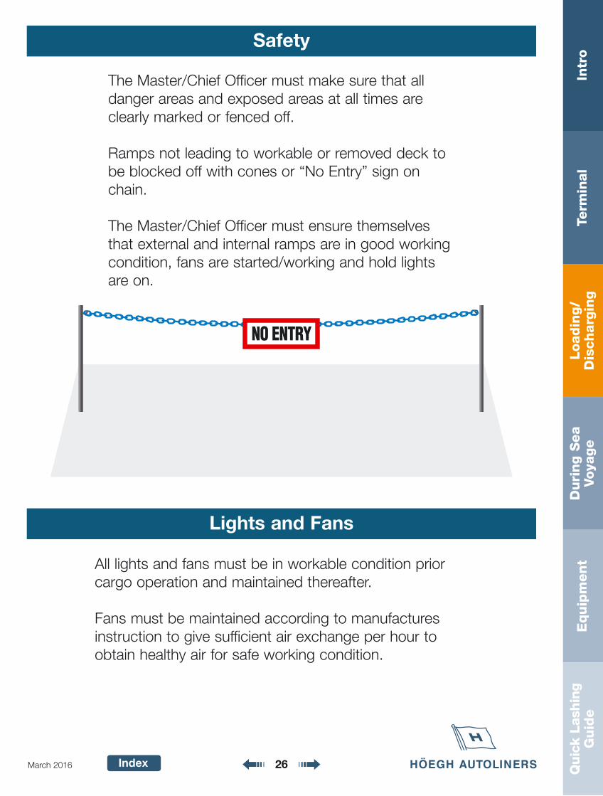
Ramps not leading to workable or removed deck tobe blocked off with cones or “No Entry” sign onchain.
The Master/Chief Officer must ensure themselvesthat external and internal ramps are in good workingcondition, fans are started/working and hold lightsare on.
Lights and Fans
All lights and fans must be in workable condition priorcargo operation and maintained thereafter.
Fans must be maintained according to manufacturesinstruction to give sufficient air exchange per hour toobtain healthy air for safe working condition.
Loadin
g/
Dis
charg
ing
Intr
oTe
rmin
al
Duri
ng S
ea
Voya
ge
Equip
ment
Quic
k La
shin
gG
uid
e
Index 27March 2016
Stowplan
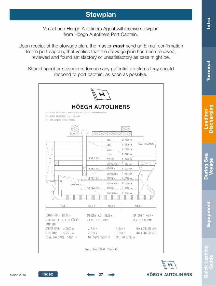
Vessel and Höegh Autoliners Agent will receive stowplan from Höegh Autoliners Port Captain.
Upon receipt of the stowage plan, the master must send an E-mail confirmation to the port captain, that verifies that the stowage plan has been received,
reviewed and found satisfactory or unsatisfactory as case might be.
Should agent or stevedores foresee any potential problems they should respond to port captain, as soon as possible.
Loadin
g/
Dis
charg
ing
Intr
oTe
rmin
al
Duri
ng S
ea
Voya
ge
Equip
ment
Quic
k La
shin
gG
uid
e
Index 28March 2016
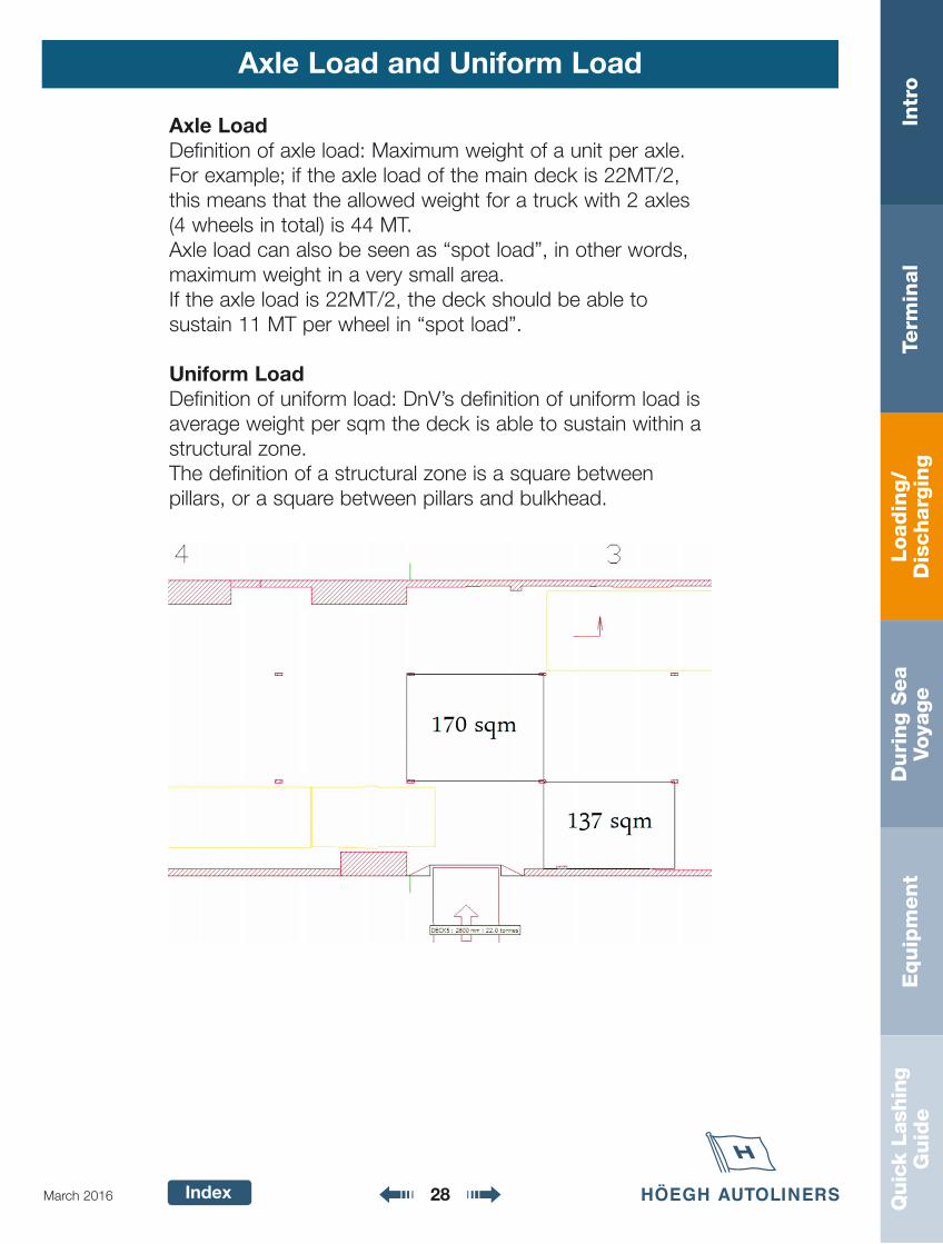
Axle Load and Uniform Load
Axle LoadDefinition of axle load: Maximum weight of a unit per axle.For example; if the axle load of the main deck is 22MT/2,this means that the allowed weight for a truck with 2 axles(4 wheels in total) is 44 MT.Axle load can also be seen as “spot load”, in other words,maximum weight in a very small area.If the axle load is 22MT/2, the deck should be able to sustain 11 MT per wheel in “spot load”.
Uniform LoadDefinition of uniform load: DnV’s definition of uniform load isaverage weight per sqm the deck is able to sustain within astructural zone.The definition of a structural zone is a square between pillars, or a square between pillars and bulkhead.
Loadin
g/
Dis
charg
ing
Intr
oTe
rmin
al
Duri
ng S
ea
Voya
ge
Equip
ment
Quic
k La
shin
gG
uid
e
Index 29March 2016
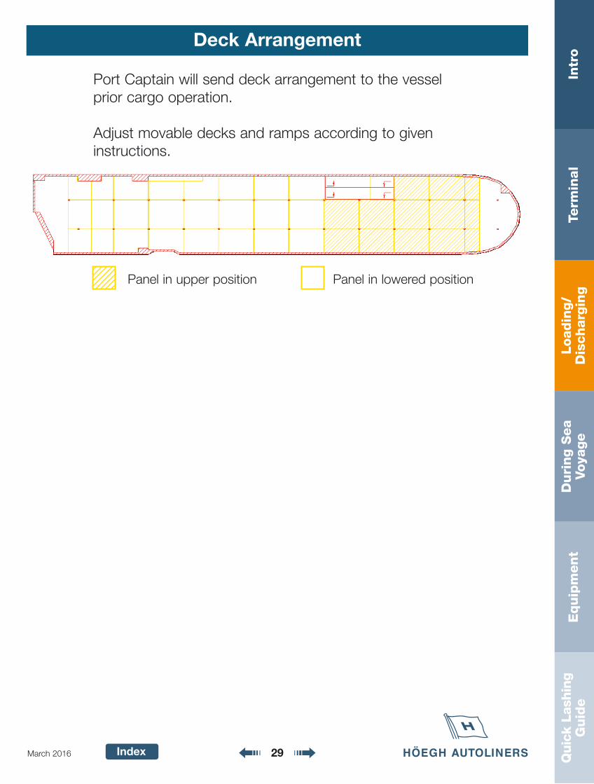
Deck Arrangement
Panel in upper position Panel in lowered position
Port Captain will send deck arrangement to the vesselprior cargo operation.
Adjust movable decks and ramps according to giveninstructions.

Loadin
g/
Dis
charg
ing
Intr
oTe
rmin
al
Duri
ng S
ea
Voya
ge
Equip
ment
Quic
k La
shin
gG
uid
e
Index 30March 2016
Pre-Loading/Discharging Meeting
• Vessel’s ETA• Working hours• Number of gangs and drivers working• Updated load/discharge plan received• Terminal plan received• Ramps available• Discuss cargo operation according
to load/discharge plan• Number of units to be discharged• Number of units to be loaded
• Number of units on board to be shifted
• Units that need special attention,such as sophisticated cargo, IMDGcargo and units with gas-free certifi-cate etc. All relevant documents tobe present.
• Cargo handling according to HöeghAutoliners cargo quality standards.
• Terminal shall give a confirmation ofunits to be loaded during the meeting.
Minimum attendance:Port Captain (If available)Höegh Autoliners agentTerminal operatorStevedoresTally
Points to be discussed but not limited to:
Pre loading meeting checklist
Port
M/V Voy:
Vessels ETA Working hours
Present:
Yes NoStowage plan received by all parties? Updated loadlist received by all parties? Safety aspects discussed?Terminal plan received?Enough lashing material?
Readiness of vessel Yes NoLifting of panelsLifting of rampsNumber of ramps available 1 2
Operation detailsNo.of units onboard to be shiftedTranshipment cargo to be dischargedNumber of H/HTotal units
Where to startNumber of gangsNumber of Drivers
Agreed Time of completition
Comments:
Sign. Port Captain
Sign. StevedoreSign. Agent
Version 3: Date 09/10/03
This is a suggested signed meeting checklist between stevedore/terminal/tally andHöegh Autoliners Port Captain or Höegh Autoliners representative.
Loadin
g/
Dis
charg
ing
Intr
oTe
rmin
al
Duri
ng S
ea
Voya
ge
Equip
ment
Quic
k La
shin
gG
uid
e
Index 31March 2016
Pre-Loading/Discharging Meeting On Board
Prior to cargo operation a pre load meeting must be held. Allcrewmembers taking part in the cargo operation shouldattend. Topics to be discussed should be as minimum, but notlimited to:
• Distribute updated stowage plans to Deck Officers andhands.
• Chief Officer to ensure everyone are familiar with stow plan,nature and volume of cargo to be discharged and loaded.Inform about restows, COD units etc
• Chief Officer to ensure everyone is familiar with panel set-ting, ramps to be used and discharge/load sequence.
• Chief Officer to organize removal/distribution of lashingequipment.
• Chief Officer to inform regarding adverse cargo, IMDG unitsand MTY tanks.
• Evaluate if excessive tide conditions are expected and pre-pare plan for ramp adjustments (If applicable).
• Ballast and bunker operation, all well prepared and planned.
Loadin
g/
Dis
charg
ing
Intr
oTe
rmin
al
Duri
ng S
ea
Voya
ge
Equip
ment
Quic
k La
shin
gG
uid
e
Index 32March 2016
Pre-Loading/Discharging Meeting On Board
• Max allowable draft fore and aft during the cargo operation.
• Give feedback to Port Captain on suggested loading plan inregards to Trim/stability.
• Plan and invite, Stevedore representative and PortCaptain/HA representative to a ramp meeting, through the local agent.
Pay special attention to:• Units stowed on places where it is likely to be overseen,
like underneath or behind ramps or deck equipment.
• Non starting units.• Units with flat tyres.• Units requiring special instructions to be operated.
The meeting needs to be verified, e.g. Höegh Autolinersaccepts; completed Ship Management pre-load/Dischargemeeting checklist as documentation for the meeting, as longas above listed and any other relevant topics are covered.
Loadin
g/
Dis
charg
ing
Intr
oTe
rmin
al
Duri
ng S
ea
Voya
ge
Equip
ment
Quic
k La
shin
gG
uid
e
Index 33March 2016
Cargo Holds
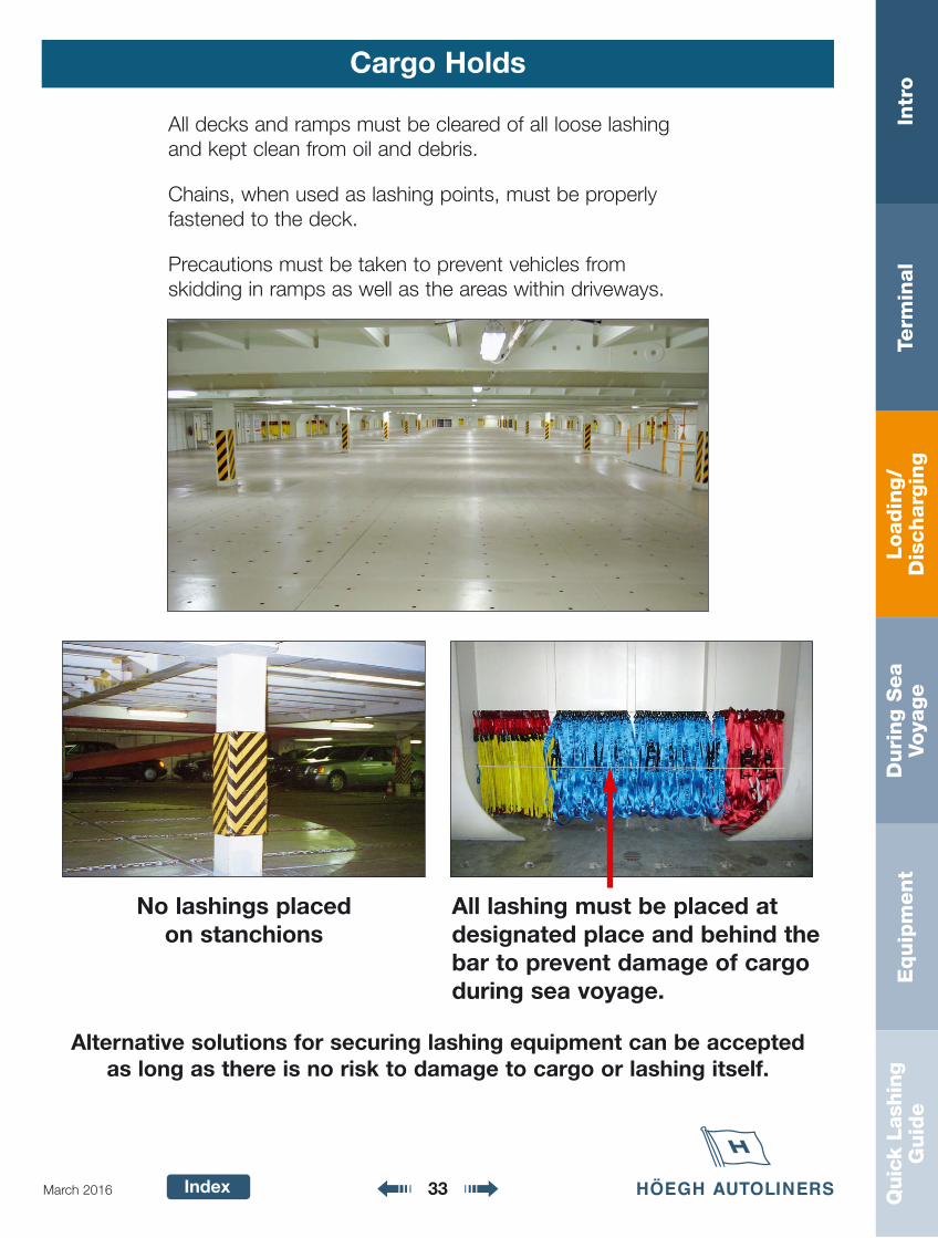
All decks and ramps must be cleared of all loose lashingand kept clean from oil and debris.
Chains, when used as lashing points, must be properly fastened to the deck.
Precautions must be taken to prevent vehicles from skidding in ramps as well as the areas within driveways.
No lashings placed on stanchions
All lashing must be placed atdesignated place and behind thebar to prevent damage of cargoduring sea voyage.
Alternative solutions for securing lashing equipment can be accepted as long as there is no risk to damage to cargo or lashing itself.
Loadin
g/
Dis
charg
ing
Intr
oTe
rmin
al
Duri
ng S
ea
Voya
ge
Equip
ment
Quic
k La
shin
gG
uid
e
Index 34March 2016
Ramps and Driveways
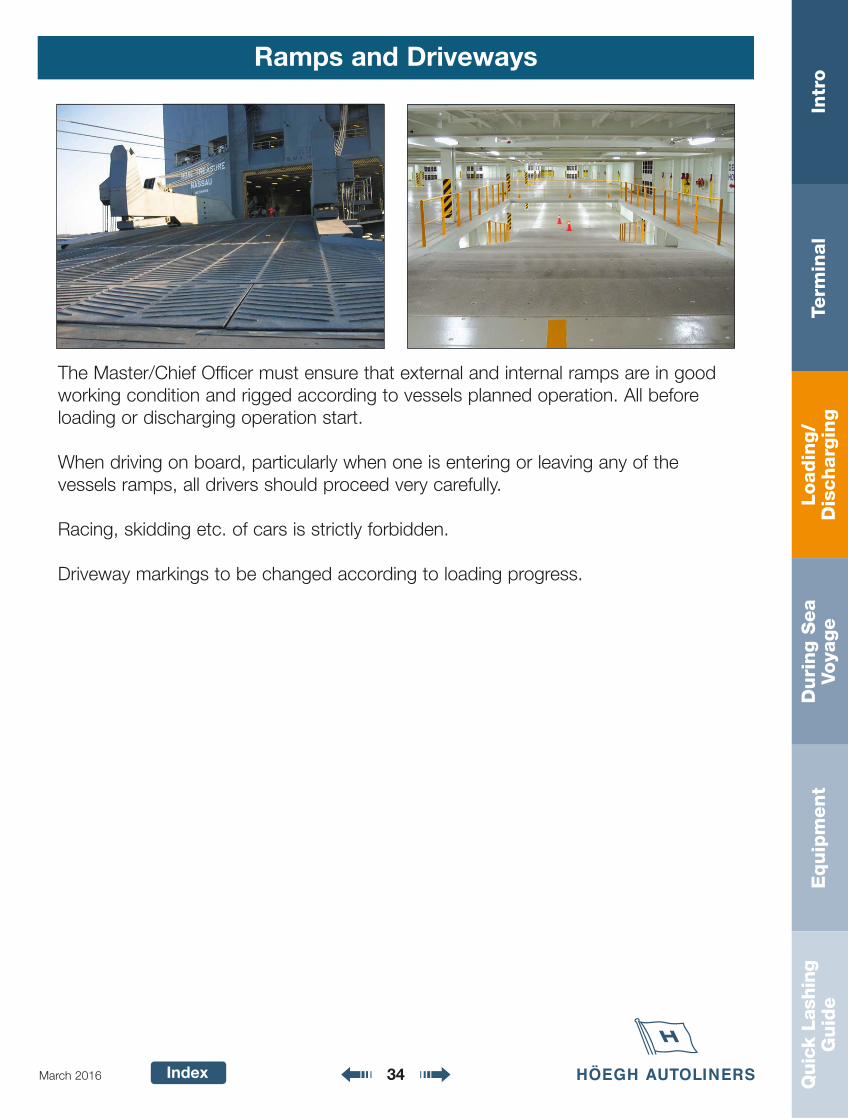
The Master/Chief Officer must ensure that external and internal ramps are in goodworking condition and rigged according to vessels planned operation. All beforeloading or discharging operation start.
When driving on board, particularly when one is entering or leaving any of the vessels ramps, all drivers should proceed very carefully.
Racing, skidding etc. of cars is strictly forbidden.
Driveway markings to be changed according to loading progress.
Loadin
g/
Dis
charg
ing
Intr
oTe
rmin
al
Duri
ng S
ea
Voya
ge
Equip
ment
Quic
k La
shin
gG
uid
e
Index 35March 2016
Ramps and Driveways
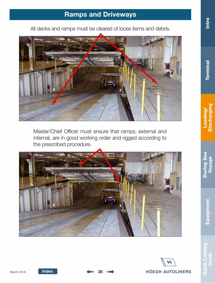
Master/Chief Officer must ensure that ramps, external andinternal, are in good working order and rigged according tothe prescribed procedure.
All decks and ramps must be cleared of loose items and debris.
Loadin
g/
Dis
charg
ing
Intr
oTe
rmin
al
Duri
ng S
ea
Voya
ge
Equip
ment
Quic
k La
shin
gG
uid
e
Index 36March 2016
Ramps and Driveways
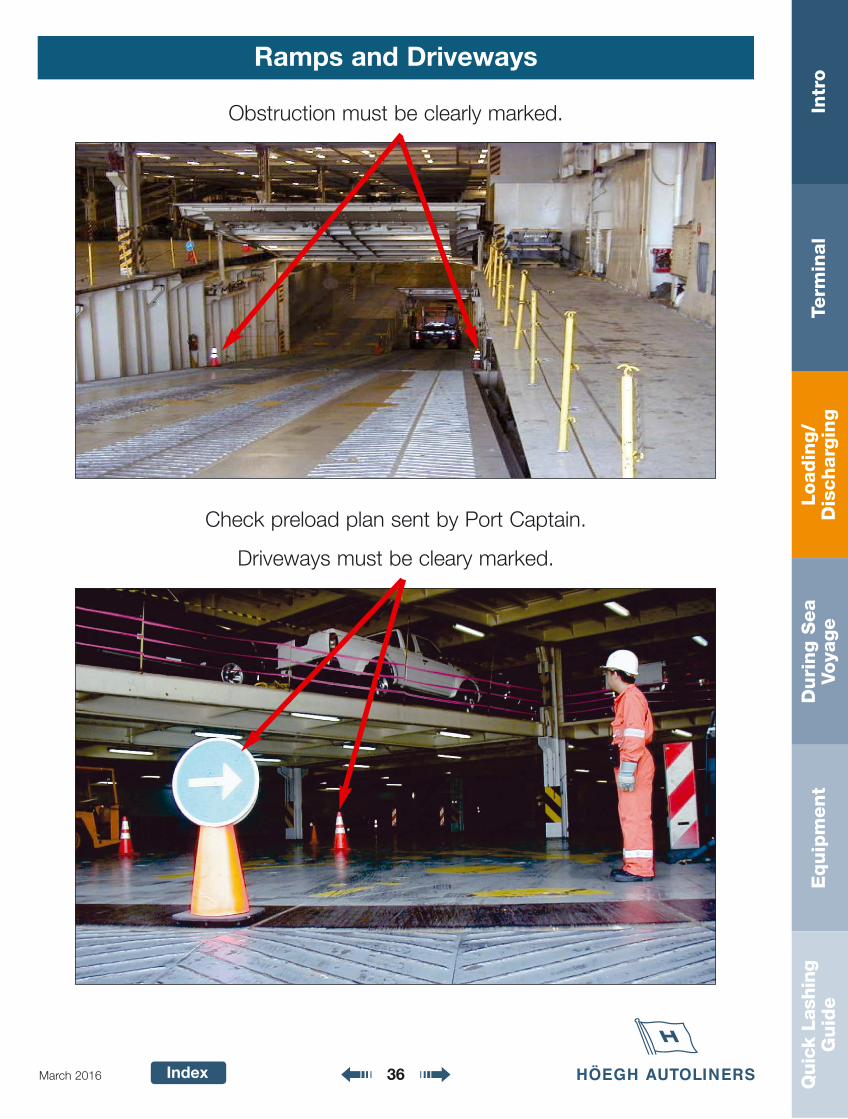
Obstruction must be clearly marked.
Check preload plan sent by Port Captain.
Driveways must be cleary marked.
Loadin
g/
Dis
charg
ing
Intr
oTe
rmin
al
Duri
ng S
ea
Voya
ge
Equip
ment
Quic
k La
shin
gG
uid
e
Index 37March 2016
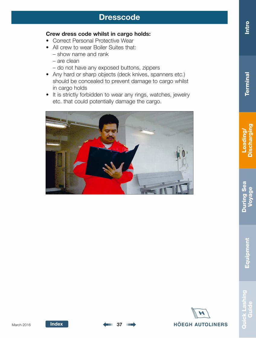
Dresscode
Crew dress code whilst in cargo holds: • Correct Personal Protective Wear• All crew to wear Boiler Suites that:
– show name and rank– are clean– do not have any exposed buttons, zippers
• Any hard or sharp objects (deck knives, spanners etc.)should be concealed to prevent damage to cargo whilstin cargo holds
• It is strictly forbidden to wear any rings, watches, jewelryetc. that could potentially damage the cargo.
Loadin
g/
Dis
charg
ing
Intr
oTe
rmin
al
Duri
ng S
ea
Voya
ge
Equip
ment
Quic
k La
shin
gG
uid
e
Index 38March 2016
Vessels Routines
Vessel routines during cargo operations:
1. Master must ensure that the Chief Officer, has the correct stowplan and these have been distributed to the junior officers andother crew members that are involved in the discharge operation.
2. Duty Officer should report to Chief Officer when load and discharge operation has been completed on each deck. Make sure that all cargo has been discharged.
3. Before closing the ramp or signing tally papers, the Chief OfficerMUST inspect the discharged deck to ensure that no cargo is leftbehind on board.
4. Master must ensure that cargo that has been re-routed (changeof destination) by Höegh Autoliners is marked off by separationtape.
5. The Master must ensure himself that these routines are known byhis crew and always are adhered to.
Crew Members Duties
Crew member duties during cargo operations:
• Officers and crew to be placed on decks where cargo operationare in progress in order to actively supervise the cargo operationand ensure compliance to Höegh Autoliners cargo quality stan-dards and see to that these rules are followed during cargo oper-ation.
• Have an updated stow plan, and have complete overview of theDischarge & loading sequence(s)
• Other typical crew member duties could be (but not limited to):• Plan, prepare and distribute lashing and lashing equipment
throughout cargo operation.
Loadin
g/
Dis
charg
ing
Intr
oTe
rmin
al
Duri
ng S
ea
Voya
ge
Equip
ment
Quic
k La
shin
gG
uid
e
Index 39March 2016
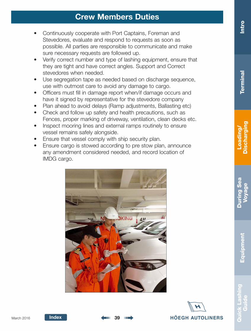
Crew Members Duties
• Continuously cooperate with Port Captains, Foreman andStevedores, evaluate and respond to requests as soon as possible. All parties are responsible to communicate and makesure necessary requests are followed up.
• Verify correct number and type of lashing equipment, ensure thatthey are tight and have correct angles. Support and Correctstevedores when needed.
• Use segregation tape as needed based on discharge sequence,use with outmost care to avoid any damage to cargo.
• Officers must fill in damage report when/if damage occurs andhave it signed by representative for the stevedore company
• Plan ahead to avoid delays (Ramp adjustments, Ballasting etc)• Check and follow up safety and health precautions, such as
Fences, proper marking of driveway, ventilation, clean decks etc.• Inspect mooring lines and external ramps routinely to ensure
vessel remains safely alongside. • Ensure that vessel comply with ship security plan.• Ensure cargo is stowed according to pre stow plan, announce
any amendment considered needed, and record location of IMDG cargo.
Loadin
g/
Dis
charg
ing
Intr
oTe
rmin
al
Duri
ng S
ea
Voya
ge
Equip
ment
Quic
k La
shin
gG
uid
e
Index 40March 2016
Ventilation of Cargo Holds
During cargo operation in port, the ventilation in the cargoholds must give sufficient air exchange per hour to obtainhealthy air for safe working condition.
Follow instruction from maker/owner on supply and exhaust.
Loadin
g/
Dis
charg
ing
Intr
oTe
rmin
al
Duri
ng S
ea
Voya
ge
Equip
ment
Quic
k La
shin
gG
uid
e
Index 41March 2016
Ramp Meeting
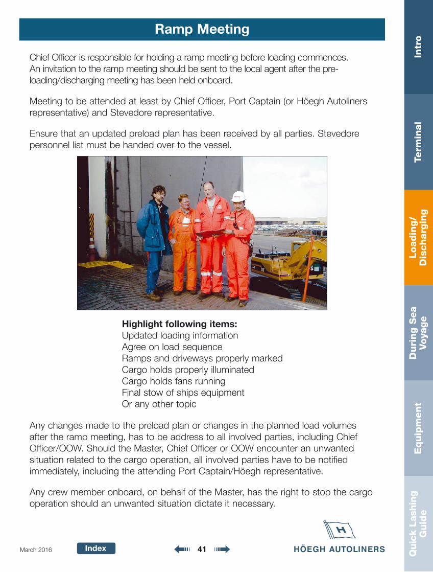
Chief Officer is responsible for holding a ramp meeting before loading commences. An invitation to the ramp meeting should be sent to the local agent after the pre-loading/discharging meeting has been held onboard.
Meeting to be attended at least by Chief Officer, Port Captain (or Höegh Autolinersrepresentative) and Stevedore representative.
Ensure that an updated preload plan has been received by all parties. Stevedorepersonnel list must be handed over to the vessel.
Highlight following items:Updated loading informationAgree on load sequenceRamps and driveways properly markedCargo holds properly illuminatedCargo holds fans runningFinal stow of ships equipmentOr any other topic
Any changes made to the preload plan or changes in the planned load volumesafter the ramp meeting, has to be address to all involved parties, including ChiefOfficer/OOW. Should the Master, Chief Officer or OOW encounter an unwanted situation related to the cargo operation, all involved parties have to be notifiedimmediately, including the attending Port Captain/Höegh representative.
Any crew member onboard, on behalf of the Master, has the right to stop the cargo operation should an unwanted situation dictate it necessary.
Loadin
g/
Dis
charg
ing
Intr
oTe
rmin
al
Duri
ng S
ea
Voya
ge
Equip
ment
Quic
k La
shin
gG
uid
e
Index 42March 2016
Unlashing
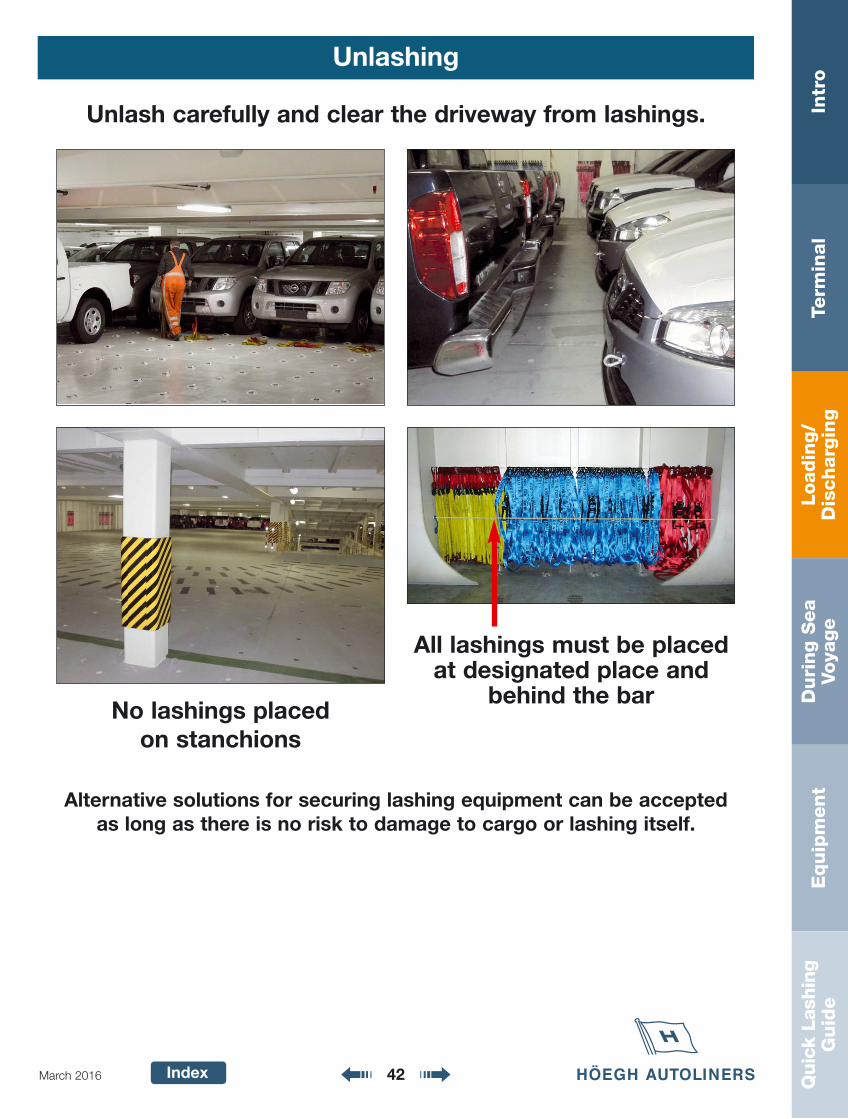
Unlash carefully and clear the driveway from lashings.
All lashings must be placedat designated place and
behind the barNo lashings placed
on stanchions
Alternative solutions for securing lashing equipment can be accepted as long as there is no risk to damage to cargo or lashing itself.
Loadin
g/
Dis
charg
ing
Intr
oTe
rmin
al
Duri
ng S
ea
Voya
ge
Equip
ment
Quic
k La
shin
gG
uid
e
Index 43March 2016
Höegh Autoliners Stowage Standard
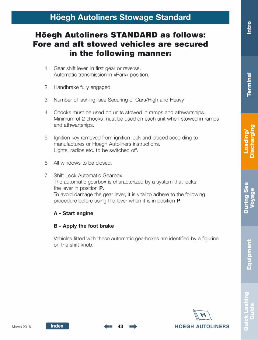
Höegh Autoliners STANDARD as follows:Fore and aft stowed vehicles are secured
in the following manner:
1 Gear shift lever, in first gear or reverse. Automatic transmission in «Park» position.
2 Handbrake fully engaged.
3 Number of lashing, see Securing of Cars/High and Heavy
4 Chocks must be used on units stowed in ramps and athwartships. Minimum of 2 chocks must be used on each unit when stowed in rampsand athwartships.
5 Ignition key removed from ignition lock and placed according to manufactures or Höegh Autoliners instructions.Lights, radios etc. to be switched off.
6 All windows to be closed.
7 Shift Lock Automatic GearboxThe automatic gearbox is characterized by a system that locks the lever in position P.To avoid damage the gear lever, it is vital to adhere to the following procedure before using the lever when it is in position P:
A - Start engine
B - Apply the foot brake
Vehicles fitted with these automatic gearboxes are identified by a figurine on the shift knob.
Loadin
g/
Dis
charg
ing
Intr
oTe
rmin
al
Duri
ng S
ea
Voya
ge
Equip
ment
Quic
k La
shin
gG
uid
e
Index 44March 2016
Höegh Autoliners Stowage Standard
IF NO OEM SPECIAL REQUIREMENT HÖEGH AUTOLINERS GENERAL STOWAGE SYSTEM TO BE USED
PREFERABLY BUMPERS IN LINEMODEL BY MODEL
Right/Left Hand Driven
Minimum distances
Bumper to bumper 30 cm
Side to side 10 cm
Side mirror to side mirror 2-5 cm
Side to obstruction 15 cm
Bumper to bulk head 30 cm
Overhead 10 cm
Walkway 50 cm
Emergency exit and ladders 50 cm
Loadin
g/
Dis
charg
ing
Intr
oTe
rmin
al
Duri
ng S
ea
Voya
ge
Equip
ment
Quic
k La
shin
gG
uid
e
Index 45March 2016
Höegh Autoliners Stowage Standard
W A L K W A Y
WALKWAY
1m, min
1m, min 12
3
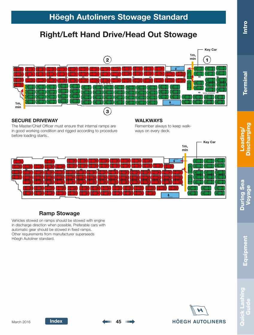
Right/Left Hand Drive/Head Out Stowage
WALKWAYSRemember always to keep walk-ways on every deck.
SECURE DRIVEWAYThe Master/Chief Officer must ensure that internal ramps arein good working condition and rigged according to procedurebefore loading starts..
Key Car
1m, min
Key Car
Ramp StowageVehicles stowed on ramps should be stowed with enginein discharge direction when possible, Preferable cars withautomatic gear should be stowed in fixed ramps.Other requirements from manufacturer superseeds Höegh Autoliner standard.
Loadin
g/
Dis
charg
ing
Intr
oTe
rmin
al
Duri
ng S
ea
Voya
ge
Equip
ment
Quic
k La
shin
gG
uid
e
Index 46March 2016
Entering/Leaving Cars
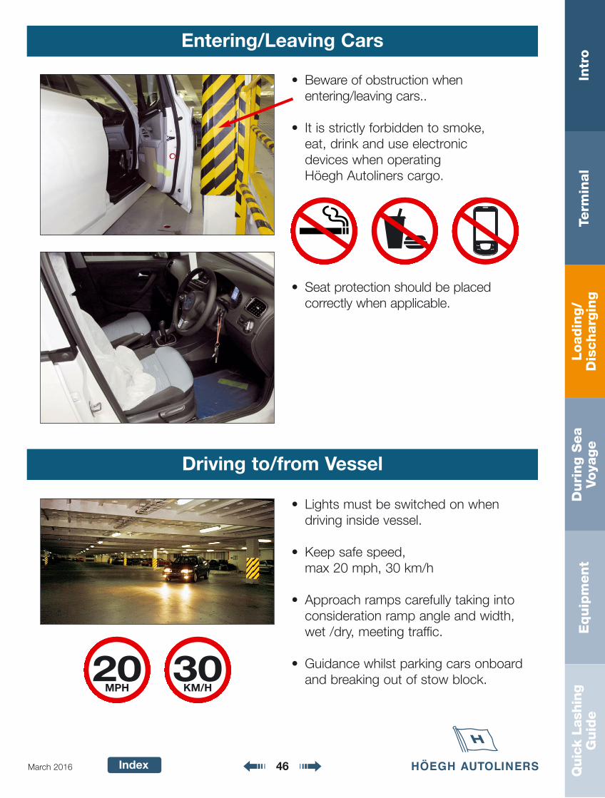
• Beware of obstruction when entering/leaving cars..
• It is strictly forbidden to smoke, eat, drink and use electronic devices when operating Höegh Autoliners cargo.
• Seat protection should be placed correctly when applicable.
• Lights must be switched on when driving inside vessel.
• Keep safe speed, max 20 mph, 30 km/h
• Approach ramps carefully taking intoconsideration ramp angle and width,wet /dry, meeting traffic.
• Guidance whilst parking cars onboardand breaking out of stow block.
Driving to/from Vessel
MPH
Loadin
g/
Dis
charg
ing
Intr
oTe
rmin
al
Duri
ng S
ea
Voya
ge
Equip
ment
Quic
k La
shin
gG
uid
e
Index 47March 2016
Tally
Tally should take place on or near the external ramps of the vessel.
Tally company must check that cargo is loaded/discharged accordingto the deck plans and number/position of loaded units are to benoted.
Prior to Vessel Departure
1 The tally shall supply a detailed and accurate stowage plan to thevessel, agents and Port Captain
2 The stowage plan must include the following information:• Shifted/re-stowed units• Direction of the stow• Discharge port and Load port• Dangerous goods to be specifically marked• Total weight of the cargo loaded; marked for each deck• Weight of units in block• Number of units loaded must be split into FNLV
(including OEM brand), POV, HH and Break bulk per hold and deck
• A breakdown of what break bulk cargo has been loaded onto or discharged from a roll trailer as well as recording the roll trailer number
3 Tally papers to consist of; (1) Höegh Autoliners Summary Sheet (load, discharge and T/S); (2) Stowage plan; (3) Rolltrailer Stuffing List
4 Prior to departure Tally papers to be handed over to: (1) Höegh Autoliners Agent; (2) Höegh Autoliners Port Captain;(3) Vessel’s Master
Loadin
g/
Dis
charg
ing
Intr
oTe
rmin
al
Duri
ng S
ea
Voya
ge
Equip
ment
Quic
k La
shin
gG
uid
e
Index 48March 2016
Tally
5 On completion of the loading/discharging operation, a work reportmust prior to departure be sent/given to agent/vessel’s Master.
The report is to contain the following information:• Number of units discharged/loaded (including T/S units)• VIN no• Vehicle make and model• Load port and discharge port, including final destinations for
T/S cargo• A record of all re-stows, both onboard and via quay side
Tally papers are to be handed over to Höegh Autoliners Agent,Höegh Autoliners Port Captain and Vessel’s Master prior to departure.
Vessel to verify and report significant discrepancies between tallyand pre stow plan.
Loadin
g/
Dis
charg
ing
Intr
oTe
rmin
al
Duri
ng S
ea
Voya
ge
Equip
ment
Quic
k La
shin
gG
uid
e
Index 49March 2016
Höegh Autoliners Lashing Standard
The following types of lashing equipment should be used for differenttypes of cargo:
• Cars, p/ups and light cargo units 0 – 3000 kg shall be secured by car lashings with a break load of minimum 2000 kg and MSL minimum 1000 kg.
• High and Heavy units with weights between 3000 – 10 000 kgshall be preferably secured by Rollash with a break load of minimum 5000 kg and MSL minimum 2500 kg.
• High and Heavy units with weights above 10 000 kg shall besecured by Heavy Duty Webb Lash with a break load of minimum10 000 kg and MSL minimum 5000 kg. Rollash can be used asan alternative provided that total number of lashings equials thetoral required MSL.
• High and Heavy units with weights above 150 000 kg shall besecured by Heavy Heavy Duty Webb Lash with a break load ofminimum 20 000 kg and MSL minimum 10 000 kg. Heavy DutyWebb Lash can be used as an alternative provided that totalnumber of lashings equials the toral required MSL.
NB do not mix Heavy Heavy Duty Webb lash withHeavy Duty Webb Lash or Rollash, in any
combination, on same unit.

Loadin
g/
Dis
charg
ing
Intr
oTe
rmin
al
Duri
ng S
ea
Voya
ge
Equip
ment
Quic
k La
shin
gG
uid
e
Index 50March 2016
Securing of Cars and Light Cargo 0 - 3000 kg
Höegh Autoliners Ro-Ro CarlashingWorking instructions
CarlashingsCar lashings (type Höegh AutolinersRo-Ro lash) Breaking load 2000 kg MSL 1000 kg for cars, p/u and units upto 3000 kg.
Cars stowed fore-and-aft. min. 4 lashingsCars stowed in ramps min. 5 lashings**Cars stowed athwartships min. 6 lashings The lashing should be properly tightened
** Cars stowed athwartships(alternate option) min. 4 lashings + 2 car chocks
1 2
3
NB! Some manufacturers may requiredifferent lashing standards.
Correct use of Höegh Autoliners Car Sling
Loadin
g/
Dis
charg
ing
Intr
oTe
rmin
al
Duri
ng S
ea
Voya
ge
Equip
ment
Quic
k La
shin
gG
uid
e
Index 51March 2016
Securing of Cars and Light Cargo 0 - 3000 kg
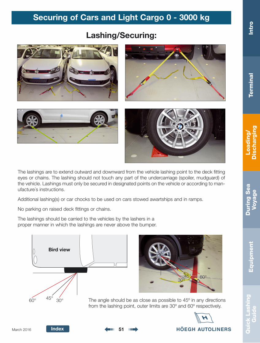
Lashing/Securing:
The lashings are to extend outward and downward from the vehicle lashing point to the deck fittingeyes or chains. The lashing should not touch any part of the undercarriage (spoiler, mudguard) ofthe vehicle. Lashings must only be secured in designated points on the vehicle or according to man-ufacture´s instructions.
Additional lashing(s) or car chocks to be used on cars stowed awartships and in ramps.
No parking on raised deck fittings or chains.
The lashings should be carried to the vehicles by the lashers in a proper manner in which the lashings are never above the bumper.
The angle should be as close as possible to 45º in any directionsfrom the lashing point, outer limits are 30º and 60º respectively.
60° 30°45°
Bird view
30°45° 60°
Loadin
g/
Dis
charg
ing
Intr
oTe
rmin
al
Duri
ng S
ea
Voya
ge
Equip
ment
Quic
k La
shin
gG
uid
e
Index 52March 2016
Höegh Autoliners Stowage Standard - High and Heavy
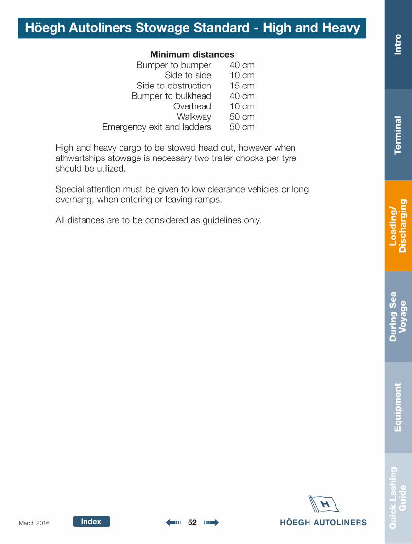
Minimum distancesBumper to bumper 40 cm
Side to side 10 cmSide to obstruction 15 cm
Bumper to bulkhead 40 cmOverhead 10 cmWalkway 50 cm
Emergency exit and ladders 50 cm
High and heavy cargo to be stowed head out, however whenathwartships stowage is necessary two trailer chocks per tyre should be utilized.
Special attention must be given to low clearance vehicles or longoverhang, when entering or leaving ramps.
All distances are to be considered as guidelines only.
Loadin
g/
Dis
charg
ing
Intr
oTe
rmin
al
Duri
ng S
ea
Voya
ge
Equip
ment
Quic
k La
shin
gG
uid
e
Index 53March 2016
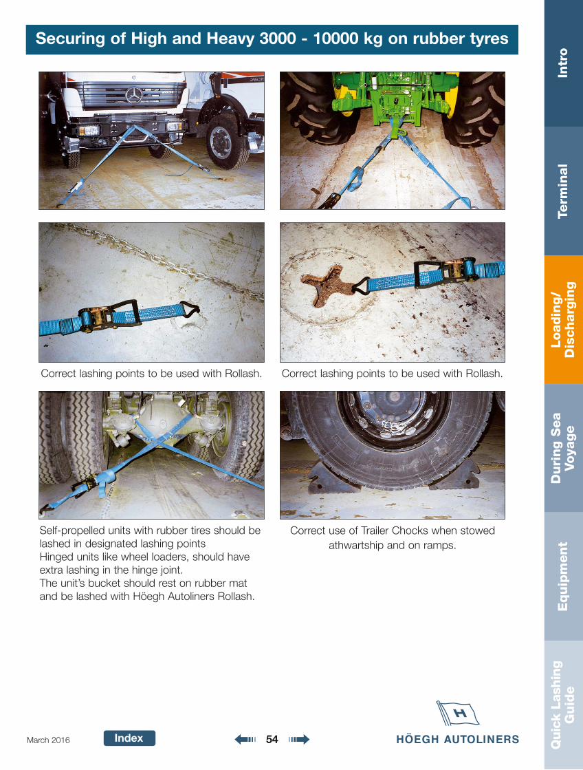
Securing of High and Heavy 3000 - 10000 kg on rubber tyres
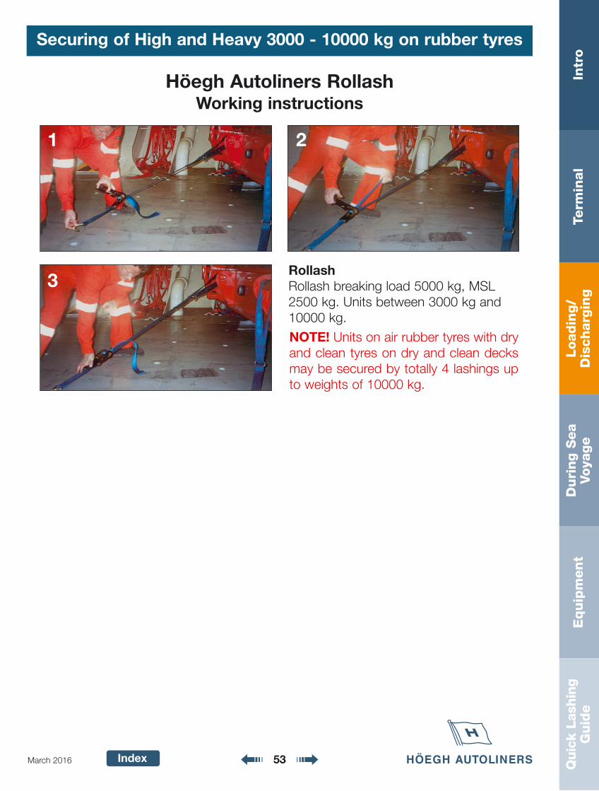
Höegh Autoliners RollashWorking instructions
RollashRollash breaking load 5000 kg, MSL2500 kg. Units between 3000 kg and10000 kg.
1 2
3
NOTE! Units on air rubber tyres with dryand clean tyres on dry and clean decksmay be secured by totally 4 lashings upto weights of 10000 kg.
Loadin
g/
Dis
charg
ing
Intr
oTe
rmin
al
Duri
ng S
ea
Voya
ge
Equip
ment
Quic
k La
shin
gG
uid
e
Index 54March 2016
Correct use of Trailer Chocks when stowedathwartship and on ramps.
Correct lashing points to be used with Rollash. Correct lashing points to be used with Rollash.
Self-propelled units with rubber tires should belashed in designated lashing pointsHinged units like wheel loaders, should haveextra lashing in the hinge joint.The unit’s bucket should rest on rubber matand be lashed with Höegh Autoliners Rollash.
Securing of High and Heavy 3000 - 10000 kg on rubber tyres

Loadin
g/
Dis
charg
ing
Intr
oTe
rmin
al
Duri
ng S
ea
Voya
ge
Equip
ment
Quic
k La
shin
gG
uid
e
Index 55March 2016
Chassis
Chassis must be lashed in designated lashing points toavoid damage. Always use Höegh Autoliners Rollash regard-less if unit weight exceeds 10 000 kg. Number of lashingaccording to units weight and MSL of Rollash.
LASHINGPOINT
LASHING POINT
LASHING POINT
TO PLACE TEFLON BILLETS
Loadin
g/
Dis
charg
ing
Intr
oTe
rmin
al
Duri
ng S
ea
Voya
ge
Equip
ment
Quic
k La
shin
gG
uid
e
Index 56March 2016
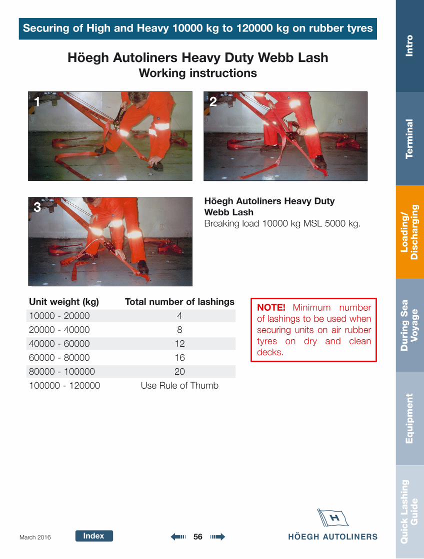
Höegh Autoliners Heavy Duty Webb LashWorking instructions
Höegh Autoliners Heavy Duty Webb LashBreaking load 10000 kg MSL 5000 kg.
1 2
3
Unit weight (kg) Total number of lashings
10000 - 20000 4
20000 - 40000 8
40000 - 60000 12
60000 - 80000 16
80000 - 100000 20
100000 - 120000 Use Rule of Thumb
NOTE! Minimum numberof lashings to be used whensecuring units on air rubbertyres on dry and cleandecks.
Securing of High and Heavy 10000 kg to 120000 kg on rubber tyres
Loadin
g/
Dis
charg
ing
Intr
oTe
rmin
al
Duri
ng S
ea
Voya
ge
Equip
ment
Quic
k La
shin
gG
uid
e
Index 57March 2016
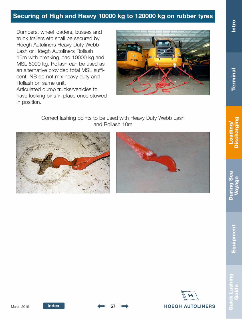
Securing of High and Heavy 10000 kg to 120000 kg on rubber tyres
Dumpers, wheel loaders, busses andtruck trailers etc shall be secured byHöegh Autoliners Heavy Duty WebbLash or Höegh Autoliners Rollash 10m with breaking load 10000 kg andMSL 5000 kg. Rollash can be used asan alternative provided total MSL suffi-cent. NB do not mix heavy duty andRollash on same unit.Articulated dump trucks/vehicles tohave locking pins in place once stowedin position.
Correct lashing points to be used with Heavy Duty Webb Lash and Rollash 10m
Loadin
g/
Dis
charg
ing
Intr
oTe
rmin
al
Duri
ng S
ea
Voya
ge
Equip
ment
Quic
k La
shin
gG
uid
e
Index 58March 2016
Securing with heavy heavy duty weblash 120000 - 200000 kg
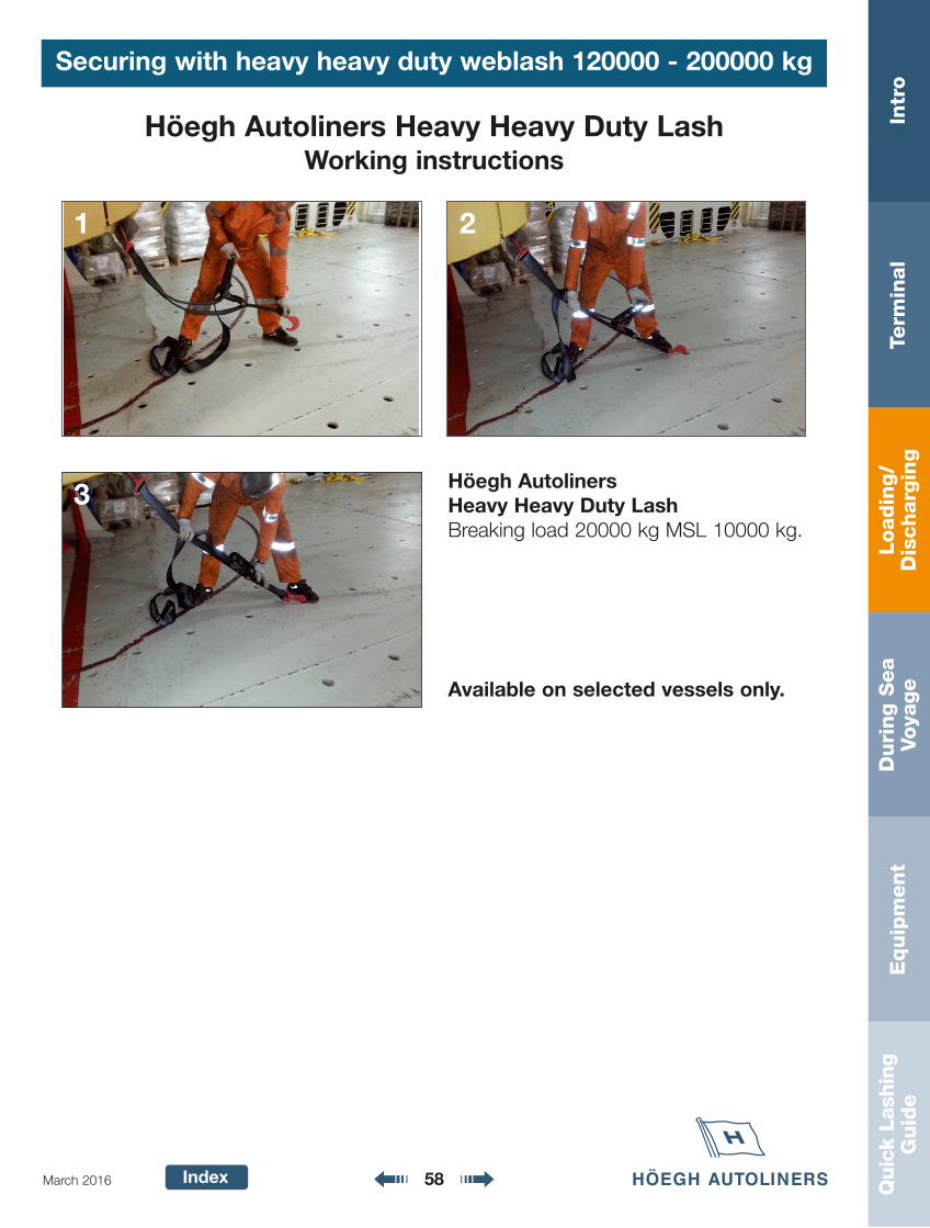
Höegh Autoliners Heavy Heavy Duty LashWorking instructions
Höegh AutolinersHeavy Heavy Duty LashBreaking load 20000 kg MSL 10000 kg.
Available on selected vessels only.
1 2
3
Loadin
g/
Dis
charg
ing
Intr
oTe
rmin
al
Duri
ng S
ea
Voya
ge
Equip
ment
Quic
k La
shin
gG
uid
e
Index 59March 2016
Securing of Static, Roll trailer, Excavators and other H/H not on rubber tyres
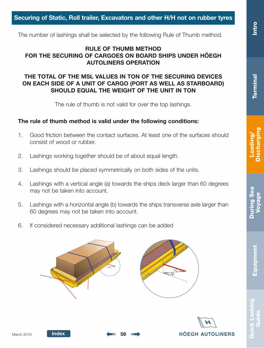
The rule of thumb method is valid under the following conditions:
1. Good friction between the contact surfaces. At least one of the surfaces shouldconsist of wood or rubber.
2. Lashings working together should be of about equal length.
3. Lashings should be placed symmetrically on both sides of the units.
4. Lashings with a vertical angle (a) towards the ships deck larger than 60 degreesmay not be taken into account.
5. Lashings with a horizontal angle (b) towards the ships transverse axle larger than60 degrees may not be taken into account.
6. If considered necessary additional lashings can be added
The number of lashings shall be selected by the following Rule of Thumb method.
RULE OF THUMB METHODFOR THE SECURING OF CARGOES ON BOARD SHIPS UNDER HÖEGH
AUTOLINERS OPERATION
THE TOTAL OF THE MSL VALUES IN TON OF THE SECURING DEVICES ON EACH SIDE OF A UNIT OF CARGO (PORT AS WELL AS STARBOARD)
SHOULD EQUAL THE WEIGHT OF THE UNIT IN TON
The rule of thumb is not valid for over the top lashings.
Loadin
g/
Dis
charg
ing
Intr
oTe
rmin
al
Duri
ng S
ea
Voya
ge
Equip
ment
Quic
k La
shin
gG
uid
e
Index 60March 2016
Securing of Static, Roll trailer, Excavators and other H/H not on rubber tyres
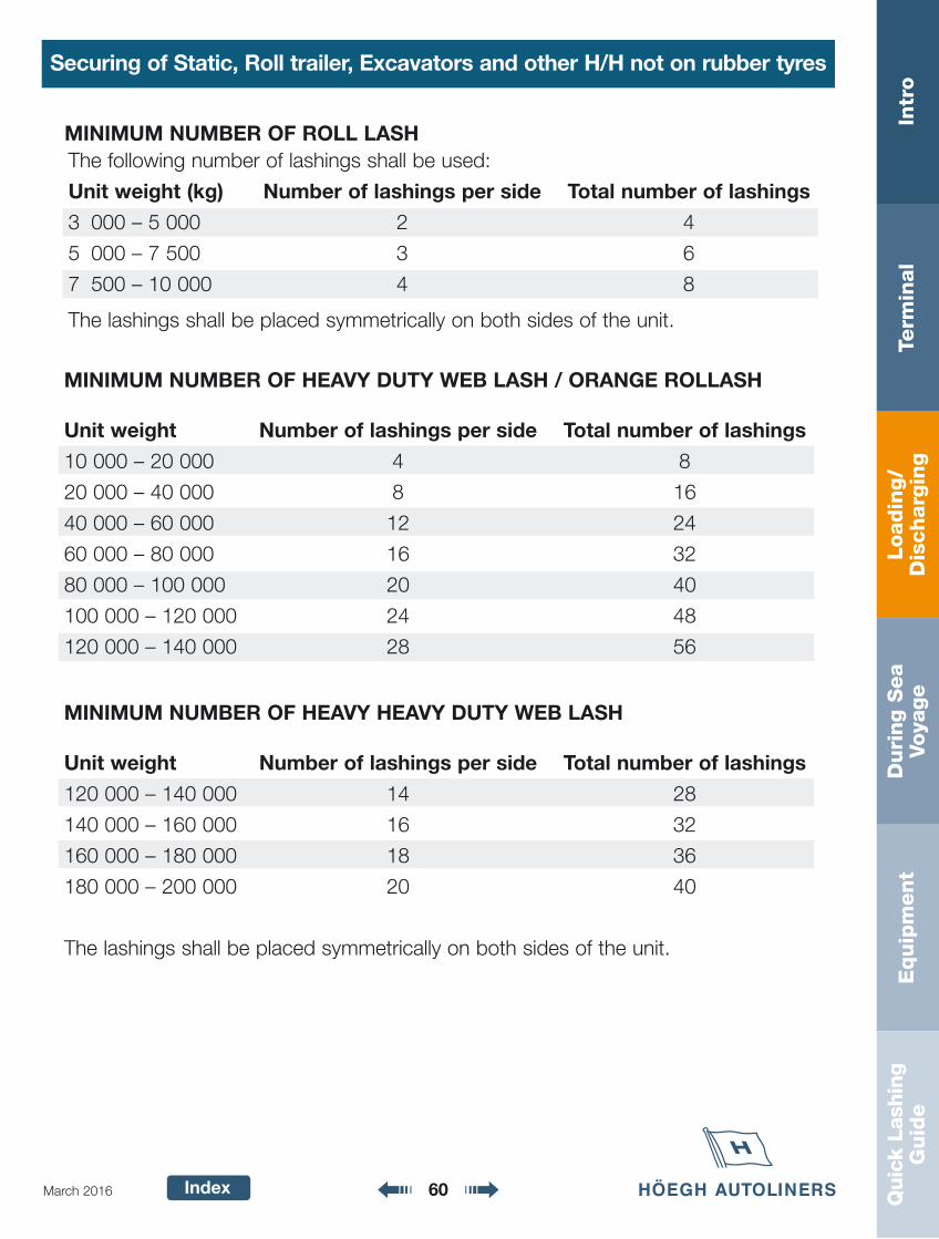
MINIMUM NUMBER OF HEAVY DUTY WEB LASH / ORANGE ROLLASH
Unit weight Number of lashings per side Total number of lashings
10 000 – 20 000 4 8
20 000 – 40 000 8 16
40 000 – 60 000 12 24
60 000 – 80 000 16 32
80 000 – 100 000 20 40
100 000 – 120 000 24 48
120 000 – 140 000 28 56
MINIMUM NUMBER OF HEAVY HEAVY DUTY WEB LASH
Unit weight Number of lashings per side Total number of lashings
120 000 – 140 000 14 28
140 000 – 160 000 16 32
160 000 – 180 000 18 36
180 000 – 200 000 20 40
The following number of lashings shall be used:
Unit weight (kg) Number of lashings per side Total number of lashings
3 000 – 5 000 2 4
5 000 – 7 500 3 6
7 500 – 10 000 4 8
The lashings shall be placed symmetrically on both sides of the unit.
MINIMUM NUMBER OF ROLL LASH
The lashings shall be placed symmetrically on both sides of the unit.
Loadin
g/
Dis
charg
ing
Intr
oTe
rmin
al
Duri
ng S
ea
Voya
ge
Equip
ment
Quic
k La
shin
gG
uid
e
Index 61March 2016
Securing of Static, Roll trailer, Excavators and other H/H not on rubber tyres
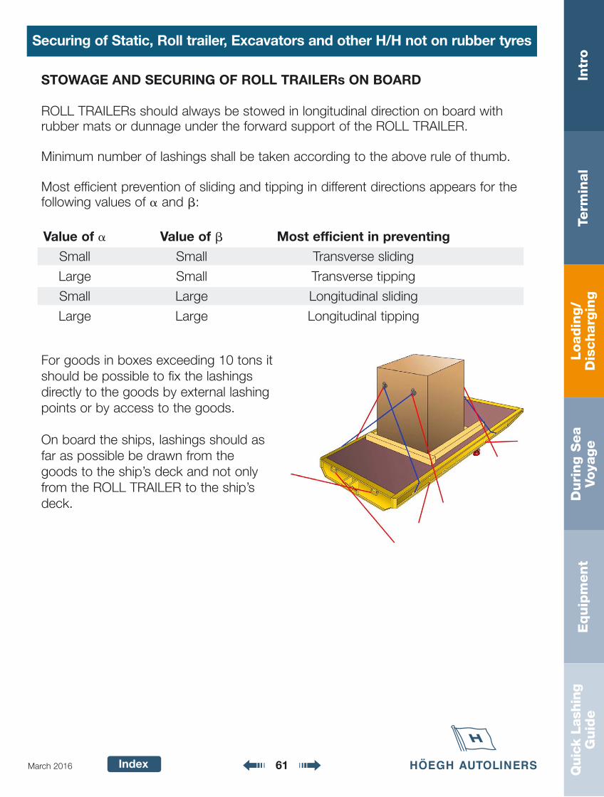
For goods in boxes exceeding 10 tons itshould be possible to fix the lashingsdirectly to the goods by external lashingpoints or by access to the goods.
On board the ships, lashings should asfar as possible be drawn from thegoods to the ship’s deck and not onlyfrom the ROLL TRAILER to the ship’sdeck.
STOWAGE AND SECURING OF ROLL TRAILERs ON BOARD
ROLL TRAILERs should always be stowed in longitudinal direction on board withrubber mats or dunnage under the forward support of the ROLL TRAILER.
Minimum number of lashings shall be taken according to the above rule of thumb.
Most efficient prevention of sliding and tipping in different directions appears for thefollowing values of � and �:
Value of � Value of � Most efficient in preventing
Small Small Transverse sliding
Large Small Transverse tipping
Small Large Longitudinal sliding
Large Large Longitudinal tipping
Loadin
g/
Dis
charg
ing
Intr
oTe
rmin
al
Duri
ng S
ea
Voya
ge
Equip
ment
Quic
k La
shin
gG
uid
e
Index 62March 2016
Securing of Static, Roll trailer, Excavators and other H/H not on rubber tyres
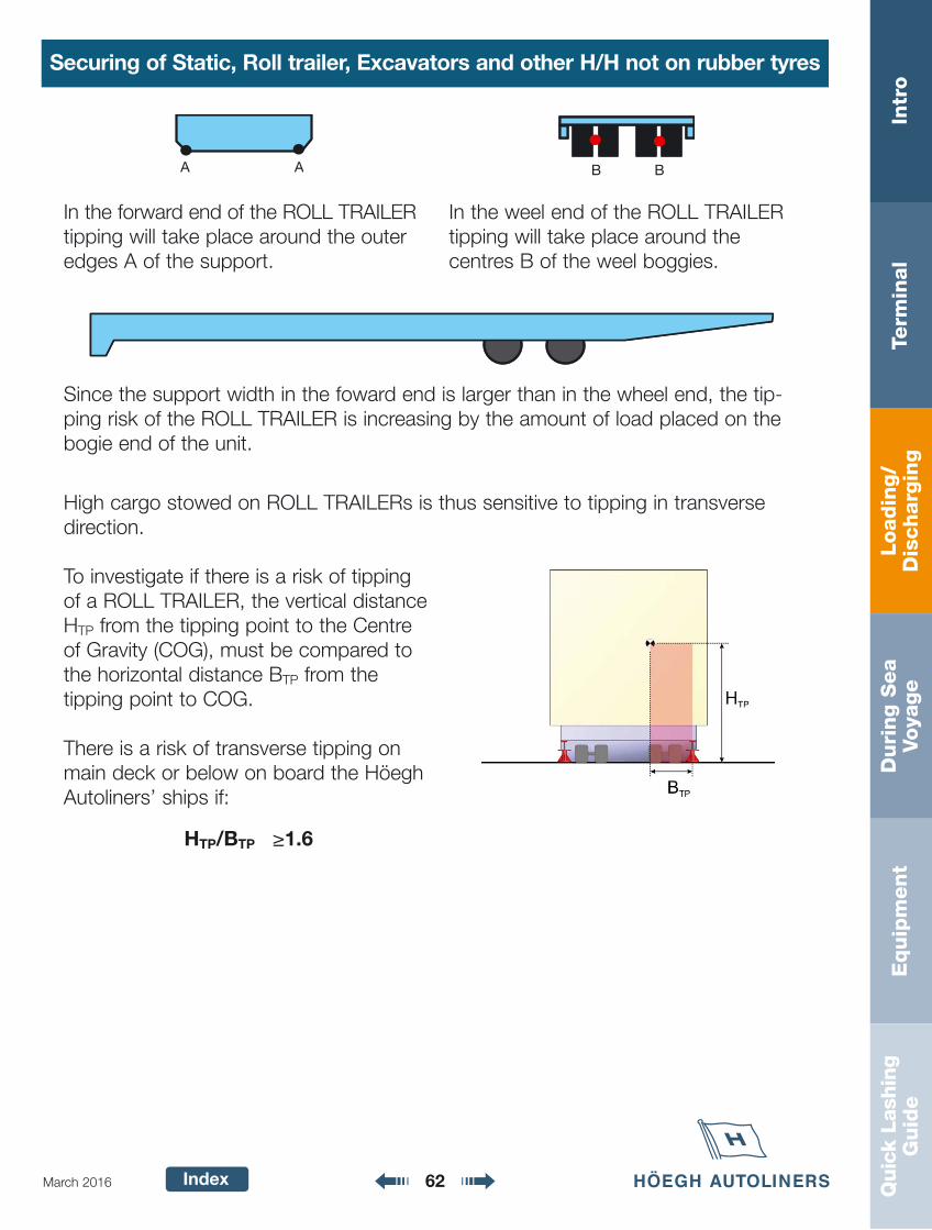
High cargo stowed on ROLL TRAILERs is thus sensitive to tipping in transversedirection.
To investigate if there is a risk of tippingof a ROLL TRAILER, the vertical distanceHTP from the tipping point to the Centreof Gravity (COG), must be compared tothe horizontal distance BTP from the tipping point to COG.
There is a risk of transverse tipping onmain deck or below on board the HöeghAutoliners’ ships if:
HTP/BTP ≥1.6
AA BB
In the forward end of the ROLL TRAILERtipping will take place around the outeredges A of the support.
In the weel end of the ROLL TRAILERtipping will take place around the centres B of the weel boggies.
Since the support width in the foward end is larger than in the wheel end, the tip-ping risk of the ROLL TRAILER is increasing by the amount of load placed on thebogie end of the unit.
Loadin
g/
Dis
charg
ing
Intr
oTe
rmin
al
Duri
ng S
ea
Voya
ge
Equip
ment
Quic
k La
shin
gG
uid
e
Index 63March 2016
Securing of Static, Roll trailer, Excavators and other H/H not on rubber tyres
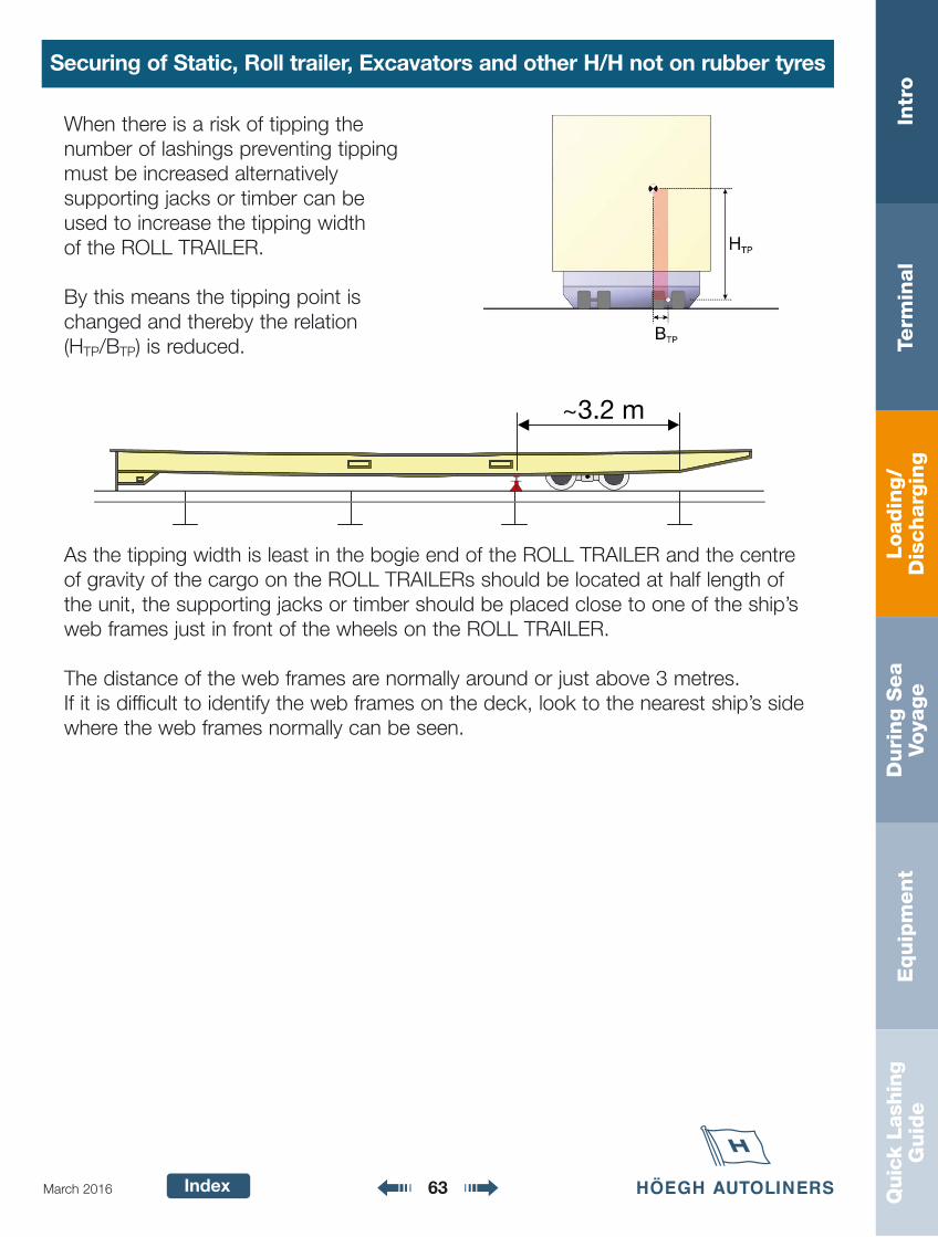
As the tipping width is least in the bogie end of the ROLL TRAILER and the centreof gravity of the cargo on the ROLL TRAILERs should be located at half length ofthe unit, the supporting jacks or timber should be placed close to one of the ship’sweb frames just in front of the wheels on the ROLL TRAILER.
The distance of the web frames are normally around or just above 3 metres.If it is difficult to identify the web frames on the deck, look to the nearest ship’s sidewhere the web frames normally can be seen.
~3.2 m
When there is a risk of tipping the number of lashings preventing tippingmust be increased alternatively supporting jacks or timber can be used to increase the tipping width of the ROLL TRAILER.
By this means the tipping point ischanged and thereby the relation(HTP/BTP) is reduced.
Loadin
g/
Dis
charg
ing
Intr
oTe
rmin
al
Duri
ng S
ea
Voya
ge
Equip
ment
Quic
k La
shin
gG
uid
e
Index 64March 2016
Securing of Static, Roll trailer, Excavators and other H/H not on rubber tyres
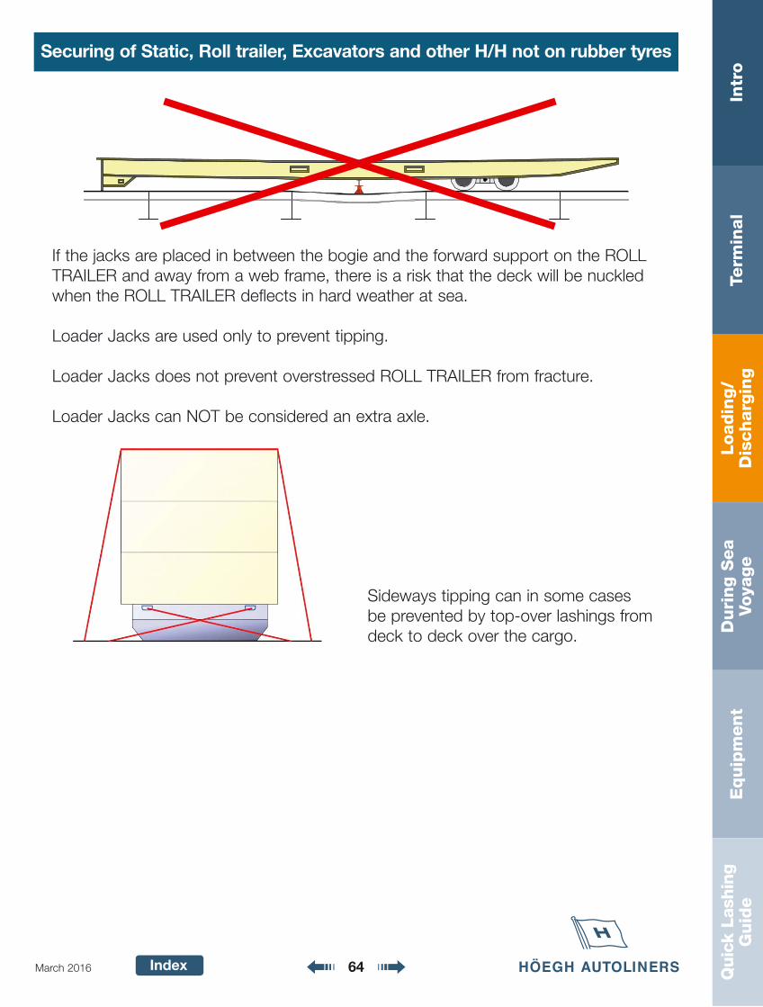
Sideways tipping can in some cases be prevented by top-over lashings fromdeck to deck over the cargo.
If the jacks are placed in between the bogie and the forward support on the ROLLTRAILER and away from a web frame, there is a risk that the deck will be nuckledwhen the ROLL TRAILER deflects in hard weather at sea.
Loader Jacks are used only to prevent tipping.
Loader Jacks does not prevent overstressed ROLL TRAILER from fracture.
Loader Jacks can NOT be considered an extra axle.
Loadin
g/
Dis
charg
ing
Intr
oTe
rmin
al
Duri
ng S
ea
Voya
ge
Equip
ment
Quic
k La
shin
gG
uid
e
Index 65March 2016
Securing of Static, Roll trailer, Excavators and other H/H not on rubber tyres
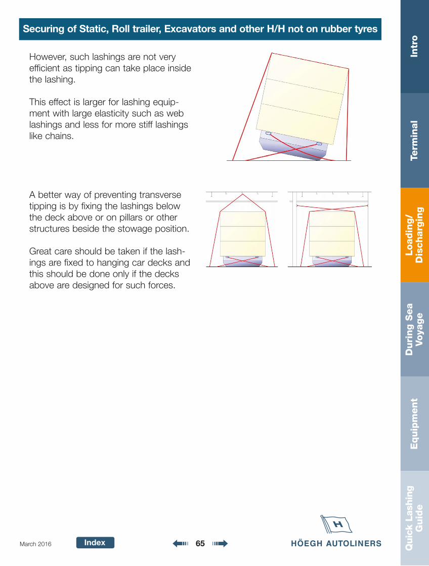
A better way of preventing transversetipping is by fixing the lashings belowthe deck above or on pillars or otherstructures beside the stowage position.
Great care should be taken if the lash-ings are fixed to hanging car decks andthis should be done only if the decksabove are designed for such forces.
However, such lashings are not very efficient as tipping can take place insidethe lashing.
This effect is larger for lashing equip-ment with large elasticity such as weblashings and less for more stiff lashingslike chains.
Loadin
g/
Dis
charg
ing
Intr
oTe
rmin
al
Duri
ng S
ea
Voya
ge
Equip
ment
Quic
k La
shin
gG
uid
e
Index 66March 2016
Securing of Static, Roll trailer, Excavators and other H/H not on rubber tyres
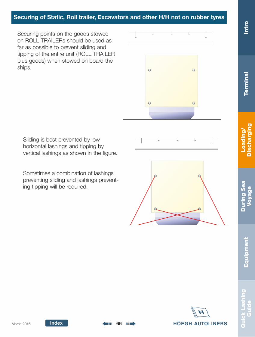
Securing points on the goods stowedon ROLL TRAILERs should be used asfar as possible to prevent sliding andtipping of the entire unit (ROLL TRAILERplus goods) when stowed on board theships.
Sliding is best prevented by low horizontal lashings and tipping by vertical lashings as shown in the figure.
Sometimes a combination of lashingspreventing sliding and lashings prevent-ing tipping will be required.
Loadin
g/
Dis
charg
ing
Intr
oTe
rmin
al
Duri
ng S
ea
Voya
ge
Equip
ment
Quic
k La
shin
gG
uid
e
Index 67March 2016
Securing of Static, Roll trailer, Excavators and other H/H not on rubber tyres
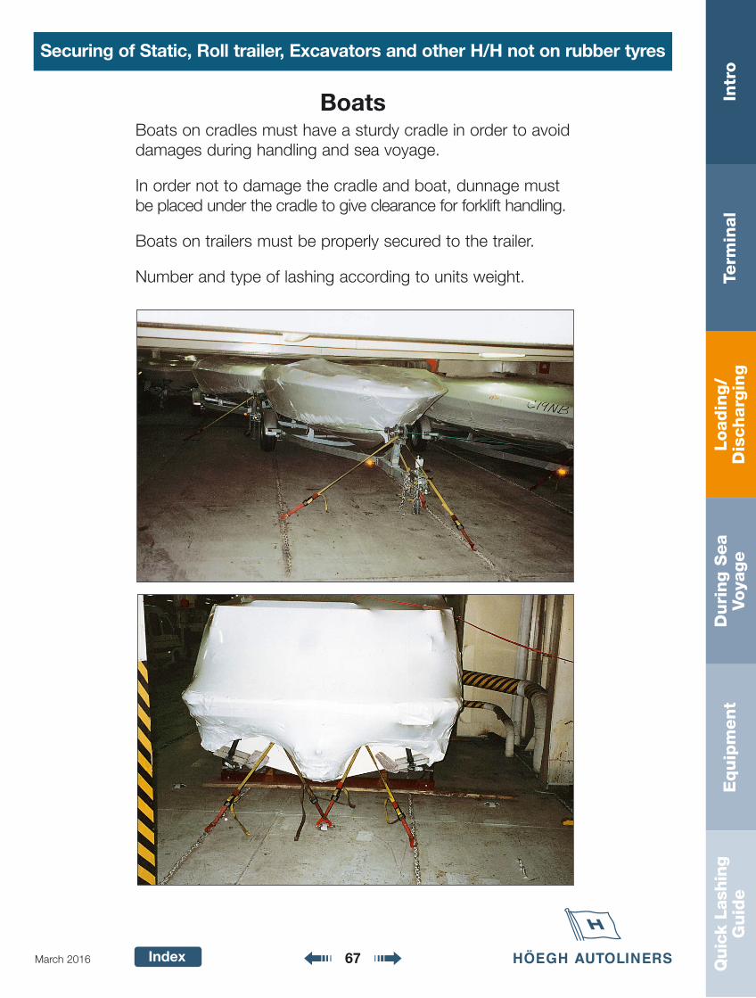
BoatsBoats on cradles must have a sturdy cradle in order to avoiddamages during handling and sea voyage.
In order not to damage the cradle and boat, dunnage mustbe placed under the cradle to give clearance for forklift handling.
Boats on trailers must be properly secured to the trailer.
Number and type of lashing according to units weight.
Loadin
g/
Dis
charg
ing
Intr
oTe
rmin
al
Duri
ng S
ea
Voya
ge
Equip
ment
Quic
k La
shin
gG
uid
e
Index 68March 2016
Securing of Static, Roll trailer, Excavators and other H/H not on rubber tyres
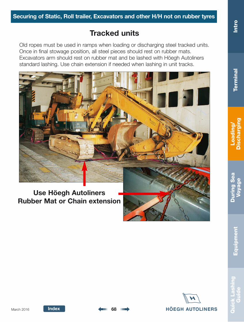
Tracked unitsOld ropes must be used in ramps when loading or discharging steel tracked units.Once in final stowage position, all steel pieces should rest on rubber mats.Excavators arm should rest on rubber mat and be lashed with Höegh Autolinersstandard lashing. Use chain extension if needed when lashing in unit tracks.
Use Höegh AutolinersRubber Mat or Chain extension
Loadin
g/
Dis
charg
ing
Intr
oTe
rmin
al
Duri
ng S
ea
Voya
ge
Equip
ment
Quic
k La
shin
gG
uid
e
Index
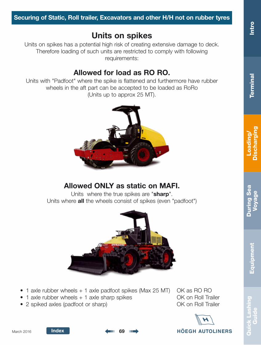
Units on spikesUnits on spikes has a potential high risk of creating extensive damage to deck.
Therefore loading of such units are restricted to comply with following requirements:
Allowed for load as RO RO.Units with "Padfoot" where the spike is flattened and furthermore have rubber
wheels in the aft part can be accepted to be loaded as RoRo (Units up to approx 25 MT).
Allowed ONLY as static on MAFI.Units where the true spikes are "sharp".
Units where all the wheels consist of spikes (even "padfoot")
• 1 axle rubber wheels + 1 axle padfoot spikes (Max 25 MT) OK as RO RO• 1 axle rubber wheels + 1 axle sharp spikes OK on Roll Trailer• 2 spiked axles (padfoot or sharp) OK on Roll Trailer
69March 2016
Securing of Static, Roll trailer, Excavators and other H/H not on rubber tyres
Loadin
g/
Dis
charg
ing
Intr
oTe
rmin
al
Duri
ng S
ea
Voya
ge
Equip
ment
Quic
k La
shin
gG
uid
e
Index 70March 2016
Used or Damaged Units
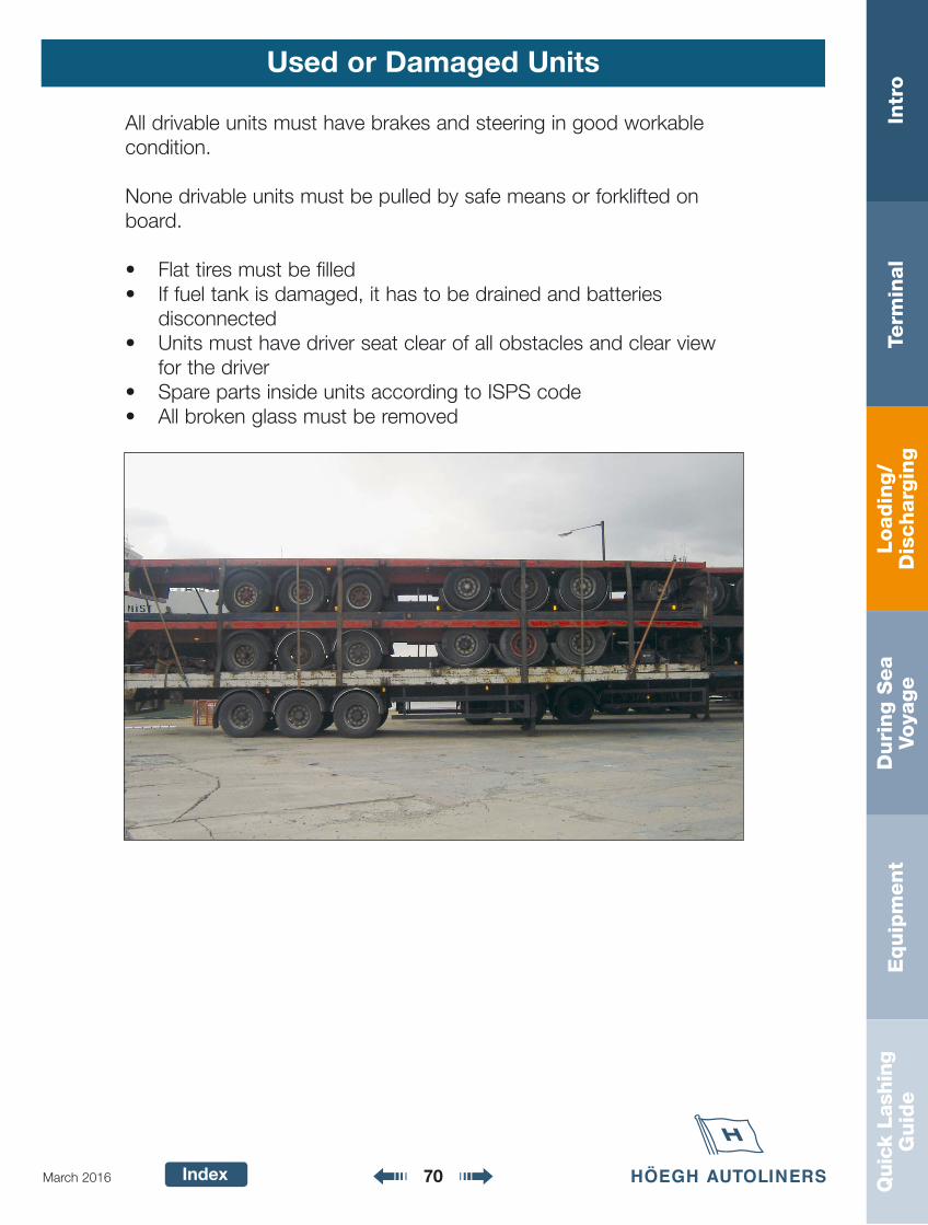
All drivable units must have brakes and steering in good workablecondition.
None drivable units must be pulled by safe means or forklifted onboard.
• Flat tires must be filled• If fuel tank is damaged, it has to be drained and batteries
disconnected• Units must have driver seat clear of all obstacles and clear view
for the driver• Spare parts inside units according to ISPS code• All broken glass must be removed
Loadin
g/
Dis
charg
ing
Intr
oTe
rmin
al
Duri
ng S
ea
Voya
ge
Equip
ment
Quic
k La
shin
gG
uid
e
Index 71March 2016
Used or Damaged Units
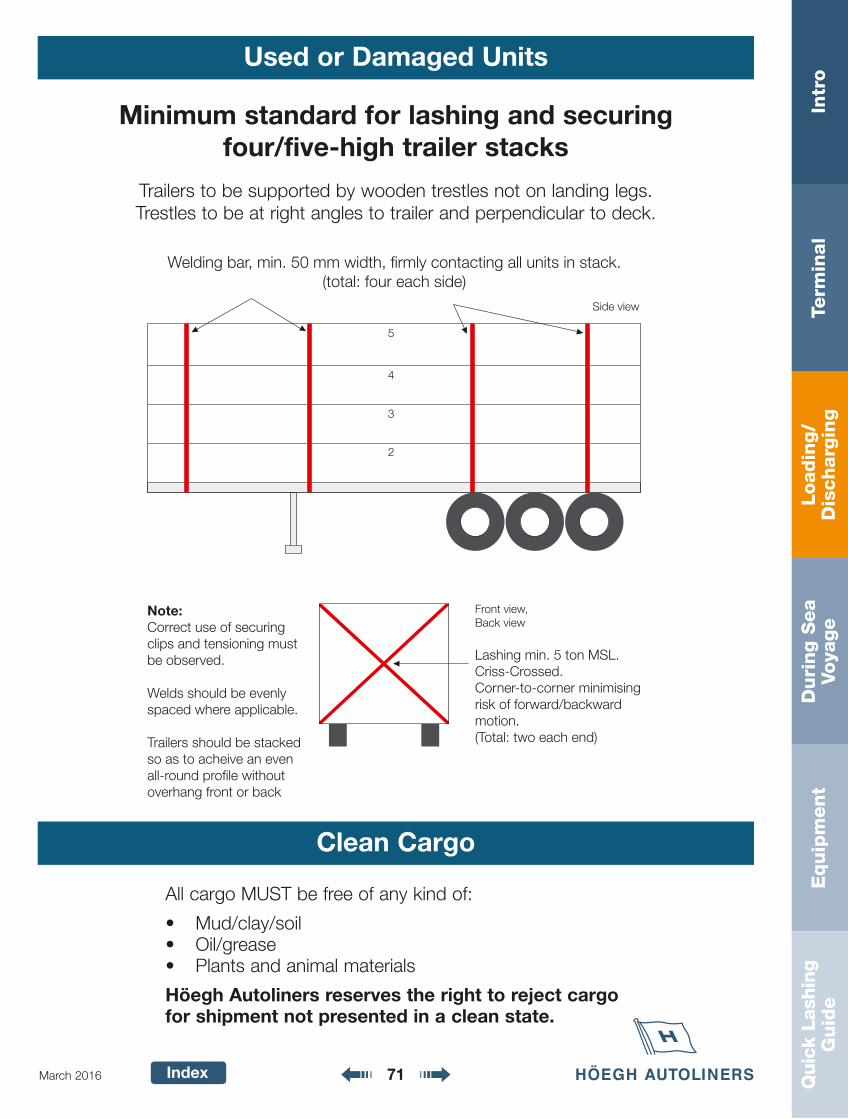
Minimum standard for lashing and securingfour/five-high trailer stacks
Welding bar, min. 50 mm width, firmly contacting all units in stack.(total: four each side)
Front view,Back view
Lashing min. 5 ton MSL. Criss-Crossed.Corner-to-corner minimising risk of forward/backward motion.(Total: two each end)
Note:Correct use of securing clips and tensioning must be observed.
Welds should be evenly spaced where applicable.
Trailers should be stacked so as to acheive an even all-round profile without overhang front or back
5
4
3
2
Side view
Trailers to be supported by wooden trestles not on landing legs.Trestles to be at right angles to trailer and perpendicular to deck.
Clean Cargo
All cargo MUST be free of any kind of:
• Mud/clay/soil• Oil/grease• Plants and animal materials
Höegh Autoliners reserves the right to reject cargo for shipment not presented in a clean state.
Loadin
g/
Dis
charg
ing
Intr
oTe
rmin
al
Duri
ng S
ea
Voya
ge
Equip
ment
Quic
k La
shin
gG
uid
e
Index 72March 2016
Short Sea/Feeder
RA
MP
RA
MP
= K
ey c
ars'
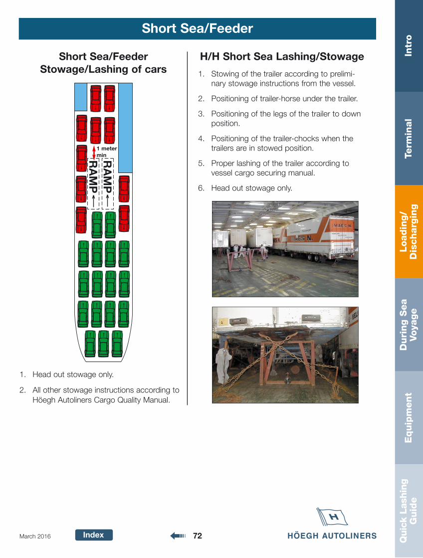
1 meter min
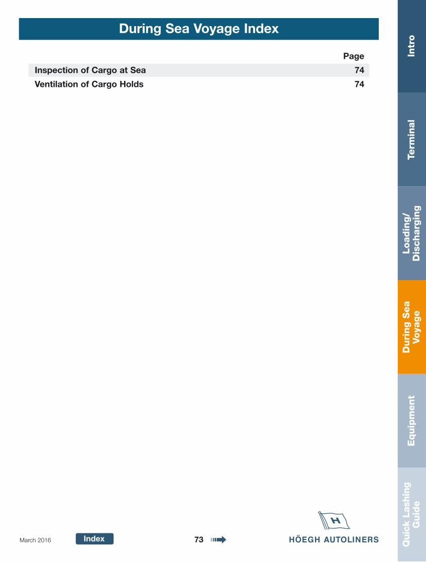
H/H Short Sea Lashing/Stowage
1. Stowing of the trailer according to prelimi-nary stowage instructions from the vessel.
2. Positioning of trailer-horse under the trailer.
3. Positioning of the legs of the trailer to downposition.
4. Positioning of the trailer-chocks when thetrailers are in stowed position.
5. Proper lashing of the trailer according tovessel cargo securing manual.
6. Head out stowage only.
1. Head out stowage only.
2. All other stowage instructions according toHöegh Autoliners Cargo Quality Manual.
Short Sea/Feeder Stowage/Lashing of cars
Duri
ng S
ea
Voya
ge
Intr
oTe
rmin
al
Loadin
g/
Dis
charg
ing
Equip
ment
Quic
k La
shin
gG
uid
e
Index 73March 2016
During Sea Voyage Index
Page
Inspection of Cargo at Sea 74
Ventilation of Cargo Holds 74
Duri
ng S
ea
Voya
ge
Intr
oTe
rmin
al
Loadin
g/
Dis
charg
ing
Equip
ment
Quic
k La
shin
gG
uid
e
Index 74March 2016
Inspection of Cargo at Sea
At SeaAfter cargo operation has been completed, ventilation shallbe run continuously till the cargo holds are proven gas-free.
When loading wet or snow covered cargo, ventilation shallbe run continuously till the cargo and cargo holds are dry.
Good seamanship and common sense shall be used whenoperating the ventilation system on board the vessel.
Ventilation of Cargo Holds
The following inspection routines shall apply after thevessels has left the load port:
The first 3 days after leaving the load port, inspections shalltake place daily.
Inspection shall continue with an interval of maximum 3 days, after the initial 3 days.
If encountering bad weather inspection shall be performedas long and often as necessary according to the judgementof the vessels command.
Lashings shall be tightened, corrected or added if needed,according to good seamanship.
The crew has a right to inspect cargo if they suspect that acargo unit can be dangerous to the vessel.
NB! All inspections and actions to be noted down inthe vessel’s deck log book.
Equip
ment
Intr
oTe
rmin
al
Loadin
g/
Dis
charg
ing
Duri
ng S
ea
Voya
ge
Quic
k La
shin
gG
uid
e
Index 75March 2016
Equipment Index
Page
Decklifter 76
Forklift 76
Volk Service Car 77
Deck Sweepers / Deck Cleaners 77
Terberg R323 Tugmaster (Horizon Class Vessels) 78
Höegh Autoliners Equipment 79-84
Höegh Autoliners Roll trailer Equipment 84
Höegh Autoliners Roll trailer Lashing 85-86
Port Hangers 87
Port Stickers 87
Information Stickers 88
Correct use of equipment, please see loading/discharging chapter
Instructions for maintenance of rolling equipment has been moved to Masters Manual.
For any query and request of equipment please send e-mail to:[email protected]
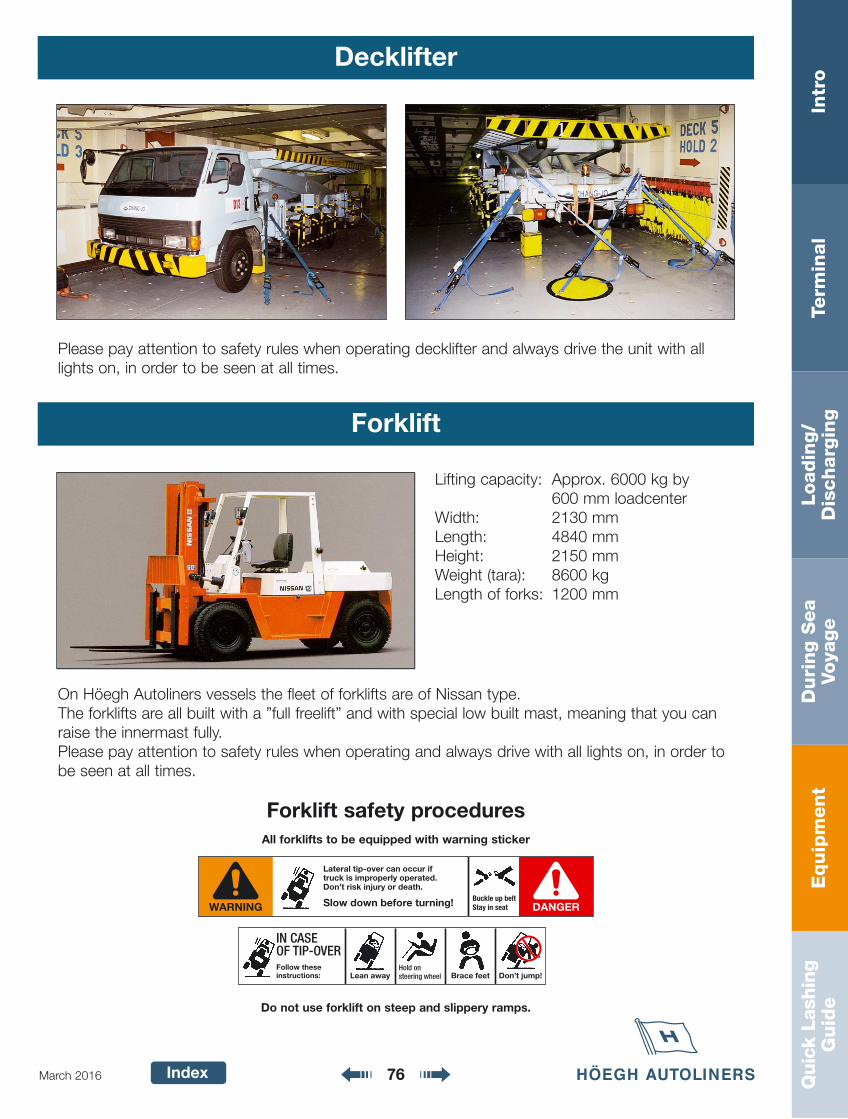
Equip
ment
Intr
oTe
rmin
al
Loadin
g/
Dis
charg
ing
Duri
ng S
ea
Voya
ge
Quic
k La
shin
gG
uid
e
Index 76March 2016
Decklifter
Forklift
Lifting capacity: Approx. 6000 kg by 600 mm loadcenter
Width: 2130 mmLength: 4840 mmHeight: 2150 mmWeight (tara): 8600 kgLength of forks: 1200 mm
On Höegh Autoliners vessels the fleet of forklifts are of Nissan type.The forklifts are all built with a ”full freelift” and with special low built mast, meaning that you canraise the innermast fully.Please pay attention to safety rules when operating and always drive with all lights on, in order tobe seen at all times.
Forklift safety proceduresAll forklifts to be equipped with warning sticker
Do not use forklift on steep and slippery ramps.
DANGERWARNINGBuckle up beltStay in seat
Lateral tip-over can occur iftruck is improperly operated.Don’t risk injury or death.
Slow down before turning!
Lean awayHold onsteering wheel Brace feet Don’t jump!
IN CASEOF TIP-OVERFollow theseinstructions:
Please pay attention to safety rules when operating decklifter and always drive the unit with alllights on, in order to be seen at all times.
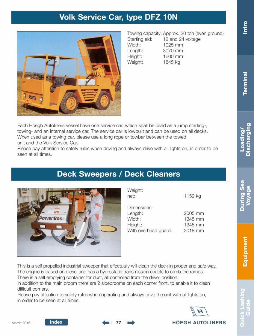
Equip
ment
Intr
oTe
rmin
al
Loadin
g/
Dis
charg
ing
Duri
ng S
ea
Voya
ge
Quic
k La
shin
gG
uid
e
Index 77March 2016
Volk Service Car, type DFZ 10N
Each Höegh Autoliners vessel have one service car, which shall be used as a jump starting-, towing- and an internal service car. The service car is lowbuilt and can be used on all decks.When used as a towing car, please use a long rope or towbar between the towedunit and the Volk Service Car.Please pay attention to safety rules when driving and always drive with all lights on, in order to beseen at all times.
Towing capacity: Approx. 20 ton (even ground)Starting aid: 12 and 24 voltageWidth: 1025 mmLength: 3070 mmHeight: 1600 mmWeight: 1845 kg
Deck Sweepers / Deck Cleaners
Weight:net: 1159 kg
Dimensions:Length: 2005 mmWidth: 1345 mmHeight: 1345 mmWith overhead guard: 2018 mm
This is a self propelled industrial sweeper that effectually will clean the deck in proper and safe way. The engine is based on diesel and has a hydrostatic transmission enable to climb the ramps. There is a self emptying container for dust, all controlled from the driver position.In addition to the main broom there are 2 sidebrooms on each corner front, to enable it to clean difficult corners.Please pay attention to safety rules when operating and always drive the unit with all lights on, in order to be seen at all times.
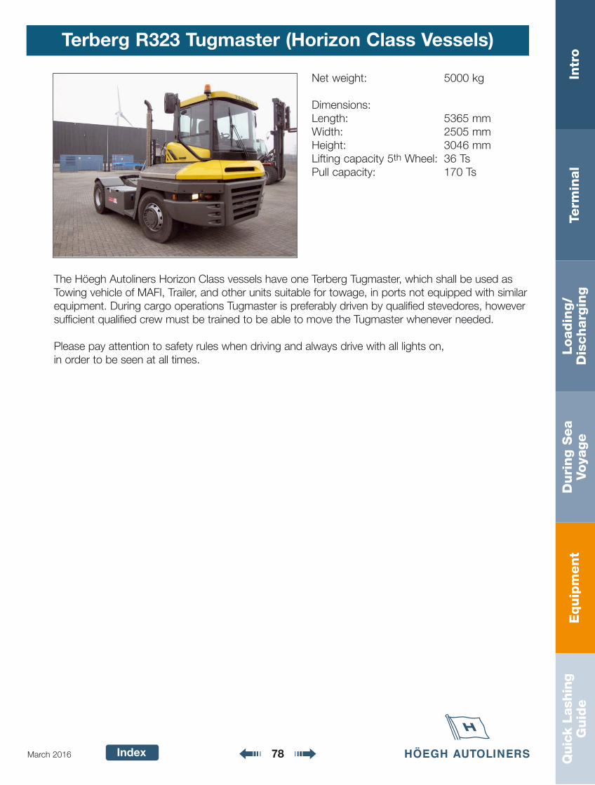
Equip
ment
Intr
oTe
rmin
al
Loadin
g/
Dis
charg
ing
Duri
ng S
ea
Voya
ge
Quic
k La
shin
gG
uid
e
Index 78March 2016
Terberg R323 Tugmaster (Horizon Class Vessels)
Net weight: 5000 kg
Dimensions:Length: 5365 mmWidth: 2505 mmHeight: 3046 mmLifting capacity 5th Wheel: 36 TsPull capacity: 170 Ts
The Höegh Autoliners Horizon Class vessels have one Terberg Tugmaster, which shall be used asTowing vehicle of MAFI, Trailer, and other units suitable for towage, in ports not equipped with similarequipment. During cargo operations Tugmaster is preferably driven by qualified stevedores, howeversufficient qualified crew must be trained to be able to move the Tugmaster whenever needed.
Please pay attention to safety rules when driving and always drive with all lights on, in order to be seen at all times.
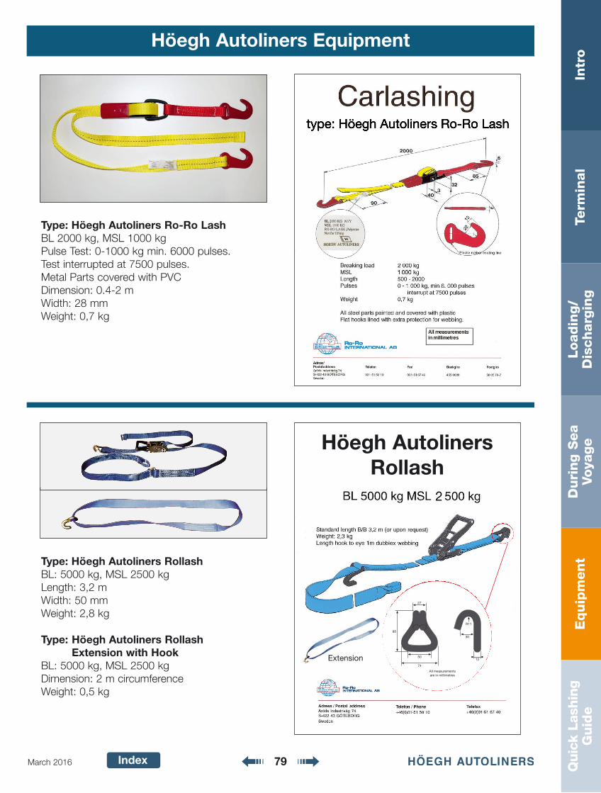
Equip
ment
Intr
oTe
rmin
al
Loadin
g/
Dis
charg
ing
Duri
ng S
ea
Voya
ge
Quic
k La
shin
gG
uid
e
Index 79March 2016
Höegh Autoliners Equipment
Type: Höegh Autoliners Ro-Ro LashBL 2000 kg, MSL 1000 kgPulse Test: 0-1000 kg min. 6000 pulses.Test interrupted at 7500 pulses.Metal Parts covered with PVCDimension: 0.4-2 mWidth: 28 mmWeight: 0,7 kg
Type: Höegh Autoliners RollashBL: 5000 kg, MSL 2500 kgLength: 3,2 mWidth: 50 mmWeight: 2,8 kg
Type: Höegh Autoliners Rollash Extension with Hook
BL: 5000 kg, MSL 2500 kgDimension: 2 m circumferenceWeight: 0,5 kg
Extension
Höegh AutolinersRollash
27
30
13
R11
50
74
All measurements are in millimetres
85
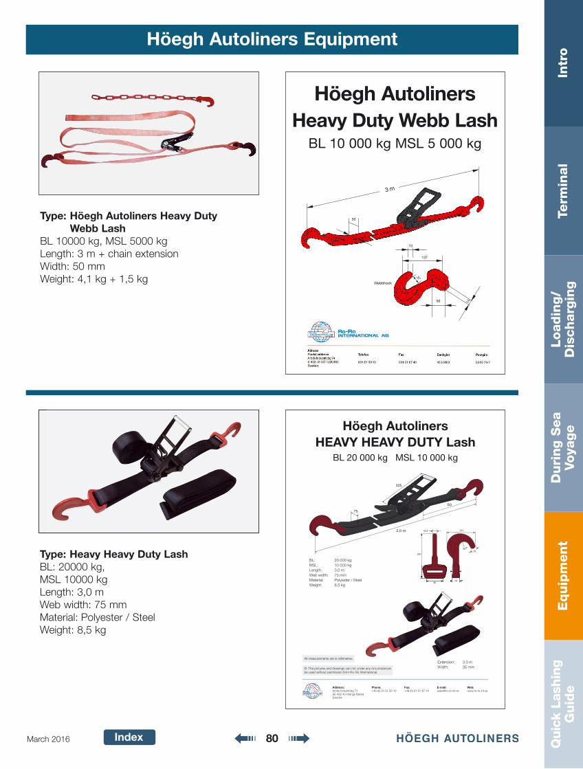
Equip
ment
Intr
oTe
rmin
al
Loadin
g/
Dis
charg
ing
Duri
ng S
ea
Voya
ge
Quic
k La
shin
gG
uid
e
Index 80March 2016
Höegh Autoliners Equipment
Type: Höegh Autoliners Heavy Duty Webb Lash
BL 10000 kg, MSL 5000 kgLength: 3 m + chain extensionWidth: 50 mmWeight: 4,1 kg + 1,5 kg
13
137
56 14
Webbhook
37
50
3 m
Höegh AutolinersHeavy Duty Webb Lash
BL 10 000 kg MSL 5 000 kg
Type: Heavy Heavy Duty LashBL: 20000 kg, MSL 10000 kgLength: 3,0 mWeb width: 75 mmMaterial: Polyester / SteelWeight: 8,5 kg
75
50
3,0 m
325
BL: 20 000 kg
MSL: 10 000 kg
Length: 3,0 m
Web width: 75 mm
Material: Polyester / Steel
Weight: 8,5 kg
Höegh AutolinersHEAVY HEAVY DUTY Lash
BL 20 000 kg MSL 10 000 kg
© The pictures and drawings can not under any circumstances be used without permission from Ro-Ro International.
All measurements are in millimetres
Address: Phone: Fax: E-mail: Web:Aröds Industriväg 74 +46 (0) 31-51 50 10 +46 (0) 31-51 67 40 [email protected] www.ro-ro-int.seSE-422 43 Hisings BackaSweden
50ø
80
200
16,5
34
27
131
25
8034
Extension: 3,0 m
Width: 35 mm
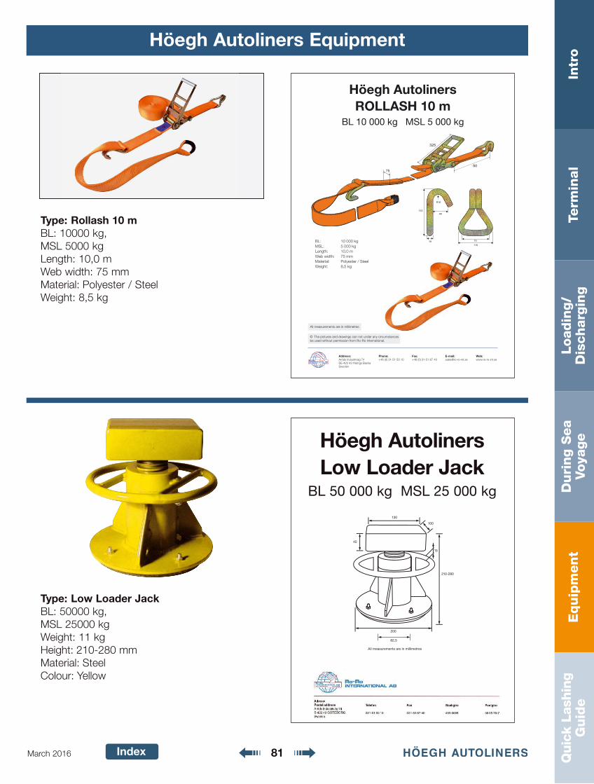
Equip
ment
Intr
oTe
rmin
al
Loadin
g/
Dis
charg
ing
Duri
ng S
ea
Voya
ge
Quic
k La
shin
gG
uid
e
Index 81March 2016
Höegh Autoliners Equipment
Type: Low Loader JackBL: 50000 kg, MSL 25000 kgWeight: 11 kgHeight: 210-280 mm Material: SteelColour: Yellow
Höegh AutolinersLow Loader Jack
BL 50 000 kg MSL 25 000 kg
200
15
130
45
100
82,5
210-280
All measurements are in millimetres
Type: Rollash 10 mBL: 10000 kg, MSL 5000 kgLength: 10,0 mWeb width: 75 mmMaterial: Polyester / SteelWeight: 8,5 kg
75
325
50
BL: 10 000 kg
MSL: 5 000 kg
Length: 10,0 m
Web width: 75 mm
Material: Polyester / Steel
Weight: 8,5 kg
Höegh AutolinersROLLASH 10 m
BL 10 000 kg MSL 5 000 kg
© The pictures and drawings can not under any circumstances be used without permission from Ro-Ro International.
All measurements are in millimetres
Address: Phone: Fax: E-mail: Web:Aröds Industriväg 74 +46 (0) 31-51 50 10 +46 (0) 31-51 67 40 [email protected] www.ro-ro-int.seSE-422 43 Hisings BackaSweden
R16
40133
110
7518
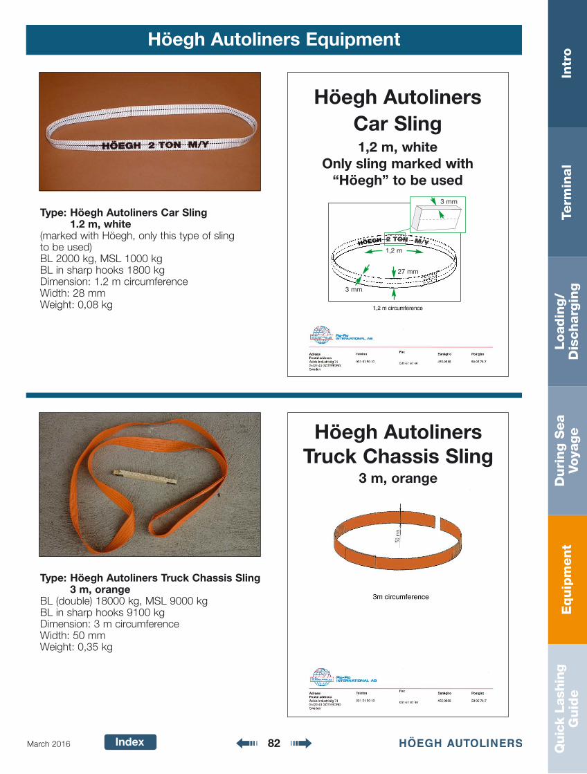
Equip
ment
Intr
oTe
rmin
al
Loadin
g/
Dis
charg
ing
Duri
ng S
ea
Voya
ge
Quic
k La
shin
gG
uid
e
Index 82March 2016
Höegh Autoliners Equipment
Type: Höegh Autoliners Car Sling 1.2 m, white
(marked with Höegh, only this type of sling to be used)BL 2000 kg, MSL 1000 kgBL in sharp hooks 1800 kgDimension: 1.2 m circumferenceWidth: 28 mmWeight: 0,08 kg
Höegh AutolinersCar Sling1,2 m, white
Only sling marked with “Höegh” to be used
Type: Höegh Autoliners Truck Chassis Sling 3 m, orange
BL (double) 18000 kg, MSL 9000 kgBL in sharp hooks 9100 kgDimension: 3 m circumferenceWidth: 50 mmWeight: 0,35 kg
Höegh AutolinersTruck Chassis Sling
3 m, orange
1,2 m
27 mm
3 mm
3 mm
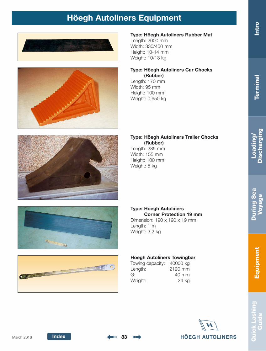
Equip
ment
Intr
oTe
rmin
al
Loadin
g/
Dis
charg
ing
Duri
ng S
ea
Voya
ge
Quic
k La
shin
gG
uid
e
Index 83March 2016
Höegh Autoliners Equipment
Höegh Autoliners TowingbarTowing capacity: 40000 kgLength: 2120 mmØ: 40 mmWeight: 24 kg
Type: Höegh AutolinersCorner Protection 19 mm
Dimension: 190 x 190 x 19 mmLength: 1 mWeight: 3,2 kg
Type: Höegh Autoliners Car Chocks (Rubber)
Length: 170 mmWidth: 95 mmHeight: 100 mmWeight: 0,650 kg
Type: Höegh Autoliners Trailer Chocks (Rubber)
Length: 285 mmWidth: 155 mmHeight: 100 mmWeight: 5 kg
Type: Höegh Autoliners Rubber MatLength: 2000 mmWidth: 330/400 mmHeight: 10-14 mmWeight: 10/13 kg
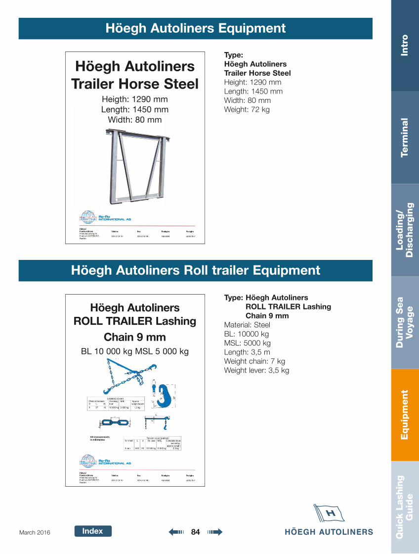
Equip
ment
Intr
oTe
rmin
al
Loadin
g/
Dis
charg
ing
Duri
ng S
ea
Voya
ge
Quic
k La
shin
gG
uid
e
Index 84March 2016
Höegh Autoliners Equipment
Type: Höegh AutolinersROLL TRAILER LashingChain 9 mm
Material: SteelBL: 10000 kgMSL: 5000 kgLength: 3,5 mWeight chain: 7 kgWeight lever: 3,5 kg
Höegh AutolinersROLL TRAILER Lashing
Chain 9 mmBL 10 000 kg MSL 5 000 kg
Höegh Autoliners Roll trailer Equipment
Type: Höegh AutolinersTrailer Horse SteelHeight: 1290 mmLength: 1450 mmWidth: 80 mmWeight: 72 kg
Höegh AutolinersTrailer Horse Steel
Heigth: 1290 mmLength: 1450 mm
Width: 80 mm
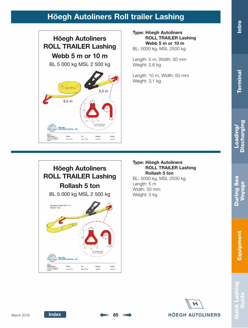
Equip
ment
Intr
oTe
rmin
al
Loadin
g/
Dis
charg
ing
Duri
ng S
ea
Voya
ge
Quic
k La
shin
gG
uid
e
Index 85March 2016
Höegh Autoliners Roll trailer Lashing
Type: Höegh AutolinersROLL TRAILER Lashing Webb 5 m or 10 m
BL: 5000 kg, MSL 2500 kg
Length: 5 m, Width: 50 mmWeight: 2,6 kg
Length: 10 m, Width: 50 mmWeight: 3,1 kg
9,5 m
0,5 m
Höegh AutolinersROLL TRAILER Lashing
Webb 5 m or 10 mBL 5 000 kg MSL 2 500 kg
Type: Höegh AutolinersROLL TRAILER Lashing Rollash 5 ton
BL: 5000 kg, MSL 2500 kgLength: 5 mWidth: 50 mmWeight: 3 kg
Höegh AutolinersROLL TRAILER Lashing
Rollash 5 tonBL 5 000 kg MSL 2 500 kg
Standard length B/B: 5 mWeight: 3 kg
28
38
14
R13,5
51
76
88
All measurements are in millimetres
28
38
14
R13,5
51
76
88
All measurements are in millimetres
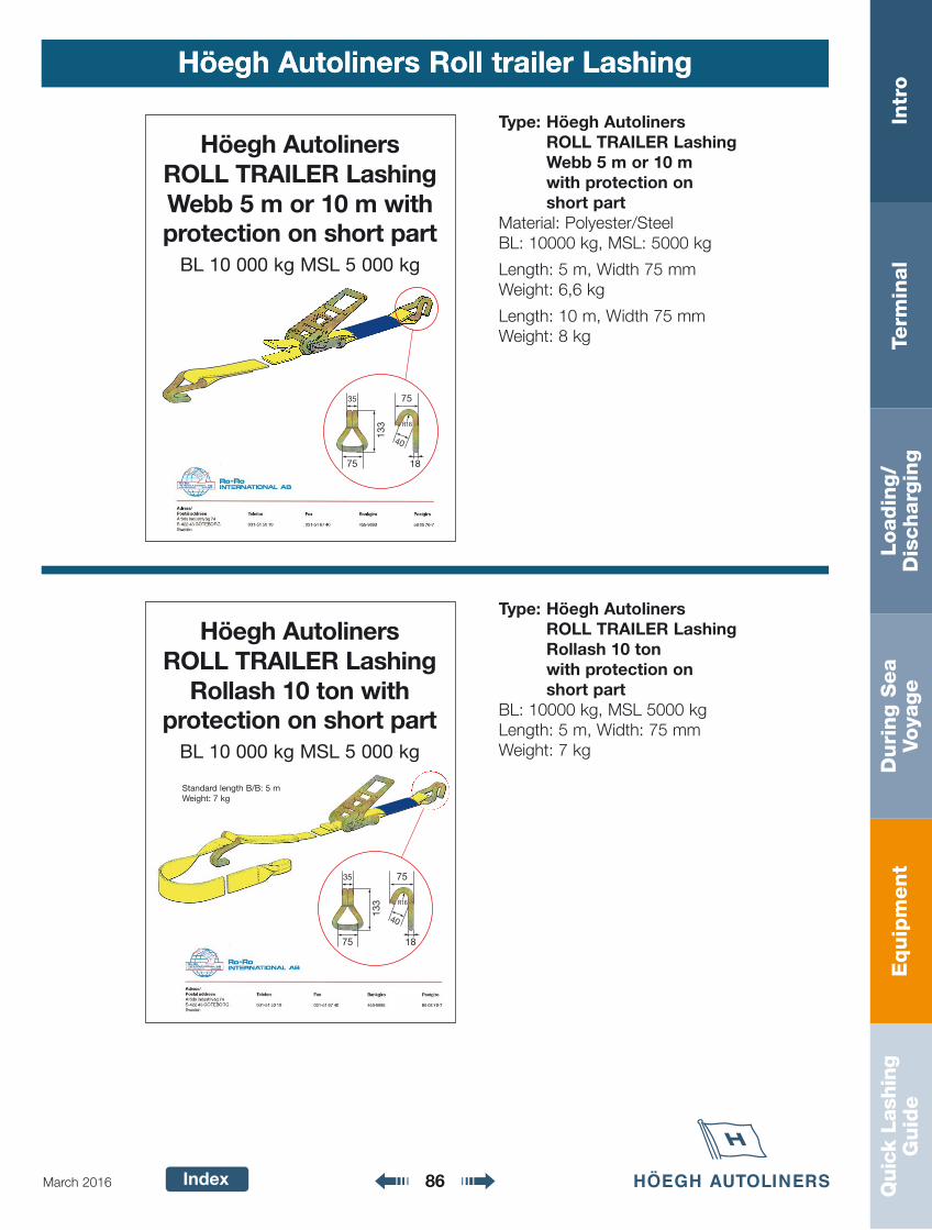
Equip
ment
Intr
oTe
rmin
al
Loadin
g/
Dis
charg
ing
Duri
ng S
ea
Voya
ge
Quic
k La
shin
gG
uid
e
Index 86March 2016
Höegh Autoliners Roll trailer LashingHöegh Autoliners Roll trailer Lashing
Type: Höegh AutolinersROLL TRAILER LashingWebb 5 m or 10 mwith protection on short part
Material: Polyester/SteelBL: 10000 kg, MSL: 5000 kg
Length: 5 m, Width 75 mmWeight: 6,6 kg
Length: 10 m, Width 75 mmWeight: 8 kg
133
75
35
18
R16
75
40
Höegh AutolinersROLL TRAILER Lashing Webb 5 m or 10 m with protection on short part
BL 10 000 kg MSL 5 000 kg
Type: Höegh AutolinersROLL TRAILER Lashing Rollash 10 tonwith protection on short part
BL: 10000 kg, MSL 5000 kgLength: 5 m, Width: 75 mmWeight: 7 kg
Höegh AutolinersROLL TRAILER Lashing
Rollash 10 ton with protection on short part
BL 10 000 kg MSL 5 000 kg
Standard length B/B: 5 mWeight: 7 kg
133
75
35
18
R16
75
40
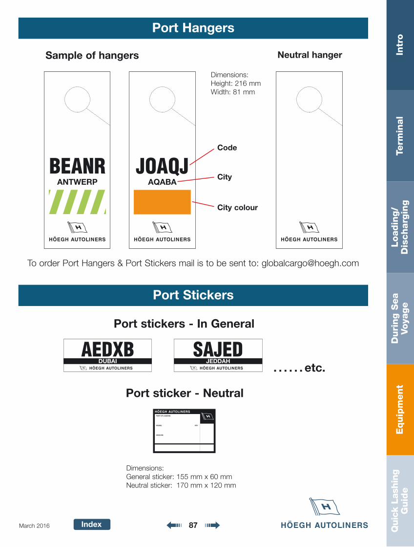
Equip
ment
Intr
oTe
rmin
al
Loadin
g/
Dis
charg
ing
Duri
ng S
ea
Voya
ge
Quic
k La
shin
gG
uid
e
Index 87March 2016
Port Hangers
BEANRANTWERP
JOAQJAQABA
Code
City
City colour
Sample of hangers Neutral hanger
Port stickers - In General
AEDXBDUBAI
SAJEDJEDDAH
. . . . . . etc.
PORT OF LOADING
VESSEL VOY
CHAS.NO.
Port sticker - Neutral
Port Stickers
Dimensions:Height: 216 mmWidth: 81 mm
Dimensions:General sticker: 155 mm x 60 mmNeutral sticker: 170 mm x 120 mm
To order Port Hangers & Port Stickers mail is to be sent to: [email protected]
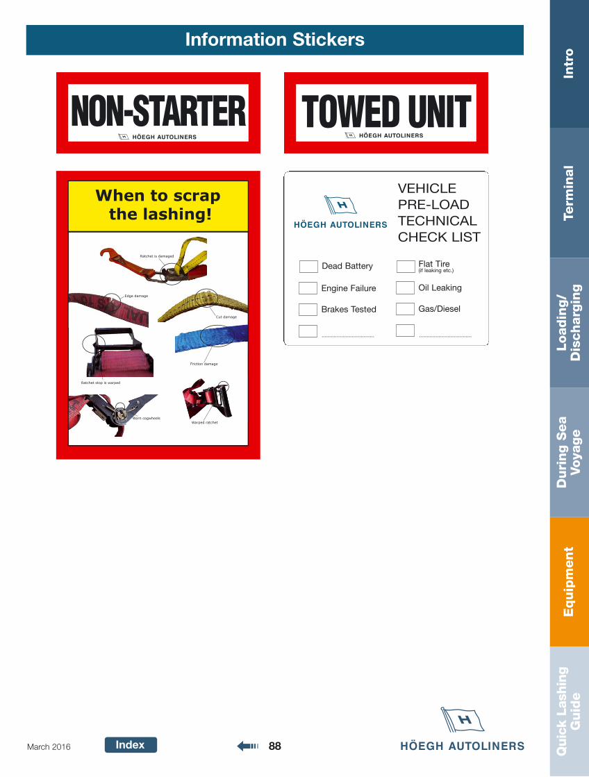
Equip
ment
Intr
oTe
rmin
al
Loadin
g/
Dis
charg
ing
Duri
ng S
ea
Voya
ge
Quic
k La
shin
gG
uid
e
Index 88March 2016
Information Stickers
NON-STARTER TOWED UNIT
VEHICLE
PRE-LOAD
TECHNICAL
CHECK LIST
Dead Battery Flat Tire(if leaking etc.)
Engine Failure Oil Leaking
Brakes Tested Gas/Diesel
......................................................................
Friction damage
Warped ratchet
Ratchet stop is warped
Cut damage
Worn cogwheels
Edge damage
When to scrap the lashing!
Ratchet is damaged
Quic
k La
shin
gG
uid
eIn
tro
Term
inal
Loadin
g/
Dis
charg
ing
Duri
ng S
ea
Voya
ge
Equip
ment
Index 89March 2016
Quick Lashing Guide
Page
Quick Lashing Guide – Sea Area C 90
Cargo Securing Methods 91-93
Basic Cargo Securing Requirements 94
Sliding - Friction 95
Tipping - Dimensions 96
Lashing Eyes 97
Conversion Factors 97
Required Number Of Lashings 98-111
Wandering 99
Cargo stowed in more than one layer 99
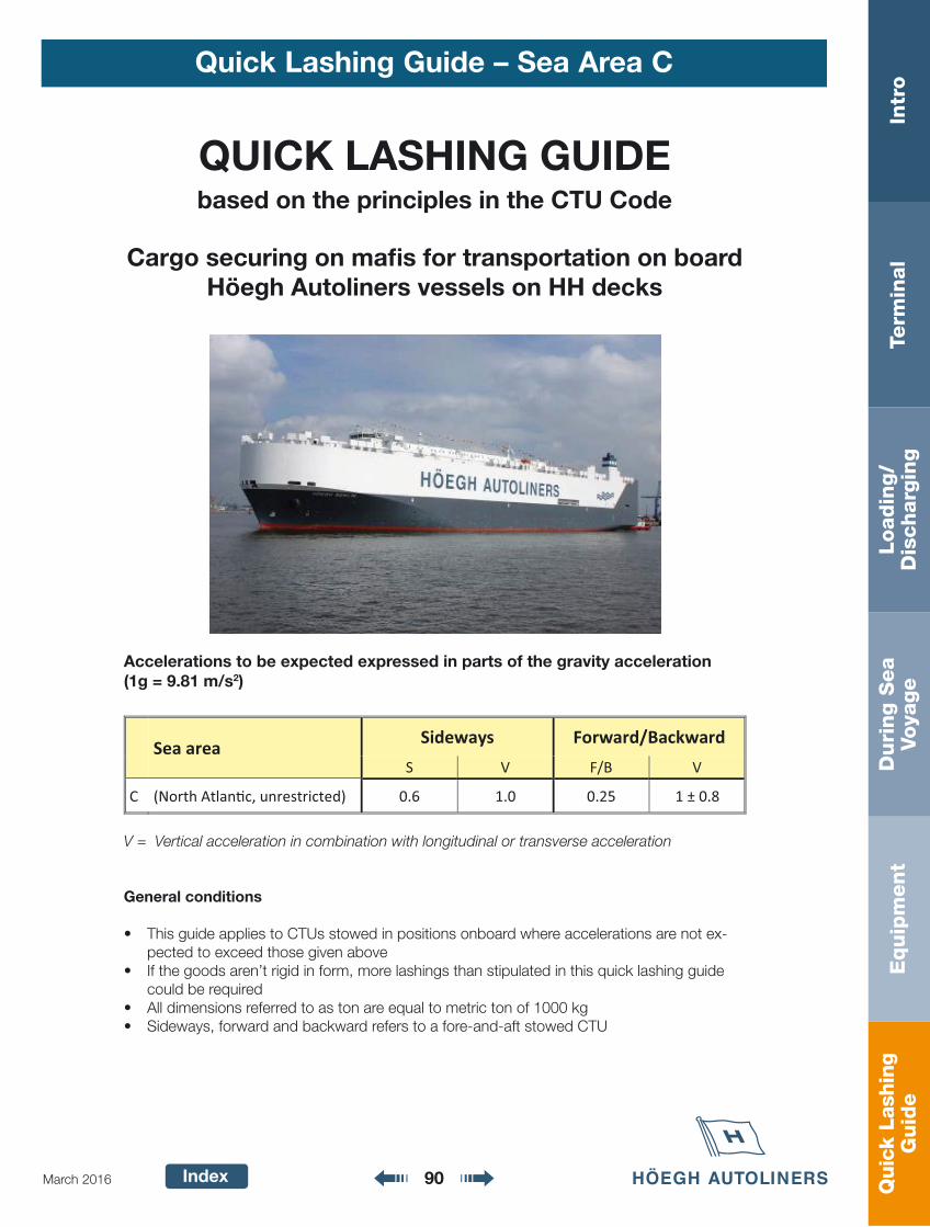
Quic
k La
shin
gG
uid
eIn
tro
Term
inal
Loadin
g/
Dis
charg
ing
Duri
ng S
ea
Voya
ge
Equip
ment
Index 90March 2016
Quick Lashing Guide – Sea Area C
QUICK LASHING GUIDEbased on the principles in the CTU Code
Cargo securing on mafi s for transportation on boardHöegh Autoliners vessels on HH decks
Accelerations to be expected expressed in parts of the gravity acceleration(1g = 9.81 m/s2)
V = Vertical acceleration in combination with longitudinal or transverse acceleration
General conditions
• This guide applies to CTUs stowed in positions onboard where accelerations are not ex-pected to exceed those given above
• If the goods aren’t rigid in form, more lashings than stipulated in this quick lashing guide could be required
• All dimensions referred to as ton are equal to metric ton of 1000 kg• Sideways, forward and backward refers to a fore-and-aft stowed CTU
Sea area Sideways Forward/Backward
S V F/B V
C (North Atlan�c, unrestricted) 0.6 1.0 0.25 1 ± 0.8
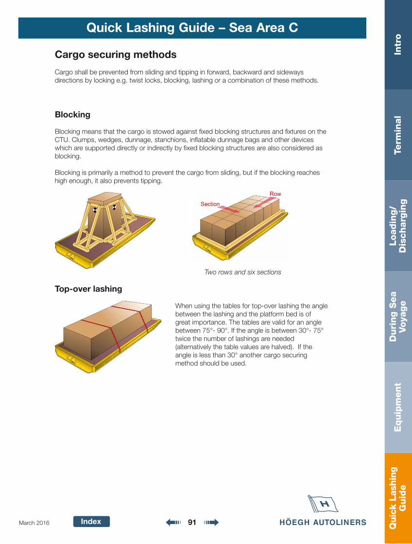
Quic
k La
shin
gG
uid
eIn
tro
Term
inal
Loadin
g/
Dis
charg
ing
Duri
ng S
ea
Voya
ge
Equip
ment
Index 91March 2016
Quick Lashing Guide – Sea Area C
Cargo securing methods
Cargo shall be prevented from sliding and tipping in forward, backward and sideways directions by locking e.g. twist locks, blocking, lashing or a combination of these methods.
Blocking
Blocking means that the cargo is stowed against fi xed blocking structures and fi xtures on theCTU. Clumps, wedges, dunnage, stanchions, infl atable dunnage bags and other devices which are supported directly or indirectly by fi xed blocking structures are also considered as blocking.
Blocking is primarily a method to prevent the cargo from sliding, but if the blocking reaches high enough, it also prevents tipping.
Top-over lashing
When using the tables for top-over lashing the angle between the lashing and the platform bed is of great importance. The tables are valid for an angle between 75°- 90°. If the angle is between 30°- 75° twice the number of lashings are needed (alternatively the table values are halved). If the angle is less than 30° another cargo securing method should be used.
Two rows and six sections
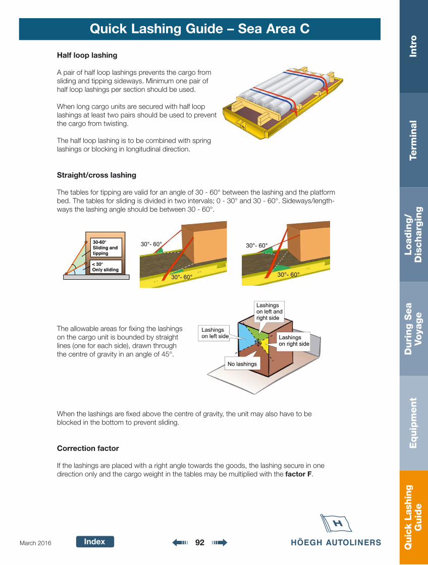
Quic
k La
shin
gG
uid
eIn
tro
Term
inal
Loadin
g/
Dis
charg
ing
Duri
ng S
ea
Voya
ge
Equip
ment
Index 92March 2016
Quick Lashing Guide – Sea Area C
Half loop lashing
A pair of half loop lashings prevents the cargo from sliding and tipping sideways. Minimum one pair of half loop lashings per section should be used.
When long cargo units are secured with half loop lashings at least two pairs should be used to prevent the cargo from twisting.
The half loop lashing is to be combined with spring lashings or blocking in longitudinal direction.
Straight/cross lashing
The tables for tipping are valid for an angle of 30 - 60° between the lashing and the platform bed. The tables for sliding is divided in two intervals; 0 - 30° and 30 - 60°. Sideways/length- ways the lashing angle should be between 30 - 60°.
The allowable areas for fi xing the lashings on the cargo unit is bounded by straight lines (one for each side), drawn through the centre of gravity in an angle of 45°.
When the lashings are fi xed above the centre of gravity, the unit may also have to be blocked in the bottom to prevent sliding.
Correction factor
If the lashings are placed with a right angle towards the goods, the lashing secure in one direction only and the cargo weight in the tables may be multiplied with the factor F.
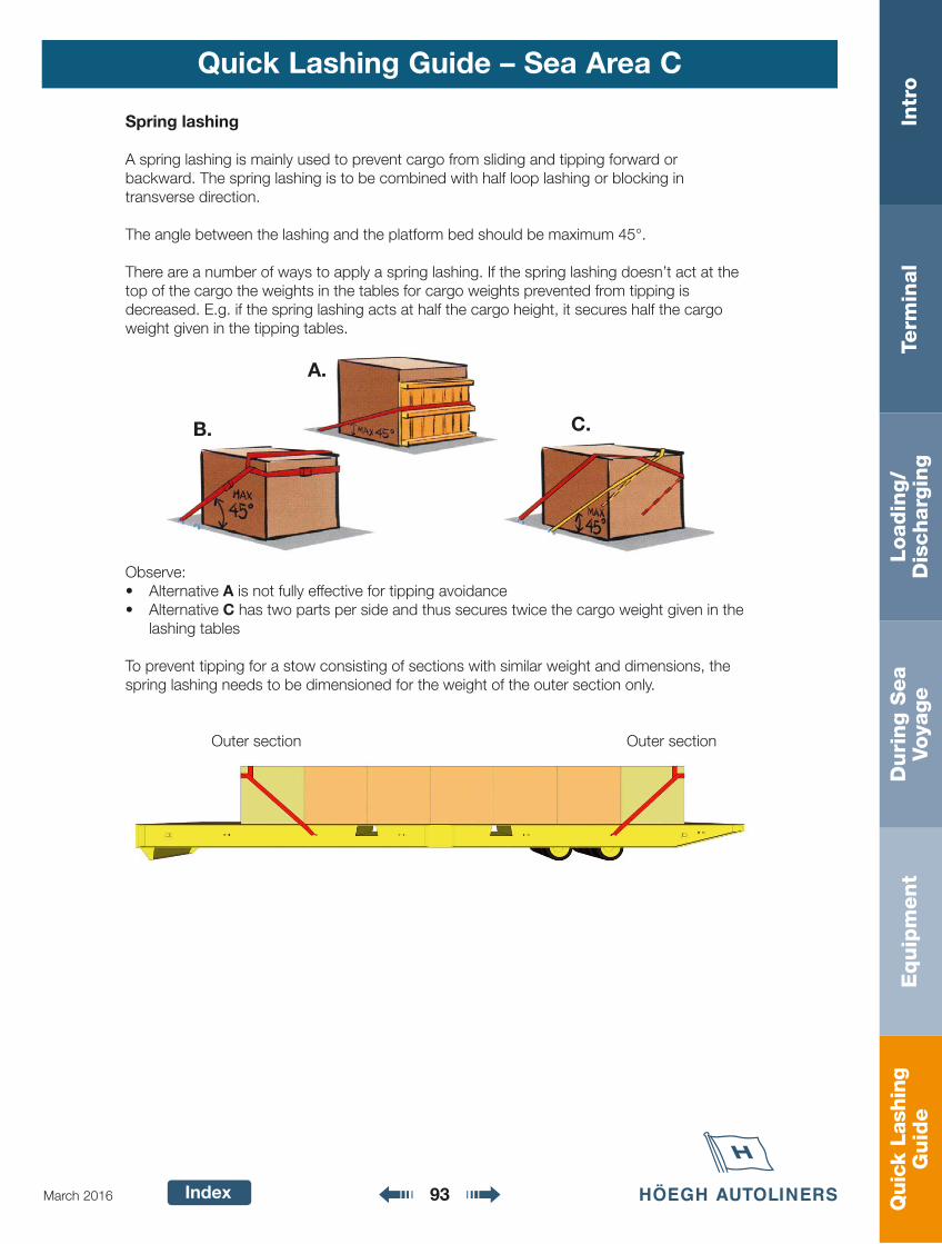
Quic
k La
shin
gG
uid
eIn
tro
Term
inal
Loadin
g/
Dis
charg
ing
Duri
ng S
ea
Voya
ge
Equip
ment
Index 93March 2016
Quick Lashing Guide – Sea Area C
A.
B. C.
Spring lashing
A spring lashing is mainly used to prevent cargo from sliding and tipping forward or backward. The spring lashing is to be combined with half loop lashing or blocking in transverse direction.
The angle between the lashing and the platform bed should be maximum 45°.
There are a number of ways to apply a spring lashing. If the spring lashing doesn’t act at the top of the cargo the weights in the tables for cargo weights prevented from tipping is decreased. E.g. if the spring lashing acts at half the cargo height, it secures half the cargo weight given in the tipping tables.
Observe:• Alternative A is not fully effective for tipping avoidance• Alternative C has two parts per side and thus secures twice the cargo weight given in the
lashing tables
To prevent tipping for a stow consisting of sections with similar weight and dimensions, the spring lashing needs to be dimensioned for the weight of the outer section only.
Outer section Outer section
Quic
k La
shin
gG
uid
eIn
tro
Term
inal
Loadin
g/
Dis
charg
ing
Duri
ng S
ea
Voya
ge
Equip
ment
Index 94March 2016
Quick Lashing Guide – Sea Area C
Basic cargo securing requirements
Non-rigid goods
If the goods are not rigid in form (bags, bales etc.) more lashings than prescribed in this quick lashing guide may be needed.
Rolling units
If rolling units aren’t blocked, chocks with a height of at least1/3 of the radius, maximum 20 cm, shall be used.
The units are in addition to be secured according to the lashingtables in this quick lashing guide.
Bottom blocking
Bottom blocking preventing cargo from sliding must have a height of at least 5 cm. Lashings must be used to prevent the cargo from tipping and from climbing over the blocking. Bottom blocking to the fl oor should not be done unless agreed with Höegh Global Cargo Services.
Nailing and welding
Nailing and welding to the fl oor should not be done unless agreed with Höegh Global Cargo Services.
Supporting edge beam
In some cases fewer lashings are needed than the number of sections that are to be secured. Since each unit has to be secured, the lashing effect may in these cases be spread out by supporting edge beams. For each end section one lashing shall be used as well as at least one lashing per every other section.
These edge beams can be manufactured profi les or deals (minimum 25×100 mm) nailed together.
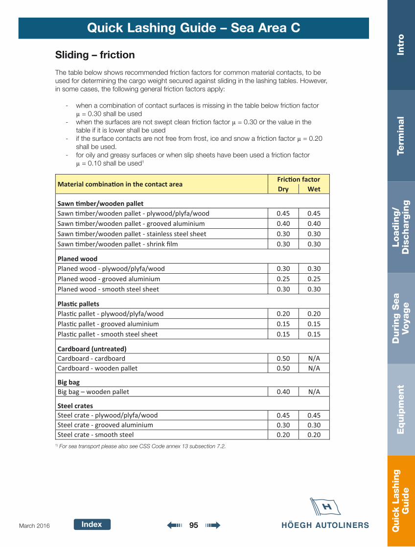
Quic
k La
shin
gG
uid
eIn
tro
Term
inal
Loadin
g/
Dis
charg
ing
Duri
ng S
ea
Voya
ge
Equip
ment
Index 95March 2016
Quick Lashing Guide – Sea Area C
Sliding – friction
The table below shows recommended friction factors for common material contacts, to be used for determining the cargo weight secured against sliding in the lashing tables. However, in some cases, the following general friction factors apply:
- when a combination of contact surfaces is missing in the table below friction factor = 0.30 shall be used- when the surfaces are not swept clean friction factor = 0.30 or the value in the
table if it is lower shall be used- if the surface contacts are not free from frost, ice and snow a friction factor = 0.20
shall be used.- for oily and greasy surfaces or when slip sheets have been used a friction factor = 0.10 shall be used1
1) For sea transport please also see CSS Code annex 13 subsection 7.2.
Material combina�on in the contact area Fric�on factor Dry Wet
Sawn �mber/wooden pallet Sawn �mber/wooden pallet - plywood/plyfa/wood 0.45 0.45 Sawn �mber/wooden pallet - grooved aluminium 0.40 0.40 Sawn �mber/wooden pallet - stainless steel sheet 0.30 0.30 Sawn �mber/wooden pallet - shrink film 0.30 0.30
Planed wood
Planed wood - plywood/plyfa/wood 0.30 0.30 Planed wood - grooved aluminium 0.25 0.25 Planed wood - smooth steel sheet 0.30 0.30
Plas�c pallets Plas�c pallet - plywood/plyfa/wood 0.20 0.20 Plas�c pallet - grooved aluminium 0.15 0.15 Plas�c pallet - smooth steel sheet 0.15 0.15
Cardboard (untreated) Cardboard - cardboard 0.50 N/ACardboard - wooden pallet 0.50 N/A
Big bag Big bag – wooden pallet 0.40 N/A
Steel crates
Steel crate - plywood/plyfa/wood 0.45 0.45 Steel crate - grooved aluminium 0.30 0.30 Steel crate - smooth steel 0.20 0.20
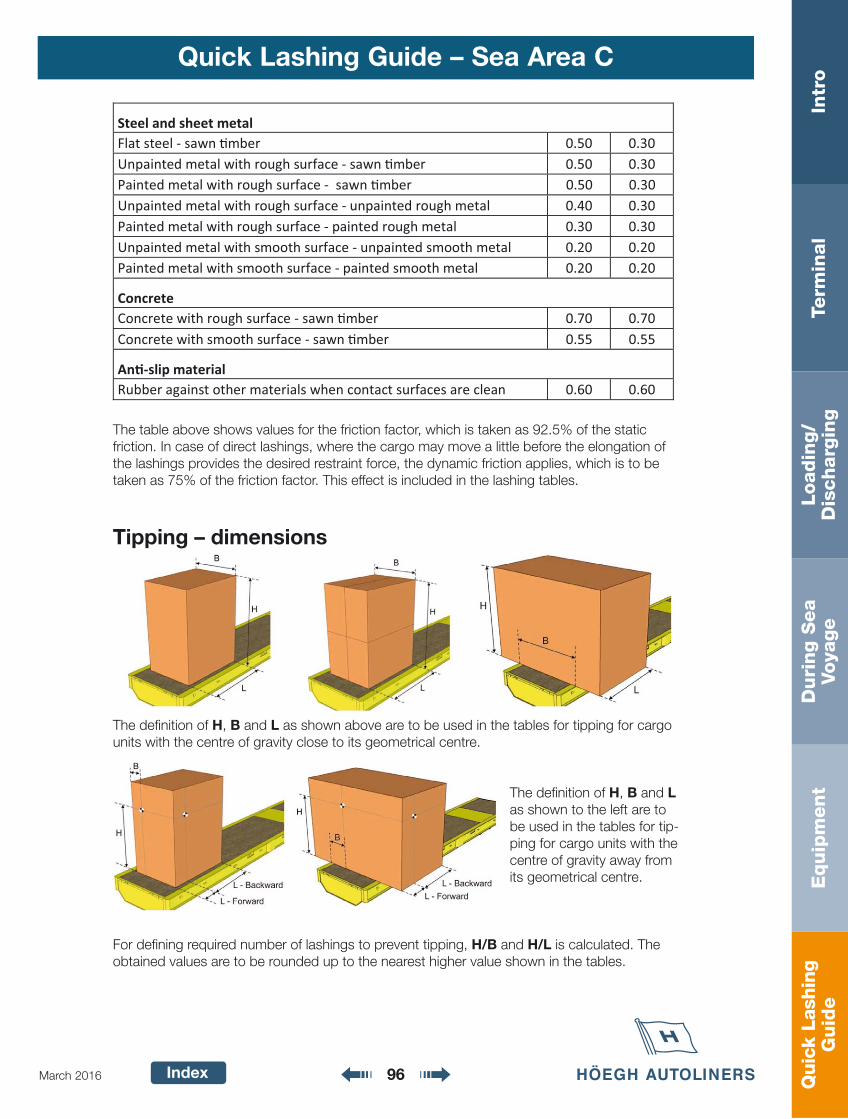
Quic
k La
shin
gG
uid
eIn
tro
Term
inal
Loadin
g/
Dis
charg
ing
Duri
ng S
ea
Voya
ge
Equip
ment
Index 96March 2016
Quick Lashing Guide – Sea Area C
The table above shows values for the friction factor, which is taken as 92.5% of the static friction. In case of direct lashings, where the cargo may move a little before the elongation of the lashings provides the desired restraint force, the dynamic friction applies, which is to be taken as 75% of the friction factor. This effect is included in the lashing tables.
Tipping – dimensions
The defi nition of H, B and L as shown above are to be used in the tables for tipping for cargo units with the centre of gravity close to its geometrical centre.
The defi nition of H, B and L as shown to the left are to be used in the tables for tip-ping for cargo units with the centre of gravity away from its geometrical centre.
For defi ning required number of lashings to prevent tipping, H/B and H/L is calculated. The obtained values are to be rounded up to the nearest higher value shown in the tables.
Steel and sheet metal Flat steel - sawn �mber 0.50 0.30 Unpainted metal with rough surface - sawn �mber 0.50 0.30 Painted metal with rough surface - sawn �mber 0.50 0.30 Unpainted metal with rough surface - unpainted rough metal 0.40 0.30 Painted metal with rough surface - painted rough metal 0.30 0.30 Unpainted metal with smooth surface - unpainted smooth metal 0.20 0.20 Painted metal with smooth surface - painted smooth metal 0.20 0.20
Concrete Concrete with rough surface - sawn �mber 0.70 0.70 Concrete with smooth surface - sawn �mber 0.55 0.55
An�-slip material Rubber against other materials when contact surfaces are clean 0.60 0.60

Quic
k La
shin
gG
uid
eIn
tro
Term
inal
Loadin
g/
Dis
charg
ing
Duri
ng S
ea
Voya
ge
Equip
ment
Index 97March 2016
Quick Lashing Guide – Sea Area C
Lashing eyes
The lashing eyes should have at least the same strength in MSL as the lashings. For a half loop lashing the lashing eye should have at least the strength of 1.4×MSL of the lashing if both ends of the lashing are fi xed to the same eye.
Conversion factors
For lashing equipment with MSL and pre-tension other than those shown in tables in this quick lashing guide, the table values shall be multiplied by a conversion factor corresponding to the actual lashing method and type of equipment, see the table below. All values used should be taken in daN, where 1 daN 1 kg.
2) Pre-tension and MSL are the values for the lashing equipment intended to be used
Example: How many tons of cargo is prevented from sliding sideways by a pair of half loop web lashings with MSL 4 ton, if the friction factor is 0.3?
According to the quick lashing guide a pair of half loop web lashings with MSL 2500 daN prevents 8.2 ton of cargo from sliding sideways when the friction factor is 0.3.
MSL for the current web lashing is 4 ton 4000 daN.
According to the table above, the conversion factor for half loop lashings is; MSL/2500 =4000/2500 = 1.6. The cargo weight prevented from sliding according to the lashing table shall be multiplied by the conversion factor and each pair of half loop web lashings thus prevents 1.6 × 8.2 = 13.1 ton of cargo from sliding sideways.
Lashing method Webbing 5 ton Webbing 10 ton Chain
Top-over lashing
Pre-tension2/500
Pre-tension2/500
Pre-tension2/1000
Half loop lashing
Spring lashing
MSL2/2500 MSL2/5000 MSL2/5000
Straight lashing
Quic
k La
shin
gG
uid
eIn
tro
Term
inal
Loadin
g/
Dis
charg
ing
Duri
ng S
ea
Voya
ge
Equip
ment
Index 98March 2016
Quick Lashing Guide – Sea Area C
Required number of lashings
The lashings tables in this quick lashing guide show the cargo weight in ton (1000 kg) prevented from sliding or tipping per lashing. The values in the tables are rounded to two signifi cant fi gures.
Top-over lashings
The required number of top-over lashings to prevent sliding and tipping is calculated by the help of the tables on page 100, 104 or 108 according to the following procedure:
1. Find out the actual friction factor2. Calculate the required number of top-over lashings to prevent sliding in all directions3. Calculate H/B, number of rows and H/L4. Calculate the required number of top-over lashings to prevent tipping in all directions5. The largest number of the above is selected
If the required number of top-over lashings is practically too many there are mainly two alternatives:1. Try to at least bottom block the cargo in the critical direction or increase the friction to
prevent sliding2. Use another lashing method – half loop or straight lashings in sideways direction and
spring or straight lashings in lengthways direction
Half loop lashings
The required number of half loop lashings to prevent sliding and tipping is calculated by the help of the tables on page 101, 105 or 109 according to the following procedure:
1. Find out the actual friction factor2. Calculate the required number of half loop lashings to prevent sliding sideways3. Calculate H/B and number of rows4. Calculate the required number of half loop lashings to prevent tipping sideways5. The largest number of the above is selected
Straight/cross lashings
The required number of straight/cross lashings to prevent sliding and tipping is calculated by the help of the tables on page 102, 106 or 110 according to the following procedure:
1. Find out the actual friction factor2. If the lashings are drawn in a straight angle towards the cargo, they secure the cargo in
one direction only and the f-factor shall be applied, see page 933. Calculate the required number of straight/cross lashings to prevent sliding in all
directions4. Calculate H/B, number of rows and H/L5. Calculate the required number of straight/cross lashings to prevent tipping in all
directions6. The largest number of the above is selected
Quic
k La
shin
gG
uid
eIn
tro
Term
inal
Loadin
g/
Dis
charg
ing
Duri
ng S
ea
Voya
ge
Equip
ment
Index 99March 2016
Quick Lashing Guide – Sea Area C
Spring lashingsThe required number of spring lashings to prevent sliding and tipping is calculated by the help of the tables on page 103, 107 or 111 according to the following procedure:
1. Find out the actual friction factor2. Calculate the required number of spring lashings to prevent sliding forward and backward3. Calculate H/L4. Calculate the required number of spring lashings to prevent tipping forward and backward5. The largest number of the above is selected
Wandering
Even if there is neither sliding nor tipping risk, it is recommended to always use at least;- 4 straight/cross lashings or- one top-over web lashing per every 5 ton of cargo or- one top-over chain lashing per every 10 ton of cargo
to avoid wandering for non-blocked cargo.
Cargo stowed in more than one layer
Methods to be used when calculating the number of required top-over lashings for cargo stowed in more than one layer.
Method 1 (simple):1. Determine the number of lashings to prevent sliding using
the weight of the entire section and the lowest friction of any of the layers.2. Determine the number of lashings to prevent tipping.3. The largest number of lashings in step 1 and 2 is to be used.
Method 2 (advanced):1. Determine the number of lashings to prevent sliding using the weight of the entire section
and the friction for the bottom layer.2. Determine the number of lashings to prevent sliding using the weight of the section’s
upper layer and the friction between the layers.3. Determine the number of lashings for the entire section which is required to prevent
tipping.4. The largest number of lashings in step 1 to 3 is to be used.
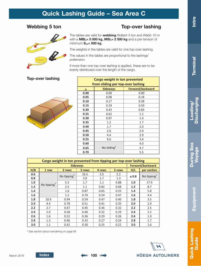
Quic
k La
shin
gG
uid
eIn
tro
Term
inal
Loadin
g/
Dis
charg
ing
Duri
ng S
ea
Voya
ge
Equip
ment
Index 100March 2016
Quick Lashing Guide – Sea Area C
Cargo weight in ton prevented from sliding per top-over lashing
μ Sideways Forward/backward 0.00 0.00 0.00 0.05 0.08 0.18 0.10 0.17 0.38 0.15 0.29 0.59 0.20 0.43 0.83 0.25 0.62 1.1 0.30 0.87 1.4 0.35 1.2 1.7 0.40 1.7 2.0 0.45 2.6 2.4 0.50 4.4 2.9 0.55 9.6 3.4 0.60
No sliding3 4.0
0.65 4.7 0.70 5.5
Cargo weight in ton prevented from �pping per top-over lashing Sideways Forward/backward
H/B 1 row 2 rows 3 rows 4 rows 5 rows H/L per sec�on 0.6
No �pping3
No �pping3 16.5 3.5 2.2
≤≤ 0.8 No �pping3 0.8 3.0 1.7 1.3 1.0 5.5 1.7 1.1 0.88 1.0 17.4 1.2 2.5 1.1 0.82 0.68 1.2 8.7 1.4 1.6 0.87 0.65 0.55 1.4 5.8 1.6 1.2 0.70 0.54 0.47 1.6 4.4 1.8 10.9 0.94 0.59 0.47 0.40 1.8 3.5 2.0 4.4 0.78 0.51 0.41 0.35 2.0 2.9 2.2 2.7 0.67 0.45 0.36 0.32 2.2 2.5 2.4 2.0 0.58 0.40 0.32 0.29 2.4 2.2 2.6 1.6 0.52 0.36 0.29 0.26 2.6 1.9 2.8 1.3 0.46 0.33 0.27 0.24 2.8 1.7 3.0 1.1 0.42 0.30 0.25 0.22 3.0 1.6
Webbing 5 ton Top-over lashing
The tables are valid for webbing Rollash 5 ton and Webb 10 m with a MBL= 5 000 kg, MSL= 2 500 kg and a pre-tension of minimum STF= 500 kg.
The weights in the tables are valid for one top-over lashing.
The values in the tables are proportional to the lashings’ pretension.
If more than one top-over lashing is applied, these are to be evenly distributed over the length of the cargo.
Top-over lashing
3) See section about wandering on page 99
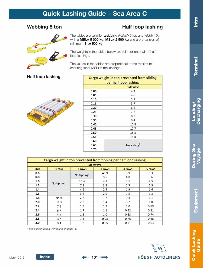
Quic
k La
shin
gG
uid
eIn
tro
Term
inal
Loadin
g/
Dis
charg
ing
Duri
ng S
ea
Voya
ge
Equip
ment
Index 101March 2016
Quick Lashing Guide – Sea Area C
Cargo weight in ton prevented from sliding per half loop lashing
μ Sideways 0.00 4.2 0.05 4.6 0.10 5.1 0.15 5.7 0.20 6.4 0.25 7.2 0.30 8.2 0.35 9.4 0.40 10.8 0.45 12.7 0.50 15.3 0.55 18.8 0.60
No sliding3 0.65 0.70
Cargo weight in ton prevented from �pping per half loop lashing Sideways
H/B 1 row 2 rows 3 rows 4 rows 5 rows 0.6
No �pping3
No �pping3 46.9 9.9 6.3
0.8 8.5 4.8 3.6 1.0 15.6 4.7 3.1 2.5 1.2 7.1 3.2 2.3 1.9 1.4 4.6 2.5 1.9 1.6 1.6 3.4 2.0 1.5 1.3 1.8 31.3 2.7 1.7 1.3 1.1 2.0 12.5 2.2 1.4 1.2 1.0 2.2 7.8 1.9 1.3 1.0 0.89 2.4 5.7 1.7 1.1 0.92 0.81 2.6 4.5 1.5 1.0 0.83 0.74 2.8 3.7 1.3 0.93 0.76 0.68 3.0 3.1 1.2 0.85 0.71 0.63
Webbing 5 ton Half loop lashing
The tables are valid for webbing Rollash 5 ton and Webb 10 m with a MBL= 5 000 kg, MSL= 2 500 kg and a pre-tension of minimum STF= 500 kg.
The weights in the tables below are valid for one pair of half loop lashings.
The values in the tables are proportional to the maximum securing load (MSL) in the lashings.
Half loop lashing
3) See section about wandering on page 99

Quic
k La
shin
gG
uid
eIn
tro
Term
inal
Loadin
g/
Dis
charg
ing
Duri
ng S
ea
Voya
ge
Equip
ment
Index 102March 2016
Quick Lashing Guide – Sea Area C
Webbing 5 ton Straight/cross lashing
The tables are valid for webbing Rollash 5 ton and Webb 10 m with a MBL= 5 000 kg, MSL= 2 500 kg and a pre-tension of minimum STF= 500 kg.
The values in the tables are proportional to the lashings’ maxi-mum securing load (MSL).
All weights are valid for one straight/cross lashing.
Straight/cross lashing
3) See section about wandering on page 994) For correction factor F, see page 92
Cargo weight in ton prevented from sliding per straight/cross lashing
μμ SIDEWAYS FORWARD/BACKWARD 0-30˚ 30-60˚ 0-30˚ 30-60˚
0.00 1.8 1.0 4.3 2.5 0.05 2.0 1.3 4.7 2.9 0.10 2.2 1.5 5.0 3.4 0.15 2.5 1.8 5.4 3.8 0.20 2.8 2.1 5.7 4.3 0.25 3.0 2.5 5.9 4.9 0.30 3.3 3.0 6.1 5.4 0.35 3.7 3.5 6.3 6.0 0.40 4.2 4.3 6.6 6.7 0.45 4.8 5.2 6.8 7.4 0.50 5.6 6.4 7.1 8.2 0.55 6.7 8.1 7.5 9.1 0.60
No sliding3 7.8 10.0
0.65 8.2 11.0 0.70 8.6 12.0
F4 1.8 1.4 1.8 1.4
Cargo weight in ton prevented from �pping per straight/cross lashing
H/B Sideways, per side H/L Forward/backward
≤≤ 1.6 No �pping3
≤≤ 0.8 No �pping3 1.0 25.0 1.2 13.7 1.4 10.0 1.6 8.1
1.8 21.9 1.8 7.0 2.0 9.4 2.0 6.2 2.2 6.3 2.2 5.7 2.4 4.8 2.4 5.3 2.6 4.0 2.6 5.0 2.8 3.5 2.8 4.7 3.0 3.1 3.0 4.5 F4 2.0 F4 2.0
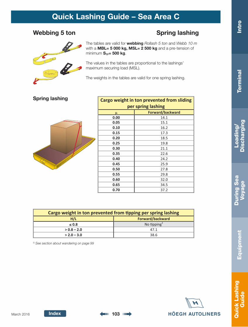
Quic
k La
shin
gG
uid
eIn
tro
Term
inal
Loadin
g/
Dis
charg
ing
Duri
ng S
ea
Voya
ge
Equip
ment
Index 103March 2016
Quick Lashing Guide – Sea Area C
Webbing 5 ton Spring lashing
The tables are valid for webbing Rollash 5 ton and Webb 10 m with a MBL= 5 000 kg, MSL= 2 500 kg and a pre-tension of minimum STF= 500 kg.
The values in the tables are proportional to the lashings’maximum securing load (MSL).
The weights in the tables are valid for one spring lashing.
Spring lashing
3) See section about wandering on page 99
Cargo weight in ton prevented from sliding per spring lashing
μ Forward/backward 0.00 14.1 0.05 15.1 0.10 16.2 0.15 17.3 0.20 18.5 0.25 19.8 0.30 21.1 0.35 22.6 0.40 24.2 0.45 25.9 0.50 27.8 0.55 29.8 0.60 32.0 0.65 34.5 0.70 37.2
Cargo weight in ton prevented from �pping per spring lashing H/L Forward/backward ≤≤ 0.8 No �pping3
> 0.8 – 2.0 47.1 > 2.0 – 3.0 38.6

Quic
k La
shin
gG
uid
eIn
tro
Term
inal
Loadin
g/
Dis
charg
ing
Duri
ng S
ea
Voya
ge
Equip
ment
Index 104March 2016
Quick Lashing Guide – Sea Area C
Cargo weight in ton prevented from sliding per top-over lashing
μ Sideways Forward/backward 0.00 0.00 0.00 0.05 0.08 0.18 0.10 0.17 0.38 0.15 0.29 0.59 0.20 0.43 0.83 0.25 0.62 1.1 0.30 0.87 1.4 0.35 1.2 1.7 0.40 1.7 2.0 0.45 2.6 2.4 0.50 4.4 2.9 0.55 9.6 3.4 0.60
No sliding3 4.0
0.65 4.7 0.70 5.5
Cargo weight in ton prevented from �pping per top-over lashing Sideways Forward/backward
H/B 1 row 2 rows 3 rows 4 rows 5 rows H/L per sec�on 0.6
No �pping3
No �pping3 16.5 3.5 2.2
≤ 0.8 No �pping3 0.8 3.0 1.7 1.3 1.0 5.5 1.7 1.1 0.88 1.0 17.4 1.2 2.5 1.1 0.82 0.68 1.2 8.7 1.4 1.6 0.87 0.65 0.55 1.4 5.8 1.6 1.2 0.70 0.54 0.47 1.6 4.3 1.8 10.9 0.94 0.59 0.47 0.40 1.8 3.5 2.0 4.4 0.78 0.51 0.41 0.35 2.0 2.9 2.2 2.7 0.67 0.45 0.36 0.32 2.2 2.5 2.4 2.0 0.58 0.40 0.32 0.29 2.4 2.2 2.6 1.6 0.52 0.36 0.29 0.26 2.6 1.9 2.8 1.3 0.46 0.33 0.27 0.24 2.8 1.7 3.0 1.1 0.42 0.30 0.25 0.22 3.0 1.6
Webbing 10 ton Top-over lashing
The tables are valid for webbing Rollash 10 ton and Webb with a MBL= 10 000 kg, MSL= 5 000 kg and a pre-tension of minimum STF= 500 kg.
The values in the tables are proportional to the lashings’ pre-tension.
The weights in the tables are valid for one top-over lashing.
If more than one top-over lashing is applied, these are to be evenly distributed over the length of the cargo.
Top-over lashing
3) See section about wandering on page 99
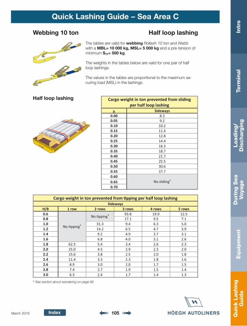
Quic
k La
shin
gG
uid
eIn
tro
Term
inal
Loadin
g/
Dis
charg
ing
Duri
ng S
ea
Voya
ge
Equip
ment
Index 105March 2016
Quick Lashing Guide – Sea Area C
Cargo weight in ton prevented from sliding per half loop lashing
μ Sideways 0.00 8.3 0.05 9.2 0.10 10.2 0.15 11.4 0.20 12.8 0.25 14.4 0.30 16.3 0.35 18.7 0.40 21.7 0.45 25.5 0.50 30.6 0.55 37.7 0.60
No sliding3 0.65 0.70
Cargo weight in ton prevented from �pping per half loop lashing Sideways
H/B 1 row 2 rows 3 rows 4 rows 5 rows 0.6
No �pping3
No �pping3 93.8 19.9 12.5
0.8 17.1 9.5 7.1 1.0 31.3 9.4 6.3 5.0 1.2 14.2 6.5 4.7 3.9 1.4 9.2 4.9 3.7 3.1 1.6 6.8 4.0 3.1 2.6 1.8 62.5 5.4 3.4 2.6 2.3 2.0 25.0 4.5 2.9 2.3 2.0 2.2 15.6 3.8 2.5 2.0 1.8 2.4 11.4 3.3 2.3 1.8 1.6 2.6 8.9 3.0 2.0 1.7 1.5 2.8 7.4 2.7 1.9 1.5 1.4 3.0 6.3 2.4 1.7 1.4 1.3
Webbing 10 ton Half loop lashing
The tables are valid for webbing Rollash 10 ton and Webb with a MBL= 10 000 kg, MSL= 5 000 kg and a pre-tension of minimum STF= 500 kg.
The weights in the tables below are valid for one pair of half loop lashings.
The values in the tables are proportional to the maximum se-curing load (MSL) in the lashings.
Half loop lashing
3) See section about wandering on page 99
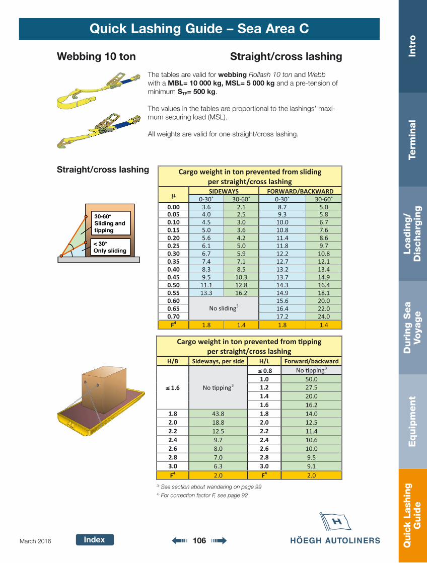
Quic
k La
shin
gG
uid
eIn
tro
Term
inal
Loadin
g/
Dis
charg
ing
Duri
ng S
ea
Voya
ge
Equip
ment
Index 106March 2016
Quick Lashing Guide – Sea Area C
Webbing 10 ton Straight/cross lashing
The tables are valid for webbing Rollash 10 ton and Webb with a MBL= 10 000 kg, MSL= 5 000 kg and a pre-tension of minimum STF= 500 kg.
The values in the tables are proportional to the lashings’ maxi-mum securing load (MSL).
All weights are valid for one straight/cross lashing.
Straight/cross lashing
3) See section about wandering on page 994) For correction factor F, see page 92
Cargo weight in ton prevented from sliding per straight/cross lashing
μ SIDEWAYS FORWARD/BACKWARD 0-30˚ 30-60˚ 0-30˚ 30-60˚
0.00 3.6 2.1 8.7 5.0 0.05 4.0 2.5 9.3 5.8 0.10 4.5 3.0 10.0 6.7 0.15 5.0 3.6 10.8 7.6 0.20 5.6 4.2 11.4 8.6 0.25 6.1 5.0 11.8 9.7 0.30 6.7 5.9 12.2 10.8 0.35 7.4 7.1 12.7 12.1 0.40 8.3 8.5 13.2 13.4 0.45 9.5 10.3 13.7 14.9 0.50 11.1 12.8 14.3 16.4 0.55 13.3 16.2 14.9 18.1 0.60
No sliding3 15.6 20.0
0.65 16.4 22.0 0.70 17.2 24.0
F4 1.8 1.4 1.8 1.4
Cargo weight in ton prevented from �pping per straight/cross lashing
H/B Sideways, per side H/L Forward/backward
≤ 1.6 No �pping3
≤ 0.8 No �pping3 1.0 50.0 1.2 27.5 1.4 20.0 1.6 16.2
1.8 43.8 1.8 14.0 2.0 18.8 2.0 12.5 2.2 12.5 2.2 11.4 2.4 9.7 2.4 10.6 2.6 8.0 2.6 10.0 2.8 7.0 2.8 9.5 3.0 6.3 3.0 9.1 F4 2.0 F4 2.0
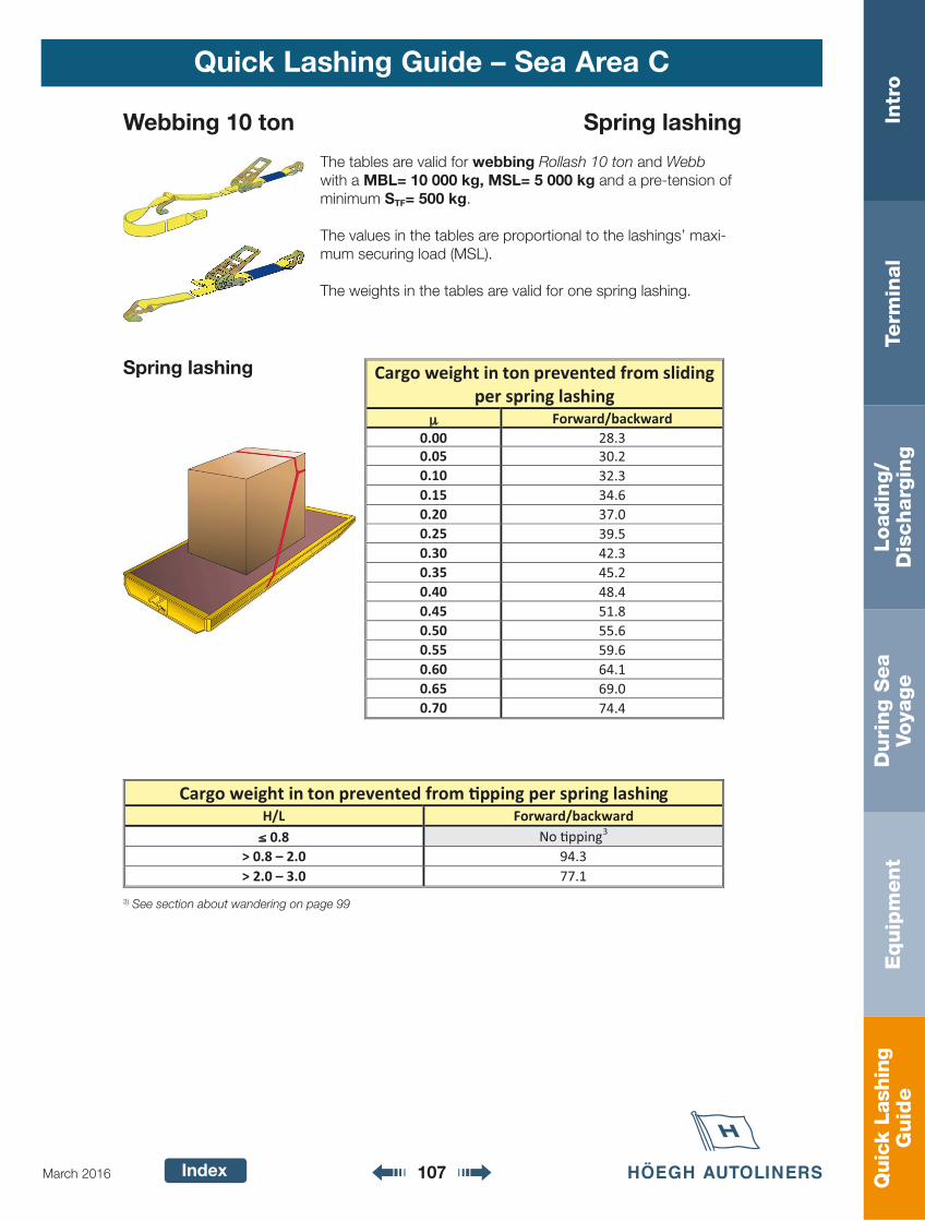
Quic
k La
shin
gG
uid
eIn
tro
Term
inal
Loadin
g/
Dis
charg
ing
Duri
ng S
ea
Voya
ge
Equip
ment
Index 107March 2016
Quick Lashing Guide – Sea Area C
Webbing 10 ton Spring lashing
The tables are valid for webbing Rollash 10 ton and Webb with a MBL= 10 000 kg, MSL= 5 000 kg and a pre-tension of minimum STF= 500 kg.
The values in the tables are proportional to the lashings’ maxi-mum securing load (MSL).
The weights in the tables are valid for one spring lashing.
Spring lashing
3) See section about wandering on page 99
Cargo weight in ton prevented from sliding per spring lashing
μ Forward/backward 0.00 28.3 0.05 30.2 0.10 32.3 0.15 34.6 0.20 37.0 0.25 39.5 0.30 42.3 0.35 45.2 0.40 48.4 0.45 51.8 0.50 55.6 0.55 59.6 0.60 64.1 0.65 69.0 0.70 74.4
Cargo weight in ton prevented from �pping per spring lashing H/L Forward/backward ≤ 0.8 No �pping3
> 0.8 – 2.0 94.3 > 2.0 – 3.0 77.1

Quic
k La
shin
gG
uid
eIn
tro
Term
inal
Loadin
g/
Dis
charg
ing
Duri
ng S
ea
Voya
ge
Equip
ment
Index 108March 2016
Quick Lashing Guide – Sea Area C
Cargo weight in ton prevented from sliding per top-over lashing
μ Sideways Forward/backward 0.00 0.00 0.00 0.05 0.16 0.36 0.10 0.35 0.76 0.15 0.58 1.2 0.20 0.87 1.7 0.25 1.2 2.2 0.30 1.7 2.7 0.35 2.4 3.4 0.40 3.5 4.1 0.45 5.2 4.9 0.50 8.7 5.8 0.55 19.1 6.8 0.60
No sliding3 8.0
0.65 9.4 0.70 11.1
Cargo weight in ton prevented from �pping per top-over lashing Sideways Forward/backward
H/B 1 row 2 rows 3 rows 4 rows 5 rows H/L per sec�on 0.6
No �pping3
No �pping3 33.0 7.0 4.4
≤≤ 0.8 No �pping3 0.8 6.0 3.4 2.5 1.0 10.9 3.3 2.2 1.8 1.0 34.8 1.2 5.0 2.3 1.6 1.4 1.2 17.4 1.4 3.2 1.7 1.3 1.1 1.4 11.6 1.6 2.4 1.4 1.1 0.93 1.6 8.7 1.8 21.7 1.9 1.2 0.93 0.80 1.8 7.0 2.0 8.7 1.6 1.0 0.81 0.71 2.0 5.8 2.2 5.4 1.3 0.89 0.72 0.63 2.2 5.0 2.4 4.0 1.2 0.79 0.65 0.57 2.4 4.3 2.6 3.1 1.0 0.72 0.59 0.52 2.6 3.9 2.8 2.6 0.93 0.65 0.54 0.48 2.8 3.5 3.0 2.2 0.84 0.60 0.50 0.44 3.0 3.2
Chain Ø 9 mm Top-over lashing
The tables are valid for chain Ø 9 mm with a MBL= 10 000 kg, MSL= 5 000 kg and a pre-tension of minimum STF= 1 000 kg.
The values in the tables are proportional to the lashings’ pre-tension.
The weights in the tables are valid for one top-over lashing.
If more than one top-over lashing is applied, these are to be evenly distributed over the length of the cargo.
Top-over lashing
3) See section about wandering on page 99
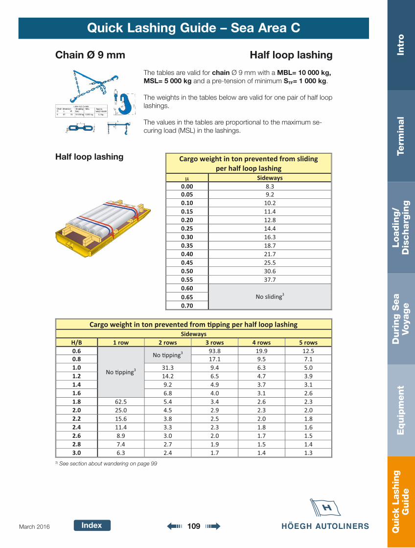
Quic
k La
shin
gG
uid
eIn
tro
Term
inal
Loadin
g/
Dis
charg
ing
Duri
ng S
ea
Voya
ge
Equip
ment
Index 109March 2016
Quick Lashing Guide – Sea Area C
Chain Ø 9 mm Half loop lashing
The tables are valid for chain Ø 9 mm with a MBL= 10 000 kg, MSL= 5 000 kg and a pre-tension of minimum STF= 1 000 kg.
The weights in the tables below are valid for one pair of half loop lashings.
The values in the tables are proportional to the maximum se-curing load (MSL) in the lashings.
Half loop lashing
3) See section about wandering on page 99
Cargo weight in ton prevented from sliding per half loop lashing
μ Sideways 0.00 8.3 0.05 9.2 0.10 10.2 0.15 11.4 0.20 12.8 0.25 14.4 0.30 16.3 0.35 18.7 0.40 21.7 0.45 25.5 0.50 30.6 0.55 37.7 0.60
No sliding3 0.65 0.70
Cargo weight in ton prevented from �pping per half loop lashing Sideways
H/B 1 row 2 rows 3 rows 4 rows 5 rows 0.6
No �pping3
No �pping3 93.8 19.9 12.5
0.8 17.1 9.5 7.1 1.0 31.3 9.4 6.3 5.0 1.2 14.2 6.5 4.7 3.9 1.4 9.2 4.9 3.7 3.1 1.6 6.8 4.0 3.1 2.6 1.8 62.5 5.4 3.4 2.6 2.3 2.0 25.0 4.5 2.9 2.3 2.0 2.2 15.6 3.8 2.5 2.0 1.8 2.4 11.4 3.3 2.3 1.8 1.6 2.6 8.9 3.0 2.0 1.7 1.5 2.8 7.4 2.7 1.9 1.5 1.4 3.0 6.3 2.4 1.7 1.4 1.3
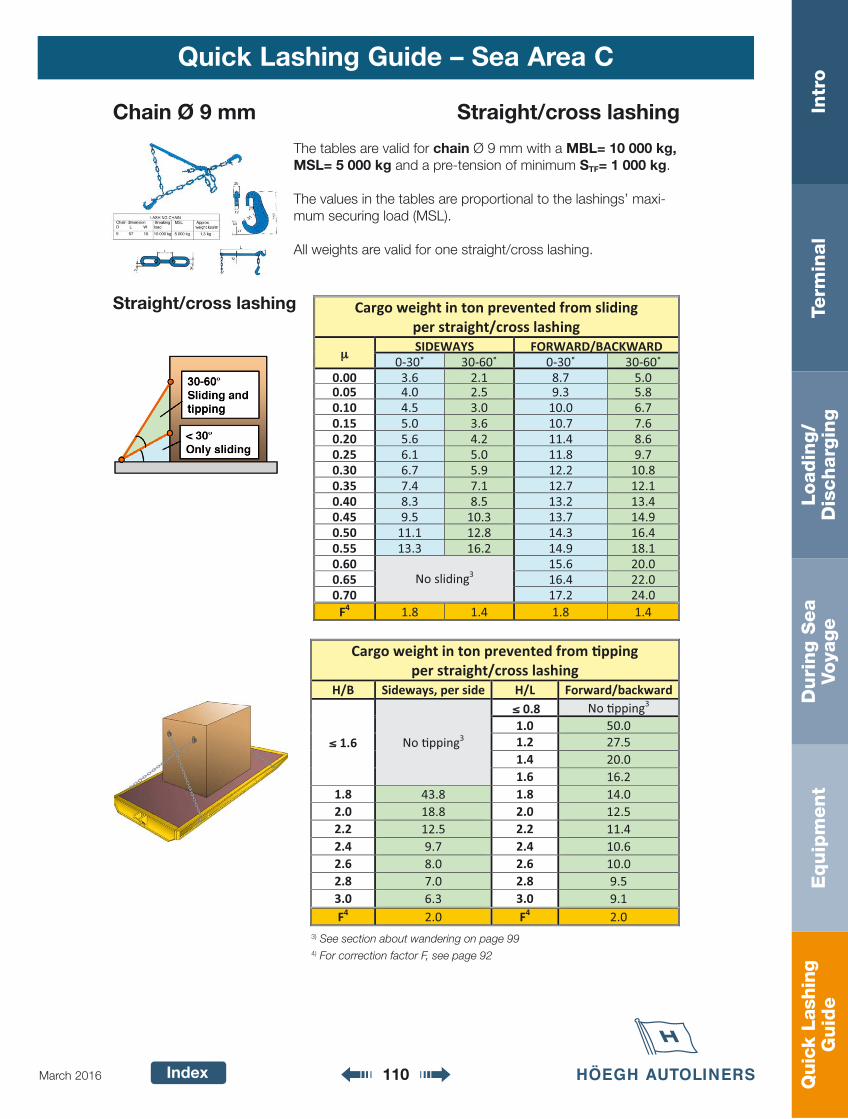
Quic
k La
shin
gG
uid
eIn
tro
Term
inal
Loadin
g/
Dis
charg
ing
Duri
ng S
ea
Voya
ge
Equip
ment
Index 110March 2016
Quick Lashing Guide – Sea Area C
Cargo weight in ton prevented from sliding per straight/cross lashing
μμ SIDEWAYS FORWARD/BACKWARD 0-30˚ 30-60˚ 0-30˚ 30-60˚
0.00 3.6 2.1 8.7 5.0 0.05 4.0 2.5 9.3 5.8 0.10 4.5 3.0 10.0 6.7 0.15 5.0 3.6 10.7 7.6 0.20 5.6 4.2 11.4 8.6 0.25 6.1 5.0 11.8 9.7 0.30 6.7 5.9 12.2 10.8 0.35 7.4 7.1 12.7 12.1 0.40 8.3 8.5 13.2 13.4 0.45 9.5 10.3 13.7 14.9 0.50 11.1 12.8 14.3 16.4 0.55 13.3 16.2 14.9 18.1 0.60
No sliding3 15.6 20.0
0.65 16.4 22.0 0.70 17.2 24.0
F4 1.8 1.4 1.8 1.4
Cargo weight in ton prevented from �pping per straight/cross lashing
H/B Sideways, per side H/L Forward/backward
≤≤ 1.6 No �pping3
≤≤ 0.8 No �pping3 1.0 50.0 1.2 27.5 1.4 20.0 1.6 16.2
1.8 43.8 1.8 14.0 2.0 18.8 2.0 12.5 2.2 12.5 2.2 11.4 2.4 9.7 2.4 10.6 2.6 8.0 2.6 10.0 2.8 7.0 2.8 9.5 3.0 6.3 3.0 9.1 F4 2.0 F4 2.0
Chain Ø 9 mm Straight/cross lashing
The tables are valid for chain Ø 9 mm with a MBL= 10 000 kg, MSL= 5 000 kg and a pre-tension of minimum STF= 1 000 kg.
The values in the tables are proportional to the lashings’ maxi-mum securing load (MSL).
All weights are valid for one straight/cross lashing.
Straight/cross lashing
3) See section about wandering on page 994) For correction factor F, see page 92
Quic
k La
shin
gG
uid
eIn
tro
Term
inal
Loadin
g/
Dis
charg
ing
Duri
ng S
ea
Voya
ge
Equip
ment
Index 111March 2016
Quick Lashing Guide – Sea Area C
Cargo weight in ton prevented from sliding per spring lashing
μ Forward/backward 0.00 28.3 0.05 30.2 0.10 32.3 0.15 34.6 0.20 37.0 0.25 39.5 0.30 42.3 0.35 45.2 0.40 48.4 0.45 51.8 0.50 55.6 0.55 59.6 0.60 64.1 0.65 69.0 0.70 74.4
Cargo weight in ton prevented from �pping per spring lashing H/L Forward/backward ≤≤ 0.8 No �pping3
> 0.8 – 2.0 94.3 > 2.0 – 3.0 77.1
Chain Ø 9 mm Spring lashing
The tables are valid for chain Ø 9 mm with a MBL= 10 000 kg, MSL= 5 000 kg and a pre-tension of minimum STF= 1 000 kg.
The values in the tables are proportional to the lashings’ maxi-mum securing load (MSL).
The weights in the tables are valid for one spring lashing.
Spring lashing
3) See section about wandering on page 99
Quic
k La
shin
gG
uid
eIn
tro
Term
inal
Loadin
g/
Dis
charg
ing
Duri
ng S
ea
Voya
ge
Equip
ment
Index
Quick Lashing Guide – Sea Area C
This quick lashing guide is prepared in accordance with
the principles in the CTU Code in cooperation with:
PO BOX 4 Skøyen
N-0212 Oslo, Norway
Phone: +47 (0)21 03 90 00
www.hoegh.com
P.O. Box 74
SE-263 21 Höganäs, Sweden
Phone: +46 (0)42 33 31 00
www.mariterm.se


