6
Heimdall traffic detector family Traffic Solutions

Heimdalltraffic detector family
Traffic Solutions

Heimdall traffic detector family
Heimdall above-ground detectors offer a complete range of detection systems for use in many modern traffic andpedestrian control applications.
Using the latest 24GHz radar technology, these detectorsoffer high performance, simple installation and lowongoing maintenance, while their small size ensures thatunnecessary street clutter is minimised.
Patented technology
At the heart of each detector is a technologically advancedplanar radar antenna system and a sophisticated digital signalprocessing engine. Developed by Siemens, these incorporatepatented features that enable Heimdall to offer a wide rangeof detection solutions, including:
• Dual lane vehicle approach
• Single lane vehicle approach
• Stop line
• Selectable speed activation
• SCOOT
• MOVA
To deliver these solutions effectively, the Heimdall familyincorporates many unique benefits, including:
Simple installationHeimdall detectors are supplied pre-configured with standardsettings, which are suitable for the majority of installations.When on-site customisation is required, this can be achievedusing simple configuration switch settings, which eliminatesthe need to use expensive and vulnerable PC or PDA-basedconfiguration tools. Only when access to advanced settings ordetailed fault log information is required will it be necessary touse a PC or a PDA. If required, Heimdall can be supplied with
Bluetooth functionality, allowing these functions to beaccessed from ground level.
PC and PDA access can utilise a simple terminal program, so itis not necessary to purchase expensive propriety software toaccess Heimdall detectors using these tools.
High performanceUnlike some vision-based systems, Heimdall’s radar technologyeliminates false detection due to light level changes and theeffect of shadows and will continue to work equally well inboth bright and totally dark locations. Similarly, the effects of fog and rain, which can severely affect the performance of vision-based systems, go largely unnoticed when Heimdall is deployed, ensuring the best possible performance of theroad network, whatever the conditions.
Reduced maintenanceOngoing maintenance costs are sometimes a concern, particularly with camera-based detection systems, wherefrequent lens cleaning may be necessary to maintainperformance. Heimdall’s radar-based technology means such maintenance is not required, offering considerable cost savings.
Each detector in the Heimdall family offers unique features and performance characteristics, providing a complete range of solutions for all your detection needs.
Dual lane vehicle approach
The CW Doppler-based dual lane vehicle detector is typicallyused to detect and monitor vehicles at signalled junctions, orwherever the detection of moving targets is required in a longdetection zone, for example, to provide demand and extensionrequests to an associated traffic controller.
The zone is broad enough to cover two approach lanessimultaneously, and the detector is able to discriminatebetween approaching and receding traffic.
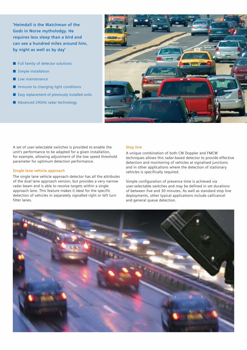
‘Heimdall is the Watchman of the
Gods in Norse mytholodgy. He
requires less sleep than a bird and
can see a hundred miles around him,
by night as well as by day’
� Full family of detector solutions
� Simple installation
� Low maintenance
� Immune to changing light conditions
� Easy replacement of previously installed units
� Advanced 24GHz radar technology
A set of user-selectable switches is provided to enable theunit’s performance to be adapted for a given installation, for example, allowing adjustment of the low speed thresholdparameter for optimum detection performance.
Single lane vehicle approach
The single lane vehicle approach detector has all the attributesof the dual lane approach version, but provides a very narrowradar beam and is able to resolve targets within a singleapproach lane. This feature makes it ideal for the specificdetection of vehicles in separately signalled right or left turnfilter lanes.
Stop line
A unique combination of both CW Doppler and FMCWtechniques allows this radar-based detector to provide effectivedetection and monitoring of vehicles at signalised junctionsand in other applications where the detection of stationaryvehicles is specifically required.
Simple configuration of presence time is achieved via user-selectable switches and may be defined in set durationsof between five and 30 minutes. As well as standard stop linedeployments, other typical applications include call/cancel and general queue detection.

Selectable speed activation
Speed threshold setup is achieved via simple configurationswitches, with other parameters such as hold and delay timesbeing configurable using a PC or PDA.
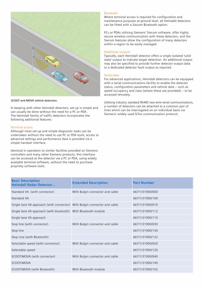
SCOOT and MOVA
Designed to operate in a ‘side fire’ configuration, this singlelane FMCW radar detector, with advanced signal processing,offers excellent count and occupancy performance as well as
good ‘gap’ detection capabilities and is ideal for SCOOT andMOVA applications.
For optimum performance, the detector is mounted at a height of 4m, but they may be mounted at a range of heights from4m to 8m. Where dual lane detection is needed, a secondHeimdall unit may be mounted above the first to cover thesecond lane.
Application examples.
Single lane vehicle approach
Dual lane vehicle approach
Single lane vehicle approach usingstandard dual lane detector
set for approach detection only
Stop linedetection
In keeping with other Heimdall detectors, set-up is simple andcan usually be done without the need for a PC or PDA.The Heimdall family of traffic detectors incorporates thefollowing additional features:
Terminal accessAlthough most set-up and simple diagnostic tasks can beundertaken without the need to use PC or PDA tools, access toadvanced settings and performance data is provided via asimple handset interface.
Identical in operation to similar facilities provided on Siemenscontrollers and many other Siemens products, this interfacecan be accessed at the detector via a PC or PDA, using widelyavailable terminal software, without the need to purchasepropriety software tools.
SCOOT and MOVA vehicle detection.
Basic DescriptionHeimdall Radar Detector…
Extended Description Part Number
Standard VA (with connector) With Bulgin connector and cable 667/1/31900/000
Standard VA 667/1/31900/100
Single lane VA approach (with connector) With Bulgin connector and cable 667/1/31900/010
Single lane VA approach (with bluetooth) With Bluetooth module 667/1/31900/112
Single lane VA approach 667/1/31900/110
Stop line (with connector) With Bulgin connector and cable 667/1/31900/030
Stop line 667/1/31900/130
Stop Line (with Bluetooth) 667/1/31900/132
Selectable speed (with connector) With Bulgin connector and cable 667/1/31900/020
Selectable speed 667/1/31900/120
SCOOT/MOVA (with connector) With Bulgin connector and cable 667/1/31900/040
SCOOT/MOVA 667/1/31900/140
SCOOT/MOVA (with Bluetooth) With Bluetooth module 667/1/31900/142
BluetoothWhere terminal access is required for configuration andmaintenance purposes at ground level, all Heimdall detectorscan be fitted with a Siecom Bluetooth option.
PCs or PDAs utilising Siemens’ Siecom software, offer highlysecure wireless communication with these detectors, and theSiecom features allow the configuration of many detectorswithin a region to be easily managed.
Additional outputsTypically, each Heimdall detector offers a single isolated ‘solidstate’ output to indicate target detection. An additional outputmay also be specified to provide further detector output dataor a dedicated detector fault output as required.
Serial dataFor advanced applications, Heimdall detectors can be equippedwith a serial communications facility to enable the detectorstatus, configuration parameters and vehicle data – such asspeed occupancy and class (where these are provided) – to beaccessed remotely.
Utilising industry standard RS485 two-wire serial communications,a number of detectors can be attached to a common pair oflines which can be interrogated on an individual basis viaSiemens’ widely used SiTos communication protocol.

For further information, please contact: Siemens Mobility, Traffic Solutions, Sopers Lane, Poole, Dorset BH17 7ER UK
Telephone: +44 (0) 1202 782000E-mail: [email protected]
www.siemens.co.uk/traffic
© Siemens plc 2009. All rights reserved.
This publication is issued to provide outline information only,which (unless agreed by the Company in writing) may not beused, applied or reproduced for any purpose or form part ofany order or contract or be regarded as a representation relating to the products or service concerned. The Companyreserves the right to alter without notice this specification,design, price or conditions of supply of any product or service.
TS-BR20-16
Technical specification
General for all detectors
• Approval:
UK Highways Agency specifications: TR2505EMC: EN50293Radio approval: EN 300 440
• Supply voltage: 24V AC ± 20% (48 to 63 Hz), or 24V DC ± 20%
• Typical supply current:
143mA (AC)113mA (DC)186mA (AC) – with wireless or serial data options147mA (AC) – with wireless or serial data options
• Dimensions:150mm (h) x 135mm (w) x 90mm (d) (to the bottom of mounting bracket)
• Weight: Less than 1.6kg
• Standard connection: Defined Bulgin Buccaneer connector and pin-out or internal screw connector for connection of customer defined termination
Specific detectors
Dual lane vehicle approach
• Operating range: At least 10m to 35m from the Stop Line. Typically up to 70m for saloon car
• Lane width: Typically 7.0m
• Vehicle approach speed: 8km/hr (5mph) to greater than 112km/hr (70 mph). Configurable detection direction: Approaching, receding or both
• Detector location: Can be located on either the ‘nearside’ primary signal pole or the ‘off side’ primary signal pole
• Detector mounting height: Various heights (above the ground) can be accommodated from 3.3m to 4.0m
Single lane vehicle approach
• Operating range: At least 10m to 35m from the Stop LineTypically up to 70m for saloon car
• Lane width: Typically 3.5m
• Vehicle approach speed: 8km/hr (5mph) to greater than 112km/hr (70mph). Configurable detection direction: Approaching, receding or both
• Detector location: Can be located on either the ‘nearside’ primary signal pole or the ‘off side’ primary signal pole
• Detector mounting height: Various heights (above the ground) can be accommodated from 3.3m to 4.0m
Stop line
• Operating range: At least 3m from the Stop Line
• Lane width: Typically 3.5m
• Vehicle approach speed: Not applicable (stationary vehicle detection system)
• Detection presence time: At least 30 minutes. Configurable by dip switch settings and terminal
• Detector location: Can be located on either the ‘nearside’ primary signal pole or the ‘off side’ primary signal pole
• Detector mounting height: Various heights (above the ground) can be accommodated from 3.3m to 4.0m
Selectable speed activation
• Operating range: At least 10m to 35m from the Stop LineTypically up to 70m for saloon car
• Lane width: Typically 7.0m
• Vehicle approach speed: 8km/hr (5mph) to greater than
112km/hr (70mph)
• Speed threshold settings: 8km/hr (5mph) to 112km/hr (70mph) by simple DIP switch settings. Can be configured from 8km/hr to 150km/hr in 1km/hr increments via the terminal facility
• Detector location: Can be located on either the ‘nearside’ primary signal pole or the ‘off side’ primary signal pole
• Detector mounting height: Various heights (above the ground) can be accommodated from 3.3m to 4.0m
SCOOT/MOVA
• Operating range: Single lane adjacent to mounting pole
• Lane width: Replicates the function of a normal SCOOT/MOVA loop
• Vehicle approach speed: 0km/hr (0mph) to greater than 112 km/hr (70mph)
• Detection presence time: At least 30 minutes. Configurable
by terminal
• Data accuracy:Count: better than 98%Occupancy: better than 98%(Data available serially if SiTos serial link fitted)
• Detector location: Can be located on either the ‘nearside’ primary signal pole or the ‘off side’ primary signal pole, towards traffic flow or ‘side fire’ across lane being monitored
• Detector mounting height: Various heights (above the ground) can be accommodated from 3.3m to 8.0m. Actual SCOOT ‘footprint’ will be dependant on the mounting height
• Detector Mounting Height: Various heights (above the ground) can be accommodated from 5.0m to 7.0m - mounting heights of 6.0m minimum recommended for detection in second lane


![Building Blocks for a 24GHz Phased-Array Front-End …Wan14] PIERS B.pdf · Building Blocks for a 24GHz Phased-Array Front-End in CMOS Technology for Smart Streetlights ... bypassing](https://static.documents.pub/doc/80x56/5b80934b7f8b9af0088db508/building-blocks-for-a-24ghz-phased-array-front-end-wan14-piers-bpdf-building.jpg)


