NASA Contractor Report 196697 USAATCOM Technical Report 94-A-021 ro Helmet-Mounted Display Symbology and Stabilization Concepts Richard L. Newman CONTRACT NAS2-13811 June 1995 j^M •'WfnSBuTKWHlSfSS ~Z&£&£1 National Aeronautics and Space Administration °°t><*U*w t *»omUTMD I US Army Aviation and Troop Command Aeroflightdynamics Directorate Moffett Field, CA 94035-1000
Transcript
NASA Contractor Report 196697 USAATCOM Technical Report 94-A-021
ro
Helmet-Mounted Display Symbology and Stabilization Concepts
Richard L. Newman
CONTRACT NAS2-13811 June 1995
j^M •'WfnSBuTKWHlSfSS
~Z&£&£1 National Aeronautics and Space Administration
°°t><*U*wt *»omUTMD I
US Army Aviation and Troop Command
Aeroflightdynamics Directorate Moffett Field, CA 94035-1000
NASA Contractor Report 196697 USAATCOM Technical Report 94-A-021
Helmet-Mounted Display Symbology and Stabilization Concepts
Richard L. Newman
Crew Systems P. O. Box 963 San Marcos, Texas 78667
Prepared for Ames Research Center CONTRACT NAS2-13811 June 1995
National Aeronautics and Space Administration
Ames Research Center Moffett Field, CA 94035-1000
US Army Aviation and Troop Command
Aeroflightdynamics Directorate Moffett Field, CA 94035-1000
CONTENTS
Page
LIST OF FIGURES v
LIST OF TABLES v
ABBREVIATIONS vii
POINTS OF CONTACT xi
SUMMARY xiii
A BACKGROUND 1 (1) Statement of the Problem 1 (2) The Real Problem 2
B PROBLEMS WITH VIRTUAL DISPLAYS 5 (1) Lessons Learned from HUD Developments 5 (2) Problems Unique to HMDs 7 (3) Summary 9
C DEFINITIONS 11 (1) Frequently Used Terms 11 (2) Stabilization Terms 12
D HMD SYSTEMS 13 (1) Operational and Developmental HMDs 13 (2) Research HMDs 13 (3) HMD Simulators 14 (4) Helicopter HUD Systems 15
E HMD SYMBOLOGY SUMMARY 17 (1) Operational HMDs 17 (2) Rotorcraft HMDs Under Development 18 (3) Helicopter HUDs 21 (3) Proposed Fixed-Wing HMDs 21
F SYMBOLOGY STABILIZATION 33 (1) General Comments 33 (2) Coordinate Systems 33 (3) Symbol Orientation 34 (4) Symbol Location 34
in
G HMD LESSONS LEARNED TO DATE 39 (1) Training 39 (2) Operations 39 (3) Research 40 (4) Observations 41
H RESTATEMENT OF THE PROBLEM 43
I THE HELMET-MOUNTED DISPLAY DESIGN GUIDE 45 (1) Previous Design Documents 45 (2) Strawman HMD Design Guide 46 (3) Database Development 48
J POTENTIAL BENEFITS 51 (1) Reduced Design Cost 51 (2) Civil Operators 51 (3) Military Operators 51 (4) External Load Operations 52 (5) Other Uses of HMDs 52
K RESULTS AND RECOMMENDATIONS 53 (1) Results 53 (2) Recommendations 53
SPIRIT Simulation Program for Improved Rotorcraft Integration Technology
viii
TLAR
UH-1N
UH-60
UK
US
USAF
USASC
That looks about right.
Military Helicopter, Huey
Military Helicopter, Blackhawk
United Kingdom
United States
US Air Force
US Army Safety Center
IX
Points of Contact
During the course of the Phase I study, the following organizations and individuals were contacted. Some of the contacts occurred during professional meetings and symposia.
1 Advanced Aviation Concepts Mr. Richard Adams
2 Air Methods Capt. Leroy Jackson Capt. Andy McJohnston
3 Boeing Helicopter Mr. Ryan Wilkins
4 CAE Electronics Dr. Ronald Kruk
5 Federal Aviation Administration Mr. Peter Hwoschinsky Mr. Paul Erway Mr. Stephen Hickok Dr. Garry Headley
6 Flight Visions Mr. Mark Phillips Mr. Herb White
7 GEC Avionics Mr. Steve Brown Mr. Robin Sleight
8 Hoh Aeronautics Mr. Roger Hoh
9 Honeywell Mr. Robert North Mr. JeffRadke
10 Kaiser Electronics Mr. Joseph Garcia
11 Petroleum Helicopters Mr. Vern Albert
XI
12 Research Triangle Park Mr. Malcolm Burgess
13 Sextant Avionique Mr. Luc Baron Dr. Alain Leger Mr. Roger Parus
14 Sikorsky Mr. Nick Lappos Mr. Robert Warren
15 STC Corporation Dr. Donald Richardson
16 US Air Force (Wright-Patterson AFB) Mr. Eric Geiselman (University of Dayton) Mr. Dean Kocian S/L Robert Munns Dr. Robert Osgood
17 US Army (Fort Rucker) CW3 John Armbrust CW2 Neil Caldwell CW2 Rick Korycinski CW3 Steven Paris Cpt Douglas Sperandio
18 US Army (Fort Belvoir) Maj Brian Gillespie
19 US Navv/Marine Corps (Patuxent NAS) L/C Andy Lahaszow
Xll
Summary
The helmet-mounted display (HMD) presents flight, sensor, and weapon information in the pilot's line of sight. The HMD was developed to allow the pilot to retain aircraft and weapon information and to view sensor images while looking off boresight.
The only operational helicopter HMD system today is installed in the Apache. This system incorporates a movable infrared sensor which is slaved to the pilot's line of sight. The sensor image is shown on the HMD reticle with symbology embedded in the image. The system was developed to allow contact flight at night. While Apache system meets this design objective, the combination of sensor image and symbology can be confusing and present misleading flight information.
The present study reviewed the current state-of-the-art in HMDs and identified a number of issues applying to HMDs. Several are identical to Head-Up Display (HUD) issues: symbol standardization, excessive clutter, and the need for integration with other cockpit displays and controls. Other issues are unique to the head-mounted display: symbol stabilization, inadequate definitions, undefined symbol drive laws, helmet considerations, and field-of-view (FOV) vs. resolution tradeoff requirements.
In particular, symbol stabilization is a key issue for HMDs. In addition to requiring further experimental studies, it was found to impact the definition and control law issues. Part of the problem is there is no agreed upon set of definitions or descriptions for how HMD symbols are driven to compensate for pilot head motion. A candidate set of definitions is proposed to address this.
Symbol stabilization is critical. In the case of the Apache helicopter, the lack of compensation for pilot head motion creates excessive workload during hovering and nap-of-the-earth (NOE) flight. This high workload translates into excessive training requirements. At the same time, misleading symbology makes interpretation of the height of obstructions impossible.
The underlying cause is inadequate of design criteria for HMDs. The existing military standard does not reflect the current state of technology. In addition, there are generally inadequate test and evaluation guidelines. The situation parallels the state-of-the-art for HUDs several years ago. The major recommendation of this study is the development of an HMD design guide similar to the HUD design guide. A further recommendation calls for the creation of a HMD database in electronic format.
There are several specific areas where additional simulation and flight experiments are needed. These include development of hover and NOE symbology which compensates for pilot head movement and the tradeoff between FOV, sensor resolution and symbology.
Xlll
HELMET-MOUNTED DISPLAY
FLIGHT 8YMB0L06Y AND STABILIZATION CONCEPTS
A BACKGROUND
Virtual image displays present collimated flight symbology and sensor images (infrared, radar, etc.) in the pilot's view of the world. This allows simultaneous viewing of flight information, sensor information, and the real world. These displays come in two varieties: head-up displays (HUDs) and helmet-mounted dis- plays (HMDs) .
HUDs are fixed displays usually mounted at the top of the instru- ment panel. HUDs are becoming the primary fixed-wing flight ref- erence for use during both visual and instrument meteorological conditions. HMDs were developed to accommodate the need for larger field-of-regard (i. e. to look off boresight).
These displays allow presentation of flight-critical information in a variety of new and useful formats and can combine the infor- mation from a large number of sources. This can be both a bless- ing and a curse.
HMDs offer many advantages in terms of weapon delivery and maneu- vering in close proximity to obstacles. They offer advantages in terms of weapon delivery and maneuvering in close proximity to obstacles. At the same time, HMDs present many significant chal- lenges which must be addressed.
As the technology matures, HMDs will be found on more aircraft. At this time, HMDs are found on one operational aircraft (AH-64, Apache), although there are a number of candidate systems being proposed.
(1) Statement of the Problem
The present standard for the HMD describes the symbology for the Apache(1). This standard represented the best information availa- ble at the time of its publication in 1984, but has not kept up with the technology.
In the Apache, the symbology does not compensate for pilot head motion. There have been difficulties reported with this symbol- ogy, both in terms of mission degradation and in terms of exces- sive training costs. In addition, the use of non head-tracked horizon information can result in a flight hazard. For these rea- sons, a new standard should be prepared. The Aeroflightdynamics
1
Directorate (AFDD) is preparing an Aeronautical Design Standard (ADS) to address these topics.
(2) The Real Problem
The real problem is not so much with the existing standard, rath- er it is an indictment of the display design process. The devel- opment of most electronic flight displays does not follow a con- sistent and logical path. Rather the display formats are devel- oped using a "That looks about right" (TLAR) approach.
The display complexity can be looked at as a global to specific hierarchy: at the top, we can consider the general informational requirements, followed by overall systems issues. As we move down the hierarchy, issues be come more specific, first arrangement and dynamics of the display, then the icons, and finally the de- tails of the icons. Most symbology development heretofore has concentrated on the bottom end — defining the icons.
The most important aspect of display design, in our opinion, determining the information requirements has relied on the use of expert pilot opinion. Traditionally, display designers have sought pilot opinion for guidance during the development of new flight displays. While user input is helpful, pilots tend to have diverse (and strongly held) opinions. In addition, pilots with limited background in display evaluation often limit the design of novel systems to those concepts with which they are familiar (i. e., TLAR).
This would be an acceptable, if inefficient, design methodology if there were valid test criteria and a we11-developed test pro- tocol. Unfortunately, neither has been in place. Recently a de- sign handbook has been developed for head-up displays(2). A simi- lar procedure should be developed for HMDs as well.
The display design must consider why the pilot needs the data and what the pilot is expected to do with the data. According to Singleton (3), a number of questions should be considered during the development of a display:
o Does the pilot's need justify the display?
o What data does the pilot need that has not been provided?
o Can the average pilot obtain what is required easily?
o Does the display conform ... • to the real world? • to other cockpit displays? • with previous pilot habits and skills? • with required decisions and actions?(3_)
The development of any display must start with the basic principle of analyzing the mission requirements.The information required by the pilot and crew must be cataloged. Only then can the display symbology be designed. Head-down instruments did not change greatly for many years. As a result, designers forgot this basic principle and concentrated on matching the format of the "basic T."
The final set of questions concerning conformity should not be taken as an absolute requirement for duplicating previous displays or the real world. Rather, it means that the display should not be in conflict with the pilot's experience and training nor with the external cues. It would be foolish to insist that HUDs and HMDs conform exactly to early round-dial instruments or electronic head-down displays.
In 1969, Ketchel and Jenney studied the requirements for electronic displays(4). While their study is technologically dated, the underlying principles of determining the information requirements are still valid today. Their report covered information requirements, symbology design, and display characteristics.
Newman prepared a design handbook for head-up displays which de- scribes a design methodology, presents specific design criteria, and outlines evaluation criteria(2) . This handbook also lists the "lessons learned" from a history of HUD symbology.
Following completion of the display design, its evaluation must be based on objective, performance based criteria and measures of the display's effect on mission performance. It is up to the evaluation team to determine what appropriate flight tasks and performance measures are. These should reflect the intended mis- sion of the aircraft and must include all mission segments.
B PROBLEMS WITH VIRTUAL DISPLAYS
(1) Lessons Learned from HUD Developments
(a) Symbol Standardization: With any electronic aircraft dis- play, head-up, head-down, or helmet-mounted, there are two divergent forces. On the one hand, there is a great clamor for standardization of symbology. At the same time, there is an extraordinary desire to make every aircraft application different. Any student of head-up display (HUD) history will testify to this.
"It is a most interesting fact that one of the first things a pilot exhibits on being exposed to HUD flying is an insatiable drive to redesign it in his/her own image. It borders on a reli- gious experience."(5)
HUDs are see-through, virtual image displays. As such, they are fundamentally different from panel mounted displays. In spite of the differences, HUD symbology often mimics head- down displays. This has resulted in confusion over control techniques, in excessively cluttered displays, and in dis- plays which do not make the best use of the HUD.
Similarly, some proposed HMD symbology formats appear to be copied inappropriately from HUD symbologies.
(b) Lack of Criteria: What has been lacking is any organized set of development, test, and evaluation criteria for displays. As a result, HUD development usually progress through a se- ries of personal preference choices by either the manufac- turer's project pilot or the customer's pilot.
As decisions are made, the rationale for the choices aren't documented. This forces new systems to go through the same process time and again.
(c) Clutter: One of the primary goals for a see-through display is to present the pilot an uncluttered display. Since the pilot will necessarily being looking through a HUD to view the real world, there is an paramount requirement to mini- mize display clutter. Both Newman(2) and Hughes(6) emphasize this. Hughes expressed this principle that not one pixel should be lit unless it "buys" its way onto the screen by providing a demonstrable improvement in performance(6).*
This issue may be more pronounced if a raster sensor image is displayed in conjunction with stroke symbols. No criteria have been generated dealing with raster/symbology combina- tions.
This has been referred to as Hawkeye's Principle.
5
(d) Symbol Control Laws: HUD control laws and algorithms which drive the various symbols have not been well described. The absence of specifications and of documentation has created problems with HUDs where the symbols were excessively noisy (lateral motion of the F-16A FPM) or led to pilot uncertain- ty about the origin of the data (aircraft reference symbol in the MD-80).
Historically, there have been no requirements to deliver the display code as part of the data package. This makes it quite difficult to determine exactly what is displayed and how the symbols are driven. Manufacturers treat the source code as proprietary data. The only algorithms publicly available, to our knowledge, are for the A-7D/E HUD. (7) The USAF has attempted to "reverse engineer" the F-16A symbol generator code. This problem has been described previous- ly (8) .
(e) Integration: Many HUDs are installed as "add-ons." If inade- quate attention is paid to integrating the HUD with existing systems, excessive pilot workload can result. This may not be apparent in most situations, but can become overwhelming with a small addition to external workload. In a recent flight test(9), poor system integration did not become ap- parent until operational trials. The difference between var- ious ATC workloads resulted in a display being rated as "satisfactory" during low workload situations and "unaccep- table" when, for example, the pilot was asked to "maintain 180 knots to the marker" and vectored through the localizer before final intercept.
(f) Software Validation: A major constraint is the need to vali- date the software which performs the algorithms driving the symbols. This can require a considerable amount of time. Us- ually the validation is well underway before the display evaluation is begun. As a result, there is an extreme reluc- tance to modify any symbol or control law since it will re- quire revalidation and a large increase in cost. It can be said that there is no such thing as "changing one line of code."
The display symbology thus becomes "frozen" before test and evaluation. It is expensive to change even a minor item, such as the shape of a symbol, not because of the effort to make the change, but because of the lengthy validation and verification of the software.
(2) Problems Unique to HMDs
(a) Symbol Stabilization: HMDs present unique symbology problems not found in HUDs. Foremost among these is the issue of maintaining spatial orientation of the symbols. All previous flight displays, round dial instruments, HDDs, and HUDs, have been fixed in the cockpit. With the HMD, the flight display can move through a large angle. If improperly imple- mented, this can lead the pilot into incorrect control in- puts or aggravate spatial disorientation.
As an example of these problems, the Apache hover symbology is presented as a "God's eye" view of the helicopter(10). The aircraft's velocity is shown as a vector indicating its drift over the ground. This symbology is not stabilized with respect to the aircraft, but is fixed in the display field- of-view (FOV). Thus, when the pilot looks to the side, he must mentally perform two coordinate rotations — one to ro- tate the display from the side to the forward direction and one to rotate it from the forward view to the vertical (plan) view.
Additionally, the raster image from the infrared (IR) camera is shown as a "pilot's eye" view. This awkward combination of coordinates tends to make orientation difficult and leads to excessive training requirements.
The HMD is not a HUD with a large field-of-view. In addition to the three degrees of freedom for the HUD (the three air- craft axes) , the HMD has three more (two for LOS direction and one for head tilt).
(b) Lack of Definitions: Many of the terms used in HMD studies have not been well defined. We need to have a common lan- guage to ensure that system descriptions are communicated.
As an example, the term "stabilized" has been widely used with two meanings. "Roll-stabilized" has been used to mean a symbol which rotates to indicate the roll or bank of the aircraft. "World-stabilized" and "head-stabilized" have both been used to indicate symbols which move to remain fixed with respect to external objects.
(c) Symbol Drive Laws: The symbols drive algorithms for elec- tronic displays are an integral part of the description. As with HUDs, the laws themselves and the assumptions used in their development have not been documented. This problem is more critical with HMDs since the motion of the symbols is affected by head movement as well as aircraft movement. Dur- ing the course of this study, reviews of HMD symbologies were hampered by poor or nonexistent descriptions of symbol motion.
(d) Helmet Considerations: The need to place the display on the pilot's head creates a design goal of minimizing head-borne weight. While the weight is important, the location of the helmet center-of-gravity is also important. This problem may be more critical for aircraft equipped with ejection seats than for helicopters.
The helmet must, of necessity, be attached to the aircraft via cables. Both power to the display and image/symbology signals must be transmitted. At present, the most critical installation type would be a binocular CRT system which re- quires high voltage power supplies and separate signal in- puts. Cabling must be shielded to prevent electromagnetic interference (EMI) and, at the same time, be flexible enough not to interfere with pilot head movement.
The helmet position must be tracked with respect to the di- rection of the pilot's line-of-sight (LOS) and head-tilt. Both infrared (IR) trackers and magnetic trackers have been used. The trackers (used in the Apache) use a IR beam re- flected off the helmet to track pilot LOS. IR trackers gen- erally do not account for head-tilt. Magnetic head trackers follow a source on the helmet and generally sense head-tilt. Both systems require helmet modifications.
(e) Field-of-View Issues (FOV): The issue of how wide should the field-of-view (FOV) be for HMDs is unresolved. One of the arguments against the use of night vision goggles (NVGs) is the narrow FOV which blocks the pilot's use of peripheral vision cues.
Experiments are planned using the Flight Laboratory for In- tegrated Test and Evaluation (FLITE) research vehicle to de- termine how much FOV is required for unaided vision. This experiment will present restricted FOV visors and measure pilot performance. While this will be true for unaided vis- ion, one must be careful in interpreting the results. Most sensors will limit the resolution. While it seems clear that there will be a trade-off between resolution and FOV, what the tradeoff is not at all certain.
Further, symbology can assist the pilot in overcoming re- stricted FOV. For example, it would be difficult for a pilot to land an airplane looking through the same FOV is a typi- cal HUD. Yet with symbology along, the pilot can land more precisely than with an unrestricted FOV.
These issues require resolution (pun intended).
(f) Registration; Another issue is the effect of raster image accuracy on viewing real-world images and symbology. In par- ticular, the fairly large eye-sensor distance for the Apache creates mis-registration for close objects viewed ninety de- grees off-axis. This mis-registration may have implications for symbology choices. If there is mis-registration, should the symbology be changed from what it would be in the ideal case?
(g) Monocular vs. Bi-ocular: Many workers have implicitly as- sumed that bi-ocular HMDs are superior to monocular simply because they are more complicated. In fact, pilots report (anecdotally) some advantages to monocular HMDs. To date, this has not been studied and performance/cost trade-off data obtained.
(h) Advanced NVG Considerations: Similarly, many researchers as- sume that future HMDs will have some form of symbology fixed with respect to the real world and that head-trackers will allow both imagery and symbology to move and compensate for pilot head motion. This may not be true. There has been an interest in incorporating flight and other symbology into advanced night vision goggles (NVGs). If symbology could be merged with the NVG images and be mission effective, such symbol-enhanced NVGs could prove to be considerable benefit to helicopter pilots and serve as low-cost HMDs.
The point of this discussion is that there may be a place for symbology fixed on the HMD screen as an adaptation of the NVG. The adaptation of symbology to the Aviator's Night Vision System (ANVIS/HUD) is an example of such a system. Care must be taken, however, since many of the deficiencies in the Apache symbology apply to the ANVIS/HUD or other ad- vanced NVG symbology.
(3) Summary
These are not trivial issues. They have not been fully resolved for HUDs which have over 20 years of operational use. It would be naive to think that HMDs, which are much more complex, will not require some effort to avoid the same type of problems as have been experience by HUD users over the years.
C DEFINITIONS
Before we can discuss stabilization, optical, or other character- istics of helmet-mounted displays, we need a common language. A HUD Glossary was prepared as part of an earlier study (11), and has been extended to include HMD-related definitions (12.) . This glossary is attached as Appendix A to this report.
(1) Frequently Used Terms
Some terms are used frequently in this study and are listed here to aid the reader.
(a) Bi-ocular HMD: A helmet-mounted display presenting the same image to each eye.
Bi-ocular implies one sensor displaying to both eyes; binoc- ular implies a separate sensor for each eye.
(b) Binocular: Vision using both eyes.
(c) Binocular BUD: A helmet-mounted display presenting different images to each eye.
(d) Conformal Display: A see-through display (HMD or HUD) in which the symbols, when viewed through the HMD, appear to overlie the objects they represent.
(e) Contact Analog: A display which is a representation of the real world.
Note: a contact analog format need not be conformal.
(f) Field-of-Regard (FOR): The spatial angle in which a sensor can view.
For helmet-mounted displays, the spatial angle in which the display can present usable information.
(g) Field-of-View (FOV): The spatial angle in which the symbol- ogy can be displayed measured laterally and vertically.
(h) Line of Sight (LOS) : A line from the pilot's or observer's eyes in the direction of viewing.
(i) Elevation Ladder: A set of reference symbols showing in- crements of angles to the horizon.
The term "elevation" is used to distinguish these angles from pitch angles. Pitch angles apply to the attitude of the aircraft about the lateral axis. Elevation applies to the pilot's LOS and is used for directions away from the nose of the aircraft.
11
(j) Flight Path Marker (FPM): The symbol showing the aircraft velocity vector.
The difference between FPM and velocity vector is that the FPM is projected along the forward view while the velocity vector symbol may not (as in hover symbology). In addition, the FPM is used for direct aircraft control, while the velo- city vector usually is not
(k) Horizon Line; A symbol indicating a horizontal reference or zero pitch.
Bowditch(13) defines several different horizons: the sensi- ble horizon (a horizontal plane passing through the eye of the observer), the geoidal horizon (a horizontal plane tan- gent with the geoid directly below the observer, the geomet- rical horizon (the observer's LOS tangent to the geoid), and the visible horizon (the demarcation between surface and sky).
The difference between the geometrical horizon and the visi- ble horizon is caused by atmospheric refraction and by the elevation of the terrain.
The difference between the sensible horizon and the visible horizon is called the dip correction. This is not a problem at typical helicopter altitudes. (At 100 ft, the dip correc- tion is 2.8 mr.) In addition, the sensible horizon is usual- ly obscured by hills, trees, etc. making any discrepancy ir- relevant.
(2) Stabilization Terms
Other terms dealing with symbol stabilization will be discussed in Section F, beginning on page 33.
12
D HMD SYSTEMS
Table 1 lists the optical and other characteristics of the vari- ous helmet-mounted displays.
(1) Operational and Developmental HMDs
Several helmet-mounted display (HMD) systems have been proposed. At this writing, only the Integrated Helmet and Display Sighting System (IHADSS) in the Apache is operational.
The Helmet Integrated Display Sighting System (HIDSS) is in de- velopment for the RAH-66 (Comanche).
Night vision goggles (NVGs) are not normally considered to be HMDs. Nevertheless, they share many of the issues and problems which are characteristic of other HMDs. NVGs present imagery (amplified light) as a binocular display from self-contained sources. There is a program (ANVIS/HUD) to add symbology to the NVG. This is being developed for several helicopters and for the C-130.
(2) Research HMDs
The remainder of the systems are research programs (such as Con- dor, Rascal, or Spirit) or have been proposed by vendors.
(a) CONDOR: Covert Night/Day Operations in Rotorcraft (CONDOR) is a joint US/UK research program. The object is to develop a color HMD for flight test in both the UK and US. The US flight test will be conducted in RASCAL beginning in 1994. The UK flight system will be installed in a Lynx and flown beginning in 1995(14).
No symbology has been defined for the CONDOR program.
(b) RASCAL: The Rotorcraft Aircrew/Systems Concept Airborne Lab- oratory (RASCAL) is a joint NASA and US Army research air- craft. The airframe is a UH-60 modified to incorporate ad- vanced control systems and guidance displays(15).
Included in the display suite will be a color helmet mounted display. This is intended to be a low-technical-risk flight- worthy helmet/display
No symbology has been defined for the RASCAL program.
(c) SPIRIT: Simulation Program for Improved Rotorcraft Integra- tion Technology (SPIRIT) is a joint US/Canada research pro- gram. A fiber optic HMD (FOHMD) is being developed as part of this program. The system will be flight tested in the FLITE aircraft(14).
13
No symbology has been defined for the SPIRIT program.
(d) AHP: The Advanced Helicopter Pilotage (AHP) is an Army re- search program with the goal of developing technology to al- low the helicopter pilot to have "day-like" visual cues and enhance mission effectiveness and pilot confidence and de- crease workload(14).
No symbology has been defined for the AHP program.
(e) FLITE; The Flight Laboratory for Integrated Test and Evalua- tion (FLITE) is a NAH-1 (Cobra) aircraft modified for dis- play research and development. The aircraft was originally modified by Northrop as a training surrogate for the Apache(16). The aircraft is equipped with an IHADSS and an IR sensor which tracks the pilot's head-motion.
(3) HMD Simulators
A number of simulators have been used to study helmet-mounted displays. In fact, the use of simulator-specific HMDs is a tech- nique used to simulate external scenes(17). While the use of large fixed displays is the most common form of scene generation in simulators, HMDs are becoming increasingly popular. This is partly because of the difficulty of designing fixed displays with a sufficiently large FOV and a large exit pupil to allow for pi- lot head motion.
(a) CSRDF: The Crew Station Research and Development Facility (CSRDF) is a facility located at the Ames Research Center. It is dedicated to performing simulation research directed to resolving pilot/cockpit interface issues for future ro- torcraft(18). The CSRDF can simulate single-pilot as well as two crew helicopters.
The system includes lightweight helmet(s) with two sets of fitted optics. Both coarse scene and detailed scene images are presented. Symbology can be presented as well. The fiber-optic HMD has a FOV of 120° by 67°. The scene can be blanked at certain viewing angles to allow for direct view of the cockpit.
The system includes head motion rate sensors to proved lead compensation to the visual scene.
Simulated sensor images can be included which mimic IR sen- sor noise, resolution, gain control, polarity reversal, blooming, etc.
(b) Army Research Institute (ARI): The Army Research Institute (ARI) operates a research simulator (Simulator Complexity Test Bed, SCTB) based on the Apache. The HMD used in the SCTB is essentially the same as the CSRDF simulator.
14
(c) Air Force Armstrong Laboratory (AFAL): The Air Force Arm- strong Laboratory (AFAL) has a facility to study fixed-wing HMDs. This is a fixed-base cockpit mock-up which uses a large head-mounted display (called "the bug that ate Day- ton") . The simulation visual system is entirely contained in this display. This facility is suitable for a screening fa- cility, but not for definitive research(19).
(d) Luftwaffe: The German Luftwaffe operates a fixed-wing air- to-air training simulator based on the F-4. The HMD used in this simulator replaces the conventional dome projection and is essentially the same as the CSRDF simulator.
(4) Helicopter HUD Systems
For completeness, there are three head-up displays (HUDs) which have been developed for helicopter. These were developed for the CH-3E (MARS), the AH-1S, and the Bell 230. System descriptions are shown in Table 1.
(a) CH-3E (MARS); The CH-3E HUD was developed for the Mid-Air Retrieval Systems (MARS) (20). This was a specialized mis- sion involving in-flight retrieval of reconnaissance drones being parachuted. The display showed an aiming symbol de- signed to bring the helicopter directly over the parachute at an appropriate altitude to engage the recovery hook.
The HUD was an electromechanical system which used glowing wires as the image source for the aiming symbol and horizon line. The optics were based on a single collimating mirror which also served as the combining glass. The system was de- veloped from the Sundstrand Visual Approach Monitor.(21)
(b) AH-IS: The AH-1S HUD was developed as a weapon aiming sight with limited flight symbology (22.) .
(c) Bell 230: This HUD was developed for the Chilean Navy as an IFR flight display. It has also been certified by the FAA as a primary flight display. System details are estimated from the fixed-wing HUD characteristics (23).
15
SH CU
>1
6H
CO B T3
~H ^H H l-l o E i—1 .-H H -H cu • rH <o $ -t-> CD CD -1-J *-> CO SH
SH SH SH B * 3 S-l S-l S-l « B "H SH H-> o P*< CD -*-> CU -■-> IO >-i >• <V ffi O 0] IS S3. CU CO ■o a> CO —H CO .—1 H cu cu co co co .e •*-> CO ■o E
O «3 a ss IH C_J C_) C_) E CU Cd W Cu O
B o
.*-t .-H .H O X CO <o <o O CD Sä t«3 aä os co
-t-> --H
s> ac JxS Cd as C-) CJ C_) w tu o o u so 33 Cu Su CO H-D
.c ■— ceo CD CM CD CM in in in f—1 CD t— C-~ CO in CM CM «a: «; rS
• .H .—1 g — .«? «3- in *J" «3- •a- ■«»• «a- ^j- ^j< in CM »a- ^r co ses S= S3
CT> >i «3 C_> OO OO
..H (O ' *
■say OO 1
in O O ON +D *->
• -H CJ . ' co ■«)• ^J* o o CO CO a. i«
E CU CD CD CD CD CD CD CD
—t ■•»• t— co «a- CO CO «a> .—1 —^ '—-^ -~— • cu CD CD CD CD CD CD CD E
CO CN} CM CM CM CM CM CM
as CO B X in o s> •
•»H OO CD
53 jg CD X <—1
OO
■—1 in CD O >1 CO a*
c_> CD
OS ,—* CD CD as in OO OO in X CN) CM CM r— CD CU <D E» CD in f—1 T—t ^r »a- ^" oo «a- J»S J^ AS
co X X X CM CM CM X CN] o o o CO cn in "S- «a- CD CD CD in CD SH SH SH CD CM CM CM r-H <—1 r-H CM *—< -!-> H-J H-> B in CD CD in cn co CO
•H t—1 r—t l-J
>-. .» co i •*-> -C oSP oS° o\° o\° oN° o\° d^° o\° E (O •—1 cr> in CD CD CD CD CD CD CD B !° "=J > —H CO in r—( ■—1 r—1 in in r^ I SH e «H 33
E-H CO 1 -H 1
+-> ..H . . ■a: «: xC •H a, g CD in in in in in in CD CM er» CM in x 53 E r-H *—t «-H T—t r-l 1—i 1—1 «—1 r-H »-Hi—1 i—1 2: ss S3 W Cu ■—•
«-H <U .—. «c «: «* cu -H E in CD CD OO OO OO r-t in in co CD in
>-i —K e CM CM CM ro CO CO »—1 ■—1 CN] «a* CM CM as ss S3 Cd d) • •
OS .—^ o. Cn <o CD ~H P* OO o o in in in in KC <SC xa:
T3 SH H~> CM CM CN] OJ CO CU Ä 35 =3 S3
CD 3 CD
CM
•rH E» SH CD CM CD CD CD CD CD CD CD CD CD CD CD in CD in CD ON in CM
1 o ~& in co CD CO CD CD CD CO OO CO CO CO CO CM CO CO i-H CM <4-4 EC r-H 1—1 T—1 *—1 o
1 13 —H -t-> CD in CD CD CD ON ON cr> CD CD CD CD in in CD in CD in in CM CD SH co CO CD in «a- ^r »a* "* CM ^J* CO CO -co CM co «a* T—1 T—1 •—* a> CM Cu 2» CN]
CO .0 HH J3 M £-3 SH o
SH o u o o o o o -H O o o o —H •—1 o o o o o
"H E E E ~H —1 B B B B o o o o o 3 53 o o o o 1 c_> £ £ 3C Cu Cu s as ac an CN)
co SH « i i- >-< M »-< i-1 M M O S-i SH SH SH a> <o <c <o <o <o CO <c p» <o io (ö id o •—1 ^ a w —1 ■—1 —4 —1 ^H ■—1 SK .—1 ■—1 <—1 ■—1 cu 3 S3 53 53 53 53 53 53 53 53 53 53 CN ca g •■H Ü u u u o o u u o c_> o c_> O CJ o a o o o o o o o o o o o o o o o pr* pr* 33 CD s C B B 1 E 1 1 1 1 B 1 EBB >H o •-H -H O • >—1 •f~* • r-H .r-H • ~H • ^H .,-i .^ O -~H -~H Cd 3E m n £ CO ca CO CQ ea CO ca oa XI oa CQ
o o u CD CD ►J • ^H • •-1 • i-H CO CO Cd
^J* CD 3: RS W 3: S-l 3: S-l 3: SH _ _ 3: CM i—1 CO C_> CD 1 c_> E-< —- CD ~H 1 I
1 ■5 3= OS 1-1 OS B Cu B Cu B "" "" OS cu 3
33 «eC s ►J CD cu CD <-J os os PS fc. ca C3 cr> pa
CO cu CD cu £-• CD >i >-i
E-i l-a >i Cd CO >i Cd <D -H g >-. 33 >cC Cu Cd -!-> Cd >-.l4H <o CO OS 1-3 1 1 B X3 l-D CD Cd E 33 <—I a CO CO KC 0-. CO O CD-> CO CD J* O CO a. 9 CO r-1 p^ C_J
I"*4 ^} ^^ o >• O •—< Xfl in .—1 •'H CD CDN I—1 CO.
CO CD, s» S a-. co *-> —H E: S» 1 "~t SH 'O (C W • ■H EC I—I z; o s s o o 1-J K o m 1 2 cn +-> —H H a. Q t-H 33 « CJ os CI-I Cu Ed 1—1 C^> CU r-1 I—t 52 «C CO 3: Q O *
16
E HMD SYMBOLOGY SUMMARY
It is often difficult to match modes from one system to another. One system's "cruise" will be another's "navigation." For this reason, we have grouped the symbologies into two generic modes: hover and cruise. Some HMDs have a transition mode, but this is usually similar to the hover mode.
In addition, it was often difficult to determine exactly how the symbol stabilization functioned in some displays. The descrip- tions were often imprecise and may have been mis-interpreted.
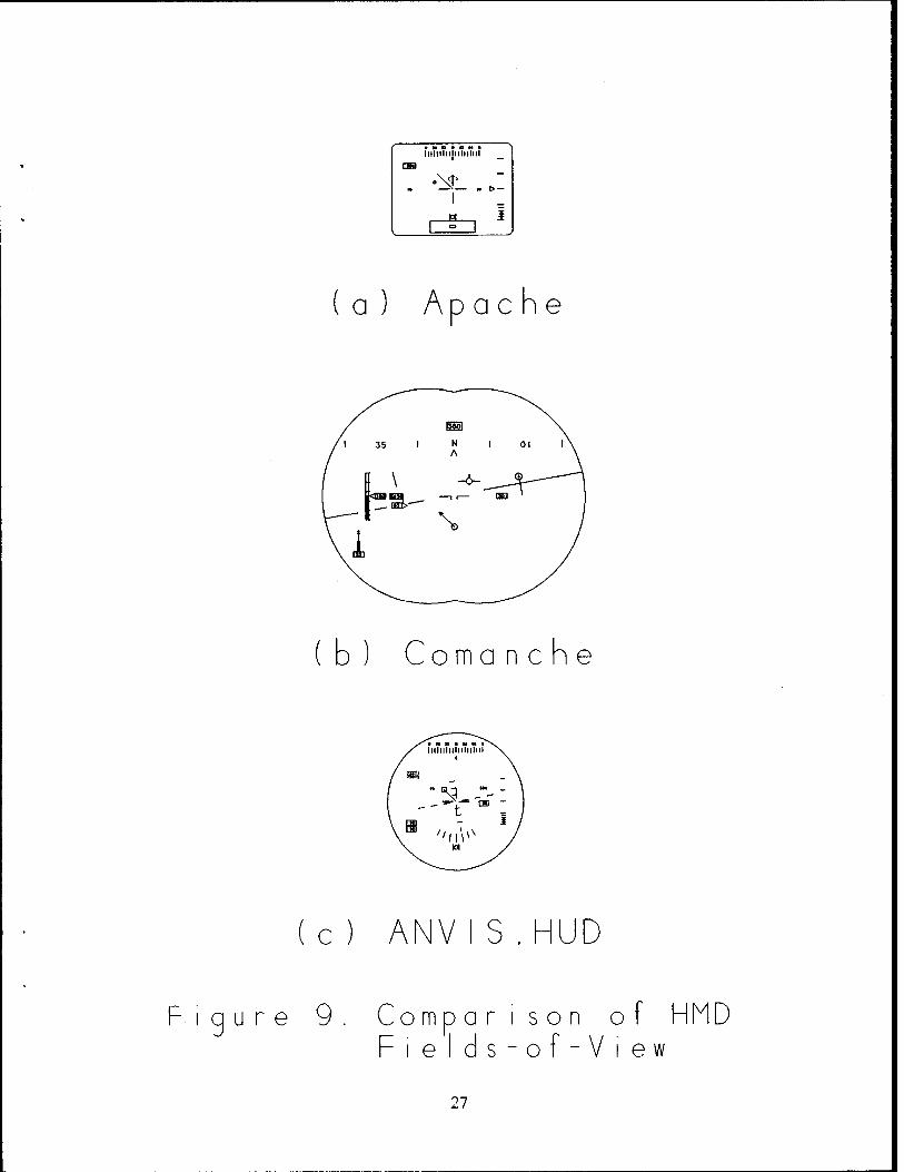
No attempt was made to draw all symbologies (Figures 1 through 7) to the same scale. They are drawn to the same scale for compari- son in Figure 9
(1) Operational HMDs
(a) AH-64 (Apache); The Apache's Integrated Helmet and Display Sighting System (IHADSS) is the only operational HMD in ser- vice today. This is a monocular raster display with embedded symbols. While there is a head-tracker, it is used only to direct the sensor, not orient the display. All symbologies are screen-fixed. There are three operating modes: Hover, Transition, and Cruise(10).
This HMD appears to have been simply adapted from what would have been presented on a fixed HUD.
i General: Altitude is shown both digitally and with a thermometer scale. Vertical speed is shown as a moving caret. All altitude information is on the left. Airspeed is shown digitally on the left.
Aircraft heading is shown as a conventional tape and lubber line at the top of the display. Side- slip information is shown in a ball-bank format at the bottom of the display
A fixed aircraft head-tracker symbol is shown aligned to the aircraft axis. A sensor location within the field-of-regard (FOR) is shown at the bottom of the FOV. This shows a box representing the sensor FOR with a smaller box showing the sen- sor LOS within it.
ii Hover Mode: The Apache hover symbology is shown in Figure 1.
The hover symbology is a screen-fixed plan view (God's eye view) of the scene. The velocity vector is shown emanating from a reticle. There is also an aiding cue (a small circle) showing accelera-
17
tion. The scaling of the velocity vector is full length equals six knots groundspeed.
There is also a station-keeping variant of the hover symbology. In this format, a ground-fixed box is superimposed denoting a fixed hover point. This box is driven by Doppler radar signals.
The transition symbology is similar to the hover symbology, except for scaling of the velocity vec- tor and the addition of the screen-fixed horizon line. The scaling of the velocity vector is full length equals sixty knots groundspeed (i. e., ten times the hover symbology).
iii Cruise Mode; The cruise symbology is a screen- fixed primary flight display and is shown in Fig- ure 2.
(2) Rotorcraft HMDs under Development
It should be emphasized that these systems are still under devel- opment and that these descriptions may or may not match what is finally fielded.
(a) RAH-66 (Comanche); The Helmet Integrated Display Sighting System (HIDSS) is the HMD being developed for the Comanche. It is a bi-ocular display. Portions of the display are air- craft-fixed/ -referenced and portions are world-fixed/-refer- enced.* There are three operating modes. In addition to Hov- er and Cruise, there is also an Approach mode which is not described(24).
It is not clear from Reference (24) how the pitch ladder and pitch symbol are stabilized. We assumed the pitch ladder was aircraft-fixed/world-referenced and that the horizon line was world-fixed. This was confirmed by conversations with pilots who participated in the Comanche simulator trials.
i General: Barometric altitude is shown digitally. Vertical speed is also shown digitally. The verti- cal velocity digits also move vertically to pre- sent an analog indication. Radar altitude is shown both digitally and with a thermometer scale. All altitude information is on the left. Airspeed is shown digitally on the right.
The switching of the airspeed from left to right and altitude from right to left is unconventional and controversial.
* See discussion on stabilization in Section F (page 33)
18
Both an aircraft reference symbol (pitch marker) and a flight path marker (FPM) are displayed. The forward-view FPM is removed with airspeeds below 10 KIAS.
Line-of-sight (LOS) azimuth is shown as a tape with a lubber line at the top of the display. Air- craft heading is shown digitally just above the LOS azimuth tape. Sideslip information is shown as a pendulum at the bottom of the display. Sideslip is blanked below 40 KIAS and will not normally ap- pear in hover.
Torque is shown as a moving index on the left, be- low the altitude display.
ii Hover Mode: The hover symbology (shown in Figure 3) contains a world-stabilized plan view (God's eye view) of the scene.
The velocity vector is shown emanating from a cir- cle. Aircraft acceleration along the velocity vec- tor is shown by an arrowhead which indicates the acceleration. If no acceleration is present, the arrowhead is a "T" at the end of the velocity vec- tor. Acceleration transverse to the velocity vec- tor is not shown.
Nap-of-the-earth (NOE) symbology appears similar to the hover symbology.
iii Cruise Mode; The cruise symbology is a world-sta- bilized primary flight display shown in Figure 4. Both a FPM and an aircraft reference symbol are displayed. The FPM is a pilot's eye view of the trajectory which shows the projected impact point.
The pitch ladder is similar to the F-18, i. e. canted to indicate the direction of the nearest horizon.
(b) ANVIS/HUD: The ANVIS/HUD is an adaptation of advanced night vision systems which adds flight symbology to the basic night vision goggles. The term "HUD" is a misnomer, the sys- tem is worn on the head. The symbology is presented to the right eye only while the imagery (I2) is shown binocularly.
The ANVIS/HUD system is scheduled for implementation in UH- 60, CH-47, UH-1N, and CH-46E aircraft(25). It is also being evaluated for the C-130.
i General: No head tracker incorporated, so all sym- bology is screen-fixed. The airspeed and baromet-
19
ric altitude are shown digitally. Radar altitude is shown digitally and in a tape scale.
Heading is shown as a conventional tape scale across the top of the FOV. A roll scale and sideslip cue are shown at the bottom.
Engine data is shown digitally on the left side. Torque is below and slightly outboard of the air- speed. Engine temperatures are shown with naviga- tion data above and outboard of the airspeed.
A horizon line is present in all modes. A fixed reticle (cross) is also present in all modes.
ii Hover Mode: In addition to the previous symbols, the hover symbology (shown in Figure 5) shows a screen-fixed plan view of the velocity vector.
iii Cruise Mode; The ANVIS/HUD cruise symbology (shown in Figure 6) is similar to the hover symbology with the omission of the velocity vector symbol.
(c) MH-53J: The symbology (shown in Figure 6) was largely de- rived from USAF fixed-wing studies. This was an AFAL demon- stration of their HMD technology for a Special Forces heli- copter (26) .
The significant differences between the MH-53J symbology and others is the roll scale and heading both at the top. Air- speed is shown as an error cue — a vertical tape from the aircraft reference.
It is not clear from Reference (2_6) how the symbols are sta- bilized.
(d) LifeSaver: LifeSaver is a Honeywell system designed to de- tect wires and other obstructions(2_7) . LifeSaver is a generic display for R/W aircraft. The symbology is shown in Figure 8.
Airspeed and torque are shown digitally on the left. Alti- tude is shown digitally and in a tape on the right. The source of the altitude data (barometric or radar) is not specified.
Sideslip is shown at the bottom of the FOV and heading at the top. The aircraft reference symbol is a flight path mar- ker (FPM).
Head-tracker and sensor coverage symbols are also shown.
It is not clear from the description how the symbols are stabilized(27).
20
(e) Comparison; Figure 9 shows Apache, Comanche, and ANVIS/HUD fields-of-view drawn to the same scale for comparison. No information was available for the MH-53J HMD.
(3) Helicopter HUDs
For completeness, there are three head-up displays (HUDs) which have been developed for helicopters. These were developed for the CH-3E (MARS), the AH-1S, and the Bell 230.
(a) CH-3E (MARS) : The CH-3E HUD was developed for the Mid-Air Retrieval Systems (MARS) (20). This was a specialized mis- sion involving in-flight retrieval of reconnaissance drones being parachuted. The symbology is shown in Figure 10.
Airspeed is displayed as a fast/on-speed/slow cue on the left with vertical speed and a pitch scale shown on the right of the FOV. Sideslip is critical to the mission and is shown on the bottom of the FOV.
(b) AH-18: The AH-1S HUD was developed as a weapon aiming sight with limited flight symbology. The center of the FOV con- tains weapon information with engine torque, aircraft head- ing, and radar altitude are shown digitally around the pe- riphery (28.) . The symbology is shown in Figure 11.
The US Marines use a modified HUD with additional flight information. The Marine symbology was not available at this writing.
(c) Bell 230: This HUD was developed for the Chilean Navy as an IFR flight display. It has also been certified by the FAA as a primary flight display. The symbology was developed from the fixed-wing HUD installed in the Beech King Air(29). Ver- tical tapes for engine torque and engine temperature were added on the left and right side of the FOV. The symbology is shown in Figure 12.
(4) Proposed Fixed-Wing HMDs
(a) Air Force Armstrong Laboratory (AFAL): A baseline HMD sym- bology used by AFAL is shown in Figure 13(19).
Airspeed and altitude are shown digitally on the left and right side respectively. Vertical speed is shown as a fixed tape/moving caret inboard of the altitude.
Heading is shown as an abbreviated scale at the top. A non- conformal attitude scale is shown at the bottom.
(b) Theta: The Theta display (shown in Figure 14) was developed by Geiselmann and Osgood (30) and uses a pitch sphere sym-
21
bology to maintain attitude awareness on the part of the pi- lot.
Airspeed is shown digitally on the left side. Altitude is shown in a counter-pointer on the right side Vertical speed is shown as a tape scale inboard of the altitude.
Heading and altitude are shown in an attitude ball at the bottom of the display FOV.
(c) McDonnell-Douglas; A "typical" HMD symbology was described by Adam (31) and is shown in Figure 15.
This display is distinguished by a non-conformal "basic T" symbology set at the bottom of the FOV with airspeed, alti- tude, heading, and pitch.
A tape scale at the top shows pilot LOS azimuth. LOS eleva- tion is shown digitally above the azimuth tape.
A "performance data block" to the left of the aiming reticle shows Mach number, angle-of-attack, and normal acceleration.
(d) ANVIS/HÜD; The symbology developed for the ANVIS/HUD for the C-130 is shown in Figure 16 (32.) .
Airspeed and altitude are shown digitally in the upper left and upper right of the FOV. Radar altitude is shown as a vertical tape (moving caret) on the left, below the air- speed. Digital radar altitude is boxed below the tape.
Heading is shown as a conventional horizontal tape scale with the digital heading shown beneath it. A waypoint caret indicates the heading to the next waypoint.
The pitch ladder and aircraft reference symbol are displayed in the center with a bank scale beneath. A sideslip "ball" is shown at the bottom of the FOV.
Vertical velocity is shown as an arc with a moving caret em- ulating the panel instrument. Engine torque is shown as a circular scale as well. Both are located below the baromet- ric altitude digits on the right side of the HUD FOV. Engine torque is below the altitude digits with vertical velocity at the bottom.
Navigation data, master warning, and threat warning are also displayed in the upper center, lower right and bottom of the FOV.
22
HEADING
TORQUE
ACCELER- ATION
AIRSPEED
RETICLE
SIDESLIP
SENSOR REFERENCE
VELOCITY VECTOR
ALTITUDE »DIGITAL)
VERTICAL SPEED
ALTITUDE IANALOG)
HEAD TRACKER REFERENCE
Figure 1. Apache Hover Symbology
HEADING
TORQUE
AIRSPEED
RETICLE
SIDESLIP
SENSOR REFERENCE
HORIZON
ALTITUDE (DIGITAL)
VERTICAL SPEED
ALTITUDE (ANALOG)
HEAD TRACKER REFERENCE
Figure 2. Apache Cruise Symbology
23
IDS AZ1WJTH
VERTICAL VELOCITY
VELOCITY VECTOR
Figure 3. Comanche Hover Symbology
LOS AZIMJTH
VELOCITY VECTOR
PITCH LACOER
Figure 4. Comanche Cruise Symbology
24
HEADING
ENG TErtPS
AIRSPEED
TORCUE
ROLL SCALE
SIDESLIP
VELOCITY VECTC
BARO ALTITUDE
RADAR ALTITUDE
PITCH LADDER AND HORIZON
Figure 5. ANVIS/HUD Hover Symbology
NAV DATA
ENG TErtPS
AIRSPEED
TORQUE
ROLL SCALE
SIDESLIP
HEAOING
BARO ALTITUDE
RADAR ALTITUDE
PITCH LADDER AND HORIZON
Figure 6. ANVIS/HUD Cruise Symbology
25
HEADING
BANK SCALE
AIRSPEED ERROR CUE
RADAR ALTITUDE
PITCH LADDER
Figure 7. MH-53J Symbology
HEADING
AIRSPEED
TORQUE
VELOCITY VECTOR
ALTITUDE (DIGITAL)
VERTICAL SPEED
HEAD TRACKER
ALTITUDE (ANALOG)
Figure 8. LifeSaver Symbology
26
■ w n ■ « M ■ IllhllMjllllllllI
CSS
- •NIL .,: i n *
. 1 ° 1
(a) Ap a c h e
(b) Coma n c h e
(c) ANVIS.HUD
Figure 9 Comparison of HMD Fields-of-View
27
Roll Cu«
Air«p««d Cue
Aiming ^-* Symbol
F
S
\W|'//
A +-
\ ^^. Moelzon
— — 6 ^.Vertical — = a" Sp««d
7 C5
-~^ Pitch Reference
\ Sides 1lp
Figure 10. CH-3E (MARS) HUD Symbology
Torque
Heeding
Range La Target
Aim)ng Reticle
Altitude
Figure 11. AH-1S HUD Symbology
28
L»ft End!«» 3<73? 754>fc T*«p*rafur« ~'~W
WJ ——^— E
3 IIT T Z. ^™ Co«»«» ——n— * *' I * „
Right Ettjln» T*ip*ratur«
Co«».» Dtviat i
Mr* »MUI Pal«f»r
Hotor Tor«,»» "
Col Uct ivt Cm
A
.160
I l,T,l ,T -7
Altilnd» Pol»l»r-
taroMtrIc AltiKoV
talk teal*
Hauling
Figure 12. Bell 230 HUD Symbology
29
AIAING RETICLE
AIRSPEED
HEADING
ALTITUDE
VERTICAL SPEED
ATTITUDE
Figure 13. AFAL Symbology
Al/UNG RETICLE
AIRSPEED
ALTITUDE
VERTICAL SPEED
ATTITUDE WITH HEADING
Figure 14. Theta Symbology
30
PERFORAANCE ' " DATA BLOCK
AIRSPEED
HEADING
LOS ELEVATION
LOS AZIAUTH
AIAING RETICLE
ATTITUDE
ALTITUDE
Figure 15. McDonnell-Douglas Symbology
HEADING
PITCH LADDER
AIRSPEED
RADAR ALTITUDE
BANK SCALE
WARNING
BARO ALT
ENGINE TORQUE
VERTICAL SPEED
NAV DATA
SIDESLIP ENG FAIL
Figure 16. C-130 ANVIS/HUD Symbology
31
F SYMBOLOGY STABILIZATION
(1) General Comments
Prior to the advent of see-through displays, flight displays were fixed in the cockpit. There was little need to create a display format which remained fixed in its orientation as the aircraft maneuvered.
The HUD, with its ability to place display symbols directly over- lying the real world image, required the display designer to keep some symbols fixed relative to these real world cues. Many HUD symbols are corrected for aircraft motion — the FPM, the horizon line, target symbols, to name a few.
With the HMD, the display itself can move. As the pilot's head moves, the display orientation changes. Some cues, particularly targeting cues, must be corrected to compensate for both aircraft motion and pilot head movement.
We have already mentioned the Apache's hover symbology which com- pensates for aircraft orientation, but not for pilot head move- ment. As long as the pilot looks forward, the display correctly indicates the aircraft velocity relative to the direction the pi- lot is looking. However, when the pilot moves his head, the orientation of the display does not agree with the relative di- rection of pilot line-of-sight (LOS) is incorrect. The display shows left/right and fore/aft motion relative to the aircraft nose, not the direction of the pilot's LOS.
More critical is the presentation of the horizon line. In the Apache, the horizon line is presented conformal to the real hor- izon only if the pilot is looking forward with his head level. If he looks to the side, it still registers the bank as if he were looking forward. More critical, if the pilot looks up, the horiz- on moves with his LOS indicating obstruction clearance where there may be none!
The first requirement is to be able to describe symbology stabi- lization. That is, we must be able to define various char- acteristics.
A number of definitions have been proposed to describe how sym- bols are stabilized. These can be found in the HUD/HMD Glos- sary (12.) prepared as part of this study (attached as Appendix A).
(2) Coordinate Systems
Several coordinate systems are present with flight displays. These systems, defined in Appendix A, are world coordinates, air- craft coordinates, head coordinates, display coordinates, and screen coordinates.
33
We normally consider orthogonal coordinate systems, although other coordinates, such as polar coordinates, could be used. Gen- erally, the sign convention is positive forward, right, and down.
(3) Symbol Orientation
(a) Definitions: The term "reference" has been adopted to indi- cate how a symbol has been rotated to compensate for mis- alignment between the world, aircraft, and display coordi- nates .
World-referenced means that the symbol is rotated to compen- sate for differences between display coordinates and world coordinates. These differences could be caused by aircraft motion or, in the case of HMDs, by pilot head motion.
Aircraft-referenced means that the symbol has been rotated to compensate for misalignment between display coordinates and aircraft coordinates. This would be caused by head move- ment and only applies to HMDs.
These compensations are normally thought of as accounting for misalignment of all three axes. In fact, they are often applied to one or two axes only such as roll-referenced sym- bols.
(b) Examples: The Apache symbology is screen-referenced and screen-fixed. That is it does not correspond to the direc- tion of the pilot's LOS. Figure 17 (a) shows the effect of this on various views from the pilot station. In the figure, the helicopter is drifting forward and to the right at a 45° angle to the north heading. The figures show the view as the pilot looks forward, to the right at relative angles of 45°, and 90° to the right.
Haworth and Seery evaluated a world-referenced Apache hover symbology(33). In this symbology, the aircraft velocity vec- tor rotates to match the aircraft heading. Figure 17 shows the difference between screen-referenced and world-refer- enced symbols clearly.
(4) Symbol Location
(a) Definitions: The term "fixed" has been adopted to indicate that the location of the symbol has been moved (on the screen) to compensate for aircraft/head motion and allow the symbol to overlay a cue in the external visual scene.
World-fixed means that the symbol is rotated/moved to com- pensate for aircraft and head motion. Aircraft-fixed means the symbol has been rotated/moved to compensate for head movement only. Screen-fixed means that no compensation has been applied.
34
The term "stabilized" should be avoided since it has two meanings in earlier work. "Roll-stabilized" has been used to mean "roll-referenced". "World-stabilized" has meant "world- fixed" .
It is entirely feasible for a symbol to be world-referenced and screen-fixed. Such a symbol is the horizon line on the Apache HMD. Its reference point is fixed in the center of the display, but moves vertically to indicate aircraft pitch and rotates to indicate aircraft bank. This is shown in Fig- ure 18 (a).
(b) Examples: Figure 18 shows the Apache symbology overlaying a stylized real-world scene. In this figure the transition symbology is shown with a horizon line. Figure 18 (a) shows the standard Apache symbology with a screen-fixed, but world-referenced horizon line. Note that the horizon does not overlay the real horizon when looking off-axis (or when looking up or down).
Haworth and Seery (33) also examined world-fixed horizon lines. As shown in Figure 18 (b) , their modified horizon line is world-fixed in that it moves to indicate the loca- tion of the real horizon. In this case, the horizon line overlays the real world horizon and correctly indicates ob- jects at the same elevation as the aircraft.
The Comanche cruise symbology shows a world-fixed horizon with an aircraft-fixed/world-referenced pitch ladder, shown in Figure 19. Note that the aircraft-fixed pitch ladder dis- appears from the FOV as the pilot turns his head off-axis. The world-fixed horizon line remains in the FOV (provided the pilot's LOS is horizontal).
(c) Discussion: A world-fixed horizon line (and elevation lad- der) can be used to maintain situational awareness and pro- vide information about the relative elevation of targets and obstructions. It appears to provide insufficient cues to al- low for flying the aircraft, although definitive experiments have not been performed.
A screen-fixed horizon symbol can be used to provide air- craft flight information (at least in fixed-wing aircraft), but provides misleading elevation cues. The fixed-wing HMDs avoid these misleading cues by not attempting to make the horizon line appear conformal, i. e. by compressing the sym- bol.
35
/ i i i \tm
A
-— * 8—
^ • 1 , X— o * —
a
1 *
1 1 1 IIM41 A
"— * t=
;r 7j- « S— o
D
1 «
1 1 1 |I*H A
\
"— s s—
S— o
¥1
V )
o I
O
s—
T 71'
|l**|
s a
o _Q £ >^
CO
(■ s
CD 1 1 1 A
|IH*1
.^" U 0) c s=
%
0) 3— | a in s_ ■■Er- - I - 5 •t 2— c
"O CD **= 1
o t t p ~ <v I
cc i
§ 2
>
CD CD L
u CO s
i i i IIH+1 A " -
<D o s-5 S
a
o s-E o
1 - 2 Ol
s— 1
-& o •— <u I e •
V
in
o
_Q
en O O —
— -TJ O O
E O E
CO i 00
"a CD ~0
u CD CD a L. O <D <J <=
Q) CO 0 L_
<D • CD Cd [\ <-<-
TD — CD
cn t_ CD i O s- ~T3
cn O
LL
36
c \ / "\ 1 I1 ll ' vm
\T "— *r *- \\ »i IV »= r «= \ ■—
0 l
^ \\A
f 1 ' \ 1 1 IIH+I
\A
m— s t— \ 3— | —
— 1 » —
1
m —
0 \
\
o
-D O
in
o X
o
<D
X
<D
c O N
1_
o
o x
c CD <D i_ o
CO
f \\ / "\ i i L '\\m
*— h 3i if r—
ill 1 tt
s— \ \ »— K/X
0 ^ 1\\/J
i i i A
r '
"— s t— 3= 1 »i 1
~> JL
0 ^ V s !
X
<D c
_J
c O N
♦» ■ —
l_
o IE
in T>
TJ d> o CD
I X
LL
~o
o
~o a >- O cn
O
cz O <D _Q <D E L_ >- O CO
CO ID
• CD CO X
LL Q) i
L_ ~o ZJ — CHL_
■ — o
37
■»<
\
\ rj/
en O
O _Q E
_c CO
0) ■ —
en O r5
h- i_
c (J a» o
CO Q) _c
O Ü
cn c: O D O E E O
CO o
cn
38
6 HMD LESSONS LEARNED TO DATE
(1) Training
The Apache training unit at Fort Rucker report Apache student pi- lots require a fairly lengthy period (of the order of twenty-five hours) to adapt to the HMD(34>) • The conflicting motion cues be- tween the symbology and the IR cue were cited as contributing to this.
Several anecdotal reports were made of students who were ex- tremely reluctant to move their heads while hovering using the IHADSS for reference.
The instructor pilots (IPs) generally did not criticize on the orientation of the symbology during hover. The did, however, com- ment unfavorably on the difficulties with relating it to the in- frared image. To quote one pilot, "IR sucks."
The syllabus consists of about 12 hours of contact flying fol- lowed by the instrument/night portion. There is apparently no doctrine on when to introduce the use of the IHADSS. One IP says that he encourages, but does not insist, on the student's use of the HMD. He felt that students who used the HMD during the con- tact portion of the syllabus had less trouble during the instru- ment/night portion.
One IP reported, anecdotally, that Apache pilots who don't fly for a month or two appear to have lost the ability to fly using the IHADSS and must be essentially retrained. It is also reported that new Apache pilots are only minimally qualified upon arrival at their units and require extensive further training.
The difficulty of using a monocular display was downplayed by all pilots. They cited some advantages with a monocular display as well as some disadvantages. One pilot (who wears glasses) com- mented that the eye relief is too short for use with glasses. He reported an inability to see the entire FOV of symbology.
Additionally, there are reported difficulties because of drifting of the hover box.
(2) Operations
Operationally, there are reported difficulties because of the differing motion cues for the IR image and the symbology and the need to correlate the God's eye view (based on aircraft heading) with the pilot's eye view (based on direction of sight). The ma- jor problem is combining symbol/image cues, not necessarily with the symbol reference.
The lack of conformality of the horizon line with the real world horizon presents misleading elevation cues. This creates a hazard because the horizon cue as shown does not compensate for pilot
39
head motion and the pilot may conclude he has adequate obstacle clearance when, in fact, he has none.
The US Army Safety Center (USASC) studied a variety of potential- ly hazardous visual problems associated with the use of night vi- sion devices (NVDs) (3_5) . While most of these incidents involved ANVIS, Apache pilots reported some problems. Incidents occurred during all phases of flight, but were generally found during good weather, over open desert terrain, and periods with limited ambi- ent illumination. Degraded visual cues were the most common re- port with loss of visual horizon and degraded resolution most frequently mentioned.
The USASC has summarized all Apache accidents in a briefing(36). A common accident scenario is the inability of the pilot to de- tect drifting during hovering operations or an inability to esti- mate distance to obstructions, such as trees. Another frequently mentioned accident scenario is misjudging obstruction height or the inability to detect slow descent during hover and low-level flight.
(3) Research
(a) Rotary Wing: Haworth and Seery evaluated the effect of world- versus screen-stabilization on Apache hover symbol- ogy(33). Their results indicate that neither the standard Apache nor the world-referenced version were satisfactory in recovering from a drifting hover to a stabilized hover. The world-referenced version did provide a better reference for spatial awareness tasks.
NASA has sponsored a number of studies to determine the min- imum visual cues for satisfactory rotorcraft flight. These studies include both simulated ground texture and symbol- ogy(37-38) .
NASA-Ames has studied the effect of scene texture reduction on the ability of the pilot to fly by reference to the ex- ternal visual scene. This has implication for the required resolution for HMD raster images. The results indicate that the absence of resolution (specifically high frequency con- tent) in the scene can be partially compensated for by HUD symbology. The symbology did interfere with the visual scene information(39).
Other NASA studies examined the trade-off between field-of- view (FOV) and visual scene. A reduction in FOV degrades pi- lot/aircraft performance, but the actual trade-off is not clear(40-41)•
One pilot who participated in the Comanche evaluations re- ported mixed reactions to the hover symbology. He felt the Apache's reticle symbol conveyed aircraft drift better than the Comanche • s circle (34) . He also felt that the Apache' s
40
acceleration cue was much more useful. The Comanche's accel- eration cue only provides information concerning acceler- ation along the velocity vector axis and does not include any transverse acceleration.
He did comment favorably on the world-stabilization of the Comanche's hover symbology.
It would be desirable to review the results of the symbology studies conducted for the Comanche development. These were not available because of proprietary restrictions. The in- ability to review this report restricts the observations that can be made in this section.
(b) Fixed-Wina: Armstrong Laboratory (AFAL) has been evaluating several HMD symbologies. While the results are preliminary, incorporation of a screen-stabilized attitude display with no attempt at conformality appears satisfactory for F/W weapons delivery (both air-to-ground and air-to-air). Re- duced FOV did have an adverse effect(19, 42-44).
These studies have not included low altitude flight, how- ever. Nor have they considered hovering or NOE flight
(4) Observations
The following observations are presented as first impressions. They have not been tested, but should be considered as an initial "expert opinion" regarding HMD symbology.
(a) Information Requirements: The first question to be asked is why is an HMD needed? Considering up-and-away flight, the obvious answer is to allow the pilot to view targets or ob- structions located off-axis.* If this is the only require- ment, then the flight information presented should be de- signed to allow the pilot to maintain control while looking for a target, not fly the complete mission.
This seems to lead one toward screen-fixed displays. Initial impressions suggest that screen-fixed symbols allow the pi- lot to maintain control while looking off-axis. Thus there is a place for the much less expensive screen-fixed dis- plays, such as ANVIS/HUD.
In addition, the pilot may require estimation of elevation, or at least of the local horizontal. The use of a conformal, world-fixed horizontal reference line is useful for this in- formation task. It is not, however, useful for controlling
While this answer may seem obvious, the question is not. One should always ask why a display is need. During a recent HUD meeting, the question was asked why a sensor image was needed for low visibility landing. No one at the meeting had an answer other than "We need one".
41
aircraft attitude. (It may be useful in maintaining an air- craft attitude briefly.) This argues for two types of hori- zon reference: a conformal, world-fixed zero-elevation cue and a screen-fixed aircraft control cue. The latter cue would probably best be drawn as a compressed symbol with no attempt to make it conformal.
During NOE or hoverf this may not be true. Observations by Fort Rucker Apache pilots suggests that the problem is not so much with the symbology as with differing motion cues presented by sensor images and symbology.
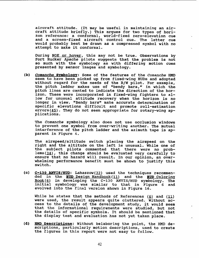
(b) Comanche Symbolocry: Some of the features of the Comanche HMD seem to have been picked up from fixed-wing HUDs and adopted without regard for the needs of the R/W pilot. For example, the pitch ladder makes use of "bendy bars," in which the pitch lines are canted to indicate the direction of the hor- izon. These were incorporated in fixed-wing fighters to al- low for unusual attitude recovery when the horizon is no longer in view. "Bendy bars" make accurate determination of specific elevations difficult and promote roll-estimation errors(45). They do not seem appropriate for rotary-wing ap- plications.
The Comanche symbology also does not use occlusion windows to prevent one symbol from over-writing another. The mutual interference of the pitch ladder and the azimuth tape is ap- parent in Figure 4.
The airspeed/altitude switch placing the airspeed on the right and the altitude on the left is unusual. While one of the subject pilots commented that there were no prob- lems (34.)/ this change should be evaluated very carefully to ensure that no hazard will result. In our opinion, an over- whelming performance benefit must be shown to justify this switch.
(c) C-130 ANVIS/HUD: Lahaszow(32) used the technigues recommen- ded in the HUD Design Handbook (11) and the HUD Coloring Book(6) in developing the C-130 ANVIS/HUD symbology. The initial symbology was similar to that in Figure 6 and evolved into the final version shown in Figure 16.
While he states that the methods of References (6) and (11) were used, the result appears quite cluttered. Without ac- cess to the details of the development study, it would seem that the informational requirements were studied, but not the details of specific symbols. It should be mentioned that the display test and evaluation has not yet taken place.
(d) HMD Descriptions: Without belaboring the point, the HMD de- scriptions, particularly motion descriptions, used to create the figures in this report were not easy to follow.
42
H RESTATEMENT OF THE PROBLEM
The problem is the use of inappropriate symbology in helmet- mounted displays. However, simply stating "inappropriate symbolo- gy" is to address the symptoms, not the root cause.
The underlying causes are (1) the absence of a logical, organized design methodology and (2) the absence of test and evaluation criteria.
The result is fielded HMDs with unstabilized symbology which pre- sent cues in conflict with sensor imagery and which can actually lead the pilot into unsafe conditions. This also results in ex- cessive training reguirements.
A design criteria document for HMDs is needed. This should follow the general outline of the present head-up display design guide(JL!) with the addition of HMD-specific sections.
43
I THE HELMET-MOUNTED DISPLAY DESIGN GUIDE
What is needed is a design criteria handbook that replaces the two present design approaches to display development: TLAR* or a slavish adherence to a standard. It is essential that a rational and effective design procedure be prepared.
(1) Previous Design Documents
Several reports and papers have been written examining the over- all display design problem. In chronological order, these are Jenney and Ketchel(4), Singleton(3.), Buchroeder and Kocian(46) . Gard(47), Weintraub and Ensing(48), Hughes(6), Newman(11). and Rogers and Myers(50).
Jenney and Ketchel(4) reviewed the informational requirements of electronic displays in 1968. They outlined the general need for an informational requirements study and reviewed sixteen such studies. They charted the information requirements for each study and summarized them for selected phases of flight (takeoff, en- route, and landing). In their review, the needs of the pilot were assumed to be proportional to the number of times in each data item was mentioned — a vote base. Jenney and Ketchel do mention that such a summation is no substitute for a detailed analysis, but only as an approximation of the needs.
As an example, Jenney and Ketchel mention a pull-up warning to avoid terrain. This was only listed twice (out of sixteen re- ports) , but is obviously an important information item. This points out a major limitation of pilot surveys or summaries in determining informational requirements and the need for careful consideration of all relevant issues.**
Singleton(3.) described a generic approach to display design. The basic questions to be asked during the information requirements portion of the analysis were listed previously (page 2). Single- ton recommends (1) Justifying the display need; (2) Determining what data is required; (3) Ensuring that an average pilot can use the display; and (4) Ensuring compatibility of the display with the environment and pilot.
Buchroeder and Kocian(4_6) reviewed the design trade-offs for a helmet-mounted display for the Army's Light Attack Helicopter. The study concentrated on the optical and physical integration issues.
* TLAR = That looks about right. ** Jenney and Ketchel mentioned sideslip information and con-
cluded that it was of limited importance to fixed wing air- craft. This may reflect a large proportion of fighter air- craft in their survey sample. It may also reflect no thought for engine-out control.
45
Gard(47) reviews installation characteristics of many HUDs, con- centrating on the optical design. Gard's book concentrates on single-seat fighter HUDs and is a good background volume for a HUD designer although it doesn't qualify as a design guide.
Weintraub and Ensing(48) reviewed the human factors issues in- volved in HUD design. Their review concentrates on human visual performance and related topics, such as cognitive sharing.
Hughes(6) outlines many symbology considerations for HUD design- ers, again primarily for single-seat fighter aircraft. Hughes concentrates on symbology issues, not the informational require- ments. He does stress the need to minimize the scene content to allow sighting of external targets. Hughes stated the principle that every pixel must improve mission performance (Hawkeye's Law, see page 5)
Newman(11) prepared a HUD design handbook which was the result of two Air Force sponsored HUD studies to develop generic specifica- tions for head-up displays. The study concentrated on symbology and systems integration issues and drew heavily on lessons learned from past programs. Newman also recommended a detailed informational studies (adapted from Singleton) and called for a logical test and evaluation protocol which was adapted from Ha- worth and Newman(49).
Rogers and Myers (.50) have developed an expert system approach to display design. This system, ACIDTEST, is designed to provide support for the display designer. The system provides guidelines to the designer to ensure all informational requirements have been considered. It also lists display "rules" and guidelines. Where conflicts exist, the system identifies these to the de- signer. ACIDTEST has not been used at this writing.
What is really needed is a combination of the systems integration of Newman(11); the informational studies of Jenney and Ket- chel(4), Singleton(3.) , and Newman(11) ;, the optical design of Gard(47) or Buchroeder and Kocian(46); and the test/evaluation protocol of Newman(11) or Haworth and Newman(49).
(2) Strawman HMD Design Guide
A strawman HMD Design Guide outline has been developed using the HUD Design Handbook as a pattern. The outline is attached as Ap- pendix C.
There are a number of outstanding issues for which additional re- search is required, these are outlined below
I Symbology Issues:
Symbology stabilization for hover/nap-of-the-earth flight for up-and-away flight
46
Display of aircraft control symbols off-axis off-axis horizon line off-axis pitch (elevation) ladder
Display of LOS azimuth and aircraft heading Airspeed and altitude Symbology combined with raster image
clutter differences in relative motion
An initial review of the symbology issues indi- cates that the hover symbology (both format and stabilization) requires a research and development effort including flight/simulation experiments.
The up-and-away symbology (at least our initial impression) is less critical. The fixed-wing re- sults to date indicate that a non-conformal, screen-fixed attitude display may be satisfactory. This must, however, be confirmed for low altitude and NOE flight.
The display of off-axis pitch/elevation/horizon information requires a solution. The horizon line is used for two purposes. One is as a reference for aircraft control. It is also used to estimate the elevation angle of objects. Off-axis, these two purposes conflict. A screen-fixed horizon line assists the first purpose, a conformal horizon line serves the second. The issue is how best to display horizon information off-axis.
The display of pilot's LOS azimuth and heading in- formation has not been resolved. There are con- flicting requirements. To maximize aircraft con- trol, an aircraft heading tape seems to be pre- ferred; however, it may be easier to locate a tar- get using a tape showing azimuth. This has not been resolved in either F/W or R/W HMDs.
While the choice of displaying airspeed on the left and altitude on the right or vice versa was resolved for head-down displays many years ago, researchers continue to develop reversed displays. It is essential that the rationale for such a dis- play choice be thoroughly documented prior to in- troduction into service. The experiments to sup- port this rationale must be clear and conclusive.
The symbology must be examined both with and with- out a backup raster image. Symbology clutter can impact negatively on the raster image. Apache pi- lots report the differences in relative motion be- tween the image and the screen-fixed symbology is confusing. The implication is that the raster is
47
interfering with the symbology — the symbology should be aiding the image interpretation.
II Optical Issues;
Field-of-view requirements Need and amount of binocular overlap Resolution requirements for imagery Symbology combined with raster image
registration differences brightness differences
Need for color
The helmet display must be examined to determine the trade-off in performance as various optical parameters are degraded. All of these requirements are "good" — large FOV is good, high resolution is good, etc. The question is how good is good enough and is the cost worth it.
There is limited information about where the "knee of the curve" is on the performance improvement as, say, field-of-view is increased. Experiments must be conducted to obtain this data. Without this type of data, the designer and the procure- ment officer have no way to determine if a speci- fication is reasonable.
(3) Database Development
It would be extremely valuable to develop a database dealing with the various HMD systems and symbologies. This development should be started as soon as possible while the amount of data is still small.
The difficulties associated with the additional degrees of free- dom of the display makes the use of electronic multimedia-based databases quite attractive. This would allow the symbology to be displayed on a screen showing the effect of aircraft motion and orientation and of pilot LOS. Figure 20 shows a proposed database arrangement.
The material to be included under the major headings is similar to those developed in the HUD Design Handbook and will for the HMD Design Guide. The definitions should include keywords with which to cross-reference the various groups.
In addition, the "display modes" for different aircraft should be easily cross-referenced from one system to another. The displays should also be cross-referenced with the information and stabil- ity requirements.
It would also be quite beneficial to use a multi-media capability and show actual sensor images and the corresponding stroke sym-
48
Army and other civil & military organizations
Systems Sensors
bology. The database user could "maneuver" the aircraft to view the effect of different aircraft attitudes and head positions.
It is recommended that such a database be developed during Phase II of this program.
0 1 3Top Level3 3 Menu 3
Ä Ä ÜÜ 1 A ' Definitions Ä— List of keywords 3 A 0
A 'DocumentationÄ— Regulations, Criteria, 3 £ 1) and Specifications for 3
3 Ö L
A ' Hardware Ä— Hardware 3 A Ü
\ tJ • A ' software Ä— S/W Criteria 3 A 0 3
ü 1 A ' Display Ä— Symbology — 3 £ 0 3
3
ü 1 Ä ' Information Ä— Required data
3 Stabilization3 Literature review 3 and Ä 1 3 Requirements3 3
Ä 0 Cross-referenced by flight task
Ü 1 Display Ä 0
3 Formats Ä Ä Ä 0
ö A 1 V/STOL R/W F/W
tj A 1 Apache Comanche Other
3 3 3
A— Cross-referenced Ü by display mode
Raster Static Dynamic
3
3
3
3
3
3
Ä-
"c C R 0 S S R E F E R E N C E D
B Y
K E Y W 0 R D S 3
-0
Figure 20: Proposed Database Arrangement
49
J POTENTIAL BENEFITS
As helmet-mounted display (HMD) technology matures, HMDs will be found on more and more aircraft. For the military, HMDs offer significant advantages in terms of off-boresight weapon delivery. For both civil and military operators, the HMD will enhance safe operations when maneuvering in close proximity to obstacles in conditions of reduced visibility.
(1) Reduced Design Cost
By developing a more rational and effective design procedure, de- velopmental and evaluation costs will be reduced since the de- signers will make use of the historical knowledge gained in the development and fielding of similar systems.
In addition, proper information requirements analysis can lead to lower cost systems which are effective by avoiding unnecessary design features which are not supported by defined needs. Exam- ples from the fixed-wing HUD community are the use of inexpensive air-mass HUDs in place of more expensive inertial HUDs for execu- tive and trainer aircraft.
(2) Civil Operators
A recent FAA-sponsored conference (ELVIRA) produced many presen- tations on the advantages of improving the capability of civil helicopters to operate at austere sites in non-visual condi- tions. (51) Emergency medical service (EMS) helicopters could greatly benefit from these displays. Three EMS organizations at- tended the ELVIRA conference; these three companies operate over 700 EMS helicopters. NVGs have been studied as a means to assist these operators, but questions of civil certification have blocked widespread use in the civil community.
In addition to the EMS community, civil law-enforcement depart- ments can make good use of the sensor capability of HMDs.
(3) Military Operators
Improvements in HMD design technology can certainly improve oper- ational mission effectiveness and improved flight safety. However a more significant benefit will be overall reduced costs.
A second, perhaps more significant, savings will be reduced training requirements. The present training costs for Apache pi- lots are excessive. A more-user friendly HMD interface would per- mit pilots to checkout in less time. This would allow them to be- come mission-ready in a shorter time. At the same time, recurrent training costs should be reduced. There should no longer be as rapid a loss of proficiency with time not flying as happens now.
51
(4) External Load Operations
Since the HMD can display sensor images even if the aircraft structure is in the pilot's LOS, there may be a benefit for ex- ternal load operations. The pilot can look down and actually see the sling load using, for example, a television camera. This could reduce the number of crew required. Some external load he- licopters carry a special pilot station just for the pick- up/drop-off phases. A HMD could eliminate this need.
(5) Other Uses of HMDs
In addition to aviation applications, HMDs have been proposed to assist operators of tele-robotic systems. A helmet-mounted dis- play can be used to provide a television (or other sensor) image of the remote operation. As with aviation operations, embedded symbology may be required to augment the imagery.
Applications of this technology were studied for the space sta- tion by Radke and others.(52) Four unique benefits to head- mounted displays were identified: private viewing, head-tracked display, hands-free operation, and an additional display surface. Fourteen candidate space station applications were identified.
The use of head-mounted displays has been proposed as a means of providing simulation images.(17) Such an approach could reduce the cost of visual scene generators for simulators and could cer- tainly allow for smaller systems. In particular, the use of a head-mounted virtual reality display could be used as a simula- tion tool for operational squadrons. The use of HMDs could permit training facilities at operating locations or on-board ships.
52
K RESULTS AND RECOMMENDATIONS
(1) Results
This report is the final Phase I report. The goal of Phase I was to identify major issues and present limitations for helmet- mounted display symbologies and to identify new symbology con- cepts for future HMDs.
(a) Review HMD Symboloqies and Implimentations: Current and pro- posed HMD symbologies and installations were reviewed in Sections D through G. The current Apache symbology has re- sulted in a number of operational problem areas (discussed in Section G. Unfortunately, the proposed Comanche symbology does not appear to be able to solve these problems.
(b) Outline Strawman HMD Design Guide: Based on a review of present state-of-the-art, a number of issues regarding sym- bology and image requirements, such as tradeoffs between FOV vs. image resolution, contact analog vs. abstract symbology, and the need for conformality. Operationally the main issue is how to present off-axis flight control information.
A organization of a HMD Design Guide is presented in Section I. This handbook should contain a design methodology coupled with test and evaluation criteria. The Design Guide is out- lined in Appendix C. The Design Guide should make use of an electronic database described in Figure 20.
At this writing, no clear choice of HMD symbologies can be selected as the baseline for future HMDs. In the absence of such a clear choice, the Apache format should be used as the starting point for future research. Specific issues requir- ing resolution are described on pages 46 to 48.
(2) Recommenations
A program will be proposed to develop a design guide for helmet- mounted displays for rotorcraft which will be suitable for both military systems and for civilian helicopters. A database of HMD systems and symbologies will be incorporated as part of this pro- gram. The use of a multi-media electronic database will be pro- posed.
A series of developmental experiments are proposed to design sym- bologies suitable for low altitude, NOE, and hovering flight. A protocol for test and evaluation of symbology should be documen- ted.
(a) Objectives: The objective for the proposed program is to de- velop a design methodology coupled with a test and evalua- tion criteria. The result will be a design handbook which can be used in conjunction with the Aeronautical Design Standard (ADS). This design handbook will incorporate a pro-
53
cess known to be successful and which makes use of the les- sons learned from past programs.
The design handbook should make use of an HMD database which will make these "lessons learned" easier to see. This data- base will be developed using software similar to HyperCard, but compatible with PC operating systems.
(fc) Creation of a Helmet-mounted Display Database: An HMD data- base should be developed in a format suitable to use on a PC computer. This database should include the following areas:
0 HMD concepts (such as stabilization 0 Glossary of HMD terms 0 Description of existing/planned systems
o Head/helmet components o optical characteristics o sensor descriptions o physical packages o software descriptions o symbology
0 Bibliography of the HMD literature
The descriptions of existing/planned systems should include entire (i. e. complete) systems, such as IHADSS, as well as individual components, such as proposed helmet/display hard- ware .
The database should include the effect of mission/flight phase on the symbologies and other topics (if appropriate).
The development of this database should be coordinated with similar programs to ensure maximum ability to interchange data.
(c) Symbolocry/Image Requirements: Based on a review of present and on-going display research, simulation and flight experi- ments should be carried out to define symbology and image requirements. Examples of such issues include tradeoffs be- tween field-of-view vs. image resolution, contact analog vs. abstract symbology, and the need for conformality.
(d) Prepare Helmet-Mounted Display Design Handbook: The final recommendation is the preparation of an HMD Design Handbook. This Design Guide will provide background information and a standard protocol to be followed by the HMD designer in de- veloping a display format for a particular aircraft/mission.
While the Design Guide will make use of the database out- lined in section (2) , it is not anticipated that an elec- tronic "expert system" approach will be followed. Rather, the Design Guide will be patterned after the HUD Hand- book. (11) The material should include the best features of other guides. (2.-4, 6, JL1, 47)
54
L REFERENCES
(1) Military Standard; Human Factors Engineering Design Criteria for Helicopter Cockpit Electro-Optical Display Symbology. MIL-STD-1295A, 1984
(2) R. L. Newman, Head-Up Displays: Designing the Way Ahead. Hampshire, England: Ashgate Publishing, in press (expected publication date January 1995)
(3) W. T. Singleton, "Display Design: Principles and Proce- dures," Ergonomics, 12, 1969, 519-531
(4) J. M. Ketchel and L. L. Jenney, Electronic and Optically Generated Aircraft Displays: A Study of Standardization Re- quirements . JANAIR Report 680505, May 1968; AD-684849
(5) B. Best, quoted in T. A. Demonsthenes, "Situation vs. Com- mand Guidance Symbology for Hybrid Landing Systems Applica- tions," in Enhanced Situation Awareness Technology for Ret- rofit and Advanced Cockpit Design. SAE SP-933, 1992, pp. 33- 57
(6) R. E. Hughes, The HUD Coloring Book: Recommendations Con- cerning Head-Up Displays. Naval Air Systems Command, 1991
(7) L. L. Crews and C. H. Hall, A-7D/E Aircraft Navigation Egua- tipns, NWC TN-404-176, March 1975
(8) R. L. Newman, Operational Problems Associated with Head-Up Displays During Instrument Flight. AFAMRL TR-80-116, 1980
(9) M. W. Anderson et al., Flight Testing a General Aviation Head-Up Display, submitted to SETP European Symposium, June 1994
(10) Symbol Display Format. Hughes Helicopters Drawing 7- 2L9800012A, 13 January 1983
(11) R. L. Newman, Design Handbook for Head-Up Displays (HUDs) for Fixed-Wing Aircraft. FSWG TR-92-01, December 1992
(12) R. L. Newman, Head-Up and Helmet-Mounted Display Glossary. Crew Systems TR-93-11, August 1992; attached as Appendix A
(13) N. Bowditch, American Practical Navigator. An Epitome of Navigation. US Navy Hydrographie Office HO 9, 1966, pp. 384- 387
(14) L. A. Haworth and W. Stephens, Army Helmet Mounted Display Programs. briefing at Patuxent River, May 1993
55
(15) R. A. Jacobsen et al., An Integrated Rotorcraft Avion- ics/Controls Architecture to Support Advanced Controls and Low-Altitude Guidance Flight Research. NASA TM-103983, Octo- ber 1992
(16) F. S. Doten, "Northrop's Surrogate Trainer (Simulating AH- 64A Helicopter)," Proceedings 29th Symposium. Society of Ex- perimental Test Pilots, Beverly Hills. September 1985, pp. 67-92
(17) E. C. Haseltine, "Displays in Visual Simulation," Digest of Technical Papers. Society for Information Display. May 1993, pp. 749-752
(18) L. A. Haworth and N. M. Bücher, "Helmet-Mounted Display Sys- tems for Flight Simulations," SAE Transactions. Journal of Aerospace. Section 1, 98, 1989, 1809-1820
(19) R. K. Osgood, "HMD Symbology Research," presented at Dis- plays Conference. Edwards AFB. March 1993
(20) System Specification: Head-Up Display (HUD) Air Retrieval System, Sundstrand Data Control 070-0936-001B, December 1976
(21) System Specification; Visual Approach Monitor for the B-737 Aircraft System No. 960-2008f Sundstrand Data Control 060- 1624, January 1977
(22) AH-1S Cobra Attack Helicopter Head-Up Display System De- scription. Kaiser Electronics Brochure 78-3945, October 1979
(23) A Safer Approach. Flight Visions Brochure, 1989
(24) Sikorsky Report 2000-730-002B, January 1992, pp. 6.16-1 to 6.16-24
(25) D. Troxel and A. Chappell, "ANVIS/HUD. An Operational and Safety Enhancement for Nap-of-the-Earth Night Flight," US Army Aviation Digest. March/April 1993, pp. 53-57
(26) MH-53J Helmet-Mounted Display Flight Demonstration. AFAL Briefing to Tri-Service Flight Symbology Working Group, Mof- fett Field, August 1993
(27) LifeSaver Symbologyf briefing material provided by Honeywell at FAA ELVIRA Conference, Santa Fe, August 1993
(28) Heads-Up Display System (HUPS). US Army Aviation Center, Student Handout, 43/44-1834-3, February 1987
(29) Introducing the First Head-Up Display for Your Helicopter. Flight Visions Brochure, ca. 1994
56
(30) E. E. Geiselman and R. K. Osgood, "Toward an Empirically Based Helmet-Mounted Display Symbology Set," to be presented at 37th Annual Meeting of the Human Factors and Ergonomics Society. Seattle. October 1993
(31) E. C. Adam, "Head-Up Displays vs. Helmet-Mounted Displays: The Issues," Digest of Technical Papers. 1993 International Symposium. Society for Information Display. Seattle. May 1993 pp. 429-432; paper 28.1
(32) A. Lahaszow, Briefing on C-130 ANVIS/HUD Program. NAWCAD briefing to Tri-Service Flight Symbology Working Group, Mof- fett Field, August 1993
(33) L. A. Haworth and R. E. Seery, "Helmet Mounted Display Sym- bology Integration Research," Presented at 48th Annual Forum of the American Helicopter Society. Washington. June 1992
(34) R. L. Newman, "Trip Report: Visit to Fort Rucker," Crew Sys- tems Memo C307-23, July 1993
(35) D. T. Fitzpatrick, Human Factors of Night Vision Device Use in Southwest Asia: Reports of Sensory Illusions and Other Adverse Effects. USASC TR-92-1, January 1992
(36) D. K. Hebert, History of AH-64 Accidents. "The First Ten Years." FY 81-90f US Army Safety Center Briefing, January 1991
(37) W. W. Johnson et al., "The Visually Guided Control of Simu- lated altitude," Proceedings of the Fourth International Symposium on Aviation Psychology. 1987, pp. 216-222
(38) B. P. Dyre and G. J. Anderson, "Perceived Change in Orienta- tion from Optic Flow in the Central Visual Field," Proceed- ings of the 32nd Annual Meeting of the Human Factors Soci- ety. 1988, pp. 1434-1438
(39) M. S. Brickner, "Apparent Limitations of Head-Up Displays and Thermal Imaging Systems," Proceedings of the Fifth In- ternational Symposium on Aviation Psychology. 1989, pp. 703- 707
(40) M. S. Brickner and D. C. Foyle, "Field-of-View Effects on a Simulated Flight Task with Head-Down and Head-Up Sensor Im- agery Displays," Proceedings of the 34th Annual Meeting of the Human Factors Society. 1990, pp. 1561-1571
(41) D. C. Foyle and M. K. Kaiser, "Pilot Distance Estimation with Unaided Vision, Night-Vision Goggles, and Infrared Im- agery ," Digest of Technical Papers. 22nd Society for Infor- mation Display International Symposium. 1991, pp. 314-317
57
(42) R. K. Osgood and M. J. Wells, "The Effect of Field-of-View Size on Performance of a Simulated Air-to-Ground Night At- tack," presented at Symposium on Helmet-Mounted Displays and Night Vision Goggles. Pensacola. AGARD,_April/May 1991
(43) M. J. Wells and R. K. Osgood, "The Effect of Head and Sensor Movement on Flight Profiles During Simulated Dive Bombing," Proceedings of the 35th Annual Meeting of the Human Factors Society. 1991, pp. 22-26
(44) R. K. Osgood and E. E. Geiselman, "A Comparison of Three Aircraft Attitude Display Structures During an Attitude Maintenance Task," Proceedings of the 36th Annual Meeting of the Human Factors Society, 1992 , pp. 1450-1454
(45) J. C. Penwill and J. R. Hall, A Comparative Evaluation of Two HUD Formats by All Four Nations to Determine the Pre- ferred Pitch Ladder Design for EFA. Royal Aircraft Estab- lishment (Bedford) FM-WP(90)022, 1990
(46) R. A. Buchroeder and D. F. Kocian, Display System Analysis for the LHX Helicopter Application. AAMRL TR-89-001, January 1989
(47) J. H. Gard, HUDs in Tactical Cockpits: A Basic Guide Book, Kaiser Electronics, Second Edition, November 1989
(48) D. J. Weintraub and M. Ensing, Human Factors Issues in Head- Up Display Design: The Book of HUD. Crew System Ergonomics Information Analysis Center CSERIAC SOAR-92-2, May 1992
(49) L. A. Haworth and R. L. Newman, Techniques for Evaluating Flight Displays. USAAVSCOM TR-92-A-006, February 1993; NASA TM-103947
(50) S. P. Rogers and L. D. Myers, "Development of an Intelligent System to Air in Avionics Display Design", presented at AIAA/IEEE Digital Avionics System Conference. Fort Worth. October 1993
(51) Extremely Low Visibility IFR Rotorcraft Approach (ELVIRA) Workshop. Santa Fe, August 1993
(52) K. Radke, P. Jamer, and L. Levitan, Head-Ported Display Analysis for Space Station Application. IEEE Publication CH2359-8/86, 1986
(53) K. R. Boff and J. E. Lincoln (eds.), Engineering Data Com- pendium. Human Perception and Performance, Armstrong Aero- space Medical Research Laboratory, 1988
(54) O. S. Heavens and R. W. Ditchburn, Insight into Optics. New York: Wiley, 1991
58
(55) C. P. Gibson, "Binocular Disparity and Head-Up Displays," Human Factors 22, 1980, 435-444
(56) W. J. Smith, "Image Formation, Geometrical and Physical Op- tics," Handbook of Optics. W. G. Driscol and W. Vaughan (eds.), New York: McGraw-Hill, 1978, chapter 2
(57) R. L. Newman, Improvement of Head-Up Display Standards. II. Evaluation of Head-Up Displays to Enhance Unusual Attitude Recovery. AFWAL TR-87-3055, Vol. 2, June 1987; AD-A194601
(58) J. R. Hall, C. M. Stephens, and J. C. Penwill, A Review of the Design and Development of the RAE Fast-Jet Head-Up Dis- play Format. Royal Aircraft Establishment (Bedford) FM- WP(89)034, 1989
(59) D. F. Bitton and R. H. Evans, Report on Head-Up Display Svmboloav Stan- dardization. AFIFCTR-91-01, 1990
(60) FDI Model 1000 Head-Up Display System Specification. Flight Dynamics Document 404-0249, February 1989
(61) Definitions and Abbreviations. Federal Aviation Regulations Part 1, n. d.
(62) System Design Analysis. FAA AC-25.1309-1A, 1988
(63) Military Standard: System Safety Program Reguirements. MIL- STD-882C, n. d.
(64) Criteria for Approval of Category III Landing Weather Mini- ma, FAA AC-120-28C, 1984
(65) Crew Stations and Passenger Accommodations. Aeronautical Systems Division Design Handbook AFSC-DH-2-2, n. d.
(66) Military Specification: Flying Qualities of Piloted Air- planes. MIL-F-8785C, 1979
59
Appendix A
HUD/HMD Glossary
One of the problems in head-up and helmet-mounted display litera- ture has been a lack of standardization of words and abbrevia- tions. Several different words have been used for the same con- cept: for example, flight path angle, flight path marker, veloc- ity vector, and total velocity vector all refer to the same thing.
In other cases, the same term has been used with two different meanings, such as binocular field-of-view which means the field- of-view visible to both left and right eyes according to some or the field-of-view visible to either the left or right eye or both according to others.
This glossary, adapted from the HUD Design Handbook.(11) was ex- panded to include HMD-related definitions. It contains terms re- lating to optics and vision, displays and flight information, weapons, and aircraft systems.
A list of HUD/HMD related abbreviations is also included.
This glossary and abbreviation list should be reviewed by workers in the field and updated for inclusion in the proposed HMD database.
61
(a) Optical Definitions
Abduction: The outward rotation of an eye away from the midline.
Achromatic: Corrected to have the same focal length for two se- lected wavelengths.
Accommodation: A change in the thickness of the lens of the eye (which changes the eye's focal length) to bring the image of an object into proper focus on the retina.
Accommodation describes the adjustment to distance which are internal to the eye. Vergence describes the relative point- ing differences between the two eyes.
Alert Eye Position (AERP): The location of the pilot's eye when he is looking for critical external visual cues.
The AERP is usually assumed to be somewhat forward of the Design Eye Reference Point (DERP). For fighter aircraft, the AERP may be above the DERP.
Aperture Stop: An internal limitation on optical rays.
See Exit Pupil.
Astigmatism: Refractive error due to unequal refraction of light in different meridia caused by nonuniform curvature of the optical surfaces of the eye, especially the cornea.
Bi-ocular HMD: A helmet-mounted display presenting the same image to each eye.
Bi-ocular implies one sensor displaying to each eye; binocu- lar implies a separate sensor for each eye. See Binocular HMD.
Binocular: Vision using both eyes.
Binocular HMD: A helmet-mounted display presenting different im- ages to each eye.
See Bi-ocular HMD.
62
Binocular Instantaneous Field-of-View (IFOV): visible to both left and right eyes.
The field-of-view
Two binocular IFOVs can be described: combined IFOV and in- tersecting IFOV. Figure 21 illustrates the difference be- tween combined and simultaneous IFOVs.
Rioht Ey« IFOV
Total Fimld- DF-VLW (TFOV)
l_»Ft Ey« f\anao uler In«tonton Fl«ld-üF-VlBw
Right, Eye Aonocu 1 or* IFOV
Camblnad B1noou1 or IFOV
InLarBBctlng Blnoculor IFOV
l_.Ft Ey. Aonocular IFOV
Figure 21. Binocular and Monocular Fields of View
Binocular Rivalry: The difficulty eyes have in simultaneously perceiving different stimuli presented to each eye because of the dominance of one eye.
See Retinal Rivalry.
Binocular Suppression: The perception of the image of one eye in preference to the other.
Boresight: The reference axis looking forward through an optical assembly or other non-visual sensor; the view with no direc- tional adjustment. As a verb, to allign a system with the reference axis of the airplane.
63
Brightness: The subjective attribute of light sensation by which a stimulus appears more or less intense.(53)
Catadioptric: Describing an optical system with an odd number of reflecting surfaces.
Candela (cd): The intensity of blackbody radiation from a surface of 1/60 cm2 at 2045 °K.
Chromatic Aberration: An error in which a lens has different fo- cal lengths for different wavelengths of light.
Collimation: The act of making rays of light travel in parallel lines.
Collimator: The optical components used to collimate the display image.
Combined Binocular IPOV: The envelope of both left and right eye monocular IFOVs.
This is the field-of-view visible to both eyes. It is called ambinocular IFOV by some authorities and binocular IFOV by others. The use of the adjective "combined" is recommended.
The IFOV which is visible to one eye, but not both is in- cluded in the combined IFOV. Figure 21 (page 64) illustrates the difference between combined and intersecting IFOVs.
Combiner: The component located in the pilot's forward field of view providing provides superposition of the symbology on the external field of view.
Contrast: The difference in luminance between two areas in a dis- play.
Contrast Ratio: The ratio of display symbology brightness to the external visual cue brightness.
Contrast ratio must specify the ambient brightness level.
Conventional Collimator: See Refractive Collimator.
Convergence: The shifting of an observer's eyes inward to view a nearby object; i. e., crossing the observer's eyes.
Convergent Disparity: The horizontal component of disparity mak- ing the optical rays appear to emanate from a point closer than infinity.
Dark Focus: The point of accommodation of the eye in the absence of visual stimuli.
64
The dark focus is of the order of 1 meter in most persons. See Empty Field Myopia.
Design Eye Reference Position (DERF): The location of the pi- lot's eye used to calculate fields of view and to make other comparisons between HUDs.
Dichoptic: Referring to viewing conditions in which the visual displays to the right and left eyes are not identical.
Diffraction Collimator: A collimator using one or more diffrac- tion gratings for collimation (and often for superposition as well).
Since the diffraction gratings are usually produced using holograms, these are sometimes referred to as "holographic" collimators.
Diopter: The reciprocal of the focal length (in meters) of a lens.
Diplopia: A condition in which a single object appears as two ob- jects because the left and right eyes do not fall on corre- sponding portions of the retinas.
Dipvergence: The shifting of an observer's eyes vertically, one up and one down.
Dipvergent Disparity: The vertical component of disparity.
Disparity: Misalignment of the images or light rays seen by each eye.
Displacement Error: The difference in apparent position of a real world visual cue caused by optical effects (such as refrac- tion) when viewed through the combiner.
Distortion: Variation in apparent geometry of real world objects when viewed through the combiner.
Divergence: The shifting of an observer's eyes outward.
Divergent Disparity: The horizontal component of disparity making the rays appear to emanate from a point further than optical infinity.
Double Vision: See Diplopia.
Empty-Field Myopia: A situation where the resting focus of the eye moves to a near point in the absence of visual stimuli.
65
Exit Pupil: A small disk containing all of the light collected by the optics from the entire FOV.
Figure 22 shows a simple optical system. The aperture stop is shown by P0. The rays of light passing through the system will be limited by either the edges of one of the components or by the internal aperture, P0. The image of P0 on the en- trance side is the entrance pupil, P^; that on the exit side is the exit pupil, P2. All rays that pass through P0 must also pass through the entrance and exit pupils.(54)
By locating the observer's eyes within the exit pupil, the maximum FOV is obtained. As the observer's eyes move back from the exit pupil, the IFOV becomes smaller, although the TFOV is available by moving the eye's transverse to the op- tical axis.
lLranc pup l 1
Pta
Figure 22. Aperture Stop and Entrance and Exit Pupils
Eye Reference Position (ERP): See Design Eye Reference Point.
Eye Relief: The distance from the HUD combiner to the exit pupil.
Eyebox: A three dimensional envelope within which the pilot's eyes are assumed to be.
Field-of-Regard (FOR): The spatial angle in which a sensor can view.
66
For helmet-mounted displays, the spatial angle in which the display can present usable information.
Pield-of-View (POV): The spatial angle in which the symbology can be displayed measured laterally and vertically.
Fixed Combiner: A combiner fixed in the pilot's view.
Foot-Lambert: A unit of illuminance equal to one lumen per square foot.
Hyperopia: A situation where the image of the eye's lens falls behind the retina, making it difficult to focus on nearby objects.
Hyperopia is sometimes called "far sightedness."
Illuminance: The amount of light intercepting a surface.
Image Intensifier (Ia): A device to amplify light intensity by allowing the light to strike a screen which emits several photons for each photon from the original light source.
Instantaneous Field-of-View (IFOV): The spatial angle in which the symbology is visible from a single eye position.
The IFOV is the spatial angle of the collimator exit aper- ture as seen from the eye.
Intensity: A measure of the rate of energy transfer by radiation.
For a point source emitter, the units of intensity are watts per steradian. For a surface receiving incident flux, the units of intensity are watts per square meter.
For an extended source (one with finite dimensions as op- posed to a point source), intensity is expressed in terms of energy per unit solid angle per unit area, or watts per steradian per square meter.
In photometry, special units are often used to account for the spectral sensitivity of the eye. The intensity of a light source is sometimes measured in candelas which is based on blackbody radiation at a specified temperature. See Candela.
Interpupillary Distance (IPD): This distance between the centers of the pupils of the eyes when the eyes are parallel (converged to optical infinity).(53)
67
Intersecting Binocular IFOV: The envelope within the combined binocular IFOV which is common to both left and right eye monocular IFOVs.
This is the FOV in which the symbology is visible to both eyes simultaneously. This is called binocular IFOV by some authorities. The use of the adjective "intersecting" is rec- ommended .
The use of the adjective "simultaneous" is not recommended.
The IFOV which is visible to one eye, but not both is not included in the intersecting IFOV. Figure 21 (page 64) il- lustrates the difference between combined and intersecting IFOVs.
See Overlap.
Knothole Effect: The apparent limitation of the TFOV by the exit aperture.
This is an analogy of the TFOV which is the world beyond the "knothole" and the IFOV is the "knothole." By shifting one's eye, the view of the real world beyond the "knothole" can be viewed, though not all at once. Gibson(55) calls this the "porthole."
Line of Sight (LOS): A line from the pilot's or observer's eyes in the direction of viewing.
Line Width: The width at 50 percent of peak luminance of the line luminance distribution.
Lumen: A unit of luminous flux equal to one candela per stera- dian.
Luminance: Luminous flux reflected or transmitted by a surface per unit solid angle of projected area in a given direction.
The unit of measurement is the foot-lambert.
Monocular Combiner: A combiner intended to be viewed with one eye.
Monocular IFOV: The spatial angle in which the symbology is visi- ble viewed from a single eye (left eye, right eye, or single ERP) position.
Myopia: A situation where the image of the eye's lens falls in front of the retina, making it difficult to focus on objects at a distance.
Myopia is sometimes called "near sightedness."
68
Optical Axis: The axis of symmetry of an optical system(5j5) .
Optical Infinity: Located at such a distance that rays of light appear parallel.
Overlap: The lateral angle subtended by the intersecting binocu- lar IFOV.
Photon: The fundamental quantum of light energy.
Real Image: An image formed when the rays from an external object meet at an image point.
A real image may be recorded by placing a photographic film at this point. (54) Real images are formed on the opposite side of the lens from the objects they represent. Figure 23 shows the geometry of real and virtual images.
rays converge too reo 1 i mooes
resol lmoo< roys divi
objoct
1 mag
ject
extension of nays back thr 1 ens
( Q) Ohject beyond Focol point results in real i mi
( b> ) Object within focal point results in virtual imoge
Figure 23. Real and Virtual Images
Reflective Collimator: A collimator using mirrors (perhaps in conjunction with lenses) for collimation (and often for su- perposition as well) , i.e. using the principle of re- flection.
69
Refractive Collimator: A collimator using only lenses for colli- mation, i. e. using the principle of refraction.
Refractive collimators are sometimes referred to as "conven- tional" collimators.
Resolution: The ability to distinguish to fine detail.
Resolution can be expressed in terms of the separation re- quired to detect two objects (lines or points) or in terms of numbers of lines or points per degree of the FOV. Some displays are described in terms of the number of lines or points across the display.
Resolution has also been described in terms of equivalent visual acuity, i. e. a resolution of 2 arc min could be de- scribed as 20/40. See Snellen Visual Acuity.
Retinal Rivalry: The difficulty eyes have in simultaneously per- ceiving two dissimilar objects independent of each other be- cause of the dominance of one eye.
Snellen Visual Acuity: Visual acuity measured by recognition of standard letters.
The observer's task is to recognize (i. e. read the let- ters) . The "standard" visual acuity is 1 arc min (line width). The result is usually expressed in terms of the ob- server's acuity relative to this nominal value expressed as a fraction whose numerator is 20. For example, 20/200 im- plies a visual acuity of 10 arc min and that the observer can read at 20 feet the letter that the "standard" observer can at 200 ft.
Spatial Frequency: For a periodic visual target (such as a pat- tern of equally spaced bars), the reciprocal of the spacing between the bars (i. e., the width of one cycle — one dark bar plus one light bar), generally expressed in cycles/mm or cycles/deg.
Stowable Combiner: A combiner that can be deployed for use or re- tracted out of view.
Total Field-of-View (TFOV): The total spatial angle within which symbology can be viewed.
When a HUD is viewed from the exit pupil, symbology within the TFOV can be seen. As the observer moves back, only the symbology which can be seen through the exit pupil is visi- ble. The angle restricted by the exit pupil is the IFOV.
70
The area covered by the IFOV may not be the entire display. By moving his head, the pilot may be able to see more symbology. The TFOV represents the total symbology available by moving the eye position.
Transmittance of Combiner: The percent of ambient light from an external source passing through the combiner.
The wavelength spectrum of the light from the external source must be specified. Normally, the spectrum of sunlight is usually assumed.
Vergence: The angle between light rays; the angle between the eyes of an observer.
When referring to the angle of the observer's eyes, the convention measures the angle looking from the observer to- ward the source of the light rays.
Vignetting: Partial loss of illumination caused by some of the light rays being blocked by the aperture stop.
Virtual Image: An image which can be seen by an observer, but is not a real image.
A virtual image is formed when the projection of the rays (from an external object) cross, although the rays them- selves do not.(54) Virtual images are formed on the same side of the lens as the objects they represent. Figure 23 (page 70) shows the geometry of real and virtual images.
Visual Acuity: The ability of an observer to distinguish fine patterns.
Visual acuity can be expressed in terms of the angular sepa- ration required to see that two or more objects are sepa- rate. It can be expressed in terms of the angular size nec- essary to detect a small target.
Visual acuity has also been expressed in terms of reading standard letters or determining the orientation of small symbols. The most commonly used of these is the Snellen let- ters. See Snellen Visual Acuity.
Visual Disparity: The difference in apparent position of an image as presented to each eye.
Windshield Combiner: An area of the windshield which functions as the combiner.
71
(b) Symbology Definitions
Absolute Altitude: The altitude above the terrain.
Aircraft Coordinates: A coordinate system with the origin at the aircraft center-of-gravity.
For displays, the convention is x lying along the lateral axis, y along the vertical axis, and z along the longitudi- nal axis. The sign convention is positive right, up, and forward.*
Aircraft-Fixed: A symbol in which the angular elements are moved to correct for head movement. An example is the head-track- ing reference in the Apache HMD.(1)
In aircraft-fixed formats, the display elements appear to be stationary relative to the aircraft. All HUDs and panel in- struments are aircraft-fixed since they do not move relative to the aircraft.
Aircraft Reference Symbol (ARS): The cue by which the pilot flies the airplane.
The ARS can be the pitch marker, the flight path marker, or the climb-dive marker. It is used relative to the pitch lad- der. Secondary cues (such as Angle-of-attack error) are ref- erenced to the ARS.
Aircraft Referenced: A symbol in which the angular elements are rotated to correct for head movement. An example is the LOS reference in the AFAL HMD symbology.(19)
Airspeed: The magnitude of the speed with which the aircraft moves through the air.
Airspeed, Calibrated: See Calibrated Airspeed.
Airspeed, Indicated: See Indicated Airspeed.
Airspeed, True: See True Airspeed.
Air-Mass Symbols: Flight path symbols defined using the air-mass velocity vector.
This sign convention will usually be different from the sign convention used by the aircraft designer. The typical air- frame design convention is x, y, and z axes lying along the longitudinal, lateral, and vertical axes. The z-axis sign convention is usually positive down.
72
See definitions for Climb-Dive Marker, Flight Path Angle, Flight Path Marker, and Velocity Vector.
Alphanumeric Information: Information presented as letters and numerical digits, such as text messages.
Altitude: The height of the aircraft above sea level or some other reference.
Altitude, Barometric: See Barometric Altitude.
Altitude, Radar: See Radar Altitude.
Analog Information: Information presented as a continuously mov- ing symbol, such as the hands on a watch, as opposed to dis- crete information.
Angle-of-Attack (AOA or _): The angle between an aircraft longi- tudinal reference (FRL or ACRL) and the air velocity vector projected on the plane defined by the aircraft longitudinal reference and the aircraft vertical axis.
Angle of Sideslip (ß): The angle between the aircraft longitudi- nal reference (FRL or ACRL) and the air velocity vector pro- jected on the plane defined by the aircraft longitudinal reference and the aircraft lateral axis.
ß is the left-right equivalent of _.
Articulation: The canting of pitch ladder lines to indicate the nearest horizon.
Aspect Ratio: The ratio of horizontal to vertical dimension of a display.
Augie Arrow: A roll referenced symbol consisting of an arrow ref- erenced to the flight path marker. The Augie arrow auto- matically appears during unusual attitudes and indicates the roll attitude to aid recovery.(57)
Bank: The angle between local vertical and the plane defined by the aircraft's vertical and longitudinal axes.
Barometric Altitude: The altitude calculated from measuring the ambient static pressure through the pitot-static system.
Cage: To constrain the flight path marker to the center of the field-of-view.
Calibrated Airspeed (CAS): Indicated airspeed corrected for pitot-static system position error.
Climb-Dive Marker (CDM): The symbol showing the aircraft flight path angle, i. e. the velocity vector constrained laterally.
73
Climb-Dive Marker, Air-Mass: The climb-dive marker defined using the air-mass velocity vector.
Climb-Dive Marker, Inertial: The climb-dive marker defined using the inertial velocity vector.
Coding Characteristics: Readily identifiable attributes associat- ed with a symbol by means of which symbols can be differen- tiated; i. e. size, shape, color, etc.
Combined Steering Cue: A multiple axis steering cue which, when followed, will place the aircraft on a trajectory to inter- cept and maintain a preselected computed path through space.
Compression: An angular relation where an angle within the dis- play corresponds to a greater angle in the real world.
Compressed scales can not be conformal.
Conformal Display: A see-through display (HMD or HUD) in which the symbols, when viewed through the HMD, appear to overlie the objects they represent.
Contact Analog: A display which is a representation of the real world.
Note: a contact analog format need not be conformal.
Course Deviation: An indication of aircraft displacement (left- right) from a desired track (VOR or TACAN radial, ILS or MLS localizer, INS track, etc.).
Deviation: An indication of aircraft displacement (left-right, up-down) from a desired track.
Deviation Box: An indication of aircraft displacement (left- right, up-down, or both) from a desired track. Normally shown as a box or circle, the steering box shows the dis- placement compared to a maximum or nominal displacement (such as the ILS Category II limits).
Digital Information: Quantitative information presented as numer- ical digits, such as an automobile odometer or digits on a watch.
Digital information uses the numbers to show the magnitude of the information and will change as the source information changes.
Directed Decision Cue: A displayed command directing the pilot to a specific action, such as "SHOOT," "GO-AROUND," or "BREAK- AWAY ."
74
Direction Cue: A symbol depicting the location of a particular line of position (LOP), such as a VOR radials or runway cen- terline extensions.
Discrete Information: Information presented in defined steps or intervals, such as the digits on a digital watch, as opposed to analog information.
Display Coordinates: A coordinate system oriented with the dis- play.
For HUDs, the origin is at the design eye reference point. The convention is x and y lying transverse to the display boresight and z lying along the boresight. The x axis is horizontal and y vertical.
For HMDs, the origin is at the exit pupil for monocular HMDs and mid-way between the exit pupils for bi-ocular and binoc- ular HMDs.
For panel displays, the origin is at the center of the dis- play.
Note: for HUDs and HMDs, the display coordinate system is parallel to the aircraft coordinate system. For HMDs, the display coordinates coincide with the head coordinate sys- tem.
Display Reference: The orientation of the angular information in a display reference to the information in the real world.
DME: A symbol showing the distance in nautical miles to a TACAN or DME navigation station. Also the distance measuring eguipment itself.
Elevation Ladder: A set of reference symbols showing increments of angles to the horizon.
The term "elevation" is used to distinguish these angles from pitch angles. Pitch angles apply to the attitude of the aircraft about the lateral axis. Elevation applies to the pilot's LOS and is used for directions away from the nose of the aircraft.
See Pitch Ladder or Climb-Dive Ladder.
Embedded Symbol: A symbol embedded in the raster image.
Error Information: Information presented which enables the user to assess the deviation of some parameter from its desired value without reguiring attention to a numerical value, such as left/right ILS deviation.
75
Fixed Aircraft Reference (0): A symbol which represents an exten- sion of the fuselage reference line (FRL) or other longitu- dinal aircraft reference line (ACRL).
The symbol indicates relative pitch and roll angles of the aircraft when compared to the horizon (either artificial or real world) or to a displayed pitch ladder. It is sometimes called the waterline or pitch marker.
Fixed Symbol: A display symbol which is moved to correct for air- craft, sensor, or head movement.
The term "fixed" is used vice "stabilized" or "referenced" to avoid confusion and to emphasize that the image is being corrected for aircraft, sensor, or head motion.
See Aircraft-Fixed, Screen-Fixed, or World Fixed.
Flare Cue: A symbol indicating the desired vertical flight path during the landing flare.
The flare cue is usually a vertical steering cue.
Flight Director: Steering information which, when followed, will place the aircraft on a trajectory to intercept and maintain a preselected computed path through space.
Flight Path Angle (FPA or _): The velocity vector component pro- jected on the plane defined by the aircraft FRL (or ACRL) and the aircraft vertical axis.
The FPA is the velocity vector constrained laterally.
Flight Path Angle, Air-Mass: The FPA defined using the air-mass velocity vector.
Flight Path Angle, Inertial: The FPA defined using the inertial velocity vector.
Flight Path Marker (FPM): The symbol showing the aircraft velo- city vector.
The difference between FPM and velocity vector is that the FPM is projected along the forward view while the velocity vector symbol may not (as in hover symbology) . In addition, the FPM is used for direct aircraft control, while the velo- city vector usually is not
Flight Path Marker, Air-Mass: The FPM defined using the air-mass velocity vector.
Flight Path Marker, Inertial: The FPM defined using the inertial velocity vector.
76
Flyback: The return trace from the end of one raster image to the start of the next.
Framing: An effect where vertical and horizontal lines and tape scales present a false "pseudo-horizon" sense to the pilot.
Framing Reference: A display format which presents angular/atti- tude information oriented in the same direction as the dis- play.
Framing displays are intended to provide an orientation cue in the same perspective as the pilot's LOS. Examples of framing referenced displays are attitude indicators and HUD pitch ladders.
See Non-Framing Reference.
Geometrical Horizon: The pilot's LOS tangent to the surface of the earth.(13)
Ghost Horizon: A line parallel to the horizon drawn near the edge of the field-of-view to indicate the nearest horizon.
Ghost Velocity Vector: See Velocity Vector, Ghost.
Glideslope (GS): The vertical reference for an instrument landing system (ILS) or a microwave landing system (MLS) approach generated by a ground-based navigation transmitted signal.
Grid Heading: The horizontal angle made with grid north.
Groundspeed (GS): The magnitude of the speed with which the air- craft moves with respect to the surface.
Head Coordinates: A coordinate system with the origin at the mid- way between the pilot's eyes. The convention is x and y ly- ing transverse to the his LOS and z lying along the LOS. The x-axis is horizontal and y-axis vertical.
Heading: The horizontal angle made by the longitudinal reference (FRL or ACRL) with a reference direction.
Heading Referenced: A symbol in which the angular elements rotate to compensate for changes aircraft heading. The horizontal situation indicator (HSI) is an example.
Heading Scale Compression: A form of compression in which the heading angles are compressed.
Heading compression quite common in fighter HUDs to prevent blurring of the heading scale. While a compressed heading scale will not be conformal, the balance of the HUD may be.
Horizon, Geometrical: See Geometrical Horizon
77
Horizon Line: A symbol indicating a horizontal reference or zero pitch.
Hughes(6) makes the point of emphasizing that this may not overlie the "true" horizon (the pilot's LOS tangent to the earth) at high altitude.
Bowditch(13) defines several different horizons: the sensi- ble horizon (a horizontal plane passing through the eye of the observer), the geoidal horizon (a horizontal plane tan- gent with the geoid directly below the observer, the geomet- rical horizon (the observer's LOS tangent to the geoid), and the visible horizon (the demarcation between surface and sky).
The difference between the geometrical horizon and the visi- ble horizon is caused by atmospheric refraction and by the elevation of the terrain.
The difference between the sensible horizon and the visible horizon is called the dip correction. This is not a problem at typical helicopter altitudes. (At 100 ft, the dip correc- tion is 2.8 mr.) In addition, the sensible horizon is usual- ly obscured by hills, trees, etc. making any discrepancy ir- relevant .
See Geometrical Horizon, Sensible Horizon, or Visible Hori- zon.
Horizon, Sensible: See Sensible Horizon
Horizon, Visible: See Visible Horizon
Inertial Symbols: Flight path symbols defined using the inertial velocity vector.
See Climb-Dive Marker, Flight Path Angle, Plight Path Marker, or Velocity Vector.
Indicated Airspeed (IAS): The airspeed calculated from the dy- namic pressure of the impact air pressure from the pitot- static system.
IAS is uncorrected for position error.
Lateral Acceleration: The measure of the sideforces generated aerodynamically by sideslip.
Lateral Steering Cue: Single axis steering information which, when followed, will place the aircraft on a trajectory to intercept and follow a preselected computed ground track.
Mach Number: The ratio of the TAS to the ambient speed of sound.
78
Magnetic Heading: The horizontal angle made with magnetic north.
Non-Framing Reference: A display format which presents angu- lar/attitude information in a different orientation as the display.
Examples of non-framing referenced displays are horizontal situation indicators (HSI's) and the Apache hover symbol- ogy. (1) In the case of an HSI, the pilot views the display facing forward, while the display represents the view from directly overhead. This requires the pilot to mentally ro- tate the display coordinates while viewing the display.
See Non-Framing Reference.
Normal Load Factor: The ratio of the lift to the aircraft weight.
Normal load factor is sometimes called normal acceleration and is referred to by pilots as "g's".
Orange Peel: A symbol consisting of a segment or an arc surroun- ding the flight path marker. The length of the arc indicates the pitch attitude (zero pitch is a 180° arc). The center of the arc is oriented to show vertical (down).
Pitch Attitude: The angle above or below the horizon made by the aircraft reference line.
This is sometimes called pitch angle.
For directions away from the nose of the aircraft, the term elevation angle is sometimes used in place of pitch.
Pitch Index: A symbol on the HUD positioned at a predetermined pitch angle used to represent a desired flight path angle or pitch attitude.
Pitch Ladder: A set of pitch reference symbols showing increments of angles to the horizon.
Some authorities(58-59) refer to this as the climb-dive lad- der since most HUDs do not use pitch as the primary aircraft symbol. The terms climb-dive ladder and pitch ladder are synonymous. We will use the term pitch ladder because of historic use and economy of syllables.
Pitch Marker: The symbol which shows the fixed aircraft refer- ence.
Pitch Reference Frame: One or more symbols which represent fixed angles in space and are used as references for aircraft pitch and flight path symbols.
79
Fitch Referenced: A symbol in which the angular elements move to indicate aircraft pitch. The pitch cue on the VAM is an ex- ample. (21)
A symbol in which the angular elements rotate to indicate aircraft pitch and bank, such as the pitch ladder on most HUDs, can be described as being both pitch and roll refer- enced.
Pitch Scale Compression: A form of compression in which the pitch angles are compressed, but roll angles are not.
Pitch compression is sometimes called "Gearing."
Pixel: A dot composing one of a number of picture elements.
Potential Flight Path (PFP): A cue, normally calculated from lon- gitudinal aircraft acceleration which shows the velocity vector achievable for the aircraft by balancing existing thrust and drag.
Predictive Information: Information predicting the future condi- tion or position of the aircraft or a system.
Pull-up Cue: A symbol used to indicate an approaching pull-up re- guirement during air-to-ground weapon delivery.
Qualitative Information: Information presented which enables the user to assess the status of the aircraft or system without requiring a numerical value.
Quantitative Information: Information presented which enables the user to directly observe or extract a numerical value.
Radar Altitude: Absolute altitude measured from the time for a radar signal to return. It is sometimes called radio alti- tude.
Range: A symbol showing the distance to a specified waypoint, ground location, or target.
Raster: A CRT image composed of a series of parallel lines which trace a path over the face of the image tube.
These parallel lines are modulated to create the image. Ras- ter lines are written even when no symbols are to be dis- played. This is sometimes referred to as a video image.
Raster/Stroke: Stroke symbols drawn during the flyback.
Reference Airspeed: The desired airspeed on final approach to landing, normally 1.3 times the stall speed.
80
Reference Angle-of-Attack: The desired angle-of-attack on final approach to landing.
Roll Referenced: A symbol in which the angular elements rotate to indicate aircraft bank. A bank pointer or the Augie ar- row (57) are examples of roll referenced symbols.
Previous literature has used the term "roll stabilized" to denote this.
Rollout Guidance: An indication of aircraft displacement (left- right) from the runway centerline used for instrument take- offs and low visibility landings.
Rollout Steering cue: A lateral steering cue which, when followed during the takeoff or landing ground roll, will place the aircraft on a trajectory to intercept and follow the runway centerline.
Runway Distance Remaining: A symbol showing the distance in to the end of the runway.
Runway Symbol: A symbol depicting the location of the runway.
Scales: Secondary symbol suites showing airspeed, altitude, and heading.
Screen Coordinates: A two-dimensional coordinate system with the origin at the center of the display screen. For HUDs and HMDs, this is the center of the CRT or other image source. This coordinate system is used to define the signals to the CRT.
Screen-Fixed: A symbol in which the angular elements are not moved to correct for aircraft, sensor, or head movement. An example is the hover symbology for the Apache HMD(l) or the gun cross on most fighter HUDs.
Sensible Horizon: A horizontal plane passing through the pilot's eye.(13)
Sensor Search Area: A symbol showing the areas of sensor cover- age, such as radar or FLIR.
Situation Information: Information indicating present condition or position of the aircraft or a system.
Speed Command: Steering information which, when followed, will cause the aircraft to maintain a desired airspeed.
Stair-stepping: Distortion caused by forcing a symbol to follow raster lines.
81
Steering Information: Information presented which shows the con- trol inputs necessary to fly a particular trajectory, such as the flight director pointers during an ILS approach.
Steering information differs from situation information by indicating the desired control inputs only and not the cur- rent aircraft condition or position. It is called command or director information in different publications.
Stroke: Symbols which consists of cursive lines drawn on the face of the image tube.
Stroke images are written only where symbols are to be dis- played.
Symbol: An individual representation of information.
Symbology: The collection of symbols shown in a display.
Symbol Location: The term "fixed" has been adopted to indicate that the location of the symbol has been moved (on the screen) to compensate for aircraft/head motion and allow the symbol to overly a cue in the external visual scene.
World fixed means that the symbol is rotated/moved to com- pensate for aircraft and head motion. Aircraft fixed refer- enced means that the symbol has been rotated/moved to com- pensate for head movement. Screen fixed means that no com- pensation has been applied. "Rigid" could be used vice "fixed".
The terms "stabilized" has been avoided since it has meant both referenced and fixed in previous definitions. In the past, "roll stabilized" has meant "roll referenced" (in the proposed nomenclature). "World stabilized" has meant "world fixed" (in the proposed nomenclature).
It is entirely feasible for a symbol to be, for example, world referenced/screen fixed. An example is the horizon line on the Apache HMD. Other combinations are possible.
Symbol Orientation: The term "reference" has been adopted to in- dicate how a symbol has been rotated to compensate for mis- alignment between the world, aircraft, and display coordi- nates.
World referenced means that the symbol is rotated to compen- sate for differences between display coordinates and world coordinates. These differences could be caused by aircraft motion or, in the case of HMDs, by pilot head motion.
Aircraft referenced means that the symbol has been rotated to compensate for misalignment between display coordinates
82
and aircraft coordinates. This would be caused by head move- ment and only applies to HMDs.
These compensations are normally thought of as accounting for misalignment of all three axes. In fact, they are often applied to one or two axes only.
Symbol Reference: The point defining the origin of the symbol's coordinate system.
The reference can be the center of rotation, such as the origin of the velocity vector for the Apache hover velocity vector.(1)
For tape scales, the reference is the lubber line or index against which the tape is read. For thermometer scales, the reference is usually the base of the thermometer.
The reference point of a symbol can be another symbol. For most HUDs, the pitch ladder and climb dive marker use the same reference point. The climb dive marker is moved away from this reference point to indicate climb-dive angle.
Synthetic Runway: A contact analog symbol presented as a perspec- tive figure depicting the location of the runway.
Tapering: Shortening of the pitch ladder lines as the angle from the horizon increases.
Time to Go: A symbol showing the predicted time of arrival at a preselected waypoint, ground location, or target.
True Airspeed (TAS): The actual aircraft speed through the air.
True Heading: The horizontal angle made with true north.
unreferenced Display: A display format which presents no angular information, such as an airspeed indicator or an altimeter.
While the information may be useful in maintaining situa- tional awareness, it is presented in scalar, not perspective format.
Update Rate: The rate at which the output data is recalculated.
Velocity Vector: The linear projection of the aircraft velocity originating at the aircraft center-of-gravity or some other well-defined location on the aircraft.
The use of a location forward of the aircraft center-of- gravity is often used to provide pitch rate quickening to the velocity vector symbol. Some HUD systems refer to the velocity vector as the flight path marker.
83
Velocity Vector, Air-Mass: The linear projection of the aircraft velocity through the air-mass.
The inverse of the air-mass velocity vector is the relative wind.
Velocity Vector, Ghost: A symbol, shown as a dashed version of the CDM, showing the location of the velocity vector.
Velocity Vector, Inertial: The inertial velocity vector is the linear projection of the aircraft velocity relative to the ground.
The inertial velocity vector is sometimes called the ground- referenced velocity vector.
Vertical Deviation: An indication of aircraft displacement (up- down) from a desired track (ILS or MLS glideslope, target altitude, etc.).
Vertical Steering Cue: A single axis steering cue which, when followed, will place the aircraft on a trajectory to inter- cept and follow a preselected vertical flight path, such as the ILS glideslope or target altitude.
Vertical Velocity: The rate of ascent or descent, usually calcu- lated from the rate of change of barometric altitude.
Vertical velocity is sometimes called vertical speed.
Visible Horizon: The demarcation between the earth's surface and the sky.(13)
Warning Information: Information intended to alert the pilot to abnormal or emergency conditions.
Waterline: The symbol, usually shown by a winged W, which shows the fixed aircraft reference.
Waypoint: A symbol depicting the location of a particular naviga- tion location.
World Coordinates: A coordinate system fixed with respect to the earth. The location of the origin and the direction of the x- and y-axes depend on the mission. Normally, the z-axis is vertical.
World-Fixed: A symbol which is moved to correct for aircraft at- titude or heading. Examples are the horizon line on the FDI HUD(60) or target designator symbols.
With world-fixed symbols, they (the symbols) appear to be stationary relative to the outside visual cues.
84
Some symbols may be fixed in only one or two axes. HUD pitch ladders are usually described as world-fixed, but this is not strictly true as they do not move to compensate for heading changes. They should properly be described as being pitch/roll fixed.
World Referenced: A symbol which is rotated to indicate for air- craft attitude or heading.
World referenced symbols present the same angular ori- entation as the pilot sees along his LOS. Non-framing refer- enced symbols rotate to preserve the same relative angular orientation as the aircraft turns.
Some symbols compensate for aircraft motion along one or two axes. For example, the pitch ladder on most HUDs compensate for pitch and roll, but not for heading. The pitch symbols on a 3-axis ADI is an example of a world referenced symbol.
85
(c) Systems Definitions
Aircraft Reference Line (ACRL): A line defining a reference axis of the aircraft established by the manufacturer.
See Fuselage Reference Line.
Business Aircraft: A passenger aircraft with a gross takeoff weight less than 30,000 lb.
Category I: Landing minimums associated with conventional ILS ap- proaches, typically 200 ft decision height (DH) and 1/2 mile visibility.
Category II: ILS landing minimums between 100 ft and 200 ft, typ- ically 100 ft DH and 1/4 mile visibility.
Category II minimums were originally based on a requirement for sufficient visual cues for "see-to-flare. ••
Category III: Landing minimums below 100 ft.
Category III landing minimums are typically divided into Category Ilia, Illb, and IIIc. Category Ilia minimums are typically 50 ft DH and 700 ft runway visual range. Category Ilia were originally based on sufficient visual cues for "see-to-rollout." Category Illb were originally based on sufficient visual cues for "see-to-taxi." Category IIIc is true blind landing.
Certification Authority: The agency with the authority to deter- mine airworthiness of the system.
In the case of civil aircraft, the certification authority is the Federal Aviation Administration (FAA) or its foreign equivalent. In the case of public or military aircraft, this agency is the appropriate government or military organi- zation. The certification authority will be responsible for minimum or maximum acceptable values for many of the HUD system specifications.
Civil Aircraft: An aircraft not operated by a government agency.(61)
Decision Height (DH): The lowest altitude permitted for continu- ing a precision landing approach without acquiring visual cues for landing.
See Category I, Category II, and Category III.
86
Display Electronics: The electronic unit which produces the visi- ble image of the symbols and which monitors the symbols.
Display Control Panel (DCP): The assembly which houses the HUD controls, such as brightness, mode selection, etc.
Electronic unit (EU): The assembly which consists of the signal processor, the symbol generator, and the display electron- ics.
Electronic units may be combined into fewer physical units or they may be merged with other systems.
Enhanced Vision (EVS): A system which uses visual or non-visual sensors (such as FLIR or MMWR) to augment the pilot's view of the external scene.
Normally, enhanced vision implies simply displaying a sensor image with no sensor fusion or computer enhancement.
See Synthetic Vision.
Extremely Improbable: For civil aircraft, extremely improbable means less than once per billion hours.(62) For military aircraft, extremely improbable means that the probability of occurrence cannot be distinguished from zero and that it is so unlikely that it can be assumed that this hazard will not be experienced in the entire fleet.(63)
The definitions of some reliability terms, such as "ex- tremely improbable," etc., will be specified by the certifi- cation authority.
Fail-Obvious: A display designed such that a single failure will allow the pilot to readily determine the failure and take appropriate action.
The appropriate action may included switching the source of the data or using another display.
Fail-Operational: A system designed such that a single failure will allow the system to continue operation with no loss in performance. (64)
Fail-Passive: A system designed such that a single failure will cause a system disconnect leaving the airplane in trim with no control hardover.(64)
Frame Time: The interval during which calculations are made by the signal processor.
87
Fuselage Reference Line (FRL): A line defining a reference axis of the aircraft established by the manufacturer.
See Aircraft Reference Line.
Glidepath Intercept Point (6PIP): The point on the runway where the final approach course and glidepath intersect the runway surface.
Head Tracker: A device or system used to locate the direction of the pilot's LOS.
Hands-on-Collective-and-Cyclic (HOCAC): The HOTAS philosophy ap- plied to helicopters.
Hands-on-Throttle-and-Stick (HOTAS): The operating philosophy which allows the pilot to control all essential mission re- lated functions through control buttons on the control stick and throttle.
Head-Up Display (HUD): A display which presents flight control symbols into the pilot's forward field of view.
The symbols should be presented as a virtual image focussed at optical infinity.
Helmet-Mounted Display (HMD): A display, mounted on the pilot's helmet, which presents flight control symbols into the pi- lot's field of view.
The symbols should be presented as a virtual image focussed at optical infinity.
The term "head-mounted display" is sometimes used.
Image Source: The component providing the optical origin of the symbology, such as a cathode ray tube (CRT) screen or laser source.
Instrument Meteorological Conditions (IMC): Flight conditions precluding the use of the external visual scene to control the aircraft.
Line Replaceable Unit (LRU): System components intended to be re- placed by line mechanics and repaired by support organiza- tions.
Mode: The operational state of the display: A selected group of display formats, input selections, and processing algorith- ms.
88
Night Vision Device: A image intensifier (I2) or sensor which al- lows crewmembers to see objects at night.
Night Vision Goggles (NVG): An image intensifier system worn by a crewmember.
Night Vision System: A night vision device installed in an air- craft.
Operator: The organization responsible for issuing the final HUD system specification and which will be the ultimate user of the equipment.
The operator will have the final decision on specifications based on the recommendations contained in this document, subject to the airworthiness requirements set by the certif- ication authority. Note: For military and public aircraft, the certification authority and the operator may be the same organization.
Pilot Display Unit (PDU): The assembly consisting of the image source, the collimator, and the combiner.
Primary Flight Reference (PFR): A display which displays in- formation sufficient to maneuver the aircraft about all three axes and accomplish a mission segment (such as takeoff or instrument approach).
The amount of data displayed obviously depends on the mis- sion segment to be performed. As a guide, the data displayed in the basic "T," i. e. airspeed, pitch attitude, altitude, heading, and lateral deviation (or their substitutes) should be displayed in a primary flight reference. Other data which is critical for immediate use, such as glideslope deviation during a precision instrument approach, should be included for those mission segments where it is required. A PFR must have at least the reliability specified by the certification authority.
Primary Visual Signal Area (PVSA): The area of the instrument panel enclosed by 12 inch arc centered on the intersection of the crewmember's vertical centerline plane and the top of the instrument panel.(65)
Public Aircraft: An aircraft operated by a government, including the military. (61)
Refresh Rate: The rate at which the displayed image is redrawn.
89
Sampling Rate: The rate at which input data is sampled.
Digital computers require a finite time interval (frame time) within which to accomplish the necessary calculations. As a result, the input data (and output signal) is changed at intervals. This introduces an artifact into the displayed symbols.
The effect is different from (and generally more critical for handling qualities) than a pure time delay.
See Frame Time.
Signal Processor: The electronic unit which performs any calcula- tions, filtering, etc. of the raw data to generate parame- ters to be displayed.
An example of such calculations is the calculation of the inertial velocity vector from the raw data of three velocit- ies from the inertial platform.
Symbol Generator: The electronic unit which generates the actual symbols to be displayed on the HUD.
The symbol generator converts the values of the variables into shapes and locations of symbol elements to be drawn on the display unit, usually a CRT.
Synthetic Vision (SVS): A system which uses visual or non-visual sensors to augment the pilot's view of the external scene.
Normally, synthetic vision implies image-enhancement, sensor fusion, computer or a means of tagging symbology to the im- age location in the display.
See Enhanced Vision.
Tactical Aircraft: An aircraft defined as Class IV in MIL-F- 8785C.(66) .
Tactical aircraft also includes aircraft used to train for tactical aircraft.
Trainer Aircraft: An aircraft designed or used for primary and basic training.
Transport Aircraft: An aircraft defined as Class III in MIL-F- 8785C.(66)
Visual Meteorological Conditions (VMC): Flight conditions allow- ing the use of the external visual scene to control the air- craft.
90
(d) Weapons Definitions
Aiming Reticle: A symbol used as a weapon aiming cue.
Azimuth Steering Line (ASL) : A left right steering cue used in air-to-ground weapon delivery.
Bombfall Line (BFL): A symbol indicating the approximate trajec- tory of a weapon following release.
Breakaway Symbol: A symbol displayed at minimum weapon release range and/or reaching the minimum safe pullout altitude dur- ing air-to-ground weapon delivery.
The breakaway symbol indicates the need for an immediate pull-up of the aircraft.
Continuously Computed Impact Line (CCIL): A symbol used to dis- play the locus of bullet impact points, usually with bullet time-of-flight points indicated.
Continuously Computed Impact Point (CCIP): A symbol indicating the predicted impact point of a weapon.
Gun Cross: A symbol indicating the gun boresight axis.
Solution Cue: A symbol indicating a release solution for a com- puted weapon delivery.
Standby Reticle: A backup display intended for manual aiming in the event of HUD or other system failure.
Target Aspect: A symbol indicating the orientation of the target vehicle (aircraft, ship, or ground vehicle).
Target Designator: A symbol showing the location of the target.
Target Range: A symbol showing the range to the target.
Target Range Rate: A symbol showing the rate of change of the target range.
Weapon Boresight: A symbol indicating the weapon boresight axis.
91
(e) Abbreviations
_ Angle-of-attack ß Angle-of-sideslip _ Flight path angle 0 Aircraft pitch attitude ACRL Aircraft reference line ADI Attitude director indicator AERP Alert eye reference position AFAL Air Force Armstrong Laboratory AOA Angle-of-attack ARS Aircraft reference symbol ASL Azimuth steering line BFL Bombfall line CAS Calibrated airspeed CCIL Continuously computed impact line CCIP Continuously computed impact point CDM Climb-dive marker CRT Cathode ray tube DCP Display control panel DERP Design eye reference position DH Decision height DME Distance measuring equipment ERP Eye reference position EU Electronic unit EVS Enhanced vision system FAA Federal Aviation Administration FDI Flight Dynamics, Inc. FLIR Forward looking infrared FOR Field-of-regard FOV Field-of-view FPA Flight path angle FPM Flight path marker FRL Fuselage reference line GPIP Glidepath intercept point GS (l) Groundspeed
(2) Glideslope HMD Helmet-mounted (or head-mounted) display HOCAC Hands on collective and cyclic HOTAS Hands on throttle and stick HSI Horizontal situation indicator HUD Head-up display I2 Image intensifier IAS Indicated airspeed IFOV Instantaneous field of view ILS Instrument landing system IMC Instrument meteorological conditions INS Inertial navigation system IPD Interpupillary distance LOP Line of position LOS Line of sight
92
LRU Line replaceable unit MIL Military specification/standard MLS Microwave landing system MMWR Millimeter wave radar NVG Night vision goggles PDU Pilot display unit PFP Potential flight path PFR Primary flight reference PVSA Primary visual signal area SVS Synthetic vision system TACAN Tactical air navigation (system) TAS True airspeed TFOV Total field of view VAM Visual Approach Monitor(21) VHF Very high frequency VMC Visual meteorological conditions VOR VHF omnirange (navigation system)
93
Appendix B
Helmet-Mounted Display Bibliography
0001 D. L. Vickers, Sorcerer's Apprentice: Head-Mounted Display and Wand, Thesis: University of Utah, May 1963
0002 F. H. Dietz, Evaluation of the Helmet Mounted Sight. Final Report ADC/ADMC Project 69-19, December 1971
0003 D. D. Strother and H. W. Upton, Head-Mounted Display/Control System in V/STOL Operations. AHS Preprint 532, May 1971
0004 L. M. Biberman, "Perception of Displayed Information," Pro- ceedings of a Symposium on Visually Coupled Systems. Brooks AFB, AMD TR-73-1, November 1972, pp. 149-158; AD-916572
0005 R. A. Birt and H. L. Task (eds.), Proceedings of a Symposium on Visually Coupled Systems. Brooks AFB. AMD TR-73-1, Novem- ber 1972; AD-916572
0006 L. J. Catanzaro, "Operational Aspects of VTAS," Proceedings of a Symposium on Visually Coupled Systems. Brooks AFB. AMD TR-73-1, November 1972, pp. 33-37; AD-916572
0007 G. Chaikin and T. Enderwick, "Field Test of Air-to-Ground Target Acquisition Performance with a Visually Coupled Sys- tem, " Proceedings of a Symposium on Visually Coupled Sys- tems . Brooks AFB. AMD TR-73-1, November 1972, pp. 97-123; AD-916572
0008 J. B. Chatten, "Fovial Hat. A Head Aimed TV System with Fo- vial/Peripheral Image Format," Proceedings of a Symposium on Visually Coupled Systems. Brooks AFB. AMD TR-73-1, November 1972, pp. 423-446; AD-916572
0009 B. J. Cohen and J. I. Markoff, "Minimization of Binocular Rivalry with a See-Through Helmet Mounted Sight and Dis- play," Proceedings of a Symposium on Visually Coupled Sys- tems. Brooks AFB. AMD TR-73-1, November 1972, pp. 159-173; AD-916572
0010 T. L. Coluccio and K. A. Mason, "The Viewing Hood Oculome- ter: A Sighting Control and Display Feedback System," Pro- ceedings of a Symposium on Visually Coupled Systems. Brooks AFB. AMD TR-73-1, November 1972, pp. 469-498; AD-916572
0011 C. D. Eliason, "Pilot Acceptance of Visually-Coupled Systems (VCS)," Proceedings of a Symposium on Visually Coupled Sys- tems. Brooks AFB. AMD TR-73-1, November 1972, pp. 38-48; AD- 916572
95
0012 G. L. Harmon, D. B. Jones, and H. C. Will, "Helicopter Flight Test of Helmet Sight Acquisition and Automatic Opti- cal Pattern Tracking," Proceedings of a Symposium on Visual- ly Coupled Systems. Brooks AFB. AMD TR-73-1, November 1972, pp. 55-67; AD-916572
0013 W. J. Haywood, "A New Precision Electro-Optical Technique for Measuring Pilot Line of Sight in Aircraft Coordinates," Proceedings of a Symposium on Visually Coupled Systems. Brooks AFB. AMD TR-73-1, November 1972, pp. 384-397; AD- 916572
0014 W. J. Kenneally et al., "Operational Evaluation of HMD Char- acteristics," Proceedings of a Symposium on Visually Coupled Systems. Brooks AFB. AMD TR-73-1, November 1972, pp. 68-96; AD-916572
0015 D. F. Kocian and P. D. Pratt, "Development of a Helmet-Moun- ted Visor Display," Proceedings of a Symposium on Visually Coupled Systems. Brooks AFBf AMD TR-73-1, November 1972, pp. 225-267; AD-916572
0016 J. Kuipers, "The SPASYN, A New Transducing Technique for Vi- sually Coupled Systems," Proceedings of a Symposium on Visu- ally Coupled Systems. Brooks AFB. AMD TR-73-1, November 1972, pp. 398-418; AD-916572
0017 D. R. McMillan, "Utilization of Visually Coupled Systems for Aircraft in a Digital Communications Environment" Proceed- ings of a Symposium on Visually Coupled Systems. Brooks AFB. AMD TR-73-1, November 1972, pp. 542-574; AD-916572
0018 J. Merchant, R. Morrissette, and J. L. Porterfield, "Aero- space Medical Research Laboratory/Honeywell Remote Oculomet- er," Proceedings of a Symposium on Visually Coupled Systems. Brooks AFB. AMD TR-73-1, November 1972, pp. 499-521; AD- 916572
0019 F. J. Perrin, "F-4 Visual Target Acquisition System," Pro- ceedings of a Symposium on Visually Coupled Systems. Brooks AFB. AMD TR-73-1, November 1972, pp. 15-32; AD-916572
0020 R. T. Sawamura, "The Ultrasonic Advanced Helmet-Mounted Sight," Proceedings of a Symposium on Visually Coupled Sys- tems. Brooks AFB. AMD TR-73-1, November 1972, pp. 363-383; AD-916572
0021 E. G. Schone, A. L. Foote, and D. F. Adamski, "A Head Cou- pled TV for Remotely Manned Driving and Manipulation Tasks," Proceedings of a Symposium on Visually Coupled Systems. Brooks AFB. AMD TR-73-1, November 1972, pp. 447-468; AD- 916572
96
0022 H. C. Self, "The Construction and Optics Problems of Helmet- Mounted Displays," Proceedings of a Symposium on Visually Coupled Systems. Brooks AFBf AMD TR-73-1, November 1972, pp. 174-203; AD-916572
0023 W. H. Stobie, G. W. Zirkle, and J. G. Curtin, "Weapons Air- borne Training and Testing System," Proceedings of a Sympos- ium on Visually Coupled Systems. Brooks AFB. AMD TR-73-1, November 1972, pp. 576-591; AD-916572
0024 H. W. Upton and D. D. Strother, "Design and Flight Evalua- tion of a Head-Mounted Display and Control System," Proceed- ings of a Symposium on Visually Coupled Systems. Brooks AFB. AMD TR-73-1, November 1972, pp. 124-145; AD-916572
0025 D. L. Vickers, "Sorcerer's Apprentice: Head-Mounted Display and Wand," Proceedings of a Symposium on Visually Coupled Systems. Brooks AFB. AMD TR-73-1, November 1972, pp. 522- 541; AD-916572
0026 R. N. Winner, "A Color Helmet Mounted Display System," Pro- ceedings of a Symposium on Visually Coupled Systems. Brooks AFB. AMD TR-73-1, November 1972, pp. 334-362; AD-916572
0027 R. A. Woodson, "Specifying Imaging Optics of Helmet-Mounted Displays," Proceedings of a Symposium on Visually Coupled Systems. Brooks AFBf AMD TR-73-1, November 1972, pp. 204- 224; AD-916572
0028 R. L. Hughes, L. R. Chason, and J. C. Schwank, Psychological Considerations in the Design of Helmet Mounted Displays and Sights; Overview and Annotated Bibliography. AFAMRL TR-73- 16, August 1973
0029 R. N. Winner and J. H. Brindle, "Holographic Visor Helmet Mounted Display System," Conference on Display Devices and Systems. New York. October 1974
0030 A. M. Poston and W. B. DeBellis, Helmet-Mounted Display Im- plications for Army Aviation. Human Engineering Laboratory TN-7-15, March 1975
0031 W. F. Moroney and J. F. Barnette, "Human Factors Considera- tions in the Design and Evaluation of a Helmet Mounted Dis- play Using a Light Emitting Diode Matrix," Proceedings of 22nd Annual Meeting of the Human Factors Society. Detroit. October 1978, pp. 227-229; A79-19214
0032 C. M. Tsoubanos and M. B. Kelley, "Pilot Night Vision System (PNVS) for Advanced Attack Helicopter (AAH)", Proceedings 34th American Helicopter Society Annual National Forum. Washington. May 1978; AHS 78-16; A79-18142
97
0033 B. J. Cohen, J. R. Bloomfield, and K. J. McAleese, Helmet Mounted Displays: An Experimental Investigation of Display Luminance and Contrast. AMRL TR-79-60, July 1979
0034 S. N. Roscoe and J. E. Eisele, "Integrated Flight Displays," in Aviation Psychology.. Ames: Iowa State University Press, 1980, pp. 48-61
0035 S. N. Roscoe (ed.), Aviation Psychology. Ames: Iowa State University Press, 1980
0036 S. T. Donley and T. A. Dukes, "Helmet Mounted Display Sym- bology for Helicopter Landing on Small Ships," Proceedings 5th Advanced Aircrew Display Symposium. Patuxent River. Sep- tember 1981, pp. 216-240; A83-16134
0037 R. M. Herrick, Helmet Mounted Display in the Navy Vertical Takeoff and Landing (NAVTOLAND) Program. Essex Report 30981, March 1981
0038 S. J. Mountford and B. Somberg, "Potential Uses of Two Types of Stereographic Display Systems in the Airborne Fire Con- trol Environment," Proceedings 25th Annual Meeting Human Factors Society. Rochester. October 1981, pp. 235-239; A83- 26314
0039 G. R. Barnes, G. T. Turnipseed, and F. E. Guedry, Effects of Character Stroke Width on the Visibility of a Head-Coupled Display. NAMRL-1297, December 1982; AD-A132046
0040 R. J. Milelli, G. W. Mowery, and C. Pontelandolfo, "Defini- tion of Display/Control Requirements for Assault Transport Night/Adverse Weather Capability," Helicopter Handling Qual- ities. April 1982, pp. 97-107
0041 R. A. Buchroeder, An Optical Analysis of the Farrand VCASS (Visually Coupled Airborne Systems Simulator) Helmet-Mounted Display. AFAMRL TR-83-072, October 1983; AD-A136649; N84- 19350
0042 D. J. Rotier, "HMD: Global HUD Solution," Proceedings. Spe- cialists ' Meeting on Advanced Cockpit Design. Grapevine. Texas, October 1983; A86-18460
0043 A. M. Spooner, "Area of Interest in Visual Simulation, The Next Twenty Years. Proceedings of the 20th Space Congress, Cocoa Beach, April 1983, pp. 1B1-1B12
0044 I. Mansfield, "Visually Coupled EO System for the RAE Sea King XV371," Presented at 10th European Rotorcraft Forum. The Haguef August 1984; A86-26130
98
0045 T. A. Stinnett, Sensor Coupled Visual System (SCVS) Flight Test to Evaluate Different Fields-of-View. Westinghouse Hu- man Systems TR-204, 1984
0046 H. D. von Boehm and R. D. von Reth, "Evaluation of Nose, Roof, and Mast Mounted Sensor Platforms for Piloting and Sighting, Integrated in Future Combat Helicopters," AGARD Helicopter Guidance and Control Systems for Battlefield Sup- port f August 1984; N85-16808
0047 R. D. von Reth and M. Kloster, "Mast Mounted Visual Aids," Vertica, 8 [2], 1984, pp. 183-195; A84-46274
0048 Military Standard: Human Factors Engineering Design Criteria for Helicopter Cockpit Electro-Optical Display Symbology. MIL-STD-1295A, 1984
0049 J. De Maio et al., "Evaluation of Helmet Display Formats," Proceedings of the 1985 National Aerospace and Electronics Conference (NAECON '851. May 1985, p 929-936; A86-285
0050 F. S. Doten, "Northrop's Surrogate Trainer (Simulating AH- 64A Helicopter)," Proceedings 29th Symposium. Society of Ex- perimental Test Pilots. Beverly Hills. September 1985, pp. 67-92; A86-44941
0051 E. J. P. Schweicher, "Review of Industrial Applications of HOEs in Display Systems," Progress in Holographic Applica- tions: Proceedings of the Meeting. Cannes. December 1985, pp. 66-80; A87-19821
0052 D. F. Kocian, "Design Considerations for Virtual Panoramic Display (VPD) Helmet Systems," The Man-Machine Interface in Tactical Aircraft Design and Combat Automation. AGARD CP- 425, October 1987, Paper 22
0053 B. McLean and S. Smith, "Developing a Wide Field of View HMD for Simulators," Proceedings of the Meeting on Display Sys- tem Optics. Orlando. May 1987, pp. 79-82
0054 F. J. Malkin, AH-64 Helmet Mounted Display Lessons Learned. US Army Human Engineering Laboratory Discussion Paper 40, December 1987
0055 J. E. Melzer and E. E. Larkin, "An Integrated Approach to Helmet Display System Design," Proceedings of the Meeting on Display System Optics. Orlando. May 1987, pp. 83-88
0056 D. Naor, O. Arnon, and A. Avnue, "A Lightweight Innovative Helmet Airborne Display and Sight (HADAS)," Proceedings of the Meeting on Display System Optics. Orlando. May 1987, pp. 89-95
0057 W. A. Sylvester, "Helmet Mounted Displays for Tactical Air- craft," SAFE Journal. 17. Summer 1987, pp. 24-28
99
0058 T. A. Stinnett, Helmet-Mounted Display Concernsr Westing- house Human Systems TM-87-04, 1987
0059 T. Williams, M. Komoda, and J. Zeevi, "Eyetracking with the Fiber Optic Helmet Mounted Display," Proceedings 19th Summer Computer Simulation Conference. Montreal. July 1987
0060 The Man-Machine Interface in Tactical Aircraft Design and Combat Automation, AGARD CP-425, October 1987
0061 Proceedings of the Meeting on Display System Optics. Orlan- do. May 1987, A88-41361
0062 L. A. Haworth, N. M. Bücher, and R. T. Hennessy, "Wide Field of View Helmet Mounted Display System for Helicopter Simula- tion," Proceedings Flight Simulation Conference. Atlanta. September 1988, pp. 1-9; AIAA Paper 88-4575; A88-53627
0063 P. A. Lypaczewski, "An Advanced Facility for Cockpit Stu- dies," Proceedings 8th Digital Avionics Systems Conference. San Jose. October 1988, pp. 558-563; AIAA Paper 88-3966
0064 M. J. Wells, R. K. Osgood, and M. Venturino, "Using Target Replacement Performance to Measure Spatial Awareness in a Helmet-Mounted Simulator," Proceedings 32nd Annual Human Factors Society Meeting. Anaheimr October 1988, pp. 1429- 1433
0065 Proceedings Flight Simulation Conference. Atlanta. September 1988; A88-53626
0066 R. A. Buchroeder and D. F. Kocian, Display System Analysis for the LHX Helicopter Application. AAMRL TR-89-1, January 1989
0067 L. A. Haworth and N. M. Bücher, "Helmet-Mounted Display Sys- tems for Flight Simulations," SAE Transactions. Journal of Aerospace. Section 1, 98., 1989, 1809-1820; SAE Paper 892352
0068 T. A. Stinnett, "Human Factors in the Super Cockpit", in Aviation Psychology. Brookfield, VT: Gower Publishing, 1989, pp. 1-37
0069 M. Venturino and R. J. Konze, "Spatial Awareness with a Hel- met Mounted Display," Proceedings of the 33rd Human Factors Society Annual Meeting. Denver. October 1989, pp. 1388-1391
0070 B. Wanstall, "HUD on the Head for Combat Pilots," Interavia. 44. April 1989, 334-338
0071 M. J. Wells, M. Venturino, and R. K. Osgood, "The Effect of Field-of-View Size on Mission Performance at a Simple Simu- lated Air-to-Air Mission," Helmet-Mounted Displays, SPIE Volume 1116, 1989
100
0072 J. Beesley, "Head-Steered FLIR," Proceedings of 22nd Euro- pean Symposium. Society of Experimental Test Pilots. Aries. May 1990
0073 P. J. Bennett and J. J. Cockburn, "Pilot Monitoring of Dis- play Enhancements Generated from a Digital Data Base," Fault Tolerant Design Concepts for Highly Integrated Flight Criti- cal Guidance and Control Systems, AGARD, April 1990; N91- 12685
0074 J. R. Burley and J. A. Larussa, "A Full-Colored, Wide-Field- of-View Holographic Helmet-Mounted Display for Pilot/Vehicle Development and Human Factors Studies", Proceedings. SPIE 1990 Technical Symposium on Optical Engineering and Photon- ics in Aerospace Sensing. Orlando. April 1990
0075 A. L. Carlson and J. Droessler, "Binocular Visor Projection Helmet-Mounted Display Development: Issues and Performance", Proceedings of the Society for Information Display Confer- ence. Anaheimf May 1991, paper 8.4
0076 R. K. Osgood and M. J. Wells, "The Effect of Field-of-View Size on Performance of a Simulated Air-to-Ground Night At- tack ," presented at AGARD Symposium on Helmet-Mounted Dis- plays and Night Vision Goggles. Pensacola. April/May 1991
0077 R. K. Osgood, E. E. Geiselman, and C. C. Calhoun, "Attitude Maintenance Using an Off-Boresight Helmet-Mounted Virtual Display," presented at AGARD Symposium on Helmet-Mounted Displays and Night Vision Goggles. Pensacola, April/May 1991
0078 A. G. Rodgers, "Advances in Head-Tracker Technology: A Key Contributor to Helmet Vision System Performance and Imple- mentation", Proceedings of the Society for Information Dis- play Conference. Anaheim,, May 1991, paper 8.3
0079 J. W. Sellers, "Helmet-Mounted Display Electronics for Eval- uating Virtual Display Systems", Proceedings of the Society for Information Display Conference. Anaheim. May 1991, paper 24.4
0080 M. Shenker and P. Weissman, "Aberrational Effects in Binocu- lar Helmet-Mounted Displays", Proceedings of the Society for Information Display Conference. Anaheim, May 1991, paper 15.7
0081 H. L. Task, "Optical and Visual Considerations in the Speci- fication and Design of Helmet Mounted Displays", Proceedings of the Society for Information Display Conference. Anaheim. May 1991, paper 15.1
101
0082 B. H. Tsou, M. Beard, and B. M. Rogers-Adams, "Distance Per- ception and Ocular Accommodation in Helmet-Mounted Dis- plays" , Proceedings of the Society for Information Display Conference. Anaheim. May 1991, paper 15.5
0083 M. J. Wells and R. K. Osgood, "The Effects of Head and Sen- sor Movement on Flight Profiles During Simulated Dive Bomb- ing ," Proceedings of 35th Annual Human Factors Society Meet- ing. 1991
0084 "Helmet Displays Are Near a Breakthrough", Interavia Aero- space. February 1991, pp. 43-45
0085 Helmet-Mounted Visual Display for Flight Simulation; Optical Fibers Transmit Wide-Angle Images in Response to Motions of the Head. NASA ARC-12160, Jan 1991; NTN91-0048
0086 J. C. Antonio, "USAF/USN Fixed-Wing Night Vision: The Mis- sion," Helmet-Mounted Displays III. Proceedings of SPIE Meeting, Orlando, April 1992; SPIE 1695, pp. 21-25
0087 P. T. Bapu et al., "Quick Disconnect Harness System for Hel- met-Mounted Displays," Helmet-Mounted Displays III. Proceed- ings of SPIE Meeting, Orlando, April 1992; SPIE 1695, pp. 91-99
0088 C. P. Benedict and R. G. Gunderman, "Helmet-Mounted Systems Test and Evaluation Process," Helmet-Mounted Displays III. Proceedings of SPIE Meeting, Orlando, April 1992; SPIE 1695, pp. 8-12
0089 H.-D. V. Böhm and H. Schreyer, Helicopter Integrated Helmet Requirements and Test Results. MBB Paper, ca. 1992
0090 G. C. Bull, "Helmet-Mounted Display with Multiple Image Sources," Helmet-Mounted Displays III. Proceedings of SPIE Meeting, Orlando, April 1992; SPIE 1695, pp. 38-46
0091 H. W. Chapman and G. J. N. Clarkson, "Advent of Helmet- Mounted Devices in the Combat Aircraft Cockpit: An Opera- tor's Viewpoint," Helmet-Mounted Displays III. Proceedings of SPIE Meeting, Orlando, April 1992; SPIE 1695, pp. 26-37
0092 J. S. Crowley, C. E. Rash, and R. L. Stephens, "Visual Illu- sions and Other Effects with Night Vision Devices," Helmet- Mounted Displays III. Proceedings of SPIE Meeting, Orlando, April 1992; SPIE 1695, pp. 166-180
0093 L. H. Gilligan, "Intensified CCD Sensor Applications for Helmet-Mounted Displays," Helmet-Mounted Displays III. Pro- ceedings of SPIE Meeting, Orlando, April 1992; SPIE 1695, pp. 83-90
102
0094 P. S. Hall and B. L. Campbell, "Helmet-Mounted Systems Tech- nology Planning for the Future," Helmet-Mounted Displays III. Proceedings of SPIE Meeting, Orlando, April 1992; SPIE 1695, pp. 2-7
0095 L. A. Haworth and R. E. Seery, "Helmet Mounted Display Sym- bology Integration Research," Presented at 48th Annual Forum of the American Helicopter Society. Washington. June 1992
0096 L. A. Haworth and R. E. Seery, Helmet Mounted Display Flight Symbology Research. AIAA Paper 92-4137, August 1992
0097 L. A. Haworth and R. E. Seery, Rotorcraft Helmet Mounted Display Symbology Research. SAE Paper 921977, October 1992
0098 R. A. Jacobsen et al., An Integrated Rotorcraft Avionics- Controls Architecture to Support Advanced Controls and Low- Altitude Guidance Flight Research. NASA TM-103983, October 1992
0099 D. R. Jones, T. S. Abbott, and J. R. Burley, "Evaluation of Conformal and Body-Axis Attitude Information for Spatial Awareness," Helmet-Mounted Displays III. Proceedings of SPIE Meeting, Orlando, April 1992; SPIE 1695, pp. 146-153
0100 R. S. Kalawsky, "Realities of Using Visually Coupled Systems for Training Applications," Helmet-Mounted Displays III. Proceedings of SPIE Meeting, Orlando, April 1992; SPIE 1695, pp. 72-82
0101 M. A. Karim (ed.), Electro-Optical Displays. Dekker: New York, 1992
0102 G. Kelly, M. Shenker, and P. Weissman, "Helmet-Mounted Area of Interest," Helmet-Mounted Displays III. Proceedings of SPIE Meeting, Orlando, April 1992; SPIE 1695, pp. 58-63
0103 J. Kimberly and S. Mueck, Integrated Helmet Display System (INVS) Assessment. Army Airborne Electronics Research De- tachment Research Report NV-1-92, March 1992
0104 R. Leinenwever, L. G. Best, and B. J. Ericksen, "Low-Cost Monochrome CRT Helmet Display," Helmet-Mounted Displays III. Proceedings of SPIE Meeting, Orlando, April 1992; SPIE 1695, pp. 64-67
0105 R. Leinenwever, L. G. Best, and B. J. Ericksen, "Low-Cost Color LCD Helmet Display," Helmet-Mounted Displays III. Pro- ceedings of SPIE Meeting, Orlando, April 1992; SPIE 1695, pp. 68-71
0106 T. M. Lippert (ed.), Helmet-Mounted Displays III. Proceed- ings of SPIE Meeting, Orlando, April 1992; SPIE 1695
103
0107 J. E. Melzer and K. W. Moffitt, "Color Helmet Display for the Tactical Environment: The Pilots Chromatic Perspective," Helmet-Mounted Displays III. Proceedings of SPIE Meeting, Orlando, April 1992; SPIE 1695, pp. 47-51
0108 S. A. Nelson and J. A. Cox, "Quantitative Helmet-Mounted Display System Image Quality Model," Helmet-Mounted Displays III. Proceedings of SPIE Meeting, Orlando, April 1992; SPIE 1695, pp. 128-137
0109 C. E. Rash and R. W. Verona, "The Human Factors Considera- tions of Image Intensification and Thermal Imaging Systems," in Electro-Optical Displaysr Dekker: New York, 1992, pp. 653-710
0110 K. Robinette, "Anthropometry for HMD Design," Helmet-Mounted Displays III. Proceedings of SPIE Meeting, Orlando, April 1992; SPIE 1695, pp. 138-145
0111 P. J. Rogers and M. H. Freeman, "Biocular Display Optics," in Electro-Optical Displays. Dekker: New York, 1992, Helmet- Mounted Displays III. Proceedings of SPIE Meeting, Orlando, April 1992; SPIE 1695, pp. 417-445
0112 B. E. Rogowitz, Human Vision. Visual Processing, and Digital Display III. Proceedings of the International Society for Optical Engineering Meeting, San Jose, February 1992, SPIE 1666
0113 J. P. Sauerborn, "Advances in Miniature Projection CRTs for Helmet Displays,• Helmet-Mounted Displays III. Proceedings of SPIE Meeting, Orlando, April 1992; SPIE 1695, pp. 102-116
0114 J. A. Stiffler and L. L. Wiley, "I-Nights and Beyond," Hel- met-Mounted Displays III. Proceedings of SPIE Meeting, Or- lando, April 1992; SPIE 1695, pp. 13-20
0115 R. W. Verona, "Comparison of CRT Display Measurement Tech- nigues," Helmet-Mounted Displays III. Proceedings of SPIE Meeting, Orlando, April 1992; SPIE 1695, pp. 117-127
0116 S. A. Viken and J. R. Bur ley, "Predictive Nosepointing and Flightpath Displays for Air-to-Air Combat," Helmet-Mounted Displays III. Proceedings of SPIE Meeting, Orlando, April 1992; SPIE 1695, pp. 154-165
0117 R. J. Whitecraft, "Helmet-Mounted Display for the Night At- tack Mission," Helmet-Mounted Displays III. Proceedings of SPIE Meeting, Orlando, April 1992; SPIE 1695, pp. 52-56
0118 M. J. Wells and M. Haas, "The Human Factors of Helmet-Moun- ted Displays," in Electro-Optical Displays. Dekker: New York, 1992, pp. 743-785
104
0119 E. C. Adam, "Head-Up Displays vs. Helmet-Mounted Displays: The Issues," Digest of Technical Papers. 1993 International Symposium. Society for Information Display. Seattle. May 1993, pp. 429-432; paper 28.1
0120 B. D. Adelstein and S. R. Ellis, "Effect of Head-Slaved Vis- ual Image Roll on Spatial Situation Awareness," Presented at 37th Annual Meeting of the Human Factors and Ergonomics So- ciety. Seattle. October 1993
0121 D. R. Baum, "Virtual Reality: How Close Are We?", Digest of Technical Papers. 1993 International Symposium. Society for Information Display. Seattle. May 1993, pp. 754-757; paper 30.3
0122 H. D. V. Böhm et al., "Modern Visionics for Helicopters," Presented at Looking Ahead. International Symposium on Head- Up Display. Enhanced Vision. Virtual Reality. Amsterdam. Oc- tober 1993
0123 E. E. Geiselman and R. K. Osgood, "Toward an Empirically Based Helmet-Mounted Display Display Symbology Set," Pre- sented at 37th Annual Meeting of the Human Factors and Ergo- nomics Society. Seattle. October 1993
0124 E. C. Haseltine, "Displays in Visual Simulation," Digest of Technical Papers. 1993 International Symposium. Society for Information Display. Seattle. May 1993, pp. 749-752; paper 30.1
0125 L. A. Haworth and W. Stephens, Creation of an Aeronautical Design Standard for Helmet Mounted Display Information. SAE Paper 932516, September 1993
0126 P. J. Hezel and H. Veron, "Head-Mounted Displays for Virtual Rea1ity," Digest of Technical Papers. 1993 International Symposium. Society for Information Display. Seattle. May 1993, pp. 909-911; paper 41.3
0127 D. Learmont, "More Than Meets The Eye," Flight Internation- al. 8 September 1993, pp. 48-49
0128 T. Lucas, "HUDs and HMDs in Military Aviation," Avionics. November 1993, pp. 22-28
0129 R. Osgood, "HMD Symbology Research," Presented at Displays Conference. Edwards AFB. March 1993
0130 J. A. Ross and D. Kocian, "Hybrid Video Amplifier Chip Set for Helmet-Mounted Visually-Coupled Systems," Digest of Technical Papers. 1993 International Symposium. Society for Information Display. Seattle. May 1993, paper 28.3
105
0131 K. R. Sarma et al., "Miniature Color Display," Proceedings of the 1993 Society for Information Display (SID) Symposium. May 1993, pp. 1005-1008; Paper 47.4
0132 D. Troxel and A. Chappell, "ANVIS/HUD. An Operational and Safety Enhancement for Nap-of-the-Earth Night Flight," US Army Aviation Digest, March/April 1993, pp. 53-57
0133 G. Warwick et al., "Looks Can Kill," Flight International. 3 February 1993, pp. 33-35
0134 Guidelines for Helmet Mounted Display Symbology in Helicop- ters. Rotary Wing Symbology Working Group, June 1993
0135 T. J. Sharkey, Obstacle Avoidance System (OASYS) Symbology Development: Full Mission Simulationf Monterey Technology TR-910505-002, (in preparation)
106
Appendix C
Helmet-Mounted Display Design Guide
-Outline-
I Introduction a. Purpose b. Scope c. Display Design d. The Evaluation Process
II Historical Review a. HUD History b. HMD Development c. Operational Problems d. Spatial Disorientation
III A Review of HMD Technology a. Typical Arrangements b. Optical Designs c. Data Processing d. Examples of HMD Designs
IV Symbology Lessons Learned a. Standardization b. General Format c. Stabilization d. Reference Symbol e. Horizon Line f. Pitch Ladder g. Airspeed h. Altitude i. Heading j. Orientation Cues k. Hover Symbology 1. Power/Torgue m. Digital Data n. Warnings and Cautions o. Other
V Design Methodology a. General b. Review of Mission Requirements c. Review of Flight Tasks d. Information Requirements e. Review of Lessons Learned f. Development of Display g. Integration into Aircraft h. Test and Evaluation i. Documentation
107
VI Primary Flight Reference Criteria a. General b. Data Requirements c. Relation to Other Displays d. Mission Task vs. Primary Flight Displays e. HMD Symbology f. Reliability g. HMD Mode Switching
VII Hardware Criteria a. Field-of-View b. Binocular/Monocular c. Optical Quality d. Design and Construction e. Parts and Materials f. Reliability g. Documentation
VIII Software Criteria a. Design b. Reliability c. Augmentation d. Documentation
IX Interface Criteria a. Sensor Requirements b. Head Tracking c. HMD Controls d. Installation Criteria e. Helmet Criteria f. Power Requirements g. Documentation
x Display Criteria a. Compatibility with Other Displays b. Clutter c. Symbol Accuracy d. Dynamic Response e. Fault Alerts f. Pitch Scaling Considerations g. Reference for Error Displays h. Directed Decision Cues i. Symbol Priority j. Size/Shape of Symbols/Characters k. Documentation
XI Raster Criteria a. Raster Brightness b. Registration of Raster Image c. Effect of Sensor Range d. Raster Update Rate e. Raster Clutter f. Reduced Raster Field-of-View g. Symbol Characteristics
108
XII Recommended Standard Svmbolocrv a. Recommended Symbols b. Basic Mode c. Enroute d. Hover e. Transition f. NOE g- Approach/Landing
XIII Display Evaluations a. Evaluations b. Subjective Data c. Objective Data d. Flight Tasks e. Choice of Pilots f. Documentation
XIV Conclusions a. Conclusions b. Recommendations
XV Glossary
XVI HMD Symb oloaies a. Production HMDs b. Experimental HMDs
XVII References Cited
XVIII Bibliography
109
REPORT DOCUMENTATION PAGE Form Approved
OMBNo. 0704-0188
Public reporting burden for this collection of information is estimated to average 1 hour per response, including the time for reviewing instructions, searching existing data sources, gathering and maintaining the data needed, and completing and reviewing the collection of information. Send comments regarding this burden estimate or any other aspect of this collection of information, including suggestions for reducing this burden, to Washington Headquarters Services, Directorate for information Operations and Reports, 1215 Jefferson Davis Highway, Suite 1204, Arlington, VA 22202-4302, and to the Office of Management and Budget, Paperwork Reduction Project (0704-0188), Washington, DC 20503.
1. AGENCY USE ONLY (Leave blank) 2. REPORT DATE
June 1995 3. REPORT TYPE AND DATES COVERED
Contractor Report 4. TITLE AND SUBTITLE
Helmet-Mounted Display Symbology and Stabilization Concepts
5. FUNDING NUMBERS
NAS2-13811 6. AUTHOR(S)
Richard L. Newman
7. PERFORMING ORGANIZATION NAME(S) AND ADDRESS(ES)
Crew Systems, P. O. Box 963, San Marcos, TX 78667 Aeroflightdynamics Directorate, U.S. Army Aviation and Troop Command, Ames Research Center, Moffett Field, CA 94035-1000
8. PERFORMING ORGANIZATION REPORT NUMBER
A-950073
9. SPONSORING/MONITORING AGENCY NAME(S) AND ADDRESS(ES)
National Aeronautics and Space Administration Washington, DC 20546-0001 and U.S. Army Aviation and Troop Command, St. Louis, MO 63120-1798
10. SPONSORING/MONITORING AGENCY REPORT NUMBER
NASA CR-196697 USAATCOM TR-94-A-021
11. SUPPLEMENTARY NOTES
Point of Contact: Loran Haworth, Ames Research Center, MS 243-3, Moffett Field, CA 94035-1000 (415) 604-6944
12a. DISTRIBUTION/AVAILABILITY STATEMENT
Unclassified-Unlimited Subject Category - 06
12b. DISTRIBUTION CODE
13. ABSTRACT (Maximum 200 words)
The helmet-mounted display (HMD) presents flight, sensor, and weapon information in the pilot's line of sight. The HMD was developed to allow the pilot to retain aircraft and weapon information and to view sensor images while looking off boresight.
The present study reviewed the current state-of-the-art in HMDs and identified a number of issues applying to HMDs. Several are identical to Head-Up Display (HUD) issues: symbol standardization, excessive clutter, and the need for integration with other cockpit displays and controls. Other issues are unique to the head-mounted display: symbol stabilization, inadequate definitions, undefined symbol drive laws, helmet considerations, and field-of-view (FOV) vs. resolution tradeoff requirements.
The existing military standard does not reflect the current state of technology. In addition, there are generally inadequate test and evaluation guidelines. The situation parallels the state-of-the-art for HUDs several years ago. The major recommendation of this study is the development of an HMD design guide similar to the HUD design guide. A further recommendation calls for the creation of an HMD database in electronic format.
14. SUBJECT TERMS
Helmet-mounted display, Symbology
15. NUMBER OF PAGES
114 16. PRICE CODE
A06 17. SECURITY CLASSIFICATION
OF REPORT
Unclassified
18. SECURITY CLASSIFICATION OF THIS PAGE
Unclassified
19. SECURITY CLASSIFICATION OF ABSTRACT
20. LIMITATION OF ABSTRACT
NSN 7540-01-280-5500 Standard Form 298 (Rev. 2-89) Prescribed by ANSI Sid. Z39-18 298-102