(English) HM-R.3.2.0-01 Help Manual (ROAD Edition) Thank you for purchasing Shimano products. This instruction manual explains the operation of the E-TUBE PROJECT. Be sure to read this manual before use in order to fully utilize the functions. In order to use E-TUBE PROJECT, the SM-PCE1 or SM-BCR2 interface is required. Check the following support site for the latest support information. http://e-tubeproject.shimano.com
Transcript
(English) HM-R.3.2.0-01
Help Manual (ROAD Edition)
Thank you for purchasing Shimano products.
This instruction manual explains the operation of the E-TUBE PROJECT.
Be sure to read this manual before use in order to fully utilize the
functions.
In order to use E-TUBE PROJECT, the SM-PCE1 or SM-BCR2 interface is
required.
Check the following support site for the latest support information. http://e-tubeproject.shimano.com
2 / 16
CONTENTS
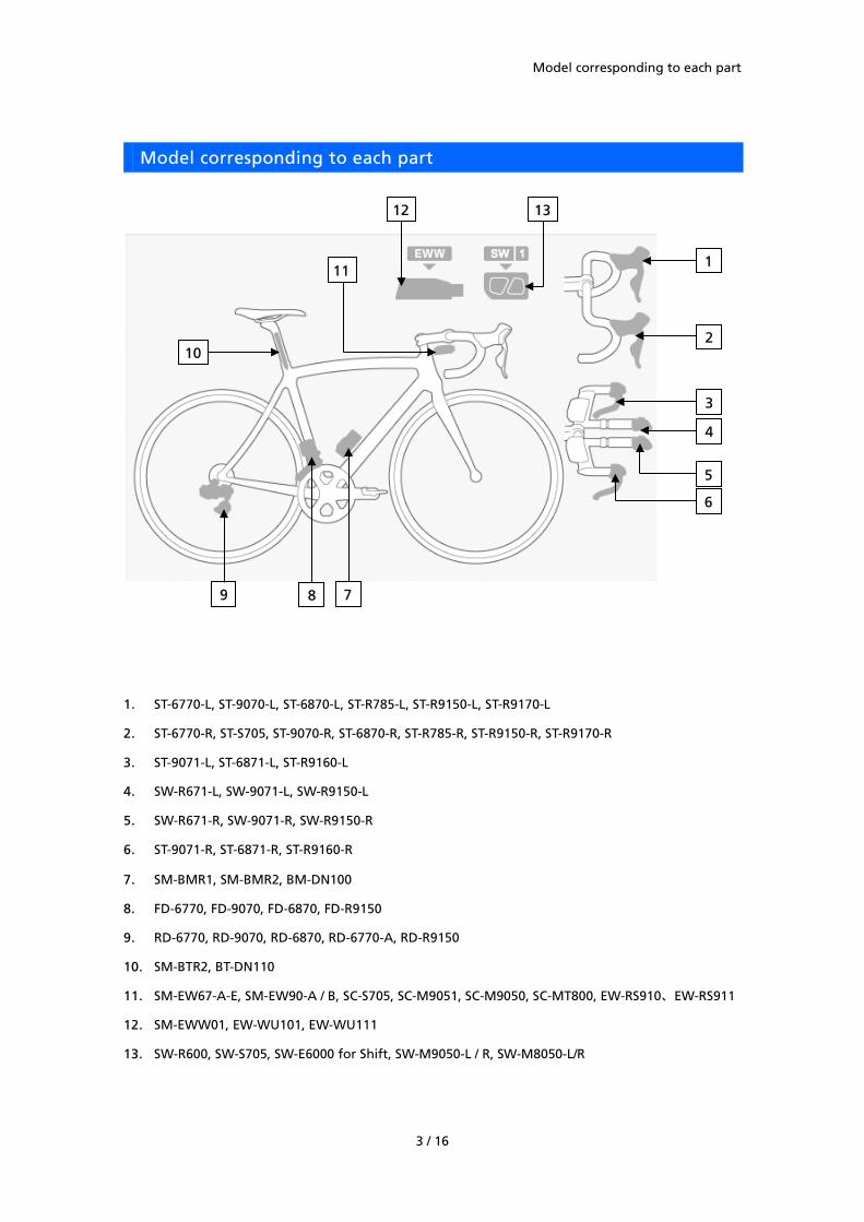
Model corresponding to each part ............................................................................................................. 3
13. SW-R600, SW-S705, SW-E6000 for Shift, SW-M9050-L / R, SW-M8050-L/R
1
7 8 9
10 2
6
3
4
5
13
11
12
CUSTOMIZE
4 / 16
CUSTOMIZE
This function is used to customize the gear shifting system.
1. Click [Customize] in the main screen.
(Main menu screen)
2. Click [Display monitor settings]* or [Switch setting] or [Front derailleur adjustment setting] or
[Rear derailleur adjustment setting] or [Multi shift mode setting] in the Customize menu screen
to move to the respective setting screens.
* When using SC-M9051, SC-M9050 or SC-MT800, [Display monitor settings] becomes available.
For details on [Display monitor settings], please read the E-TUBE PROJECT Application
Instruction Manual (MTB Edition).
(Customize menu screen)
CUSTOMIZE
5 / 16
Switch setting
Switch the shift switch function of the switch unit.
1. Display the customize menu screen.
2. Click [Switch setting] in the customize menu screen.
3. Select the desired setting for each switch.
The items that can be set are as follows.
Item Description
[Front Shift Up] Shifts the front derailleur from a smaller chainring to a larger chainring.
[Front Shift Down] Shifts the front derailleur from a larger chainring to a smaller chainring.
[Rear Shift Up] Shifts the rear derailleur from a larger sprocket to a smaller sprocket.
[Rear Shift Down] Shifts the rear derailleur from a smaller sprocket to a larger sprocket.
* Click [Restore default values] and then [Set] to restore the shift switch functions to the
factory settings.
4. Click [Set] to complete set up.
CUSTOMIZE
6 / 16
Front derailleur adjustment setting
This lets you adjust the front derailleur.
1. Display the customize menu screen.
2. Click [Front derailleur adjustment setting] in the customize menu screen.
3. Click [Yes].
If you have not performed low/top adjustment yet, click [No], disconnect the unit from the
PC, and perform adjustment.
For information on how to perform low / top adjustment, refer to the dealer's manual.
When [Adjustment method] is clicked, a different window appears.
4. Set the front derailleur to the second speed and the rear derailleur to the first speed before
adjustment. Follow the instructions on the screen and then click [Set].
5. Click [Down] / [Up] to adjust.
When [Front derailleur adjustment method] is clicked, a detailed description of the
adjustment method will be displayed in a different screen.
The settings to be adjusted are as follows.
Item Description
[Adjustment
setting]
[Down] Moves the chain guide toward the inside (- display direction).
[Up] Moves the chain guide toward the outside (+ display direction).
Displays the current set value in [Setting Value].
* The front derailleur and the rear derailleur will not operate while this procedure is being carried out, even if you operate the shifting switches.
* FD-6770 cannot be adjusted. * Rotate the crank arms while carrying out operations which are related to adjustment and
gear shifting.
6. Click [Set] to complete adjustment.
CUSTOMIZE
7 / 16
Rear derailleur adjustment setting
This lets you adjust the rear derailleur.
1. Display the customize menu screen.
2. Click [Rear derailleur adjustment setting] in the customize menu screen.
3. Click [Down] / [Up] to adjust.
Click [Rear derailleur adjustment method] in the rear derailleur adjustment setting screen to
display a separate screen with details on the adjustment method.
The settings to be adjusted are as follows.
Item Description
[Adjustment
setting]
[Down] Moves the guide pulley toward the inside (- display direction).
[Up] Moves the guide pulley toward the outside (+ display direction).
Displays the current set value in [Setting Value].
[Rear derailleur
gear shifting]
[Down] Shifts the rear derailleur from a smaller sprocket to a larger sprocket (- display direction).
[Up] Shifts the rear derailleur from a larger sprocket to a smaller sprocket (+ display direction).
Displays the current number of sprockets in [Gear position].
* The front derailleur and the rear derailleur will not operate while this procedure is being carried out, even if you operate the shifting switches.
* Rotate the crank arms while carrying out operations which are related to adjustment and gear shifting.
* The adjustment bolt judgment screen may be displayed while rear derailleur gear shifting operations are being carried out. If this happens, follow the instructions in the screen to adjust the adjustment bolt.
4. Click [Set] to complete adjustment.
CUSTOMIZE
8 / 16
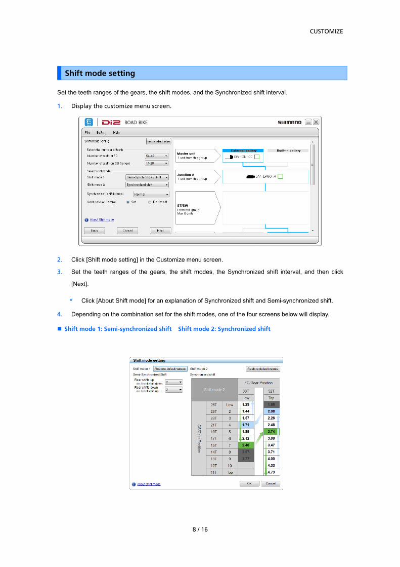
Shift mode setting
Set the teeth ranges of the gears, the shift modes, and the Synchronized shift interval.
1. Display the customize menu screen.
2. Click [Shift mode setting] in the Customize menu screen.
3. Set the teeth ranges of the gears, the shift modes, the Synchronized shift interval, and then click
[Next].
* Click [About Shift mode] for an explanation of Synchronized shift and Semi-synchronized shift.
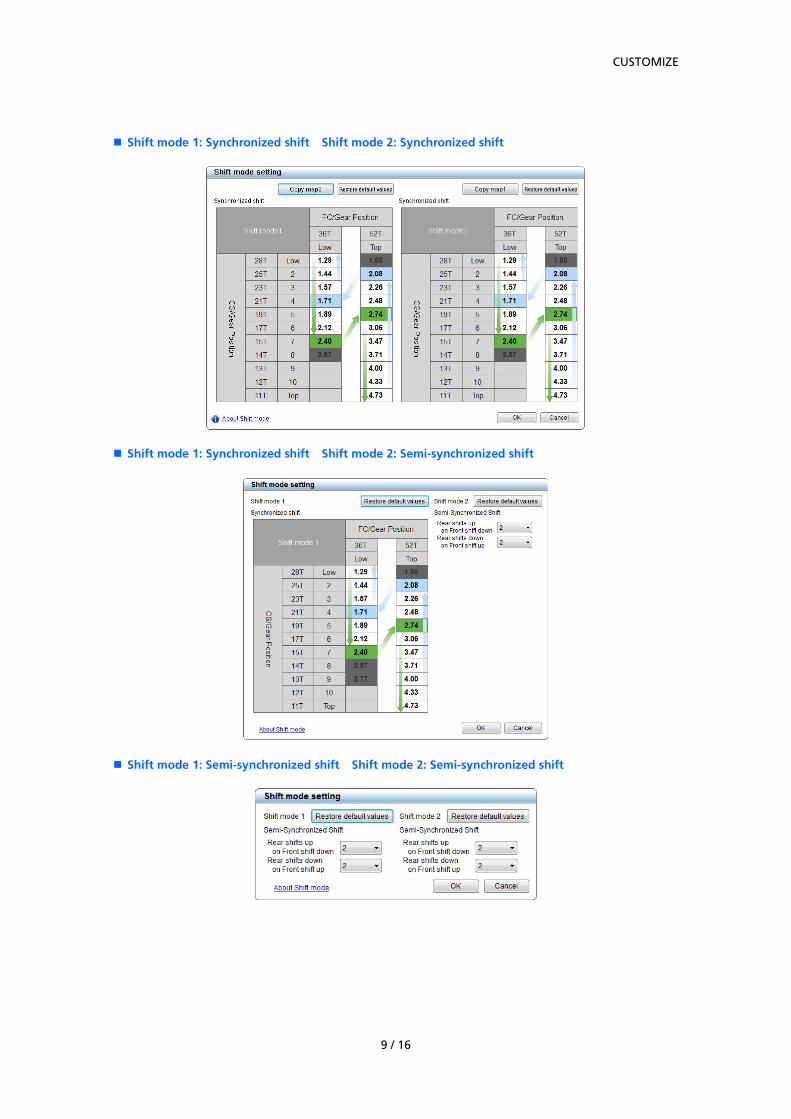
4. Depending on the combination set for the shift modes, one of the four screens below will display.
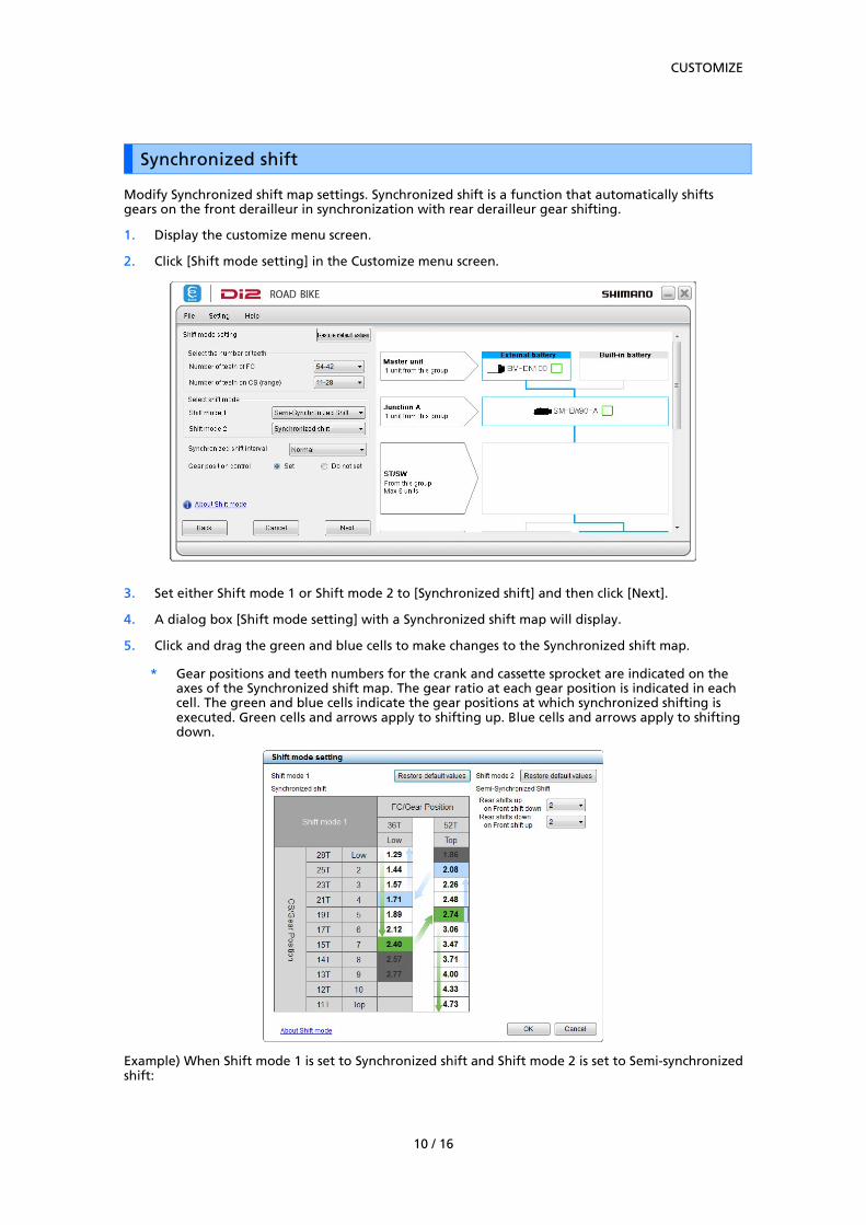
Modify Synchronized shift map settings. Synchronized shift is a function that automatically shifts gears on the front derailleur in synchronization with rear derailleur gear shifting.
1. Display the customize menu screen.
2. Click [Shift mode setting] in the Customize menu screen.
3. Set either Shift mode 1 or Shift mode 2 to [Synchronized shift] and then click [Next].
4. A dialog box [Shift mode setting] with a Synchronized shift map will display.
5. Click and drag the green and blue cells to make changes to the Synchronized shift map.
* Gear positions and teeth numbers for the crank and cassette sprocket are indicated on the axes of the Synchronized shift map. The gear ratio at each gear position is indicated in each cell. The green and blue cells indicate the gear positions at which synchronized shifting is executed. Green cells and arrows apply to shifting up. Blue cells and arrows apply to shifting down.
Example) When Shift mode 1 is set to Synchronized shift and Shift mode 2 is set to Semi-synchronized shift:
CUSTOMIZE
11 / 16
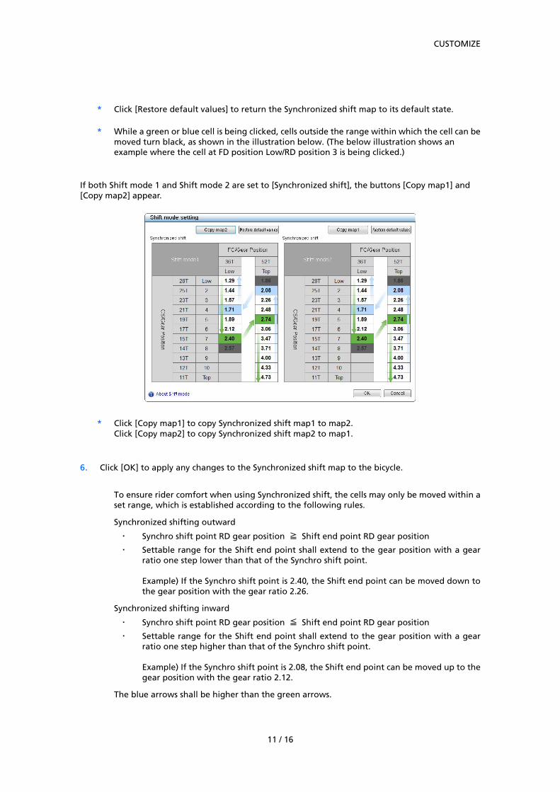
* Click [Restore default values] to return the Synchronized shift map to its default state.
* While a green or blue cell is being clicked, cells outside the range within which the cell can be moved turn black, as shown in the illustration below. (The below illustration shows an example where the cell at FD position Low/RD position 3 is being clicked.)
If both Shift mode 1 and Shift mode 2 are set to [Synchronized shift], the buttons [Copy map1] and [Copy map2] appear.
* Click [Copy map1] to copy Synchronized shift map1 to map2. Click [Copy map2] to copy Synchronized shift map2 to map1.
6. Click [OK] to apply any changes to the Synchronized shift map to the bicycle.
To ensure rider comfort when using Synchronized shift, the cells may only be moved within a set range, which is established according to the following rules.
Synchronized shifting outward
‧ Synchro shift point RD gear position ≧ Shift end point RD gear position
‧ Settable range for the Shift end point shall extend to the gear position with a gear ratio one step lower than that of the Synchro shift point. Example) If the Synchro shift point is 2.40, the Shift end point can be moved down to the gear position with the gear ratio 2.26.
Synchronized shifting inward
‧ Synchro shift point RD gear position ≦ Shift end point RD gear position
‧ Settable range for the Shift end point shall extend to the gear position with a gear ratio one step higher than that of the Synchro shift point. Example) If the Synchro shift point is 2.08, the Shift end point can be moved up to the gear position with the gear ratio 2.12.
The blue arrows shall be higher than the green arrows.
CUSTOMIZE
12 / 16
Example) The green cell (on right) is moved from FD position Top/RD position 3 to FD position Top/RD
position 4: Before, the green cell (on left) can be moved to RD position 7.
After, the green cell (on left) can be moved to RD position 8.
CUSTOMIZE
13 / 16
Semi-synchronized shift
Semi-synchronized shift is a function that automatically shifts the rear derailleur when the front derailleur is shifted in order to obtain optimal gear transition. It is possible to set the rear derailleur to jump from 1 to 4 gears. (Some gear numbers cannot be selected depending on gear combination.)
1. Display the customize menu screen.
2. Click [Shift mode setting] in the Customize menu screen.
3. Set either Shift mode 1 or Shift mode 2 to [Semi-synchronized shift] and then click [Next].
4. A dialog box [Shift mode setting] will display containing entry fields for Semi-synchronized shift.
Example) When Shift mode 1 and Shift mode 2 are both set to Semi-synchronized shift:
* Click [Restore default values] to return the values in the Rear shifts up on Front shift down and
Rear shifts down on Front shift up pull-down boxes to default values.
5. Click [OK] to apply any changes to Semi-synchronized shift values to the bicycle.
CUSTOMIZE
14 / 16
Multi shift mode setting
The multi shift mode setting can be changed.
Multi-shifting is a function to shift the rear derailleur by several gears in a row by holding down the
shift switch. (Multi-shifting cannot be used for the front derailleur.)
* To perform the multi shift mode setting, a battery unit or a battery mount unit needs to be
connected in addition to the derailleur.
1. Display the customize menu screen.
2. Click [Multi shift mode setting] in the customize menu screen.
3. Click each item to select the settings description.
The items that can be set are as follows.
Item Description
[Multi shift mode
setting]
Whether the multi shift mode is used or not can be selected. If you use a
2-step switch, you can select [ON] or [OFF] for each step. For other switches,
select [ON] or [OFF] in [Other Shifting Switch].
[Gear-shifting
interval]
The gear-shifting interval for multi shift can be selected from five levels.
[Gear number limit] A limitation can be placed on the number of gears that are shifted with one
long press.
4. Click [Set] to complete set up.
ERROR CHECK
15 / 16
ERROR CHECK
When a single unit or multiple units are connected, this function checks their operation and identifies
any units which have a problem.
1. Click [Error check] in the main menu screen.
2. Select the unit you want to check and then click [Start diagnosis].
An error check of the selected unit will start. Perform operations following the instructions
on the screen.
ABOUT THIS DOCUMENT
16 / 16
ABOUT THIS DOCUMENT
The contents of this document are subject to revision in the future without notice.
Reproducing or transmitting this document in whole or in part in any form or for any purpose
whatsoever without the express written permission of SHIMANO INC. is expressly forbidden. However,
this is not to be taken as a limit on the customer’s rights under applicable copyright laws.
SHIMANO INC. may own the rights to any patents, patent applications, trademarks, copyrights and
any other intangible property rights contained in this document. Unless otherwise specified, the
customer is not granted rights to any patents, trademarks, copyrights or any other intangible
intellectual property contained in this document.
REGISTERED TRADEMARKS AND TRADEMARKS
Shimano is a trademark or registered trademark of SHIMANO INC. in Japan and other countries.
is a trademark of SHIMANO, INC. in Japan and other countries.
Microsoft®, Windows Vista TM, Windows® 7, Windows® 8, Windows® 10 are registered trademarks or
trademarks of Microsoft Corporation in the United States of America and other countries.
All other company names, product names and service names, etc. are the property of their respective
owners.
Please note: specifications are subject to change for improvement without notice. (English)
One Holland, Irvine, California 92618, U.S.A. Phone: +1-949-951-5003
Industrieweg 24, 8071 CT Nunspeet, The Netherlands Phone: +31-341-272222
3-77 Oimatsu-cho, Sakai-ku, Sakai-shi, Osaka 590-8577, Japan


![Help Manual - Shimanoe-tubeproject.shimano.com/pdf/en/HM-EO.3.3.0-00-EN.pdf · * During this operation, ... [OFF] in [Other Shifting Switch]. [Gear-shifting interval] The gear-shifting](https://static.documents.pub/doc/80x56/5abdf0ba7f8b9a8e3f8c6455/help-manual-shimanoe-during-this-operation-off-in-other-shifting-switch.jpg)


![Help Manual - Shimanoe-tubeproject.shimano.com/pdf/en/HM-R.3.3.0-00-EN.pdfWhen D-FLY setting is possible (*), [Cyclecomputer left], [Cyclecomputer right], [Display], and [Display/Light]](https://static.documents.pub/doc/80x56/5ad33bcd7f8b9abd6c8dab2c/help-manual-shimanoe-d-fly-setting-is-possible-cyclecomputer-left-cyclecomputer.jpg)


