68
HERMETIC Hermetic Connectors High Performance Sealing Solutions
HE
RM
ET
IC
Hermetic ConnectorsHigh Performance Sealing Solutions

3
Hermetic Connectors
Presentation
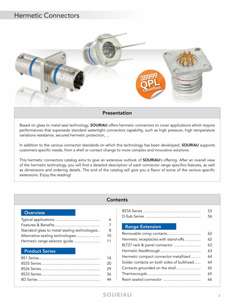
Based on glass to metal seal technology, SOURIAU offers hermetic connectors to cover applications which require performances that supersede standard watertight connectors capability, such as high pressure, high temperature variations resistance, secured hermetic protection, ...
In addition to the various connector standards on which this technology has been developed, SOURIAU supports customers specifi c needs, from a shell or contact change to more complex and innovative solutions.
This hermetic connectors catalog aims to give an extensive outlook of SOURIAU’s offering. After an overall view of the hermetic technology, you will fi nd a detailed description of each connector range specifi cs features, as well as dimensions and ordering details. The end of the catalog will give you a fl avor of some of the various specifi c extensions. Enjoy the reading!
Contents
Typical applications .......................................... 6Features & Benefi ts .......................................... 7Standard glass to metal sealing technologies .. 8Alternative sealing technologies ...................... 10Hermetic range selector guide ........................ 11
Overview
851 Series ......................................................... 148525 Series ....................................................... 208526 Series ....................................................... 298533 Series ....................................................... 368D Series .......................................................... 44
Product Series
Removable crimp contacts ............................... 62Hermetic receptacles with stand-offs ............... 628LT27 rack & panel connector ......................... 63Hermetic feedthrough ...................................... 63Hermetic compact connector metallized ......... 64 Solder contacts on both sides of bulkhead ...... 64Contacts grounded on the shell ....................... 65Thermocouple .................................................. 65Resin sealed connector ................................... 66
Range Extension
8STA Series ...................................................... 53D-Sub Series .................................................... 56
38999QPL Qualifi ed
HE
RM
ET
IC
© 2017 SOURIAU - SOURIAU is a registered trademark
OverviewHermetic
Typical applications ................................................................................................ 6
Features & Benefi ts ............................................................................................... 7
Standard glass to metal sealing technologies ........................................................ 8
Alternative sealing technologies ............................................................................ 10
Hermetic range selector guide ............................................................................... 11
6
Hermetic Connectors | Overview
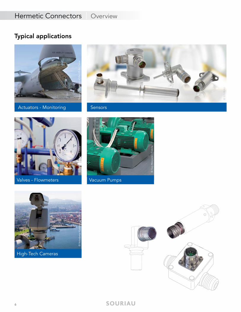
Typical applications
Valves - Flowmeters
High-Tech Cameras
Vacuum Pumps
Sensors
© S
OU
RIA
U
Actuators - Monitoring
© Y
ury
Mar
yuni
n /
Foto
lia
© T
rofo
tod
esig
n /
Foto
lia
© V
olod
ymyr
Kyr
ylyu
k /
Foto
liaN
atio
nal M
useu
m o
f the
US
Air
Forc
e
7
Hermetic Connectors | Overview
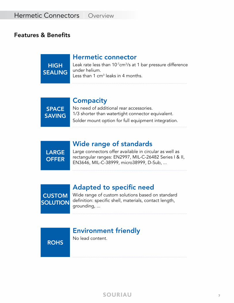
Features & Benefi ts
HIGH SEALING
SPACE SAVING
LARGE OFFER
CUSTOMSOLUTION
ROHS
Hermetic connector Leak rate less than 10-7cm3/s at 1 bar pressure difference under helium.Less than 1 cm3 leaks in 4 months.
Adapted to specifi c needWide range of custom solutions based on standard defi nition: specifi c shell, materials, contact length, grounding, ...
Environment friendlyNo lead content.
Wide range of standards Large connectors offer available in circular as well as rectangular ranges: EN2997, MIL-C-26482 Series I & II, EN3646, MIL-C-38999, micro38999, D-Sub, ...
Compacity No need of additional rear accessories.1/3 shorter than watertight connector equivalent.Solder mount option for full equipment integration.
8
Hermetic Connectors | Overview
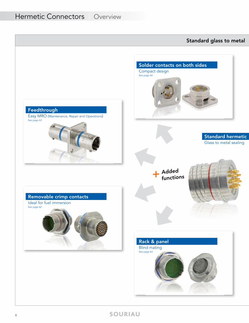
Standard glass to metal
Standard hermeticGlass to metal sealing
+ Added
functions
Solder contacts on both sidesCompact designSee page 64
Rack & panelBlind matingSee page 63
FeedthroughEasy MRO (Maintenance, Repair and Operations)See page 63
Removable crimp contactsIdeal for fuel immersionSee page 62
9
Hermetic Connectors | Overview
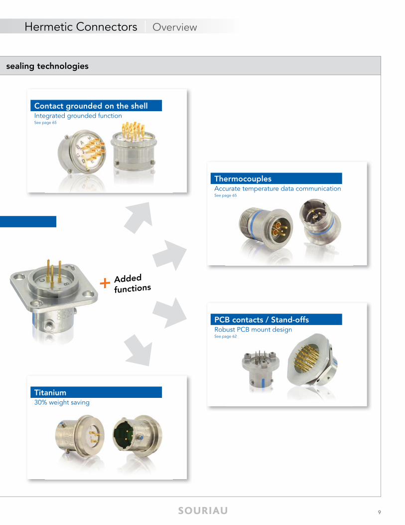
sealing technologies
+ Added
functions
Contact grounded on the shellIntegrated grounded functionSee page 65
Titanium30% weight saving
PCB contacts / Stand-offsRobust PCB mount designSee page 62
ThermocouplesAccurate temperature data communicationSee page 65
10
Standard glass to metal sealing technologies
Hermetic Connectors | Overview
Alternative sealing technologies
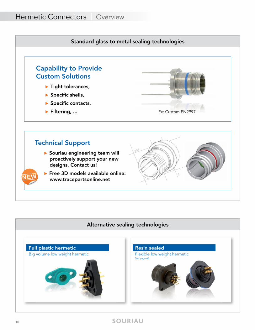
Capability to Provide Custom Solutions
► Tight tolerances,
► Specifi c shells,
► Specifi c contacts,
► Filtering, ... Ex: Custom EN2997
Technical Support► Souriau engineering team will proactively support your new designs. Contact us!
► Free 3D models available online: www.tracepartsonline.netNEW
Full plastic hermeticBig volume low weight hermetic
Resin sealedFlexible low weight hermeticSee page 66
11
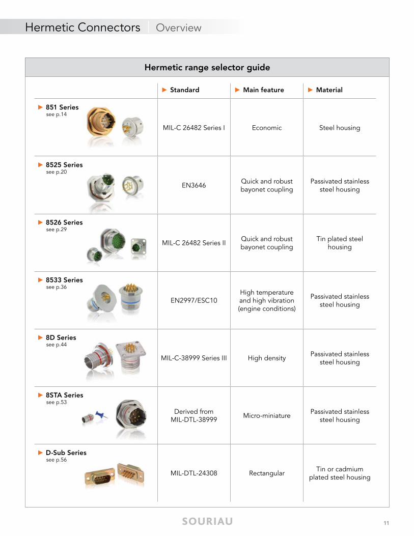
► Standard ► Main feature ► Material
► 851 Series see p.14
MIL-C 26482 Series I Economic Steel housing
► 8525 Series see p.20
EN3646 Quick and robust bayonet coupling
Passivated stainless steel housing
► 8526 Series see p.29
MIL-C 26482 Series II Quick and robust bayonet coupling
Tin plated steelhousing
► 8533 Series see p.36
EN2997/ESC10High temperatureand high vibration (engine conditions)
Passivated stainless steel housing
► 8D Series see p.44
MIL-C-38999 Series III High density Passivated stainless steel housing
► 8STA Series see p.53
Derived fromMIL-DTL-38999 Micro-miniature Passivated stainless
steel housing
► D-Sub Series see p.56
MIL-DTL-24308 Rectangular Tin or cadmiumplated steel housing
Hermetic Connectors | Overview
Hermetic range selector guide

HE
RM
ET
IC
© 2017 SOURIAU - SOURIAU is a registered trademark
Product SeriesHermetic
851 Series ............................................................................................................... 14
8525 Series ............................................................................................................. 20
8526 Series ............................................................................................................. 29
8533 Series ............................................................................................................. 36
8D Series ............................................................................................................... 44
8STA Series ............................................................................................................. 53
D-Sub Series ........................................................................................................... 56
14
Hermetic Connectors | 851 Series
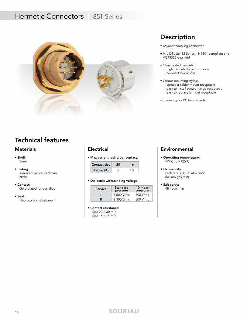
Description• Bayonet coupling connector
• MIL-DTL-26482 Series I, HE301 compliant and VG95328 qualifi ed
• Glass sealed hermetic: . high hermeticity performance . compact low profi le
• Various mounting styles: . compact solder mount receptacle . easy to install square fl ange receptacle . easy to replace jam nut receptacle
• Solder cup or PC tail contacts
Technical featuresMaterials
• Shell: Steel
• Plating: Iridescent yellow cadmium Nickel
• Contact: Gold plated ferrous alloy
• Seal: Fluorocarbon elastomer
Electrical
• Max current rating per contact:
• Dielectric withstanding voltage:
• Contact resistance: Size 20 ≤ 30 mΩ Size 16 ≤ 14 mΩ
Environmental
• Operating temperature: -55°C to +125°C
• Hermeticity: Leak rate < 1.10-7 atm.cm3/s (helium gas test)
• Salt spray: 48 hours min
Contact size 20 16
Rating (A) 5 10
Service Standard pressure
10 mbar pressure
I 1 500 Vrms 200 VrmsII 2 300 Vrms 300 Vrms
15
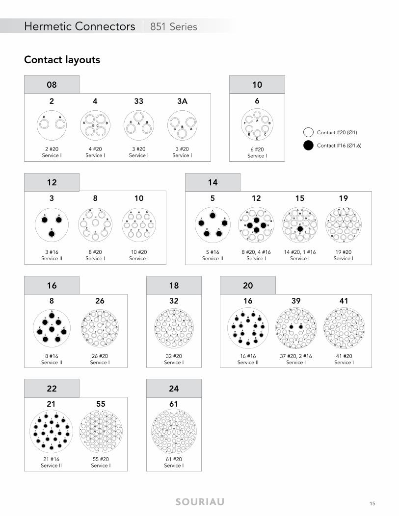
Contact layouts
3
3 #16Service II
8
8 #20Service I
10
10 #20Service I
26
26 #20Service I
8
8 #16Service II
Contact #20 (Ø1)
Contact #16 (Ø1.6)
2
2 #20Service I
08
6
6 #20Service I
10
12
16
32
32 #20Service I
18
21
21 #16Service II
22
61
61 #20Service I
24
Hermetic Connectors | 851 Series
3A
3 #20Service I
4
4 #20Service I
33
3 #20Service I
5
5 #16Service II
15
14 #20, 1 #16Service I
12
8 #20, 4 #16Service I
14
19
19 #20Service I
16
16 #16Service II
20
39
37 #20, 2 #16Service I
41
41 #20Service I
55
55 #20Service I
16
Hermetic Connectors | 851 Series
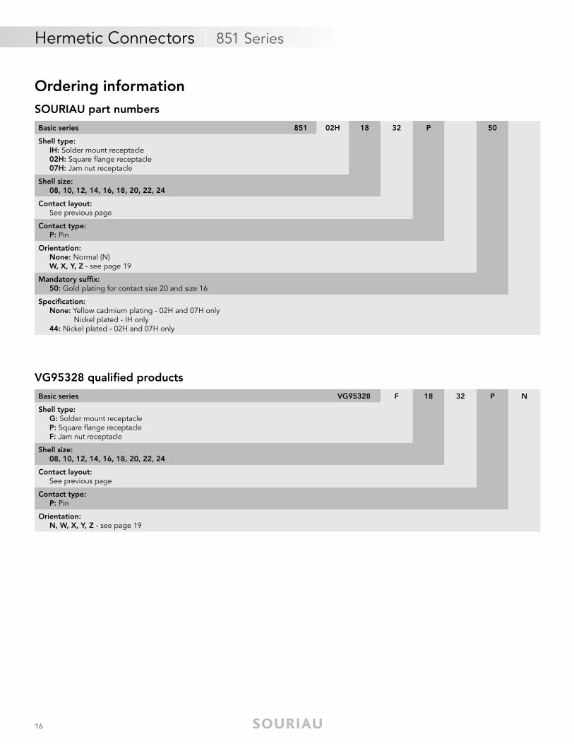
Ordering information
Basic series 851 02H 18 32 P 50
Shell type: IH: Solder mount receptacle 02H: Square fl ange receptacle 07H: Jam nut receptacle
Shell size: 08, 10, 12, 14, 16, 18, 20, 22, 24
Contact layout: See previous page
Contact type: P: Pin
Orientation: None: Normal (N) W, X, Y, Z - see page 19
Mandatory suffi x: 50: Gold plating for contact size 20 and size 16
Specifi cation: None: Yellow cadmium plating - 02H and 07H only Nickel plated - IH only 44: Nickel plated - 02H and 07H only
VG95328 qualifi ed products
Basic series VG95328 F 18 32 P N
Shell type: G: Solder mount receptacle P: Square fl ange receptacle F: Jam nut receptacle
Shell size: 08, 10, 12, 14, 16, 18, 20, 22, 24
Contact layout: See previous page
Contact type: P: Pin
Orientation: N, W, X, Y, Z - see page 19
SOURIAU part numbers
17
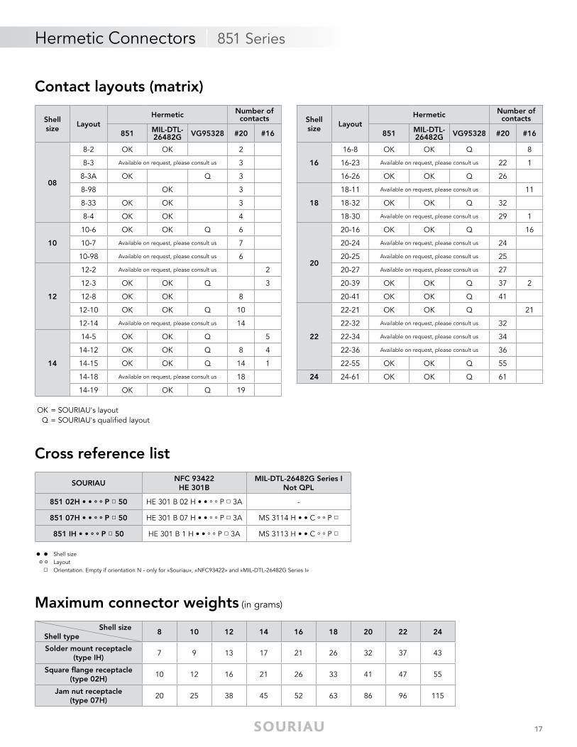
Cross reference list
Maximum connector weights (in grams)
• • Shell size
° ° Layout □ Orientation. Empty if orientation N - only for «Souriau», «NFC93422» and «MIL-DTL-26482G Series I»
SOURIAUNFC 93422
HE 301BMIL-DTL-26482G Series I
Not QPL
851 02H • • ° ° P □ 50 HE 301 B 02 H • • ° ° P □ 3A -
851 07H • • ° ° P □ 50 HE 301 B 07 H • • ° ° P □ 3A MS 3114 H • • C ° ° P □
851 IH • • ° ° P □ 50 HE 301 B 1 H • • ° ° P □ 3A MS 3113 H • • C ° ° P □
Shell size Shell type
8 10 12 14 16 18 20 22 24
Solder mount receptacle(type IH)
7 9 13 17 21 26 32 37 43
Square fl ange receptacle(type 02H)
10 12 16 21 26 33 41 47 55
Jam nut receptacle(type 07H)
20 25 38 45 52 63 86 96 115
Contact layouts (matrix)
Shell size
LayoutHermetic Number of
contacts
851 MIL-DTL-26482G VG95328 #20 #16
08
8-2 OK OK 2
8-3 Available on request, please consult us 3
8-3A OK Q 3
8-98 OK 3
8-33 OK OK 3
8-4 OK OK 4
10
10-6 OK OK Q 6
10-7 Available on request, please consult us 7
10-98 Available on request, please consult us 6
12
12-2 Available on request, please consult us 2
12-3 OK OK Q 3
12-8 OK OK 8
12-10 OK OK Q 10
12-14 Available on request, please consult us 14
14
14-5 OK OK Q 5
14-12 OK OK Q 8 4
14-15 OK OK Q 14 1
14-18 Available on request, please consult us 18
14-19 OK OK Q 19
Hermetic Connectors | 851 Series
OK = SOURIAU's layoutQ = SOURIAU's qualifi ed layout
Shell size
LayoutHermetic Number of
contacts
851 MIL-DTL-26482G VG95328 #20 #16
16
16-8 OK OK Q 8
16-23 Available on request, please consult us 22 1
16-26 OK OK Q 26
18
18-11 Available on request, please consult us 11
18-32 OK OK Q 32
18-30 Available on request, please consult us 29 1
20
20-16 OK OK Q 16
20-24 Available on request, please consult us 24
20-25 Available on request, please consult us 25
20-27 Available on request, please consult us 27
20-39 OK OK Q 37 2
20-41 OK OK Q 41
22
22-21 OK OK Q 21
22-32 Available on request, please consult us 32
22-34 Available on request, please consult us 34
22-36 Available on request, please consult us 36
22-55 OK OK Q 55
24 24-61 OK OK Q 61
18
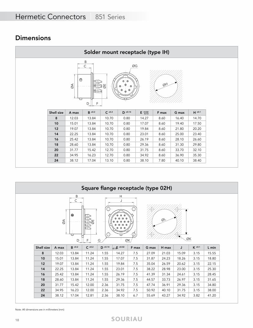
Note: All dimensions are in millimeters (mm)
Solder mount receptacle (type IH)
Square fl ange receptacle (type 02H)
Hermetic Connectors | 851 Series
Dimensions
ØA
D
ØGBC
F
ØH
ØE
Shell size A max B ±0.2 C ±0.2 D ±0.14 E +0.02 F max G max H ±0.1
8 12.03 13.84 10.70 0.80 14.27 8.60 16.40 14.70
10 15.01 13.84 10.70 0.80 17.07 8.60 19.40 17.50
12 19.07 13.84 10.70 0.80 19.84 8.60 21.80 20.20
14 22.25 13.84 10.70 0.80 23.01 8.60 25.00 23.40
16 25.42 13.84 10.70 0.80 26.19 8.60 28.10 26.60
18 28.60 13.84 10.70 0.80 29.36 8.60 31.30 29.80
20 31.77 15.42 12.70 0.80 31.75 8.60 33.70 32.10
22 34.95 16.23 12.70 0.80 34.92 8.60 36.90 35.30
24 38.12 17.04 13.10 0.80 38.10 7.80 40.10 38.40
-0.13
ØA
D
BC
F ØK
ØE
G
JH
ØL
ØK
Shell size A max B ±0.2 C ±0.2 D ±0.14 E ±0.02 F max G max H max J K ±0.1 L min
8 12.03 13.84 11.24 1.55 14.27 7.5 27.09 21.03 15.09 3.15 15.55
10 15.01 13.84 11.24 1.55 17.07 7.5 31.87 24.23 18.26 3.15 18.80
12 19.07 13.84 11.24 1.55 19.84 7.5 35.04 26.59 20.62 3.15 22.15
14 22.25 13.84 11.24 1.55 23.01 7.5 38.22 28.98 23.00 3.15 25.30
16 25.42 13.84 11.24 1.55 26.19 7.5 41.39 31.34 24.61 3.15 28.45
18 28.60 13.84 11.24 1.55 29.36 7.5 44.57 33.73 26.97 3.15 31.65
20 31.77 15.42 12.00 2.36 31.75 7.5 47.74 36.91 29.36 3.15 34.80
22 34.95 16.23 12.00 2.36 34.92 7.5 50.92 40.10 31.75 3.15 38.00
24 38.12 17.04 12.81 2.36 38.10 6.7 55.69 43.27 34.92 3.82 41.20
-0.13
19
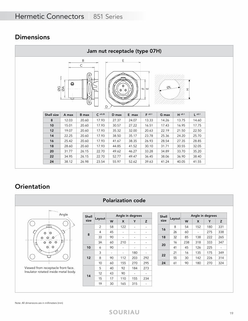
Hermetic Connectors | 851 Series
Note: All dimensions are in millimeters (mm)
Orientation
Shell size A max B max C ±0.25 D max E max F ±0.1 G max H ±0.1 L ±0.1
8 12.03 20.60 17.93 27.37 24.07 13.33 14.26 13.75 14.60
10 15.01 20.60 17.93 30.57 27.22 16.51 17.43 16.95 17.75
12 19.07 20.60 17.93 35.32 32.00 20.63 22.19 21.50 22.50
14 22.25 20.60 17.93 38.50 35.17 23.78 25.36 24.20 25.70
16 25.42 20.60 17.93 41.67 38.35 26.93 28.54 27.35 28.85
18 28.60 20.60 17.93 44.85 41.52 30.10 31.71 30.55 32.05
20 31.77 26.15 22.70 49.62 46.27 33.28 34.89 33.70 35.20
22 34.95 26.15 22.70 52.77 49.47 36.45 38.06 36.90 38.40
24 38.12 26.98 23.54 55.97 52.62 39.63 41.24 40.05 41.55
Shell size
LayoutAngle in degrees
W X Y Z
8
2 58 122 - -
4 45 - - -
33 90 - - -
3A 60 210 - -
10 6 90 - - -
12
3 - - 180 -
8 90 112 203 292
10 60 155 270 295
14
5 40 92 184 273
12 43 90 - -
15 17 110 155 234
19 30 165 315 -
Shell size
LayoutAngle in degrees
W X Y Z
168 54 152 180 331
26 60 - 275 338
18 32 85 138 222 265
2016 238 318 333 347
41 45 126 225 -
2221 16 135 175 349
55 30 142 226 314
24 61 90 180 270 324
Jam nut receptacle (type 07H)
Polarization code
Viewed from receptacle front face.Insulator rotated inside metal body.
Angle
ØA
ØG
B
C
F E
D
E
HØL
Dimensions
20
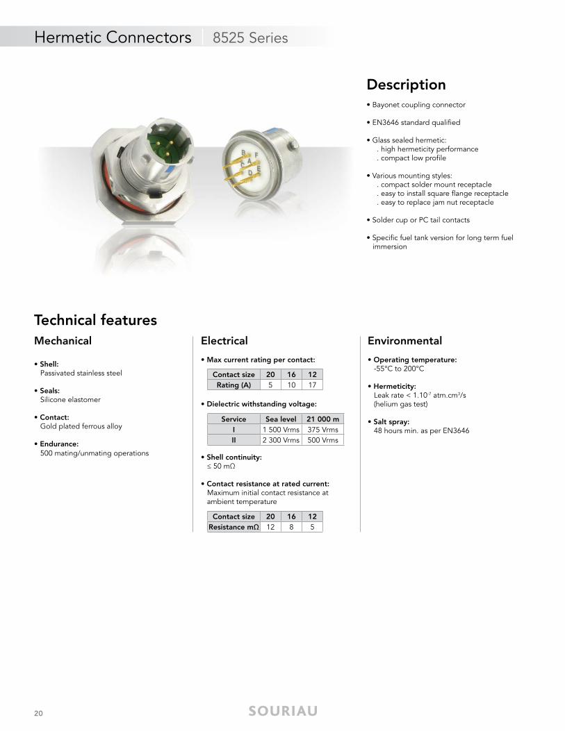
Mechanical
• Shell: Passivated stainless steel
• Seals: Silicone elastomer
• Contact: Gold plated ferrous alloy
• Endurance: 500 mating/unmating operations
Electrical
• Max current rating per contact:
• Dielectric withstanding voltage:
• Shell continuity: ≤ 50 mΩ
• Contact resistance at rated current: Maximum initial contact resistance at ambient temperature
Environmental
• Operating temperature: -55°C to 200°C
• Hermeticity: Leak rate < 1.10-7 atm.cm3/s (helium gas test)
• Salt spray: 48 hours min. as per EN3646
Hermetic Connectors | 8525 Series
Description• Bayonet coupling connector
• EN3646 standard qualifi ed
• Glass sealed hermetic: . high hermeticity performance . compact low profi le
• Various mounting styles: . compact solder mount receptacle . easy to install square fl ange receptacle . easy to replace jam nut receptacle
• Solder cup or PC tail contacts
• Specifi c fuel tank version for long term fuel immersion
Technical features
Service Sea level 21 000 mI 1 500 Vrms 375 VrmsII 2 300 Vrms 500 Vrms
Contact size 20 16 12Rating (A) 5 10 17
Contact size 20 16 12Resistance mΩ 12 8 5
21
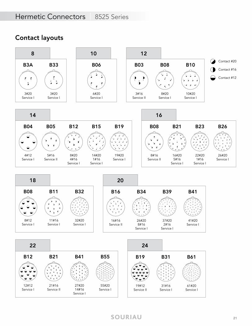
Hermetic Connectors | 8525 Series
Contact layouts
B3A
3#20Service I
B33
3#20Service I
8
B04
4#12 Service I
B05
5#16 Service II
B12
8#204#16
Service I
B15
14#201#16
Service I
B19
19#20 Service I
14 16
B08
8#16 Service II
B21
16#205#16
Service I
B26
26#20 Service I
B23
22#20 1#16
Service I
18
B08
8#12 Service I
B11
11#16 Service I
B32
32#20 Service I
20
B16
16#16 Service II
B39
37#202#16
Service I
B41
41#20 Service I
B34
26#208#16
Service I
B06
6#20Service I
10 12
B03
3#16Service II
B10
10#20Service I
B08
8#20Service I
24
B19
19#12 Service II
B31
31#16 Service I
B61
61#20 Service I
22
B12
12#12 Service I
B21
21#16 Service II
B41 B55
27#2014#16
Service I
55#20 Service I
Contact #20
Contact #16
Contact #12
22
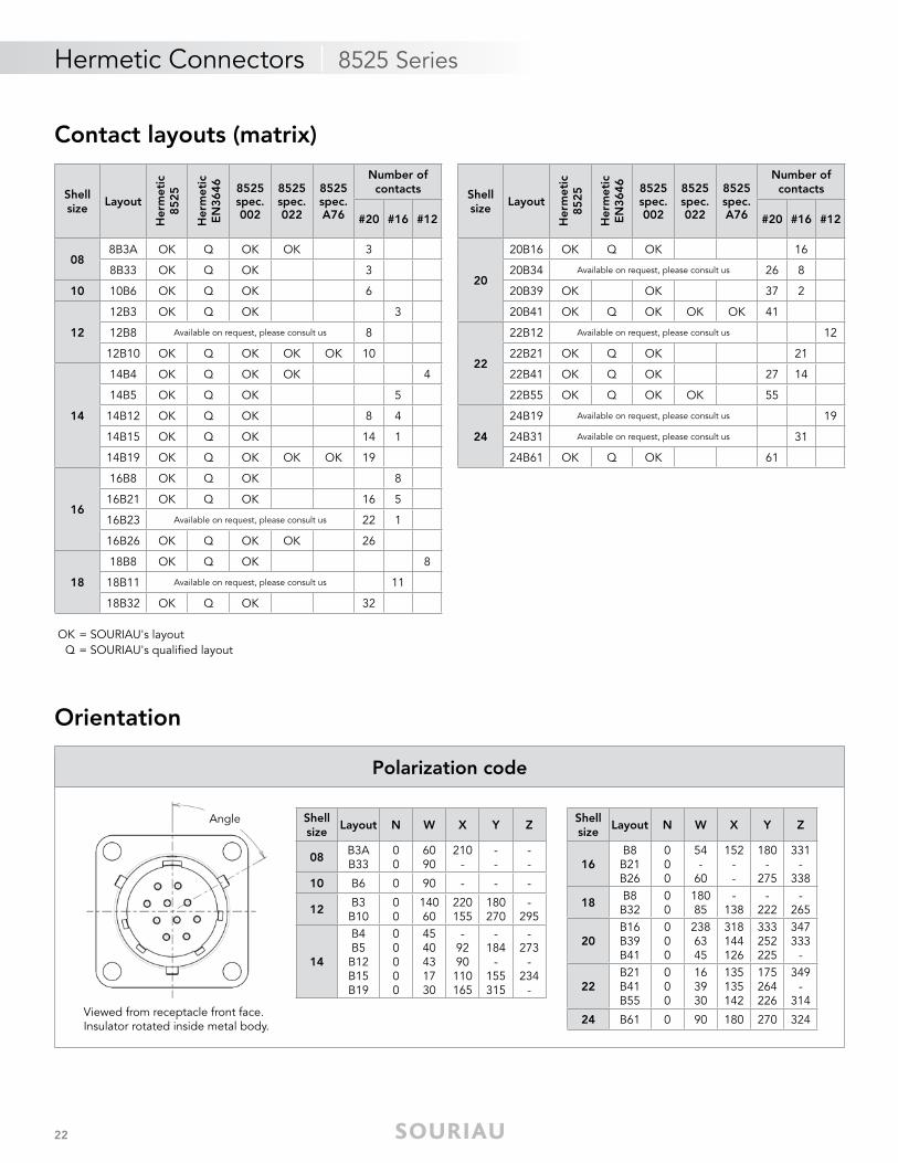
Hermetic Connectors | 8525 Series
Contact layouts (matrix)
OK = SOURIAU's layoutQ = SOURIAU's qualifi ed layout
Orientation
Shellsize
Layout
Her
met
ic85
25
Her
met
icE
N36
46 8525spec. 002
8525spec. 022
8525spec. A76
Number of contacts
#20 #16 #12
088B3A OK Q OK OK 3
8B33 OK Q OK 3
10 10B6 OK Q OK 6
12
12B3 OK Q OK 3
12B8 Available on request, please consult us 8
12B10 OK Q OK OK OK 10
14
14B4 OK Q OK OK 4
14B5 OK Q OK 5
14B12 OK Q OK 8 4
14B15 OK Q OK 14 1
14B19 OK Q OK OK OK 19
16
16B8 OK Q OK 8
16B21 OK Q OK 16 5
16B23 Available on request, please consult us 22 1
16B26 OK Q OK OK 26
18
18B8 OK Q OK 8
18B11 Available on request, please consult us 11
18B32 OK Q OK 32
Shell size
Layout N W X Y Z
08B3AB33
00
6090
210-
--
--
10 B6 0 90 - - -
12B3B10
00
14060
220155
180270
-295
14
B4B5B12B15B19
00000
4540431730
-9290110165
-184
-155315
-273
-234
-
Shell size
Layout N W X Y Z
16B8B21B26
000
54-
60
152--
180-
275
331-
338
18B8B32
00
18085
-138
-222
-265
20B16B39B41
000
2386345
318144126
333252225
347333
-
22B21B41B55
000
163930
135135142
175264226
349-
314
24 B61 0 90 180 270 324
Polarization code
Viewed from receptacle front face.Insulator rotated inside metal body.
Angle
Shellsize
Layout
Her
met
ic85
25
Her
met
icE
N36
46 8525spec. 002
8525spec. 022
8525spec. A76
Number of contacts
#20 #16 #12
20
20B16 OK Q OK 16
20B34 Available on request, please consult us 26 8
20B39 OK OK 37 2
20B41 OK Q OK OK OK 41
22
22B12 Available on request, please consult us 12
22B21 OK Q OK 21
22B41 OK Q OK 27 14
22B55 OK Q OK OK 55
24
24B19 Available on request, please consult us 19
24B31 Available on request, please consult us 31
24B61 OK Q OK 61
23
Hermetic Connectors | 8525 Series
Ordering informationSOURIAU part numbers
EN3646 qualifi ed products
Maximum connector weights (in grams)
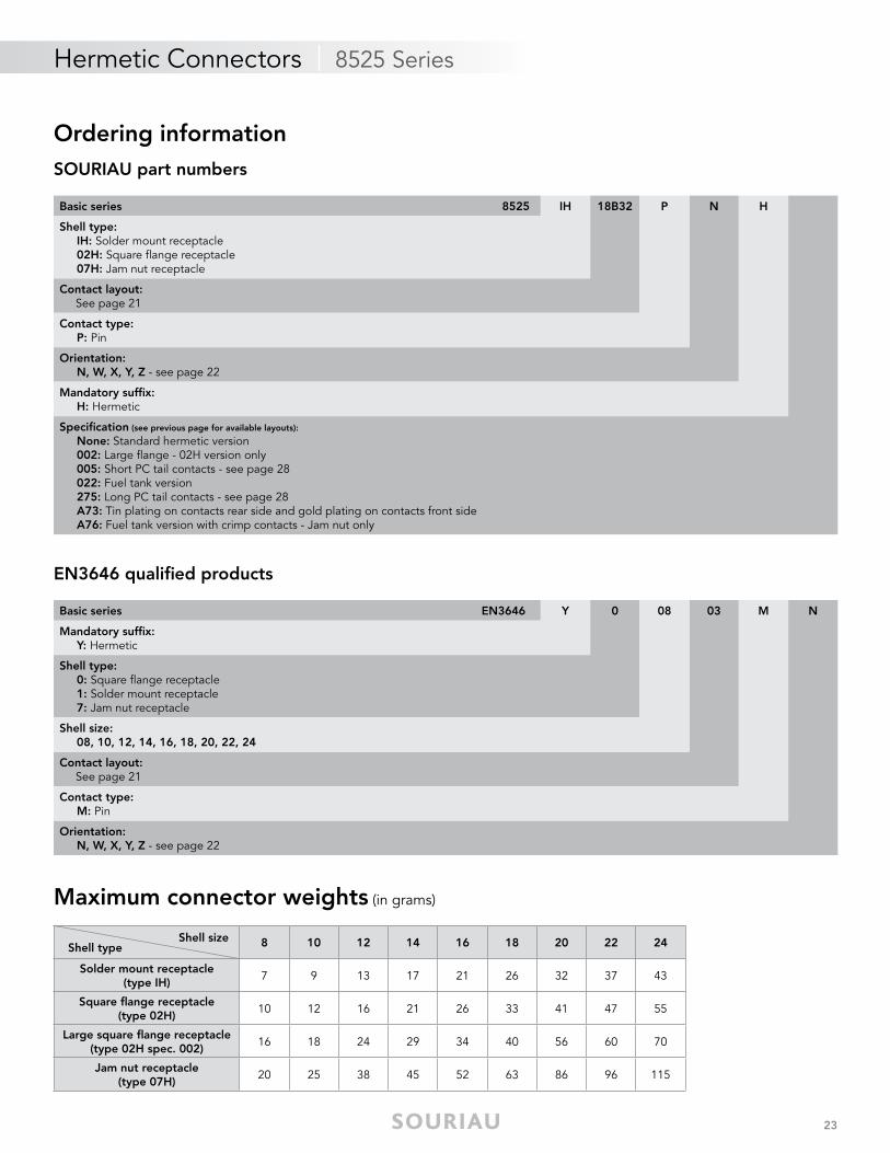
Basic series 8525 IH 18B32 P N H
Shell type: IH: Solder mount receptacle 02H: Square fl ange receptacle 07H: Jam nut receptacle
Contact layout: See page 21
Contact type: P: Pin
Orientation: N, W, X, Y, Z - see page 22
Mandatory suffi x: H: Hermetic
Specifi cation (see previous page for available layouts):
None: Standard hermetic version 002: Large fl ange - 02H version only 005: Short PC tail contacts - see page 28 022: Fuel tank version 275: Long PC tail contacts - see page 28 A73: Tin plating on contacts rear side and gold plating on contacts front side A76: Fuel tank version with crimp contacts - Jam nut only
Basic series EN3646 Y 0 08 03 M N
Mandatory suffi x: Y: Hermetic
Shell type: 0: Square fl ange receptacle 1: Solder mount receptacle 7: Jam nut receptacle
Shell size: 08, 10, 12, 14, 16, 18, 20, 22, 24
Contact layout: See page 21
Contact type: M: Pin
Orientation: N, W, X, Y, Z - see page 22
Shell size Shell type 8 10 12 14 16 18 20 22 24
Solder mount receptacle(type IH)
7 9 13 17 21 26 32 37 43
Square fl ange receptacle(type 02H)
10 12 16 21 26 33 41 47 55
Large square fl ange receptacle(type 02H spec. 002)
16 18 24 29 34 40 56 60 70
Jam nut receptacle(type 07H)
20 25 38 45 52 63 86 96 115
24
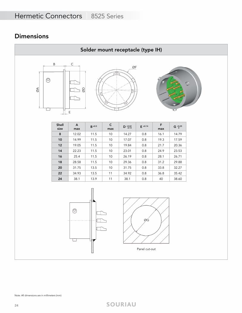
Hermetic Connectors | 8525 Series
DimensionsØ
A
ØD
ØFB C
E
ØG
Panel cut-out
Shellsize
Amax
B ±0.5 Cmax
D +0.02 E ±0.14 Fmax
G +0,25
8 12.02 11.5 10 14.27 0.8 16.1 14.79
10 14.99 11.5 10 17.07 0.8 19.3 17.59
12 19.05 11.5 10 19.84 0.8 21.7 20.36
14 22.23 11.5 10 23.01 0.8 24.9 23.53
16 25.4 11.5 10 26.19 0.8 28.1 26.71
18 28.58 11.5 10 29.36 0.8 31.2 29.88
20 31.75 13.5 10 31.75 0.8 33.8 32.27
22 34.93 13.5 11 34.92 0.8 36.8 35.42
24 38.1 13.9 11 38.1 0.8 40 38.60
0-0.13
Note: All dimensions are in millimeters (mm)
Solder mount receptacle (type IH)
25
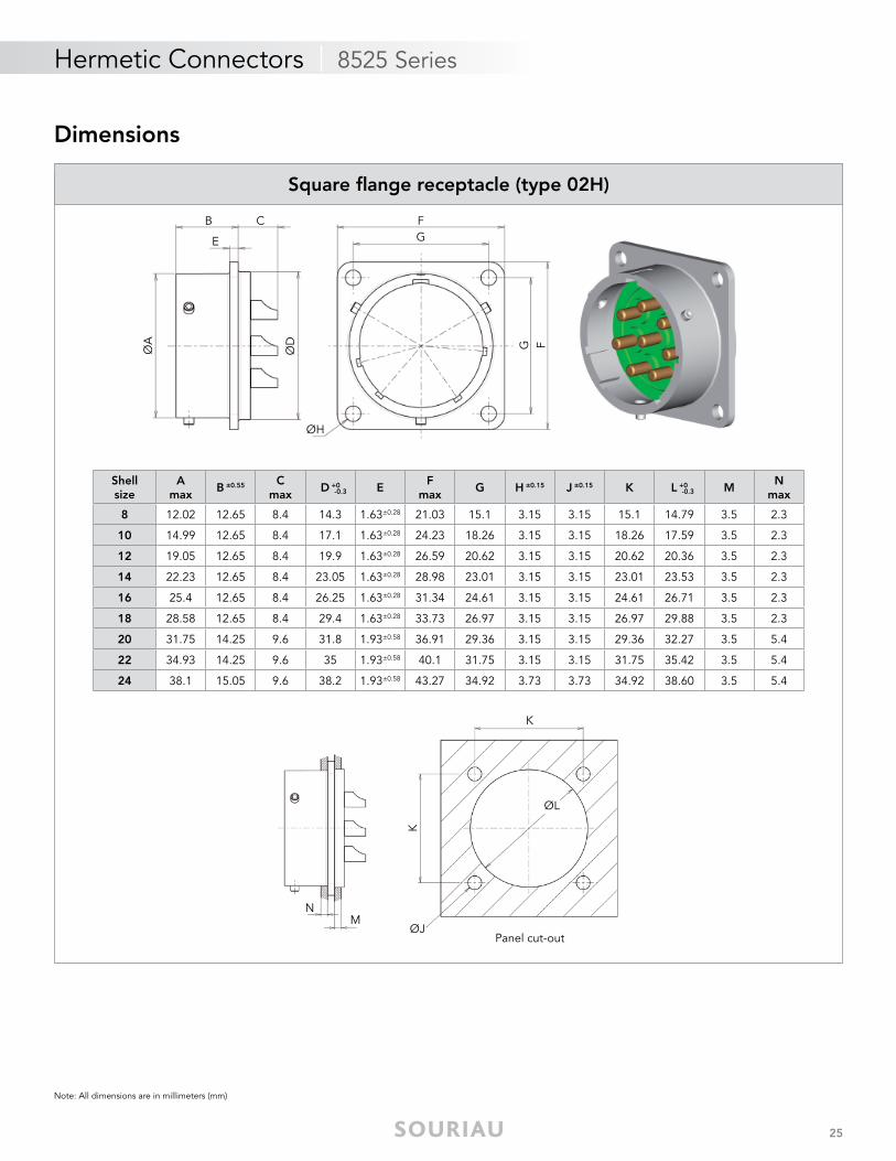
Hermetic Connectors | 8525 Series
Note: All dimensions are in millimeters (mm)
ØA
ØD
ØH
B C
E
FG
FG
ØJ
N
K
M
ØL
K
Panel cut-out
Shellsize
Amax
B ±0.55 Cmax
D +0 EF
maxG H ±0.15 J ±0.15 K L +0 M
Nmax
8 12.02 12.65 8.4 14.3 1.63±0.28 21.03 15.1 3.15 3.15 15.1 14.79 3.5 2.3
10 14.99 12.65 8.4 17.1 1.63±0.28 24.23 18.26 3.15 3.15 18.26 17.59 3.5 2.3
12 19.05 12.65 8.4 19.9 1.63±0.28 26.59 20.62 3.15 3.15 20.62 20.36 3.5 2.3
14 22.23 12.65 8.4 23.05 1.63±0.28 28.98 23.01 3.15 3.15 23.01 23.53 3.5 2.3
16 25.4 12.65 8.4 26.25 1.63±0.28 31.34 24.61 3.15 3.15 24.61 26.71 3.5 2.3
18 28.58 12.65 8.4 29.4 1.63±0.28 33.73 26.97 3.15 3.15 26.97 29.88 3.5 2.3
20 31.75 14.25 9.6 31.8 1.93±0.58 36.91 29.36 3.15 3.15 29.36 32.27 3.5 5.4
22 34.93 14.25 9.6 35 1.93±0.58 40.1 31.75 3.15 3.15 31.75 35.42 3.5 5.4
24 38.1 15.05 9.6 38.2 1.93±0.58 43.27 34.92 3.73 3.73 34.92 38.60 3.5 5.4
-0.3 -0.3
Square fl ange receptacle (type 02H)
Dimensions
26
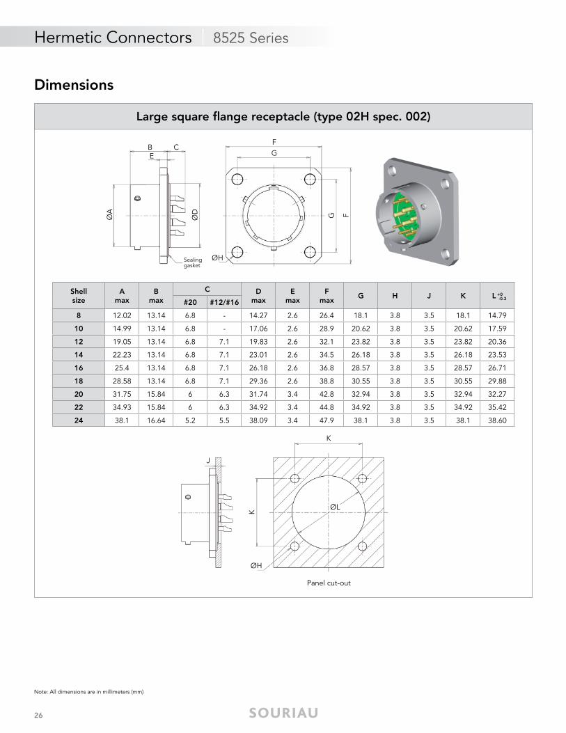
Hermetic Connectors | 8525 Series
Note: All dimensions are in millimeters (mm)
ØA
ØD
ØH
B CE
FG
FG
Sealinggasket
ØH
J
K
ØL
K
Panel cut-out
Shellsize
Amax
Bmax
C Dmax
Emax
Fmax
G H J K L +0
#20 #12/#16
8 12.02 13.14 6.8 - 14.27 2.6 26.4 18.1 3.8 3.5 18.1 14.79
10 14.99 13.14 6.8 - 17.06 2.6 28.9 20.62 3.8 3.5 20.62 17.59
12 19.05 13.14 6.8 7.1 19.83 2.6 32.1 23.82 3.8 3.5 23.82 20.36
14 22.23 13.14 6.8 7.1 23.01 2.6 34.5 26.18 3.8 3.5 26.18 23.53
16 25.4 13.14 6.8 7.1 26.18 2.6 36.8 28.57 3.8 3.5 28.57 26.71
18 28.58 13.14 6.8 7.1 29.36 2.6 38.8 30.55 3.8 3.5 30.55 29.88
20 31.75 15.84 6 6.3 31.74 3.4 42.8 32.94 3.8 3.5 32.94 32.27
22 34.93 15.84 6 6.3 34.92 3.4 44.8 34.92 3.8 3.5 34.92 35.42
24 38.1 16.64 5.2 5.5 38.09 3.4 47.9 38.1 3.8 3.5 38.1 38.60
-0.3
Large square fl ange receptacle (type 02H spec. 002)
Dimensions
27
Hermetic Connectors | 8525 Series
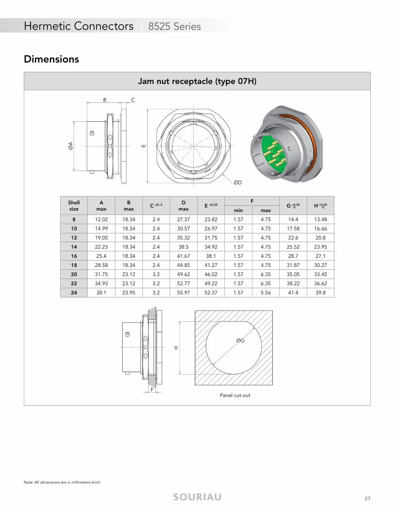
Note: All dimensions are in millimeters (mm)
ØA
ØD
B C
E
ØG
F
H
Panel cut-out
Shellsize
Amax
Bmax
C ±0.-5 Dmax
E ±0.25F
G +0.25 H +0.25
min max
8 12.02 18.34 2.4 27.37 23.82 1.57 4.75 14.4 13.48
10 14.99 18.34 2.4 30.57 26.97 1.57 4.75 17.58 16.66
12 19.05 18.34 2.4 35.32 31.75 1.57 4.75 22.6 20.8
14 22.23 18.34 2.4 38.5 34.92 1.57 4.75 25.52 23.95
16 25.4 18.34 2.4 41.67 38.1 1.57 4.75 28.7 27.1
18 28.58 18.34 2.4 44.85 41.27 1.57 4.75 31.87 30.27
20 31.75 23.12 3.2 49.62 46.02 1.57 6.35 35.05 33.45
22 34.93 23.12 3.2 52.77 49.22 1.57 6.35 38.22 36.62
24 38.1 23.95 3.2 55.97 52.37 1.57 5.56 41.4 39.8
-0 -0
Jam nut receptacle (type 07H)
Dimensions
28
Hermetic Connectors | 8525 Series
Note: All dimensions are in millimeters (mm)
Type 02H: Square fl ange receptacle Type 07H: Jam nut receptacleType IH: Solder mount receptacle
WXY
ØZ
WXY
ØZ
W
X
Y
ØZ
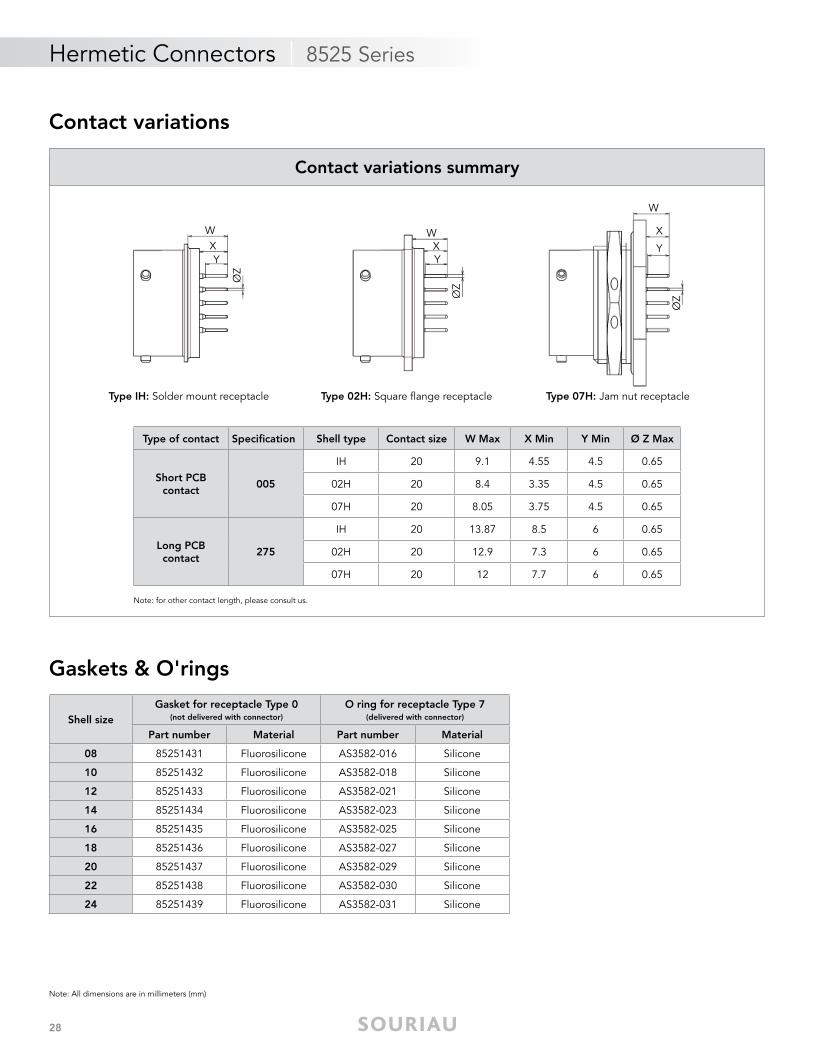
Gaskets & O'rings
Shell sizeGasket for receptacle Type 0
(not delivered with connector)
O ring for receptacle Type 7(delivered with connector)
Part number Material Part number Material
08 85251431 Fluorosilicone AS3582-016 Silicone
10 85251432 Fluorosilicone AS3582-018 Silicone
12 85251433 Fluorosilicone AS3582-021 Silicone
14 85251434 Fluorosilicone AS3582-023 Silicone
16 85251435 Fluorosilicone AS3582-025 Silicone
18 85251436 Fluorosilicone AS3582-027 Silicone
20 85251437 Fluorosilicone AS3582-029 Silicone
22 85251438 Fluorosilicone AS3582-030 Silicone
24 85251439 Fluorosilicone AS3582-031 Silicone
Type of contact Specifi cation Shell type Contact size W Max X Min Y Min Ø Z Max
Short PCB contact
005
IH 20 9.1 4.55 4.5 0.65
02H 20 8.4 3.35 4.5 0.65
07H 20 8.05 3.75 4.5 0.65
Long PCB contact
275
IH 20 13.87 8.5 6 0.65
02H 20 12.9 7.3 6 0.65
07H 20 12 7.7 6 0.65
Contact variations summary
Note: for other contact length, please consult us.
Contact variations
29
Hermetic Connectors | 8526 Series
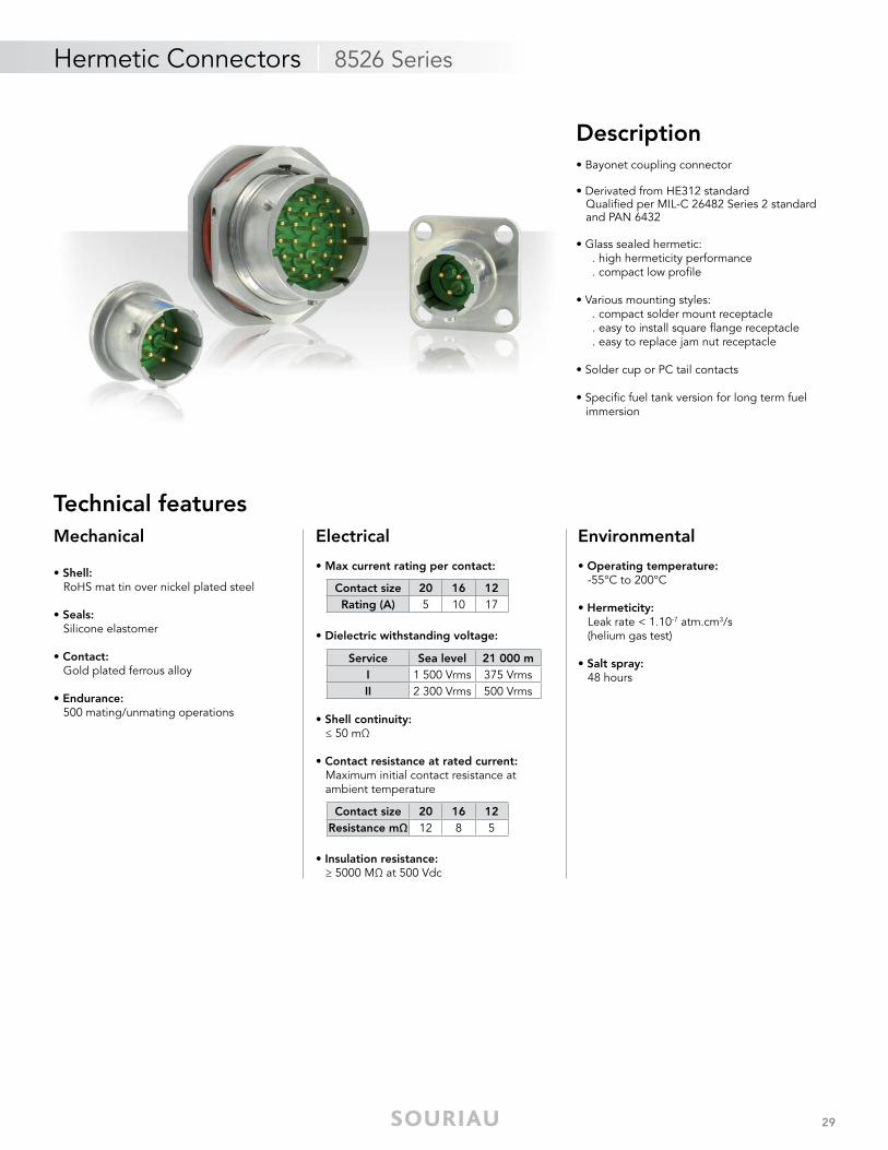
Mechanical
• Shell: RoHS mat tin over nickel plated steel
• Seals: Silicone elastomer
• Contact: Gold plated ferrous alloy
• Endurance: 500 mating/unmating operations
Electrical
• Max current rating per contact:
• Dielectric withstanding voltage:
• Shell continuity: ≤ 50 mΩ
• Contact resistance at rated current: Maximum initial contact resistance at ambient temperature
• Insulation resistance: ≥ 5000 MΩ at 500 Vdc
Environmental
• Operating temperature: -55°C to 200°C
• Hermeticity: Leak rate < 1.10-7 atm.cm3/s (helium gas test)
• Salt spray: 48 hours
Description• Bayonet coupling connector
• Derivated from HE312 standard Qualifi ed per MIL-C 26482 Series 2 standard and PAN 6432
• Glass sealed hermetic: . high hermeticity performance . compact low profi le
• Various mounting styles: . compact solder mount receptacle . easy to install square fl ange receptacle . easy to replace jam nut receptacle
• Solder cup or PC tail contacts
• Specifi c fuel tank version for long term fuel immersion
Technical features
Service Sea level 21 000 mI 1 500 Vrms 375 VrmsII 2 300 Vrms 500 Vrms
Contact size 20 16 12Rating (A) 5 10 17
Contact size 20 16 12Resistance mΩ 12 8 5
30
Hermetic Connectors | 8526 Series
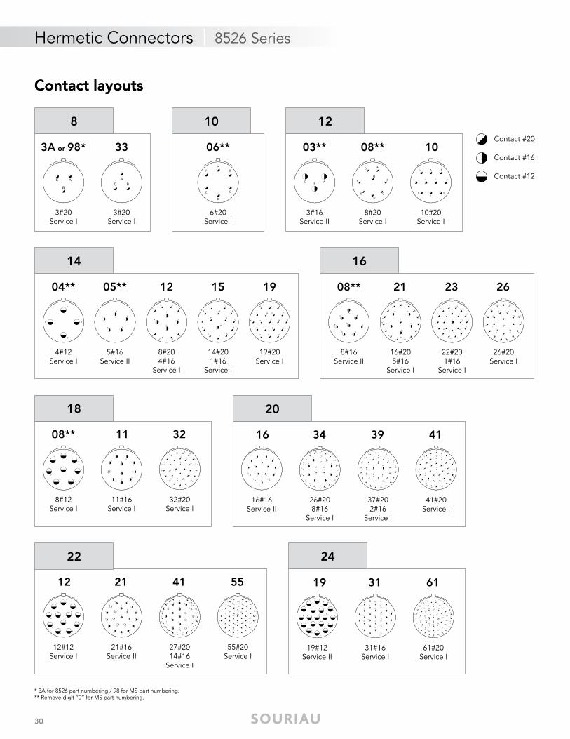
Contact layouts
* 3A for 8526 part numbering / 98 for MS part numbering.** Remove digit ‘‘0’’ for MS part numbering.
Contact layouts
3A or 98*
3#20Service I
33
3#20Service I
8
04**
4#12 Service I
05**
5#16 Service II
12
8#204#16
Service I
15
14#201#16
Service I
19
19#20 Service I
14 16
08**
8#16 Service II
21
16#205#16
Service I
26
26#20 Service I
23
22#20 1#16
Service I
18
08**
8#12 Service I
11
11#16 Service I
32
32#20 Service I
20
16
16#16 Service II
39
37#202#16
Service I
41
41#20 Service I
34
26#208#16
Service I
06**
6#20Service I
10 12
03**
3#16Service II
10
10#20Service I
08**
8#20Service I
24
19
19#12 Service II
31
31#16 Service I
61
61#20 Service I
22
12
12#12 Service I
21
21#16 Service II
41 55
27#2014#16
Service I
55#20 Service I
Contact #20
Contact #16
Contact #12
31
Hermetic Connectors | 8526 Series
Contact layouts (matrix)
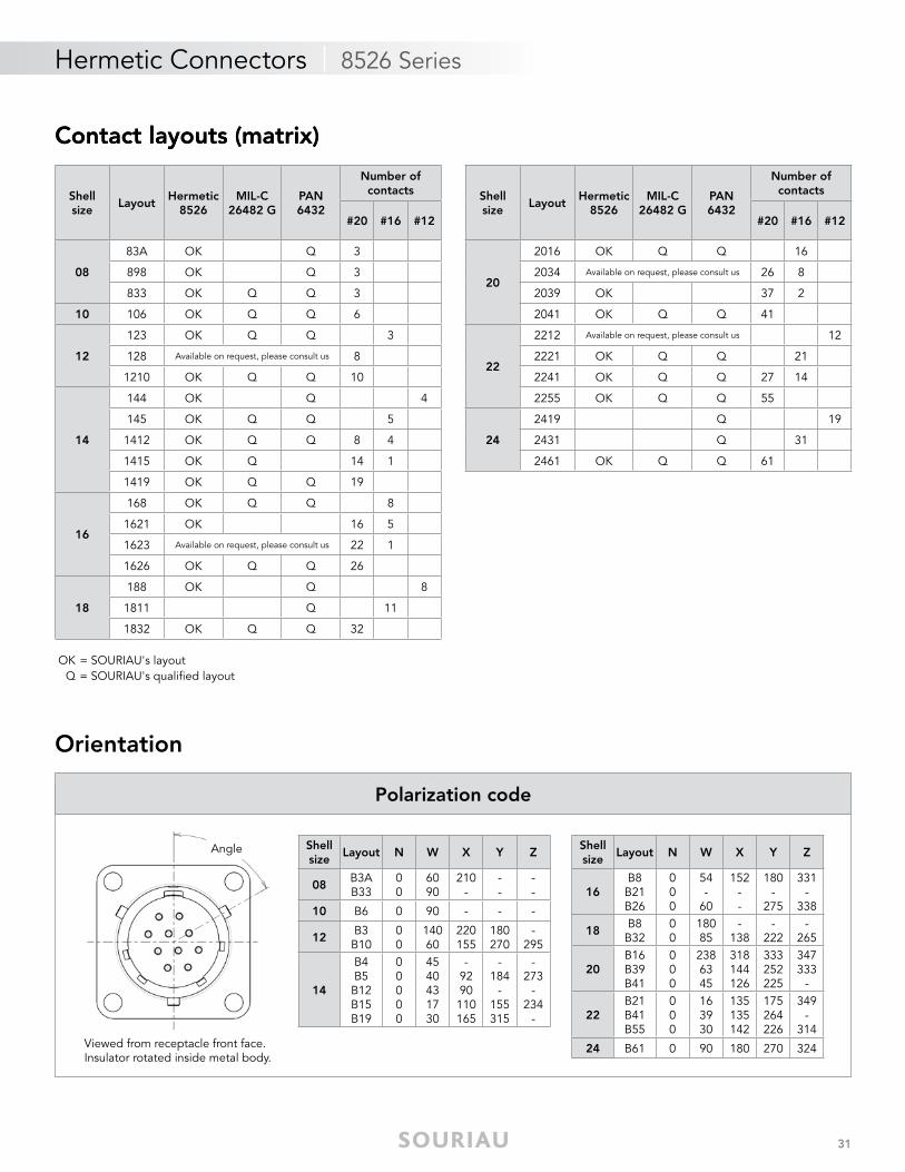
Orientation
Shell size
Layout N W X Y Z
08B3AB33
00
6090
210-
--
--
10 B6 0 90 - - -
12B3B10
00
14060
220155
180270
-295
14
B4B5B12B15B19
00000
4540431730
-9290110165
-184
-155315
-273
-234
-
Shell size
Layout N W X Y Z
16B8B21B26
000
54-
60
152--
180-
275
331-
338
18B8B32
00
18085
-138
-222
-265
20B16B39B41
000
2386345
318144126
333252225
347333
-
22B21B41B55
000
163930
135135142
175264226
349-
314
24 B61 0 90 180 270 324
Polarization code
Viewed from receptacle front face.Insulator rotated inside metal body.
Angle
Contact layouts (matrix)
OK = SOURIAU's layoutQ = SOURIAU's qualifi ed layout
Shellsize
LayoutHermetic
8526MIL-C
26482 GPAN6432
Number of contacts
#20 #16 #12
08
83A OK Q 3
898 OK Q 3
833 OK Q Q 3
10 106 OK Q Q 6
12
123 OK Q Q 3
128 Available on request, please consult us 8
1210 OK Q Q 10
14
144 OK Q 4
145 OK Q Q 5
1412 OK Q Q 8 4
1415 OK Q 14 1
1419 OK Q Q 19
16
168 OK Q Q 8
1621 OK 16 5
1623 Available on request, please consult us 22 1
1626 OK Q Q 26
18
188 OK Q 8
1811 Q 11
1832 OK Q Q 32
Shellsize
LayoutHermetic
8526MIL-C
26482 GPAN6432
Number of contacts
#20 #16 #12
20
2016 OK Q Q 16
2034 Available on request, please consult us 26 8
2039 OK 37 2
2041 OK Q Q 41
22
2212 Available on request, please consult us 12
2221 OK Q Q 21
2241 OK Q Q 27 14
2255 OK Q Q 55
24
2419 Q 19
2431 Q 31
2461 OK Q Q 61
32
Hermetic Connectors | 8526 Series
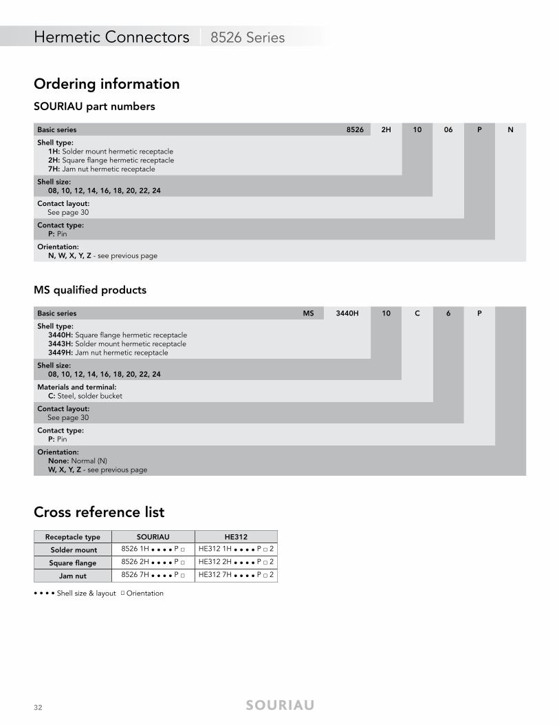
Ordering informationSOURIAU part numbers
MS qualifi ed products
Cross reference list
• • • • Shell size & layout □ Orientation
Basic series 8526 2H 10 06 P N
Shell type: 1H: Solder mount hermetic receptacle 2H: Square fl ange hermetic receptacle 7H: Jam nut hermetic receptacle
Shell size: 08, 10, 12, 14, 16, 18, 20, 22, 24
Contact layout: See page 30
Contact type: P: Pin
Orientation: N, W, X, Y, Z - see previous page
Basic series MS 3440H 10 C 6 P
Shell type: 3440H: Square fl ange hermetic receptacle 3443H: Solder mount hermetic receptacle 3449H: Jam nut hermetic receptacle
Shell size: 08, 10, 12, 14, 16, 18, 20, 22, 24
Materials and terminal: C: Steel, solder bucket
Contact layout: See page 30
Contact type: P: Pin
Orientation: None: Normal (N) W, X, Y, Z - see previous page
Receptacle type SOURIAU HE312
Solder mount 8526 1H • • • • P □ HE312 1H • • • • P □ 2
Square fl ange 8526 2H • • • • P □ HE312 2H • • • • P □ 2
Jam nut 8526 7H • • • • P □ HE312 7H • • • • P □ 2
33
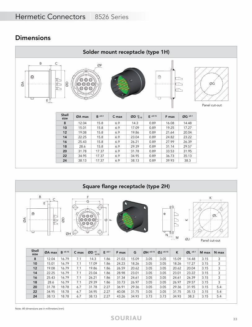
Hermetic Connectors | 8526 Series
Dimensions
Note: All dimensions are in millimeters (mm)
ØA
ØD
ØFB C
E
ØG
Panel cut-out
Shellsize ØA max B ±0.3 C max ØD +0 E ±0.15 F max ØG ±0.1
8 12.04 15.8 6.9 14.3 0.89 16.08 14.4810 15.01 15.8 6.9 17.09 0.89 19.25 17.2712 19.08 15.8 6.9 19.86 0.89 21.64 20.0414 22.25 15.8 6.9 23.04 0.89 24.82 23.2216 25.43 15.8 6.9 26.21 0.89 27.99 26.3918 28.6 15.8 6.9 29.39 0.89 31.14 29.5720 31.78 17.37 6.9 31.78 0.89 33.53 31.9522 34.95 17.37 6.9 34.95 0.89 36.73 35.1324 38.13 17.37 6.9 38.13 0.89 39.93 38.3
-0.15
Solder mount receptacle (type 1H)
ØA
ØD
ØH
BC
E
FG
FG
ØJN
K
M
ØL
K
Panel cut-out
Shellsize ØA max B ±0.15 C max ØD +0 E ±0.1 F max G ØH ±0.15 ØJ ±0.15 K ØL ±0.1 M max N max
8 12.04 16.79 7.1 14.3 1.86 21.03 15.09 3.05 3.05 15.09 14.48 3.15 310 15.01 16.79 7.1 17.09 1.86 24.23 18.26 3.05 3.05 18.26 17.27 3.15 312 19.08 16.79 7.1 19.86 1.86 26.59 20.62 3.05 3.05 20.62 20.04 3.15 314 22.25 16.79 7.1 23.04 1.86 28.98 23.01 3.05 3.05 23.01 23.22 3.15 316 25.43 16.79 7.1 26.21 1.86 31.34 24.61 3.05 3.05 24.61 26.39 3.15 318 28.6 16.79 7.1 29.39 1.86 33.73 26.97 3.05 3.05 26.97 29.57 3.15 320 31.78 18.78 6.7 31.78 2.27 36.91 29.36 3.05 3.05 29.36 31.95 3.15 5.422 34.95 18.78 6.7 34.95 2.27 40.08 31.75 3.05 3.05 31.75 35.13 3.15 5.424 38.13 18.78 6.7 38.13 2.27 43.26 34.93 3.73 3.73 34.93 38.3 3.15 5.4
-0.15
Square fl ange receptacle (type 2H)
34
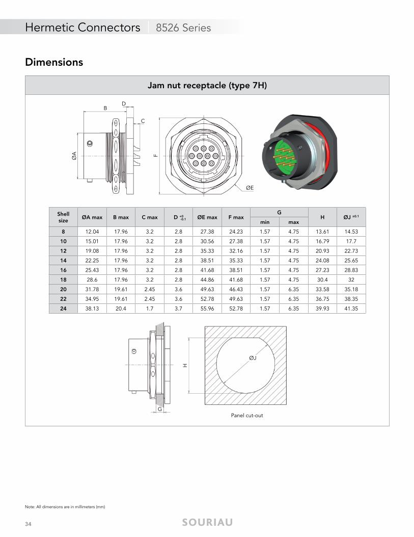
Hermetic Connectors | 8526 Series
Note: All dimensions are in millimeters (mm)
ØJ
G
H
Panel cut-out
Shellsize
ØA max B max C max D +0 ØE max F maxG
H ØJ ±0.1
min max
8 12.04 17.96 3.2 2.8 27.38 24.23 1.57 4.75 13.61 14.53
10 15.01 17.96 3.2 2.8 30.56 27.38 1.57 4.75 16.79 17.7
12 19.08 17.96 3.2 2.8 35.33 32.16 1.57 4.75 20.93 22.73
14 22.25 17.96 3.2 2.8 38.51 35.33 1.57 4.75 24.08 25.65
16 25.43 17.96 3.2 2.8 41.68 38.51 1.57 4.75 27.23 28.83
18 28.6 17.96 3.2 2.8 44.86 41.68 1.57 4.75 30.4 32
20 31.78 19.61 2.45 3.6 49.63 46.43 1.57 6.35 33.58 35.18
22 34.95 19.61 2.45 3.6 52.78 49.63 1.57 6.35 36.75 38.35
24 38.13 20.4 1.7 3.7 55.96 52.78 1.57 6.35 39.93 41.35
-0.1
ØA
ØE
B
C
F
D
Jam nut receptacle (type 7H)
Dimensions
35
Hermetic Connectors | 8526 Series
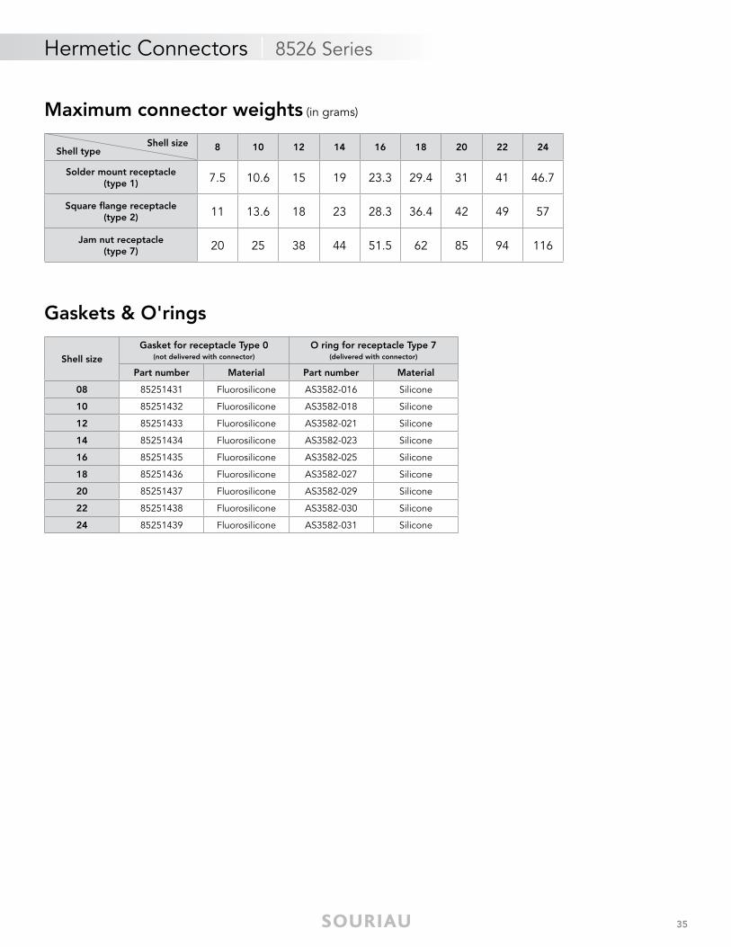
Maximum connector weights (in grams)
Shell size Shell type 8 10 12 14 16 18 20 22 24
Solder mount receptacle(type 1) 7.5 10.6 15 19 23.3 29.4 31 41 46.7
Square fl ange receptacle(type 2) 11 13.6 18 23 28.3 36.4 42 49 57
Jam nut receptacle(type 7) 20 25 38 44 51.5 62 85 94 116
Shell sizeGasket for receptacle Type 0
(not delivered with connector)
O ring for receptacle Type 7(delivered with connector)
Part number Material Part number Material
08 85251431 Fluorosilicone AS3582-016 Silicone
10 85251432 Fluorosilicone AS3582-018 Silicone
12 85251433 Fluorosilicone AS3582-021 Silicone
14 85251434 Fluorosilicone AS3582-023 Silicone
16 85251435 Fluorosilicone AS3582-025 Silicone
18 85251436 Fluorosilicone AS3582-027 Silicone
20 85251437 Fluorosilicone AS3582-029 Silicone
22 85251438 Fluorosilicone AS3582-030 Silicone
24 85251439 Fluorosilicone AS3582-031 Silicone
Gaskets & O'rings
36
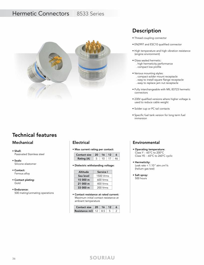
Hermetic Connectors | 8533 Series
Mechanical
• Shell: Passivated Stainless steel
• Seals: Silicone elastomer
• Contact: Ferrous alloy
• Contact plating: Gold
• Endurance: 500 mating/unmating operations
Electrical
• Max current rating per contact:
• Dielectric withstanding voltage:
• Contact resistance at rated current: Maximum initial contact resistance at ambiant temperature
Environmental
• Operating temperature: Class Y : -65°C to 200°C Class YE : -65°C to 260°C cyclic
• Hermeticity: Leak rate < 1.10-7 atm.cm3/s (helium gas test) • Salt spray: 500 hours
Description• Thread coupling connector
• EN2997 and ESC10 qualifi ed connector
• High temperature and high vibration resistance (engine environment)
• Glass sealed hermetic: . high hermeticity performance . compact low profi le
• Various mounting styles: . compact solder mount receptacle . easy to install square fl ange receptacle . easy to replace jam nut receptacle
• Fully interchangeable with MIL 83723 hermetic connectors
• 230V qualifi ed versions where higher voltage is used to reduce cable weight
• Solder cup or PC tail contacts
• Specifi c fuel tank version for long term fuel immersion
Technical features
Altitude Service ISea level 1500 Vrms15 000 m 600 Vrms21 000 m 400 Vrms33 000 m 200 Vrms
Contact size 20 16 12 6Rating (A) 5 10 17 46
Contact size 20 16 12 6Resistance mΩ 12 8.5 5 2
37
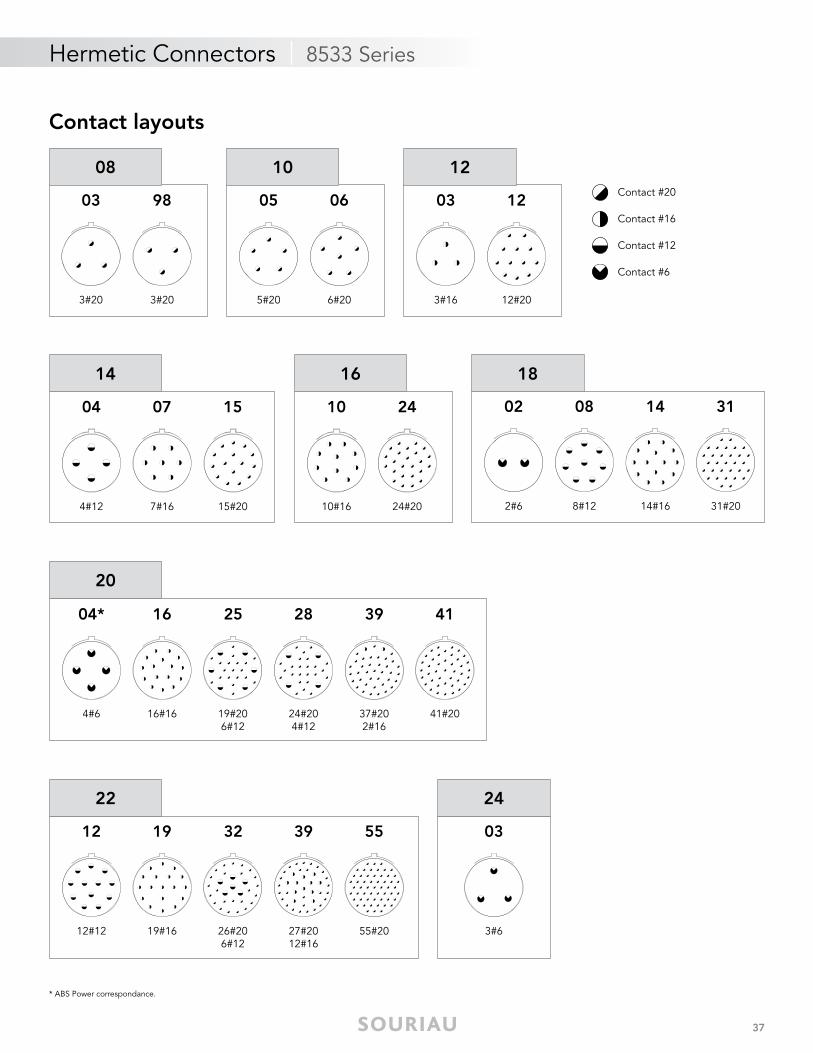
Hermetic Connectors | 8533 Series
Contact layouts
12
12#20
03
3#16
12
0605
6#205#20
10
03
3#20
08
98
3#20
04
4#12
07
7#16
15
15#20
14
24
24#20
10
10#16
16
02
2#6
08
8#12
14
14#16
18
31
31#20
22
12
12#12
19
19#16
32
26#206#12
55
55#2027#2012#16
39
20
37#202#16
04*
4#6
16
16#16
25
19#206#12
24#204#12
28 39 41
41#20
* ABS Power correspondance.
24
03
3#6
Contact #20
Contact #16
Contact #12
Contact #6
38
Hermetic Connectors | 8533 Series
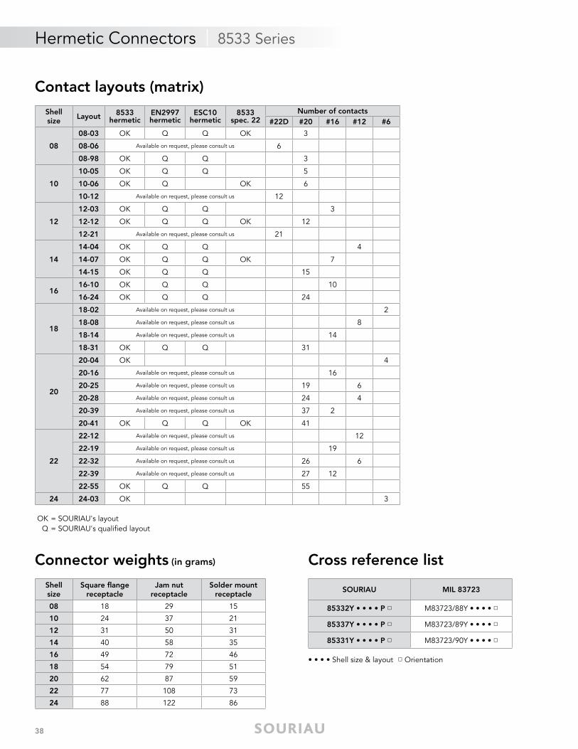
Contact layouts (matrix)
Cross reference list
• • • • Shell size & layout □ Orientation
Connector weights (in grams)
SOURIAU MIL 83723
85332Y • • • • P □ M83723/88Y • • • • □
85337Y • • • • P □ M83723/89Y • • • • □
85331Y • • • • P □ M83723/90Y • • • • □
Shell size
Square fl ange receptacle
Jam nutreceptacle
Solder mount receptacle
08 18 29 15
10 24 37 21
12 31 50 31
14 40 58 35
16 49 72 46
18 54 79 51
20 62 87 59
22 77 108 73
24 88 122 86
OK = SOURIAU's layoutQ = SOURIAU's qualifi ed layout
Shellsize
Layout 8533hermetic
EN2997hermetic
ESC10hermetic
8533spec. 22
Number of contacts#22D #20 #16 #12 #6
08
08-03 OK Q Q OK 3
08-06 Available on request, please consult us 6
08-98 OK Q Q 3
10
10-05 OK Q Q 5
10-06 OK Q OK 6
10-12 Available on request, please consult us 12
12
12-03 OK Q Q 3
12-12 OK Q Q OK 12
12-21 Available on request, please consult us 21
14
14-04 OK Q Q 4
14-07 OK Q Q OK 7
14-15 OK Q Q 15
1616-10 OK Q Q 10
16-24 OK Q Q 24
18
18-02 Available on request, please consult us 2
18-08 Available on request, please consult us 8
18-14 Available on request, please consult us 14
18-31 OK Q Q 31
20
20-04 OK 4
20-16 Available on request, please consult us 16
20-25 Available on request, please consult us 19 6
20-28 Available on request, please consult us 24 4
20-39 Available on request, please consult us 37 2
20-41 OK Q Q OK 41
22
22-12 Available on request, please consult us 12
22-19 Available on request, please consult us 19
22-32 Available on request, please consult us 26 6
22-39 Available on request, please consult us 27 12
22-55 OK Q Q 55
24 24-03 OK 3
39
Hermetic Connectors | 8533 Series
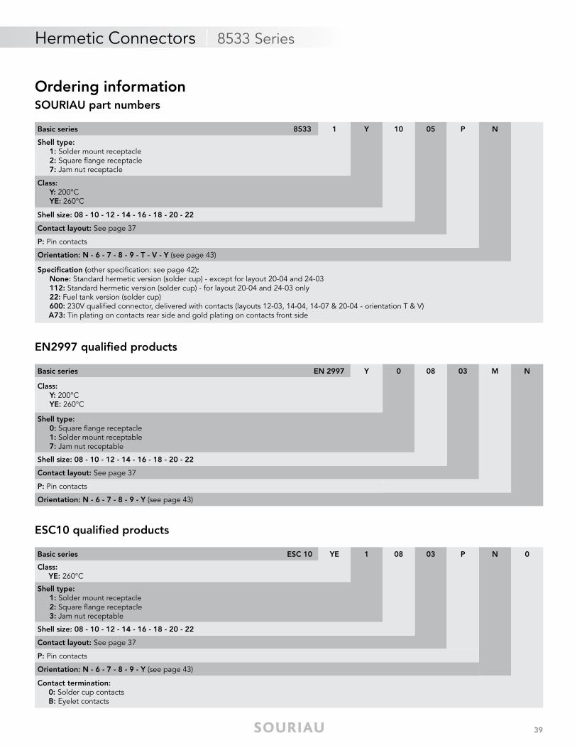
Ordering informationSOURIAU part numbers
EN2997 qualified products
ESC10 qualified products
Basic series 8533 1 Y 10 05 P N
Shell type: 1: Solder mount receptacle 2: Square flange receptacle 7: Jam nut receptacle
Class:Y: 200°CYE: 260°C
Shell size: 08 - 10 - 12 - 14 - 16 - 18 - 20 - 22
Contact layout: See page 37
P: Pin contacts
Orientation: N - 6 - 7 - 8 - 9 - T - V - Y (see page 43)
Specification (other specification: see page 42):None: Standard hermetic version (solder cup) - except for layout 20-04 and 24-03112: Standard hermetic version (solder cup) - for layout 20-04 and 24-03 only22: Fuel tank version (solder cup)600: 230V qualifi ed connector, delivered with contacts (layouts 12-03, 14-04, 14-07 & 20-04 - orientation T & V)
A73: Tin plating on contacts rear side and gold plating on contacts front side
Basic series EN 2997 Y 0 08 03 M N
Class:Y: 200°CYE: 260°C
Shell type: 0: Square flange receptacle1: Solder mount receptable7: Jam nut receptable
Shell size: 08 - 10 - 12 - 14 - 16 - 18 - 20 - 22
Contact layout: See page 37
P: Pin contacts
Orientation: N - 6 - 7 - 8 - 9 - Y (see page 43)
Basic series ESC 10 YE 1 08 03 P N 0
Class: YE: 260°C
Shell type:1: Solder mount receptacle 2: Square flange receptacle 3: Jam nut receptable
Shell size: 08 - 10 - 12 - 14 - 16 - 18 - 20 - 22
Contact layout: See page 37
P: Pin contacts
Orientation: N - 6 - 7 - 8 - 9 - Y (see page 43)
Contact termination: 0: Solder cup contacts B: Eyelet contacts
40
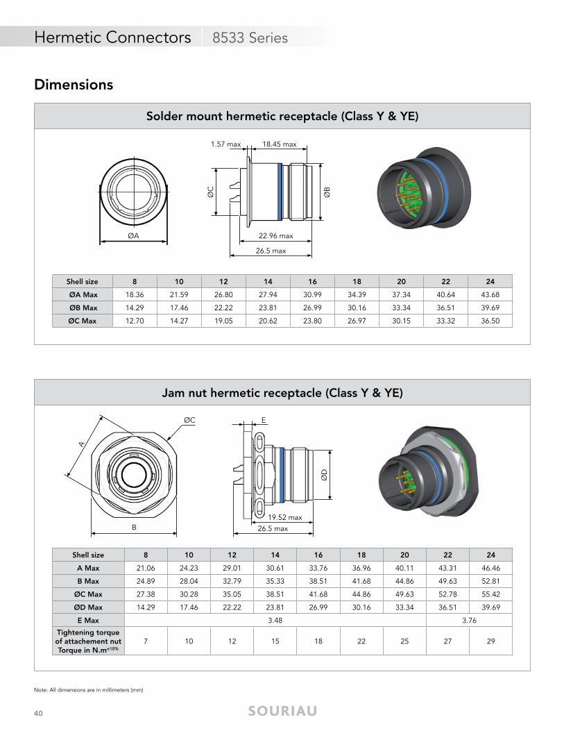
Hermetic Connectors | 8533 Series
Note: All dimensions are in millimeters (mm)
Dimensions
ØA
Shell size 8 10 12 14 16 18 20 22 24
ØA Max 18.36 21.59 26.80 27.94 30.99 34.39 37.34 40.64 43.68
ØB Max 14.29 17.46 22.22 23.81 26.99 30.16 33.34 36.51 39.69
ØC Max 12.70 14.27 19.05 20.62 23.80 26.97 30.15 33.32 36.50
Solder mount hermetic receptacle (Class Y & YE)
1.57 max 18.45 max
22.96 max
ØB
ØC
26.5 max
Shell size 8 10 12 14 16 18 20 22 24
A Max 21.06 24.23 29.01 30.61 33.76 36.96 40.11 43.31 46.46
B Max 24.89 28.04 32.79 35.33 38.51 41.68 44.86 49.63 52.81
ØC Max 27.38 30.28 35.05 38.51 41.68 44.86 49.63 52.78 55.42
ØD Max 14.29 17.46 22.22 23.81 26.99 30.16 33.34 36.51 39.69
E Max 3.48 3.76
Tightening torqueof attachement nutTorque in N.m±10%
7 10 12 15 18 22 25 27 29
Jam nut hermetic receptacle (Class Y & YE)
E
ØD
19.52 max26.5 max
ØC
B
A
41
Hermetic Connectors | 8533 Series
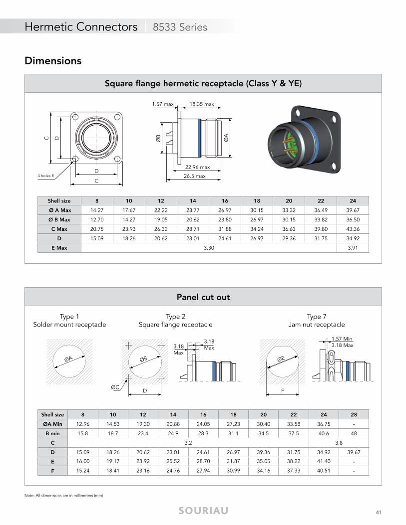
Note: All dimensions are in millimeters (mm)
Shell size 8 10 12 14 16 18 20 22 24 28
ØA Min 12.96 14.53 19.30 20.88 24.05 27.23 30.40 33.58 36.75 -
B min 15.8 18.7 23.4 24.9 28.3 31.1 34.5 37.5 40.6 48
C 3.2 3.8
D 15.09 18.26 20.62 23.01 24.61 26.97 39.36 31.75 34.92 39.67
E 16.00 19.17 23.92 25.52 28.70 31.87 35.05 38.22 41.40 -
F 15.24 18.41 23.16 24.76 27.94 30.99 34.16 37.33 40.51 -
Panel cut out
Type 1Solder mount receptacle
ØA
Type 2Square flange receptacle
ØCD
ØB
3.18 Max3.18
Max
Type 7Jam nut receptacle
ØE
F
1.57 Min3.18 Max
Dimensions
4 holes EC
D
C D
1.57 max 18.35 max
22.96 max
26.5 max
ØA
ØB
Shell size 8 10 12 14 16 18 20 22 24
Ø A Max 14.27 17.67 22.22 23.77 26.97 30.15 33.32 36.49 39.67
Ø B Max 12.70 14.27 19.05 20.62 23.80 26.97 30.15 33.82 36.50
C Max 20.75 23.93 26.32 28.71 31.88 34.24 36.63 39.80 43.36
D 15.09 18.26 20.62 23.01 24.61 26.97 29.36 31.75 34.92
E Max 3.30 3.91
Square fl ange hermetic receptacle (Class Y & YE)
42
Hermetic Connectors | 8533 Series
Note: All dimensions are in millimeters (mm)
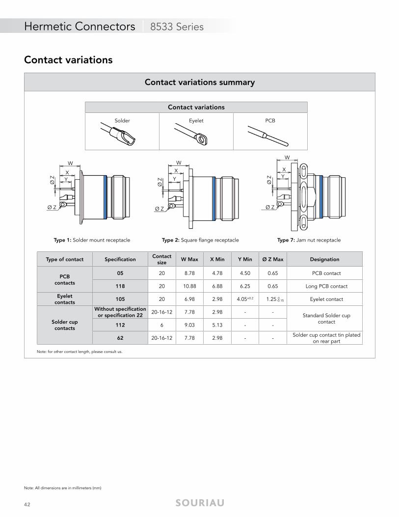
Contact variations
Solder Eyelet PCB
Contact variations
Type of contact Specifi cationContact
sizeW Max X Min Y Min Ø Z Max Designation
PCBcontacts
05 20 8.78 4.78 4.50 0.65 PCB contact
118 20 10.88 6.88 6.25 0.65 Long PCB contact
Eyeletcontacts
105 20 6.98 2.98 4.05±0.2 1.25 0 Eyelet contact
Solder cupcontacts
Without specifi cationor specifi cation 22
20-16-12 7.78 2.98 - -Standard Solder cup
contact112 6 9.03 5.13 - -
62 20-16-12 7.78 2.98 - - Solder cup contact tin platedon rear part
-0.15
Type 1: Solder mount receptacle Type 2: Square flange receptacle Type 7: Jam nut receptacle
Y
Ø Z
Ø Z
X
W
Y
Ø Z
Ø Z
X
W
Y
Ø Z
Ø Z
X
W
Contact variations summary
Note: for other contact length, please consult us.
43
Hermetic Connectors | 8533 Series
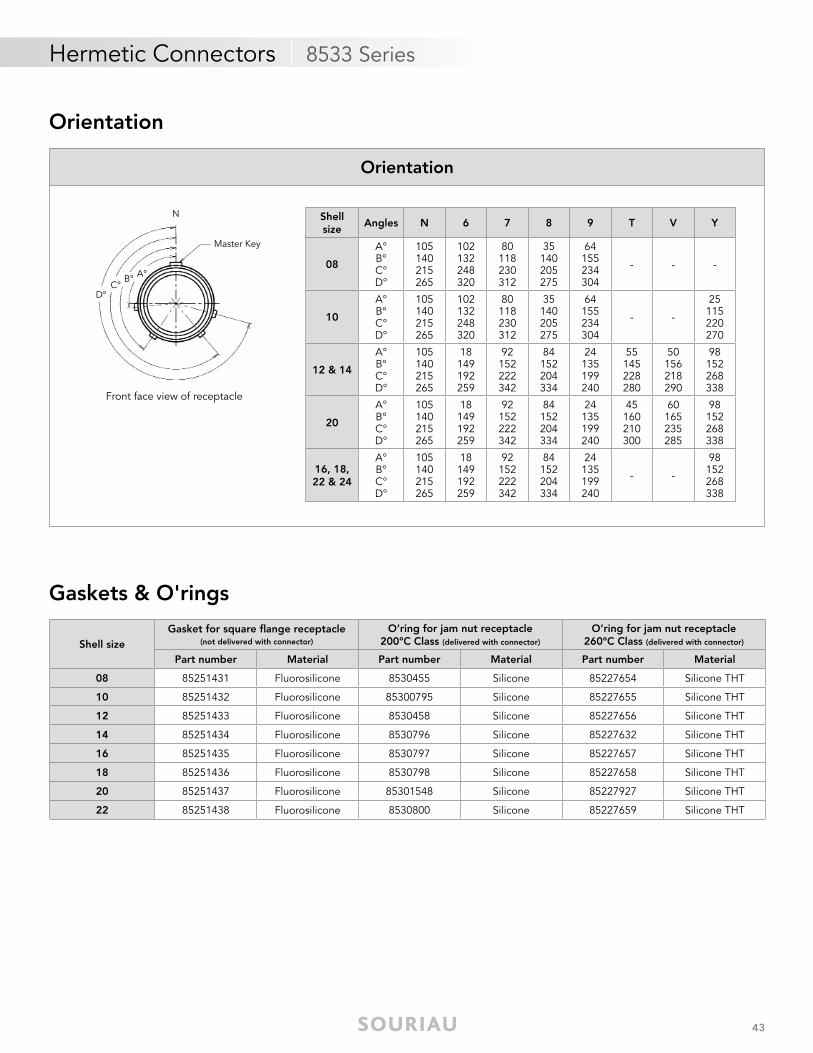
Front face view of receptacle
N
A°B°
D°C°
Master Key
Orientation
Shell sizeGasket for square fl ange receptacle
(not delivered with connector)
O’ring for jam nut receptacle200°C Class (delivered with connector)
O’ring for jam nut receptacle260°C Class (delivered with connector)
Part number Material Part number Material Part number Material
08 85251431 Fluorosilicone 8530455 Silicone 85227654 Silicone THT
10 85251432 Fluorosilicone 85300795 Silicone 85227655 Silicone THT
12 85251433 Fluorosilicone 8530458 Silicone 85227656 Silicone THT
14 85251434 Fluorosilicone 8530796 Silicone 85227632 Silicone THT
16 85251435 Fluorosilicone 8530797 Silicone 85227657 Silicone THT
18 85251436 Fluorosilicone 8530798 Silicone 85227658 Silicone THT
20 85251437 Fluorosilicone 85301548 Silicone 85227927 Silicone THT
22 85251438 Fluorosilicone 8530800 Silicone 85227659 Silicone THT
Shell size
Angles N 6 7 8 9 T V Y
08
A°B°C°D°
105140215265
102132248320
80118230312
35140205275
64155234304
- - -
10
A°B°C°D°
105140215265
102132248320
80118230312
35140205275
64155234304
- -
25115220270
12 & 14
A°B°C°D°
105140215265
18149192259
92152222342
84152204334
24135199240
55145228280
50156218290
98152268338
20
A°B°C°D°
105140215265
18149192259
92152222342
84152204334
24135199240
45160210300
60165235285
98152268338
16, 18, 22 & 24
A°B°C°D°
105140215265
18149192259
92152222342
84152204334
24135199240
- -
98152268338
Orientation
Gaskets & O'rings
44
Hermetic Connectors | 8D Series
Mechanical
• Shell: Class Y: passivated stainless steel Class N: nickel plated stainless steel
• Seals: Silicone elastomer
• Contact: Gold plated ferrous alloy
• Endurance: 500 mating/unmating operations
Electrical
• Max current rating per contact:
• Dielectric withstanding voltage:
• Insulation resistance: 5000 MΩ (under 500 Vdc)
Environmental
• Operating temperature: -65°C to 200°C
• Hermeticity: Leak rate < 1.10-7 atm.cm3/s (helium gas test)
• Salt spray: Class Y: 500 hours Class N: 48 hours
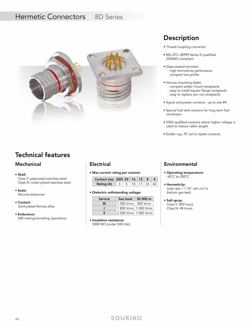
Description• Thread coupling connector
• MIL-DTL-38999 Series III qualifi ed EN3645 compliant
• Glass sealed hermetic: . high hermeticity perfomance . compact low profi le
• Various mounting styles: . compact solder mount receptacle . easy to install square fl ange receptacle . easy to replace jam nut receptacle
• Signal and power contacts - up to size #4
• Special fuel tank versions for long term fuel immersion
• 230V qualifi ed versions where higher voltage is used to reduce cable weight
• Solder cup, PC tail or eyelet contacts
Technical features
Contact size 22D 20 16 12 8 4Rating (A) 3 5 10 17 33 60
Service Sea level 30 000 mM 1 300 Vrms 800 VrmsI 1 800 Vrms 1 000 VrmsII 2 300 Vrms 1 000 Vrms
45
Hermetic Connectors | 8D Series
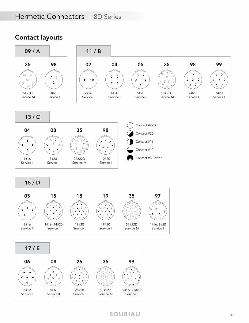
Contact layouts
35
6#22DService M
98
3#20Service I
09 / A 11 / B
02
2#16Service I
04
4#20Service I
05
5#20Service I
99
7#20Service I
35
13#22DService M
98
6#20Service I
04
4#16Service I
08
8#20Service I
35
22#22DService M
98
10#20Service I
13 / C
5#16Service II
05
1#16, 14#20Service I
15 18
18#20Service I
19
19#20Service I
35
37#22DService M
97
4#16, 8#20Service I
15 / D
17 / E
06
6#12Service I
08
8#16Service II
26
26#20Service I
99
2#16, 21#20Service I
35
55#22DService M
Contact #22D
Contact #20
Contact #16
Contact #12
Contact #8 Power
46
Hermetic Connectors | 8D Series
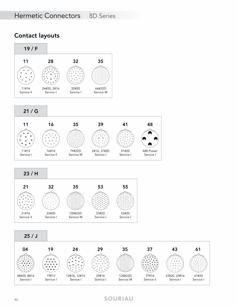
19 / F
11
11#16Service II
28
26#20, 2#16Service I
32
32#20Service I
35
66#22DService M
21 / G
11#12Service I
11 48
4#8 PowerService I
16#16Service II
16 35
79#22DService M
39
2#16, 37#20Service I
41
41#20Service I
23 / H
21#16Service II
21
32#20Service I
32 35
100#22DService M
53
53#20Service I
55
55#20Service I
25 / J
48#20, 8#16Service I
04 19
19#12Service I
29#16Service I
29
128#22DService M
35 37
37#16Service II
43
23#20, 20#16Service I
H
61#20Service I
6124
12#16, 12#12Service I
Contact layouts
47
Hermetic Connectors | 8D Series
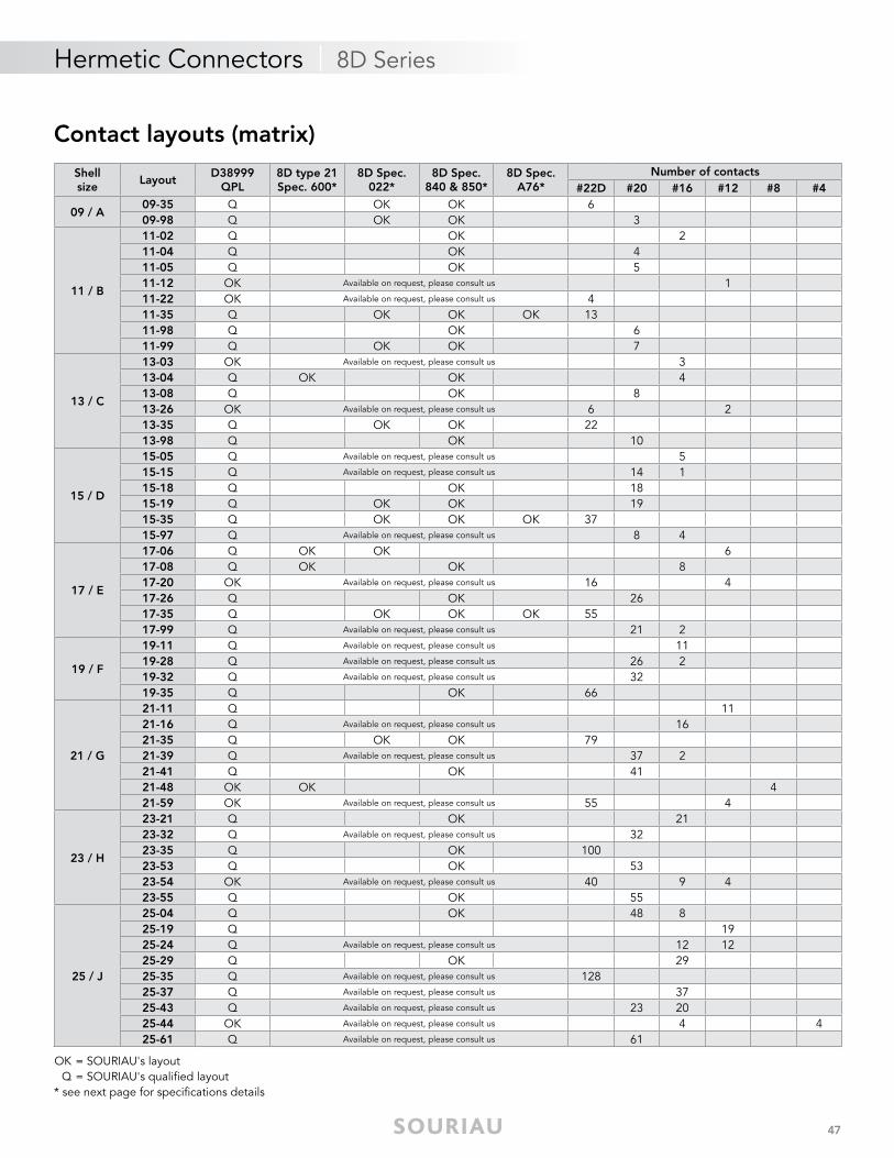
Contact layouts (matrix)
OK = SOURIAU's layoutQ = SOURIAU's qualifi ed layout
* see next page for specifi cations details
Shellsize
LayoutD38999
QPL8D type 21Spec. 600*
8D Spec.022*
8D Spec.840 & 850*
8D Spec.A76*
Number of contacts#22D #20 #16 #12 #8 #4
09 / A09-35 Q OK OK 609-98 Q OK OK 3
11 / B
11-02 Q OK 211-04 Q OK 411-05 Q OK 511-12 OK Available on request, please consult us 111-22 OK Available on request, please consult us 411-35 Q OK OK OK 1311-98 Q OK 611-99 Q OK OK 7
13 / C
13-03 OK Available on request, please consult us 313-04 Q OK OK 413-08 Q OK 813-26 OK Available on request, please consult us 6 213-35 Q OK OK 2213-98 Q OK 10
15 / D
15-05 Q Available on request, please consult us 515-15 Q Available on request, please consult us 14 115-18 Q OK 1815-19 Q OK OK 1915-35 Q OK OK OK 3715-97 Q Available on request, please consult us 8 4
17 / E
17-06 Q OK OK 617-08 Q OK OK 817-20 OK Available on request, please consult us 16 417-26 Q OK 2617-35 Q OK OK OK 5517-99 Q Available on request, please consult us 21 2
19 / F
19-11 Q Available on request, please consult us 1119-28 Q Available on request, please consult us 26 219-32 Q Available on request, please consult us 3219-35 Q OK 66
21 / G
21-11 Q 1121-16 Q Available on request, please consult us 1621-35 Q OK OK 7921-39 Q Available on request, please consult us 37 221-41 Q OK 4121-48 OK OK 421-59 OK Available on request, please consult us 55 4
23 / H
23-21 Q OK 2123-32 Q Available on request, please consult us 3223-35 Q OK 10023-53 Q OK 5323-54 OK Available on request, please consult us 40 9 423-55 Q OK 55
25 / J
25-04 Q OK 48 825-19 Q 1925-24 Q Available on request, please consult us 12 1225-29 Q OK 2925-35 Q Available on request, please consult us 12825-37 Q Available on request, please consult us 3725-43 Q Available on request, please consult us 23 2025-44 OK Available on request, please consult us 4 425-61 Q Available on request, please consult us 61
48
Hermetic Connectors | 8D Series
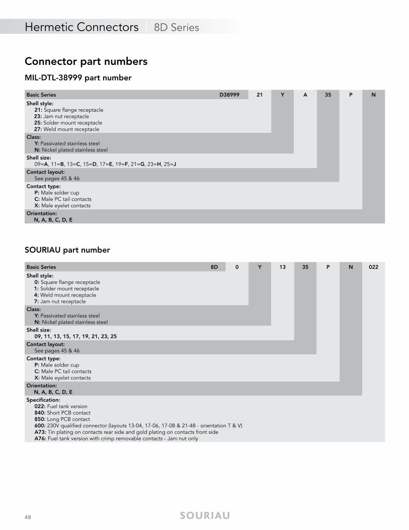
Connector part numbersMIL-DTL-38999 part number
SOURIAU part number
Basic Series D38999 21 Y A 35 P N
Shell style: 21: Square fl ange receptacle 23: Jam nut receptacle 25: Solder mount receptacle 27: Weld mount receptacleClass: Y: Passivated stainless steel N: Nickel plated stainless steelShell size: 09=A, 11=B, 13=C, 15=D, 17=E, 19=F, 21=G, 23=H, 25=JContact layout: See pages 45 & 46Contact type: P: Male solder cup C: Male PC tail contacts X: Male eyelet contactsOrientation: N, A, B, C, D, E
Basic Series 8D 0 Y 13 35 P N 022
Shell style: 0: Square fl ange receptacle 1: Solder mount receptacle 4: Weld mount receptacle 7: Jam nut receptacleClass: Y: Passivated stainless steel N: Nickel plated stainless steelShell size: 09, 11, 13, 15, 17, 19, 21, 23, 25Contact layout: See pages 45 & 46Contact type: P: Male solder cup C: Male PC tail contacts X: Male eyelet contactsOrientation: N, A, B, C, D, ESpecifi cation: 022: Fuel tank version 840: Short PCB contact 850: Long PCB contact 600: 230V qualifi ed connector (layouts 13-04, 17-06, 17-08 & 21-48 - orientation T & V) A73: Tin plating on contacts rear side and gold plating on contacts front side A76: Fuel tank version with crimp removable contacts - Jam nut only
49
Hermetic Connectors | 8D Series
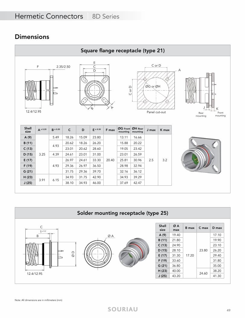
Note: All dimensions are in millimeters (mm)
Dimensions
AB
CD
EF 2.35/2.50
12.4/12.95 Panel cut-out
AC or D
C o
r D ØG or ØH
J KRear
mountingFront
mounting
Shell size A ± 0.20 B ± 0.20 C D E ± 0.30 F max ØG Front
mountingØH Rearmounting
J max K max
A (9)
3.25
5.49 18.26 15.09 23.80
20.40
13.11 16.66
2.5 3.2
B (11)4.93
20.62 18.26 26.20 15.88 20.22
C (13) 23.01 20.62 28.60 19.05 23.42
D (15) 4.39 24.61 23.01 31.00 23.01 26.59
E (17)
4.93
26.97 24.61 33.30 25.81 30.96
F (19) 29.36 26.97 36.50 28.98 32.94
G (21) 31.75 29.36 39.70 32.16 36.12
H (23)3.91 6.15
34.93 31.75 42.90 34.93 39.29
J (25) 38.10 34.93 46.00 37.69 42.47
Square fl ange receptacle (type 21)
B
C1± 0.2
Ø D
12.4/12.95
Ø A
Shell size
Ø A max
B max C max D max
A (9) 19.40
17.20
23.80
17.10
B (11) 21.80 19.90
C (13) 24.90 23.10
D (15) 28.10 26.20
E (17) 31.30 29.40
F (19) 33.60 31.80
G (21) 36.80 35.00
H (23) 40.0024.60
38.20
J (25) 43.20 41.30
Solder mounting receptacle (type 25)
50
Hermetic Connectors | 8D Series
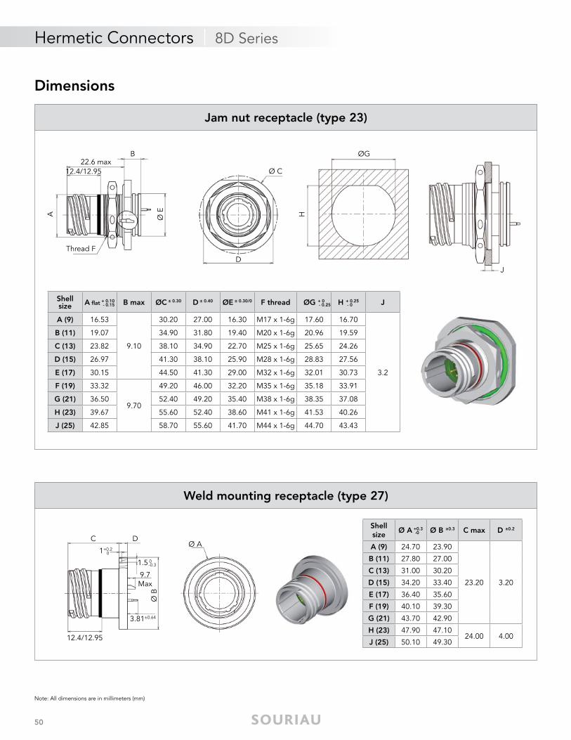
Note: All dimensions are in millimeters (mm)
A Ø E
22.6 maxB
Thread F
12.4/12.95
D
Ø C
ØG
H
J
Jam nut receptacle (type 23)
Shellsize A fl at + 0.10 B max ØC ± 0.30 D ± 0.40 ØE ± 0.30/0 F thread ØG + 0 H + 0.25 J
A (9) 16.53
9.10
30.20 27.00 16.30 M17 x 1-6g 17.60 16.70
3.2
B (11) 19.07 34.90 31.80 19.40 M20 x 1-6g 20.96 19.59
C (13) 23.82 38.10 34.90 22.70 M25 x 1-6g 25.65 24.26
D (15) 26.97 41.30 38.10 25.90 M28 x 1-6g 28.83 27.56
E (17) 30.15 44.50 41.30 29.00 M32 x 1-6g 32.01 30.73
F (19) 33.32
9.70
49.20 46.00 32.20 M35 x 1-6g 35.18 33.91
G (21) 36.50 52.40 49.20 35.40 M38 x 1-6g 38.35 37.08
H (23) 39.67 55.60 52.40 38.60 M41 x 1-6g 41.53 40.26
J (25) 42.85 58.70 55.60 41.70 M44 x 1-6g 44.70 43.43
- 0.15 - 0.25 - 0
Dimensions
DC
Ø B
12.4/12.95
Ø A1+0.2
0
1.5 0-0.3
9.7 Max
3.81±0.64
Shell size
Ø A +0.3 Ø B ±0.3 C max D ±0.2
A (9) 24.70 23.90
23.20 3.20
B (11) 27.80 27.00
C (13) 31.00 30.20
D (15) 34.20 33.40
E (17) 36.40 35.60
F (19) 40.10 39.30
G (21) 43.70 42.90
H (23) 47.90 47.1024.00 4.00
J (25) 50.10 49.30
-0
Weld mounting receptacle (type 27)
51
Hermetic Connectors | 8D Series
Note: All dimensions are in millimeters (mm)
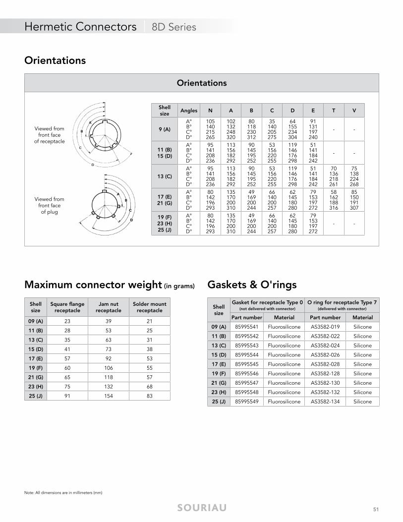
Maximum connector weight (in grams)
Shellsize
Square fl ange receptacle
Jam nutreceptacle
Solder mount receptacle
09 (A) 23 39 21
11 (B) 28 53 25
13 (C) 35 63 31
15 (D) 41 73 38
17 (E) 57 92 53
19 (F) 60 106 55
21 (G) 65 118 57
23 (H) 75 132 68
25 (J) 91 154 83
Shellsize
Gasket for receptacle Type 0(not delivered with connector)
O ring for receptacle Type 7(delivered with connector)
Part number Material Part number Material
09 (A) 85995541 Fluorosilicone AS3582-019 Silicone
11 (B) 85995542 Fluorosilicone AS3582-022 Silicone
13 (C) 85995543 Fluorosilicone AS3582-024 Silicone
15 (D) 85995544 Fluorosilicone AS3582-026 Silicone
17 (E) 85995545 Fluorosilicone AS3582-028 Silicone
19 (F) 85995546 Fluorosilicone AS3582-128 Silicone
21 (G) 85995547 Fluorosilicone AS3582-130 Silicone
23 (H) 85995548 Fluorosilicone AS3582-132 Silicone
25 (J) 85995549 Fluorosilicone AS3582-134 Silicone
Orientations
Viewed from front faceof plug
Viewed from front face
of receptacle
Shell size
Angles N A B C D E T V
9 (A)
A°B°C°D°
105140215265
102132248320
80118230312
35140205275
64155234304
91131197240
- -
11 (B) 15 (D)
A°B°C°D°
95141208236
113156182292
90145195252
53156220255
119146176298
51141184242
- -
13 (C)
A°B°C°D°
95141208236
113156182292
90145195252
53156220255
119146176298
51141184242
70136218261
75138224268
17 (E)21 (G)
A°B°C°D°
80142196293
135170200310
49169200244
66140200257
62145180280
79153197272
58162188316
85150191307
19 (F)23 (H)25 (J)
A°B°C°D°
80142196293
135170200310
49169200244
66140200257
62145180280
79153197272
- -
Orientations
Gaskets & O'rings
52
Hermetic Connectors | 8D Series
Note: All dimensions are in millimeters (mm)
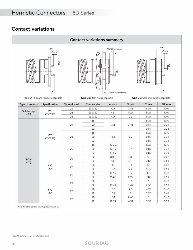
Contact variations
Type of contact Specifi cation Type of shell Contact size W max X min Y min ØZ max
Solder cup( P )
WF(F38999)
21 20 & 22 N/A 3.45 N/A N/A
23 20 & 22 4.5 N/A N/A N/A
25 20 & 22 N/A 2.3 N/A N/A
PCB( C )
WF(F38999)
21
16
6.65 3.45
N/A N/A
20 0.89 0.71
22 0.89 0.38
23
16
11.5 3.3
N/A N/A
20 0.89 0.71
22 0.89 0.38
25
16 10.75
3.4
N/A N/A
20 12.15 0.89 0.71
22 13.55 0.89 0.38
840(8D)
2120 8.05 4.85 4.5 0.62
22 7.32 4.12 3.82 0.53
2320 11.8 3.6 4.5 0.62
22 10.6 2.4 5.75 0.53
2520 10.15 3.7 4.5 0.62
22 9.42 2.97 3.82 0.53
850(8D)
2120 13 9.8 6 0.62
22 10.69 7.49 7.35 0.53
2320 15.3 7.1 6.25 0.62
22 16.2 8 9.25 0.45
2520 15.1 8.65 6 0.62
22 12.79 6.34 7.35 0.53
Contact variations summary
Type 25: Solder mount receptacleType 21: Square flange receptacle Type 23: Jam nut receptacle
X XW (Solder cup contacts)
WX Y
ØZ
W (PCB contacts)
X Y
ØZ
WX Y
ØZ
Note: for other contact length, please consult us.
53
Hermetic Connectors | 8STA Series
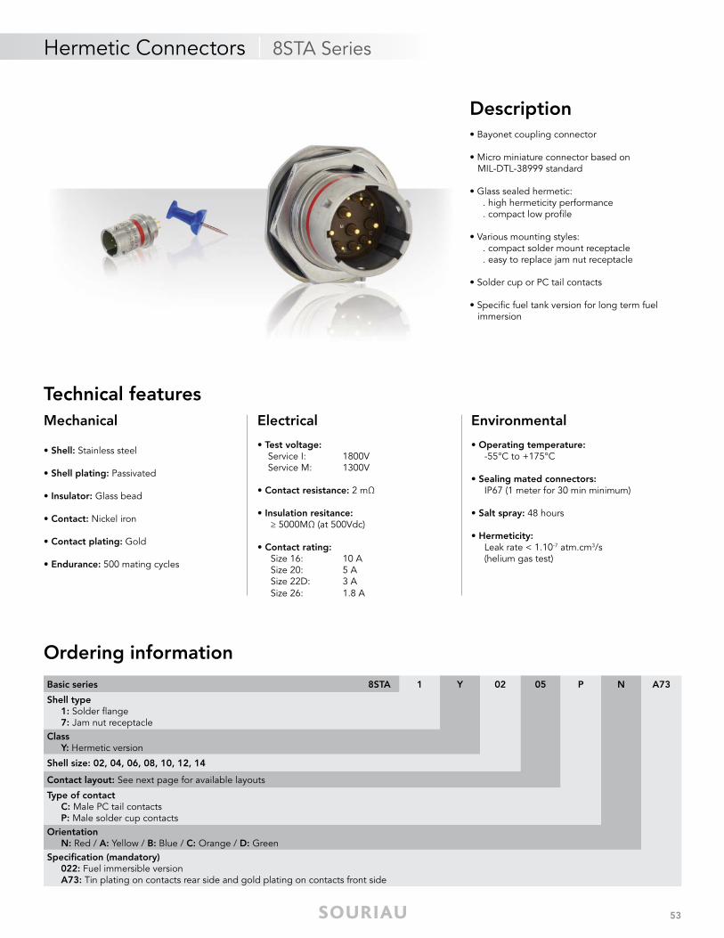
Mechanical
• Shell: Stainless steel
• Shell plating: Passivated
• Insulator: Glass bead
• Contact: Nickel iron
• Contact plating: Gold
• Endurance: 500 mating cycles
Electrical
• Test voltage: Service I: 1800V Service M: 1300V
• Contact resistance: 2 mΩ
• Insulation resitance: ≥ 5000MΩ (at 500Vdc)
• Contact rating: Size 16: 10 A Size 20: 5 A Size 22D: 3 A Size 26: 1.8 A
Environmental
• Operating temperature: -55°C to +175°C
• Sealing mated connectors: IP67 (1 meter for 30 min minimum) • Salt spray: 48 hours
• Hermeticity: Leak rate < 1.10-7 atm.cm3/s (helium gas test)
Description• Bayonet coupling connector
• Micro miniature connector based on MIL-DTL-38999 standard
• Glass sealed hermetic: . high hermeticity performance . compact low profi le
• Various mounting styles: . compact solder mount receptacle . easy to replace jam nut receptacle
• Solder cup or PC tail contacts
• Specifi c fuel tank version for long term fuel immersion
Technical features
Ordering information
Basic series 8STA 1 Y 02 05 P N A73
Shell type 1: Solder fl ange 7: Jam nut receptacleClass Y: Hermetic version
Shell size: 02, 04, 06, 08, 10, 12, 14
Contact layout: See next page for available layouts
Type of contact C: Male PC tail contacts P: Male solder cup contactsOrientation N: Red / A: Yellow / B: Blue / C: Orange / D: GreenSpecifi cation (mandatory) 022: Fuel immersible version A73: Tin plating on contacts rear side and gold plating on contacts front side
54
Hermetic Connectors | 8STA Series
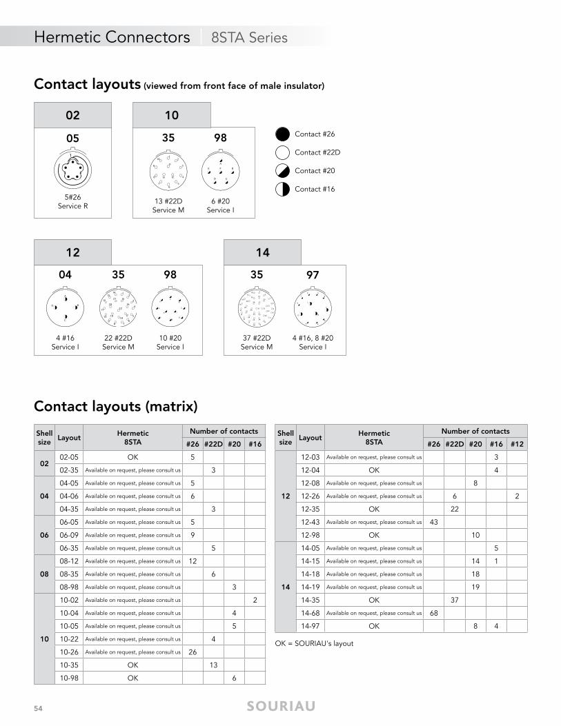
Contact layouts (matrix)
OK = SOURIAU's layout
Shellsize
LayoutHermetic
8STANumber of contacts
#26 #22D #20 #16
0202-05 OK 5
02-35 Available on request, please consult us 3
04
04-05 Available on request, please consult us 5
04-06 Available on request, please consult us 6
04-35 Available on request, please consult us 3
06
06-05 Available on request, please consult us 5
06-09 Available on request, please consult us 9
06-35 Available on request, please consult us 5
08
08-12 Available on request, please consult us 12
08-35 Available on request, please consult us 6
08-98 Available on request, please consult us 3
10
10-02 Available on request, please consult us 2
10-04 Available on request, please consult us 4
10-05 Available on request, please consult us 5
10-22 Available on request, please consult us 4
10-26 Available on request, please consult us 26
10-35 OK 13
10-98 OK 6
Shellsize
LayoutHermetic
8STANumber of contacts
#26 #22D #20 #16 #12
12
12-03 Available on request, please consult us 3
12-04 OK 4
12-08 Available on request, please consult us 8
12-26 Available on request, please consult us 6 2
12-35 OK 22
12-43 Available on request, please consult us 43
12-98 OK 10
14
14-05 Available on request, please consult us 5
14-15 Available on request, please consult us 14 1
14-18 Available on request, please consult us 18
14-19 Available on request, please consult us 19
14-35 OK 37
14-68 Available on request, please consult us 68
14-97 OK 8 4
Contact layouts (viewed from front face of male insulator)
98
6 #20Service I
35
13 #22DService M
10
04
4 #16Service I
98
10 #20Service I
35
22 #22DService M
12
97
4 #16, 8 #20Service I
35
37 #22DService M
14
02
05
5#26Service R
Contact #26
Contact #22D
Contact #20
Contact #16
55
Hermetic Connectors | 8STA Series
1+0.10.
PCB layout
Ø2.9153°
Ø10
Ø 7
.2 /
7.0
5.8±
0.05
Ø0.
5±0.
25
Ø8.
3±0.
2
2.5/3.3
1.65/1.752.5/2.6
14.2 max.
Color band
1.38
1.38
0.85
0.851.45
0.45
1.18
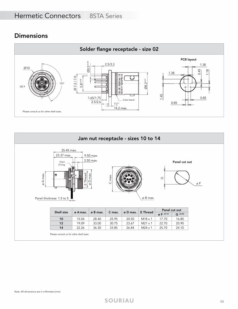
Solder fl ange receptacle - size 02
Please consult us for other shell sizes.
Note: All dimensions are in millimeters (mm)
Dimensions
Panel thickness: 1.5 to 5
35.45 max.
23.37 max. 9.50 max.
ø A
max
.
ø D
Viton O’ring
ø B max.
Panel cut out3.50 max.
ø D
max
.E
Thre
ad.
C m
ax.
G
ø F
Shell size ø A max. ø B max. C max. ø D max. E ThreadPanel cut out
ø F ±0.10 G ±0.20
10 15.04 28.40 25.95 20.50 M18 x 1 17.70 16.8012 19.09 33.00 30.75 23.67 M21 x 1 22.70 20.9014 22.26 36.30 33.85 26.84 M24 x 1 25.70 24.10
Jam nut receptacle - sizes 10 to 14
Please consult us for other shell sizes.
56
Hermetic Connectors | D-Sub Series
Mechanical
• Shell: Steel
• Shell plating: Cadmium, gold, bright tin lead, mat RoHS tin
• Contact: Ferrous alloy
• Contact plating: Gold, mat tin
• Endurance: 500 mating/unmating operations
Electrical
• Contact rating: 5A max
• Test voltage: 750 Vrms (max Vrms/50Hz)
• Insultaion resistance: ≥ 5000 MΩ
• Contact resistance: ≤ 14 mΩ
Environmental
• Operating temperature: -55°C to 125°C
• Hermeticity: Leak rate < 1.04.10-5 atm.cm3/s (helium gas test)
• Salt spray: 48 hours (cadmium) 24 hours (tin)
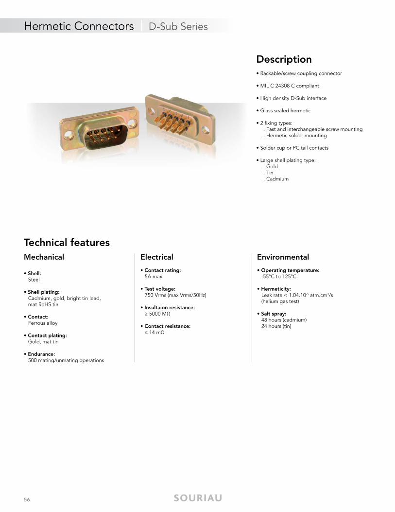
Description• Rackable/screw coupling connector
• MIL C 24308 C compliant
• High density D-Sub interface
• Glass sealed hermetic
• 2 fi xing types: . Fast and interchangeable screw mounting . Hermetic solder mounting • Solder cup or PC tail contacts
• Large shell plating type: . Gold . Tin . Cadmium
Technical features
57
Ordering information
Basic Series D E H 09 P 002
Shell size: E, A, B, C, DClass: H: HermeticNumber of contacts: 09 (E), 15 (A), 25 (B), 37 (C), 50 (D)Contact type: P: PinSpecifi cation:
Hermetic Connectors | D-Sub Series
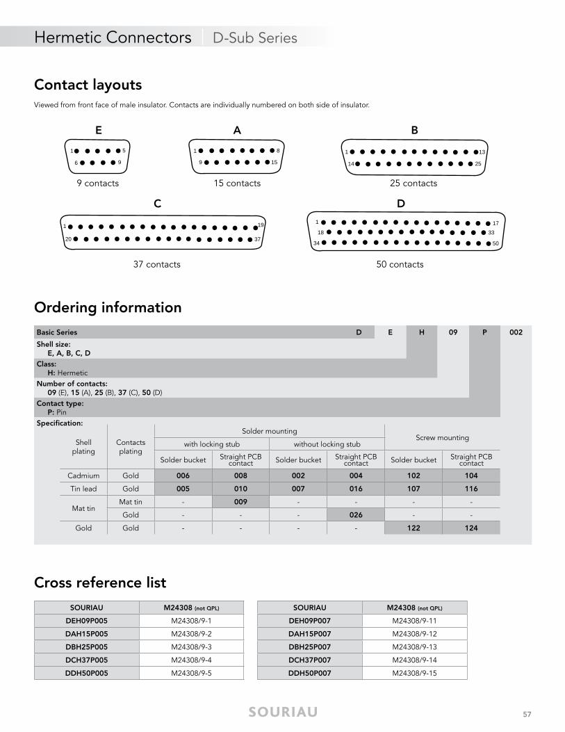
Contact layoutsViewed from front face of male insulator. Contacts are individually numbered on both side of insulator.
1 5
6 9
8
15
1
9
1 13
2514
1 19
3720
1
18
34
17
33
50
A BE
9 contacts 15 contacts 25 contacts
C D
50 contacts37 contacts
Shellplating
Contactsplating
Solder mountingScrew mounting
with locking stub without locking stub
Solder bucket Straight PCB contact Solder bucket Straight PCB
contact Solder bucket Straight PCB contact
Cadmium Gold 006 008 002 004 102 104
Tin lead Gold 005 010 007 016 107 116
Mat tinMat tin - 009 - - - -
Gold - - - 026 - -
Gold Gold - - - - 122 124
Cross reference list
SOURIAU M24308 (not QPL)
DEH09P005 M24308/9-1
DAH15P005 M24308/9-2
DBH25P005 M24308/9-3
DCH37P005 M24308/9-4
DDH50P005 M24308/9-5
SOURIAU M24308 (not QPL)
DEH09P007 M24308/9-11
DAH15P007 M24308/9-12
DBH25P007 M24308/9-13
DCH37P007 M24308/9-14
DDH50P007 M24308/9-15
58
Hermetic Connectors | D-Sub Series
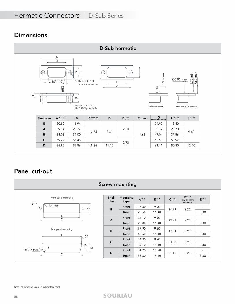
Note: All dimensions are in millimeters (mm)
Dimensions
Panel cut-out
AB
D C10°10°
E
F
J
HG
Hole Ø3.20for screw mounting
Locking stud 4.40 UNC 2B Tapped hole
Ø0.83 max
7.60
max
5.75
min
Solder bucket Straight PCB contact
6.95
max
AC
B
R: 0.8 max
A
C
E B
ØD
10°
Front panel mounting
Rear panel mounting
D
1.4 max
Shell size A 0/+0.30 B C 0/+0.30 D E +0.10 F max Gscrew mounting H ±0.20 J ±0.20
E 30.80 16.94
12.54 8.412.50
8.65
24.99 18.40
9.40A 39.14 25.27 33.32 23.70
B 53.03 39.00 47.04 37.56
C 69.29 55.452.70
63.50 53.97
D 66.92 52.86 15.36 11.10 61.11 50.80 12.70
-0.20
Shellsize
Mountingtype
A±0.1 B±0.1 C±0.1D±0.05
only for screw mounting
E±0.1
EFront 18.80 9.90
24.99 3.20-
Rear 20.50 11.40 3.30
AFront 24.10 9.90
33.32 3.20-
Rear 28.80 11.40 3.30
BFront 37.90 9.90
47.04 3.20-
Rear 42.50 11.40 3.30
CFront 54.30 9.90
63.50 3.20-
Rear 59.10 11.40 3.30
DFront 51.20 13.20
61.11 3.20-
Rear 56.30 14.10 3.30
D-Sub hermetic
Screw mounting
59
Hermetic Connectors | D-Sub Series
Note: All dimensions are in millimeters (mm)
Accessories
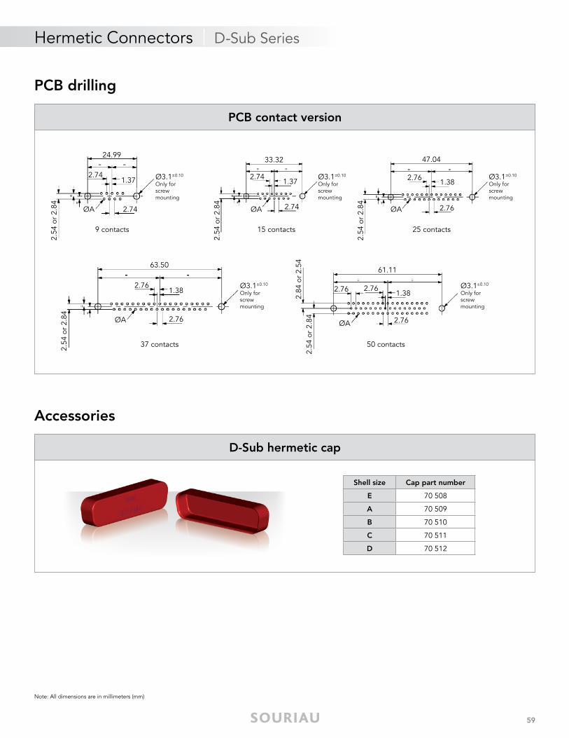
PCB drilling
Shell size Cap part number
E 70 508
A 70 509
B 70 510
C 70 511
D 70 512
ØA
Ø3.1±0.10
Only for screw mounting
2.74
1.372.74
24.99
2.54
or
2.84 ØA
Ø3.1±0.10
Only for screw mounting
2.74
1.372.74
33.32
2.54
or
2.84 ØA
Ø3.1±0.10
Only for screw mounting
2.76
1.382.76
47.04
2.54
or
2.84
ØA 2.76
1.382.76
63.50
2.54
or
2.84
ØA 2.76
1.382.76
61.11
2.54
or
2.84
2.84
or
2.54
2.76
9 contacts 15 contacts 25 contacts
50 contacts37 contacts
Ø3.1±0.10
Only for screw mounting
Ø3.1±0.10
Only for screw mounting
D-Sub hermetic cap
PCB contact version

HE
RM
ET
IC
© 2017 SOURIAU - SOURIAU is a registered trademark
Range ExtensionHermetic
Standard glass to metal sealing technologies:
Removable crimp contacts ............................................................................ 62 Hermetic receptacles with stand-offs ............................................................ 62 8LT27 rack & panel hermetic connector ....................................................... 63 Panel bulkhead .............................................................................................. 63 Hermetic compact connector metallized ...................................................... 64 Solder contacts on both sides of bulkhead ................................................... 64 Contact grounded on the shell ..................................................................... 65 Thermocouple ............................................................................................... 65
Alternative sealing technologies:
Resin sealed connector ................................................................................ 66
62
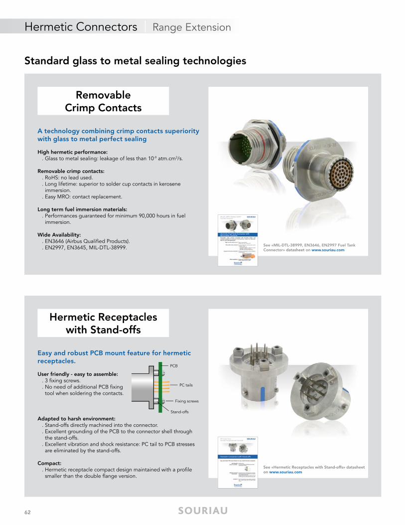
RemovableRemovableCrimp ContactsCrimp Contacts
A technology combining crimp contacts superiority with glass to metal perfect sealing
High hermetic performance: . Glass to metal sealing: leakage of less than 10-9 atm.cm3/s.
Removable crimp contacts: . RoHS: no lead used. . Long lifetime: superior to solder cup contacts in kerosene immersion. . Easy MRO: contact replacement.
Long term fuel immersion materials: . Performances guaranteed for minimum 90,000 hours in fuel immersion.
Wide Availability: . EN3646 (Airbus Qualified Products). . EN2997, EN3645, MIL-DTL-38999. See «MIL-DTL-38999, EN3646, EN2997 Fuel Tank
Connector» datasheet on www.souriau.com
Hermetic ReceptaclesHermetic Receptacleswith Stand-offswith Stand-offs
PCB
PC tails
Stand-offs
Fixing screws
Easy and robust PCB mount feature for hermetic receptacles.
User friendly - easy to assemble: . 3 fixing screws. . No need of additional PCB fixing tool when soldering the contacts.
Adapted to harsh environment: . Stand-offs directly machined into the connector. . Excellent grounding of the PCB to the connector shell through the stand-offs. . Excellent vibration and shock resistance: PC tail to PCB stresses are eliminated by the stand-offs.
Compact: . Hermetic receptacle compact design maintained with a profile smaller than the double flange version.
Standard glass to metal sealing technologies
Hermetic Connectors | Range Extension
See «Hermetic Receptacles with Stand-offs» datasheet on www.souriau.com
63
Hermetic Connectors | Range Extension
See «8LT27 Series - Hermetic Connectors» datasheet on www.souriau.com
Standard glass to metal sealing technologies
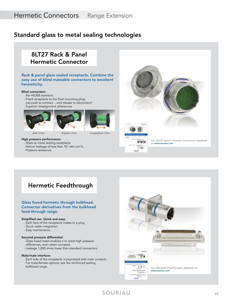
8LT27 Rack & Panel8LT27 Rack & PanelHermetic ConnectorHermetic Connector
Rack & panel glass sealed receptacle. Combine the easy use of blind mateable connectors to excellent hermeticity.
Blind connection: . Per HE308 standard. . Fixed receptacle to the float mounting plug: just push to connect... and release to disconnect! . Superior misalignment allowances:
High pressure performance: . Glass to metal sealing receptacle . Helium leakage of less than 10-7 atm.cm3/s. . Pressure resistance.
Hermetic FeedthroughHermetic Feedthrough
Glass fused hermetic through bulkhead.Connector derivatives from the bulkheadfeed-through range.
Simplified use. Quick and easy: . Each face of the receptacle mates to a plug. . Quick cable integration. . Easy maintenance.
Secured pressure differential: . Glass fused insert enables it to resist high pressure differences, even when unmated. . Leakage 1,000 times lower than standard connectors.
Male/male interface: . Each side of the receptacle is populated with male contacts. . For male/female options, see the reinforced sealing bulkhead range.
Axial ±1mm Angular ±1mm Longitudinal ±1mm
See «Hermetic Feed-through» datasheet on www.souriau.com
64
Hermetic Connectors | Range Extension
See «AM89 Receptacle - Hermetic Connectors» datasheet on www.souriau.com
Standard glass to metal sealing technologies
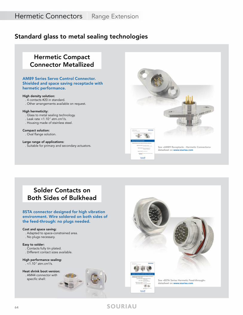
Hermetic Compact Hermetic Compact Connector MetallizedConnector Metallized
AM89 Series Servo Control Connector.Shielded and space saving receptacle withhermetic performance.
High density solution: . 4 contacts #20 in standard. . Other arrangements available on request.
High hermeticity: . Glass to metal sealing technology. . Leak rate <1.10-7 atm.cm3/s. . Housing made of stainless steel.
Compact solution: . Oval flange solution.
Large range of applications: . Suitable for primary and secondary actuators.
Solder Contacts onSolder Contacts onBoth Sides of BulkheadBoth Sides of Bulkhead
8STA connector designed for high vibrationenvironment. Wire soldered on both sides ofthe feed-through: no plugs needed.
Cost and space saving: . Adapted to space-constrained area. . No plugs necessary.
Easy to solder: . Contacts fully tin plated. . Different contact sizes available.
High performance sealing: . <1.10-7 atm.cm3/s.
Heat shrink boot version: . AM44 connector with specific shell: See «8STA Series Hermetic Feed-through»
datasheet on www.souriau.com
on: h
65
Hermetic Connectors | Range Extension
Standard glass to metal sealing technologies
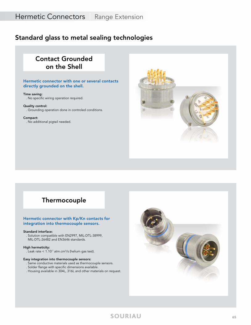
Hermetic connector with one or several contacts directly grounded on the shell.
Time saving: . No specific wiring operation required.
Quality control: . Grounding operation done in controled conditions.
Compact: . No additional pigtail needed.
Contact GroundedContact Groundedon the Shellon the Shell
ThermocoupleThermocouple
Hermetic connector with Kp/Kn contacts forintegration into thermocouple sensors.
Standard interface: . Solution compatible with EN2997, MIL-DTL-38999, MIL-DTL-26482 and EN3646 standards.
High hermeticity: . Leak rate < 1.10-7 atm.cm3/s (helium gas test).
Easy integration into thermocouple sensors: . Same conductive materials used as thermocouple sensors. . Solder flange with specific dimensions available. . Housing available in 304L, 316L and other materials on request.
66
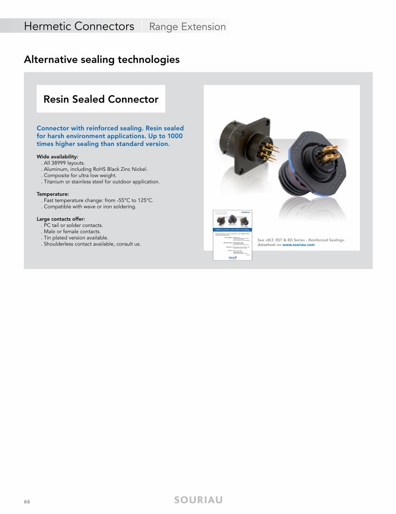
Resin Sealed ConnectorResin Sealed Connector
Connector with reinforced sealing. Resin sealed for harsh environment applications. Up to 1000 times higher sealing than standard version.
Wide availability: . All 38999 layouts. . Aluminum, including RoHS Black Zinc Nickel. . Composite for ultra low weight. . Titanium or stainless steel for outdoor application.
Temperature: . Fast temperature change: from -55°C to 125°C. . Compatible with wave or iron soldering.
Large contacts offer: . PC tail or solder contacts. . Male or female contacts. . Tin plated version available. . Shoulderless contact available, consult us.
Alternative sealing technologies
See «8LT, 8ST & 8D Series - Reinforced Sealing» datasheet on www.souriau.com
Hermetic Connectors | Range Extension


Your local contact
Our contribution to environmental protection:This catalog is printed on PEFC certifi ed paperAdvancement of sustainablewood cultivation. www.pefc.org
WC
AH
ERM
WU
SEN
11 ©
Cop
yrig
ht S
OU
RIA
U A
pr
2017
- S
OU
RIA
U is
a re
gis
tere
d t
rad
emar
k A
ll in
form
atio
n in
thi
s d
ocum
ent
pre
sent
s on
ly g
ener
al p
artic
ular
s an
d s
hall
not
form
par
t of
any
con
trac
t. A
ll rig
hts
rese
rved
to
SOU
RIA
U fo
r ch
ang
es w
ithou
t p
rior
notifi
cat
ion
or p
ublic
ann
ounc
emen
t. A
ny d
uplic
atio
n is
pro
hib
ited
, unl
ess
app
rove
d in
writ
ing
.
10-31-1299
Reliable People, Reliable Solutions
www.esterline-connection-technologies.comtechnical-emear-ect@esterline.com (Europe - Asia - Africa)
[email protected] (North America)


