Heterogeneous Modeling: Hybrid Systems Heterogeneous Modeling: Hybrid Systems Hybrid Models Automotive Powertrain Languages and Verification Problems Simulink and StateFlow CheckMate Charon Masaccio
Transcript
Heterogeneous Modeling: Hybrid SystemsHeterogeneous Modeling: Hybrid Systems
Hybrid ModelsAutomotive Powertrain
Languages and Verification ProblemsSimulink and StateFlowCheckMateCharonMasaccio
MotivationMotivation
Hybrid Systems are becoming a major modeling paradigm for embedded systems
Capability of modeling controller and plantUse of concurrent multiple levels of abstraction
Difficult to verify and designCombination of continuous and discrete dynamics of different typesLack of “operationally strong” theoretical results
Variety of tools and approaches mutually incompatible due to modeling differences
Foundations of Hybrid ModelFoundations of Hybrid Model
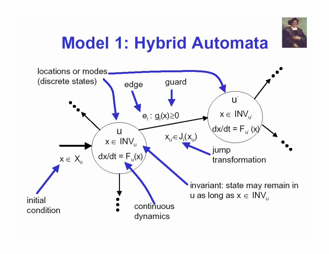
Used classic model by J. Lygeros, S. Sastry and C. Tomlin as basis
Model consists of three parts:Structure= sets, discrete and dynamical componentsTime Bases= intervals over which behavior is continuousHybrid execution= rules according to which we have jumps and continuous flows
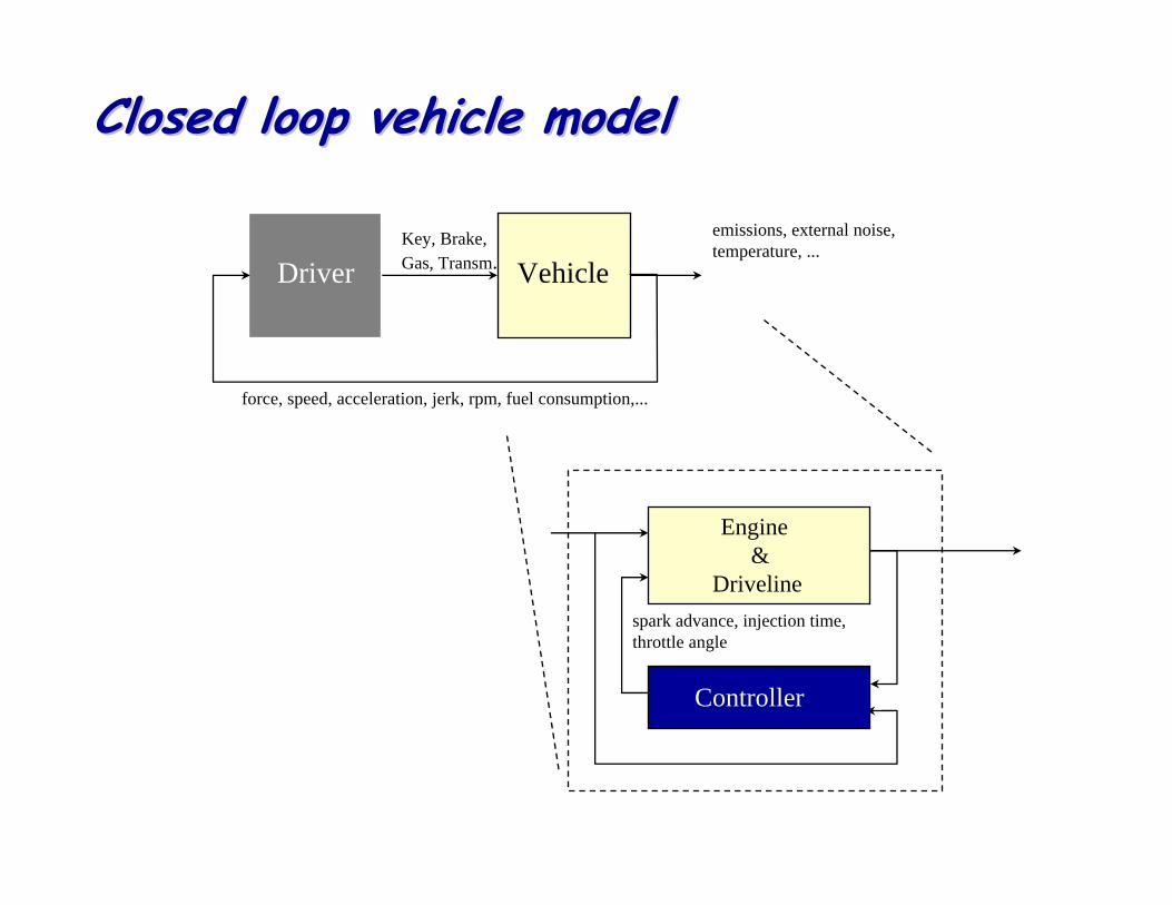
Closed loop vehicle modelClosed loop vehicle model
Fa st N e ga tiveFor ce Tr a ns ien t
m in f(D , M fue l)τ < τ m ax
For ce T r a ck ing
Fa st P osi tiveFor ce Tr a ns ien t
S pe e d Tr ack in g
n= n(.) n= n(.)
I dle & T r a sm On
.G > 0 | t >τ
. .G < G B| B = 1
.G < 0 | t >τ
. .G > G A
G > 0
G = 0
T > 0
T =0 T =0
(G > 0 )& (T> 0 )
T =0
fI( n) = 0 & G = 0
fI( n ,G ) > 0
.G = 0 & C= 1
.G > 0| B = 1
T > 0
T =0
O U T PUT :
n - E ng ine S p eedn - E ng ine S p eedFFG G - Gen erated Fo rceVV GG - Veh icle S p eed - Veh icle S p eed
n= n(G )F G = 0
R pm Tr ackingn= ar gm in(M fu el)
Id le
F G = 0
V G = V G (.)
S topn= 0
F G = 0
S tar tu p
F G = 0n= .
G > 0G = 0
(n < n m in)| (K = Of f) n > n st art up
K = St ar t
(n < n m in)| (K = O ff)
F G = F G(G ,T ,n)F G = F G(G ,T ,n)
m ax Dτ < τ m ax
m in τ
F G = F G(G ,T ,n)
M fue l < M m a x; D >D m in
T >0 &G = 0
IN P UT S:
G - G as P edalG - G as P edalT - C lu tc h Ped al & Gear S tickT - C lu tc h Ped al & Gear S tickB - Brak e P ed alB - Brak e P ed alC - C ru ise C o n tro lC - C ru ise C o n tro l
K - Key
D - C o m fort
fI( n) = 0 & G = 0
Why Mixed Models of Computation Why Mixed Models of Computation in internal combustion engines control ?in internal combustion engines control ?
Specifications
Control variables
Physical processes in the plant
Description of the HW/SW implementation constraints
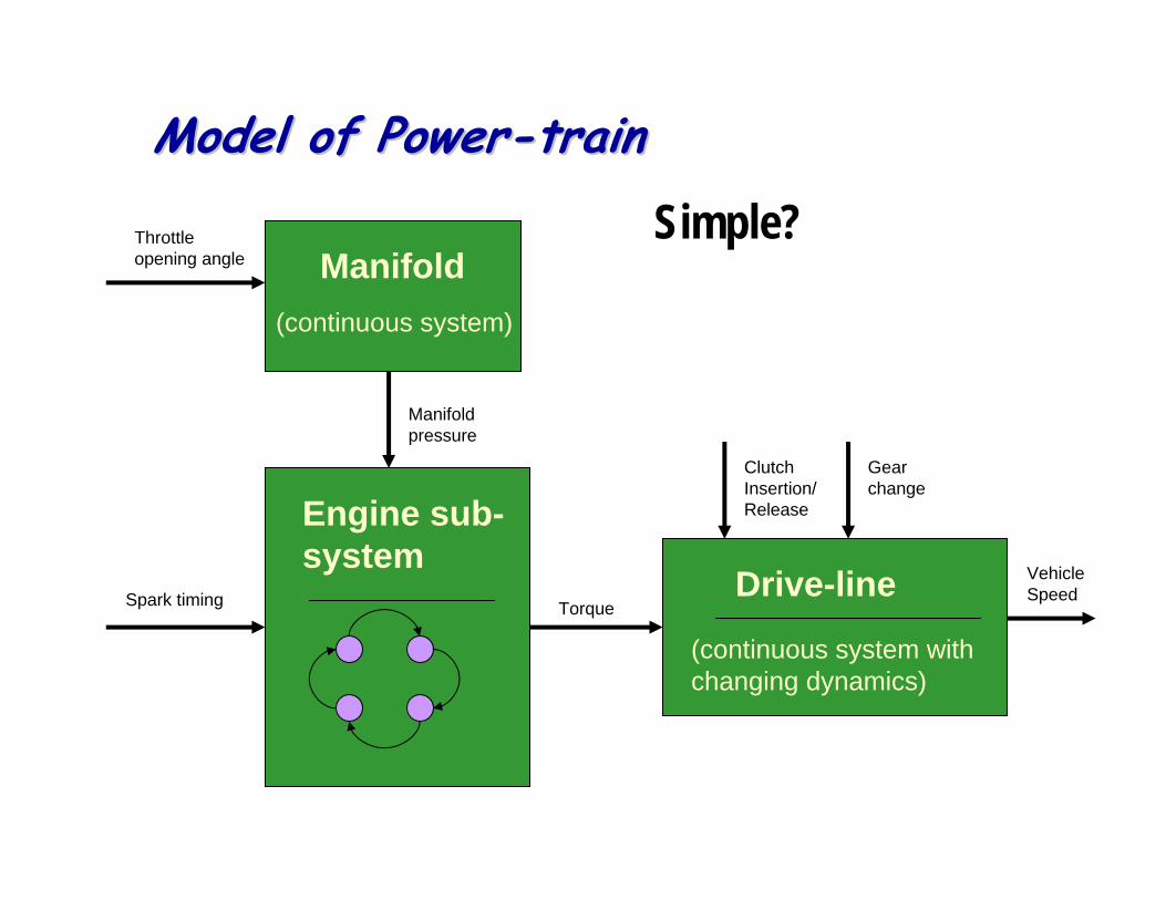
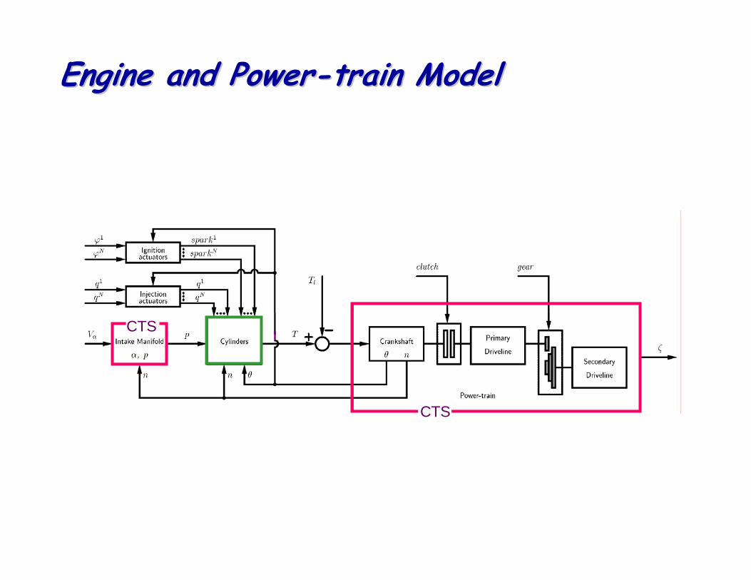
Engine and PowerEngine and Power--train Modeltrain Model
CTS
CTS
Intake ManifoldIntake Manifold
V(t) - throttle motor voltage α (t) - throttle angle
n (t) - crankshaft speed p (t) - manifold pressure
V(t)
α (t)motor dynamics
p (t)
air dynamics
n (t)
aV(t)
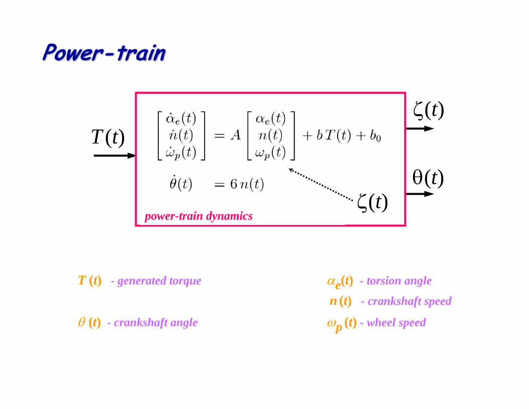
PowerPower--traintrain
T (t) - generated torque αe(t) - torsion angle
n (t) - crankshaft speed
θ (t) - crankshaft angle ωp (t) - wheel speed
T (t)
power-train dynamicsζ(t)
ζ(t)
θ(t)
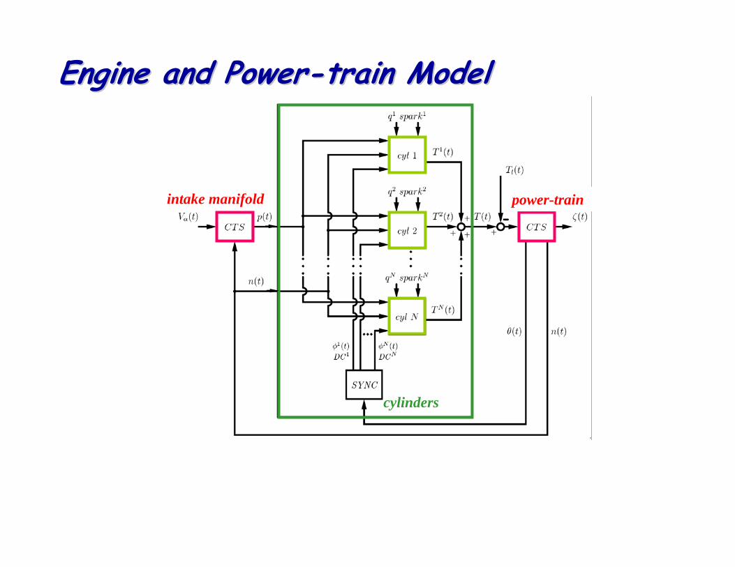
Engine and PowerEngine and Power--train Modeltrain Model
cylinders
intake manifold power-train
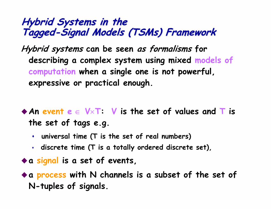
Hybrid Systems in the Hybrid Systems in the TaggedTagged--Signal Models (Signal Models (TSMsTSMs) Framework) FrameworkHybrid systems can be seen as formalisms for
describing a complex system using mixed models of computation when a single one is not powerful, expressive or practical enough.
An event e ∈ V×T: V is the set of values and T is the set of tags e.g.
universal time (T is the set of real numbers)discrete time (T is a totally ordered discrete set),
a signal is a set of events,a process with N channels is a subset of the set of N-tuples of signals.
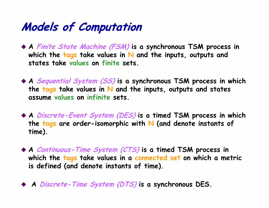
Models of ComputationModels of ComputationA Finite State Machine (FSM) is a synchronous TSM process in which the tags take values in N and the inputs, outputs and states take values on finite sets.
A Sequential System (SS) is a synchronous TSM process in which the tags take values in N and the inputs, outputs and states assume values on infinite sets.
A Discrete-Event System (DES) is a timed TSM process in which the tags are order-isomorphic with N (and denote instants of time).
A Continuous-Time System (CTS) is a timed TSM process in which the tags take values in a connected set on which a metric is defined (and denote instants of time).
A Discrete-Time System (DTS) is a synchronous DES.
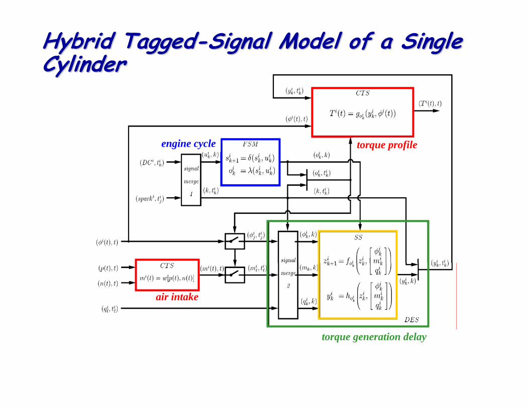
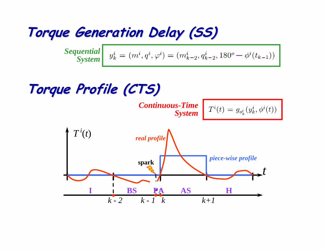
Hybrid TaggedHybrid Tagged--Signal Model of a Single Signal Model of a Single CylinderCylinder
engine cycle torque profile
torque generation delay
air intake
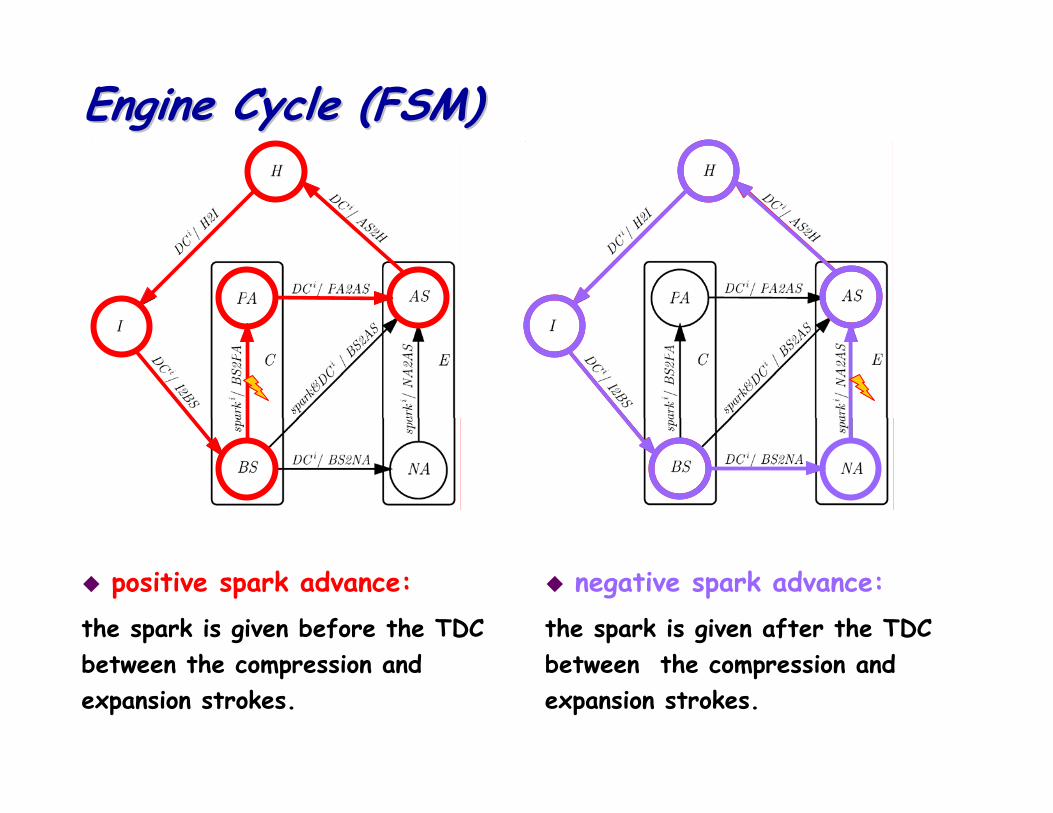
Engine Cycle (FSM)Engine Cycle (FSM)
positive spark advance:the spark is given before the TDC between the compression and expansion strokes.
negative spark advance:the spark is given after the TDC between the compression and expansion strokes.
Engine and PowerEngine and Power--train Modeltrain Model
cylinders
intake manifold power-train
Mean-Value Model: accurate over a longer time window
regulation control problemslow performance transient problems
Hybrid Model: cycle accuratetransient control problems stability of delay-sensitive control algorithmshigh performance control algorithms
Hybrid Model vs MeanHybrid Model vs Mean--Value ModelValue Model
OutlineOutline
Hybrid Models
Languages and Verification ProblemsSimulink and StateFlowCheckMateCharonMasaccio
What is a simulator?What is a simulator?Given a mathematical model of the system, computes its evolutionand its outputs under a pre-determined set of inputs
The mathematical model expresses heterogeneity and concurrency
The simulator computes the response of the model by mapping it onto the “device” used to carry out the computation
In general, the computing device has limited resources and is digital
We must embed the model of time of the model into the model of the computing device that gives the “common denominator” (e.g., discretize time, synchronize)We must map a set of concurrent processes into a sequential system (e.g., schedule execution of concurrent processes)
Hybrid Systems SimulationHybrid Systems Simulation
FSM,Discrete Eventand other MOCs
Continuous Time
• Integrator (hold)
Interface
Inputs Outputs
t
t
• Invariants & Guards• Sampling
Hybrid System SimulationHybrid System Simulation
A simulator for hybrid systems must capture different types of behaviors:
Continuos TimeDiscrete Events FSMs …
and resolve the domain interface problems.
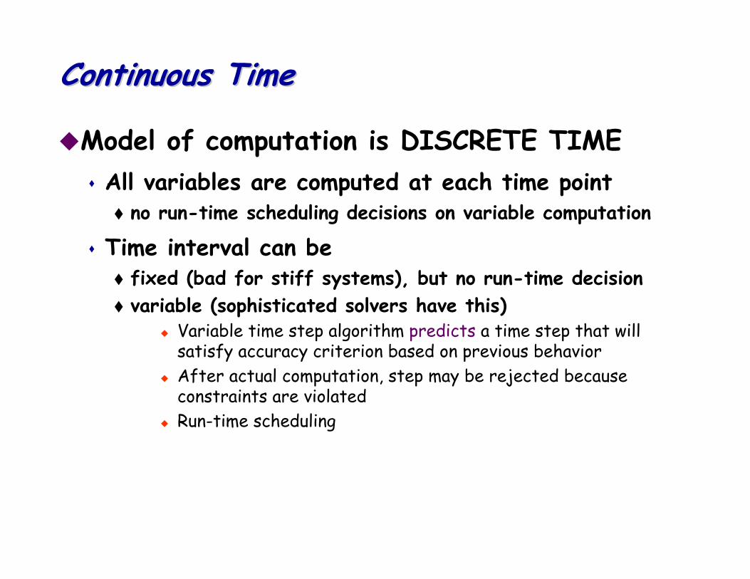
Continuous TimeContinuous Time
Model of computation is DISCRETE TIMEAll variables are computed at each time point
no run-time scheduling decisions on variable computation
Time interval can be fixed (bad for stiff systems), but no run-time decision variable (sophisticated solvers have this)
Variable time step algorithm predicts a time step that will satisfy accuracy criterion based on previous behaviorAfter actual computation, step may be rejected because constraints are violatedRun-time scheduling
Discrete DomainDiscrete Domain
Two basic techniques:Zero-time assumption:
Static scheduling of computationCan be done off-line for maximum efficiency (cycle-based simulation)
Components modeled with delay (Discrete Event Model).
All components evaluated at the same time-point always (wasteful)Follow reaction to events: schedule components whose inputs have changed (assumes internal dynamics completely captured by pure delay) Selective-trace event-driven simulation.
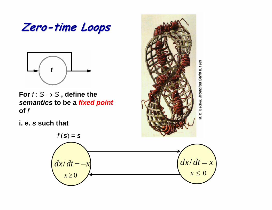
ZeroZero--time Loopstime Loops
xdtdx −=/ xdtdx =/0≤x0≥x
For f : S → S , define the semantics to be a fixed point of f
i. e. s such that
f (s) = s
Synchronization ProblemSynchronization Problem
“Synchronization” between domains: sample the continuous time interface variablesintegrate discrete event interface signalsdetect guards and invariants (zero crossing detection)
Simulator ArchitectureSimulator Architecture
One simulator (e.g. Ptolemy)different algorithms for each domain and unique scheduler
N simulators (e.g. Simulink-StateFlow, Simulink-Bones, Simulink-VCC)
One simulator per domain (different schedulers per domain) and communication among simulators. Scheduler works by transferring control to simulatorMuch less efficient but easier to do!
Invariant DetectionInvariant Detection
An approach: the discrete event simulator checks the conditions sampling the continuos time variables
Advantages:easiest implementationstrong separation between the two domains
Drawbacks:high precision detection reached only with long simulation time.high inter-process communication overhead
Partial Solution:Simulation look-ahead
OutlineOutline
Introduction to WP
Hybrid Models
Languages and Verification ProblemsSimulink and StateFlowCheckMateCharonMasaccio
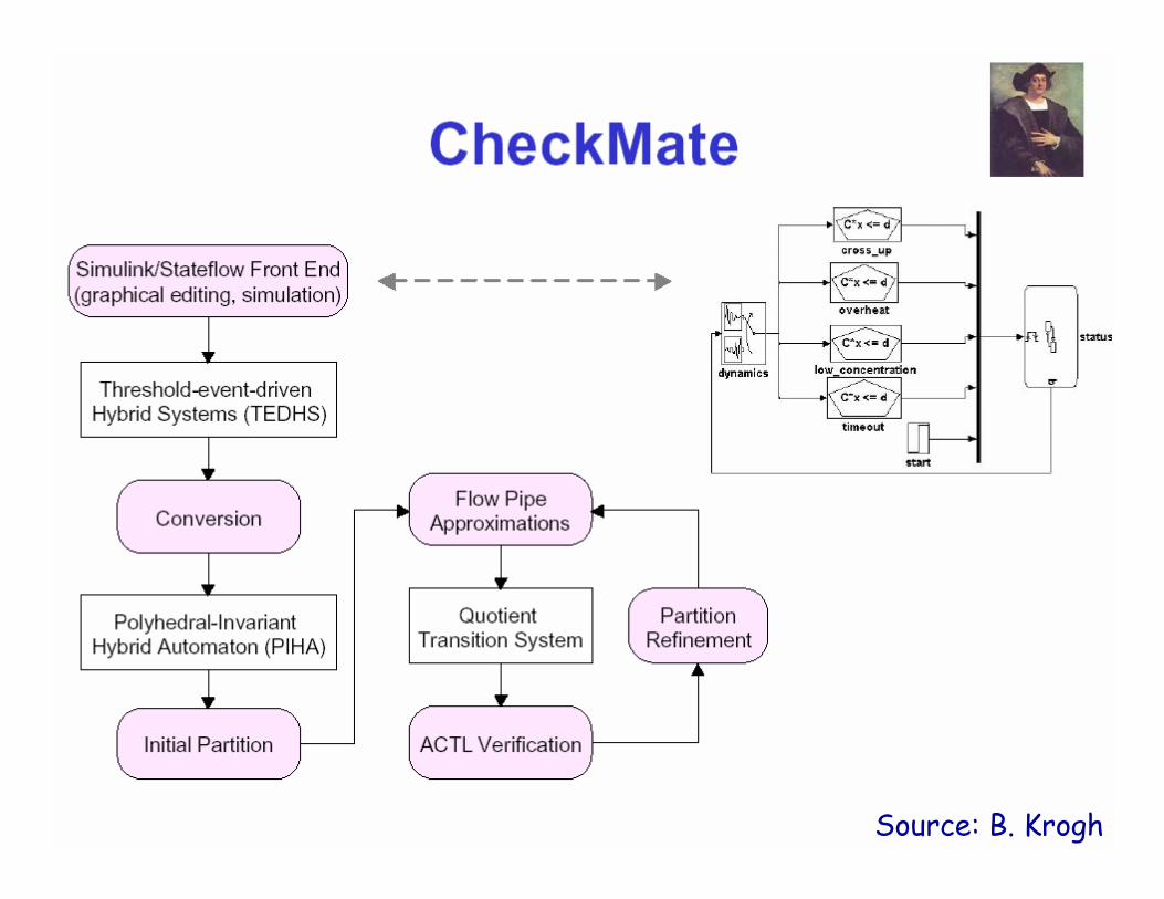
Source: B. Krogh
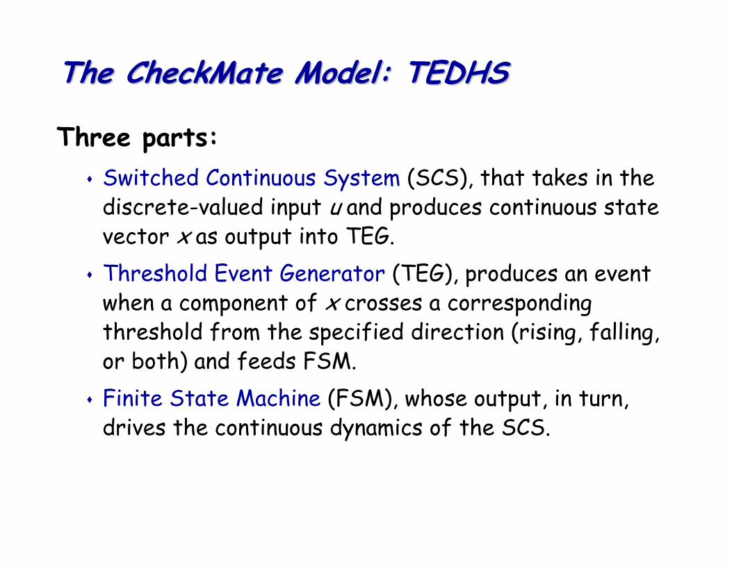
The The CheckMateCheckMate Model: TEDHSModel: TEDHS
Three parts:Switched Continuous System (SCS), that takes in the discrete-valued input u and produces continuous state vector x as output into TEG.Threshold Event Generator (TEG), produces an event when a component of x crosses a corresponding threshold from the specified direction (rising, falling, or both) and feeds FSM.Finite State Machine (FSM), whose output, in turn, drives the continuous dynamics of the SCS.
Source: B. Krogh
Source: B. Krogh
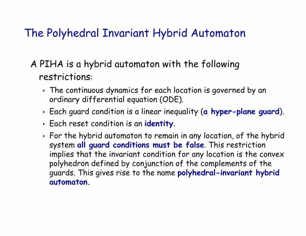
The Polyhedral Invariant Hybrid Automaton
A PIHA is a hybrid automaton with the following restrictions:
The continuous dynamics for each location is governed by an ordinary differential equation (ODE).Each guard condition is a linear inequality (a hyper-plane guard).Each reset condition is an identity.For the hybrid automaton to remain in any location, of the hybrid system all guard conditions must be false. This restriction implies that the invariant condition for any location is the convex polyhedron defined by conjunction of the complements of the guards. This gives rise to the name polyhedral-invariant hybrid automaton.
CheckMateCheckMate SummarySummary
Integrated with Matlab/Simulink/StateFlowLimited semantics to simplify analysis and allow formal verificationUses Simulink constructs to enter dataBased on reachability analysis to abstract continuous awayCan perform simulation, partial and complete verificationComputationally complex…
OutlineOutline
Hybrid Models
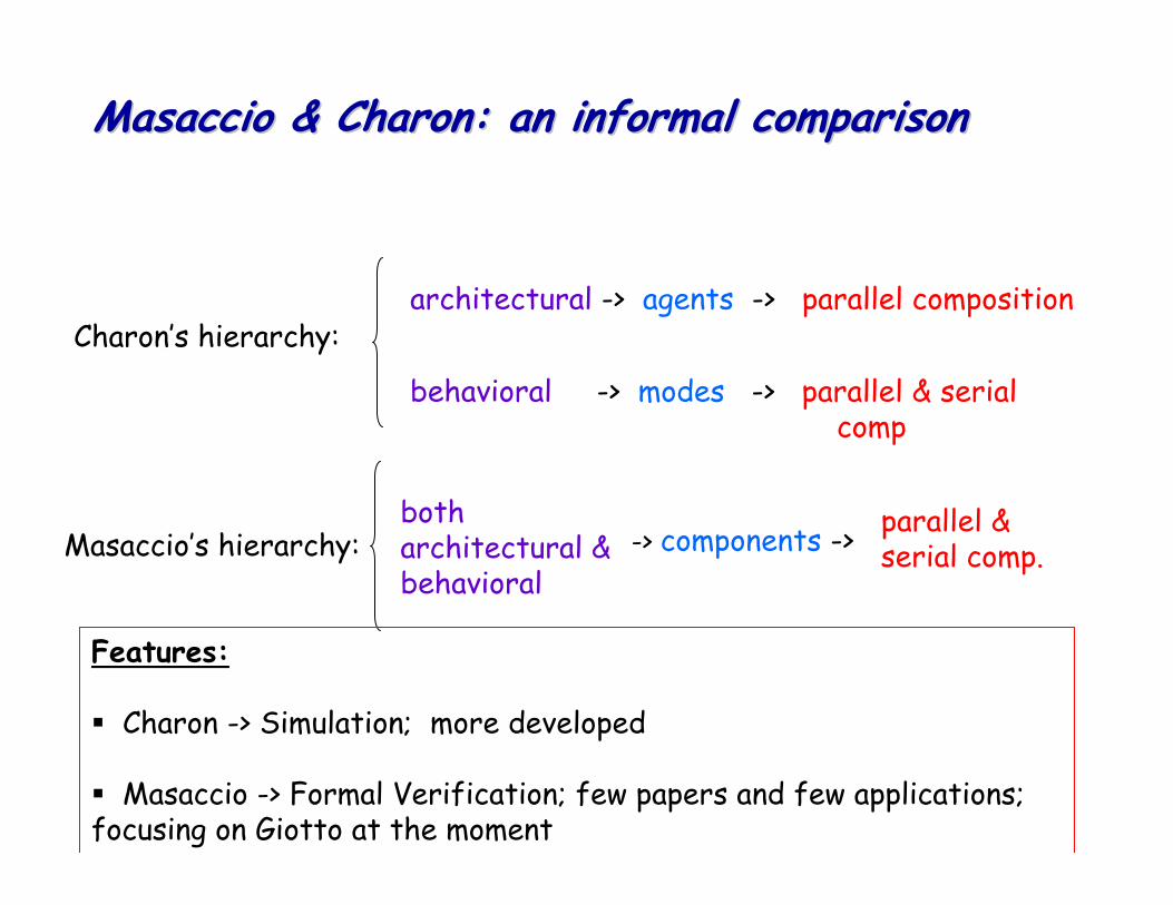
Languages and Verification ProblemsSimulink and StateFlowCheckMateCharonMasaccio
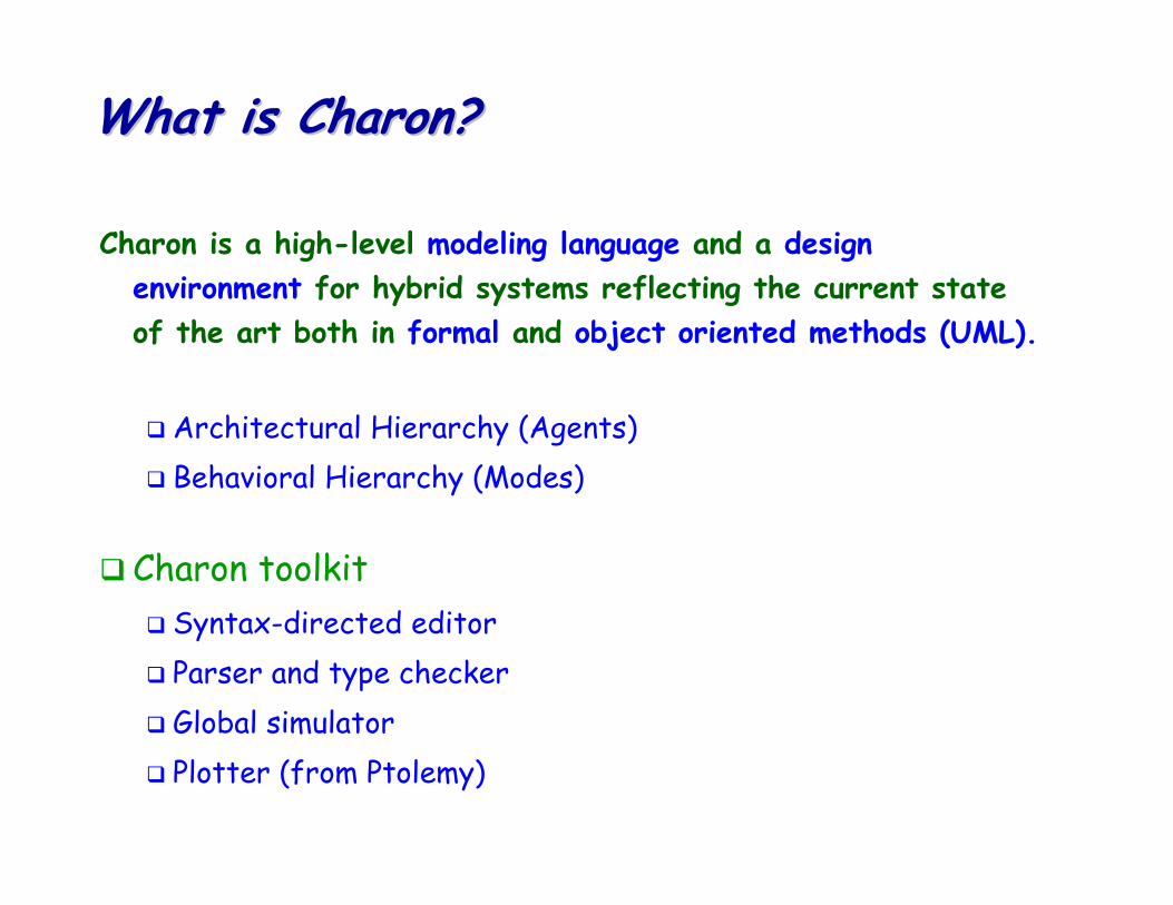
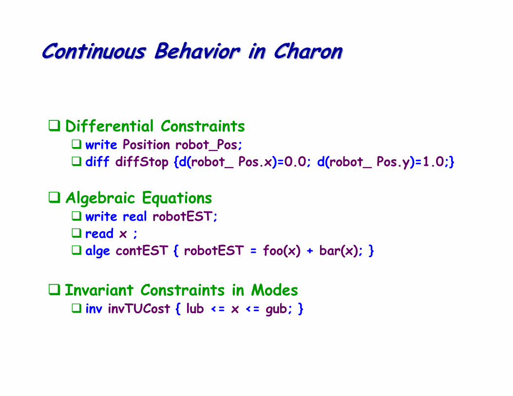
Charon is a high-level modeling language and a design environment for hybrid systems reflecting the current state of the art both in formal and object oriented methods (UML).