International Journal on Electrical Engineering and Informatics ‐ Volume 4, Number 1, March 2012 Heuristic Approach for Distribution Systems Feeder Reconfiguration to Line Maximum Loadability K. Nagaraju 1 , S. Sivanagaraju 2 , T. Ramana 3 , V. Ganesh 4 1 Department of Electrical & Electronics Engg, SSN Engineering College, Ongole, AP, India 2 Department of Electrical & Electronics Engg., University College of Engineering, JNTU, Kakinada,India 3 HP Global Soft Limited, Bangalore, Karnataka, India 4 Department of Electrical & Electronics Engg., University College of Engineering, JNTU, Pulivendula,India [email protected], [email protected], [email protected], [email protected]Abstract: This paper presents a heuristic approach for optimal feeder reconfiguration of radial distribution systems (RDS). Optimal feeder reconfiguration involves the selection of the best set of branches to be opened by considering the all tie switches, such that the resulting RDS has the desired performance. Amongst the several performance criteria considered for optimal feeder reconfiguration, line maximizing loadability is an important one. In this paper an algorithm is proposed based on simple heuristic rules and identified an effective switch status configuration of distribution system for maximizing the line maximum loadability of the system. The line maximum loadability, power loss and voltage profile calculation of the best switching combination are found by load flow solution. Compared to other published articles, the proposed method reduces the switching combinations searched and gives the optimum solution in few number of load flow runs. To demonstrate the validity of the proposed algorithm, computer simulations are carried out on 33-bus system and the performance of the proposed method compared with the other existing methods. Keywords: radial distribution networks, feeder reconfiguration, load flow, heuristic technique 1. Introduction Distribution networks generally operate in a radial configuration. Feeder reconfiguration is very important for operating the distribution system at minimum cost and to improve the system security. The reconfiguration of a distribution system is a process that alters feeder topological structure, changing the open/close status of sectionalizing switches and tie switches in the system. Large number of candidate switching combinations in the system and discrete nature of the switches, make the problem a formidable mixed integer nonlinear optimization problem. In the last two decades, considerable efforts have been made to solve this problem. Merlin and Back [1] proposed a branch and bound technique, in which all the network switches are closed first to form a meshed system and then the switches are opened successively to restore radial configuration. Shirmohammadi and Hong [2] proposed a technique in which the switches were opened one by one beginning from a fully meshed system, based on an optimal flow pattern. In [3, 4] a branch exchange method was used in which approximate formulae provide the change in loss due to feeder reconfiguration. Goswami and Basu [5] proposed an algorithm based on optimal flow pattern, of a single loop, formed by closing a normally open switch, and the switch with minimum current was opened. Taylor and Lubkeman [6] developed an expert system using heuristic rules to shrink the search space for reducing the computation time. Wagner et al. [7] proposed a linear programming method and a heuristic search method. Glaomocanin [8] used a quadratic programming technique to solve the reconfiguration problem. Borozan et al. [9] presented a method similar to that of [1, 2], for solving reconfiguration problem. Compensation-based power flow method was used to obtain power Received: June 16 th , 2011. Accepted: March 16 th , 2012 104
Transcript
International Journal on Electrical Engineering and Informatics ‐ Volume 4, Number 1, March 2012
Heuristic Approach for Distribution Systems Feeder Reconfiguration to Line Maximum Loadability
K. Nagaraju1, S. Sivanagaraju2, T. Ramana3, V. Ganesh4
1Department of Electrical & Electronics Engg, SSN Engineering College, Ongole, AP, India
2Department of Electrical & Electronics Engg., University College of Engineering, JNTU, Kakinada,India 3HP Global Soft Limited, Bangalore, Karnataka, India
4Department of Electrical & Electronics Engg., University College of Engineering, JNTU, Pulivendula,India
Abstract: This paper presents a heuristic approach for optimal feeder reconfiguration of radial distribution systems (RDS). Optimal feeder reconfiguration involves the selection of the best set of branches to be opened by considering the all tie switches, such that the resulting RDS has the desired performance. Amongst the several performance criteria considered for optimal feeder reconfiguration, line maximizing loadability is an important one. In this paper an algorithm is proposed based on simple heuristic rules and identified an effective switch status configuration of distribution system for maximizing the line maximum loadability of the system. The line maximum loadability, power loss and voltage profile calculation of the best switching combination are found by load flow solution. Compared to other published articles, the proposed method reduces the switching combinations searched and gives the optimum solution in few number of load flow runs. To demonstrate the validity of the proposed algorithm, computer simulations are carried out on 33-bus system and the performance of the proposed method compared with the other existing methods. Keywords: radial distribution networks, feeder reconfiguration, load flow, heuristic technique
1. Introduction Distribution networks generally operate in a radial configuration. Feeder reconfiguration is very important for operating the distribution system at minimum cost and to improve the system security. The reconfiguration of a distribution system is a process that alters feeder topological structure, changing the open/close status of sectionalizing switches and tie switches in the system. Large number of candidate switching combinations in the system and discrete nature of the switches, make the problem a formidable mixed integer nonlinear optimization problem. In the last two decades, considerable efforts have been made to solve this problem. Merlin and Back [1] proposed a branch and bound technique, in which all the network switches are closed first to form a meshed system and then the switches are opened successively to restore radial configuration. Shirmohammadi and Hong [2] proposed a technique in which the switches were opened one by one beginning from a fully meshed system, based on an optimal flow pattern. In [3, 4] a branch exchange method was used in which approximate formulae provide the change in loss due to feeder reconfiguration. Goswami and Basu [5] proposed an algorithm based on optimal flow pattern, of a single loop, formed by closing a normally open switch, and the switch with minimum current was opened. Taylor and Lubkeman [6] developed an expert system using heuristic rules to shrink the search space for reducing the computation time. Wagner et al. [7] proposed a linear programming method and a heuristic search method. Glaomocanin [8] used a quadratic programming technique to solve the reconfiguration problem. Borozan et al. [9] presented a method similar to that of [1, 2], for solving reconfiguration problem. Compensation-based power flow method was used to obtain power
Received: June 16th, 2011. Accepted: March 16th, 2012
104
flow solution for meshed system. A survey on reconfiguration was presented in [10]. Sarfi et al. [11] developed a method based on partitioning the distribution system into group of load buses, such that the line section losses between groups of nodes were minimized. Roytelman et al. [12] presented a heuristic-based two stage solution approach, in which weights were assigned to multi-objective functions. In [13, 14], algorithms for distribution system switch reconfiguration and capacitor control have been proposed. McDermott et al. [15] proposed a constructive heuristic method that started with all switches open, and at each step, the switch that resulted in the least increase in the objective function was closed. Lin and Chin [16] designed heuristic based switching indices, by utilizing fuzzy notations for the distribution system loss reduction. In [17] Broadwater presented a reconfiguration algorithm that calculates switching pattern as a function of time. Both manual and automatic switches are used to reconfigure the system for seasonal studies, whereas only automatic switches are considered for daily studies. Gomes et al. [18] presented an algorithm based on a heuristic strategy. The solution started with a meshed system obtained by closing all tie switches. Then the switches were opened successively based on minimum power loss increase, determined by a power flow. A branch exchange procedure was applied in the neighborhoods of the open switches to improve the solution. They presented an optimal power flow-based approach [19], in which the switch status was represented by continuous functions to reduce the number of power flows in [18]. Schmidt et al. [20] formulated the problem as mixed integer, nonlinear optimization problem. Newton method is used to compute branch currents within the integer search. Chen and Cho [21] presented an approach to derive optimal switching plan to achieve energy loss minimisation, for short- and long-term operation of distribution systems. Zhou et al. [22] proposed a heuristic approach for reconfiguration, which reduced operating cost over a specified time period. In [23], a method was proposed to determine the configuration with minimum energy loss for a given period. In [24–27], solution strategies have been proposed for feeder reconfiguration using simulated annealing. Morton et al. [28] developed graph–theoretic techniques involving semi-sparse transformations of a current sensitivity matrix. Das [29] presented a method based on heuristic rules and fuzzy multi-objective approach. In [30–35], different approaches were presented to obtain minimum loss configuration of the distribution system using genetic algorithm. Hsiao et al. [36] proposed a multi-objective evolutionary programming method, in which an interactive fuzzy algorithm has been used for obtaining a solution. Ramos et al. [37] developed algorithms based on genetic algorithm and conventional mixed integer linear problem. Mary and Babu [38] proposed a systematic methodology to derive the optimal switching criterion to reduce the energy loss for short and long terms operation of distribution systems. At present, new methods based on artificial intelligence have been used. Dolatdar et al. [39] proposed an approach of network reconfiguration based on a tree model using radial distribution power flow and genetic algorithm. Jen-Hao Teng [40] proposed a direct approach for distribution system load flow solutions. This approach has been integrated with graph theory to follow changes in system structure during reconfiguration. Srinivasa and Narasimham [41] developed an algorithm based on the voltage differences and power losses. Wang and Cheng [42] proposed an approach of network reconfiguration based on plant growth simulation algorithm. Vanderson et.al [43] proposed a heuristic reconfiguration algorithm for large distribution systems. This paper presents a simple line loadability index (LLI) that gives a measure of the proximity of the present state of a line in the RDS to maximum loadability. LLI gives an estimate of line loading margin as a factor of the existing load that may be draw before reaching the point of maximum loadability. The value of LLI may be computed at each line of the RDS. A value of LLI close to 1.0 indicates that the feeder would be unable to supply any more apparent power. Using the proposed index, the buses close to maximum loadability may be identified andvappropriate action for improvement may be initiated through an optimal reconfiguration scheme. The second part of the paper proposes a heuristic approach for optimal
K. Nagaraju, et al.
105
reconfiguutilizationoccurs ducapacity. lines. It cpower (VOptimal rRDS suchdeterminathat the rapproach.the differe
2. Math
(LLI) Consip and receload is PL
From Figu
pqI =
or pI
Equating The real p
p VV
and the im p VV
From eqn
qP =
uration of RDSn of capital invue to restrictedReconfigurati
changes the reaVAr) losses in reconfigurationh that the loadaation of a combresulting conf. The proposedent methods av
ematical Form der a typical beiving end bus
Lq+jQLq and the
Figure 1
ure1, current fl
pqpq
qpp
jxr
VδV
+
−∠
*qq
qqq )δ(V
jQP
∠
−=
eqns. (1) and (part is
( )qpq δδcosV =−
maginary part i
( )qpq δδsinV =−
n. (4)
pq
pqp
x
sin(δVV −
S. RDS are wvestment. On pd availability on of the RDactive power clines and ther
n may be implability is maxibination of brafiguration of td algorithm is vailable in the l
mation for L
ranch pq of RDs q and respectie power flow in
. Equivalent ci
flowing through
q
qδ∠
(2) and separat
pqq2
q rPV +=
is
pqpqq rQxP −=
q
qpqq Qr)δ +−
widely operatedperusal of [44],of reactive poS alters the amonsumed by theby changes thlementated thrmized. The pro
anches, one eacthe RDS has tested on a 33literature.
oad Flow Sol
DS as shown inive voltages arn the branch pq
ircuit model of
h branch betwe
ting real and im
pqqxQ+
q
d at higher lev it is obvious t
ower which limmount of real he RDS by wahe availabilityrough SCADAoblem of RDSch from each lthe maximum-bus system an
lution [45] an
n Figure 1 for re Vp∠δp and Vq is Pq+jQq.
f RDS of a typi
een nodes p an
maginary parts
vels of loadingthat voltage comits the real pand reactive p
ay of change iny of total VAr A to route powS reconfiguratioloop, to be swi
m loadability und results are c
nd Line Load
which the sendVq∠δq. The rec
ical branch pq
nd q is given by
of above equat
g to maximizellapse of a linepower transferpower flow inn total reactivein the system.
wer through theon requires theitched out suchusing heuristiccompared with
dability Index
ding end bus isceiving end bus
y
(1)
(2)
tion
(3)
(4)
(5)
e e r n e . e e h c h
x
s s
Heuristic Approach for Distribution Systems Feeder Reconfiguration to Line Maximum Loadability
106
For calculating qV , the Substituting Pq value from eqn (5) in eqn (3) and rearrange the
equation. The possible solution for qV is given by
2
xxr
4Qcosδsinδxr
Vcosδsinδxr
V
V
pqpq
2pq
q
2
pq
pqp
pq
pqp
q⎪⎭
⎪⎬⎫
⎪⎩
⎪⎨⎧
+⎟⎟
⎠
⎞
⎜⎜
⎝
⎛−
⎥⎥⎦
⎤
⎢⎢⎣
⎡
⎪⎭
⎪⎬⎫
⎪⎩
⎪⎨⎧
−⎟⎟⎠
⎞⎜⎜⎝
⎛+⎥⎥⎦
⎤
⎢⎢⎣
⎡
⎪⎭
⎪⎬⎫
⎪⎩
⎪⎨⎧
−⎟⎟⎠
⎞⎜⎜⎝
⎛−
=
(6) Where qp δδδ −= The active and reactive power losses in branch ‘pq’ are given by
( )
2q
2q
2qpq
pqV
QPrLP
+= (7)
( )
2q
2q
2qpq
pqV
QPxLQ
+= (8)
For calculating the line loadability index, eliminate the angles from eqns. (3) and (4) and rearrange the equation than
( )( ) 0QPxrV2
Vxr2V 2
q2q
2pq
2pq
2q
2p
pqpq4
q =+++⎟⎟⎟
⎠
⎞
⎜⎜⎜
⎝
⎛−++ qq QP (9)
When the discriminant of eqn. (9) is greater than or equal to 0, that is,
( )( ) 0QPxr2
Vxr 2
q2q
2pq
2pq
22p
pqpq ≥++−⎟⎟⎟
⎠
⎞
⎜⎜⎜
⎝
⎛−+ qq QP
Rearrange the above equation
( )( ) 0QPxrxr2
V 2q
2q
2pq
2pqpqpq
2p
≥⎟⎠⎞⎜
⎝⎛ ++++− qq QP (10)
Maximum loadability is reached when qq QP j+ is increased to make the left term of eqn.
(10) equal to zero. In order to determine that point, the power flow qq QP j+ is replaced by the
term ( )qq QPLLI j+× assuming a constant load power factor, where LLI is a real number factor, we obtain
( )( )
1QPxrxr2
V
2q
2q
2pq
2pqpqpq
2p
≥⎟⎠⎞⎜
⎝⎛ ++++
=qq QP
LLI (11)
LLI varies from infinite (no loading) to one (maximum loading). qS×LLI and
( ) qSLLI ×−1 represent the line maximum loadability (LML) and the line loading margin,
respectively, where 22qqq QPS += . The voltages at the sending bus and the power flow at the
K. Nagaraju, et al.
107
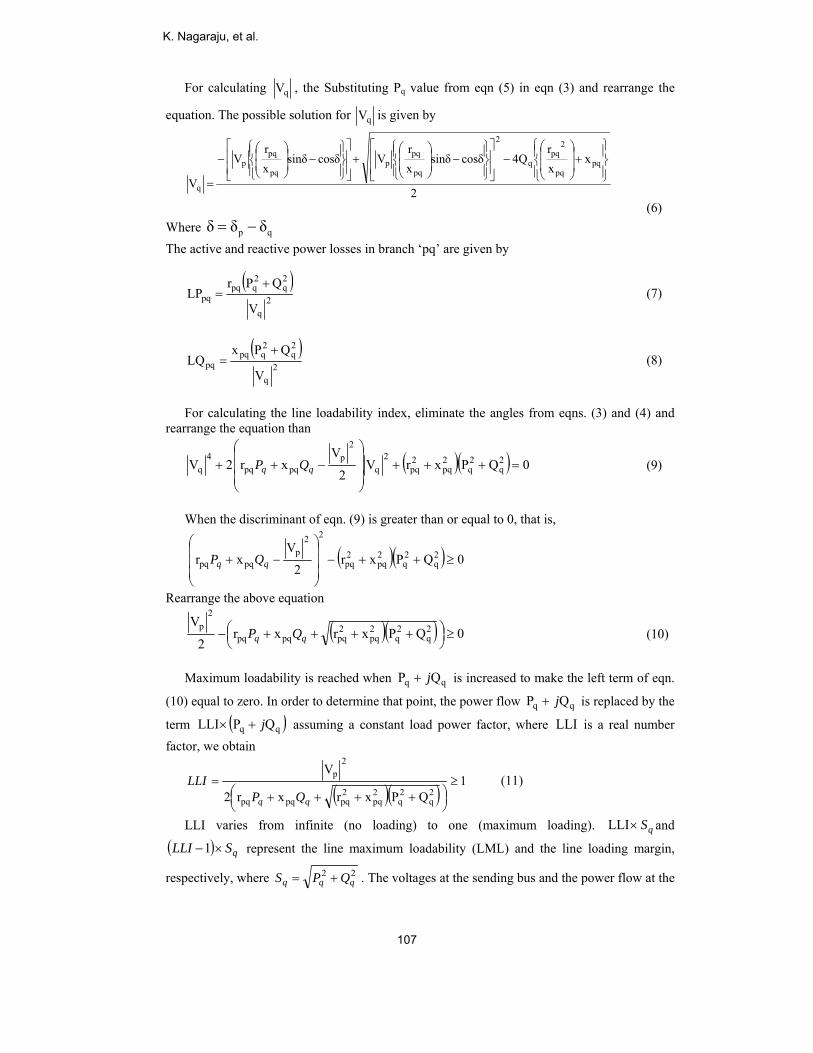
receiving bus for all lines in a distribution system can be obtained by load flow calculations [45]. Then the LLI of each line can be calculated easily and quickly. The line with the minimal LLI is the weakest line, and its receiving bus is the weakest bus. The line will reach the critical loading condition when line LLI is approaches 1.0, thus the system will become critical to lose voltage stability. The preceding analysis is for a line in a RDS that may have any number of nodes and depicts only the megavolt ampere (MVA) capacity of a line to carry load. As an example, consider a distribution line as shown in Figure 2.
Figure 2. A simple model of RDS branch for LLIi calculation
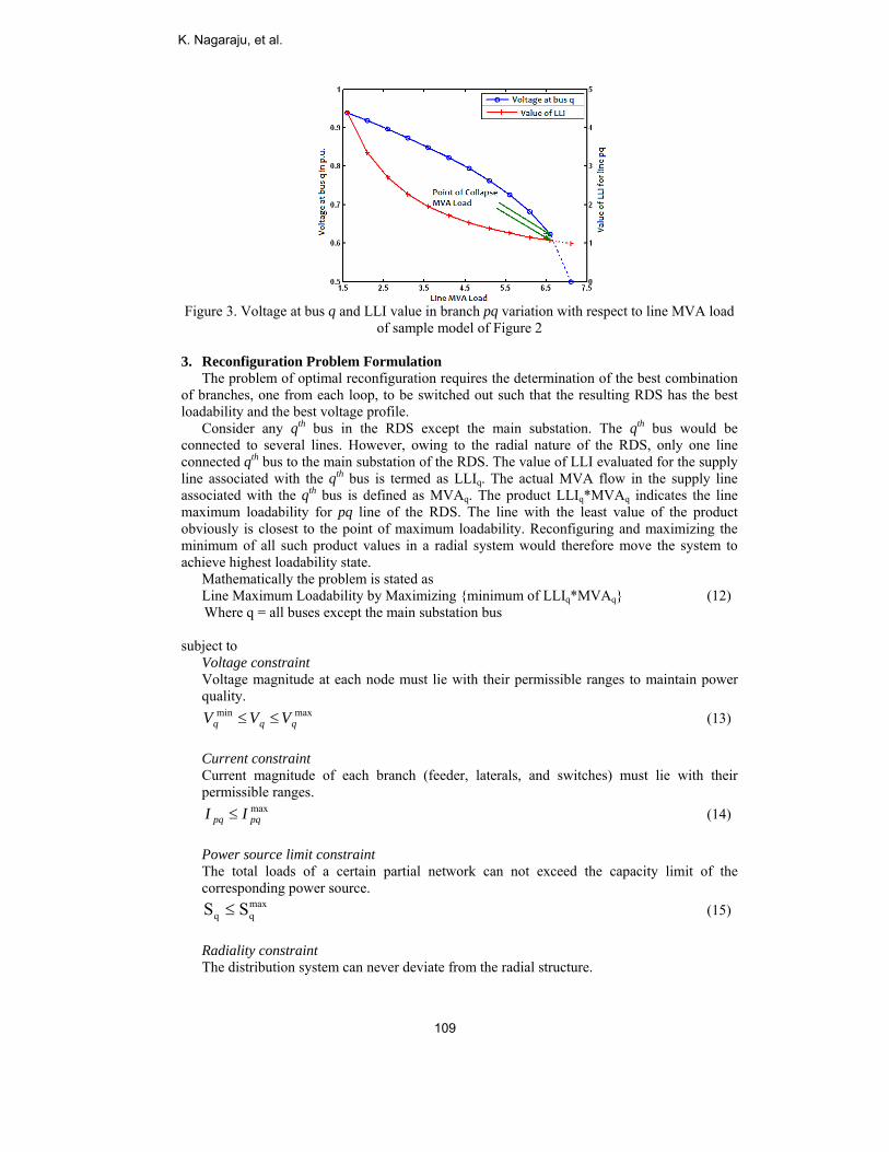
The sending end voltage is assumed to be Vp∠δp = 1.0∠0.0. The value of LLI is evaluated for various values of power flow through the line and the results are tabulated in Table 1. For each step of loading, the fourth column of Table.1 reports the value of line loadability MVA margin. It is equal to the maximum possible additional power flow in the line when the value of LLI is greater than 1.0 or the minimum power flow decrement to establish solvability of the power flow equation when the value of LLI is less than 1.0. At an Sq of 7.10 MVA, the value of LLI is equal to 0.99. This indicates that a reduction of load to the extent of 0.066 MVA to reach 7.034 MVA restores solvability of the power flow equation for the line and increases LLI to 1.0. In a similar view, at a MVA load of 1.60, the value of LLI is equal to 4.40. This indicates that an increase of power flow by 5.434 MVA to reach 7.034 MVA reduces LLI to 1.0 and moves the line to the point of maximum loadability. Figure 3 depicts graphically the change in line load and its effect on the value of LLI and voltage magnitude at bus q. Table 1 Relationship between MVA load, LLI, and line loading MVA margin in line pq for sample model
Heuristic Approach for Distribution Systems Feeder Reconfiguration to Line Maximum Loadability
108
Figure 3. Voltage at bus q and LLI value in branch pq variation with respect to line MVA load
of sample model of Figure 2 3. Reconfiguration Problem Formulation The problem of optimal reconfiguration requires the determination of the best combination of branches, one from each loop, to be switched out such that the resulting RDS has the best loadability and the best voltage profile. Consider any qth bus in the RDS except the main substation. The qth bus would be connected to several lines. However, owing to the radial nature of the RDS, only one line connected qth bus to the main substation of the RDS. The value of LLI evaluated for the supply line associated with the qth bus is termed as LLIq. The actual MVA flow in the supply line associated with the qth bus is defined as MVAq. The product LLIq*MVAq indicates the line maximum loadability for pq line of the RDS. The line with the least value of the product obviously is closest to the point of maximum loadability. Reconfiguring and maximizing the minimum of all such product values in a radial system would therefore move the system to achieve highest loadability state. Mathematically the problem is stated as Line Maximum Loadability by Maximizing {minimum of LLIq*MVAq} (12) Where q = all buses except the main substation bus subject to Voltage constraint Voltage magnitude at each node must lie with their permissible ranges to maintain power quality. maxmin
qqq VVV ≤≤ (13) Current constraint Current magnitude of each branch (feeder, laterals, and switches) must lie with their permissible ranges. max
pqpq II ≤ (14) Power source limit constraint The total loads of a certain partial network can not exceed the capacity limit of the corresponding power source. max
qq SS ≤ (15) Radiality constraint The distribution system can never deviate from the radial structure.
K. Nagaraju, et al.
109
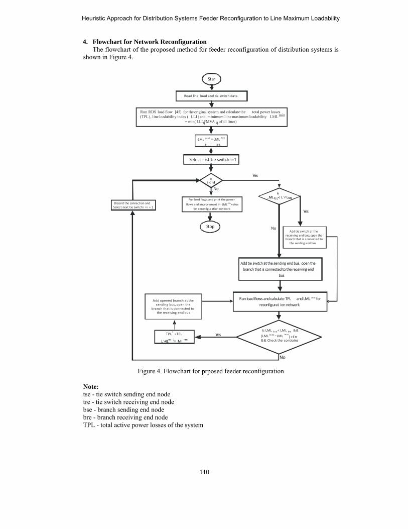
4. Flowchart for Network Reconfiguration The flowchart of the proposed method for feeder reconfiguration of distribution systems is shown in Figure 4.
Yes
No
No
Yes
Yes
Star
Run RDS load flow [45] for the original system and calculate the total power losses (TPL), line loadability index ( LLI ) and minimum l ine maximum loadability LMLmin
= min( LLIq*MVA q of all lines)
Select first tie switch i=1
Is
Is
flow and improvement in LMLmin value
Run load flows and print the power
s for reconfiguration network
Add tie switch at the receiving end bus; open the branch that is connected to
the sending end bus
Add tie switch at the sending end bus, open the branch that is connected to the receiving end
bus
Run load flows and calculate TPL and LML min for reconfigurat ion network
Is LML bse< LML bre && min1 ‐(LML LML min
) >Err&& Check the contrains
TPL1=TPL
Add opened branch at the sending bus, open the
branch that is connected to the receiving end bus
Discard the connection and Select next tie switch i = i + 1
Read line, load and tie switch data
LMLmin1 = LML min
1
Stop
No
Figure 4. Flowchart for prposed feeder reconfiguration
Note: tse - tie switch sending end node tre - tie switch receiving end node bse - branch sending end node bre - branch receiving end node TPL - total active power losses of the system
Heuristic Approach for Distribution Systems Feeder Reconfiguration to Line Maximum Loadability
110
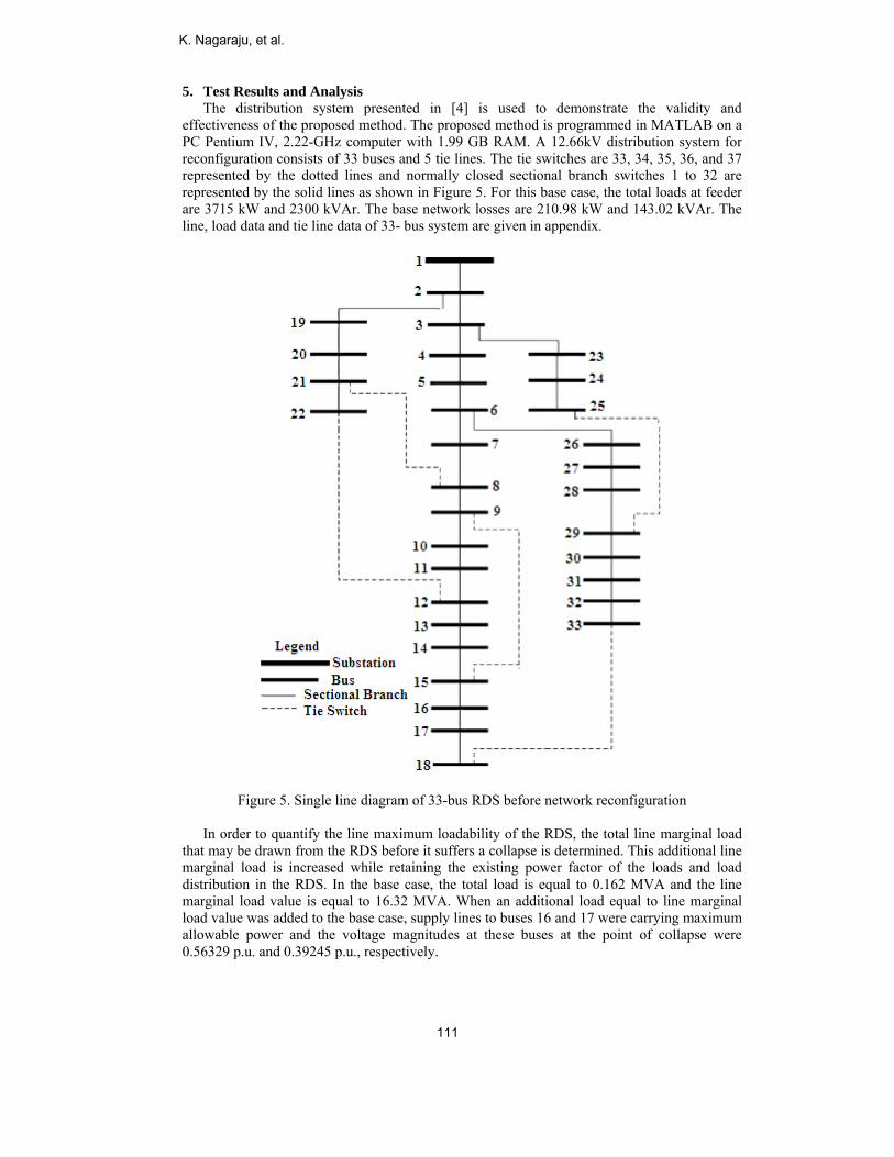
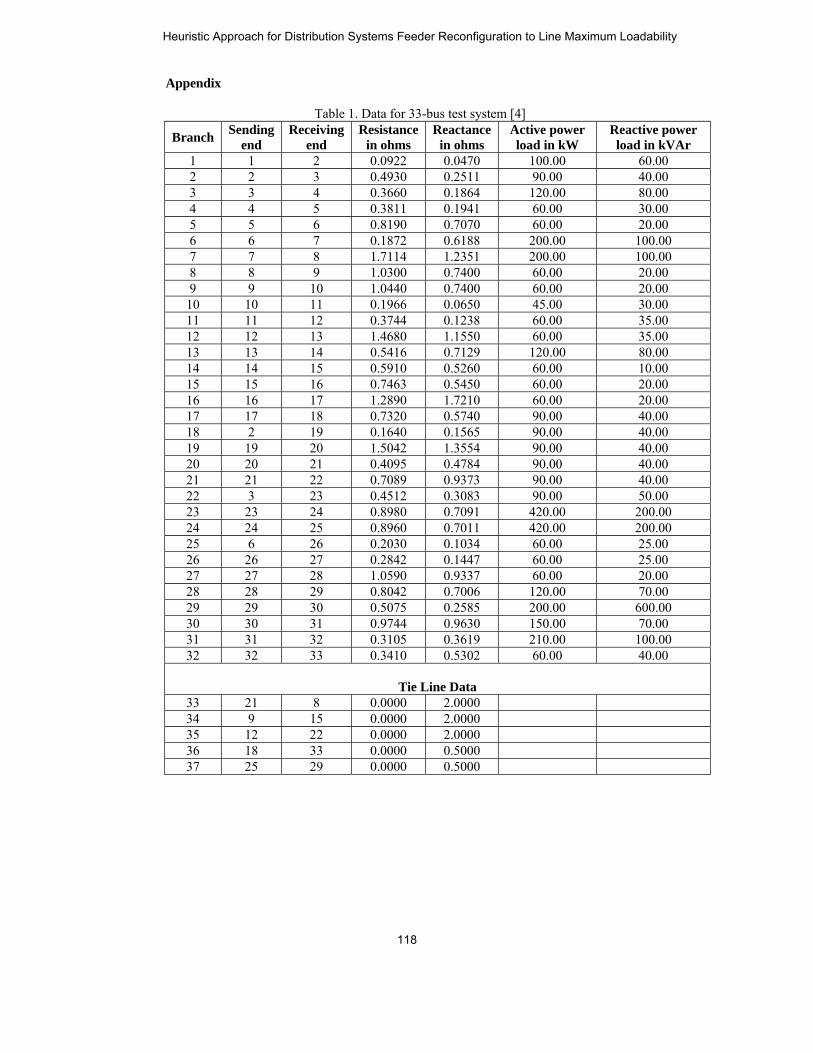
5. Test Results and Analysis The distribution system presented in [4] is used to demonstrate the validity and effectiveness of the proposed method. The proposed method is programmed in MATLAB on a PC Pentium IV, 2.22-GHz computer with 1.99 GB RAM. A 12.66kV distribution system for reconfiguration consists of 33 buses and 5 tie lines. The tie switches are 33, 34, 35, 36, and 37 represented by the dotted lines and normally closed sectional branch switches 1 to 32 are represented by the solid lines as shown in Figure 5. For this base case, the total loads at feeder are 3715 kW and 2300 kVAr. The base network losses are 210.98 kW and 143.02 kVAr. The line, load data and tie line data of 33- bus system are given in appendix.
Figure 5. Single line diagram of 33-bus RDS before network reconfiguration In order to quantify the line maximum loadability of the RDS, the total line marginal load that may be drawn from the RDS before it suffers a collapse is determined. This additional line marginal load is increased while retaining the existing power factor of the loads and load distribution in the RDS. In the base case, the total load is equal to 0.162 MVA and the line marginal load value is equal to 16.32 MVA. When an additional load equal to line marginal load value was added to the base case, supply lines to buses 16 and 17 were carrying maximum allowable power and the voltage magnitudes at these buses at the point of collapse were 0.56329 p.u. and 0.39245 p.u., respectively.
K. Nagaraju, et al.
111
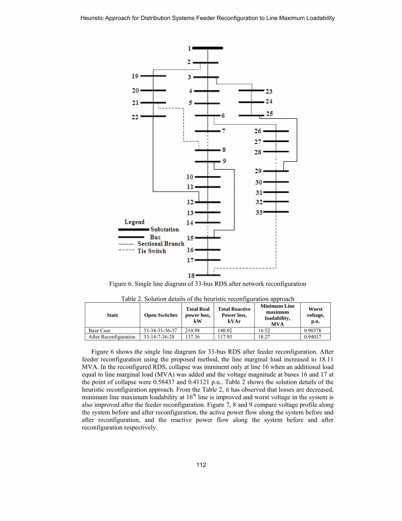
Figure 6. Single line diagram of 33-bus RDS after network reconfiguration
Table 2. Solution details of the heuristic reconfiguration approach
State Open Switches Total Real power loss,
kW
Total Reactive Power loss,
kVAr
Minimum Line maximum loadability,
MVA
Worst voltage,
p.u.
Base Case 33-34-35-36-37 210.98 140.02 16.52 0.90378 After Reconfiguration 33-14-7-36-28 137.36 117.93 18.27 0.94037
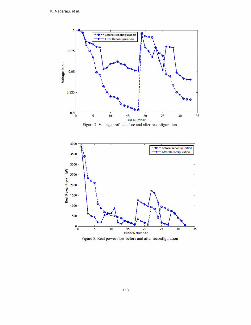
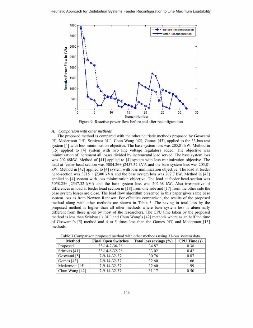
Figure 6 shows the single line diagram for 33-bus RDS after feeder reconfiguration. After feeder reconfiguration using the proposed method, the line marginal load increased to 18.11 MVA. In the reconfigured RDS, collapse was imminent only at line 16 when an additional load equal to line marginal load (MVA) was added and the voltage magnitude at buses 16 and 17 at the point of collapse were 0.58437 and 0.41121 p.u.. Table 2 shows the solution details of the heuristic reconfiguration approach. From the Table 2, it has observed that losses are decreased, minimum line maximum loadability at 16th line is improved and worst voltage in the system is also improved after the feeder reconfiguration. Figure 7, 8 and 9 compare voltage profile along the system before and after reconfiguration, the active power flow along the system before and after reconfiguration, and the reactive power flow along the system before and after reconfiguration respectively.
Heuristic Approach for Distribution Systems Feeder Reconfiguration to Line Maximum Loadability
112
Figure 7. Voltage profile before and after reconfiguration
Figure 8. Real power flow before and after reconfiguration
K. Nagaraju, et al.
113
Figure 9. Reactive power flow before and after reconfiguration
A. Comparison with other methods The proposed method is compared with the other heuristic methods proposed by Goswami [5], Mcdermott [15], Srinivasa [41], Chun Wang [42], Gomes [43], applied to the 33-bus test system [4] with loss minimization objective. The base system loss was 205.81 kW. Method in [15] applied to [4] system with two line voltage regulators added. The objective was minimization of increment all losses divided by incremental load served. The base system loss was 202.68kW. Method of [41] applied to [4] system with loss minimization objective. The load at feeder head-section was 5084.26+ j2457.32 kVA and the base system loss was 205.81 kW. Method in [42] applied to [4] system with loss minimization objective. The load at feeder head-section was 3715 + j2300 kVA and the base system loss was 202.7 kW. Method in [43] applied to [4] system with loss minimization objective. The load at feeder head-section was 5058.25+ j2547.32 kVA and the base system loss was 202.68 kW. Also irrespective of differences in load at feeder head section in [18] from one side and [17] from the other side the base system losses are close. The load flow algorithm presented in this paper gives same base system loss as from Newton Raphson. For effective comparison, the results of the proposed method along with other methods are shown in Table 3. The saving in total loss by the proposed method is higher than all other methods where base system loss is abnormally different from those given by most of the researchers. The CPU time taken by the proposed method is less than Srinivasa’s [41] and Chun Wang’s [42] methods where as an half the time of Goswami’s [5] method and 4 to 5 times less than the Gomes [43] and Mcdermott [15] methods.
Table 3 Comparison proposed method with other methods using 33-bus system data.
Method Final Open Switches Total loss savings (%) CPU Time (s) Proposed 33-14-7-36-28 34.87 0.38 Srinivas [41] 33-14-8-32-28 33.02 0.42 Goswami [5] 7-9-14-32-37 30.76 0.87 Gomes [43] 7-9-14-32-37 32.60 1.66 Mcdermott [15] 7-9-14-32-37 32.60 1.99 Chun Wang [42] 7-9-14-32-37 31.17 0.50
Heuristic Approach for Distribution Systems Feeder Reconfiguration to Line Maximum Loadability
114
The number of load flows required to get the optimum solution by the proposed algorithm is only 8, whereas it is 26 in case of Srinivasa [41] and 29 for the case of Baran and Wu [4]. Since the test case system is small (33 buses) and above results are obtained on 12 years time span the CPU time differences may be understood to be due to development in computers. However, some percent of CPU time difference is only due to this reason, recalling that the proposed algorithm gives the optimum solution with a few numbers of load flow runs (8 compared to 26 runs in Ref. [41]). Therefore, this method can be effectively used in real time application of the large distribution system under widely varying load conditions, where the CPU time will be a major point of comparison. 6. Conclusions This paper presents a line loadability index that quantifies the margin to maximum loadability for any distribution line when the sending end voltage is kept constant. This index is simple to use and also guides to compute the extent of load reduction to restore solvability of power flow equations. This paper further develops a heuristic approach reconfiguration method for radial distribution systems. The proposed scheme is based upon maximizing the line maximum loadability. The algorithm gives the solution with a few numbers of switching operations, load flow runs and the CPU time needed is small compared to that in all publications. Comparison of different methods for distribution network reconfiguration suggested that heuristic approaches may not determine global optimum but they are suitable for real time distribution system reconfiguration for loss minimization. Thus, the proposed technique represents an improved, more efficient method which can easily solve the distribution network reconfiguration problem including maximization of line loadability compared with other methods. References [1] Merlin, A., and Back, H., “Search for a minimal loss operating spanning tree
configuration in an urban power distribution system”, Proc. 5th Power System Computation Conf., Cambridge, UK, 1975, pp. 1–18.
[2] Shirmohammadi, D., and Hong, H.W., “Reconfiguration of electric distribution networks for resistive line loss reduction”, IEEE Trans. Power Deliv., 1989, vol. 4, no. 2, pp. 1492–1498.
[3] Civanlar, S., Grainger, J.J., Yin, H., and Lee, S.H., “Distribution feeder reconfiguration for loss reduction”, IEEE Trans. Power Deliv., 1988, vol. 3, no. 3, pp. 1217–1223.
[4] Baran, M.E., and Wu, F.F., “Network reconfiguration in distribution for loss reduction and load balancing”, IEEE Trans. Power Syst., 1989, vol. 4, no. 3, pp. 1401–1407.
[5] Goswami, S.K., and Basu, S.K., “A new algorithm for the reconfiguration of distribution feeders for loss minimization”, IEEE Trans. Power Deliv., 1992, vol. 7, no. 3, pp. 1484–1491.
[6] Taylor, T., and Lubkeman, D., “Implementation of heuristic strategies for distribution feeder reconfiguration”, IEEE Trans. Power Deliv., 1990, vol. 5, no. 1, pp. 239–246.
[7] Wagner, T.P., Chikhani, A.Y., and Hackam, R., “Feeder reconfiguration for loss reduction”, IEEE Trans. Power Deliv., 1991, vol. 6, no. 4, pp. 1922–1933.
[8] Glaomocanin, V., “Optimal loss reduction of distribution networks”, IEEE Trans. Power Syst., 1990, vol. 5, no. 3, pp. 774–781.
[9] Borozan, V., Rajicic, D., and Ackovski, R., “Improved method for loss minimization in distribution networks”, IEEE Trans. Power Syst., 1995, vol. 10, no. 3, pp. 1420–1425.
[10] Sarfi, R.J., Salama, M.M.A., and Chikhani, A.Y., “A survey of the state of the art in distribution system reconfiguration for system loss reduction”, Electr. Power Syst. Res., 1994, vol. 31, pp. 61–70.
[11] Sarfi, R.J., Salama, M.M.A., and Chikhani, A.Y., “Distribution system reconfiguration for loss reduction: an algorithm based on network partitioning theory”, IEEE Trans. Power Syst., 1996, vol. 11, no. 1, pp. 504–510.
K. Nagaraju, et al.
115
[12] Roytelman, I.,Melnik, V., Lee, S.S.H., and Lugtu,R.L., “Multi-objective feeder reconfiguration by distribution system management system”, IEEE Trans. Power Syst., 1996, vol. 11, no. 2, pp. 661–667.
[13] Jiang, D., and Baldick, R., “Optimal electric distribution system reconfiguration and capacitor control”, IEEE Trans. Power Syst., 1996, vol. 11, no. 2, pp. 890–897.
[14] Peponis, G.J., Papadopoulos, M.P., and Hatziargyriou, N.D., “Optimal operation of distribution networks”, IEEE Trans. Power Syst., 1996, vol. 11, no. 1, pp. 59–67.
[15] McDermott, T.E., Drezga, I., and Broad Water, R.P., “A heuristic non-linear constructive method for distribution system reconfiguration”, IEEE Trans. Power Syst., 1998, vol. 14, no. 2, pp. 478–483.
[16] Lin W.M., Chin H.C., “A new approach for distribution feeder reconfiguration for loss reduction and service restoration”, IEEE Trans. Power Del. 1998, vol. 13, no. 3, pp. 870–875.
[17] R.P. Broadwater, A.H. Khan, H.E. Shalan, R.E. Lee, “Time varying load analysis to reduce distribution losses through reconfiguration”, IEEE Trans. Power Del., 1993, vol. 8, no. 1, pp. 294–300.
[18] Gomes, F.V., Carneiro, S., Pereira, J.L.R., Vinagre, M.P., and Garcia, P.A.N., “A new heuristic reconfiguration algorithm for large distribution systems”, IEEE Trans. Power Syst., 2005, vol. 20, no. 3, pp. 1373–1378.
[19] Gomes, F.V., Carneiro, S., Pereira, J.L.R., Vinagre, M.P., and Garcia, P.A.N., “A new distribution system reconfiguration approach using optimum power flow and sensitivity analysis for loss reduction”, IEEE Trans. Power Syst., 2006, vol. 21, no. 4, pp. 1616–1623.
[20] Schmidt, H.P., Ida, N., Kagan, N., and Guaraldo, J.C., “Fast reconfiguration of distribution systems considering loss minimization”, IEEE Trans. Power Syst., 2005, vol. 20, no. 3, pp. 1311–1319.
[21] Chen, C.S., and Cho, M.Y., “Energy loss reduction by critical switches”, IEEE Trans. Power Deliv., 1993, vol. 8, no. 3, pp. 1246–1253.
[22] Zhou, Q., Shirmohammadi, D., and Liu, W.H.E., “Distribution feeder reconfiguration for operation cost reduction”, IEEE Trans. Power Syst., 1997, vol. 12, no. 2, pp. 724–729.
[23] Taleski, R., and Rajicic, D., “Distribution network reconfiguration for energy loss reduction”, IEEE Trans. Power Syst., 1997, vol. 12, no.1, pp. 293–406.
[24] Chiang, H.D., and Jean-Jameau, R.M., “Optimal network reconfiguration in distribution systems, Part 1: a new formulation and a solution methodology”, IEEE Trans. Power Deliv., 1990, vol. 5, no. 4, pp. 1902–1909.
[25] Chiang, H.D., and Jean-Jameau, R.M., “Optimal network reconfiguration in distribution systems, Part 2: solution algorithms and numerical results”, IEEE Trans. Power Deliv., 1990, vol. 5, no. 3, pp. 1568–1574.
[26] Cheng, H.C., and Kuo, C.C., “Network reconfiguration in distribution systems using simulated annealing”, Electr. Power Syst. Res., 1994, vol. 29, pp. 227–238.
[27] Jeaon, Y.J., Kim, J.C., Kim, J.O., Shin, J.R., and Lee, K.Y., “An efficient simulated annealing algorithm for network reconfiguration in large-scale distribution systems”, IEEE Trans. Power Deliv., 2002, vol. 17, no. 4, pp. 1070–1078.
[28] Morton, A.B., and Mareels, I.M., “An efficient brute-force solution to the network reconfiguration problem”, IEEE Trans. Power Syst., 2000, vol. 15, no. 3, pp. 996–1000.
[29] Das, D., “A fuzzy multi-objective approach for network reconfiguration of distribution systems”, IEEE Trans. Power Deliv., 2006, vol. 21, no. 1, pp. 202–209.
[30] Nara, K., Shiose, A., Kitagawa, M., and Ishihara, T., “Implementation of genetic algorithm for distribution system loss minimum reconfiguration”, IEEE Trans. Power Syst., 1992, vol. 7, no. 3, pp. 1044–1051.
[31] Zhu, J.Z., “Optimal reconfiguration of electrical distribution network using the refined genetic algorithm”, Electr. Power Syst. Res., 2002, vol. 62, pp. 37–42.
Heuristic Approach for Distribution Systems Feeder Reconfiguration to Line Maximum Loadability
116
[32] Lopez, E., Opazo, H., Garcia, L., and Bastard, P., “Online reconfiguration considering variability demand: applications to real networks”, IEEE Trans. Power Syst., 2004, vol. 19, no. 1, pp. 549–553.
[33] Hong, Y.Y., and Ho, S.Y., “Determination of network configuration considering multi-objective in distribution systems using genetic algorithms”, IEEE Trans. Power Syst., 2005, vol. 20, no. 2, pp. 1062–1069.
[34] Chiou, J.P., Chung, C.F., and Su, C.T., “Variable scaling hybrid differential evolution for solving network reconfiguration of distribution systems”, IEEE Trans. Power Syst., 2005, vol. 20, no. 2, pp. 668–674.
[35] Mendoza, J., Lopez, R., Morales, D., Lopes, E., Dessante, P., and Moraga, R., “Minimal loss reconfiguration using genetic algorithms with restricted population and addressed operators: real application”, IEEE Trans. Power Syst., 2006, vol. 21, no. 2, pp. 948–954.
[36] Hsiao, Y.T., “Multi-objective evolution programming method for feeder reconfiguration”, IEEE Trans. Power Syst., 2004, vol. 19, no. 1, pp. 594–599.
[37] Ramos, E.R., Exposito, A.G., Santos, J.R., and Iborra, F.L., “Path-based distribution network modeling: application to reconfiguration for loss reduction”, IEEE Trans. Power Syst., 2005, vol. 20, no. 2, pp. 556–564.
[38] D. Mary and M. Ravichandra Babu, “Network reconfiguration for loss minimization by optimal operations in distribution systems”, Int. J. Recent Trends Eng., 2009, vol. 2, no. 3, 129–131.
[39] E. Dolatdar, S. Soleymani and B. Mozafari, “A New Distribution Network Reconfiguration Approach using a Tree Model”, World Academy of Science, Engineering and Technology, 2009, vol. 5, pp. 1186–1193.
[40] J-.H. Teng, “A direct approach for distribution system load flow solutions”, IEEE Trans. Power Del., 2000, vol. 18, no. 3, pp. 1085–1091.
[41] R. Srinivasa Rao and S.V.L. Narasimham, “A new heuristic approach for optimal network reconfiguration in distribution systems”, Int. J. Appl. Sci. Eng. Technol., 2009, vol. 5, no. 1, pp. 15–21.
[42] C. Wang and H.Z. Cheng, “Optimization of network configuration in large distribution systems using plant growth simulation algorithm”, IEEE Trans. Power Syst., 2008, vol. 23, no.1, pp. 119–126.
[43] F. V. Gomes, S. Carneiro, J. L. R. Pereira and M. P. Vinagre, “A new heuristic reconfiguration algorithm for large distribution systems”, IEEE Trans. Power Syst., 2005, vol. 20, no. 3, pp. 1373–1378.
[44] C. W. Taylor, Power System Voltage Stability, ser. EPRI Power System Engineering Series. New York: McGraw-Hill, 1994, pp. 10–16.
[45] K. Nagaraju, S. Sivanagaraju, T. Ramana, and P. V. Prasad, “A novel load flow method for radial distribution systems including realistic loads”, Electric Power Components and Systems International Journal. 2011, vol. 39, pp. 128-141.
Heuristic Approach for Distribution Systems Feeder Reconfiguration to Line Maximum Loadability
118
transmissjournals a
distributethan 100 national a
research generationresearch pInstitute o
engineerinwith the distributiotransmissin refereesociety of
K. NB.TecS.V.USystempursuIndia.Ongoplann
ion systems (Fand conference
S. SivreceivAndhrsystempowerAssocAssocIndia.
d generation aresearch pape
awards (Pandit
T. RareceivJNT UindustpursuiPradeLimiteVigna
interests are n and flexiblepapers in referof Engineers (I
V. G1974engindegreand AnanUniveProfe
ng, JNTUCE, JNTUCE, Pul
on system plaion systems (F
ed journals andf India, Life me
Nagaraju wasch. degree inUniversity, Tirum from the J
uing the Ph.D. d. Currently, hele. Andhra Pra
ning, power quFACTS). He h
es proceedings.
vanagaraju wved the B.Techra University, ms from IIT, Kr system from ciate Professor ciate Professor His research
and flexible acers in refereed
Madan Mohan
amana was boved the B.TechUniversity, Hytrial drives froing the Ph.Dsh, India. Cued, Bangalorean's Engineeridistribution s
e ac transmissireed journals anIndia), Life me
Ganesh was bo. He receive
neering from thee in power sy
the Ph.D. dentapur in 2010ersity, Anantap
essor and heaPulivendula, K
livendula, Kadanning, powerFACTS) and smd conferences embership of t
s born in Tadn electrical upathi in 1999JNT Universidegree at the JNe is Associateadesh, India. Huality, reliabilihas published
was born in Kadh. degree in elec
VisakhapatnaKharagpur in JNT Universiin JNT Unive
r with the JNTinterests are di transmission journals and c
n Malaviya me
orn in Proddatuh. degree in elecyderabad in 20om JNT Unive. degree at trrently, he is
e, Karnataka. ing College, Vystem planninion systems (Fnd conferencesmber of Indian
orn in Jammad the B.Techhe JNT Univestem operationegree in elec. He is currenpur, Andhra Pad of the deKadapa, Andhdapa, Andhra r quality, reliamart grid. He hproceedings. Mechnical educa
dipatri, Andhraand electron
9 and M.Techity, AnantapurNT University professor in
His research inteity, distributedmore than 15
dapa, Andhra Pctrical and elec
am in 1998, th2010 and theity, Hyderabadrsity, Kakinad
T University, Aistribution systsystems (FACconferences pr
emorial prize an
ur, Andhra Practrical and elec000 and the Mersity, Kakinathe JNT Univ
a Business AHe was a AVadlamudi, Ang, power quFACTS). He hs proceedings.n Society for T
alamadugu, Anh. degree in
ersity, Hyderabn and control fctrical engineently pursuing tradesh, India.epartment in
hra pradesh. Hpradesh, India
ability, distribuhas published mMr. Ganesh is ation.
a Pradesh. Heics engineerin
h degree in Elr in 2005. H
y, Kakinada, AnS.S.N Engineerests are distr
d generation a research pape
Pradesh on Julyctronics enginehe M.Tech dee Ph.D. degreed in 2004. Cura, Andhra PradAnantapur, Antem planning,
CTS). He has proceedings. Hend Best paper p
adesh on Julyctronics engine
M.Tech degree ada in 2010. Hversity, AnantAnalyst in HP
Assistant ProfeAndhra Pradesality, reliabilihas published Mr. Ramana i
Technical Educa
ndhra Pradesh electrical an
bad in 1998 anfrom SV Univeering from JNthe Ph.D. degrCurrently, he Electrical an
He was a Assisa. His researchuted generatiomore than 15 r
Life members
e received theng from theectrical Powere is currentlyndhra Pradesh,
eering College,ribution systemand flexible acers in refereed
y 01, 1970. Heeering from thegree in powere in electricalrrently, he is adesh. He was andhra Pradesh,power quality,
published moree received twoprize award).
y 04, 1978. Heeering from the
in power andHe is currentlytapur, AndhraP Global Softessor with thesh, India. Histy, distributedmore than 30
is Associate ofation.
on June 15,nd electronicsnd the M.Techersity, Tirupati


![Informed [Heuristic] Search - University of Delawaredecker/courses/681s07/pdfs/04-Heuristic...Informed [Heuristic] Search Heuristic: “A rule of thumb, simplification, or educated](https://static.documents.pub/doc/80x56/5aa1e13c7f8b9a84398c48b6/informed-heuristic-search-university-of-delaware-deckercourses681s07pdfs04-heuristicinformed.jpg)