42
Stratus Stratus Customer Service Documentation Hexadecimal Display Bulk Power Supply Subsystem HB–052060 Service Bulletin
Stratus
������
�� ���� �������
����������
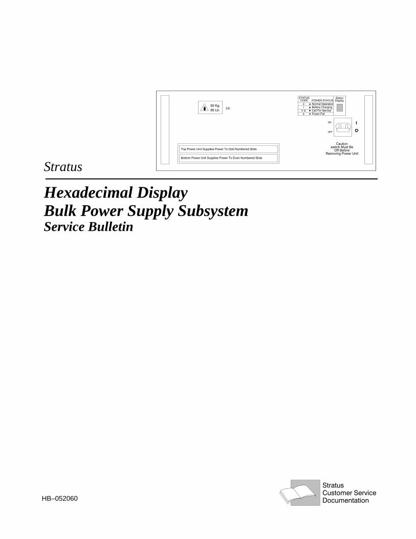
Hexadecimal DisplayBulk Power Supply Subsystem
HB–052060
Service Bulletin


StratusCustomer Service Documentation
Hexadecimal DisplayBulk Power Supply Subsystem Service Bulletin

NoticeThe information contained in this document is subject to change without notice.
STRATUS COMPUTER INC. MAKES NO WARRANTY OF ANY KIND WITH REGARD TO THIS MATERIAL,INCLUDING, BUT NOT LIMITED TO, THE IMPLIED WARRANTIES OF MERCHANTABILITY AND FITNESSFOR A PARTICULAR PURPOSE. Stratus Computer, Inc., shall not be liable for errors contained herein or incidental orconsequential damages in connection with the furnishing, performance, or use of this material.
Continuous Processing, FTX, SQL/2000, SQL/2000 logo, StrataLINK, StrataNET, Stratus, the Stratus logo, VOS, and XAare registered trademarks of Stratus Computer, Incorporated
Manual Name: Hexadecimal Display Bulk Power Supply Subsystem Service BulletinPart Number: HB–052060Revision Number: 0First Printing: January, 1994
Stratus Computer, IncorporatedCustomer Service Documentation Department55 Fairbanks BoulevardMarlboro, MA 01752–1298
WarningThe equipment documented in this manual generates and uses radio frequency energy, which if not installed and used instrict accordance with the instructions in this manual, may cause harmful interference to radio communications. Theequipment has been tested and found to comply with the limits for a Class A computing device pursuant to Subpart J of Part15 of FCC rules, which are designed to provide reasonable protection against such interference when operated in acommercial environment.
Operation of this equipment in a residential area is likely to cause interference, in which case the user at his own expensewill be required to take whatever measures may be required to correct the interference.
Copyright� 1994 by Stratus Computer, Inc. All rights reserved.

iiiHexadecimal Display Bulk Power Supply Subsystem Service Bulletin (HB–052060)
Preface
The Hexadecimal Display Bulk Power Supply Subsystem Service Bulletin (HB–052060) describes the new Stra-tus power subsystem which is compatible with nearly all Stratus modules.
This Bulletin is organized as follows.
Section 1 Product Overview
Section 2 Product Specifications
Section 3 Hardware and Software Requirements
Section 4 Parts Lists
Section 5 Theory of Operation
Section 6 Interface Signals and Functions
Section 7 Troubleshooting
Section 8 Removal and Replacement Procedures
Appendix Interconnection Diagrams
AudienceThis guide is intended for authorized service personnel who install and maintain Stratus systems, and whohave completed Stratus field–service training courses.
Related DocumentationThe following is a list of related Customer Service documentation.
� Hexadecimal Display Bulk Power Supply Subsystem Service Announcement (HA052)
� Module Control Panel Service Announcement (HA043)
� 2500–Watt Power System Service Announcement (HA048)
� 2500–Watt Power System Service Bulletin (HB048)
� 40–Slot Systems Maintenance Guide (HM001)
� XA/R 10–Slot Maintenance Guide (HM020)
� XA/R 28–Slot Maintenance Guide (HM021)
� Stratus XA/R Model 5 and 25 Maintenance Guide (HM025)

iv Hexadecimal Display Bulk Power Supply Subsystem Service Bulletin (HB–052060)
Document ConventionsThis manual uses different fonts to indicate filenames, computer input, computer output, as well as variables.The following is an example:
remove_disk_pack slot_number drive_number
Literal Values
Bold words or characters in formats and command descriptions represent commands or keywords that youmust use literally. Filenames and user input is also in bold. (See example above.)
User–Supplied Values
Italic words or characters in computer input or output represent variables. An example of a variable is thedrive_number shown above.
Computer Output
The information that the system display on the system console appears in courier font.
Problems, Questions, and SuggestionsYou can comment on this manual by using the comment_on_manual command described in the VOSSystem Administration Guide (R012) or by sending email to CSM_Comments. Comments received areevaluated and added to the CSM bug list.
To use comment_on_manual, type comment_on_manual <RETURN> and then complete the form thatappears on your screen. You must fill in the manual’s part number (HB–052060). When you have completedthe form, press <ENTER>. Your comments are sent to Stratus over the Remote Service Network. Note thatVOS includes your name with your comments.
You may also comment on this manual by filling out the user comment form at the back of this book andmailing it in.
Stratus welcomes any corrections and suggestions for improving this manual.
Safety
WARNING: To prevent personal injury, the entire orderly power–down proceduremust be performed as described.
CAUTION: One open fuse will not cause a module crash but two open fuses will.

vHexadecimal Display Bulk Power Supply Subsystem Service Bulletin (HB–052060)
Table of Contents
1. Product Overview 1. . . . . . . . . . . . . . . . . . . . . . . . . . . . . . . . . . . . . . . . . . . . . . . . . . . . . . . . . . . . . . . . . . . .
2. Product Specifications 2. . . . . . . . . . . . . . . . . . . . . . . . . . . . . . . . . . . . . . . . . . . . . . . . . . . . . . . . . . . . . . . . .
3. Hardware and Software Requirements 3. . . . . . . . . . . . . . . . . . . . . . . . . . . . . . . . . . . . . . . . . . . . . . . . . . .
4. Parts Lists 4. . . . . . . . . . . . . . . . . . . . . . . . . . . . . . . . . . . . . . . . . . . . . . . . . . . . . . . . . . . . . . . . . . . . . . . . . . .
5. Theory of Operation 4. . . . . . . . . . . . . . . . . . . . . . . . . . . . . . . . . . . . . . . . . . . . . . . . . . . . . . . . . . . . . . . . . .
5.1 Power Supply 5. . . . . . . . . . . . . . . . . . . . . . . . . . . . . . . . . . . . . . . . . . . . . . . . . . . . . . . . . . . . . . . . . . . 5.2 Power Controller 5. . . . . . . . . . . . . . . . . . . . . . . . . . . . . . . . . . . . . . . . . . . . . . . . . . . . . . . . . . . . . . . . . 5.3 Upper Power Backplane Card 5. . . . . . . . . . . . . . . . . . . . . . . . . . . . . . . . . . . . . . . . . . . . . . . . . . . . . . . 5.4 Lower Power Backplane Card 5. . . . . . . . . . . . . . . . . . . . . . . . . . . . . . . . . . . . . . . . . . . . . . . . . . . . . . . 5.5 Block Diagram 5. . . . . . . . . . . . . . . . . . . . . . . . . . . . . . . . . . . . . . . . . . . . . . . . . . . . . . . . . . . . . . . . . . 5.6 Machine States 7. . . . . . . . . . . . . . . . . . . . . . . . . . . . . . . . . . . . . . . . . . . . . . . . . . . . . . . . . . . . . . . . . .
5.6.1 Battery Backup 8. . . . . . . . . . . . . . . . . . . . . . . . . . . . . . . . . . . . . . . . . . . . . . . . . . . . . . . . . . . . .
6. Interface Signals and Functions 9. . . . . . . . . . . . . . . . . . . . . . . . . . . . . . . . . . . . . . . . . . . . . . . . . . . . . . . . .
7. Troubleshooting 10. . . . . . . . . . . . . . . . . . . . . . . . . . . . . . . . . . . . . . . . . . . . . . . . . . . . . . . . . . . . . . . . . . . . . .
7.1 Status Codes – Faults and Fixes 11. . . . . . . . . . . . . . . . . . . . . . . . . . . . . . . . . . . . . . . . . . . . . . . . . . . . . 7.2 Fuse Fault Troubleshooting 11. . . . . . . . . . . . . . . . . . . . . . . . . . . . . . . . . . . . . . . . . . . . . . . . . . . . . . . . . 7.3 Troubleshooting Modules with Assorted Power Subsystem Assemblies 13. . . . . . . . . . . . . . . . . . . . . .
7.3.1 Upper (Odd) Power Backplane Card 13. . . . . . . . . . . . . . . . . . . . . . . . . . . . . . . . . . . . . . . . . . . . 7.3.2 Lower (Even) Power Backplane Card 14. . . . . . . . . . . . . . . . . . . . . . . . . . . . . . . . . . . . . . . . . . . . 7.3.3 Upper (Odd) Bulk Power Supply Drawer Status 14. . . . . . . . . . . . . . . . . . . . . . . . . . . . . . . . . . . 7.3.4 Lower (Even) Bulk Power Supply Drawer 15. . . . . . . . . . . . . . . . . . . . . . . . . . . . . . . . . . . . . . . .
8. Orderly Power–down and Restart 15. . . . . . . . . . . . . . . . . . . . . . . . . . . . . . . . . . . . . . . . . . . . . . . . . . . . . . .
8.1 Orderly Power–down 16. . . . . . . . . . . . . . . . . . . . . . . . . . . . . . . . . . . . . . . . . . . . . . . . . . . . . . . . . . . . . 8.2 Restart 18. . . . . . . . . . . . . . . . . . . . . . . . . . . . . . . . . . . . . . . . . . . . . . . . . . . . . . . . . . . . . . . . . . . . . . . . .
9. Removal and Replacement Procedures 19. . . . . . . . . . . . . . . . . . . . . . . . . . . . . . . . . . . . . . . . . . . . . . . . . . .
9.1 Bulk Power Supply Drawers 19. . . . . . . . . . . . . . . . . . . . . . . . . . . . . . . . . . . . . . . . . . . . . . . . . . . . . . . . 9.1.1 Removal 19. . . . . . . . . . . . . . . . . . . . . . . . . . . . . . . . . . . . . . . . . . . . . . . . . . . . . . . . . . . . . . . . . . 9.1.2 Replacement 21. . . . . . . . . . . . . . . . . . . . . . . . . . . . . . . . . . . . . . . . . . . . . . . . . . . . . . . . . . . . . . .
9.2 Upper Power Backplane and Upper Power Backplane Fuses 22. . . . . . . . . . . . . . . . . . . . . . . . . . . . . . . 9.2.1 Upper Power Backplane Removal and Replacement 22. . . . . . . . . . . . . . . . . . . . . . . . . . . . . . . . 9.2.2 Fuse Removal and Replacement on Upper Power Backplane Card 23. . . . . . . . . . . . . . . . . . . . .
9.3 Lower Power Backplane Card and Fuses 24. . . . . . . . . . . . . . . . . . . . . . . . . . . . . . . . . . . . . . . . . . . . . . 9.3.1 Lower Power Backplane Card 24. . . . . . . . . . . . . . . . . . . . . . . . . . . . . . . . . . . . . . . . . . . . . . . . . . 9.3.2 Lower Power Backplane Card Fuse Removal and Replacement 26. . . . . . . . . . . . . . . . . . . . . . .
Appendix A–1. . . . . . . . . . . . . . . . . . . . . . . . . . . . . . . . . . . . . . . . . . . . . . . . . . . . . . . . . . . . . . . . . . . . . . . . . . . . . . . . .

vi Hexadecimal Display Bulk Power Supply Subsystem Service Bulletin (HB–052060)
List of Figures
Figure 1. Status Display on Bulk Power Supply Drawer 1. . . . . . . . . . . . . . . . . . . . . . . . . . . . . . . . . . . . . . . . . . . . Figure 2. Battery Sensing Thresholds 3. . . . . . . . . . . . . . . . . . . . . . . . . . . . . . . . . . . . . . . . . . . . . . . . . . . . . . . . . . Figure 3. Hex Display Bulk Controller Fault Reporting and Display Block Diagram 6. . . . . . . . . . . . . . . . . . . . . Figure 4. Status Display 11. . . . . . . . . . . . . . . . . . . . . . . . . . . . . . . . . . . . . . . . . . . . . . . . . . . . . . . . . . . . . . . . . . . . Figure 5. New Module Control Unit Control Panel 16. . . . . . . . . . . . . . . . . . . . . . . . . . . . . . . . . . . . . . . . . . . . . . . Figure 6. Old Control Panel 16. . . . . . . . . . . . . . . . . . . . . . . . . . . . . . . . . . . . . . . . . . . . . . . . . . . . . . . . . . . . . . . . . Figure 7. Circuit Breakers on Bulk Power Supply Drawers 17. . . . . . . . . . . . . . . . . . . . . . . . . . . . . . . . . . . . . . . . Figure 8. Contactor Housing Assembly Circuit Breakers in OFF position. 17. . . . . . . . . . . . . . . . . . . . . . . . . . . . . Figure 9. Contactor Housing Assembly Circuit Breakers 18. . . . . . . . . . . . . . . . . . . . . . . . . . . . . . . . . . . . . . . . . . Figure 10. Circuit Breakers on Bulk Power Supply Drawer 19. . . . . . . . . . . . . . . . . . . . . . . . . . . . . . . . . . . . . . . . . Figure 11. Triggers and Locking Levers on Bulk Power Supply Drawer 20. . . . . . . . . . . . . . . . . . . . . . . . . . . . . . . Figure 12. Bulk Power Supply Drawer Safety Latches 21. . . . . . . . . . . . . . . . . . . . . . . . . . . . . . . . . . . . . . . . . . . . . Figure 13. Upper Power Backplane Card 22. . . . . . . . . . . . . . . . . . . . . . . . . . . . . . . . . . . . . . . . . . . . . . . . . . . . . . . . Figure 14. Fuses and LEDs on Upper Power Backplane Card 23. . . . . . . . . . . . . . . . . . . . . . . . . . . . . . . . . . . . . . . . Figure 15. Locations of Screws on Lower Power Backplane Card 24. . . . . . . . . . . . . . . . . . . . . . . . . . . . . . . . . . . . Figure 16. Fuses and LEDs on Lower Power Backplane Card 25. . . . . . . . . . . . . . . . . . . . . . . . . . . . . . . . . . . . . . . Figure A–1. Hexadecimal Display Bulk Power Supply Drawer Block Diagram A–2. . . . . . . . . . . . . . . . . . . . . . . . . Figure A–2. Hexadecimal Display Bulk Power Supply Controller Block Diagram A–3. . . . . . . . . . . . . . . . . . . . . . .
List of Tables
Table 1. AC Input Specifications 2. . . . . . . . . . . . . . . . . . . . . . . . . . . . . . . . . . . . . . . . . . . . . . . . . . . . . . . . . . . . .
Table 2. Bulk Power Specifications 2. . . . . . . . . . . . . . . . . . . . . . . . . . . . . . . . . . . . . . . . . . . . . . . . . . . . . . . . . . .
Table 3. Battery Sensing 2. . . . . . . . . . . . . . . . . . . . . . . . . . . . . . . . . . . . . . . . . . . . . . . . . . . . . . . . . . . . . . . . . . . .
Table 4. Bulk Power Sensing 3. . . . . . . . . . . . . . . . . . . . . . . . . . . . . . . . . . . . . . . . . . . . . . . . . . . . . . . . . . . . . . . .
Table 5. Hex Display Bulk Power Subsystem Field Replaceable Units 4. . . . . . . . . . . . . . . . . . . . . . . . . . . . . . . .
Table 6. Other Bulk Power Supply Drawers (FRUs) 4. . . . . . . . . . . . . . . . . . . . . . . . . . . . . . . . . . . . . . . . . . . . . .
Table 7. Power Subsystem Machine States 7. . . . . . . . . . . . . . . . . . . . . . . . . . . . . . . . . . . . . . . . . . . . . . . . . . . . . .
Table 8. Input Signals 9. . . . . . . . . . . . . . . . . . . . . . . . . . . . . . . . . . . . . . . . . . . . . . . . . . . . . . . . . . . . . . . . . . . . . .
Table 9. Output Signals 9. . . . . . . . . . . . . . . . . . . . . . . . . . . . . . . . . . . . . . . . . . . . . . . . . . . . . . . . . . . . . . . . . . . . .
Table 10. System Interface Signals 10. . . . . . . . . . . . . . . . . . . . . . . . . . . . . . . . . . . . . . . . . . . . . . . . . . . . . . . . . . . .
Table 11. Status Codes – Faults and Fixes 11. . . . . . . . . . . . . . . . . . . . . . . . . . . . . . . . . . . . . . . . . . . . . . . . . . . . . .
Table 12. Lower Power Backplane Card Fuse Faults 12. . . . . . . . . . . . . . . . . . . . . . . . . . . . . . . . . . . . . . . . . . . . . .
Table 13. Upper Power Backplane Card Fuse Faults 13. . . . . . . . . . . . . . . . . . . . . . . . . . . . . . . . . . . . . . . . . . . . . .
Table 14. Upper Power Backplane Card Cable Connections 22. . . . . . . . . . . . . . . . . . . . . . . . . . . . . . . . . . . . . . . .
Table 15. Lower Power Backplane Card Cable Connections 25. . . . . . . . . . . . . . . . . . . . . . . . . . . . . . . . . . . . . . . .

1Hexadecimal Display Bulk Power Subsystem Service Bulletin (HB-052060)
1. Product OverviewThe hexadecimal display bulk power subsystem consists of the 2500–watt bulk power supply draw-ers with a new status display and new upper and lower power backplane cards. The new power back-plane cards have status LEDs and field–replaceable fuses. Other enhancements of this subsysteminclude extended battery life and greater mean time between failures (MTBF). The design goal of thenew power subsystem is to reduce the number of power subsystem assembly replacements by in-creasing MTBF and improving diagnostic capability.
The status display on the bulk power supply drawers replaces the less informative set of POWER ON(Green), BATTERY OK, and BATTERY CHARGING LED indicators previously used. (SeeFigure 1.)
���
Figure 1. Status Display on Bulk Power Supply Drawer
The new upper and lower power backplane cards report error information to the status display. Inaddition, there is an LED on each power backplane card that monitors the status of its associatedfuse. An LED remains lighted as long as there is incoming voltage and its associated fuse is notopen.
For the 28–slot G862–based modules, a new transformer tub/fan tray assembly and cable are plannedfor future release. The new tub/fan tray assembly will enable single and multiple fan fault sensing. Asingle amber LED on the new fan pack will indicate failure, and the new cable will relay fan faults tothe upper power backplane card. The upper power backplane card reports to the hex display.

2 Hexadecimal Display Bulk Power Supply Subsystem Service Bulletin (HB-052060)
2. Product SpecificationsTable 1 and Table 2 list the electrical specifications for the hex display bulk power supply subsystem.
Table 1. AC Input Power Specifications
Input Voltage 170VAC – 264VAC 50/60 Hz
Input Current 16 amps maximum
Table 2. Bulk Power Drawer Specifications
AC Input Voltage 19 – 29Vac
Input Current 122 amps RMS maximum
DC Output Voltage 18 – 28Vdc
DC Output Current 120 amps maximum
Holdup (without batteries) 16msec minimum
Maximum Battery Current 150 amps, fuse protected
The following table lists the battery sensing specifications for the bulk power supply drawer.
Table 3. Battery Sensing
Low Battery Threshold –––> Nominal value (voltage rising): 23.7 +/–5%
Bat Good Threshold –––> Nominal value (voltage decreasing): 23.7 +/–5%
Bat Good Threshold –––> Nominal value (voltage rising): 25.5 +/–5%
Hi Bat –––> ~12 Volts – Prevents drawer from starting with ashort across the battery. (UL test)
Bat Sense –––> Charger voltage should not exceed 34 Volts
Battery Float Voltage –––> Nominal value: 27.4 Volts +/–4%
Figure 2 illustrates the information displayed in Table 3.

3Hexadecimal Display Bulk Power Subsystem Service Bulletin (HB-052060)
CHARGE LIMIT CHARGE LIMIT
0
12V
23.7
27
34 34
27
25.5
12V
INVALIDWILL NOT POWER ON
FLOAT
BAT GOOD
LOW BAT
FLOAT
BAT GOOD
BAT LOW
HI BAT
Figure 2. Battery Sensing Thresholds
The following table lists the bulk power sensing specifications for the bulk power supply drawers.
Table 4. Bulk Power Sensing
Bulk A Threshold –––> Nominal value (voltage decreasing): 18.3 +/–5%
Bulk A Threshold –––> Nominal value (voltage rising: 21.1 +/–5%
3. Hardware and Software RequirementsThe subsystem is configurable with the 10–slot, 12–slot, 28–slot, and XA/2000 40–slot Stratus mod-ules.
NOTE: The new upper power backplane card (AA–E21133) is not compatible withnon–TUV 40–slot modules. This is due to the fact that the ac fan connectors have beeneliminated from the new card. The new lower power backplane card (AA–E21113) isnot compatible with non–XA/2000 40–slot modules.
NOTE: The tone circuit used on StrataLINK systems has been eliminated from the hexdisplay bulk power supply drawers. A module which uses this feature (auto start–up formodules on the StrataLINK system) must contain AA–E22500 bulk power supply draw-ers.
The subsystem has no minimum operating system requirements.

4 Hexadecimal Display Bulk Power Supply Subsystem Service Bulletin (HB-052060)
4. Parts ListsThis section contains a list of the field replaceable units that comprise the hex display bulk powersupply subsystem plus lists of other pertinent boards and assemblies.
The following table lists the hex display bulk power subsystem FRUs.
Table 5. Hex Display Bulk Power Subsystem Field Replaceable Units
Part Number Description
AA–E22230 hex display bulk power supply drawer
AA–E21133 upper power backplane card
AA–E21113 lower power backplane card
FF–000032 10–amp 32v fuse, F002 and F003 on upper power backplane card
FF–000033 4–amp fuse, F001, F004, F005 on upper power backplane card
FF–000035 30–amp 32v fuse, F001–F004 on lower power backplane card
Table 6. Other Bulk Power Supply Drawers (FRUs)
Part Number Description Where Used
AA–E21200 1800 watt bulk power FRU 40–slot CPU, St. Charles
AA–E22200 2500 watt bulk drawer FRU 40–slot, 28–slot Atlantic, St Charles
AA–E22230 2500 watt bulk drawer FRUwith hex display
40–slot, 28–Slot Atlantic, St. Charles
AA–E22500 1800 watt bulk drawer FRUwith tone
40–slot systems that use tone
5. Theory of OperationThis section describes the theory of operation for the hex display bulk power supply subsystem and adefinition of the machine states of the power subsystem. It also contains a Fault Reporting and Dis-play block diagram of the hex display bulk controller board.
The bulk power supply drawers each work in conjunction with a bulk power transformer and a reso-nating capacitor. Each drawer contains rectifiers, filter capacitors, batteries, a shunt resistor and acontrol board. The upper bulk power supply drawer supplies power to the upper power backplanecard and to the boards in the odd–numbered logic chassis slots. The lower bulk power supply drawersupplies power to the lower power backplane card and to the boards in the even–numbered logicchassis slots.
Each bulk power supply drawer receives 24Vac directly from the CVT transformer and full wave rec-tifies this voltage into a semi–regulated +24Vdc output. The filter capacitors are located after the fullwave rectifiers. They filter the rectified dc voltage and provide the energy storage that allows thebatteries enough time to turn on during a powerfail. The shunt resistor prevents excessive outputvoltage by turning on when (primarily during lightly loaded conditions) the bulk voltage rises abovethe specified threshold.

5Hexadecimal Display Bulk Power Subsystem Service Bulletin (HB-052060)
5.1 Power Supply
The +5V (Vcc) power source supplies power to the power controller board logic (AP–E22230) and tothe hex display board (AP–E21202), both of which are located in the bulk power supply drawer.This voltage receives ORed power from three sources and is active during the entire power fail pro-cess.
5.2 Power Controller
The power controller board contains a state machine, the battery charger, output control dictated bythe state machine and voltage sensing. Circuitry on the power controller board contains up to fourvoltages for threshold sensing, bulk drawer fan sensing, power problem LED display drivers, andbulk power supply drawer fault sensing.
5.3 Upper Power Backplane Card
The upper power backplane card transmits the FAN_FAULT (SFF/single fan fault) and Multiple FanFailure (MFF) signals from the power tub fans to the upper (odd) bulk power supply drawer and tothe lower (even) power backplane card. It also relays unsensed, fused voltage sources to the odd bulkpower supply drawer for fuse/voltage source sensing. These voltages form FUSE_FAIL2 within thebulk power supply drawer. Green LEDs and pullups have been added for voltage source identifica-tion. A J004 connector has been added to accept the tub fan tray connector (28–slot G862 modulesonly) that is in design now and will be released later.
5.4 Lower Power Backplane Card
The lower power backplane card accepts FAN_FAULT (SFF) and Multiple Fan Failure (MFF) sig-nals and relays them to the controller board on the lower (even) bulk power supply drawer. It alsorelays sense voltages from 30 amp fused outputs to the lower bulk power supply drawer controllerboard. Green LEDs and pullups have been added for voltage source identification.
5.5 Block Diagram
The following block diagram of the hex display bulk controller illustrates Fault Reporting and Dis-play on the Hex Display Bulk Power Subsystem.

6H
exa
de
cima
l Disp
lay B
ulk P
ow
er S
up
ply S
ub
system
Se
rvice B
ulle
tin (H
B-0
52
06
0)
Figure 3. Hex Display Bulk Controller Fault Reporting and Display Bolck Diagram
Tub Fan Tray
Fan Fault Lines(2)
2
Upper Power BackplaneAP–E21133–00
FusesFuse Sense
Odd/EvenBulk SenseLines (2)
Lower Power BackplaneAP–E21113–00
Fuses
Odd/Even Bulk SenseLines (2)
Existing Interface Lines
Tub Fan Sense
Bulk Power
Fuse Sense
Fuse SenseComparators
Bulk Power Sense
Tub Fan Sense
False Error Correction
10:4 Encoder
HexDisplay Driver
Display Blanking
Hex Display
EVEN BULK DRAWER E22230
10:4 Encoder
Sense
False Error Correction
Existing Interface Lines
Hex Display
E22230Fan Sense
E22230Fan Sense
E22230 E22230
E22230 E22230
Faults
Faults
Battery Sense
Battery Sense
HexDisplay Driver
Display Blanking
ODD BULK DRAWER E22230
0 Normal1 Battery Charging2 Bulk Fan Fail3 BP Fuse Fail4 Bulk Drawer Fault5 Single Tub Fan Fail6 Mult Tub Fan Fail7 Odd Bulk Fail8 Even Bulk Fail9 AC PowerFail
0 Normal1 Battery Charging2 Bulk Fan Fail3 BP Fuse Fail4 Bulk Drawer Fault5 Single Tub Fan Fail6 Mult Tub Fan Fail7 Odd Bulk Fail8 Even Bulk Fail9 AC PowerFail
60
HEX DISPLAY BULK POWER SUBSYSTEMFAULT REPORTING AND DISPLAY BLOCK DIAGRAM
E22230 Fans
E22230 Fans
Lines (4)
Fuse Sense Lines (4)

7Hexadecimal Display Bulk Power Subsystem Service Bulletin (HB-052060)
5.6 Machine States
This section defines the seven possible machine states of the power subsystem from the time that acis initially applied to the cabinet through full power fail. These states are based on inter–operation ofthe CPU with the power subsystem.
Table 7. Power Subsystem Machine States
MachineState
Definition
OFF OFF is the power subsystem state when there is no ac Power is applied to the cabinet orwhen the main circuit breaker(s) is/are in the OFF position. This state should not be con-fused with powerfail.
IDLE IDLE is the power subsystem state when AC power is applied to the cabinet, but thefront panel START switch has not been activated. In this state, power is active within thebulk power supply subsystem awaiting issue of the START command. When the SHUT-DOWN command is issued or the STOP switch on the front panel is activated after themodule has been operating, the module returns to the IDLE state.
NO–STATE At initial boot but prior to relay of the SYSTEM GREEN LIGHT signal from the CPU, themodule is in NO–STATE. NO–STATE is also the state of the power subsystem when themodule is suspended. The NO–STATE condition is contingent upon the following threeconditions:
1/ AC power within regulation2/ front panel START switch actuated3/ bulk power within regulation.
RUN The power subsystem is in the RUN state after the NO–STATE requirements have beenmet and when the CPU has sent the SYSTEM GREEN LIGHT signal and the module isoperating normally.
STORE(RIDE–THROUGH)
When in the RUN state but AC power is outside acceptable range (typically less than170 VAC), loss of AC power is sensed and the AC FAIL signal is sent to the CPU. WhenAC FAIL is sent to the CPU, the batteries automatically go online to back up +24 VDCbulk power. At this time the CPU begins the power fail process by storing memory.Approximately six seconds later the CPU activates CPU KILL BAT, which in turn acti-vates the MEM HOLD state.
NOTE: To initiate the power fail process, the AC FAIL signal is required from both bulkpower drawers. NOTE: If the CPU does not activate CPU KILL BAT , the batteries remain on until a 40second internal timer de–activates them or until they reach the Battery Low threshold.The Battery Low threshold resets the state machine into the IDLE state.

8 Hexadecimal Display Bulk Power Supply Subsystem Service Bulletin (HB-052060)
Table 7. Power Subsystem Machine States (cont.)
MachineState
Definition
MEM HOLD MEM HOLD is the state of the power subsystem after the CPU activates the CPU KILLBAT signal and follows the STORE state. When in the MEM HOLD state, main batterypower is turned off, and a separate BAT OUT output power source connected to the bulkpower supply drawer batteries turns on. BAT OUT powers the memory boards, half ofthe CPU logic chassis fans, and the module clock card(s).
The MEM HOLD state is maintained until AC Power is within regulation range or untilbattery voltage has reached the Battery Low threshold. Although the official specificationcalls for MEM HOLD to last 20 minutes, this state is maintained as long as the batteryhas energy, and depends upon:� the battery charge state prior to the powerfail occurrence,� the system configuration/load.
BATTERYLASTED
BATTERY LASTED is the power subsystem state immediately after ac power has beenrestored while the power subsystem is still in the MEM HOLD state. When ac power andbulk power is restored, the bulk power supply drawer relays the BATTERY LASTEDsignal to the CPU, indicating to the CPU that battery power to the memory boards wasmaintained and that the information held in memory was not lost. The CPU then per-forms a recovery. After the CPU is operational, the SYSTEM GREEN LIGHT signal issent to the bulk power supply drawer, at which time the power subsystem state changesfrom BATTERY LASTED to RUN.
NOTE: The state machine on the power controller board has been modified such that whenthe system is in STORE or MEM, the control panel IMMEDIATE POWER OFF will shut downthe power subsystem.
5.6.1 Battery Backup
Once the power subsystem detects AC FAIL, the batteries maintain the module for approximately sixseconds. After this point the module changes to the MEM HOLD state. Once the module entersMEM HOLD, the batteries maintain the memory boards, module clock card(s), and some coolingfans in service. The duration of the MEM HOLD time depends on the type of memory boards used.(See below.)
30 Minute MEM HOLD:
All configurations that precede the introduction of the M61X series memory boards are guaranteed30 minutes of memory backup time for the expected life of the battery. The expected life of the bat-tery is four years,
20 Minute MEM HOLD:
All 40–slot and 28–slot configurations support a 20 minute memory backup period for the expectedlife of the battery. The expected life of the battery is four years.
NOTE: A module may exceed the guaranteed MEM HOLD period depending upon thestrength of the batteries and the configuration.

9Hexadecimal Display Bulk Power Subsystem Service Bulletin (HB-052060)
6. Interface Signals and FunctionsThe tables in this section list the interface signals and functions used on the hex display bulk powersubsystem.
Table 8 and Table 9 describe the CPU Interface Signals for the hex display bulk power subsystem.
Table 8. Input Signals
Signal Name Active State Description
SYS_GREEN_LT LOW Indicates that the CPU is active. The power subsystem staysin an idle state until the CPU indicates that it is ready.
SHUTDOWN A/SHUTDOWN B
LOW CPU shutdown commands, both of which are required to turnoff the power subsystem. SHUTDOWN A is derived by theCPU(s) in the ODD slots. SHUTDOWN B is derived by theCPU(s) in the EVEN slots.
TEST FROM CPU HIGH Signal used by diagnostics to test the powerfail process. Whenthe power subsystem is in the RUN state, TEST causes thestate to change to STORE and the initiation of battery backup.
START LOW Control panel start command that turns on the power subsys-tem.
STOP LOW Control panel stop command that turns off the power subsys-tem. STOP has been modified on the new drawer design sothat the power subsystem can be shut OFF in the STORE andMEM states, as well as in the RUN state. E21200 and E22200bulk power subsystems can only be stopped in the RUN state.
CPU KILL BAT LOW Input signal from the CPU that changes the power subsystemstate from STORE to MEM.
CPU 5V VOLTAGE SOURCE
VOLTAGESOURCE
+5 volt DC voltage source generated on CPU board(s) Vccplane and distributed to the bulk power supply drawer. A pullupsource for all isolated CPU interface signals.
The following table describes the output signals for the hex display bulk power subsystem.
Table 9. Output Signals
Signal Name Active State Description
AC FAIL LOW Initiates powerfail sequence. In a system operating normally,AC FAIL is required from both bulk power supply drawers toinitiate the powerfail process.
BATTERY LASTED LOW Initiates a quick boot process and indicates: � that the battery survived the ac powerfail,� to the CPU that the data saved in memory is valid.
BATTERY OK LOW Indicates that the battery is charged and ready for a full power-fail. This status signal does not cause the system to abort thepowerfail process.
FAN OK HIGH Active low indicates a fan failure in one or more of the CPUlogic chassis fan modules or a fan failure within the bulk powersupply subsystem.

10 Hexadecimal Display Bulk Power Supply Subsystem Service Bulletin (HB-052060)
The following table describes the system interface signals for the power subsystem.
Table 10. System Interface Signals
Signal Name Active State Description
NEXT_CABINET_ON LOW Turns on sequential PK 54 peripheral cabinets associatedwith the main CPU cabinet. This signal is controlled by theSTART/STOP circuitry in the bulk power supply drawer.
NEXT_CABINET_START LOW Generated directly from the bulk drawer start relay. Primaryuse is for turning on ac peripheral cabinets.
NEXT_CABINET_+12 VOLTAGESOURCE
+12 volt DC power source. Used as a pullup on the isolatedCPU ground referenced side of the peripheral ac controlleropto–isolators.
FAN +12 VOLTAGESOURCE
+12 volt, bulk power ground reference. Voltage source forexclusive use by the control panel.
SYS_RED_LIGHT LOW Inhibits activity to the control panel red light if the powersubsystem is not in the ON state. Contains a +12 volt pul-lup source and an inhibit.
BATTERY LIGHT VOLTAGESOURCE
+12 volt source generated directly from the battery. Indi-cates that the module is operating on battery power.
PANEL GREEN LIGHT HIGH Bulk power supply drawer signal derived from the systemgreen light received from the CPU. The bulk drawer isolatesthe signal and provides a +12 volt pullup source.
FAN GND LOW SIGNAL FAN GND is a return signal (not a ground) derived from thedaisy–chained module fan sensing. A 4.7 ohm resistor thatforms a voltage divider when the FAN MOD OK signal isopened ties this signal to bulk return in the bulk power sup-ply drawer.
FAN MOD OK ACTIVE HIGH FAN MOD OK is located at the opposite end of the CPUlogic chassis fan sensing network from FAN GND. An openin the fan sense string causes a 1k pullup in the bulk powersupply drawer to pull FAN MOD OK high.
7. TroubleshootingThis section describes the troubleshooting features of the hex display power subsystem, the defini-tions of the status codes that appear on the hex display, and the effects of mixing and matching hexdisplay power subsystem assemblies with old power subsystem assemblies. It also describes in detailthe circuits that the fuses on the upper and lower power backplane cards protect, and the failures thatoccur when the fuses are open.
Status code 0 on the hex display power supply drawer indicates normal operation. Status code 1 onthe hex display power supply drawer indicates that the battery is charging. Status codes 2–8 indicatea failure of some kind. These failures are described in detail in the following subsection. Status code9 indicates a power failure. Figure 4 is an illustration of the hex status display on the bulk powersupply drawer.

11Hexadecimal Display Bulk Power Subsystem Service Bulletin (HB-052060)
Figure 4. Status Display
7.1 Status Codes – Faults and Fixes
The following is a facsimile of the status codes label that is attached to the main cabinet. It includesa list likely fixes for the fault conditions.
Table 11. Status Codes – Faults and Fixes
Code Power Status Description Power System Service Action
0 Normal Operation None.
1 Battery Charging No problem if charging light is on less than 24 hours.
2 Bulk Fan Failure Replace bulk power supply.
3 Power Supply Failure Replace bulk power supply.
4 Backplane Power Card Fuse Failure 1. Check green LEDs on lower power backplane card if evensupply reports failure.2. Check green LEDs on upper power backplane card if oddsupply reports failure.
5* Transformer Tub Single Fan Failure Replace transformer tub fan pack at next scheduled preven-tive maintenance.
6* Transformer Tub Multi–Fan Failure Replace transformer tub fan pack immediately.
7 Odd Bulk Loss of Power Check incoming power on odd bulk power supply. If incom-ing power is okay, replace odd bulk power supply.
8 Even Bulk Failure Check incoming power on even bulk power supply. If incom-ing power is okay, replace even bulk power supply.
9 Power Fail Possible tripped circuit breaker, disconnected power cord, orutility outage.
*Not applicable on 40–slot modules and not yet implemented on 28–slot G862 modules.
12 Hexadecimal Display Bulk Power Supply Subsystem Service Bulletin (HB-052060)
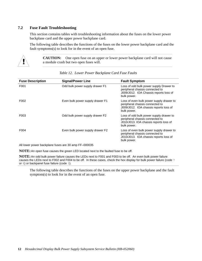
7.2 Fuse Fault Troubleshooting
This section contains tables with troubleshooting information about the fuses on the lower powerbackplane card and the upper power backplane card.
The following table describes the functions of the fuses on the lower power backplane card and thefault symptoms(s) to look for in the event of an open fuse.
CAUTION: One open fuse on an upper or lower power backplane card will not causea module crash but two open fuses will.
Table 12. Lower Power Backplane Card Fuse Faults
Fuse Description Signal/Power Line Fault Symptom
F001 Odd bulk power supply drawer F1 Loss of odd bulk power supply Drawer toperipheral chassis connected toJ009/J012. IOA Chassis reports loss ofbulk power.
F002 Even bulk power supply drawer F1 Loss of even bulk power supply drawer toperipheral chassis connected toJ009/J012. IOA chassis reports loss ofbulk power.
F003 Odd bulk power supply drawer F2 Loss of odd bulk power supply drawer toperipheral chassis connected toJ010/J013. IOA chassis reports loss ofbulk power.
F004 Even bulk power supply drawer F2 Loss of even bulk power supply drawer toperipheral chassis connected toJ010/J013. IOA chassis reports loss ofbulk power.
All lower power backplane fuses are 30 amp FF–000035
NOTE: An open fuse causes the green LED located next to the faulted fuse to be off.
NOTE: An odd bulk power failure causes the LEDs next to F001 and F003 to be off. An even bulk power failurecauses the LEDs next to F002 and F004 to be off. In these cases, check the hex display for bulk power failure (code 7or 8) or backpanel fuse failure (code 3).
The following table describes the functions of the fuses on the upper power backplane and the faultsymptom(s) to look for in the event of an open fuse.

13Hexadecimal Display Bulk Power Subsystem Service Bulletin (HB-052060)
Table 13. Upper Power Backplane Card Fuse Faults
Fuse Description Signal/Power Line Fault Symptom
F001 (4 amp, FF–000033) Mem Fan 24 V Loss of 24Vdc to the logic chassis fansthat remain on during power fail. Maybe accompanied by system error logentry for fan fault.
F002 (10 amp, FF–000032) This fan – ORed with That fan signal toprevent fan failure as long as the partnersignal is good.
Loss of 24Vdc to the logic chassis fans.Unless both F2 and F3 are both blown,will not result in loss of any fans.
F003 (10 amp, FF–000032) That fan – ORed with This fan signal toprevent fan failure as long as the partnersignal is good.
Loss of 24Vdc to the CPU logic chassifans. Unless both F2 and F3 are bothblown, will not result in loss of any fans.
F004 (4 amp, FF–000033) Even fused battery for HOLD state. Loss of one ORed 24Vdc power sourcethat creates BAT COM. BAT COM pow-ers the module clock card during powerfail. This fuse does not have an LED.Fault can be determined only duringMEM HOLD.
F005 (4 amp, FF–000033) Odd fused battery for HOLD state. Loss of one ORed 24Vdc power sourcethat creates BAT COM. BAT COM pow-ers the module clock card during powerfail. This fuse does not have an LED.Fault can be determined only duringMEM HOLD.
NOTE: Loss of bulk power does not affect any of these LEDs.
NOTE: An open fuse causes the green LED located next to the fuse to be off.
7.3 Troubleshooting Modules with Assorted Power Subsystem Assemblies
This subsection describes troubleshooting considerations that pertain to mixing and matching hexdisplay power subsystem assemblies with old power subsystem assemblies.
7.3.1 Upper (Odd) Power Backplane Card
Installation of a new upper power backplane card alone without any of the other new subsystem as-semblies provides visual display of the presence or absence of fused voltages by way of the greenLEDs on the card. When fused voltages are present, the green LEDs on the upper power backplanecard are lighted. Note that the power section cover must be removed in order to view the LEDs onthe upper power backplane card. However, you must power down the module before removing thecover, and then restart the module in order to view the status of the LEDs.
WARNING: Do not remove the power section cover before performing the completeorderly power–down procedure. (Refer to Section 8.)
Installation of a new upper bulk power power supply drawer along with a new upper power back-plane card (AA–E21133) enables display of upper power backplane card fuse fault status on the hexdisplay. Installation of a new lower bulk power supply drawer has no effect on display of upperpower backplane card fuse faults.

14 Hexadecimal Display Bulk Power Supply Subsystem Service Bulletin (HB-052060)
7.3.2 Lower (Even) Power Backplane Card
Installation of a new lower power backplane alone without any of the other new subsystem assem-blies provides visual display of the presence or absence of fused voltages by way of the green LEDson the card. When fused voltages are present, the green LEDs on the lower power backplane card arelighted. Note that the power section cover must be removed in order to view the LEDs on the lowerpower backplane card. However, you must power down the module before removing the cover, andthen restart the module in order to view the status of the LEDs.
WARNING: Do not remove the power section cover without first performing thecomplete orderly power–down procedure. (Refer to Section 8.)
The lower power backplane card voltages are sensed in the IOA chassis and are reported to the syserror log file.
Installation of a new lower bulk power supply drawer along with a lower power backplane card en-ables display of lower power backplane card fuse fault status on the hex display. Installation of anew upper bulk power supply drawer has no effect on display of lower power backplane fuse faults.
7.3.3 Upper (Odd) Bulk Power Supply Drawer Status
Installation of a new upper bulk power supply drawer alone enables status displays of :
� 0 Normal Operation (upper/odd drawer),
� 1 Battery Charging (upper/odd drawer),
� 2 Bulk Drawer Fan Failure (upper/odd drawer),
� 7 Odd (upper) Power Loss,
� 9 AC Power Fail (upper/odd drawer).
Installation of a new upper power backplane card (AA–21133) along with a new upper bulk powersupply drawer enables display of the following additional error codes.
� 4 Backplane Fuse Faults (upper/odd card),
� 5 Transformer Tub Single Fan Failure (28–slot G862 modules when new transformer tub andcable are implemented),
� 6 Transformer Tub Multi–fan Failure (28–slot G862 modules when new transformer tub andconnecting cable are implemented),
� 8 Lower/Even Bulk Power Loss.
Installation of a new lower bulk power supply drawer has no effect on error reporting for the upper(odd) bulk power supply drawer.

15Hexadecimal Display Bulk Power Subsystem Service Bulletin (HB-052060)
7.3.4 Lower (Even) Bulk Power Supply Drawer
Installation of a new lower bulk power supply drawer alone enables status displays of:
� 0 Normal Operation (lower/even drawer),
� 1 Battery Charging (lower/even drawer),
� 2 Bulk Drawer Fan Failure (lower/even drawer),
� 8 Even (lower) Bulk Power Loss,
� 9 AC Power Fail (lower/even bulk drawer).
Installation of a new lower power backplane card (AA–E21113) along with a lower bulk power sup-ply drawer enables display of the following additional error codes:
� 4 Power Backplane Card Fuses Faults (lower/even card),
� 7 Upper/Odd Bulk Power Loss.
Installation of a new upper (odd) bulk power supply drawer will enable reporting of the followingstatus codes on 28–slot G862 modules when the new transformer tub and connecting cable are imple-mented.
� 5 Transformer Tub Single Fan Failure
� 6 Transformer Tub Multi–fan Failure
8. Orderly Power–down and RestartThis section describes orderly power–down and restart modules equipped with the hexadecimal dis-play bulk power supply subsystem. Orderly power–down must be performed prior to removing andreplacing either of the power backplane cards (upper or lower) or any of the fuses on these cards.
The orderly power–down procedure varies depending upon whether the module contains a new mod-ule control unit control panel and whether one or both of its bulk power supply drawers is a2500–watt type. This section contains the orderly power–down and restart procedures for allinstances.
8.1 Orderly Power–down
The following is the orderly power–down procedure for modules equipped with either one of the2500–watt bulk power supplies, i.e., those with the hex display and those without the hex display.
WARNING: To avoid personal injury, be sure to perform this procedure in its entirety,including line cord removal.
NOTE: Prior to beginning this procedure you may have to first shut down the custom-er’s application program(s).

16 Hexadecimal Display Bulk Power Supply Subsystem Service Bulletin (HB-052060)
1. Shut down the module by entering shutdown on the console or with the switch at the con-trol panel. If shutting down from the control panel, perform the applicable step below de-pending upon whether the module is equipped with a module control unit control panel oran old control panel.
Module Control Unit Control Panel
Press the CYCLE switch until SHUTDOWN is displayed in the LCD display. (See Figure 5.)Press the ENTER switch to begin an orderly shutdown. The Module Control Unit displaysa SHUTDOWN? query on the LCD. To confirm that the shutdown should be initiated, pressthe CYCLE switch until YES Is displayed. Then press the ENTER switch to shut down themodule.
824Cycle switch Enter switch
Figure 5. Module Control Unit Control Panel
LCD Control Panel
Press and hold the shutdown switch. (See Figure 6.)
����
Shutdown switch
Figure 6. LCD Control Panel
2. Open the rear door of the main cabinet.
3. Place the bulk power supply drawer circuit breakers in the OFF position. (See Figure 7.)
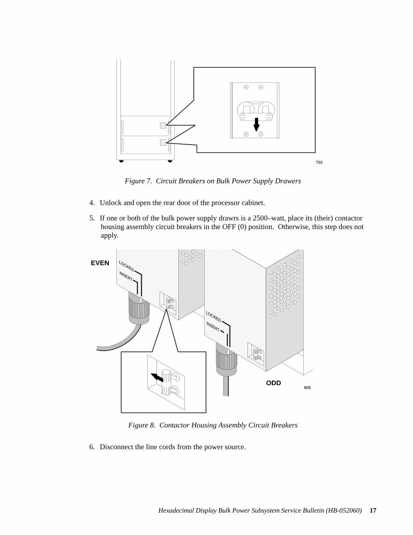
17Hexadecimal Display Bulk Power Subsystem Service Bulletin (HB-052060)
���
Figure 7. Circuit Breakers on Bulk Power Supply Drawers
4. Unlock and open the rear door of the processor cabinet.
5. If one or both of the bulk power supply drawrs is a 2500–watt, place its (their) contactorhousing assembly circuit breakers in the OFF (0) position. Otherwise, this step does notapply.
���ODD
EVEN
Figure 8. Contactor Housing Assembly Circuit Breakers
6. Disconnect the line cords from the power source.

18 Hexadecimal Display Bulk Power Supply Subsystem Service Bulletin (HB-052060)
8.2 Restart
The following is the module restart procedure.
1. Connect the ac line cords at the power source.
2. If one or both of the bulk power supply drawers is a 2500–watt, place its (their) contactorhousing assembly circuit breaker(s) in the ON (1) position. (See Figure 9.) The circuitbreakers are located at the rear of the main cabinet. Otherwise, this step does not apply.
���ODD
EVEN
Figure 9. Contactor Housing Assembly Circuit Breakers
3. At the front of the main cabinet, place the bulk power supply drawer circuit breakers in theON position.
4. Perform the step(s) below which apply to the type of control panel that is used on the mod-ule.
Module Control Unit Control Panel
Press the CYCLE switch on the module control panel until the AUTOBOOT option isdisplayed.
Press the ENTER switch immediately to execute the AUTOBOOT option.
LCD Control Panel
At the right side of the control panel, press the AUTO START UP switch.
On both types of control panels, the green OPERATING light alternates with the amberTEST/PROBLEM light every four seconds until the operating system starts.
5. Close the front and rear doors of the main cabinet.

19Hexadecimal Display Bulk Power Subsystem Service Bulletin (HB-052060)
9. Removal and Replacement ProceduresThis section contains the removal and replacement procedures for the bulk power supply drawers, theupper power backplane and fuses, and the lower power backplane and fuses.
9.1 Bulk Power Supply Drawers
9.1.1 Removal
Prior to removing and replacing a single bulk power supply drawer, only the following two prelimi-nary steps are required.
1. Unlock and open the front door of the processor cabinet.
2. Turn off the circuit breaker on the defective bulk power supply drawer. (See Figure 10.)Wait 40 seconds before proceeding to Step 3.
WARNING: There is a 40–second delay between the time that the circuit breaker isturned off and the power supply fans stop moving.
���
Figure 10. Circuit Breakers on Bulk Power Supply Drawer
3. Squeeze the trigger on the handles at each side of the bulk power supply drawer to releasethe locking levers. (See Figure 11.)

20 Hexadecimal Display Bulk Power Supply Subsystem Service Bulletin (HB-052060)
���
Triggers (2)
Locking Levers (2)
Figure 11. Triggers and Locking Levers on Bulk Power Supply Drawer
4. Pull out (approximately halfway ) the bulk power supply drawer until the safety latches onboth support rails engage.
5. Close the locking levers on the bulk power supply drawer.
WARNING: Each bulk power supply drawer weights 65 lbs (30 kg). To avoid per-sonal injury and/or equipment damage, make sure that two people are on hand to per-form the next step.
6. With one person positioned on each side of the bulk power supply drawer, press the safetylatches and pull out the bulk power supply drawer an additional two inches from the cabi-net. This ensures that the bulk power supply drawer is released. (See Figure 12.)

21Hexadecimal Display Bulk Power Subsystem Service Bulletin (HB-052060)
Safety Latches
���
Figure 12. Bulk Power Supply Drawer Safety Latches
WARNING: To prevent personal injury and possible equipment damage, use extremecaution when performing Step 7.
7. Grasp the bulk power supply drawer and pull it out of the cabinet.
CAUTION: To avoid damage, do not stand the power supply drawer on its connec-tors.
9.1.2 Replacement
To replace the bulk power supply drawer, reverse the removal steps. Once the replacement bulk pow-er supply drawer has been installed, watch for status code 1 on the drawer, followed by steady dis-play of status code 0. Status code 1 indicates battery charging. Status code 0 indicates normal opera-tion.
NOTE: If the replacement bulk power supply drawer does not power up, press theAUTO START UP switch. This supplies the START signal to the bulk power supplydrawer.

22 Hexadecimal Display Bulk Power Supply Subsystem Service Bulletin (HB-052060)
9.2 Upper Power Backplane and Upper Power Backplane Fuses
This section describes the removal and replacement procedures for the upper power backplane and itsfuses.
WARNING: When removing and replacing either the upper power backplane card orany of the fuses on it card, the module must first be entirely powered down.
9.2.1 Upper Power Backplane Removal and Replacement
To remove and replace the upper power backplane card, perform the following steps.
1. Perform the orderly power–down procedure. (Refer to Section 8.)
WARNING: To prevent personal injury, be sure to perform the entire orderly power–down procedure, including disconnection of the power line cords. Note that if the linecords are not disconnected, power is still applied to the module.
2. Open the IOA chassis and filler panels.
3. Remove the power section cover.
4. Label and disconnect the cables connected to the upper power backplane card. (Refer toTable 14.)
Table 14. Upper Power Backplane Card Connections
Connector Number Cable
J1 C–cable
J2 Bulk power supply drawer
J3 Bulk power supply drawer
J4 Transfomer fans (when implemented)
J5 Sequencer cable
J7 Chassis fans
J10 Transformer fans
J21 ODD wire harness fans
J22 EVEN wire harness fans
5. Pull the upper bulk power supply drawer approximately two inches away from the cabinet.
6. Remove the five screws that secure the upper power backplane card to the cabinet. (SeeFigure 13.)

23Hexadecimal Display Bulk Power Subsystem Service Bulletin (HB-052060)
��
� �
�
��� ��
�
��
�
Screw
Screws (2)Screws (2)
Figure 13. Upper Power Backplane Card
CAUTION: When removing the last screw fom the card, hold the card to prevent itfrom dropping.
To replace the upper power backplane card, reverse the removal steps.
9.2.2 Fuse Removal and Replacement on Upper Power Backplane Card
To remove and replace a fuse on the upper power backplane card, perform the following steps.
1. Perform the orderly power–down procedure. (Refer to Section 8.) STRESS–Also removeline cord.
WARNING: To prevent personal injury, be sure to perform the entire orderly power–down procedure, including disconnection of the power line cords. Note that if the linecords are not disconnected, power is still applied to the module.
2. Open the IOA chassis and filler panels at the rear of the main cabinet to access the powersection cover.
3. Remove the power section cover.
4. Perform the module restart procedure. (Refer to Section 8.)
5. Check the LEDs on the upper power backplane card. Note which fuse is adjacent to theLED that is OFF. (See Figure 14.)
6. Perform the orderly power–down procedure. (Refer to Section 8.)
WARNING: To prevent personal injury, be sure to perform the entire orderly power–down procedure, including disconnection of the power line cords. Note that if the linecords are not disconnected, power is still applied to the module.

24 Hexadecimal Display Bulk Power Supply Subsystem Service Bulletin (HB-052060)
7. On the upper power backplane card, remove the fuse whose location you noted in step 5.
��
� �
�
��� ��
�
��
�
LEDs (3)Fuses (3)
Figure 14. Fuses and LEDs on Upper Power Backplane Card
8. Snap in the replacement fuse on the upper power backplane card.
9. Replace the assemblies you removed from the module.
10. Perform the module restart procedure. (Refer to Section 8.)
9.3 Lower Power Backplane Card and Fuses
WARNING: When removing and replacing the lower power backplane card or any ofthe fuses on it, the module must first be entirely powered down.
This section outlines the removal and replacement procedures for the lower power backplane cardand its fuses
9.3.1 Lower Power Backplane Card
To remove and replace the lower power backplane card, perform the following procedure.
1. Perform the orderly power–down procedure. (Refer to Section 8.)
WARNING: To prevent personal injury, be sure to perform the entire orderly power–down procedure, including disconnection of the power line cords. Note that if the linecords are not disconnected, power is still applied to the module.
2. Unlock and open the processor cabinet’s rear door.
3. Open the IOA chassis and filler panels.
4. Remove the power section cover.
5. Label and disconnect the cables connected to the lower power backplane card. (Refer to thefollowing table.)
25Hexadecimal Display Bulk Power Subsystem Service Bulletin (HB-052060)
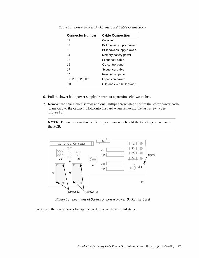
Table 15. Lower Power Backplane Card Cable Connections
Connector Number Cable Connection
J1 C–cable
J2 Bulk power supply drawer
J3 Bulk power supply drawer
J4 Memory battery power
J5 Sequencer cable
J6 Old control panel
J7 Sequencer cable
J8 New control panel
J9, J10, J12, J13 Expansion power
J11 Odd and even bulk power
6. Pull the lower bulk power supply drawer out approximately two inches.
7. Remove the four slotted screws and one Phillips screw which secure the lower power back-plane card to the cabinet. Hold onto the card when removing the last screw. (SeeFigure 15.)
NOTE: Do not remove the four Phillips screws which hold the floating connectors tothe PCB.
���
J1 – CPU C–ConnectorJ4
F1
F3
F4
J11
J9
J12
J10
J13
J7
J6J8
J5
J2 J3
F2
Screw
Screws (2) Screws (2)
Figure 15. Locations of Screws on Lower Power Backplane Card
To replace the lower power backplane card, reverse the removal steps.

26 Hexadecimal Display Bulk Power Supply Subsystem Service Bulletin (HB-052060)
9.3.2 Lower Power Backplane Card Fuse Removal and Replacement
To remove and replace a fuse on the upper power backplane card, perform the following steps.
1. Perform the orderly power–down procedure. (Refer to Section 8.)
WARNING: To prevent personal injury, be sure to perform the entire orderly power–down procedure, including disconnection of the power line cords. Note that if the linecords are not disconnected, power is still applied to the module.
2. Open the IOA chassis and filler panels at the rear of the main cabinet to access the powersection cover.
3. Remove the power section cover.
4. Perform the module restart procedure. (Refer to Section 8.)
5. Check the LEDs on the lower power backplane card. Note which fuse is adjacent to theLED that is OFF. (See Figure 16.)
���
J1 – CPU C–ConnectorJ4
F1
F3
F4
J11
J9
J12
J10
J13
J7
J6J8
J5
J2 J3
F2
LEDs (4)
Fuses (4)
Figure 16. Fuses and LEDs on Lower Power Backplane Card
6. Perform the orderly power–down procedure. (Refer to Section 8.)
WARNING: To avoid personal injury, be sure to perform the orderly power–downprocedure in it entirety, including power line cord disconnection. Note that if moduleline cords are not disconnected, power is still applied to the module.
7. Remove the fuse whose location you noted in Step 5.
8. Snap in the replacement fuse on the lower power backplane card.
9. Replace the assemblies you removed from the module.
10. Perform the module restart procedure. (Refer to Section 8.)

A–1Hexadecimal Display Bulk Power Supply Subsystem Service Bulletin (HB–052060)
10. AppendixThis section contains block diagrams of the hexadecimal display bulk power supply drawer and itscontroller board.

A–2
He
xad
ecim
al D
ispla
y Bu
lk Po
we
r Su
pp
ly Su
bsyste
m S
ervice
Bu
lletin
(HB
–0
52
06
0)
Figure A–1. Hexadecimal Display Bulk Power Supply Drawer Block Diagram
AP–E2230–X Hex Bulk ControllerAP–E21202Hex Display
See schematicDS–EE21202
AW–000151
Chassis Gnd
Fan SenseAC SenseDC SenseBulk PowerBattery PowerShuntLow Voltage ACRelay Control+24V
A
Switched AC Output AS–E22201–X Cap BoardSee Schematic DS–E22201
FF–000009
Fan Power
Battery Power
Battery Control
Bulk Rtn
Shunt
Bulk Rtn
AS–E21010DC Fan Assy
Fan PowerFan Sense
AW–0010105
AW–0010105
RJ050A5 Ohms225 Watts
AW–000745
AW–000813
24 VAC Input
24 VAC Input
+24 VAC Output (+Bulk)
–24VDC Output (Bulk Rtn)
AC Input
Relay Switched AC Output18 AmpCircuit Breaker
208/240 VAC
AW–0100105
AC Input208/240 VAC
AW–000747
4321
AC Sense
DC Sense
Bulk Power
Battery Power
Battery Control
Shunt
Low Voltage AC
Relay Control
+24V
Part of AS–E22201 Board Assy
AW–000742 AW–000746
AW–000342–01
��
FF–ANI 150
150 Amp Fuse
AW–010105
JR–0004PWR–R
AW–000734
AW–000748
AW–000735
AW–000737
BCDYccGnd
BA–000011
12V 9AH Battery
BA–00001112V 9A Batery
09–BSU101
AS–E22230–X BULK DRAWER ASSEMBLY BLOCK DIAGRAM

A–3
He
xad
ecim
al D
ispla
y Bu
lk Po
we
r Su
pp
ly Su
bsyste
m S
ervice
Bu
lletin
(HB
–0
52
06
0)
Figure A–2. Hexadecimal Display Bulk Power Supply Controller Block Diagram
GndGnd
P
Xfmr/Sec+
Xfmr/Sec
Xfmr/Sec–
VNR
RAW
+Bulk
+Bulk
J013–17
J013–18
Mem Bat
09–000001
Chg Pwr
75W Boost Conv.
+24V
All Pwr
+Bulk
P
+5V
+12V
+24V
+34V
All Pwr
AnalogControl/Sense
Circuits
Logic/State Machine
PowerFailProtectiveCircuitry
Opt
o Is
olat
ion
J002–1 Test from CPU
+5V
Charger Off
Mem Bat
+ Bulk
Battery SenseCircuit
Chg Pwr
J002–2 CPU Kill Batt
J002–6 Sys Red Light
J002–10 AC Fail
09–IRF541
Vref
+34VPS
+Bulk
Mem Bat
+24
V
J013
–5
J003
–4
+Bulk
Plane
J003
–19
Fan
Gnd
J003
–15
Fan
+12
V
Nex
tC
ab G
nd
Nex
tC
ab +
12V
+24V RegLM317T
+12V Reg78M12
+12V Reg78M12
+12V
J002–25 Sys Green Lt
J002–7 CPU Gnd
J002–12 CPU Gnd
J002–13 CPU Gnd
Pnl Green Lt
J002–14 CPU Gnd
J002–15 CPU Gnd
J003–12 CPU +5V
AC Sense
DC Sense
Start/Stop
Tone
LM723
+34V 2.2A/29.5V Batt Charg/Reg
FE
T G
ate
J013
–6
AC
S
ense
B J
013–
4
Gnd
J01
3–3
AC
Sen
se A
J0
13–3
Rel
ay J
013–
1
Gnd
J01
4–4
+5V
J014
–2
J013–8 DC Bulk Sense
J003–25 Dwr Out
J003–24 Gnd
J003–10 Fan Mod OK –
J003–6 Next Cab ON
J003–5
ResetClock
Shunt2.5V Ref
5V Ref
Hex Display Control
+5V Buck Conv+5V
LMM
2575
.+Bulk
J013–12J013–13
TL494Ctrl
09–IRF54
J013
–19
+B
AT
J013
–20
+B
at
J003
–1 B
at O
ut
J003
–2 B
at O
ut
J003
–7 C
om B
at
J013–11
J013–14
J013–10
Shu
nt
Shu
nt
Res
isto
r
Res
isto
rJ0
13–1
5J0
13–1
6
Fan OK
Battery OK
Shutdown B–
Shutdown A–
J002–17
J003–9
J002–8 Battery Lasted
START
STOPJ002–18
J002–22J002–23
Next Cab START
Fb
BA
T S
EN
SE
HI B
AT
J003
–20
BA
T L
IGH
T
CT
+5VPS
Fb
+5V
Charger Off
Dat
a J0
14 1
, 3, 5
, 6
09–I
RF
541
J013–9 DC Bulk Sense
Vsource to 1413 I.C.s
Plane
Plane


USER’S COMMENT FORM
Hexadecimal Display Bulk Power SubsystemService Bulletin
HB–052060
If you prefer to use the comment on manual utility, refer to the preface for instructions.
What chapters/sections did you find most useful?
What improvements would you like to see in the next revision of this manual?
Did you find any errors in this manual? If so, please specify by page.
Address:
From: Job Title:
Business Phone: Date:
StratusCustomer ServiceDocumentation

Stratus Computer Inc.Customer Service Documentation Dept.Mail Stop M2–2–CCS55 Fairbanks Blvd.Marlboro, MA 01752 – 1298
fold
fold
Tape edge; do not staple.
Tape edge; do not staple.
Postage


HB–052060
Stratus Computer, Inc.55 Fairbanks BoulevardMarlboro, MA 01752–1298


