PSR-1A PSR-1A Position Sensing Cylinders 60 HG PSR-1A Position Sensing Cylinders PSR-1A 61 HG General Purpose Type Port G thread type (only for SD style) ●For a port G thread type cylinder, specify the code as following. (Example) PSR-1A 6SD40N50TG Lock nut number for ordering Port G thread type Note) The port G thread has dimensions different from the standard dimensions depending on the bore. Refer to the dimensional drawing. Air vent specifications (order made) The air vents are laid on the port surface and located symmetrical positions to the ports. Symbol Bore d B C h Note) When making an order only for the lock nut, indicate the part number. Dimensional Table f32 f40 f50 f63 f80 f100 f125 LNH-16F-H LNH-20F-H LNH-24F-H LNH-30F-H LNH-39F-H LNH-48F-H LNH-64F-H 22 27 32 41 55 70 90 M16 ×1.5 M20 ×1.5 M24 ×1.5 M30 ×1.5 M39 ×1.5 M48 ×1.5 M64 ×2 25.4 31.2 37.0 47.3 63.5 80.8 104 10 12 14 17 20 26 35 Unit: mm Set screw (Exclusive use for air vent) Steel ball (Air vent structure) 2-air vents 2-ports h B C d The item enclosed by broken line needs not to be entered, if unnecessary. Semi-standard Part number ●Standard type PSR-1A - - G V L SD 6 40 N 50 T 3 6 Fluorocarbon HNBR No cushion Cylinder stroke (mm) 5, 10, 15, 20, 25, 30, 35, 40, 45, 50 mm Note) For strokes other than the above standard strokes, contact us. SD FA LA Basic style Rod flange Foot type None G Rc thread G thread Note) When ordering the FA style cylinder body, it is necessary to change dimension WF of the SD style cylinder. For details, contact us. Note) G thread is applicable only to the SD style. None L Without lock nut With one lock nut Note) If two or more lock nuts are required, make an order for the additional lock nut(s). None V [None] Without air vent (standard) With air vents (order made: f32 to f125) SD:f32 to f125 FA:f32 to f80 LA:f32 to f63 Male thread type Type❶ Thread type❼ Cylinder bore❹ Stroke❻ Lock nut❾ Air vent type1 Port type❽ Seal material❷ Mounting style❸ Cushioning❺ Calculation formula Cylinder weight (kg)=basic weight+(cylinder stroke (mm)×additional weight per mm of stroke) Calculation example PSR-1A, SD style, bore f50, cylinder stroke 50 mm 2.7+(50×0.037)=4.55kg Weight Table f32 f40 f50 f63 f80 f100 f125 1.5 1.9 2.7 4.2 7.4 14.0 24.7 0.025 0.030 0.037 0.047 0.067 0.102 0.152 0.025 0.030 0.037 0.047 0.067 - - 0.027 0.034 0.044 0.062 - - - Bore (mm) Basic style (SD) Flange type (FA) Foot type (LA) Basic weight Basic weight Basic weight Amplifier weight Additional weight per mm of stroke Additional weight per mm of stroke Additional weight per mm of stroke 2.1 3.1 4.3 6.3 11.2 - - 1.5 1.9 2.8 4.5 - - - 0.05 Unit: kg Bore (mm) Cylinder stroke (mm) f32 f40 f50 f63 f80 f100 f125 5 ○ ○ ○ ○ ○ ○ ○ ○ ○ ○ ○ ○ ○ ○ ○ ○ ○ ○ ○ ○ ○ ○ ○ ○ ○ ○ ○ ○ ○ ○ ○ ○ ○ ○ ○ ○ ○ ○ ○ ○ ○ ○ ○ ○ ○ ○ ○ ○ ○ ○ ○ ○ ○ ○ ○ ○ ○ ○ ○ ○ ○ ○ ○ ○ ○ ○ ○ ○ ○ ○ 10 15 20 25 30 35 40 45 50 Note) For strokes of more than 60 mm, contact us. Standard Stroke Range Bore (mm) Rod dia. (mm) Double acting single rod f32 f40 f50 f63 f80 f100 f125 f18 f22 f28 f36 f45 f56 f70 Extension side Retraction side Piston Pressure Receiving Area Table 804 1257 1963 3117 5027 7854 12272 550 876 1348 2100 3436 5391 8424 Unit: mm² Calculation formula F=A×P×b(N) F: cylinder force (N) A: piston pressure receiving area (mm²) P: working pressure (MPa) b: load rate Calculation example Double acting single rod, bore f40, working pressure: 16 MPa, load rate: 0.8 Cylinder force on extension side (N) =1257×16×0.8=16090(N) Cylinder force on retraction side (N) =876×16×0.8=11213(N) 16 MPa Position Sensing Compact Hydraulic Cylinder 16 MPa Position Sensing Compact Hydraulic Cylinder ● How to order
Transcript
PSR-1APSR-1A Position Sensing Cylinders
60HG
PSR-1APosition S
ensing Cylinders
PSR-1A
61HG
General Purpose Type
Port G thread type (only for SD style)●For a port G thread type cylinder, specifythe code as following.(Example)
PSR-1A 6SD40N50TG
Lock nut number for ordering
Port G thread type
Note) The port G thread has dimensions differentfrom the standard dimensions depending onthe bore. Refer to the dimensional drawing.
Air vent specifications (order made)The air vents are laid on the port surface andlocated symmetrical positions to the ports.
Symbol
Bored B C h
Note) When making an order only for the lock nut,indicate the part number.
Dimensional Table
f32
f40
f50
f63
f80
f100
f125
LNH-16F-H
LNH-20F-H
LNH-24F-H
LNH-30F-H
LNH-39F-H
LNH-48F-H
LNH-64F-H
22
27
32
41
55
70
90
M16×1.5
M20×1.5
M24×1.5
M30×1.5
M39×1.5
M48×1.5
M64×2
25.4
31.2
37.0
47.3
63.5
80.8
104
10
12
14
17
20
26
35
Unit: mm
Set screw(Exclusive use for air vent)
Steel ball
(Air vent structure)
2-air vents
2-ports
h B
C
d
The item enclosed by broken line needs not to be entered, if unnecessary. Semi-standard
Part number
●Standard type PSR-1A --G VLSD6 40 N 50 T
36FluorocarbonHNBR
No cushion
Cylinder stroke (mm)5, 10, 15, 20, 25, 30, 35, 40, 45, 50 mmNote) For strokes other than the above standard
strokes, contact us.
SDFALA
Basic styleRod flangeFoot type
NoneG
Rc threadG thread
Note) When ordering the FA style cylinder body, it is necessary to change dimension WF of the SD style cylinder. For details, contact us.
Note) G thread is applicable only to the SD style.
NoneL
Without lock nutWith one lock nut
Note) If two or more lock nuts are required, make an order for the additional lock nut(s).
NoneV
[None] Without air vent (standard)With air vents(order made: f32 to f125)
SD:f32 to f125FA:f32 to f80LA:f32 to f63
Male thread type
Type❶
Thread type❼
Cylinder bore❹
Stroke❻
Lock nut❾
Air vent type10
Port type❽
Seal material❷
Mounting style❸
Cushioning❺
Calculation formula Cylinder weight (kg)=basic weight+(cylinder stroke (mm)×additional weight per mm of stroke)Calculation example PSR-1A, SD style, bore f50, cylinder stroke 50 mm
2.7+(50×0.037)=4.55kg
Weight Table
f32
f40
f50
f63
f80
f100
f125
1.5
1.9
2.7
4.2
7.4
14.0
24.7
0.025
0.030
0.037
0.047
0.067
0.102
0.152
0.025
0.030
0.037
0.047
0.067
-
-
0.027
0.034
0.044
0.062
-
-
-
Bore(mm)
Basic style (SD) Flange type (FA) Foot type (LA)
Basicweight
Basicweight
Basicweight
AmplifierweightAdditional weight
per mm of strokeAdditional weightper mm of stroke
Additional weightper mm of stroke
2.1
3.1
4.3
6.3
11.2
-
-
1.5
1.9
2.8
4.5
-
-
-
0.05
Unit: kg
Bore(mm)
Cylinder stroke (mm)
f32
f40
f50
f63
f80
f100
f125
5
○
○
○
○
○
○
○
○
○
○
○
○
○
○
○
○
○
○
○
○
○
○
○
○
○
○
○
○
○
○
○
○
○
○
○
○
○
○
○
○
○
○
○
○
○
○
○
○
○
○
○
○
○
○
○
○
○
○
○
○
○
○
○
○
○
○
○
○
○
○
10 15 20 25 30 35 40 45 50
Note) For strokes of more than 60 mm, contact us.
Standard Stroke Range
Bore(mm)
Rod dia.(mm)
Double acting single rod
f32
f40
f50
f63
f80
f100
f125
f18
f22
f28
f36
f45
f56
f70
Extension side Retraction side
Piston Pressure Receiving Area Table
804
1257
1963
3117
5027
7854
12272
550
876
1348
2100
3436
5391
8424
Unit: mm²Calculation formula F=A×P×b(N)F: cylinder force (N)A: piston pressure receiving area (mm²)P: working pressure (MPa) b: load rate
Calculation exampleDouble acting single rod, bore f40,working pressure: 16 MPa, load rate: 0.8Cylinder force on extension side (N)=1257×16×0.8=16090(N)Cylinder force on retraction side (N)=876×16×0.8=11213(N)
16 MPa Position Sensing Compact Hydraulic Cylinder
16 MPa Position Sensing Compact Hydraulic Cylinder
● How to order
PSR-1APSR-1A Position Sensing Cylinders
62HG
PSR-1APosition S
ensing Cylinders
PSR-1A
63HG
Standard Specifications
±999999
24 V DC ±10%
0 to 50℃ (No freezing)
35 to 80%RH (No condensing)
P-UC-APCQP
Phase AB
-
200 kHz
-
Analog Pulse
Stroke×1/10000
Analog voltage/analog current
A-UC-APCQP
1 kHz
±0.02%FS
Voltage output Note) Line driver output
1000 times/sec
10 times/sec
Display by fluorescent display tube
No-voltage input (reed sensor/solid state sensor)
Open collector Max. rating: 50 V DC, 50 mA(Provided with multi-point output function (5 points) to enable to individually set the upper and lower limits and pulse position correcting function)
Voltage input 0 to 10 VVoltage input 1 to 5 V
Current input 4 to 20 mA
Open collector inputDifferential input (line driver input)
12 V voltage input24 V voltage input
Type
Model number
Applicable input signals
Display range
Resolution
Reply frequency
Linearity
Monitor output
Sampling speed
Display speed
Display method
Control input
Power supply voltage
Ambient temperature
Ambient humidity
Signals
Control output
Note) The monitor output at current input (4 to 20 mA) is voltage output of 1 to 5 V.
Type Analog input Pulse input
Display of positionBank switching
Multi-point outputPositional data hold
Display of positionBank switching
Multi-point outputPositional data hold
0 setting signalCorrecting function
Modelnumber
Functions
A-A-UC-APCQPV-A-UC-APCQP
-
- -
21-P-UC-APCQP42-P-UC-APCQP00-P-UC-APCQP
Function TableSeries Detection method
Absolute method
Linear pulse encoder Encoder type
Analog type (1 to 5 V)
Analog type(4 to 20 mA, 0 to 10 V)
Signal type
List of Applicable Actuators
Note) For the details of each cylinder, see the sectionof each series.
B1-NTPB1-HTPB1-TTPA1-RSP
3-P538-P078-P041
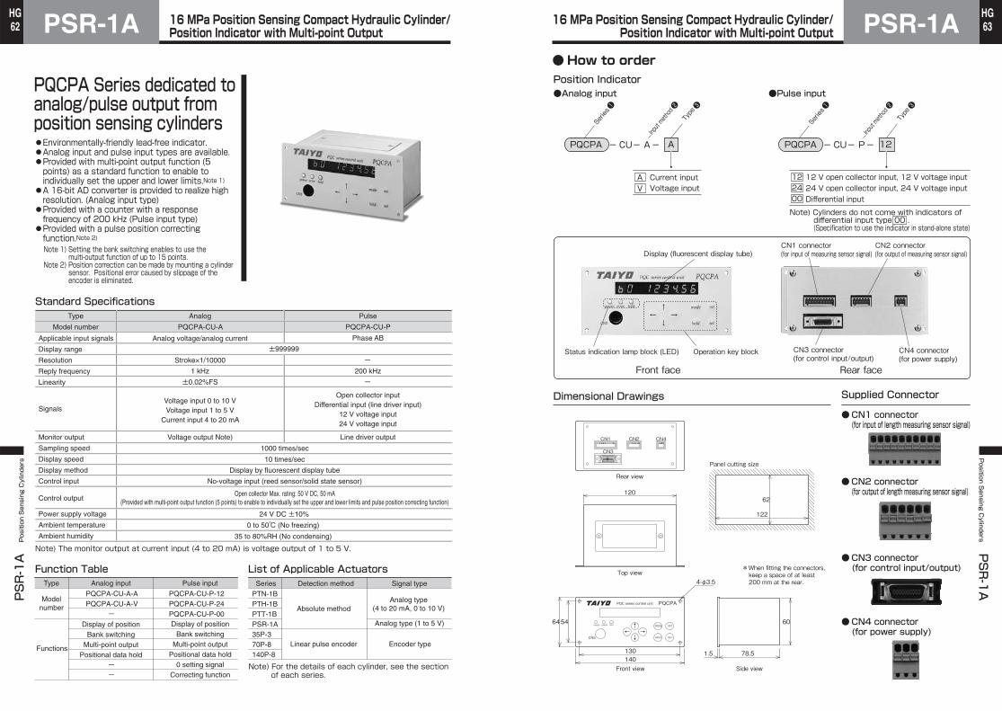
PQCPA Series dedicated toanalog/pulse output from position sensing cylinders●Environmentally-friendly lead-free indicator.●Analog input and pulse input types are available.●Provided with multi-point output function (5 points) as a standard function to enable to individually set the upper and lower limits.Note 1)●A 16-bit AD converter is provided to realize high resolution. (Analog input type)●Provided with a counter with a response frequency of 200 kHz (Pulse input type)●Provided with a pulse position correcting function.Note 2)Note 1) Setting the bank switching enables to use the
multi-output function of up to 15 points.Note 2) Position correction can be made by mounting a cylinder
sensor. Positional error caused by slippage of the encoder is eliminated.
Position Indicator●Analog input
APCQP - AUC -- A
AVCurrent inputVoltage input
Series❶
Input method ❷
Type❸
Series❶
Input method ❷
Type❸
●Pulse input
APCQP - 21UC -- P
214200
12 V open collector input, 12 V voltage input24 V open collector input, 24 V voltage inputDifferential input
Note) Cylinders do not come with indicators ofdifferential input type 00 . (Specification to use the indicator in stand-alone state)
Dimensional Drawings Supplied Connector
CN1 connector(for input of length measuring sensor signal)
●
CN4 connector(for power supply)
●
CN2 connector(for output of length measuring sensor signal)
●
CN3 connector(for control input/output)
●
Front face Rear face
CN5 HOLD
MODE
SET
RST
→↓
←↑ERROR HOLDPOWER
PQC series control unit PQCPA
Front view
Rear view
Top view
Side view
Panel cutting size
64
140
60
78.51.5
62
122
4-φ3.5
CN1 CN2 CN4
CN3
130
54
120
*When fitting the connectors,keep a space of at least200 mm at the rear.
Display (fluorescent display tube)
Status indication lamp block (LED) Operation key block
CN1 connector(for input of measuring sensor signal)
CN2 connector(for output of measuring sensor signal)
CN3 connector(for control input/output)
CN4 connector(for power supply)
16 MPa Position Sensing Compact Hydraulic Cylinder/Position Indicator with Multi-point Output
16 MPa Position Sensing Compact Hydraulic Cylinder/Position Indicator with Multi-point Output
● How to order
KO837450
Discontinued(白)
KO837450
Discontinued(白)
PSR-1APSR-1A Position Sensing Cylinders
64HG
PSR-1APosition S
ensing Cylinders
PSR-1A
65HG
PQCPA - 01CV1
PQCPA - IO
-
010510
1m5m10m
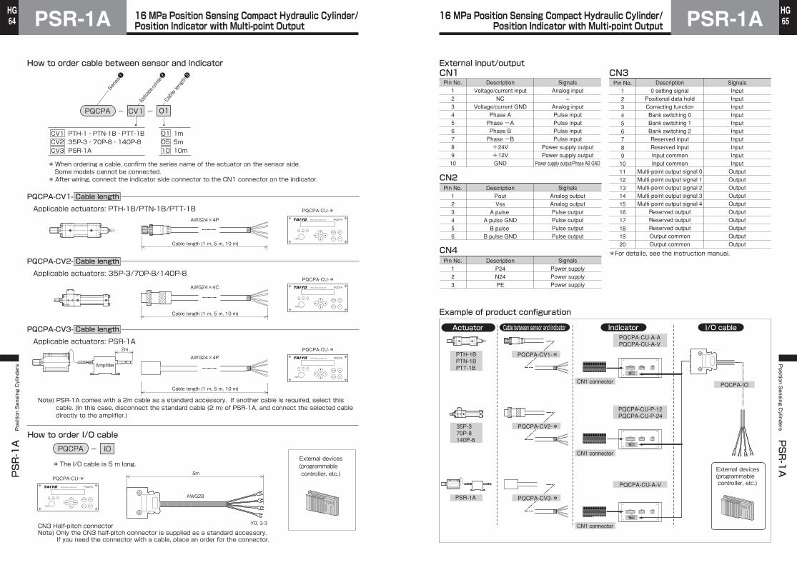
How to order cable between sensor and indicator
* When ordering a cable, confirm the series name of the actuator on the sensor side.Some models cannot be connected.
* After wiring, connect the indicator side connector to the CN1 connector on the indicator.
Applicable actuators: PTH-1B/PTN-1B/PTT-1B
Applicable actuators: 35P-3/70P-8/140P-8
Applicable actuators: PSR-1A
CN3 Half-pitch connectorNote) Only the CN3 half-pitch connector is supplied as a standard accessory.
If you need the connector with a cable, place an order for the connector.
How to order I/O cable
* The I/O cable is 5 m long.External devices(programmable controller, etc.)
CV1CV2CV3
PTH-1・PTN-1B・PTT-1B35P-3・70P-8・140P-8PSR-1A
Series❶
Applicable cylinder❷
Cable length❸
PQCPA-CV1- Cable length
PQCPA-CV2- Cable length
PQCPA-CV3- Cable length
CN5 HOLD
MODE
SET
RST
→↓
←↑ERROR HOLDPOWER
PQC series control unit PQCPA
PQCPA-CU-*
CN5 HOLD
MODE
SET
RST
→↓
←↑ERROR HOLDPOWER
PQC series control unit PQCPA
PQCPA-CU-*
Cable length (1 m, 5 m, 10 m)
Cable length (1 m, 5 m, 10 m)
Cable length (1 m, 5 m, 10 m)
Amplifier
AWG24×4C
AWG24×4P
AWG28
Y0, 3-3
2m
AWG24×4P
CN5 HOLD
MODE
SET
RST
→↓
←↑ERROR HOLDPOWER
PQC series control unit PQCPA
PQCPA-CU-*
5m
CN5 HOLD
MODE
SET
RST
→↓
←↑ERROR HOLDPOWER
PQC series control unit PQCPA
PQCPA-CU-*
Note) PSR-1A comes with a 2m cable as a standard accessory. If another cable is required, select this cable. (In this case, disconnect the standard cable (2 m) of PSR-1A, and connect the selected cable directly to the amplifier.)
Actuator Cable between sensor and indicator Indicator I/O cable
16 MPa Position Sensing Compact Hydraulic Cylinder/Position Indicator with Multi-point Output
16 MPa Position Sensing Compact Hydraulic Cylinder/Position Indicator with Multi-point Output
KO837450
Discontinued(白)
KO837450
Discontinued(白)
PSR-1APSR-1A Position Sensing Cylinders
66HG
PSR-1APosition S
ensing Cylinders
PSR-1A
67HG
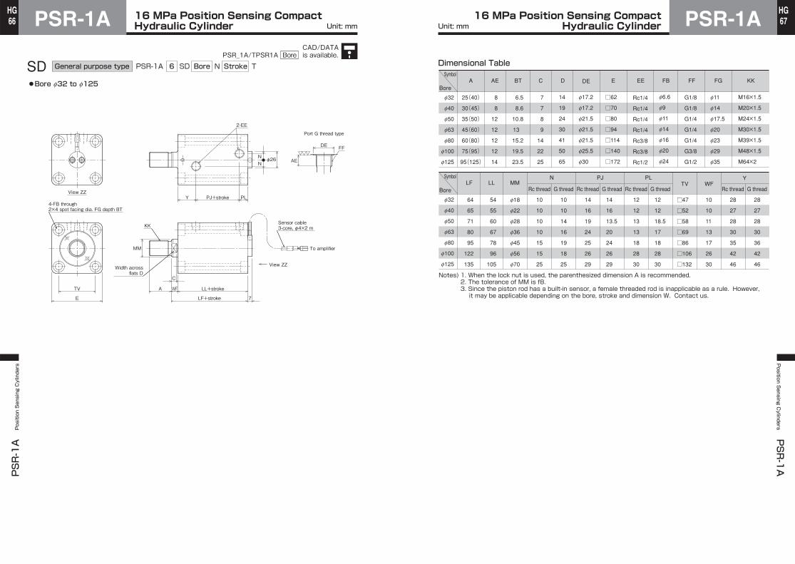
SD TPSR-1A StrokeGeneral purpose type Bore6
●Bore f32 to f125
View ZZ
View ZZ
To amplifier
WF LL+stroke
C
A
LF+stroke
Width acrossflats D
MM
KK
TV
E
4-FB through2×4 spot facing dia. FG depth BT
Sensor cable3-core, φ4×2 m
7
Y PJ+stroke PL
NN
2-EE
φ26
DE
AE
FF
Port G thread type
SD N Dimensional Table
f32
f40
f50
f63
f80
f100
f125
Symbol
Bore
f32
f40
f50
f63
f80
f100
f125
A AE BT C D E EE FB FF FG KKDE
25(40)
30(45)
35(50)
45(60)
60(80)
75(95)
95(125)
8
8
12
12
12
12
14
6.5
8.6
10.8
13
15.2
19.5
23.5
7
7
8
9
14
22
25
14
19
24
30
41
50
65
f17.2
f17.2
f21.5
f21.5
f21.5
f25.5
f30
□62
□70
□80
□94
□114
□140
□172
Rc1/4
Rc1/4
Rc1/4
Rc1/4
Rc3/8
Rc3/8
Rc1/2
f6.6
f9
f11
f14
f16
f20
f24
G1/8
G1/8
G1/4
G1/4
G1/4
G3/8
G1/2
f11
f14
f17.5
f20
f23
f29
f35
M16×1.5
M20×1.5
M24×1.5
M30×1.5
M39×1.5
M48×1.5
M64×2
LF LL MMRc thread
N PJ PL
G thread Rc thread G thread Rc thread G thread Rc thread G threadTV WF
Y
64
65
71
80
95
122
135
54
55
60
67
78
96
105
10
10
10
10
15
15
25
10
10
14
16
19
18
25
14
16
19
24
25
26
29
14
16
13.5
20
24
26
29
12
12
13
13
18
28
30
12
12
18.5
17
18
28
30
□47
□52
□58
□69
□86
□106
□132
10
10
11
13
17
26
30
28
27
28
30
35
42
46
28
27
28
30
36
42
46
f18
f22
f28
f36
f45
f56
f70
1. When the lock nut is used, the parenthesized dimension A is recommended.2. The tolerance of MM is f8.3. Since the piston rod has a built-in sensor, a female threaded rod is inapplicable as a rule. However,it may be applicable depending on the bore, stroke and dimension W. Contact us.
Notes)
Symbol
Bore
Unit: mm Unit: mm16 MPa Position Sensing Compact
Hydraulic Cylinder16 MPa Position Sensing Compact Hydraulic Cylinder
CAD/DATAis available.PSR_1A/TPSR1A Bore
PSR-1APSR-1A Position Sensing Cylinders
68HG
PSR-1APosition S
ensing Cylinders
PSR-1A
69HG
FA PSR-1A StrokeGeneral purpose type Bore6
●Bore f32 to f80
FE
View ZZ
To amplifierR MM
TF
UF
TV
E
W
C
A
Width acrossflats D
KK
F LL+stroke
LF+stroke
Y PJ+stroke PL
φ26
2-EE
NN
7
Sensor cable3-core, φ4×2 m
4-FB
4-M
View ZZ
FA N T Dimensional Table
f32
f40
f50
f63
f80
Symbol
Bore
f32
f40
f50
f63
f80
A C D E EE F FB FE KK LF
25(40)
30(45)
35(50)
45(60)
60(80)
7
7
8
9
14
14
19
24
30
41
15
20
20
20
25
62
70
85
98
118
79
85
91
100
120
□62
□70
□80
□94
□114
Rc1/4
Rc1/4
Rc1/4
Rc1/4
Rc3/8
f6.6
f11
f14
f14
f18
M16×1.5
M20×1.5
M24×1.5
M30×1.5
M39×1.5
LL M MM N PJ PL R TF TV UF W Y
54
55
60
67
78
M6×1
M8×1.25
M10×1.5
M12×1.75
M14×2
f18
f22
f28
f36
f45
10
10
10
10
15
14
16
19
24
25
12
12
13
13
18
40
46
58
65
87
80
96
108
124
154
□47
□52
□58
□69
□86
95
118
135
150
185
10
10
11
13
17
28
27
28
30
35
Symbol
Bore
1. When the lock nut is used, the parenthesized dimension A is recommended.2. The tolerance of MM is f8.3. Since the piston rod has a built-in sensor, a female threaded rod is inapplicable as a rule. However, it may be applicable depending on the bore, stroke and dimension W. Contact us.
Notes)
Unit: mm Unit: mm16 MPa Position Sensing Compact
Hydraulic Cylinder16 MPa Position Sensing Compact Hydraulic Cylinder
CAD/DATAis available.PSR_1A/TPSR1A Bore
PSR-1APSR-1A Position Sensing Cylinders
70HG
PSR-1APosition S
ensing Cylinders
PSR-1A
71HG
LH
EB MM To amplifier
View ZZ
SY SG+stroke SW
T
TSEA Y PJ+stroke PL
TX TW TZ+stroke
LL+strokeWF
CWidth across
flats D
4-GB through4-spot facing dia.FG depth BT
Sensor cable3-core, φ4×2 m
2-EE
A
KK
7
φ26NN
LF+stroke
View ZZ
LA PSR-1A StrokeGeneral purpose type Bore6
●Bore f32 to f63
LA N TSymbol
Bore
Symbol
Bore
f32
f40
f50
f63
f32
f40
f50
f63
A
25(40)
30(45)
35(50)
45(60)
EE
Rc1/4
Rc1/4
Rc1/4
Rc1/4
LH
25±0.06
29±0.06
34±0.06
42±0.06
KK
M16×1.5
M20×1.5
M24×1.5
M30×1.5
BT
8.6
10.8
13
15.2
C
7
7
8
9
D
14
19
24
30
EA
70
80
94
114
EB
56
64
74
89
FG
f14
f17.5
f20
f23
GB
f9
f11
f14
f16
LF
64
65
71
80
LL
54
55
60
67
MM
f18
f22
f28
f36
N
10
10
10
10
PJ
14
16
19
24
PL
12
12
13
13
SG
24
23
27
32
SW
10
12
13
15
SY
20
20
20
20
T
63
70
80
100
TS
56
62
74
90
TW
12
12
14
16
TX
28
28
29
31
TZ
14
15
17
20
WF
10
10
11
13
Y
28
27
28
30
Dimensional Table
1. When the lock nut is used, the parenthesized dimension A is recommended.2. The tolerance of MM is f8.3. Since the piston rod has a built-in sensor, a female threaded rod is inapplicable as a rule.However, it may be applicable depending on the bore, stroke and dimension W. Contact us.
Notes)
Bore
f32
f40
f50
f63
Nominal dimensionsof keyb×h×I
12×8×63(both rounded)
12×8×70(both rounded)
14×9×80(both rounded)
16×10×100(both rounded)
Key groove dimensions
b1
12
12
14
16
t1
5
5
5.5
6
r1
0.25 to 0.40+0.2 0
+0.2 0
+0.2 0
+0.2 0
0 -0.043
0 -0.043
0 -0.043
0 -0.043
Recommended key groove dimensions
Dimensional Table
When using a parallel key
When not using a parallel key
b1
r1 r1t1Parallel key attached to the cylinder
Pushing stopperPulling stopper
The stopper size must be the same as the attached parallel key size.
●When using the foot type, use the attached parallel key to install the cylinder, referring to the recommended key groove dimensions.●When not using the parallel key, attach the stoppers at the front and rear with respect to the cylinder stroke direction. If the cylinder is used without a key or stoppers, excessive force is applied to the cylinder mounting bolts, and the bolts may be damaged.
Unit: mm Unit: mm16 MPa Position Sensing Compact
Hydraulic Cylinder16 MPa Position Sensing Compact Hydraulic Cylinder
CAD/DATAis available.PSR_1A/TPSR1A Bore
PSR-1APSR-1A Position Sensing Cylinders
72HG
PSR-1APosition S
ensing Cylinders
PSR-1A
73HG
Amplifier
■Sensor output (3 patterns according to cylinder full stroke range)
OFFSET
SPAN
Sensor side
Connection
(Supplied)Power supply/output signal line, 4-core,2 m, with 4-pin connector on one end,other end as cut
Power supplyoutput side
70 2-φ4.8
23
Offset adjusting volume
35.2
4
48.5
58(11) (11)
80
Connector for sensorcable (3-pin)
Connector for power supply/output line (4-pin)
Span adjusting volume
DIN rail mounting groove
1-Brown: Power supply (+12 V to 24 V)2-Black: Power supply G3-Orange: Signal G4-Blue: Signal+
When the full stroke is 5, 10 or 15 mm
0 5 10 15
1
2
3
4
5
0
Retracting end
Output/length (V/mm)=0.27
Output voltage (V)
Output voltage (V)
Output voltage (V)
ST = 5
ST = 10
ST = 15
1 to 2.3V
1 to 3.7V
1 to 5V
Stroke (mm)
Note) ST=Stroke
3.7V
2.3V
Stroke (mm)ST = 20
1 to 4.3V
ST = 30
ST = 25
Output/length (V/mm)=0.13
1 to 3.7VRetracting end
3020100 5 15 25
When the full stroke is 20, 25, or 30 mm
1 to 5V
3.7V
4.3V
Output/length (V/mm)=0.08
0 10 20 302515Retracting end
1 to 3.8V
5
ST = 40
ST = 45
1 to 4.2V
1 to 5V
ST = 35Stroke (mm)
35 40 45 50
ST = 50
1 to 4.6V
4.6V
4.2V
3.8V
1
2
3
4
5
0
When the full stroke is 35, 40, 45, or 50 mm
1
2
3
4
5
0
1. The values shown above are for reference. The actual output may be slightly different.
2. The amplifier block has an offset adjusting screw and a span adjusting screw, so that an adjustment of about 5% can be made.
3. The output voltage at the same stroke may vary depending on the full stroke range.
(Example) The output voltage at a stroke of 5 mm on a cylinder with a full stroke of 15 mm differs from that at a stroke of 5 mm on a cylinder with a full stroke of 30 mm.
Notes)
Principle of sensor
Linearity
Influence of rotation of piston rod
Influence of cable
Combination of sensor and amplifier
Power supply voltage
Influence of deformation of cylinder body and piston rod
Temperature drift
Coil
Sensor
CylinderMetallictube
Difference
Position
FSRO
Sensor output
Ideal output
Actual output
Sensor surface temperature (℃)Difference from output at 25℃ (%FS) Example of temperature characteristics (φ40ST50)
Piston rodadvancing end
0 20 40 60 80 100
1086420-2
When a pulse signal is given to the coil, the pulse waveform shows not a regular form, but a form like a mound due to the inductance. If there is a metallic tube on the outside of the coil, the waveform changes further (the gradient becomes larger) under the influence of eddy current.This change to the waveform depends on the ratio of the area covered with the metallic tube. This sensor converts the ratio of the area covered with the metallic tube to a positionally correlated voltage.
If the cable length between the sensor and the amplifier is changed, the sensor output changes. Use the supplied cable without cutting or extending. The output obtained when the cable is in a coiled state may lightly differ from that when it is in a straight state.Lay the cable in such a way that it will not considerably change in state during use.
Since the amplifier has been adjusted according to the sensor, if the amplifier is combined with other sensor, normal output cannot be obtained. When using several sensors, make sure that each amplifier has the same serial number as that of the corresponding sensor.
The electric resistance values of the coil and metallic tube change with temperature, and the sensor output is affected by the temperature. The standard sensor is designed so that the tempera-ture drift is reduced in a temperature range from 0 to 60℃. When the temperature exceeds 60℃, the error will become large. Carefully check the temperature. An example of influence of tempera-ture on output of a sensor mounted on a cylinder is shown below.
This sensor is hardly affected by fluctuation in supply voltage. However, it is slightly affected.When the power supply voltage changes from 12 V to 24 V, the change in output is less than 1%FS.
●The elastic deformation of the cylinder body and piston rod is approx. 0.025 to 0.05 mm (equivalent to 0.05 to 0.1%FS) at a nominal pressure of 16 MPa.●The expansion and contraction of the cylinder caused by temperature change is less than 0.1 mm (approx. 0.15%FS) at 0 to 100℃ in the case of a stroke of 50 mm.●If the work connecting part is loose, a difference in output by the looseness occurs on the work position basis at the advancing and retracting ends.
The sensor accuracy under given conditions at a constant temperature is indicated. It is ideal that the sensor output is completely proportional to the position, but, actually, the sensor output shows a slight deviation.The linearity (nonlinearity) refers to the difference between ideal output and sensor output and is normally indicated by the ratio (%FS or %RO) of the maximum value of deviation at the overall measure-ment length to the full stroke (FS) or rated stroke (RO).For example, if the ratio is ±1%FS on a sensor with a stroke of 50 mm, an error of ±0.5 mm may occur.Since this sensor (amplifier block) has span and offset adjusting volumes, the output can be adjusted at the 0 point and FS (full stroke) position.
Although the metallic tube is fixed in the piston rod, the output is changed by the change of the distance in the circumferential direction (run-out) between the metallic tube and the sensor rod with a built-in coil.Therefore, the output may change approx. 0.2%FS when the piston rod is rotated. To obtain stable output, the cylinder should be connected in such a way that the rod is not rotated.
Piston rodretracting end
16 MPa Position Sensing Compact Hydraulic Cylinder
16 MPa Position Sensing Compact Hydraulic Cylinder


![Инструкция Yamaha PSR-E453PSR-E453/PSR-EW400 7 + " , . 4 " [ ] ( 5 .) ( 6&- " ), " . $ , . # "](https://static.documents.pub/doc/80x56/60dceb7003bf806879693103/f-yamaha-psr-e453-psr-e453psr-ew400-7-4-.jpg)

