TOPICS: SAFETY PRECAUTIONS LET'S GET FAMILIAR WITH YOUR NEW DRY FUEL CELL INSTALLATION Connecting The Power Source How To Run Your HHO Gas Into Your Vehicle. How To Use Your Vacuum FINAL SETUP ELECTROLYTE TEST RUN Dealing with your vehicles computer EFIE INSTRUCTIONS OXYGEN SENSOR ISOLATOR INSTRUCTIONS MAP/MAF ENHANCER INSTRUCTIONS COOLANT TEMPERATURE SENSOR CTS INTAKE AIR TEMPERATURE SENSOR IAT KEEPING THE HHO GENERATOR COOLER & MORE EFFICIENT BUT WON'T IT VOID MY CAR WARRANTY? TIPS FOR DRY CELL INSTALLATION SAFETY PRECAUTIONS Incorrectly installing or incorrectly using our Hydrogen Dry Cell may result in serious damage to your automobile or bodily injury. Read and follow the instructions and safety precautions given here and in relevant places throughout this manual to avoid these hazards. If you do not understand these instructions or do not like working on vehicles, have your mechanic do the installation. It should take about 2 hours to install this unit but allow extra time. Be sure to work outside, no smoking; make sure the engine is not hot. Be sure to wear goggles and gloves and only use professional tools; use common sense and general safety procedures used for automotive installations and maintenance. If you're not sure, ASK! Yes, HHO is Combustible! Your Hydro Fuel Dry Cell system does not store hydrogen when installed properly, so there is no fire hazard due to hydrogen storage. So, don't let people who have no understanding of the system intimidate you or tell you about non-existent hazards. Hydrogen dry cell technology cools down the engine and adds safety to any car. The article “Shade Tree Safety” By Mike Bumbeck of autoMedia.com is a recommended reading that will give more education for the do it yourself mechanic.
Transcript
TOPICS:
ü SAFETY PRECAUTIONS ü LET'S GET FAMILIAR WITH YOUR NEW DRY FUEL CELL ü INSTALLATION ü Connecting The Power Source ü How To Run Your HHO Gas Into Your Vehicle. ü How To Use Your Vacuum ü FINAL SETUP ü ELECTROLYTE ü TEST RUN ü Dealing with your vehicles computer ü EFIE INSTRUCTIONS ü OXYGEN SENSOR ISOLATOR INSTRUCTIONS ü MAP/MAF ENHANCER INSTRUCTIONS ü COOLANT TEMPERATURE SENSOR CTS ü INTAKE AIR TEMPERATURE SENSOR IAT ü KEEPING THE HHO GENERATOR COOLER & MORE EFFICIENT ü BUT WON'T IT VOID MY CAR WARRANTY?
TIPS FOR DRY CELL INSTALLATION SAFETY PRECAUTIONS Incorrectly installing or incorrectly using our Hydrogen Dry Cell may result in serious damage to your automobile or bodily injury. Read and follow the instructions and safety precautions given here and in relevant places throughout this manual to avoid these hazards. If you do not understand these instructions or do not like working on vehicles, have your mechanic do the installation. It should take about 2 hours to install this unit but allow extra time. Be sure to work outside, no smoking; make sure the engine is not hot. Be sure to wear goggles and gloves and only use professional tools; use common sense and general safety procedures used for automotive installations and maintenance. If you're not sure, ASK! Yes, HHO is Combustible! Your Hydro Fuel Dry Cell system does not store hydrogen when installed properly, so there is no fire hazard due to hydrogen storage. So, don't let people who have no understanding of the system intimidate you or tell you about non-existent hazards. Hydrogen dry cell technology cools down the engine and adds safety to any car. The article “Shade Tree Safety” By Mike Bumbeck of autoMedia.com is a recommended reading that will give more education for the do it yourself mechanic.
WORD OF CAUTION: Avoid unnecessary fears and that includes listening to self-appointed “experts”. The safety notes in this manual are not intended to intimidate or stop you, only to add to your safety. LET'S GET FAMILIAR WITH YOUR NEW DRY FUEL CELL
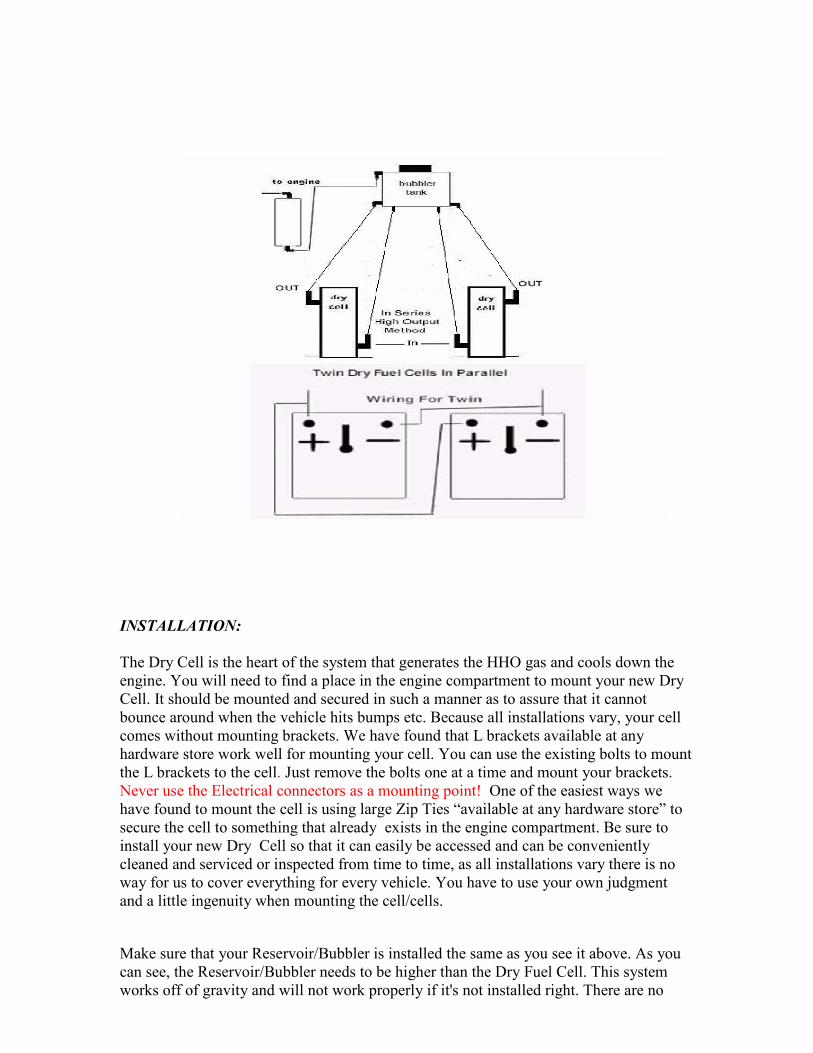
INSTALLATION: The Dry Cell is the heart of the system that generates the HHO gas and cools down the engine. You will need to find a place in the engine compartment to mount your new Dry Cell. It should be mounted and secured in such a manner as to assure that it cannot bounce around when the vehicle hits bumps etc. Because all installations vary, your cell comes without mounting brackets. We have found that L brackets available at any hardware store work well for mounting your cell. You can use the existing bolts to mount the L brackets to the cell. Just remove the bolts one at a time and mount your brackets. Never use the Electrical connectors as a mounting point! One of the easiest ways we have found to mount the cell is using large Zip Ties “available at any hardware store” to secure the cell to something that already exists in the engine compartment. Be sure to install your new Dry Cell so that it can easily be accessed and can be conveniently cleaned and serviced or inspected from time to time, as all installations vary there is no way for us to cover everything for every vehicle. You have to use your own judgment and a little ingenuity when mounting the cell/cells.
Make sure that your Reservoir/Bubbler is installed the same as you see it above. As you can see, the Reservoir/Bubbler needs to be higher than the Dry Fuel Cell. This system works off of gravity and will not work properly if it's not installed right. There are no
pumps involved with the circulation. Another important device “although optional” is the secondary bubbler. Some call this a scrubber. In any case, this keeps any electrolyte from entering into the engine which could cause damage by cylinder washout or trigger the check engine light. It also keeps buildup from occurring in the output line If you install the hydrogen generator without this, you are taking a chance of the engine sucking electrolyte into the intake manifold. This is particularly damaging to diesel engines because it could easily cause engine lockup. While it is rare for any of the above to happen it is possible and we leave it up to you whether or not to use a secondary bubbler. If you're not sure of something, Email us at: [email protected]. IMPORTANT: Try to install your new Dry Cell as far away from the heat of your engine as possible. Locate the coolest available place in the engine area. We cannot give you an exact number here for what is “too hot”, because there is a combination of heating factors here: weather, engine, and the electrolysis process itself. There is a situation called Thermal Runaway, where an increase in temperature changes the conditions (in this case the rise in electrical current) that can cause a further increase in temperature that could lead to a destructive result. By using a PWM (Pulse Width Modulator) to control the amperage delivered to the cell this can be avoided completely. We highly recommend using one.
When making the connection from the cell to the intake of the engine you need to install a Flashback Arrestor between the Bubbler/Reservoir and the intake. This is not optional! It is for your own safety. In the event of an engine backfire the Flashback Arrestor stops any flame from reaching the bubbler and destroying it and/or possibly causing a fire.
The Flashback Arrestor we include in our kits is by far the best on the market. It is designed to open while under engine vacuum and is not designed to be used while the cell is run on the bench. 99 % of backfires occur while the engine is trying to start and during that time our Flashback Arrestor is closed and will not allow any flame from a backfire to reach the bubbler/reservoir. Once the engine has started the Flashback Arrestor opens to allow the HHO to be drawn into the engine by the engines vacuum.
For vehicles with EFI (Electronic Fuel Injection) the HHO line to the engine should be connected at or near the intake manifold.
Now let's move on to connections and supply lines.
Your new Dry Fuel Cell is operated by vacuum pressure from your vehicle’s engine, plus a 12 Volt supply from your vehicle’s electrical system. The cell can be designed to operate on 12 or 24 Volts but as standard all our cells are shipped with a 12 volt configuration and should not be used with 24 volts. If your vehicles system is 24 volts it requires a cell with a special plate configuration. If you have a 24 volt system contact us. Refer to the wiring diagram below. If you are uncomfortable or unsure of your ability to understand the electrical connections and related wiring… DO NOT ATTEMPT IT YOURSELF!!! Seek the assistance of a qualified Mechanic.
Connecting The Power Source Note: The following illustration is a very basic 12 volt power hookup method without a relay, PWM (Pulse Width Modulator) and/or amp meter installed. This is just to give you an idea of how it works. You should never install your Cell this way! For a better 12 volt powering method with the use of a fuse, relay and PWM, see the diagram below this one or the diagram under “KEEPING THE HHO GENERATOR COOLER & MORE EFFICIENT”
The diagram below shows a much better way to wire your cell.
When wiring your system you will find it very helpful to have a wiring diagram for your particular vehicle.
Useful resource: http://www.AHDOL.com - the Automotive Hobbyists Digital Online Library (AHDOL) provides FACTORY WIRING DIAGRAMS upon request, for vehicles sold in North America between 1984 and 2010. Cost of complete vehicle diagrams per vehicle is $11.99 and is guaranteed to be delivered, via email, within 24 hours. 1. Identify a point in your vehicle’s electrical system which has 12 Volts (positive) present ONLY WHEN THE IGNITION SWITCH IS IN THE ON POSOTION, such as the starter solenoid or a similar circuit. Make sure your connection point is off when the Ignition Switch is in the off or accessory position. It is also wise to install a separate Amp Meter inside your car so you can monitor your cell at all times. 2. Turn the switch off and take out the key. Connect the positive 12 Volts (point identified above) to the red terminal of the device, using the red wire supplied. 3. Connect the black terminal of the device to a good ground source near the Dry Cell using the black wire provided. This can be done by connecting to the negative battery terminal or by a bolt or screw connected to the frame or body of your vehicle (See
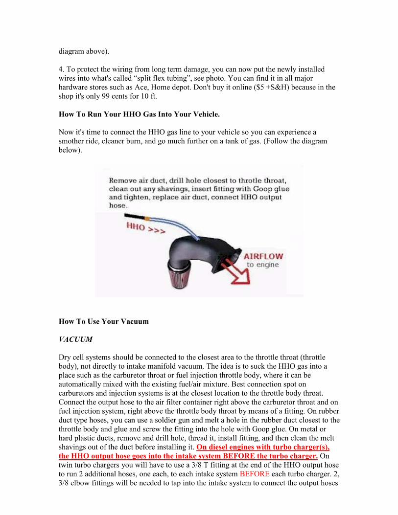
diagram above). 4. To protect the wiring from long term damage, you can now put the newly installed wires into what's called “split flex tubing”, see photo. You can find it in all major hardware stores such as Ace, Home depot. Don't buy it online ($5 +S&H) because in the shop it's only 99 cents for 10 ft. How To Run Your HHO Gas Into Your Vehicle. Now it's time to connect the HHO gas line to your vehicle so you can experience a smother ride, cleaner burn, and go much further on a tank of gas. (Follow the diagram below).
How To Use Your Vacuum VACUUM Dry cell systems should be connected to the closest area to the throttle throat (throttle body), not directly to intake manifold vacuum. The idea is to suck the HHO gas into a place such as the carburetor throat or fuel injection throttle body, where it can be automatically mixed with the existing fuel/air mixture. Best connection spot on carburetors and injection systems is at the closest location to the throttle body throat. Connect the output hose to the air filter container right above the carburetor throat and on fuel injection system, right above the throttle body throat by means of a fitting. On rubber duct type hoses, you can use a soldier gun and melt a hole in the rubber duct closest to the throttle body and glue and screw the fitting into the hole with Goop glue. On metal or hard plastic ducts, remove and drill hole, thread it, install fitting, and then clean the melt shavings out of the duct before installing it. On diesel engines with turbo charger(s), the HHO output hose goes into the intake system BEFORE the turbo charger. On twin turbo chargers you will have to use a 3/8 T fitting at the end of the HHO output hose to run 2 additional hoses, one each, to each intake system BEFORE each turbo charger. 2, 3/8 elbow fittings will be needed to tap into the intake system to connect the output hoses
to. WARNING: If you put the HHO output hose into the intake AFTER the turbo charger(s), the HHO system will become pressurized, damaging the HHO system. (See typical HHO output hose connection diagram above) FINAL SETUP Filling the Reservoir/Bubbler with DISTILLED WATER & THE ELECTROLYTE: ELECTROLYTE
Use only KOH (Potassium Hydroxide) as your electrolyte. If you don’t already have some KOH, it is available at: http://aaa-chemicals.com Using 1 gallon of Distilled water, add 2 tablespoons of KOH (Potassium Hydroxide) to the water and mix well. This is just a starting point for the mixture. If you ordered one of our kits that included a PWM you can start with 4 tablespoons of KOH to 1 gallon of distilled water, “It is very important to use only distilled water, any other kind of water will contain minerals that will react to the electrolysis process and possibly damage the cells plates”. If you do not have a PWM we highly advise you to get one. Without a PWM it is necessary to use the electrolyte (KOH) mixture to control the amperage and that is not a simple chore. Without a PWM you have to either increase or decrease the strength of the mixture until you get the amperage you want when the cell has fully warmed up and regardless of how you mix it the amperage will probably not remain constant. Make your life easy and get a good PWM.
USE CAUTION!
Potassium Hydroxide can burn the skin, eyes, etc. Wear protective clothing, gloves, safety glasses, etc, while handling and mixing the KOH. Read the precautions on the label. In reality Potassium Hydroxide is no different than most other caustic chemicals. Drain cleaners, etc. Just read the caution labels and use common sense… “Like don’t drink it or get it on you”. Try to use at least a 2 quart Bubbler /Reservoir (Larger if space permits).
Once you have your mixture ready, pour it into the top of the Bubbler /Reservoir up to the water level line. (see sample diagram below) This is just a sample of a 2 quart Reservoir/Bubbler. Be sure to leave about 1/3 of the tank empty. While you are filling the unit, you should be able to see water running down to your Dry Fuel Cell. If you don't see any water going down the tube, this could mean you don't have the Reservoir/Bubbler high enough above your Dry Cell. Always try to install your Dry Cell at the lowest level on your vehicle.
TEST RUN: 1. Start by checking all your connections. Make sure your amp meter and inline fuse have been installed. 2. Now start your vehicle. While it's running, watch for bubbling action inside of your Reservoir/Bubbler. You should be able to see the gas entering the Reservoir/Bubbler. 3. If you have done everything right, within a short time, you will notice that the engine starts to sound dramatically different. It will sound smoother and quieter. Your RPM's may be unstable for a couple of minutes. This is normal. The HHO is starting to change the combustion cycle and cancels the pinging and the engine is now adjusting to the changes. Your RPM's will normalize in a couple of minutes. Congratulations! Your new Dry Fuel Cell is now producing Hydrogen Gas! The below section refers to dealing with your vehicles computer. If your vehicle is a 1996 or newer you should use the FS2 Module to handle all the computer related issues and you can disregard the below section. The FS2 Module is vehicle specific, “we program it
for your particular vehicle”. If you ordered a kit that did not include the FS2 Module and you need one, contact us at: [email protected]
Too many people are under the impression that giving an engine a lot of HHO equates to better mileage and that is not true. There is a point where more HHO will actually reduce mileage instead of increasing it. The real key to getting better mileage is keeping the amperage to the cell at a reasonable level and making sure the cars computer (ECU) is not overriding the benefits the HHO is trying to accomplish. If your vehicle is a 1996 or newer the fuel delivery system is controlled by a very sophisticated computer system. That system will sense the additional oxygen in the HHO and as a result the computer will think the engine is running lean and instructs the injectors to give the engine more gas or diesel fuel. This will completely defeat any gains the Hydrogen assist system would otherwise give you. If your vehicle is a 1996 or newer use the FS2 Module above to give the ECU the proper instructions to follow. Dealing with your vehicles computer (ECU) on 1995 and older Vehicles You may have heard that it is necessary to fool your computer. That statement is incorrect and the people using it are in error. In reality, you need to bring your vehicles computer back to sanity. Your vehicles computer doesn’t have the slightest idea of what Hydrogen is. While it does get information about Oxygen from various sensors it doesn’t now about the Hydrogen in HHO when it is introduced to your engine. The only thing the computer recognizes is the additional Oxygen. It doesn’t realize the additional Oxygen is there for a reason. This all goes back to the Auto Industry and their total disregard for engine efficiency. By installing your Hydrogen assist system you are creating a much more efficient engine. But, the vehicles computer doesn’t know that. It
thinks something is wrong. It learns about the extra Oxygen from it sensors and thinks the engine is running lean when in reality it is not. So, the computer mistakenly corrects for the additional Oxygen by dumping more gas into your engine and erasing any mileage gains. In order to bring your vehicles computer back to sanity, we have to change the information it receives about Oxygen from its sensors. Most modern-day fuel injected vehicles use a computer and oxygen-sensing devices to monitor and maintain “what they think” is the correct air/fuel ratio. One of the key sensing devices is the oxygen sensor also called an exhaust or (02) sensor. Fuel injected vehicles have one or more oxygen sensors installed on them. The computer determines what the air/fuel ratio is, based on the amount of oxygen in the exhaust, as reported by the oxygen sensor. When a fuel saving device is installed, such as an HHO generator, the petroleum fuel is burned more completely. One of the results of this is that there is more oxygen (and less unburned hydrocarbons) in the exhaust stream. This is a good thing, and is in fact, what we are trying to achieve. However, the computer will perceive this condition as a “too lean” air/fuel mixture. In other words, what is now a desirable condition in the exhaust will be interpreted as “not enough fuel”, and the computer will direct the fuel injectors to increase the amount of fuel being pumped into the engine. The result is that the oxygen sensor and computer prevents efficient combustion from occurring! It will therefore cancel out most of the improvements we have just made. The Solution The oxygen sensor “tells” the computer what the oxygen content is by providing a voltage on its signal wire between 0 and 1 volt. 450 millivolts (.45 volts) means that the fuel/air mixture is correct. Higher values means the mix is rich (has too much gas), and lower voltages means the mix is lean. By adding voltage to the sensor’s output, we can compensate for the additional oxygen in the exhaust and lean out the vehicle to get maximum MPG. You must use a device that will enhance the signal to the computer (ECU), such as an EFIE (electronic fuel injection enhancer) which goes on the oxygen sensor(s) BEFORE the catalytic converter(s). EFIE INSTRUCTIONS
DIAGRAM OF TYPICAL 02 SENSOR LOCATION
Most cars have oxygen sensors both before and after the catalytic converter. The ones downstream from the converter do not need to be treated. Their data is used to determine when the converter has gone bad, but are not used in the air/fuel ratio calculations. These devices are only needed for all upstream oxygen sensors.
DIAGRAM OF A TYPICAL EFIE DEVICE (02 Enhancer)
You must use caution when purchasing an EFIE (02 Enhancer) many people selling MAP/MAF Enhancers also use EFIE in their advertising. A MAP/MAF Enhancer is not an EFIE 02 Enhancer. They are completely different products. We Carry both MAP/MAF Enhancers and EFIE 02 Enhancers. You can contact us at: [email protected] to purchase them. If you want the best results, besides addressing the O2 sensors, you need to address other computer components as well. If the vehicle has either a MAP (manifold absolute pressure) sensor or a MAF (mass airflow sensor),, you need to install a MAP/MAF enhancer on it (see illustration below). In some cases the vehicle may have both, in which case you only address the MAP sensor.
Most all fuel injected engine have a coolant temperature sensor CTS (see illustration & instructions below) and some have a separate intake air temperature IAT sensor (see instructions below). These sensors can be leaned out by upping the temperature that the computer sees (not your dash gauge) by installing a resistor in parallel to the sensor wires. Our testing has found that installing a single pull single throw on/off switch eliminates cold start problems that the installation of the resistor produces. Make no mistake about it, if all possible computer components are not addressed properly for leaning out the computer will eventually override single fixes and undo them after several weeks of driving, rendering the fuel mileage increase to null. Detailed instructions come with all purchased computer enhancers (and OUR enhancers come with detailed instructions that can be downloaded from this page) and these adjustments involve trial and error fine tuning until you get it just right or the check engine light might come on.
INTAKE AIR TEMPERATURE SENSOR IAT The IAT is less sensitive to cold start issues. You can add more temp to this signal than you can to the CTS. Just keep in mind that you are not only lowering your lean-out limits,
you are also retarding your ignition timing. If you put a timing light on the engine as you adjust IAT values, you won't see the timing change. The timing changes under load. Hotter air is more prone to detonation. This is why the ECU retards the timing. If you are tuning on the hottest day of the year, you may find out just how high of a signal you can generate before setting codes. Typically it is in the 240° F range. If you are tuning in the middle of February, then you can offset the signal from your base cold reading and things will be fine for now. Come June or August, this setting may be high enough to trip codes. Allow for this when tuning. KEEPING THE HHO GENERATOR COOLER & MORE EFFICIENT
While the hydrogen generator will produce sufficient hydrogen output, pending the correct electrolyte mix, and run within heat tolerances, adding a PWM (pulse width modulator) will definitely improve the temperature control and HHO production more efficiently. Why? Because you can control the amperage draw below the limit it is capable of drawing. For example, if the unit is designed to run between 12-18 amps and the unit draws more than that, adding a PWM you can tune it down and can keep the amp draw within the specs, keeping a thermo runaway in check. It also changes the voltage wavelength, which is conducive to better HHO production. NO WARRANTY is expressed or implied concerning the use of these devices for any particular application. Use of these devices is at your own risk. These devices are not intended for use in violation of State or Federal law or regulations. Compliance with any State or Federal laws or regulations is the responsibility of the buyer.
BUT WON'T IT VOID MY CAR WARRANTY? We get this question all the time. The answer is simple: Your car or truck is being damaged right now by UNBURNED FUEL! Our technology will not only help eliminate carbon deposits caused by unburned gasoline - but will ACTIVELY clean out your engine every time you drive. Over the first few weeks you will notice that the engine becomes smoother and smoother. Then it will level off at a new level - at which the engine continues to clean itself. Your new HHO Dry Cell makes the engine quiet, and calm. The engine stops knocking or "pinging". The HHO changes the combustion cycle into a more even or "round" cycle. This happens IMMEDIATELY upon installation, and from that moment on, your engine works in a new way. The effect is not only less noise, it also has less vibration, resulting in reduced strain on the transmission (thus smoother gear shifts), cleaner pistons and valves, and generally better engine operation. Water vapors cools down the engine. For years, heavy trucks have been using water injection systems that cost up to $15,000 to cool their engines. Truck owners are very sensitive to maintenance expenses and they know from years of experience that water reduces their breakdowns and overall operating costs. Our Dry Fuel Cell system will widen the torque range and make vehicles accelerate faster. After acceleration, you don't have to press the gas pedal as much to keep going. Trucks pull better uphill with HHO Gas. Would you say that less strain on that Detroit diesel engine must result in less wear and tear over the life of the engine? EASY UNDO: Our technology does not change your vehicle's engine or computer, so if you ever decide that you don't want this system, you can unhook it in less than a minute and your engine is just as it was - only cleaner! We hope these instructions have helped you and we invite you to test this technology for yourself just like we've done, and just like 1000's of vehicle owners and fleet managers from around the world have done. Now go show others how to save money on their fuel bills. Thanks again for purchasing the best Dry Cell on the Market. If you have any questions please contact us at: [email protected]