112/252, 14, 18 SERIES HI-FLO CENTRIFUGAL PUMPS High flow water transfer. Suitable for tank filling & irrigation. OWNER`S MANUAL Should the installer or owner be unfamiliar with the correct installation or operation of this type of equipment, contact the distributor or manufacturer for correct advice before proceeding with installation or operation of the product ® ONGA
Transcript
1
112/252, 14, 18 SERIESHI-FLO CENTRIFUGAL PUMPS
High flow water transfer. Suitable for tank filling& irrigation.
OWNER`S M
ANUAL Should
the
installer
or
owner
be
unfamiliar
with
thecorrect installation or operation of this type ofequipment, contact the distributor or manufacturerfor correct advice before proceeding with installationor operation
of
the
product
®ONGA
2
RELAX - YOU’ VE BOUGHT AN ONGA...
1. Continual Product ImprovementWe employ the best engineers both in Australia andaround the world to develop new and better ways totake water further.
2. Operational ExcellenceThere is only one standard that we set ourselves for bothproduct quality and the quality of our service. Thatstandard is excellence... to have no-one better than usat what we do... nothing short of that is acceptable.
3. A Fair PriceOnga products are neither the cheapest nor the mostexpensive in their field. Our products do, on the otherhand, always represent very good value for money - theyalways have and they always will.
4. Our Team of DealersThe hand picked authorised Onga dealer networkthroughout Australia and worldwide are second to none.We invest considerable time and resources training andsupporting them through the Onga Training Academy.
Congratulations on your decision to purchase an Onga product. Onga is one of the best known brands in its field, with a proud local and International reputation.
Onga is a brand for reliability, value for money and technological innovation.So why does Onga lead its field? Here`s a few simple reasons:
You`ll find an Onga product wherever people need to move water in 3 broad markets covering:
Technologically advanced solutions for moving and treating water in the Home, Garden and Pool.
This is the safety alert symbol. When you see thissymbol on your pump or in this manual, look for one of thefollowing signal words and be alert to the potential forpersonal injury:
DANGER warns about hazards that will cause seriouspersonal injury, death or major property damage if ignored.
WARNING warns about hazards that can cause seriouspersonal injury, death or major property damage if ignored.
CAUTION warns about hazards that will or can causeminor personal injury or property damage if ignored.
The label NOTICE indicates special instructions which areimportant but not related to hazards.
Carefully read and follow all safety instructions inthis manual.
Electrical SafetyWire motor for correctvoltage. See‘Electrical’ section ofthis manual andmotor label.
Ground motor beforeconnecting to powersupply.
Meet National or localelectrical code for allwiring.
Do not touch an operating motor. Modern motorsare designed to operate at high temperatures. Toavoid burns when servicing pump, allow it to coolfor at least 20 minutes after shut-down beforehandling.
General Safety
To avoid heat build-up, over pressure hazard andpossible injury, do not use in a pressure tank(domestic water) system. Do not use as a boosterpump; pressurised suction may cause pump body toexplode.
Do not allow pump or piping system to freeze.Freezing can damage pump and pipe, may lead toinjury from equipment failure and will void warranty.
Pump water only with this pump.
Periodically inspect pump and system components.Wear safety glasses at all times when working onpumps.
5
a) Preparation for operationRead these instructions firstInspect your pump for shipping damage. Report any damage to your Ongadealer. Make sure the suction piping is free of air leaks and is laid so that it rises evenly from water source to pump. This makes priming easier and avoids airlock.b) Pump ProtectionWarranty of these pumps is void unless they are housed correctly and protectedfrom weather, floods, chemicals, dust, vermin, insects etc. Housing used should be weather proof and well vented so that motor heat can escape. To obtain best performanceopumps should be installed as close to water as possible. Depending on application they do not have to be bolted down.c) Pump MountingThe pump must be mounted on a solid, level, vibration free surface.Moulded pumps can be damaged by connected piping. Pipe should be supported so the pump casing is not strained by the pipe weight or misalignment.
This appliance is not intended for use by young children or infirm personswithout supervision. Children should be supervised at all times when near thisappliance.
INSTALLATION
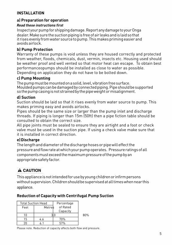
Total Suction Head Feet Metres
Percentage of Rated Capacity
10 3.0 80% 15 4.6 70% 20 6.1 57%
Reduction of Capacity with Centrifugal Pump Suction
Please note. Reduction of capacity affects both flow and pressure.
d) SuctionSuction should be laid so that it rises evenly from water source to pump. Thismakes priming easy and avoids airlocks.Pipes should be the same size or larger than the pump inlet and discharge threads. If piping is longer than 15m (50ft) then a pipe fiction table should beconsulted to obtain the correct size. All pipe joints must be sealed to ensure they are airtight and a foot or check valve must be used in the suction pipe. If using a check valve make sure thatit is installed in correct direction. e) DischargeThe length and diameter of the discharge hoses or pipe will effect thepressure and flow rate at which your pump operates. Pressure ratings of allcomponents must exceed the maximum pressure of the pump by anappropriate safety factor.
6
ELECTRICALDisconnect power to motor before working onpump or motor.
Ground motor before connecting to electrical powersupply. Failure to ground motor can cause severeor fatal electrical shock hazard.
Do not ground to a gas supply line.
To avoid dangerous or fatal electrical shock, turnOFF power to motor before working on electricalconnections.
Supply voltage must be no lower than 6% or no higher than 10% of motor label voltage. Incorrect voltage can cause fire or damage motor and voids warranty. If in doubt consult a licensed electrician.
If possible, connect pump to a separate branchcircuit with no other appliances on it.
An earth leakage or residual current protectiondevice must be fitted to all installations, ratedresidual operating current not exceeding 30mA.
A voltage surge protector should be fitted asvoltage spikes or incorrect voltage can cause fireor seriously damage the motor.
Install, ground and maintain this pump in accordance with electrical code require-ments. Consult your local building inspector for information about codes.
Provide a correctly fused Residual Current Device or Earth Leakage Device forprotection while working on motor. Consult local or national electrical codes forswitch requirements.
Disconnect power before servicing motor or pump. If the RCD or Earth Leakagedevice is out of sight of the pump, lock it open and tag it to prevent unexpectedpower application.
7
ELECTRICAL (continued)
If service is required to the pecialised power lead assembly. Warranty is void if unauthorised modifications are made to any component.
power lead, it must be replaced with the appropriate s
Protect current carrying and grounding conductors from cuts, grease, heat, oil,and chemicals.
Motor has automatic internal thermal overload protection. If motor has stoppedfor unknown reasons, thermal overload may restart motor unexpectedly, which could cause injury or property damage. Disconnect power before servicing motor.
If any of the preceding is confusing, consult a licensed electrician.
Make ground connection to green grounding terminal under capacitor cover lidmarked and/or E.
230 volt single phase motors are supplied as standard with on winding thermal overload protection and are designed to plug directly into a 10 amp (GPO) domestic power supply to local electrical authority specifications.
OPERATION
Priming the Pump (Suction lift installations)
NOTICE: ‘Priming’ refers to the pump expelling all air in the system andbeginning to move water from its source out into the system. It does notrefer only to pouring water into the pump (although pouring water in is usuallythe first step).
NOTICE: NEVER run pump dry. Running pump without water in it willdamage seals and can melt impeller, diffuser and seal plate. To prevent damage,fill pump with water before starting.
1. Remove priming plug (located on top of the pump casing).2. Make sure discharge valve(s) and any hoses on discharge side of the
pump are open.3. Fill pump and suction pipe with water.
8
OPERATION (continued)
4. Replace priming plug, using Teflon tape on thread; tighten plug.NOTICE: If a priming tee and plug have been provided for a longhorizontal run, be sure to fill suction pipe through this tee and replaceplug. (Don’t forget to Teflon tape the plug.)
5. Start pump: water should be produced in 10 minutes or less, the timedepending on depth to water (suction lift not more than 6 metres) andlength of horizontal run.
If no water is produced within 10 minutes, stop pump, release all pressure,remove priming plug, refill and try again.
Hazardous pressure and risk of explosion and scalding. If pump isrun continuously at no flow (that is, with discharge shut off or with-out priming), water may boil in pump and piping system. Under steampressure, pipes may rupture, blow off fittings or blow out of pumpports and scald anyone near.
To prevent explosion, do the following:
A. Ensure discharge (valve, hose nozzle, etc.) is open whenever pump isrunning.
B. If pump fails to produce water when attempting to prime, release allpressure, drain pump and refill with cold water after every twoattempts.
C. When priming, monitor pump and piping temperature. If pump or pipingbegin to feel warm to the touch, shut off pump and allow system tocool. Release all pressure in system and refill pump and piping with coldwater.
9
SERVICE & MAINTENANCE
This centrifugal pump requires little or no regular serviceother than reasonable care and periodic cleaning. Occasion-ally, however, a shaft seal may become damaged and must bereplaced. The procedure as outlined below will enable you toreplace the seal.
NOTICE: The highly polished and lapped faces of the seal areeasily damaged. Read instructions and handle the seal withcare.
REMOVAL OF OLD SEAL1. After unscrewing impeller, carefully remove rotating part of seal by
prying up on sealing washer, using two screwdrivers (see Figure A).Use care not to scratch motor shaft.
2. Remove seal plate (baffle) from motor and place on flat surface, facedown. Use a screwdriver to push ceramic seat out from seal cavity (seeFigure B).
INSTALLATION OF FLOATING SEAL(Figure C)1. Clean polished surface of floating (ceramic) seat with clean cloth.2. Turn seal plate over so seal cavity is up; clean cavity thoroughly.3. Lubricate outside rubber surface of ceramic seat with silicone based
lubricant, ensuring no lubricant gets on the polished ceramic wear face,and press firmly into seal cavity with finger pressure. If seat will notlocate properly in this manner, place a cardboard washer over polishedface of seal and press into seal cavity using a socket or 13mm piece of standard pipe.
½” 13mm
Liquid may be HOT, release pressure before servicing.
½” 13mm socketor 13mm pipe
10
Liquid may be HOT, release pressure before servicing.
Pump should only be serviced by qualified personnel. Make sure toprime pump before operating. NEVER run pump dry!
If the supply cord is damaged, it must be replaced by themanufacturer or an authorised service agent.
SERVICE & MAINTENANCE (continued)
4. Dispose of cardboard washer. If need ensure polished surface of seal seat is free of dirt and has not been damaged during insertion. Remove any excess lubricant that may have been dislodged during insertion andensure that there is no lubricant on the polished face of the seal.
INSTALLATION OF ROTATING PART OF SEAL UNIT(Figure D)
2. Reinstall seal plate using extreme caution not to hit ceramic portion ofseal on motor shaft.
3. Inspect shaft to ensure that it is clean.
1. Clean face of sealing washer with clean cloth.
4. Lubricate outer face of rubber drive ring with silicone-based lubricant,ensuring no lubricant touches the polished face, and slide assembly onmotor shaft (sealing/polished face first) until rubber drive ring hits shaftshoulder (ensure that the polished face does not hit the motor shaft).
5. Screw impeller on shaft until impeller hub hits shaft shoulder. This willautomatically locate seal in place and move the sealing washer face upagainst the facing seat.
Should you have any difficulty replacing the seal unit please contact your localpump professional.
11
Troubleshooting Guide
Symptom Cause Remedy Pump must be primed; make sure that the pump casing is full of water. Refer priming instructions. Make sure there are no leaks in suction piping. Make sure suction pipe inlet is well below the water level to prevent pump from sucking air.
Suction leaks / lost prime
Suction lift of 3 to 6 metres will reduce performance. Suction lift of more than 6 metres will prevent pumping and cause pump to lose prime. In either instance, move the pump closer (vertically) to water source. Ensure the suction pipe diameter is large enough. Make sure that the impeller is not clogged. This should be checked by qualified personnel only. Impeller and diffuser may be worn. If so, check with your local Onga dealer or suitably qualified personnel.
Clogged pipe / impeller, worn impeller.
Pump may be trying to push too high a column of water. If so, a “higher head” pump is required.
No power at outlet. Use another electrical appliance that is known to work to check the power outlet.
Blown fuse. Check fuse and replace if necessary.
Incorrectly sized pipe. Check pipe work pressure losses and replace with larger diameter pipe if required.
Motor burnt out due to voltage spike or flooded by water.
The motor may need replacing.
Valves turned to the closed position.
Check the plumbing to ensure the valves are in the correct position for pumping on the suction and discharge.
Pump failure or reduced capacity or reduced discharge pressure.
Air ingress to system. Prime the pump. Check that there are no air leaks in the suction piping or fittings. Check that there are no leaks coming from beneath the pump.
Thermal Overload tripping:The thermal overload is automatic and resets after the pump has cooled. If thermal continues to trip there is something wrong with the pump.
12
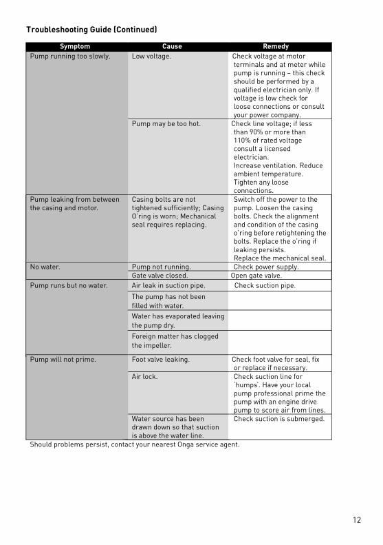
Troubleshooting Guide (Continued)
Symptom Cause Remedy
Low voltage. Check voltage at motor terminals and at meter while pump is running – this check should be performed by a qualified electrician only. If voltage is low check for loose connections or consult your power company.
Pump running too slowly.
Pump may be too hot. Check line voltage; if less than 90% or more than 110% of rated voltage consult a licensed electrician. Increase ventilation. Reduce ambient temperature. Tighten any loose connections.
Pump leaking from between the casing and motor.
Casing bolts are not tightened sufficiently; Casing O’ring is worn; Mechanical seal requires replacing.
Switch off the power to the pump. Loosen the casing bolts. Check the alignment and condition of the casing o’ring before retightening the bolts. Replace the o’ring if leaking persists. Replace the mechanical seal.
Pump not running. Check power supply. No water. Gate valve closed. Open gate valve.
Foot valve leaking. Check foot valve for seal, fix or replace if necessary.
Air lock. Check suction line for ‘humps’. Have your local pump professional prime the pump with an engine drive pump to score air from lines.
Pump will not prime.
Water source has been drawn down so that suction is above the water line.
Check suction is submerged.
Should problems persist, contact your nearest Onga service agent.
Pump runs but no water. Air leak in suction pipe. Check suction pipe.The pump has not beenfilled with water.Water has evaporated leavingthe pump dry.Foreign matter has clogged the impeller.
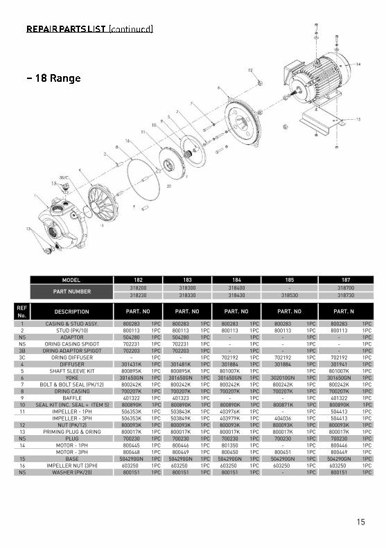
13
REPAIR PARTS LISTDrawings are indicative only, product appearance may change slightly.