Includes: System Design Unit Selection System Layout Unit Specifications Module DES - Hi-Velocity System Design 051717 Hi-Velocity System Design HE-Z/HE-B Series Manufactured By Small Duct High Velocity Heating, Cooling and Home Comfort Systems • Quiet Operation • Constant Air Circulation • Multi-Positional Fan Coil • Easy Installation & Maintenance • Space Saving Small Diameter Ducts • Zoning Capable right out of the Box! • Many Attractive Vent Plate Options • Superior Heating, Cooling and IAQ • Eliminate Hot and Cold Spots Features:
Transcript
Includes:System DesignUnit SelectionSystem Layout
Unit Specifications
Module DES - Hi-Velocity System Design 051717
Hi-Velocity System DesignHE-Z/HE-B Series
Manufactured By
Small Duct High Velocity Heating, Cooling and Home Comfort Systems
It is in rooms such as this that a hybrid system of both radiant heating and the Hi-Velocity System would be the optimum system to provide comfort conditioning. This will provide the home owner with good indoor air quality, and warm floor comfort (not as effective if carpet is laid down).
A common approach to a hybrid system is to heat the basement with radiant tubing. The main floor and 2nd floor if applicable would be heated with the Hi-Velocity System. A few outlets can also be placed in the basement to provide air circulation, and supplementary heating if required.
When running Hi-Velocity Systems from a low water temperature system (e.g. A hot water tank), care must be taken when designing and installing the system. Due to the lower water temperature there will be less BTUH’s and therefore a lower supply air temperature, it is imperative that the water temperature is known at the design stage. If possible the highest temperature setting should be used, and a water tempering valve installed for the domestic use.
To size a Hi-Velocity System for a residence/commercial space, it is necessary to have an accurate heat loss/gain done for the structure. This will ensure the proper equipment is used for cooling and heating.
A heat loss/gain is done for each room, which will give a total BTUH load for the structure.
Table DES-01 - Example Data for Fig. DES-02Room Name BTUH Loss BTUH GainNookKitchenBathBed #1Bed #2Dining Rm.FoyerFamily Rm.Master BedM.Bath/WIC
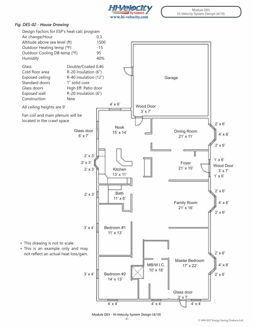
The design factors used to achieve this heat loss/gain are shown on Fig. DES-02.
Hi-Velocity System Design
One of the benefits of using a hydronic system is the versatility that you have when designing the heating system. Radiant floor heating is an excellent system, but it does have limitations. You cannot have cooling, air filtration, and humidification with a straight radiant heating system. Similarly, sometimes a forced air system is not the only option available for a house, especially if it has a lot of ceramic tile or concrete floor areas.
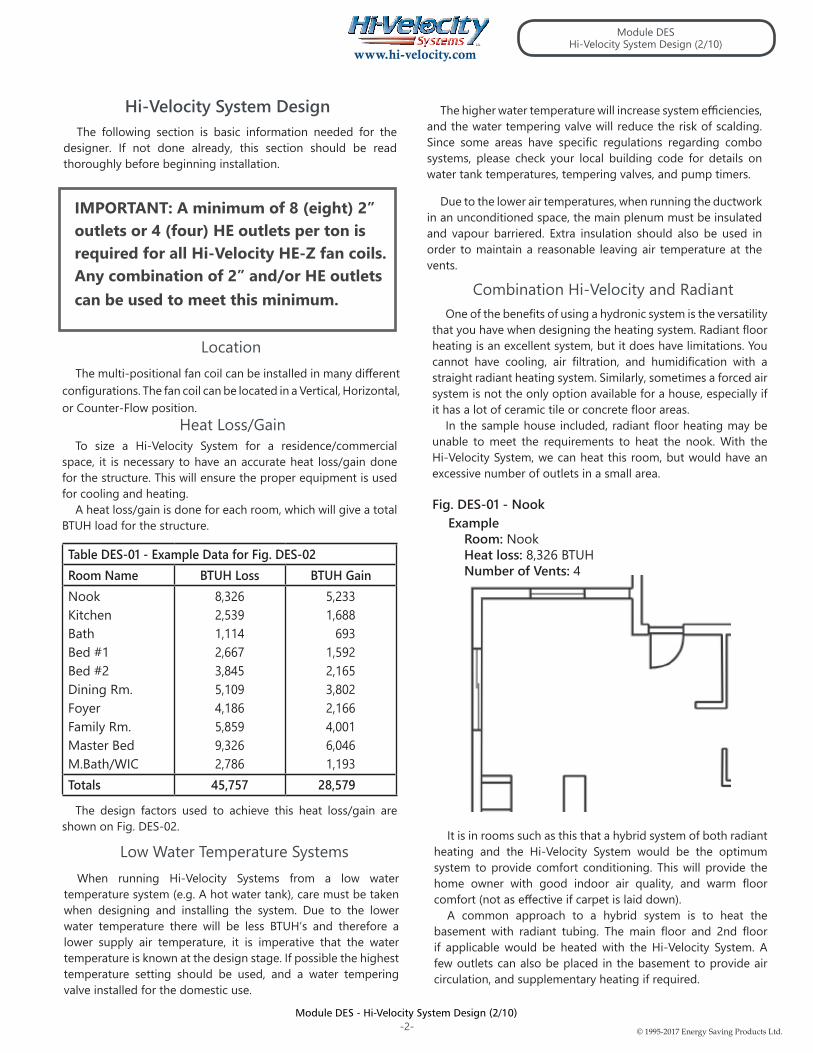
In the sample house included, radiant floor heating may be unable to meet the requirements to heat the nook. With the Hi-Velocity System, we can heat this room, but would have an excessive number of outlets in a small area.
Fig. DES-01 - NookExample
Room: NookHeat loss: 8,326 BTUHNumber of Vents: 4
Combination Hi-Velocity and Radiant
Low Water Temperature Systems
Heat Loss/Gain
The following section is basic information needed for the designer. If not done already, this section should be read thoroughly before beginning installation.
Module DESHi-Velocity System Design (2/10)
Due to the lower air temperatures, when running the ductwork in an unconditioned space, the main plenum must be insulated and vapour barriered. Extra insulation should also be used in order to maintain a reasonable leaving air temperature at the vents.
The higher water temperature will increase system efficiencies, and the water tempering valve will reduce the risk of scalding. Since some areas have specific regulations regarding combo systems, please check your local building code for details on water tank temperatures, tempering valves, and pump timers.
LocationThe multi-positional fan coil can be installed in many different
configurations. The fan coil can be located in a Vertical, Horizontal, or Counter-Flow position.
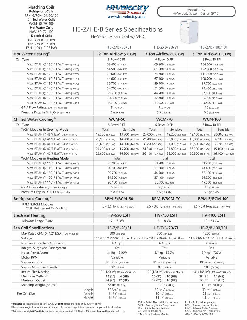
IMPORTANT: A minimum of 8 (eight) 2” outlets or 4 (four) HE outlets per ton is required for all Hi-Velocity HE-Z fan coils. Any combination of 2” and/or HE outlets can be used to meet this minimum.
With the total load known for the structure, it is now possible to select the proper Hi-Velocity unit (Specifications - Pg. 9).
Table DES-02 – Selected fan coilSelected fan coil:Entering Water TempHouse Heat Loss:House Heat Gain:Minimum Outlets:Maximum OutletsSelected Condenser
HE-Z-70 H180°F45,757 BTUH28,579 BTUH2” = 20 HE = 102” = 32 HE = 162.5 ton
Once the unit has been selected, the average numbers of outlets can be determined (Specifications - Pg. 9). To determine the average number of vents, the minimum is added to the maximum and divided by two.
Example: (Using only 2” outlets)(Min Outlets (20) + Max Outlets (32) / 2 = 26) * *Example shown using only 2” outletsWith the average number of vents known it is now possible
to determine the average BTUH output per vent. Dividing the average number of outlets into the fan coil output (Specifications - Pg. 9) will give an average BTUH output per vent.
Example:BTUH per Outlet for HEATING
81,800 BTUH / 26 = 3,146 BTUH/OUTLET(3,146 BTUH delivery per outlet for Heating)
BTUH per Outlet for COOLING30,000 BTUH / 26 = 1,154 BTUH/OUTLET(1,154 BTUH delivery per outlet for Cooling)
The BTUH per outlet is then used to figure out how many outlets are required for each room. As an example, here is a room by room load calculation for the house plan included (Fig. DES-02).
A room (Nook) that has a heat loss of 8,326 BTUH and a heat gain of 5,233 BTUH will need 4 vents.
Example:4 x 3,146 BTUH = 12,584 BTUH(12,584 > 8,326 Heating requirements satisfied)4 x 1,154 BTUH = 4,616 BTUH(4,616 < 5,233 Cooling requirements not satisfied)The heating checks out but the cooling doesn’t in this
example. We allow a 10% variance on vent checks, which gives a little leeway with vent placement. Also with the kitchen being an adjoining room with an extra 620 BTUH it will help the nook maintain the desired temperature
Not all rooms will check out for cooling as illustrated in Table DES-04, we allow a 10% variance on vent checks per room. The Main concern is the total unit output being higher than house BTUH loss. With the venturi action of the Hi-Velocity System the individual rooms will affect each other and help maintain the desired room temperature.
Unit Selection
Average BTUH Per Outlet
Difference in no. of Vents Req’d for Htg & ClgThere may be cases when the number of outlets needed for
heating is significantly different than the amount needed for cooling. This is usually caused by a large appliance load or an excessive amount of windows. If this happens you will have to use the greater number of outlets to provide both heating and cooling for the room. The vents have dampers and can be adjusted for individual room comfort. In cooling mode the outlets must be in the fully open position or there will be a loss in performance and the efficiency of the system.
With the total vents known, the layout of the Hi-Velocity System can now be done. Start with individual vent placements (if you have not already read the section on Vents in System Design, please do so before starting). Then place the main plenum so the flex runs will be the shortest length possible. With the plenum placed, the flex runs can be drawn connecting the vent outlet to the main plenum.
Fig. DES-03 - Placing Vents: Nook
4 Vents distributedevenly throughout
the space.
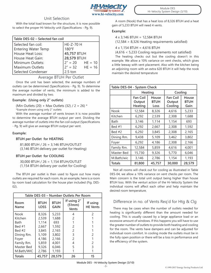
With this room 3 two inch vents would have satisfied the heating requirements, but would not satisfy the cooling requirements. For the nook we need 4 two inch vents for cooling, so 4 two inch vents must be placed in the nook. The vents do have an adjustable damper and can be adjusted for individual room comfort if too much heating is being supplied. In cooling mode the outlets must be in the fully open position.
With a 56/44 split we will be able to reach all vents using standard 10’ and 15’ flex runs. If you have to extend the flex runs longer than 10’, reference Table DES-05 for adjustment factors.
For this layout we have chosen to use a Main Plenum with a 56/44 bullhead tee split. On one side 14 vents will used, while 11 will be used on the other. This is allowable as we can use a Bull Head Tee up to a 60/40 split. If the split is greater than 60/40, a Branch Tee should be used instead of the Bullhead Tee. See Module DUC - Installing Plenum and Branch Duct for Installation Instructions.
The main plenum we choose to use is 8”, it is not required to use 8” for the whole run. If space or cost is a concern, the main plenum can be reduced down to a smaller size. If reducing the plenum, reference Table DES-06 for allowable length and maximum number of vents for the size chosen. Never reduce at a bullhead tee, always reduce after the bullhead tee or you can lose approximately 20% of your airflow.
Once the vents and plenum have been drawn in, the two may now be connected with the flexible branch duct. The minimum flex run is 10’ (3.05m) and the maximum is 25’ (7.62m)
System Layout
Drawing Vent Placement
Drawing the Plenum
Drawing the Flex Runs
To demonstrate a vent layout, we’ll place 4 two inch vents to properly condition the Nook (Fig. DES-03). From Table DES-03 we calculated that the Nook has a Heat loss/gain of 8,326/5,233, which will require 4 two inch vents to satisfy heating and cooling requirements.
The outlets should be located where it is considered to be a “low traffic area”. Typical areas are in the corner of a room, or to the side of a window or door. When the vents are properly located, the home owner can expect to have a nearly draft free home.
Once all the vents have been placed in each room, the main plenum can now be drawn. Figs. DES-04 and DES-05 shows where all vents have been located in the individual rooms.
Each basic layout has it’s typical applications. For example, the Perimeter Loop and Main Branch Layouts are best served doing multi-zones of 4 or more, with the Open Duct best servicing 2 - 4 zones. Perimeter Loop works well in a single level application, while the Main branch is better suited for multi-level applications.
The Main Plenum Branch method is similar to a Perimeter Loop, in that you direct the main plenum to the area loads, with branch tees directing each zone to the outlets, once again installing zone dampers.
Whichever method of zoning layout is utilized, it continues to be important for Indoor Air Quality that a certain amount of air is by-passed through each zone. This air recirculation is also important for Energy Efficiency, and even though the zone may not be calling for it, the recirc air will aid in overall living comfort.
In some installations, it is necessary to reduce the size of the main plenum. Caution must be used when reducing plenum size, since smaller ducts can handle less number of outlets. Also keep in mind that once reduced, the main plenum cannot be increased again.
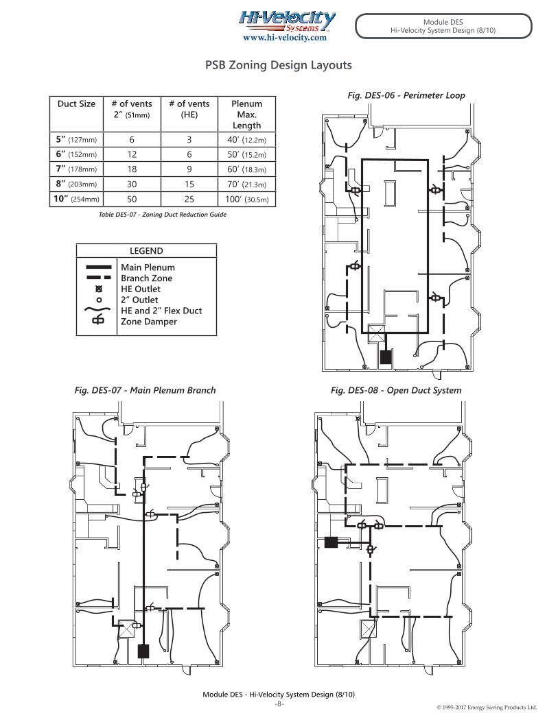
There are three basic layout styles to be used with the PSB Controller: the Perimeter Loop/Branch (Fig. DES-06), the Main Plenum Branch (Fig. DES-07), and the Open Duct standard design (Fig. DES-08).
The Open Duct layout is the same concept that is used on Page 6. This method utilizes the branch split and bullhead tees planning of air flow, with each zone being individually controlled.
When designing the perimeter loop, first determine the system load and individual zones. Locate the fan coil and vent outlets as per Page 5. Design the Perimeter Loop with the proper diameter 8” or 10” duct, as determined by the fan coil unit. Use appropriate plenum duct size around the perimeter of the structure.
When sizing the branch zone plenum off the Perimeter Loop, use the Zoning Duct Reduction Guide. (Table DES-06). Total the outlets for each individual zone to determine the zone plenum duct diameter. Locate the tee servicing this zone to minimize the zone plenum duct, and run the plenum where it’ll be possible to keep the AFD duct to 10’ and 15’ lengths. There is no minimum length on the Zone Main Plenum run. For maximum length allowed refer to the Zoning Duct Reduction Guide (Table DES-06).
The Perimeter Loop layout is as the term implies. A perimeter loop of plenum duct is installed in the structure, from there branch tees are installed for each zone dependant on the zone size, and a zone damper is installed for each take-off/zone.
The Main Plenum also requires that a comprehensive system load is completed, zones determined, fancoil and outlets located as per this design manual. The Plenum duct is then located to direct the air to the loads at each zone, and elbow and tees can be located where required, as per this design manual.
The zone duct diameter is determined from the duct reduction guide and an appropriate balanced tee installed. Locate the tee servicing this zone to minimize the zone plenum duct, and run the plenum where it’ll be possible to keep the AFD duct to 10’ and 15’ lengths. There is no minimum length on the Zone Main Plenum run. For maximum length allowed refer to the Zoning Duct Reduction Guide.
The Open Branch layout utilizes this layout on Page 6 in its entirety, from load calculation to duct location. This method is best suited when 2 - 4 zones are utilized, by following the design manual and duct reduction guide if necessary. You will either branch or bullhead the tees to 1 or 2 zones, and continue the plenum to the furthest run, installing zone dampers where required.
The Branch Take Offs easily form to ducts in the 6” to 10” range; extra care must be taken with smaller sized ducts to ensure a proper air seal. For tee reductions, keep the tee to the full duct size, reducing only after the tee. Keep the length of the smaller duct sizes to a minimum, since the duct loss is much higher. If a hole saw will be used to drill the branch take-off holes, metal ducts are recommended to be 28 gauge steel.
Layout Design
Perimeter Loop (Fig. DES-06)
Main Plenum Branch (Fig. DES-07)
Open Duct System (Fig. DES-08)
Quick acting, spring shut dampers are not to be used with the PSB Board. Instead, it is suggested to use a slow acting electronic damper, which gives the PSB controller adequate time to adjust to variations in duct pressure.
The PSB Board is compatible with most Forced Air Zoning Packages. Zoning control panels with a Recirculation Fan Option are strongly recommended, so as to utilize continuous air circulation for optimal Indoor Air Quality (IAQ) and Energy Efficiency. Independent testing has shown that utilizing the recirculation fan with the Hi-Velocity Systems VFD motor reduces total energy usage. This is due to less on/off cycling of AC and Heating equipment by constant de-stratification of the air.
PSB Zoning
PSB Zoning Design (HE-Z Series Only)
Module DESHi-Velocity System Design (7/10)
Please note: The HE-B Series Fan Coils can be used for zoning but may require the use of by-pass dampers or dump zones.
Shipping Weight (no coil) 85 lbs (38.6 Kg) 97 lbs (44 Kg) 111 lbs (50.3 Kg)
Fan Coil SizeLengthWidth
Height
32 5⁄16” (821mm)
14 1⁄2” (368mm)
18 1⁄4” (464mm)
32 5⁄16” (821mm)
19 1⁄2” (495mm)
18 1⁄4” (464mm)
32 5⁄16” (821mm)
25 1⁄2” (648mm)
18 1⁄4” (464mm)
-9-
F.L.A. - Full-Load AmperageRPM - Revolutions per MinuteE.S.P. - External Static PressureE.A.T. - Entering Air TemperaturedB/wB - Dry Bulb/Wet Bulb
TM
Energy Saving Products Ltd, established in 1983, manufactures the Hi-Velocity SystemsTM product line for residential, commercial and multi-family markets. Our facilities house Administration, Sales, Design, Manufacturing, as well as Research & Development complete with an in-house test lab. Energy Saving Products prides itself on Customer Service and provides design services and contractor support.
For all of your Heating, Cooling and Indoor Air Quality needs, the Hi-Velocity System is the right choice for you!
Phone: 780-453-2093 Fax: 780-453-1932
Toll Free: 1-888-652-2219
www.hi–velocity.com
Hi-Velocity HE-Z Fan Coils, Green TechnologyBuild Smart, Breathe Easy