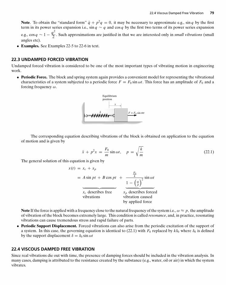
DYNAMICS STUDY PACK CHAPTER REVIEWS, FREE-BODY DIAGRAM WORKBOOK, COMPANION WEBSITE ENGINEERING MECHANICS DYNAMICS R. C. HIBBELER THIRTEENTH EDITION Upper Saddle River Boston Columbus San Francisco New York Indianapolis London Toronto Sydney Singapore Tokyo Montreal Dubai Madrid Hong Kong Mexico City Munich Paris Amsterdam Cape Town
Transcript
D Y N A M I C S S T U D Y P A C KCHAPTER REVIEWS, FREE-BODY DIAGRAM WORKBOOK, COMPANION WEBSITE
ENGINEERING MECHANICS
DYNAMICS
R. C. HIBBELER
THIRTEENTH EDITION
Upper Saddle River Boston Columbus San Francisco New York Indianapolis London Toronto Sydney Singapore Tokyo Montreal Dubai
Madrid Hong Kong Mexico City Munich Paris Amsterdam Cape Town
1 2 3 4 5 6 7 8 9 01
:01-NBSI :31-NBSI
Vice President and Editorial Director, ECS: notroH aicraM Acquisitions Editor: saiD nirroN Editorial Assistant: zeugirdoR ardnaS Managing Editor: onnasiD ttocS Art Director, Interior and Cover Designer: kceB ynneK Art Editor: selluD yrogerG Media Editor: nidnaS leinaD Operations Specialist: llewoDcM asiL Senior Marketing Manager: nagillaG miT Marketing Assistant: tnayrB noJ
yna yb ro mrof yna ni dettimsnart ro decudorper eb yam koob siht fo trap oN .devreser sthgir llA means, without permission in writing from the publisher.
.cnI ,noitacudE nosraeP fo kramedart a si ™llaH ecitnerP nosraeP
stroffe esehT .koob siht gniraperp ni stroffe tseb rieht desu evah koob siht fo rehsilbup dna rohtua ehT include the development, research, and testing of the theories and programs to determine their effectiveness. The author and publisher shall not be liable in any event for incidental or consequential damages with, or arising out of, the furnishing, performance, or use of these programs.
0-13-291129-9978-0-13-291129-0
ContentsWhat’s in This Package vi
Preface vii
� Part ISection-by-Section, Chapter-by-Chapter Summarieswith Review Questions and Answers 1
12 Kinematics of a Particle 3Main Goals of this Chapter: 3
12.1 Introduction 312.2 Rectilinear Kinematics: Continuous Motion 412.3 Rectilinear Kinematics: Erratic Motion 512.4 General Curvilinear Motion 512.5 Curvilinear Motion: Rectangular Components 612.6 Motion of a Projectile 712.7 Curvilinear Motion: Normal and Tangential Components 712.8 Curvilinear Motion: Cylindrical Components 812.9 Absolute Dependent Motion Analysis of Two Particles 912.10 Relative-Motion of Two Particles Using Translating Axes 10
Helpful Tips and Suggestions 11Review Questions 11
13 Kinetics of a Particle: Force and Acceleration 12Main Goals of this Chapter: 12
13.1 Newton’s Second Law of Motion 1213.2 The Equation of Motion 1313.3 Equation of Motion for a System of Particles 1313.4 Equations of Motion: Rectangular Coordinates 1313.5 Equations of Motion: Normal and Tangential Coordinates 1513.6 Equations of Motion: Cylindrical Coordinates 1613.7 Central-Force Motion and Space Mechanics 17
Helpful Tips and Suggestions 18Review Questions 18
14 Kinetics of a Particle: Work and Energy 19Main Goals of this Chapter: 19
14.1 The Work of a Force 1914.2 Principle of Work and Energy 2114.3 Principle of Work and Energy for a System of Particles 2214.4 Power and Efficiency 2214.5 Conservative Forces and Potential Energy 23
iii
iv Contents
14.6 Conservation of Energy 24Helpful Tips and Suggestions 24Review Questions 24
15 Kinetics of a Particle: Impulse and Momentum 25Main Goals of this Chapter: 25
15.1 Principle of Linear Impulse and Momentum 2515.2 Principle of Linear Impulse and Momentum for a System of Particles 2615.3 Conservation of Linear Momentum for a System of Particles 2715.4 Impact 2815.5 Angular Momentum 2915.6 Relation Between Moment of a Force and Angular Momentum 3015.7 Angular Impulse and Momentum Principles 3015.8 Steady Fluid Streams 3215.9 Propulsion with Variable Mass 32
Helpful Tips and Suggestions 33Review Questions 33
16 Planar Kinematics of a Rigid Body 34Main Goals of this Chapter: 34
16.1 Planar Rigid-Body Motion 3416.2 Translation 3516.3 Rotation about a Fixed Axis 3616.4 Absolute Motion Analysis 3816.5 Relative Motion Analysis: Velocity 3916.6 Instantaneous Center of Zero Velocity 3916.7 Relative-Motion Analysis:Acceleration 4116.8 Relative-Motion Analysis Using Rotating Axes 42
Helpful Tips and Suggestions 43Review Questions 43
17 Planar Kinetics of a Rigid Body: Force and Acceleration 44Main Goals of this Chapter: 44
17.1 Moment of Inertia 4417.2 Planar Kinetic Equations of Motion 4517.3 Equations of Motion: Translation 4617.4 Equations of Motion: Rotation About a Fixed Axis 4717.5 Equations of Motion: General Plane Motion 49
Helpful Tips and Suggestions 50Review Questions 50
18 Planar Kinetics of a Rigid Body: Work and Energy 51Main Goals of this Chapter: 51
18.1 Kinetic Energy 5118.2 The Work of a Force 5218.3 The Work of a Couple 5218.4 Principle of Work and Energy 5318.5 Conservation of Energy 53
Helpful Tips and Suggestions 54Review Questions 54
19 Planar Kinetics of a Rigid Body: Impulse and Momentum 55Main Goals of this Chapter: 55
19.1 Linear and Angular Momentum 55
Contents v
19.2 Principle of Impulse and Momentum 5719.3 Conservation of Momentum 5819.4 Eccentric Impact 59
Helpful Tips and Suggestions 59Review Questions 60
20 Three-Dimensional Kinematics of a Rigid Body 61Main Goals of this Chapter: 61
20.1 Rotation About a Fixed Point 6120.2 The Time derivative of a Vector Measured from Either a Fixed or Translating-Rotating System 6220.3 General Motion 6320.4 Relative-Motion Analysis Using Translating and Rotating Axes 63
Helpful Tips and Suggestions 64Review Questions 65
21 Three-Dimensional Kinetics of a Rigid Body 66Main Goals of this Chapter: 66
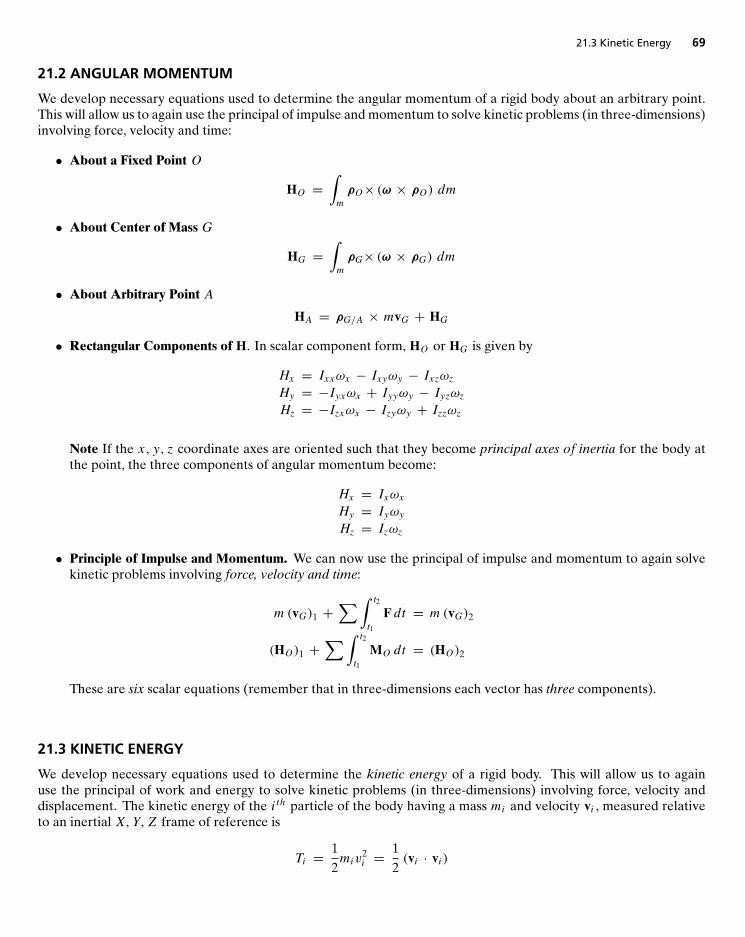
21.1 Moments and Products of Inertia 6621.2 Angular Momentum 6921.3 Kinetic Energy 6921.4 Equations of Motion 7021.5 Gyroscopic Motion 7221.6 Torque-Free Motion 74
Helpful Tips and Suggestions 75Review Questions 75
Helpful Tips and Suggestions 81Review Questions 81
ANSWERS TO REVIEW QUESTIONS 82
� Part II Free-Body Diagram Workbook 89
1 Basic Concepts in Dynamics 911.1 Equations of Motion 91
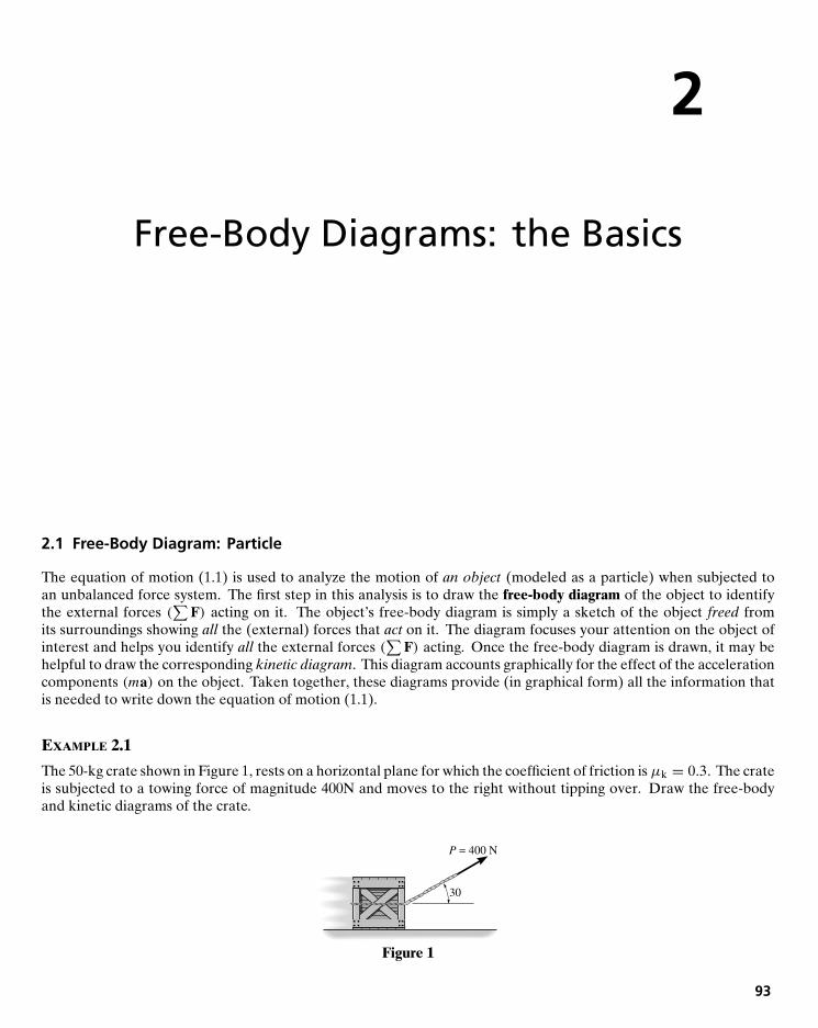
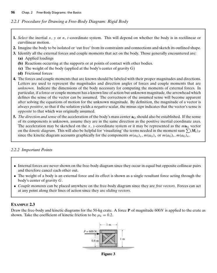
2 Free-Body Diagrams: the Basics 932.1 Free-Body Diagram: Particle 932.2 Free-Body Diagram: Rigid Body 95
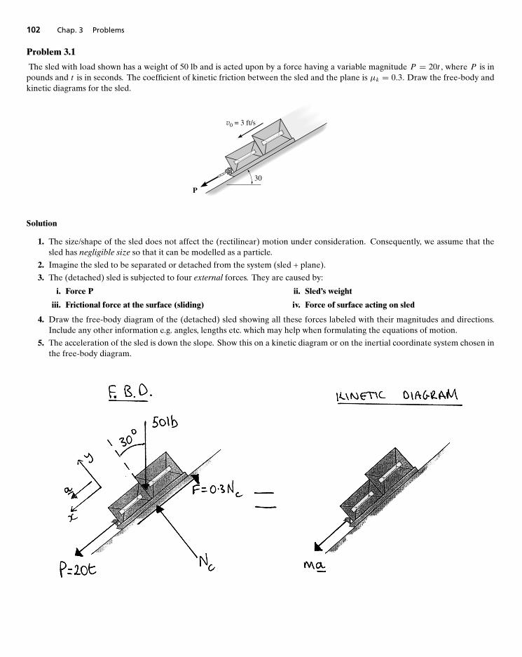
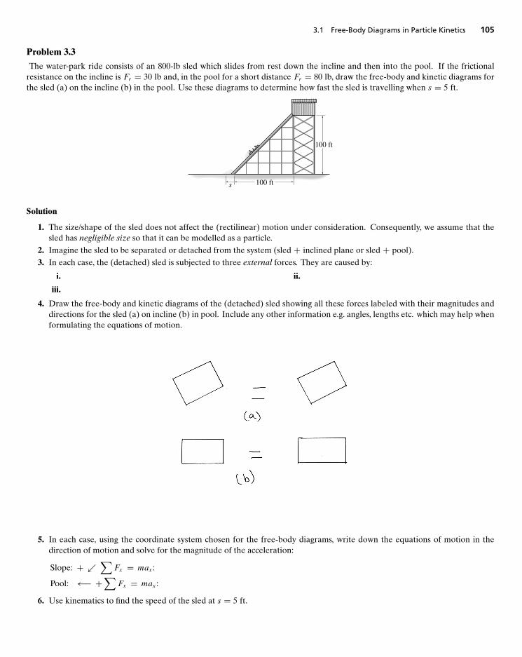
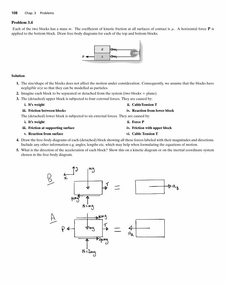
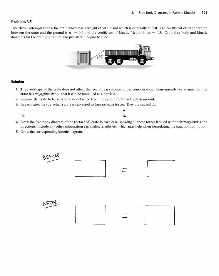
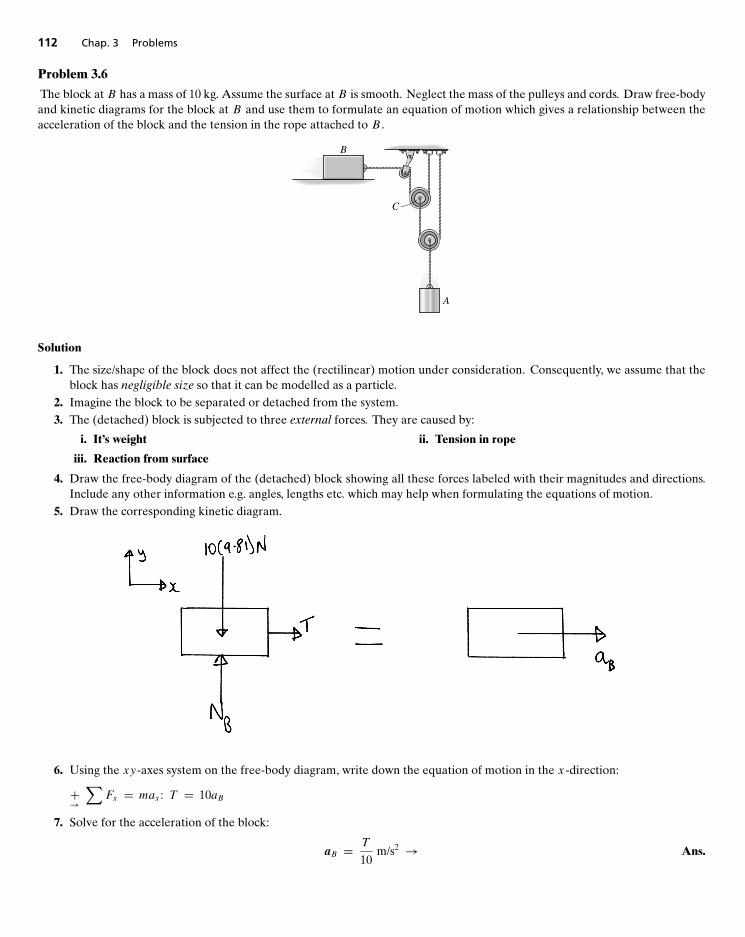
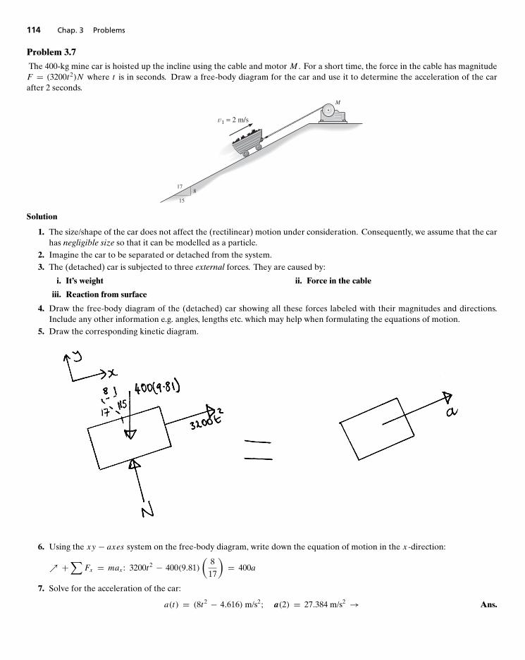
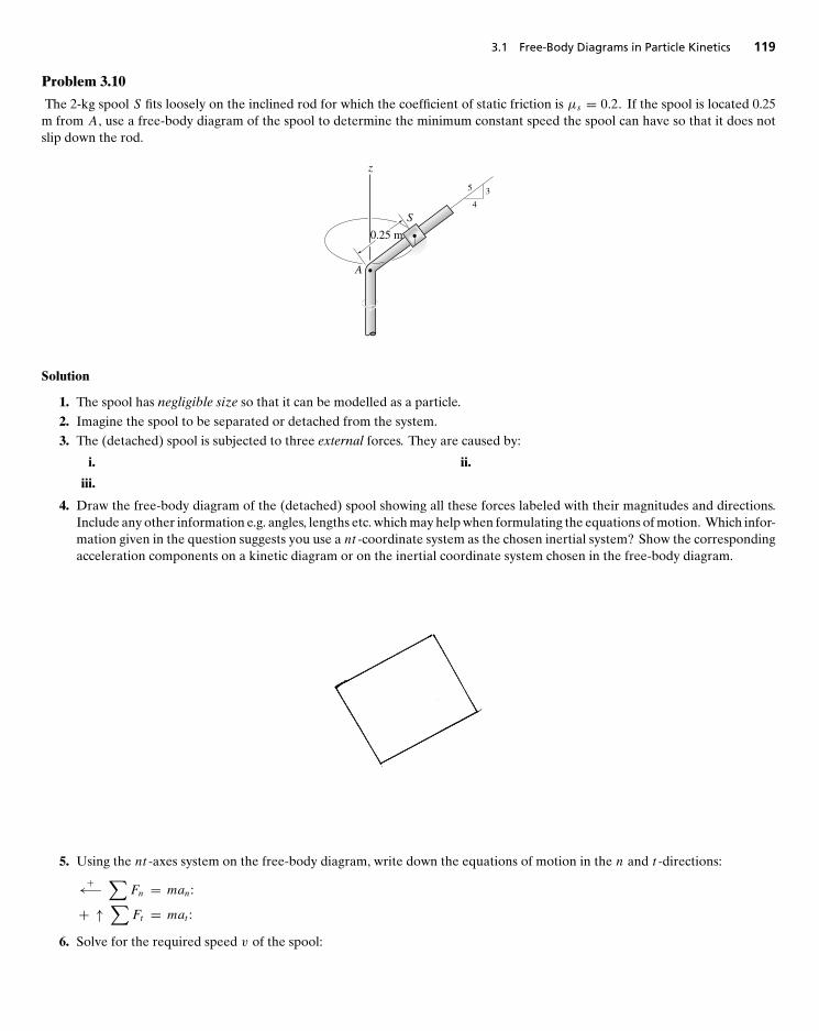
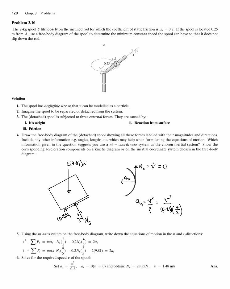
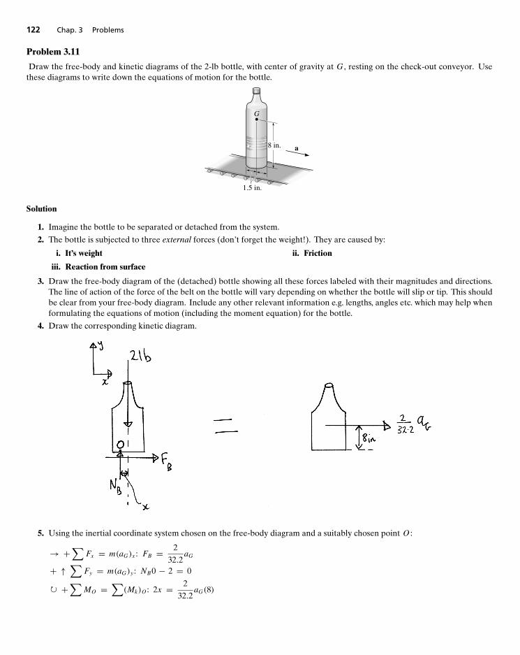
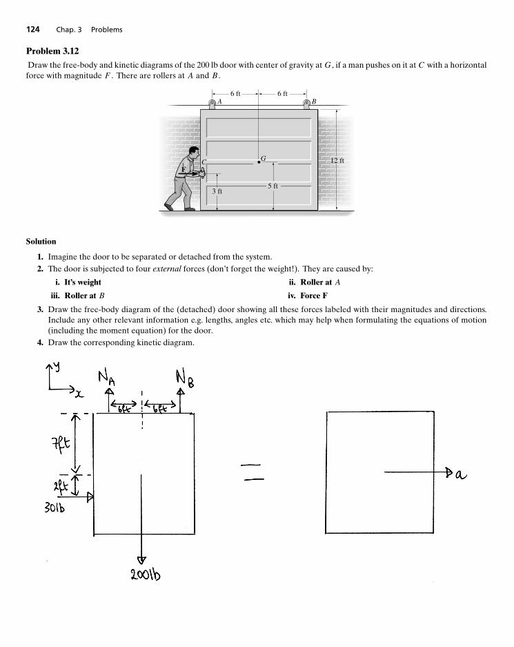
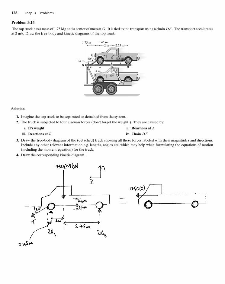
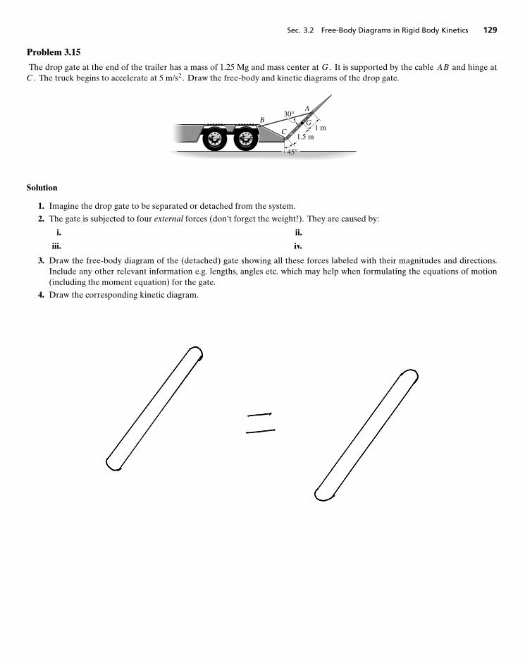
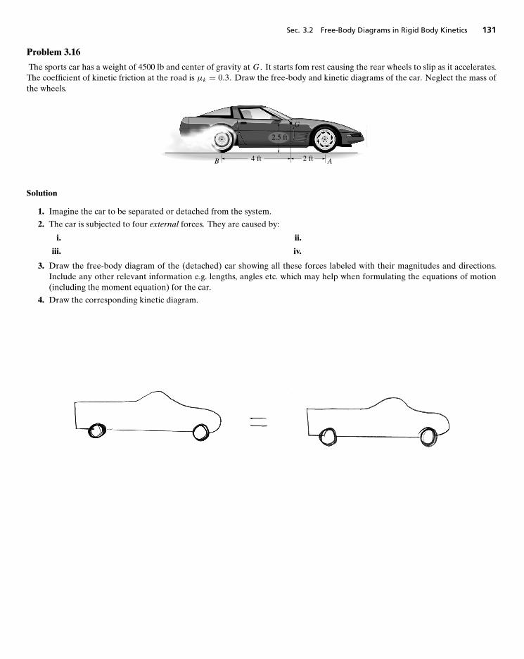
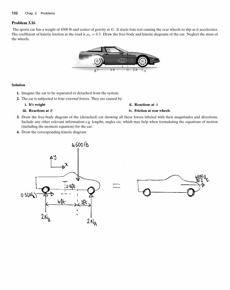
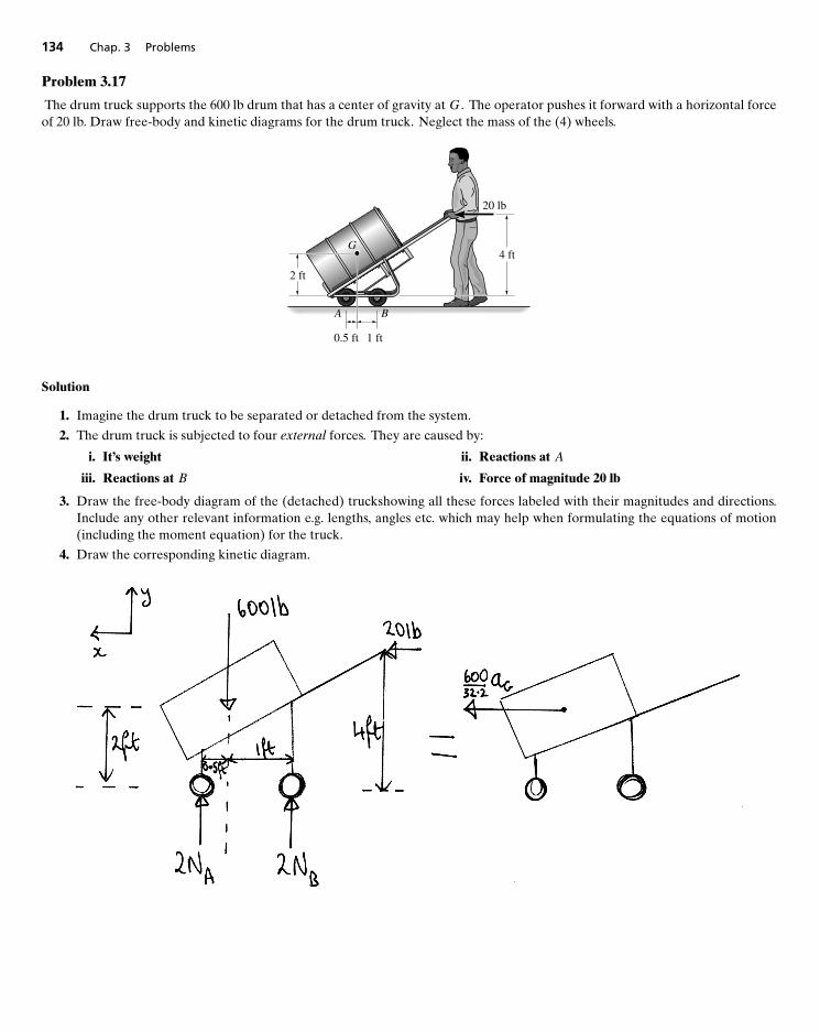
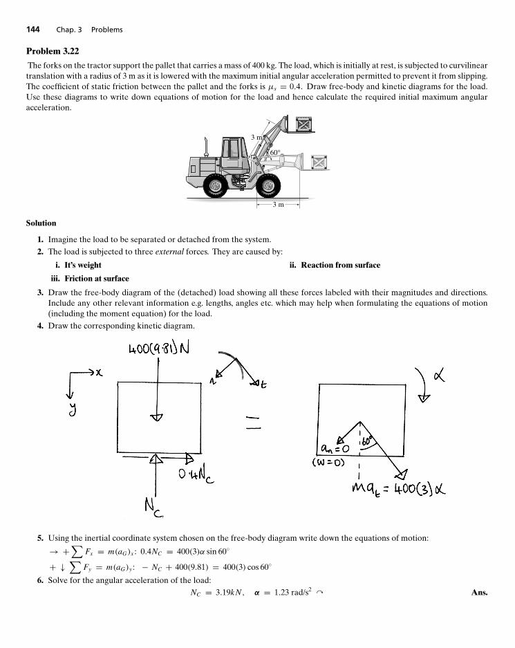
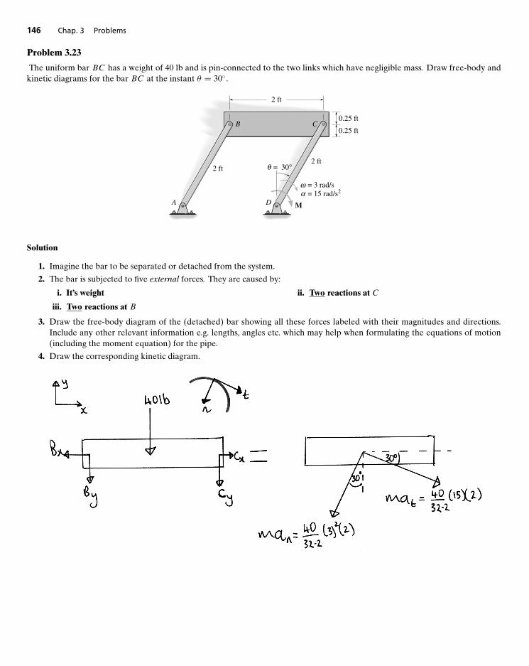
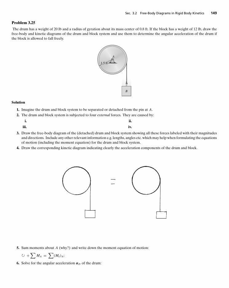
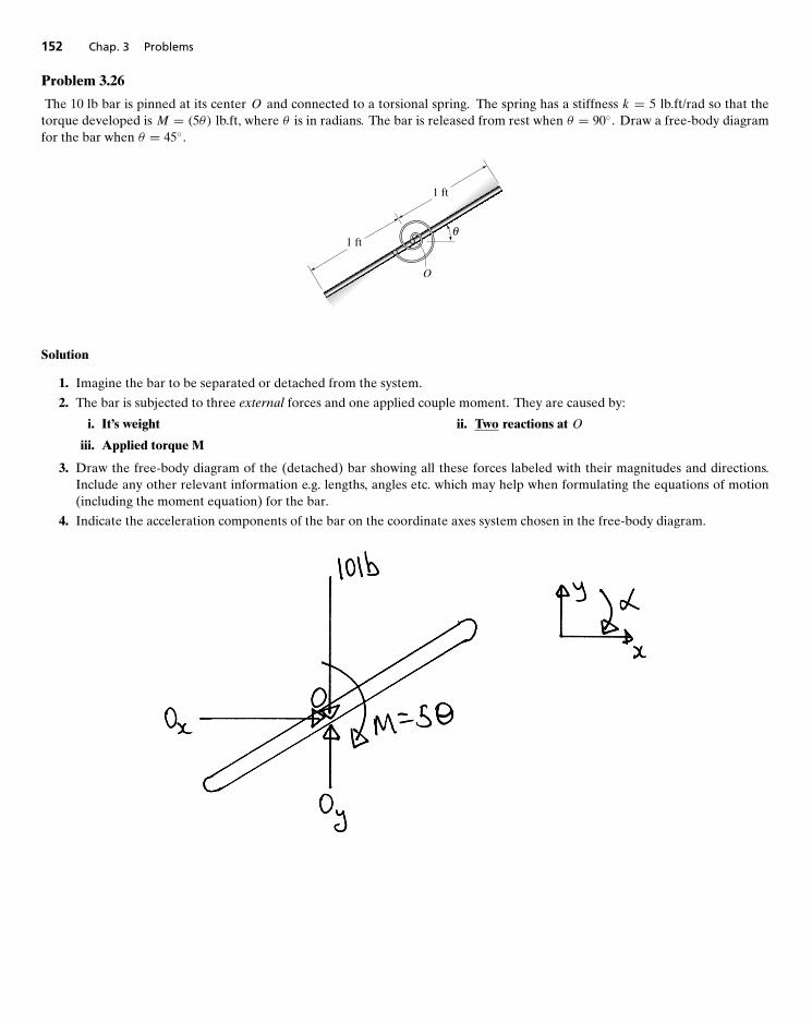
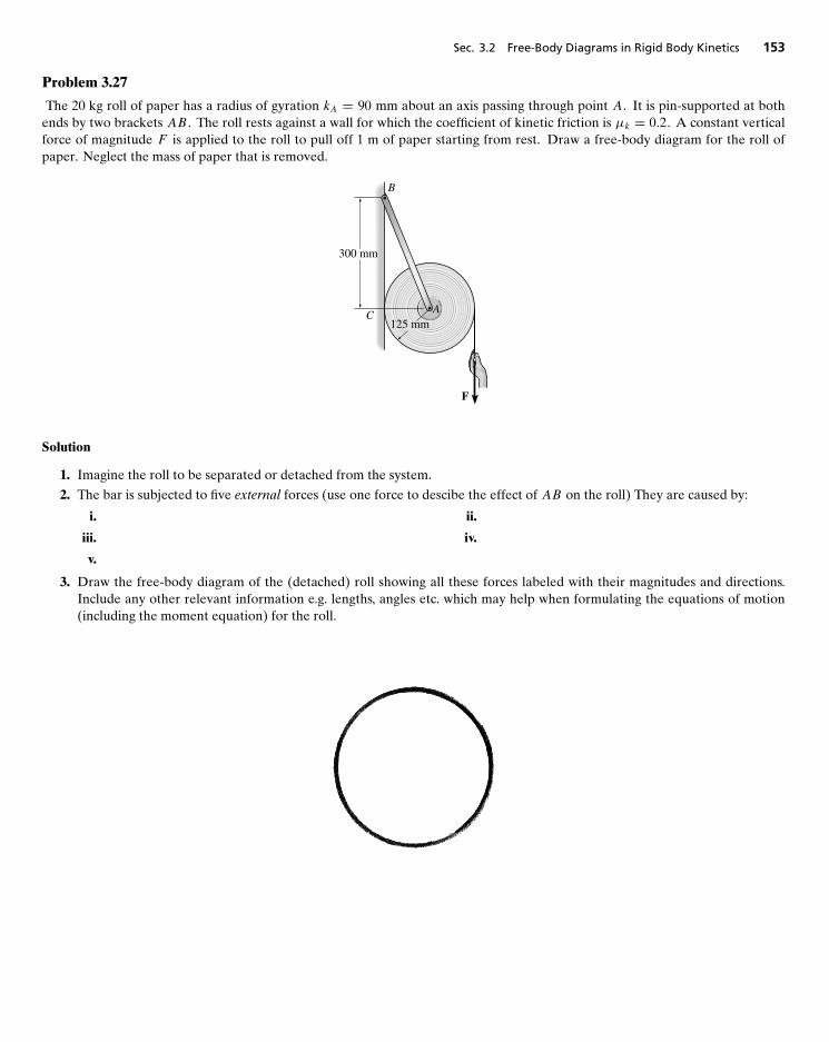
3 Problems 993.1 Free-Body Diagrams in Particle Kinetics 1013.2 Free-Body Diagrams in Rigid Body Kinetics 121
What’s in This Package
The Dynamics Study Pack was designed to help students improve their study skills. It consists of three studycomponents—a chapter-by-chapter review, a free-body diagram workbook, and an access code for the CompanionWebsite.
• Chapter-by-Chapter Review and Free-Body Diagram Workbook—Prepared by Peter Schiavone of the Universityof Alberta. This resource contains chapter-by-chapter Dynamics review, including key points, equations, andcheck up questions. The Free-Body Diagram Workbook steps students through numerous free-body diagramproblems that include full explanations and solutions.
• Companion Website — Located at www.pearsonhighered.com/hibbeler, the Companion Website includes thefollowing resources:
• Video Solutions — Complete, step-by-step solution walkthroughs of representative homework problemsfrom each section in the Dynamics text. Developed by Professor Edward Berger of University of Virginia,Video Solutions offer:
• Fully-worked Solutions — Showing every step of representative homework problems, to help studentsmake vital connections between concepts.
• Self-paced Instruction — Students can navigate each problem and select, play, rewind, fast-forward,stop, and jump-to sections within each problem’s solution.
• 24/7 Access — Help whenever students need it with over 20 hours of helpful review.
• 1000 Supplemental Statics and Dynamics Problems — A self-study resource, these supplemental problemshave complete solutions provided.
• MATLAB and Mathcad Tutorials — Focused on using MATLAB and Mathcad in Engineering Mechanics,these tutorials are keyed to the text.
To log in to the Companion Website, follow the instructions on the access card included with this study pack.
vi
PrefaceThis supplement is divided into two parts. Part I provides a section-by-section, chapter-by-chapter summary of the keyconcepts, principles and equations from R.C. Hibbeler’s text, Engineering Mechanics–Dynamics, Thirteenth Edition.Part II is a workbook which explains how to draw and use free-body diagrams when solving problems in Dynamics.
Part I: Chapter-by-Chapter Summaries
This part of the supplement provides a section-by-section, chapter-by-chapter summary of the key concepts, principlesand equations from R.C. Hibbeler’s text, Engineering Mechanics–Dynamics, Thirteenth Edition. We follow the samesection and chapter order as that used in the text and summarize important concepts from each section in easy-to-understand language. We end each chapter summary with a simple set of review questions designed to see if thestudent has understood the key concepts and chapter objectives.
This section of the supplement will be useful both as a quick reference guide for important concepts and equationswhen solving problems in, for example, homework assignments or laboratories and also as a handy review whenpreparing for any quiz, test, or examination.
Part II: Free-Body Diagram Workbook
A thorough understanding of how to draw and use a free-body diagram is absolutely essential when solvingproblems in mechanics.
This workbook consists mainly of a collection of problems intended to give the student practice in drawing and usingfree-body diagrams when solving problems in Dynamics.
All the problems are presented as tutorial problems with the solution only partially complete. The student isthen expected to complete the solution by “filling in the blanks” in the spaces provided. This gives the student theopportunity to build free-body diagrams in stages and extract the relevant information from them when formulatingequilibrium equations. Earlier problems provide students with partially drawn free-body diagrams and lots of hintsto complete the solution. Later problems are more advanced and are designed to challenge the student more. Thecomplete solution to each problem can be found on the back of the page. The problems are chosen from two-dimensional theories of particle and rigid body mechanics. Once the ideas and concepts developed in these problemshave been understood and practiced, the student will find that they can be extended in a relatively straightforwardmanner to accommodate the corresponding three-dimensional theories.
The workbook begins with a brief primer on free-body diagrams: where they fit into the general procedure ofsolving problems in mechanics and why they are so important. Next follows a few examples to illustrate ideas andthen the workbook problems.
For best results, the student should read the primer and then, beginning with the simpler problems, try tocomplete and understand the solution to each of the subsequent problems. The student should avoid the temptationto immediately look at the completed solution on the back of the page. This solution should be accessed only as alast resort (after the student has struggled to the point of giving up), or to check the student’s own solution after the
vii
viii Preface
fact. The idea behind this is very simple: we learn most when we do the thing we are trying to learn—reading throughsomeone else’s solution is not the same as actually working through the problem. In the former, the student gainsinformation, in the latter the student gains knowledge. For example, how many people learn to swim or drive a car byreading an instruction manual?
Consequently, since the workbook is based on doing, the student who persistently solves the problems in theworkbook will ultimately gain a thorough, usable knowledge of how to draw and use free-body diagrams.
PETER SCHIAVONE
PART I
Section-By-Section, Chapter-By-Chapter
Summaries with Review Questions and
Answers
12
Kinematics of a Particle
MAIN GOALS OF THIS CHAPTER:
• To introduce the concepts of position, displacement, velocity, and acceleration.
• To study particle motion along a straight line and represent this motion graphically.
• To investigate particle motion along a curved path using different coordinate systems.
• To present an analysis of dependent motion of two particles.
• To examine the principles of relative motion of two particles using translating axes.
12.1 INTRODUCTION
Mechanics is that branch of the physical sciences concerned with the behavior of bodies subjected to the action offorces. The subject of mechanics is divided into two parts:
• statics - the study of objects in equilibrium (objects either at rest or moving with a constant velocity).
• dynamics - the study of objects with accelerated motion.
� The subject of dynamics is often itself divided into two parts:
– kinematics - treats only the geometric aspects of the motion.
– kinetics - analysis of forces causing the motion.
• In this chapter, we study the kinematics of a particle - recall that a particle has a mass but negligible size andshape. Therefore, we limit discussion to those objects that have dimensions that are of no consequence in theanalysis of the motion. Such objects may be considered as particles, provided motion of the body is characterizedby motion of its mass center and any rotation of the body is neglected.
3
4 Chap. 12 Kinematics of a Particle
12.2 RECTILINEAR KINEMATICS: CONTINUOUS MOTION• Rectilinear Kinematics refers to straight line motion. The kinematics of a particle is characterized by specifying,
at any given instant, the particle’s position, velocity and acceleration.
– Position. The position of the particle is represented by an algebraic scalar s (the position coordinate).– Displacement. The displacement of the particle is a vector�r defined as the change in the particle’s position
vector r.– Velocity. The velocity of the particle is a vector .
∗ The average velocity is the displacement divided by time i.e., vavg = �r�t .
∗ The instantaneous velocity is v =drdt.
∗ Speed refers to the magnitude of velocity. and is written as v = |v| = dsdt.
∗ Average speed is the total distance divided by the total time (different from average velocity which isdisplacement divided by time).
– Acceleration. The acceleration of the particle is a vector a = dvdt. It’s magnitude is written as a = dv
dt= d2s
dt2.
∗ In rectilinear kinematics, the acceleration is negative when the particle is slowing down or decelerating.∗ A particle can have an acceleration and yet have zero velocity.
∗ The relationship ads = vdv is derived from a = dvdt
and v = dsdt
by eliminating dt .
CONSTANT ACCELERATION
• Let a = ac = constant. Assume that v = v0 and s = s0 at time t = 0. Then
v = v0 + act (speed as a function of time), (12.0)
s = s0 + v0t + 12act
2 (position as a function of time), (12.1)
v2 = v20 + 2ac (s − s0) (speed as a function of position). (12.2)
PROCEDURE FOR SOLVING PROBLEMS
The equations of rectilinear kinematics should be applied as follows:
• Coordinate System
– Establish a position coordinate s along the path and specify its fixed origin and positive direction.– Since motion is along a straight line, the particle’s position, velocity and acceleration can be represented as
algebraic scalars. For analytical work, the sense of s , v and a is then determined from their algebraic signs.– The positive sense for each scalar can be indicated by an arrow shown alongside each kinematic equation
as it is applied.
• Kinematic Equations.
– If a relationship is known between any two of the four variables a, v, s and t, then a third variable can beobtained by using one of the kinematic equations a = dv
dt, v = ds
dtor ads = vdv, which relates all three
variables.– Whenever integration is performed, it is important that the position and velocity be known at a given
instant in order to evaluate either the constant of integration if an indefinite integral is used, or the limitsof integration if a definite integral is used.
– Note that Eqs. (12.0)–(12.2) apply only when the acceleration is constant.
12.4 General Curvilinear Motion 5
12.3 RECTILINEAR KINEMATICS: ERRATIC MOTION
When a particle’s motion during a time period is erratic, it may be difficult to obtain a continuous function to describeits position, velocity or acceleration. Instead, the motion may best be described graphically using a series of curvesthat can be generated experimentally by computer. There are several frequently occurring situations:
• Given s− t Graph, Construct v− t Graph.If the position of a particle can be plotted over time (s− t graph), theparticle’s velocity as a function of time (v − t graph) can be obtained by measuring the slope of the s − t graph.
ds
dt= v
slope of s − t graph = velocity
• Given v− t Graph, Construct a− t Graph. When the particle’s v− t graph is known, the particle’s accelerationas a function of time (a − t graph) can be obtained by measuring the slope of the v − t graph.
dv
dt= a
slope of v − t graph = acceleration
• Given a − t Graph, Construct v − t Graph. When the particle’s a − t graph is given, the v − t graph may beconstructed by:
�v =∫a dt
change in velocity = area under a − t graph
• Given v − t Graph, Construct s − t Graph. When the particle’s v − t graph is given, the s − t graph may beconstructed by:
�s =∫v dt
displacement = area under v − t graph
• Given a− s Graph, Construct v− s Graph. When the particle’s a− s graph can be constructed, the v− s graphmay be obtained:
12
(v2
1 − v20
) = ∫ s1
s0
a ds
= area under a − s graph
• Given v − s Graph, Construct a − s Graph. When the particle’s v − s graph is known the acceleration at anyposition s can be obtained:
a = vdv
dsacceleration = velocity × slope of v − s graph
12.4 GENERAL CURVILINEAR MOTION
Curvilinear motion occurs when the particle moves along a curved path.
6 Chap. 12 Kinematics of a Particle
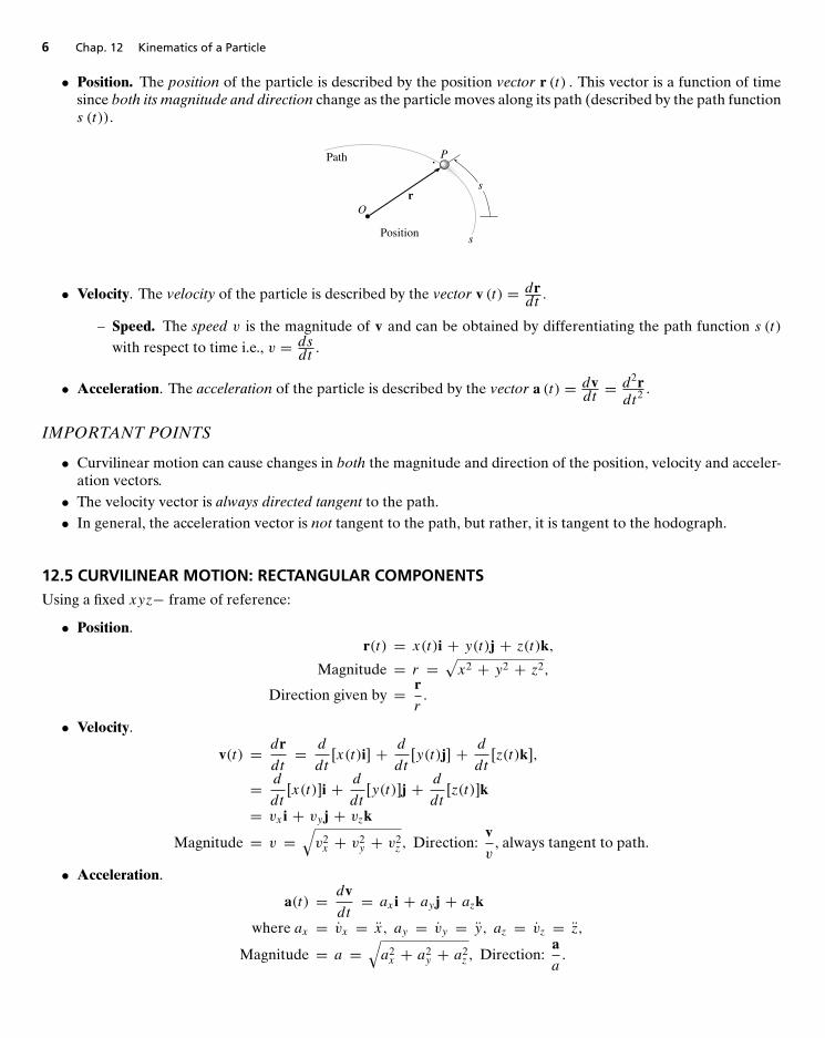
• Position. The position of the particle is described by the position vector r (t) . This vector is a function of timesince both its magnitude and direction change as the particle moves along its path (described by the path functions (t)).
s
P
rO
Path
Position s
• Velocity. The velocity of the particle is described by the vector v (t) = drdt.
– Speed. The speed v is the magnitude of v and can be obtained by differentiating the path function s (t)with respect to time i.e., v = ds
dt.
• Acceleration. The acceleration of the particle is described by the vector a (t) = dvdt= d2rdt2
.
IMPORTANT POINTS
• Curvilinear motion can cause changes in both the magnitude and direction of the position, velocity and acceler-ation vectors.• The velocity vector is always directed tangent to the path.• In general, the acceleration vector is not tangent to the path, but rather, it is tangent to the hodograph.
12.5 CURVILINEAR MOTION: RECTANGULAR COMPONENTSUsing a fixed xyz− frame of reference:
• Position.r(t) = x(t)i + y(t)j + z(t)k,
Magnitude = r =√x2 + y2 + z2,
Direction given by = r
r.
• Velocity.
v(t) = dr
dt= d
dt[x(t)i] + d
dt[y(t)j] + d
dt[z(t)k],
= d
dt[x(t)]i + d
dt[y(t)]j + d
dt[z(t)]k
= vx i + vyj + vzkMagnitude = v =
√v2x + v2
y + v2z , Direction:
v
v, always tangent to path.
• Acceleration.
a(t) = dv
dt= ax i + ayj + azk
where ax = vx = x, ay = vy = y, az = vz = z,
Magnitude = a =√a2x + a2
y + a2z , Direction:
a
a.
12.7 Curvilinear Motion: Normal and Tangential Components 7
12.6 MOTION OF A PROJECTILEThe free-flight motion of a projectile is often studied in terms of its rectangular components, since the projectile’sacceleration always acts in the vertical direction.
PROCEDURE FOR SOLVING PROBLEMS
• Coordinate System
– Establish the fixed x, y coordinate axes and sketch the trajectory of the particle. Between any two pointson the path specify the problem data and the three unknowns. In all cases the acceleration of gravityacts downward. The particle’s initial and final velocities should be represented in terms of their x and ycomponents.
– Remember that positive and negative position, velocity and acceleration components always act in accor-dance with their associated coordinate directions.
• Kinematic Equations
– Depending upon the known data and what is to be determined, a choice should be made as to which threeof the following four equations should be applied between the two points on the path to obtain the mostdirect solution to the problem.
• Horizontal Motion
– The velocity in the horizontal or x direction is constant i.e., (vx) = (v0)x and
x = x0 + (v0)x t.
• Vertical Motion
– In the vertical or y−direction only two of the following three equations can be used for solution:
vy = (v0)y − act,y = y0 + (v0)yt + 1
2act
2,
v2y = (v0)
2y + 2ac (y − y0) .
– For example, if the particle’s final velocity vy is not needed, then the first and third of these equations(for y) will not be useful.
12.7 CURVILINEAR MOTION: NORMAL AND TANGENTIALCOMPONENTS
IMPORTANT POINTS
Coordinate System
• Provided the path of the particle is known, we establish a set of n and t coordinates having a fixed origin whichis coincident with the particle at the instant considered.• The positive tangent axis always acts in the direction of motion and the positive normal axis is directed towards
the path’s center of curvature.• The n and t axes are particularly advantageous for studying the velocity and acceleration of the particle, because
the velocity v and the acceleration a are expressed by the equations
v = vut , v = s, (12.3)a = atut + anun, (12.4)
8 Chap. 12 Kinematics of a Particle
at = v or atds = vdv, (12.5)
an = v2
ρ. (12.6)
Velocity
• The particle’s velocity is always tangent to the path.• The magnitude of velocity (speed) is found from the time derivative of the path function v = s.
Tangential Acceleration
• The tangential component of acceleration is the result of the time rate of change in the magnitude of velocity.This component acts in the positive s−direction if the particle’s speed is increasing or in the opposite directionif the speed is decreasing.• The relations between at v and s are the same as for rectilinear motion:
at = v, atds = vdv.
• If at is constant, at = (at )c, the above equations, when integrated, yield
s = s0 + v0t + 12(at )c t
2
v = v0 + (at )c tv2 = v2
0 + 2(at )c(s − s0)
Normal Acceleration
• The normal component of acceleration is the result of the time rate of change in the direction of the particle’svelocity. This component is always directed toward the center of curvature of the path i.e., along the positive naxis.
• The magnitude of this component is determined from an = v2
ρ .
• If the path is expressed as y = f (x) , the radius of curvature ρ at any point on the path is determined from theequation
ρ = [1 + (dy/dx)2]32∣∣∣∣d2y
dx2
∣∣∣∣.
12.8 CURVILINEAR MOTION: CYLINDRICAL COMPONENTSIn some problems it is often convenient to express the path of motion in terms of cylindrical coordinates r, θ, z. Ifmotion is restricted to the plane, polar coordinates r and θ are used.
IMPORTANT POINTS
Coordinate System
• Polar coordinates are particularly suitable for solving problems for which data regarding the angular motion ofthe radial coordinate r is given to describe the particle’s motion.• To use polar coordinates, the origin is established at a fixed point, and the radial line r is directed to the particle.• The transverse coordinate θ is measured counterclockwise from a fixed reference line to the radial line.
12.9 Absolute Dependent Motion Analysis of Two Particles 9
O
P
r
r
ur
θ
uθ
θ
Position
Position, Velocity and Acceleration
• The position of the particle is defined by the position vector r = rur .• The velocity and acceleration of the particle are given, respectively, by
v = vrur + vθuθa = arur + aθuθ
• Once r and the four time derivatives r , r, θ , and θ have been evaluated at the instant considered, their valuescan be substituted into the following equations to obtain the radial and transverse components of v and a.
• If it is necessary to take the time derivatives of r = f (θ) , it is very important to use the chain rule.• Motion in three-dimensions requires a simple extension of the above formula to
Position: r = rur + zuz,Velocity: v = rur + rθuθ + zuz,
Acceleration: a = (r − rθ2)ur + (rθ + 2r θ )uθ + zuz.• Note: If the particle travels in a circular path, r = constant so that r = r = 0 and the formulas (12.7)–(12.8)
simplify considerably.
12.9 ABSOLUTE DEPENDENT MOTION ANALYSIS OF TWOPARTICLESIn some problems, the motion of one particle will depend on the corresponding motion of another particle. Thisdependency commonly occurs if the particles are interconnected by inextensible cords which are wrapped aroundpulleys. When each particle moves along a rectilinear path, itudes of the velocity and acceleration of the particles willchange, not their line of direction. The following procedure can be used:
PROCEDURE FOR SOLVING PROBLEMS
• Position-Coordinate Equation
– Establish position coordinates which have their origin located at a fixed point or datum.– The coordinates are directed along the path of motion and extend to a point having the same motion as
each of the particles.– It is not necessary that the origin be the same for each of the coordinates; however, it is important that each
coordinate axis selected be directed along the path of motion of the particle.– Using geometry or trigonometry, relate the coordinates to the total length of the cord, lT or to that portion
of cord, l , which excludes the segments that do not change length as the particles move - such as arc segments
10 Chap. 12 Kinematics of a Particle
wrapped over pulleys.
– If a problem involves a system of two or more cords wrapped around pulleys, then the position of a pointon one cord must be related to the position of a point on another cord. Separate equations are written fora fixed length of each cord of the system and the positions of the two particles are then related by theseequations.
• Time Derivatives
– Two successive time derivatives of the position-coordinate equations yield the required velocity and accel-eration equations which relate the motions of the particles.
– The signs of the terms in these equations will be consistent with those that specify the positive and negativesense of the position coordinates.
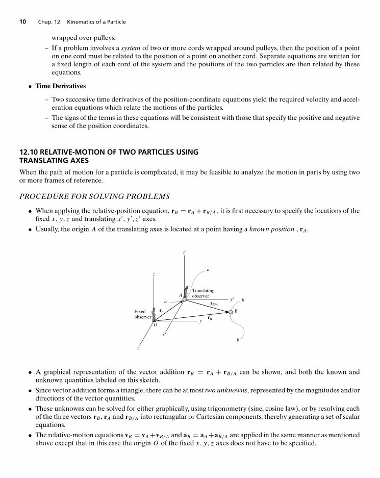
12.10 RELATIVE-MOTION OF TWO PARTICLES USINGTRANSLATING AXES
When the path of motion for a particle is complicated, it may be feasible to analyze the motion in parts by using twoor more frames of reference.
PROCEDURE FOR SOLVING PROBLEMS
• When applying the relative-position equation, rB = rA+ rB/A, it is first necessary to specify the locations of thefixed x, y, z and translating x ′, y ′, z′ axes.
• Usually, the origin A of the translating axes is located at a point having a known position , rA.
z'
z
A
O
x'
x
y
y'
rB
rA
rB/A
Translatingobserver
a
a
b
b
Fixedobserver
B
• A graphical representation of the vector addition rB = rA + rB/A can be shown, and both the known andunknown quantities labeled on this sketch.
• Since vector addition forms a triangle, there can be at most two unknowns, represented by the magnitudes and/ordirections of the vector quantities.
• These unknowns can be solved for either graphically, using trigonometry (sine, cosine law), or by resolving eachof the three vectors rB, rA and rB/A into rectangular or Cartesian components, thereby generating a set of scalarequations.
• The relative-motion equations vB = vA+vB/A and aB = aA+aB/A are applied in the same manner as mentionedabove except that in this case the origin O of the fixed x, y, z axes does not have to be specified.
REVIEW QUESTIONS 11
HELPFUL TIPS AND SUGGESTIONS• The most effective way to learn the principles of dynamics is to solve problems - in a logical and orderly manner
(practice is the key!).• Remember that in solving problems from engineering mechanics you are solving real practical problems and
producing real data with physical significance. Thus, you are responsible for making sure your results are correct,consistent and well-presented. Get into the habit of doing this now so that it will become second nature by thetime you graduate. In the world of professional engineering you have a responsibility to your profession and tothe many people that will use the product you will help to design, manufacture or implement.
REVIEW QUESTIONS
1. Can the kinematics of a particle can be regarded as the same as the kinematics of a point?2. Is the velocity of a point always tangent to its path?3. Is the acceleration of a point always tangent to its path?4. If a ball is travelling in a horizontal circle at constant speed, does the center of the ball have zero acceleration?5. Is the velocity of a point independent of the reference frame chosen to express the position of the point?6. When does the acceleration of a particle always have a zero normal component?7. If a particle in rectilinear motion has zero speed at some instant in time, is the acceleration necessarily zero at
the same instant?8. Can a particle have r = 0 but still have a nonvanishing radial component of acceleration?
13
Kinetics of a Particle:
Force and Acceleration
MAIN GOALS OF THIS CHAPTER:• To state Newton’s Laws of Motion and Gravitational attraction and to define mass and weight.• To analyze the accelerated motion of a particle using the equation of motion with different coordinate systems.• To investigate central-force motion and apply it to problems in space mechanics.
13.1 NEWTON’S SECOND LAW OF MOTION• Newton’s second law of motion states that the unbalanced force on a particle causes it to accelerate. If the mass
of the particle is m and its velocity is v, the second law can be written as:
F = d
dt(mv) = ma. (13.0)
Equation (13.0) is referred to as the equation of motion and is one of the most important formulations inmechanics. It’s validity is based solely on experimental evidence.• Newton’s Law of Gravitational Attraction: The mutual attraction between any two particles is given by
F = Gm1m2
r2
where F is the force of attraction between the two particles, G is the universal constant of gravitation (G =66.73(10−12)m3/(kg ·s2)), m1,m2 is the mass of each of the two particles and r is the distance between the centersof the two particles.• Mass and Weight.
Mass is a property of matter that provides a quantitative measure of its resistanceto a change in velocity (see Equation(13.0)). Mass is an absolute quantity.
Weight is a force that is caused by the earth’s gravitation. It is not absolute;rather it depends on the altitude of the mass from the earth’s surface.
The relationship between the weight W and mass m of a particle is given by W = mg where g represents theacceleration due to gravity.
12
13.4 Equations of Motion: Rectangular Coordinates 13
• SI System of Units. In the SI system, the mass of a body is specified in kilograms (kg) and the weight in Newtons(N) i.e.,
W = mg (N) (g = 9.81 m/s2).
• FPS System of Units. In the FPS system, the weight is specified in pounds (lb) and the mass in slugs (slug). i.e.,
m = W
g(slug) (g = 32.2f t/s) .
13.2 THE EQUATION OF MOTION
• When more than one force acts on a particle, the resultant force is determined by a vector summation of all theforces i.e., FR =
∑F. For this more general case, the equation of motion (13.0) may be written as∑
F = ma. (13.1)
The magnitude and direction of each force acting on the particle (left-hand side of Equation (13.1) are identifiedusing a free-body diagram. A kinetic diagram identifies the magnitude and direction of the vectorma (right-handside of Equation (13.1)).
• Inertial Frame. Whenever the equation of motion (13.0) or (13.1) is applied, it is required that measurements ofthe acceleration be made from a Newtonian or inertial frame of reference.
A Newtonian or inertial frame of reference does not rotate and is either fixedor translates in a given direction with a constant velocity (zero acceleration).
13.3 EQUATION OF MOTION FOR A SYSTEM OF PARTICLES
• The sum of the external forces acting on a system of particles is equal to the total mass m of the particles timesthe acceleration of its center of mass G i.e., ∑
F = maG. (13.2)
SUMMARY
The equation of motion (13.0)–(13.2) is based on experimental evidenceand is valid only when applied from an inertial frame of reference.
13.4 EQUATIONS OF MOTION: RECTANGULAR COORDINATES
• When a particle is moving relative to an inertial x, y, z frame of reference, the (vector) equation of motion (13.1)is equivalent to the following three scalar equations:
∑Fx = max,∑Fy = may, (13.3)∑Fz = maz.
14 Chap. 13 Kinetics of a Particle: Force and Acceleration
Only the first two of these equations are used to specify the motion of a particle constrained to move only in thex − y plane.
SOLVING PROBLEMS USING THE EQUATIONS OFMOTION (13.3)
• Free-Body Diagram
– Select the inertial coordinate system. Rectangular or x, y, z coordinates are used to analyze problemsinvolving rectilinear motion.
– Draw the particle’s free-body diagram. This makes it possible to resolve all the forces acting on the particleinto their x, y, z components (for use in Equations (13.3).
– The direction and sense of the particle’s acceleration a should also be established. If the senses of itscomponents are unknown, assume they are in the same direction as the positive inertial coordinate axes.
– The acceleration may be represented as the ma vector on the kinetic diagram.
– Identify the unknowns in the problem.
• Equations of Motion
– If the forces can be resolved directly from the free-body diagram, apply Equations (13.3).
– If the geometry of the problem appears complicated, which often occurs in three dimensions, Cartesianvector analysis can be used for the solution.
– Friction. If the particle contacts a rough surface, it may be necessary to use the frictional equation Ff =μkN. Remember that Ff always acts to oppose the motion of the particle relative to the surface it contacts.
– Spring. If the particle is connected to an elastic spring having negligible mass, the spring force Fs can berelated to the deformation of the spring by the equation Fs = ks.
• Kinematics
– If the velocity or position of the particle is to be found, it will be necessary to apply the proper kinematicequations once the particle’s acceleration is determined from Equation (13.3).
– If acceleration is a function of time, use a = dvdt
and v = dsdt
, which, when integrated, yield the particle’sspeed and position.
– If acceleration is a function of displacement, integrate ads = vdv to obtain the speed as a function ofposition.
– If acceleration is constant, use v = v0 + act, s = s0 + v0t + 12act
2, v2 = v20 + 2ac (s − s0) to determine the
speed or position of the particle.
– If the problem involves the dependent motion of several particles, use the procedure of Section 12.9 torelate their accelerations.
– In all cases, make sure the positive inertial coordinate directions used for writing the kinematic equationsare the same as those used for writing the equations of motion; otherwise, simultaneous solution of theequations will result in errors.
– If the solution for an unknown vector component yields a negative scalar, it indicates that the componentacts in the direction opposite to that which was assumed.
• See Examples13-1 to 13-5 in text.
13.5 Equations of Motion: Normal and Tangential Coordinates 15
13.5 EQUATIONS OF MOTION: NORMAL AND TANGENTIALCOORDINATES
• When a particle moves over a known curved path, the equation of motion for the particle may be written in thetangential, normal and binormal directions giving the following three scalar equations of motion:∑
Ft = mat ,∑Fn = man, (13.4)∑Fb = 0.
b
tO
n ΣFnun
ΣFbub
ΣFtut
P
Inertial coordinatesystem
SOLVING PROBLEMS USING THE EQUATIONS OFMOTION (13.4)
When a problem involves the motion of a particle along a known curved path, normal and tangential coordinatesshould be considered for the analysis since the acceleration components can be readily formulated. Specifically, fort, n and b coordinates we have the following procedure:
• Free-Body Diagram
– Establish the inertial t, n, b coordinate system at the particle and draw the particle’s free-body diagram.
– The particle’s normal acceleration an always acts in the positive n direction.
– If the tangential direction at is known, assume it acts in the positive t direction.
– Identify the unknowns in the problem.
• Equations of Motion
– Apply the equations of motion (13.4).
• Kinematics
– Formulate the tangential and normal components of acceleration: i.e., at = dvdt
or at = v dvds and an = v2
ρ .
– If the path is defined as y = f (x) , the radius of curvature at the point where the particle is located can beobtained from
ρ =
[1 +
(dydx
)2] 3
2
∣∣∣∣d2y
dx2
∣∣∣∣.
16 Chap. 13 Kinetics of a Particle: Force and Acceleration
13.6 EQUATIONS OF MOTION: CYLINDRICAL COORDINATES
• The equation of motion for the particle may be written in the (cylindrical) r, θ, z directions giving the followingthree scalar equations of motion: ∑
Fr = mar,∑Fθ = maθ, (13.5)∑Fz = maz.
θ
O
r
z
P
Σ Fzuz
F u θ θ
Frur
Inertial coordinate system
Σ
Σ
Note that if the particle is constrained to move only in the r − θ plane, then only the first two of Eqs. (13.5) are usedto specify the motion.
SOLVING PROBLEMS USING THE EQUATIONS OFMOTION (13.5)
Cylindrical or polar coordinates are a suitable choice for the analysis of a problem for which data regarding theangular motion of the radial line r are given, or in cases where the path can be conveniently expressed in terms ofthese coordinates. Once these coordinates have been established, the equations of motion can be applied in order torelate the forces acting on the particle to its acceleration components. The specific procedure is as follows:
• Free-Body Diagram
– Establish the inertial r, θ, z coordinate system at the particle and draw the particle’s free-body diagram.– Assume that ar , aθ , az act in the positive directions of r, θ, z if they are unknown.– Identify the unknowns in the problem.
• Equations of Motion
– Apply the equations of motion (13.5).
• Kinematics
– Determine r and the time derivatives r , r, θ , θ , z, and then evaluate the acceleration components ar =r − rθ2, aθ = rθ + 2r θ , az = z.
– If any of the acceleration components is computed as a negative quantity, it indicates that it acts in itsnegative coordinate direction.
– Use the chain rule of calculus to calculate the time derivatives of r = f (θ) .
13.7 Central-Force Motion and Space Mechanics 17
13.7 CENTRAL-FORCE MOTION AND SPACE MECHANICS
If a particle is moving only under the influence of a force having a line of action which is always directed toward afixed point, the motion is called central-force motion. This type of motion is commonly caused by electrostatic andgravitational forces.
• The following differential equation defines the path r = f (θ) over which the particle travels when it is subjectedto the central force F (taken positive when it is directed towards the fixed point):
d2ξ
dθ2+ ξ = F
mh2ξ 2(13.6)
where ξ = 1r , m is the mass of the particle and h is constant.
• When F is the force of gravitational attraction e.g., between an artificial satellite and the earth, we have F =GMem
r2 , where Me and m represent the mass of the earth and the satellite, respectively, G is the gravitational
constant and r is the distance between the mass centres. The solution of (13.6) in this case is
ξ = 1r= C cos (θ − φ) + GMe
h2(13.7)
where C and φ are arbitrary (determined from the data obtained for the position and velocity of the satellite).Equation (13.7) represents free-flight trajectory of the satellite - notice that Equation (13.7) is the equation of aconic section in polar coordinates.
• The type of (conical) path taken by the satellite is determined from the value of the eccentricity e = Ch2
GMeof
the conic section described by Equation (13.7):
e = 0 free-flight trajectory is a circlee = 1 free-flight trajectory is a parabolae < 1 free-flight trajectory is an ellipsee > 1 free-flight trajectory is a hyperbola
v0
v0 < vc
Crashtrajectory Circular
trajectory
Elliptical trajectory
Parabolic trajectory
Hyperbolic trajectorye > 1
e = 1
e < 1
e = 0
r0
18 Chap. 13 Kinetics of a Particle: Force and Acceleration
• The initial launch velocity required for the satellite to follow a parabolic path (on the border of never returningto its initial starting point) is called the escape velocity. The corresponding speed is given by
ve =√
2GMe
r0.
• The speed vc required to launch a satellite into a circular orbit is given by
vc =√GMe
r0
Speeds at launch less than vc will cause the satellite to reenter the earth’s atmosphere and either burn up orcrash.
• All trajectories attained by planets and most satellites are elliptical. For a satellite’s orbit about the earth, theminimum distance r0 from the orbit to the center of the earth is called the perigee of the orbit. The maximumdistance is called the apogee.
• In addition to predicting the orbital trajectory of earth satellites, the above theory is also valid in predicting themotion of the planets travelling around the sun (again the solution of Equation (13.6) but with F the force of
gravitational attraction between a planet and the sun, i.e., F = GMsm
r2 , where Ms is the mass of the sun). The
fact that planets do indeed follow elliptic orbits about the sun was discovered by Johannes Kepler in the earlyseventeenth century - after 20 years of planetary observation! This led to Kepler’s laws for planetary motion.
HELPFUL TIPS AND SUGGESTIONS
• Remember the importance of a free-body diagram in formulating the equation of motion - in any coordinatesystem.
REVIEW QUESTIONS
1. True or False?
(a) The equation of motion is not valid without the assumption of an inertial frame.
(b) The equation of motion is based solely on mathematical arguments.
2. What are the (scalar) equations of motion if a particle is constrained to move only in the x − y plane?
3. When is it preferable for the equation of motion of a particle to be written in normal and tangential coordinates?Why?
4. In Equations (13.4) above, why is there no motion of the particle in the binormal direction?
5. When is it preferable for the equation of motion of a particle to be written in cylindrical coordinates?
6. Do all central force problems result in paths which are conics?
7. In a gravitational central force problem, how do we determine the type of conic describing the path?
8. What method did Johannes Kepler use to discover that planets follow elliptic orbits around the sun?
14
Kinetics of a Particle:
Work and Energy
MAIN GOALS OF THIS CHAPTER:• To develop the principle of work and energy and apply it to solve problems that involve force, velocity and
displacement.• To study problems that involve power and efficiency.• To introduce the concept of a conservative force and apply the theorem of conservation of energy to solve kinetic
problems.
14.1 THE WORK OF A FORCEIn mechanics a force F does work on a particle only when the particle undergoes a displacement in the direction of theforce.
• The work dU done by the force F in displacing a particle dr is a scalar quantity defined by
dU = F · dr = Fds cos θ
where ds = |dr| and θ is the angle between the tails of dr and F.• Work of a Variable Force. If a particle undergoes a finite displacement along its path from r1 to r2 or s1 to s2
the work done is given by
U1−2 =∫ r2
r1
F · dr =∫ s2
s1
F cos θ ds (14.0)
• Work of a Constant Force Moving Along a Straight Line. Since both F and θ are constant (straight line path)
U1−2 = F cos θ
∫ s2
s1
ds
= F cos θ (s2 − s1)
Fc
θ
Fc cos θ s2s1s
19
20 Chap. 14 Kinetics of a Particle: Work and Energy
• Work of a Weight W.
U1−2 = −Wy (14.1)
where the vertical displacement y is measured positive upward (so the work of the weight is positive if the particleis displaced downward and negative if displaced upward).
• Work of a Spring Force.
(a) Work of a Spring. The work of a spring is of the form Us = 12ks
2, where k is the spring stiffness and s is thestretch or compression of the spring.
(b) Work Done ON the Spring. If a spring is elongated or compressed from a position s1 to a further positions2, the work done on the spring by the force Fs developed in the (linearly elastic) spring is positive, since, ineach case, the force and displacement are in the same direction. Then
U1−2 = 12k(s2
2 − s21
)(14.2)
Fs
s1s2
ds
ds
s
s
k
k
Unstretchedposition, s = 0
Force onSpring
Fs
(c) Work Done on a Body (or Particle) Attached to a Spring. In this case, the force Fs exerted on the body isopposite to that exerted on the spring. Hence, the force Fs will do negative work on the body (particle):
U1−2 = −12k(s2
2 − s21
)(14.3)
Unstretchedposition, s = 0
Fs
s
Force onParticle
k
14.3 Principle of Work and Energy for a System of Particles 21
14.2 PRINCIPLE OF WORK AND ENERGY
• The principle of work and energy for a particle is described by the equation
T1 +∑
U1−2 = T2 (14.4)
where T1 = 12mv
21 and T2 = 1
2mv22 represent the kinetic energy of the particle at point1 and point2, respectively,
while∑U1−2 represents the work done by all the forces acting on the particle as the particle moves from point
1 to point 2..
• The principle of work and energy is used to solve kinetic problems that involve velocity, force and displacement(since these terms are involved in the equation describing the principle i.e., Equation (14.4)).
SOLVING PROBLEMS USING THE PRINCIPLE OFWORK AND ENERGY
• Work (Free-Body Diagram)
– Establish the inertial coordinate system and draw a free-body diagram of the particle in order to accountfor all the forces that do work on the particle as it moves along its path.
• Principle of Work and Energy
– Apply the principle of work and energy, T1 +∑U1−2 = T2.
– The kinetic energy at the initial and final points is always positive, since it involves the speed squared(T = 1
2mv2).
– A force does work when it moves through a displacement in the direction of the force.
– Work is positive when the force component is in the same direction as its displacement, otherwise it isnegative.
– Forces that are functions of displacement must be integrated to obtain the work (see Equation (14.0)).Graphically, the work is equal to the area under the force-displacement curve.
– The work of a weight is the product of the weight magnitude and the vertical displacement, UW = ±Wy(see Equation (14.1)). It is positive when the weight moves downwards and negative when the weightmoves upwards.
– The work of a spring is of the form Us = 12ks
2, where k is the spring stiffness and s is the stretch orcompression of the spring (see also Equations (14.2) and (14.3).
14.3 PRINCIPLE OF WORK AND ENERGY FOR A SYSTEM OFPARTICLES
• The principle of work and energy can be extended to include a system of particles isolated within an enclosedregion of space. Symbolically, the principle looks like∑
T1 +∑
U1−2 =∑
T2. (14.5)
In words, this equations states that
the system’s initial kinetic energy (∑
T1) plus the work done by all the
external and internal forces acting on the particles of the system (∑
U1−2) is equal
to the system’s final kinetic energy (∑
T2).
22 Chap. 14 Kinetics of a Particle: Work and Energy
Note that although the internal forces on adjacent particles occur in equal but opposite collinear pairs, the totalwork done by each of these forces will, in general, not cancel out since the paths over which correspondingparticles travel will be different. There are two important exceptions to this rule which often occur in practice:
– When Particles are Contained Within the Boundary of a Translating Rigid Body.– When Particles are Connected by Inextensible Cables. In these cases, adjacent particles exert equal but
opposite internal forces that have components which undergo the same displacement, and therefore thework of these forces cancels.
• Special Class of Problems Involving Work of Friction Caused by Sliding. We note also that Equation (14.5) canbe applied to problems involving sliding friction; however, it should be realized that the work of the resultantfrictional force is not represented by μkNs; instead, this term represents both the external work of friction(μkNs ′) and internal work (μkN(s − s ′)) which is converted into various forms of internal energy, such as heat.
14.4 POWER AND EFFICIENCY• Power. Power is defined as the amount of work performed per unit of time. Hence, the power P generated by a
machine or engine which performs an amount of work dU within a time interval dt , is given by
P = dU
dt
= F · dr
dt= F · v
where v is the velocity of the point which is acted upon by the force F.
– Consequently power is a scalar with basic units watt (W) in the SI system and horsepower (hp) in the FPSsystem.
1W = 1J/s = 1N · m/s1hp = 550f t · lb/s1hp = 746W
• Efficiency. The mechanical efficiency of a machine is defined by
ε = power outputpower input
or
ε = energy outputenergy input
Since machines consist of a series of moving parts, frictional forces will always be developed within the machine.As a result, extra energy or power is needed to overcome these forces. Consequently, the efficiency of a machineis always less than one.
COMPUTING THE POWER SUPPLIED TO A BODY
• First determine the external force F acting on the body which causes the motion. This force is usually developedby a machine or engine placed either within or external to the body.• If the body is accelerating, it may be necessary to draw its free-body diagram and apply the equation of motion
(∑
F = ma) to determine F.• Once F and the velocity v of the point where F is applied have been found, the power is determined by multiplying
the force magnitude by the component of velocity acting in the direction of F i.e., P = F · v = Fv cos θ.
• In some problems, the power may be found by calculating the work done by F per unit of time (Pavg = �U�t or
P = dUdt).
14.6 Conservation of Energy 23
14.5 CONSERVATIVE FORCES AND POTENTIAL ENERGY
• Conservative Force. When the work done by a force in moving a particle from one point to another is independentof the path followed by the particle, then this force is called a conservative force. e.g.,
– The work done by the weight of a particle is independent of the path of the particle i.e., the work donedepends only on particle’s vertical displacement.
– The work done by a spring force acting on a particle is independent of the path of the particle i.e., it dependsonly on the extension or compression of the spring.
– In contrast, we note that the force of friction exerted on a moving object by a fixed surface depends onthe path of the object i.e., the longer the path, the greater the work. Consequently, frictional forces arenonconservative. The work is dissipated from the body in the form of heat.
• Potential Energy. Potential energy is a measure of the amount of work a conservative force will do when it movesfrom a given position to a reference datum.
– Gravitational Potential Energy. The gravitational potential energy of a particle of weight W is
Vg = Wy,
where y is the position of the particle measured positive upward from an arbitrarily selected datum.
– Elastic Potential Energy. The elastic potential energy due to a spring’s configuration (stretched or com-pressed a distance s from its unstretched position) is
Ve = 12ks2
Note that Ve is always positive since, in the deformed position, the force of the spring has the capacity foralways doing positive work on the particle when the spring is returned to its unstretched position.
• Potential Function. In general, if a particle is subjected to both gravitational and elastic forces, the particle’spotential energy can be expressed as a potential function, which is the algebraic sum
V = Vg + Ve.• Proving a Force F is Conservative. In fact, a force F is related to its potential function V by the equation
F = −∇V (14.6)
In other words if a force F and its potential function Vsatisfy Equation (14.6), then F is a conservative force.
14.6 CONSERVATION OF ENERGY
• If only conservative forces are applied to a body, the principle of work and energy becomes the principle ofconservation of (mechanical) energy described by:
T1 + V1 = T2 + V2. (14.7)
In other words, during the motion, the sum of the particle’s kinetic and potential energies remains constant (i.e.,kinetic energy must be transformed into potential energy and vice versa during the motion).
• System of Particles. If a system of particles is subjected to only conservative forces, the equation of conservationof energy for the system is ∑
T1 +∑
V1 =∑
T2 +∑
V2 (14.8)
24 Chap. 14 Kinetics of a Particle: Work and Energy
SOLVING PROBLEMS USING THE CONSERVATIONOF ENERGY (14.7)
The conservation of energy equation is used to solve problems involving velocity, displacement and conservative forcesystems. It is generally easier to apply than the principle of work and energy because the energy equation just requiresspecifying the particle’s kinetic and potential energies at only two points along the path, rather than determining thework done when the particle moves through a displacement. The procedure is as follows:
• Potential Energy
– Draw two diagrams showing the particle located at its initial and final points along the path.– If the particle is subjected to a vertical displacement, establish the fixed horizontal datum from which to
measure the particle’s gravitational potential energy Vg.– Data pertaining to the elevation y of the particle from the datum and the extension or compression s of
any connecting springs can be determined from the geometry associated with the two diagrams.– Recall Vg = Wy, where y is positive upward from the datum and negative downward from the datum; alsoVe = 1
2ks2.
• Conservation of Energy
– Apply the equation T1 + V1 = T2 + V2.
– When determining the kinetic energy, T = 12mv
2, the particle’s speed v must be measured from an inertialreference frame.
HELPFUL TIPS AND SUGGESTIONS• Only problems involving conservative forces (weights and springs) may be solved using conservation of energy
(Equations (14.7) or (14.8)). Friction or other drag-resistant forces, which depend on velocity or acceleration arenonconservative (a portion of the work done by such forces is transformed into thermal energy which dissipatesinto the surroundings and may not be recovered). When such forces enter into the problem, use the principle ofwork and energy.
REVIEW QUESTIONS
1. How would you calculate the work done by a force F?2. When is the principle of work and energy used to solve kinetic problems?3. How is power defined and how is it calculated?4. Why is the efficiency of a machine always less than one?5. What is a conservative force? Give some examples of conservative forces.6. Explain why the weight of an object is a conservative force.7. Give an example of a nonconservative force and explain why the force is nonconservative.8. What is potential energy? Give some examples.9. How can you prove that a force is conservative?
10. When is the conservation of energy equation used to solve problems in kinetics?
15
Kinetics of a Particle:
Impulse and Momentum
MAIN GOALS OF THIS CHAPTER:
• To develop the principle of linear impulse and momentum for a particle.
• To study the conservation of linear momentum for particles.
• To analyze the mechanics of impact.
• To introduce the concept of angular impulse and momentum.
• To solve problems involving steady fluid streams and propulsion with variable mass.
15.1 PRINCIPLE OF LINEAR IMPULSE AND MOMENTUM
• The principle of linear impulse and momentum is obtained from a time integration of the equation of motionand is described by the equation
mv1 +∑∫ t2
t1
F dt = mv2. (15.0)
– Linear Momentum. Each of the two vectors of the form L = mv is referred to as the particle’s linearmomentum. It’s magnitude is mv and its direction is the same as that of the velocity v.
– Linear Impulse. The integral I = ∫ F dt is referred to as the linear impulse. This is a vector quantity whichmeasures the effect of a force during the time the force acts. The impulse acts in the same direction as theforce F and has units of force-time e.g., N · s or lb · s.
• The principle of linear impulse and momentum (15.0) states that the initial momentum of the particle plus thesum of all the impulses applied to the particle is equivalent to the final momentum of the particle. It provides adirect means of obtaining the particle’s final velocity v2 after a specified time period when the particle’s initialvelocity is known and the forces acting on the particle are either constant or can be expressed as functions oftime.
25
26 Chap. 15 Kinetics of a Particle: Impulse and Momentum
• Principle of Linear Impulse and Momentum in Scalar Form.
m(vx)1 +∑∫ t2
t1
Fx dt = m(vx)2 ,
m(vy)
1 +∑∫ t2
t1
Fy dt = m(vy)
2 , (15.1)
m(vz)1 +∑∫ t2
t1
Fz dt = m(vz)2 .
PROCEDURE FOR SOLVING PROBLEMS
The principle of linear impulse and momentum is used to solve problems involving force, time and velocity.
• Free-Body Diagram
– Establish the x, y, z inertial frame of reference and draw the particle’s free-body diagram in order toaccount for all the forces that produce impulses on the particle.
– The direction and sense of the particle’s initial and final velocities should be established.
– If a vector is unknown, assume that the sense of its components is in the direction of the positive inertialcoordinates.
– As an alternative procedure, draw the impulse and momentum diagrams for the particle.
• Principle of Linear Impulse and Momentum
– In accordance with the established coordinate system apply the principle (15.0). If motion occurs in the x−yplane, the two scalar component equations (see Equations (15.1)) can be formulated by either resolving thevector components of F from the free-body diagram or by using the data on the impulse and momentumdiagrams.
– Realize that all forces acting on the particle’s free-body diagram will create an impulse, even though someof these forces will do no work.
– Forces that are functions of time must be integrated to obtain the impulse.
– If the problem involves the dependent motion of several particles, use Section 12.9 to relate their velocities.Make sure the positive coordinate directions used for writing these kinematic equations are the same asthose used for writing the equations of impulse and momentum.
15.2 PRINCIPLE OF LINEAR IMPULSE AND MOMENTUM FOR ASYSTEM OF PARTICLES
• The principle of linear impulse and momentum for a system of particles moving relative to an inertial referenceis given by ∑
mi(vi )1 +∑∫ t2
t1
Fi dt =∑
mi(vi )2 (15.2)
which states that the initial linear momenta of the system plus the impulses of all the external forces acting onthe system from t1 to t2 are equal to the system’s final linear momentum.
• Alternatively, in terms of the mass center G of the system, we have
m(vG)1 +∑∫ t2
t1
F dt = m(vG)2. (15.3)
15.3 Conservation of Linear Momentum for a System of Particles 27
15.3 CONSERVATION OF LINEAR MOMENTUM FOR A SYSTEMOF PARTICLES• When the sum of the external impulses acting on a system of particles is zero, Equation (15.2) becomes∑
mi(vi )1 =∑
mi(vi )2 (15.4)
which expresses conservation of linear momentum i.e., that the linear momenta for a system of particles remainconstant during the time period t1 to t2.• In terms of the mass center G of the system, we have
(vG)1 = (vG)2.
That is, the velocity vG of the mass center for the system of particles does not change when no external impulsesare applied to the system.• For application, a careful study of the free-body diagram for the entire system of particles should be made to
identify the forces which create external impulses and thereby determine in which direction linear momentumis conserved.
– If the time period over which the motion is studied is very short, some of the external impulses may alsobe neglected or considered approximately equal to zero. The forces causing these negligible impulsesare called nonimpulsive forces e.g., weight of a body or any force which is very small compared to otherlarger (impulsive) forces (which change the system’s momentum drastically). When making the distinctionbetween impulsive and nonimpulsive forces, it is important to realize that this applies only during the (veryshort) time interval t1 to t2.
PROCEDURE FOR SOLVING PROBLEMS
Generally, the principle of linear impulse and momentum or the conservation of linear momentum is applied to asystem of particles in order to determine the final velocities of the particles just after the time period considered. Byapplying these equations to the entire system, the internal impulses acting within the system, which may be unknown,are eliminated from the analysis.
• Free-Body Diagram
– Establish the x, y, z inertial frame of reference and draw the free-body diagram for each particle of thesystem in order to identify the internal and external forces.
– The conservation of linear momentum applies to the system in a given direction when no external forcesor if nonimpulsive forces act on the system in that direction.
– Establish the direction and sense of the particles’ initial and final velocities. If the sense is unknown, assumeit is along a positive inertial coordinate axis..
– As an alternative procedure, draw the impulse and momentum diagrams for each particle of the system.
• Momentum Equations
– Apply the principle of linear impulse and momentum or the conservation of linear momentum in theappropriate directions.
– If it is necessary to determine the internal impulse∫
F dt acting on only one particle of a system, then theparticle must be isolated (free-body diagram), and the principle of linear impulse and momentum must beapplied to the particle.
– After the impulse is calculated, and provided the time �t for which the impulse acts is known, the average
impulsive force Favg can be determined from Favg =
∫F dt
�t .
• See Examples 15.4 to 15.8 in text.
28 Chap. 15 Kinetics of a Particle: Impulse and Momentum
15.4 IMPACTImpact occurs when two bodies collide with each other during a very short period of time, causing relatively large(impulsive) forces to be exerted between the bodies. In general, there are two types of impact:
• Central Impact - when the direction of motion of the mass centers of the two colliding particles is along a line(line of impact) passing through the mass centers of the particles.• Oblique Impact - when the motion of one or both of the particles is at an angle with the line of impact.
COEFFICIENT OF RESTITUTION
The coefficient of restitution is defined as the ratio of the relative velocity of the particles’ separation just after impact,to the relative velocity of the particles’ approach just before impact i.e.,
e = (vB)2 − (vA)2(vA)1 − (vB)1
.
• Elastic Impact: e = 1. Deformation impulse is equal and opposite to restitution impulse.• Plastic Impact: e = 0. No restitution impulse so that after collision, both particles stick together and move with
a common velocity.
PROCEDURE FOR SOLVING PROBLEMS (CentralImpact)
In most cases, the final velocities of two smooth particles are to be determined just after they are subjected to directcentral impact. Provided the coefficient of restitution, the mass of each particle, and each particle’s initial velocity justbefore impact are known, the solution to the problem can be obtained using the following two equations:
• The conservation of momentum applies to the system of particles:∑mv1 =
∑mv2.
• The coefficient of restitution e relates the relative velocities of the particles along the ,line of impact, just beforeand just after collision.
PROCEDURE FOR SOLVING PROBLEMS (ObliqueImpact)
When oblique impact occurs between two smooth particles, the particles move away from each other with velocitieshaving unknown directions as well as unknown magnitudes. Provided the initial velocities are known, four unknownsare present in the problem. These unknowns may be represented either as (vA)2 , (vB)2 , θ2, and φ2, or as the x andy components of the final velocities.
Line of impact
(vA)1
BA
(vB)1
θ φ
Plane of contact
(vA)2 (vB)2
θ φ
y
x
1
2 2
1
1
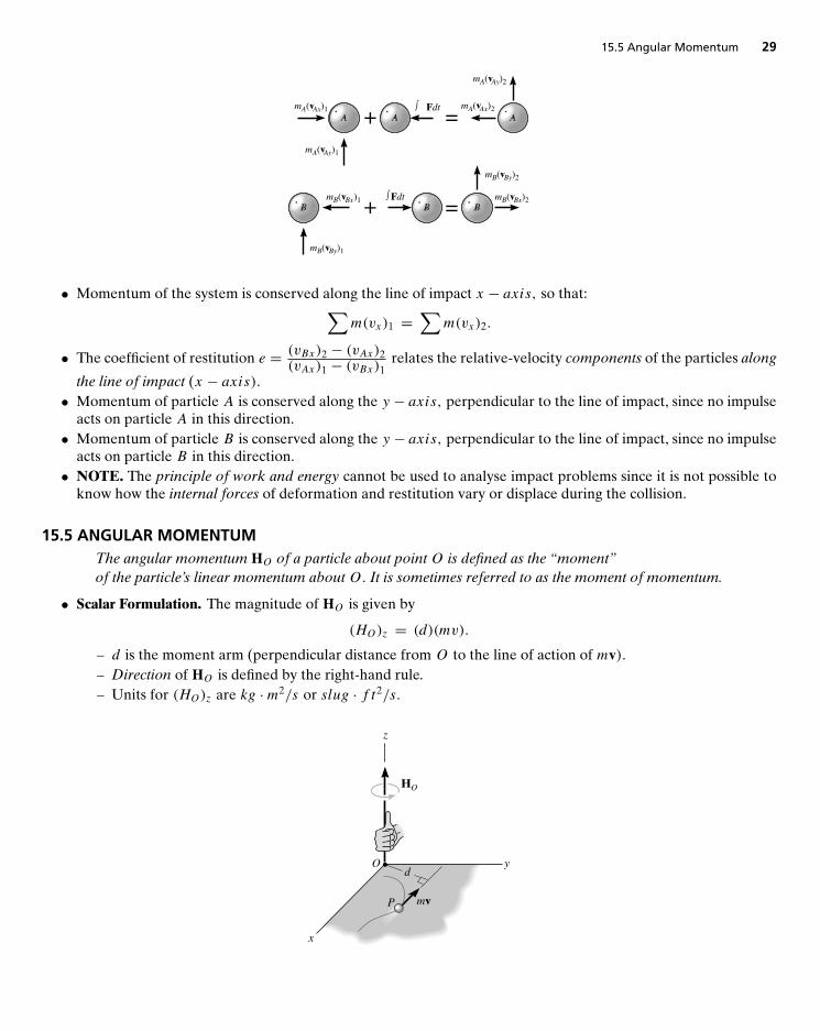
If the y− axis is established within the plane of contact and the x− axis along the line of impact, the impulsiveforces of deformation and restitution act only in the x direction. Resolving the velocity or momentum vectors intocomponents along the x and y axes, it is possible to write four independent scalar equations in order to determine(vAx)2 ,
(vAy)
2 , (vBx)2 and(vBy)
2 .
15.5 Angular Momentum 29
mA(vAx)1
mA(vAy)1
Fdt+
+
=
=
A A AmA(vAx)2
mA(vAy)2
B
mB(vBy)1
mB(vBx)1B
FdtB
mB(vBy)2
mB(vBx)2
• Momentum of the system is conserved along the line of impact x − axis, so that:∑m(vx)1 =
∑m(vx)2.
• The coefficient of restitution e = (vBx)2 − (vAx)2(vAx)1 − (vBx)1 relates the relative-velocity components of the particles along
the line of impact (x − axis).• Momentum of particle A is conserved along the y − axis, perpendicular to the line of impact, since no impulse
acts on particle A in this direction.• Momentum of particle B is conserved along the y − axis, perpendicular to the line of impact, since no impulse
acts on particle B in this direction.• NOTE. The principle of work and energy cannot be used to analyse impact problems since it is not possible to
know how the internal forces of deformation and restitution vary or displace during the collision.
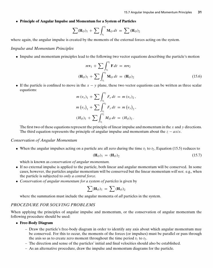
15.5 ANGULAR MOMENTUMThe angular momentum HO of a particle about point O is defined as the “moment”of the particle’s linear momentum about O. It is sometimes referred to as the moment of momentum.
• Scalar Formulation. The magnitude of HO is given by
(HO)z = (d)(mv).
– d is the moment arm (perpendicular distance from O to the line of action of mv).– Direction of HO is defined by the right-hand rule.– Units for (HO)z are kg ·m2/s or slug · f t2/s.
x
y
z
Od
P mv
HO
30 Chap. 15 Kinetics of a Particle: Impulse and Momentum
• Vector Formulation. If the particle P is moving along a space curve and r is a position vector drawn from pointO to the particle P :
HO = r × mv.
Here the vector HO is perpendicular to the plane containing r and mv.
x
y
z
O
Pmv
HO = r × mv
r
15.6 RELATION BETWEEN MOMENT OF A FORCE ANDANGULAR MOMENTUM
• The resultant moment about point O of all the forces acting on a particle is equal to the time rate of change ofthe particle’s angular momentum about point O i.e.,∑
MO = HO
This equation is just Newton’s second law of motion ‘for moments’.
• System of Particles. The sum of the moments about point O of all the external forces acting on a system ofparticles is equal to the time rate of change of the total angular momentum of the system about point O. Thepoint O can be any fixed point in the inertial frame of reference i.e.,∑
(ri × Fi ) =∑(
Hi
)O.
15.7 ANGULAR IMPULSE AND MOMENTUM PRINCIPLES
• Principle of Angular Impulse and Momentum.
(HO)1 +∑∫ t2
t1
MO dt = (HO)2 (15.5)
where the angular impulse is defined by∫ t2
t1
MO dt =∫ t2
t1
(r × F) dt.
Here r is a position vector which extends from any point O to any point on the line of action of the externalforce F acting on the particle.
15.7 Angular Impulse and Momentum Principles 31
• Principle of Angular Impulse and Momentum for a System of Particles∑(HO)1 +
∑∫ t2
t1
MO dt =∑
(HO)2
where again, the angular impulse is created by the moments of the external forces acting on the system.
Impulse and Momentum Principles
• Impulse and momentum principles lead to the following two vector equations describing the particle’s motion
mv1 +∑∫ t2
t1
F dt = mv2
(HO)1 +∑∫ t2
t1
MO dt = (HO)2 (15.6)
• If the particle is confined to move in the x − y plane, these two vector equations can be written as three scalarequations:
m(vx)1 +∑∫ t2
t1
Fx dt = m(vx)2 ,
m(vy)
1 +∑∫ t2
t1
Fy dt = m(vy)
2 ,
(HO)1 +∑∫ t2
t1
MO dt = (HO)2 .
The first two of these equations represent the principle of linear impulse and momentum in the x and y directions.The third equation represents the principle of angular impulse and momentum about the z− axis.
Conservation of Angular Momentum
• When the angular impulses acting on a particle are all zero during the time t1 to t2 , Equation (15.5) reduces to
(HO)1 = (HO)2 (15.7)
which is known as conservation of angular momentum.• If no external impulse is applied to the particle, both linear and angular momentum will be conserved. In some
cases, however, the particles angular momentum will be conserved but the linear momentum will not. e.g., whenthe particle is subjected to only a central force.• Conservation of angular momentum for a system of particles is given by∑
(HO)1 =∑
(HO)2
where the summation must include the angular momenta of all particles in the system.
PROCEDURE FOR SOLVING PROBLEMS
When applying the principles of angular impulse and momentum, or the conservation of angular momentum thefollowing procedure should be used:
• Free-Body Diagram
– Draw the particle’s free-body diagram in order to identify any axis about which angular momentum maybe conserved. For this to occur, the moments of the forces (or impulses) must be parallel or pass throughthe axis so as to create zero moment throughout the time period t1 to t2.
– The direction and sense of the particles’ initial and final velocities should also be established.– As an alternative procedure, draw the impulse and momentum diagrams for the particle.
32 Chap. 15 Kinetics of a Particle: Impulse and Momentum
• Momentum Equations
– Apply the principle of angular impulse and momentum (Equation 15.6) or, if appropriate, the conservationof angular momentum (Equation (15.7).
• See Examples 15.13 to 15.15 in text.
15.8 STEADY FLUID STREAMSProblems involving steady flow can be solved using the following procedure:
• Kinematic Diagram
– If the device is moving, a kinematic diagram may be helpful for determining the entrance and exit velocitiesof the fluid flowing onto the device, since a relative-motion analysis of velocity will be involved.
– The measurement of velocities vA and vB (velocity at which the fluid enters and exits, respectively) mustbe made by an observer fixed in an inertial frame of reference.
– Once the velocity of the fluid flowing onto the device is determined, the mass flow dmdt
is calculated using
dm
dt= ρAvAAA = ρBvBAB = ρAQA = ρBQB.
• Free-Body Diagram
– Draw a free-body diagram of the device which is directing the fluid in order to establish the forces∑
F thatact on it. These external forces will include the support reactions, the weight of the device and the fluidcontained within it, and the static pressure forces of the fluid at the entrance and exit sections of the device.
• Equations of Steady Flow
– Apply the equations of steady flow:∑Fx = dm
dt(vBx − vAx) ,∑
Fy = dm
dt
(vBy − vAy
),∑
MO = dm
dt(dOBvB − dOAvA) ,
using the appropriate components of velocity and force shown on the kinematic and free-body diagrams.
• Examples: See Examples 15-16 to 15-17 in text.
15.9 PROPULSION WITH VARIABLE MASSIn Section 15.8, we considered the case in which a constant amount of mass enters and leaves a closed system. In thissection, we consider two other cases involving mass flow: these are represented by a system which is either gaining orlosing mass.
1. A System that Loses Mass. Consider a device which at an instant in time has a mass m and is moving forwardwith a velocity v.At the same time the system is expelling an amount of massme with a mass flow velocity ve.Thegoverning equation is: ∑
Fs = mdv
dt− vD/e dme
dt. (15.8)
Here,∑
Fs represents the resultant of all the external forces that act on the system in the direction of motion.This does not include the force which causes the device to move forward, since this force (thrust) is internal to
REVIEW QUESTIONS 33
the system; vD/e is the magnitude of the relative velocity of the device as seen by an observer moving with the
particles of the ejected mass; dmedt
represents the rate at which mass is being ejected.
2. A System that Gains Mass. A device such as a scoop or a shovel may gain mass as it moves forward. Consider adevice which at an instant in time has a massm and is moving forward with a velocity v.At this instant, the deviceis collecting a particle stream of mass mi . The flow velocity vi of this injected mass is constant and independentof the velocity v such that v > vi. The governing equation is:
∑Fs = m
dv
dt+ vD/i dmi
dt. (15.9)
Here,∑
Fs represents the resultant of all the external forces that act on the system in the direction of motion.This does not include the retarding force of the injected mass acting on the device since this force is internal tothe system; vD/i is the magnitude of the relative velocity of the device as seen by an observer moving with the
particles of the injected mass; dmidt
represents the rate at which mass is being injected into the device.
Note Problems solved using Equations (15.8) and (15.9) should be accompanied by the necessary correspondingfree-body diagram. With this diagram, one can then determine
∑Fs for the system and isolate the force exerted
on the device by the particle stream.
HELPFUL TIPS AND SUGGESTIONS
• Unlike energy, momentum is a vector and so has both magnitude and direction. Impulse and momentum diagramswill help you keep track of a particle’s initial and final momenta for use in the principle of impulse and momentum.
• Remember that when making the distinction between impulsive and nonimpulsive forces, it is important torealize that this applies only in the very short time interval [t1, t2] during which the impulse acts.
REVIEW QUESTIONS
1. What is the linear momentum of a particle?
2. When is the principle of linear impulse and momentum used to solve problems?
3. When does the principle of linear impulse and momentum become conservation of linear momentum?
4. What is a nonimpulsive force?
5. What is the procedure for determining the final velocities of two smooth particles just after they are subjected todirect central impact if the coefficient of restitution, the mass of each particle, and each particle’s initial velocityjust before impact are known?
6. Define the angular momentum of a particle about a point O .
7. What is meant by conservation of angular momentum?
8. True or false? If a particle’s angular momentum is conserved the particle’s linear momentum must also beconserved.
9. Write down three scalar equations describing impulse and momentum principles for a particle confined to movein the x − y plane.
10. In Equation (15.9) for a system that gains mass,∑
Fs does not include the retarding force of the injected massacting on the device. Why?
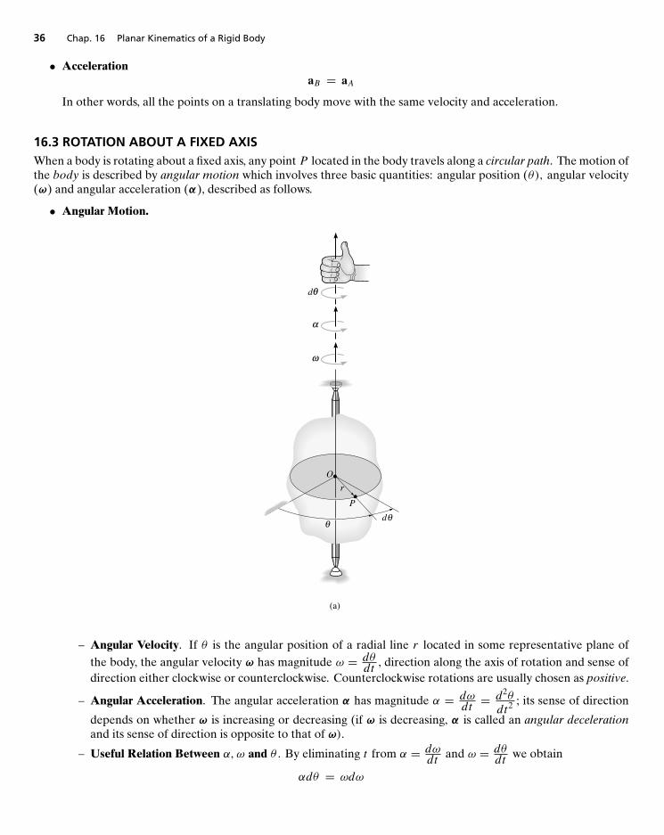
16
Planar Kinematics of a Rigid Body
MAIN GOALS OF THIS CHAPTER:
• To classify the various types of rigid-body planar motion.
• To investigate rigid-body translation and show how to analyze motion about a fixed axis.
• To study planar motion using an absolute motion analysis.
• To show how to find the instantaneous center of zero velocity and determine the velocity of a point on a bodyusing this method.
• To provide a relative motion analysis of velocity and acceleration using a rotating frame of reference.
16.1 PLANAR RIGID-BODY MOTION
• When all the particles of a rigid body move along paths which are equidistant from a fixed plane, the body is saidto undergo planar motion. There are three types of rigid body planar motion:
1. Translation Every line segment in the body remains parallel to its original direction during the motion.Specifically, a body can undergo two types of translation:
i. Rectilinear Translation. All points follow parallel straight-line paths.
ii. Curvilinear Translation. All points follow curved paths that are the same shape and are equidistantfrom one another.
2. Rotation about a Fixed Axis. All of the particles of the body, except those which lie on the axis of rotation,move along circular paths.
3. General Plane Motion. The body undergoes a combination of translation and rotation.
34
16.2 Translation 35
Path of rectilinear translation
(a)
Path of curvilinear translation
(b)
Rotation about a fixed axis
(c)
General plane motion
(d)
16.2 TRANSLATIONLet two points A and B be identified by position vectors ∗rA and ∗rB , respectively, from a fixed x, y reference frame.The kinematics of the translating body can be described as follows:
• PositionrB = rA + rB/A
where rB/A is the relative position vector (measures position of B with respect to A).
y
xO
y'
x'A
B
rB/A
rA
rB
Translatingcoordinate system
Fixedcoordinate system
• Velocity The body is rigid so the magnitude of rB/A is constant. The body is translating so the direction of rB/Ais constant. Hence
vB = vA
36 Chap. 16 Planar Kinematics of a Rigid Body
• AccelerationaB = aA
In other words, all the points on a translating body move with the same velocity and acceleration.
16.3 ROTATION ABOUT A FIXED AXISWhen a body is rotating about a fixed axis, any point P located in the body travels along a circular path. The motion ofthe body is described by angular motion which involves three basic quantities: angular position (θ), angular velocity(ω) and angular acceleration (α), described as follows.
• Angular Motion.
O
P
dθθ
r
(a)
ω
α
θd
– Angular Velocity. If θ is the angular position of a radial line r located in some representative plane ofthe body, the angular velocity ω has magnitude ω = dθ
dt, direction along the axis of rotation and sense of
direction either clockwise or counterclockwise. Counterclockwise rotations are usually chosen as positive.
– Angular Acceleration. The angular acceleration α has magnitude α = dωdt= d2θ
dt2; its sense of direction
depends on whether ω is increasing or decreasing (if ω is decreasing, α is called an angular decelerationand its sense of direction is opposite to that of ω).
– Useful Relation Between α, ω and θ . By eliminating t from α = dωdt
and ω = dθdt
we obtain
αdθ = ωdω
16.3 Rotation about a Fixed Axis 37
– Constant Angular Acceleration. If the angular acceleration of the body is constant, α = αC , we have thefollowing set of formulas which relate the body’s angular velocity, angular position and time.
(� +) ω = ω0 + αCt(� +) θ = θ0 + ω0t + 1
2αCt
2
(� +) ω2 = ω20 + 2αC (θ − θ0)
Here, θ0 and ω0 are the initial values of the body’s angular position and angular velocity, respectively, andwe have chosen counterclockwise rotations as positive.
• Motion of Point P. As the rigid body rotates, point P travels along a circular path of radius r and center at pointO. The motion of point P is described by position, velocity and acceleration.
O
Pφ
rv
rP
ω
– Position. The position of P is defined by the position vector r, which extends from O to P.
– Velocity. The velocity v of P has magnitude v = rω and direction always tangent to the circular path. Thiscan be represented in vector form as
v = ω × rP
where rP is directed from any point on the axis of rotation to point P . As a special case, the position vectorr can be chosen for rP . Here r lies in the plane of motion and again the velocity of point P is
v = ω × r
– Acceleration. The acceleration has two components. The tangential component of acceleration measuresthe rate of change in the magnitude of the velocity and can be determined using at = αr. The normalcomponent of acceleration measures the rate of change in the direction of the velocity and can be determinedfrom an = ω2r. In terms of vectors
at = α × r
an = ω × (ω × r) = −ω2r
a = at + an = α × r − ω2r
38 Chap. 16 Planar Kinematics of a Rigid Body
PROCEDURE FOR SOLVING PROBLEMS
The velocity and acceleration of a point located on a rigid body that is rotating about a fixed axis can be determinedusing the following procedure.
• Angular Motion
– Establish the positive sense of direction along the axis of rotation and show it alongside each kinematicequation as it is applied i.e., either (� +) or (� +).
– If a relationship is known between any two of the four variables α, ω, θ and t , then a third variable can beobtained by using one of the following kinematic equations which relates all three variables
ω = dθ
dt, α = dω
dt, αdθ = ωdω.
– If the body’s angular acceleration is constant, then the following equations can be used:
ω = ω0 + αCtθ = θ0 + ω0t + 1
2αCt
2
ω2 = ω20 + 2αC (θ − θ0)
– Once the solution is obtained, the sense of θ , ω and α is determined from the algebraic signs of theirnumerical quantities.
• Motion of P
– In most cases, the velocity of P and its two components of acceleration can be determined from the scalarequations
v = rω, at = αr, an = ω2r.
– If the geometry of the problem is difficult to visualize, the following vector equations should be used:
v = ω × rP = ω × rat = α × rP = α × r
an = ω × (ω × rP ) = −ω2r
Here, rP is directed from any point on the axis of rotation to point P , whereas r lies in the plane of motionof P. Either of these vectors, along with ω and α should be expressed in terms of its i, j, k components.
16.4 ABSOLUTE MOTION ANALYSIS
PROCEDURE FOR SOLVING PROBLEMS
The velocity and acceleration of a point P undergoing rectilinear motion can be related to the angular velocity andangular acceleration of a line contained within a body using the following procedure.
• Position Coordinate Equation
– Locate point P using a position coordinate s , which is measured from a fixed origin and is directed alongthe straight-line path of motion of point P.
– Measure from a fixed reference line the angular position θ of a line lying in the body.– From the dimensions of the body, relate s to θ , s = f (θ), using geometry and/or trigonometry.
• Time Derivatives
– Take the first derivative of s = f (θ) with respect to time to get a relationship between v (speed) and ω.– Take the second time derivative to get a relationship between a (magnitude of acceleration) and α.– In each case the chain rule of calculus must be used when taking the derivatives of the position coordinate
equation.
16.6 Instantaneous Center of Zero Velocity 39
16.5 RELATIVE MOTION ANALYSIS: VELOCITY
PROCEDURE FOR SOLVING PROBLEMS
• The relative velocity equationvB = vA + vB/A= vA + ω × rB/A
can be applied either by using Cartesian vector analysis, or by writing the x and y scalar component equationsdirectly.
VECTOR ANALYSIS
• Kinematic Diagram
– Establish the directions of the fixed x and y coordinates and draw a kinematic diagram of the body. Indicateon it the velocities vA and vB of points A and B , the angular velocity ω and the relative-position vectorrB/A.
– If the magnitudes of vA , vB or ω are unknown, the sense of direction of these vectors may be assumed.
• Velocity Equation
– To apply vB = vA + ω × rB/A , express the vectors in Cartesian vector form and substitute them into theequation. Evaluate the cross product and then equate the respective i and j components to obtain twoscalar equations.
– If the solution yields a negative answer for an unknown magnitude, it indicates that the sense of directionof the vector is opposite to that shown on the kinetic diagram.
SCALAR ANALYSIS
• Kinematic Diagram
– If the velocity equation is to be applied in scalar form, then the magnitude and direction of the relativevelocity vB/A must be established. Draw a kinetic diagram. Since the body is to be considered pinnedmomentarily at the base point A, the magnitude is vB/A = ωrB/A. The sense of direction of vB/A isestablished from the diagram, such that vB/A acts perpendicular to rB/A in accordance with the rotationalmotion ω of the body.
• Velocity Equation
– Write the equation vB = vA+vB/A, and underneath each of the terms, represent the vectors graphically byshowing their magnitudes and directions. The scalar equations are determined from the x and y componentsof these vectors.
16.6 INSTANTANEOUS CENTER OF ZERO VELOCITY• When using the equation vB = vA+ω × rB/A , the velocity of any point B located on a rigid body can be obtained
in a very direct way if one chooses the base point A to be a point that has a zero velocity at the instant considered.This point is called the instantaneous center of zero velocity (IC), and it lies on the instantaneous axis of zerovelocity which is always perpendicular to the plane of motion. Consequently, since, if A is chosen as the IC,vA = vIC = 0, and
vB = vIC + ω × rB/IC= ω × rB/IC
Hence, point B moves momentarily about the IC in a circular path i.e., the body appears to rotate about theinstantaneous axis. For example, for a wheel which rolls without slipping, the point of contact with the ground isan IC .
40 Chap. 16 Planar Kinematics of a Rigid Body
LOCATION OF THE IC
To locate the IC we use the fact that the velocity of a point on the body is always perpendicular to the relative-position vector extending from the IC to the point (since the point is in circular motion about the IC). There are threepossibilities:
• Given the velocity vA of a point A on the body and the angular velocity ω of the body. In this case, the IC islocated along the line drawn perpendicular to vA at A, such that the distance from A to the IC is rA/IC = vA/ω.Note that the IC lies up and to the right of A since vA must cause a clockwise angular velocity ω about the IC.
ω
ω
vA
rA/IC
A
ICvIC = 0
Location of ICknowing vA and
Centrode
• Given the lines of action of two nonparallel velocities vA and vB . Construct at points A and B line segments thatare perpendicular to vA and vB. Extending these perpendiculars to their point of intersection as shown, locatesthe IC at the instant considered.
Location of ICknowing the lines of action of vA and vB
ω
B
A rA/IC
rB/IC
vB
vAIC
vIC = 0
16.7 Relative-Motion Analysis: Acceleration 41
• Given the magnitude and direction of two parallel velocities vA and vB.Here, the location of the IC is determinedby proportional triangles.
B
A
dIC
rA/IC
rB/IC
vB
vA
(a)
ω
Location of ICknowing vA and vB
ω
rA/IC
B
AvA
vB
IC
d rB/IC
(b)
IMPORTANT NOTES
1. The point chosen as the IC for the body can be used only for an instant of time since the body changes its positionfrom one instant to the next.
2. The IC does not, in general, have zero acceleration and so should not be used for finding accelerations of pointsin a body.
SOLVING PROBLEMS USING THE IC
• First establish the location of the IC using one of the methods described above.
• The body is then imagined as “extended and pinned” at the IC such that, at the instant considered, it rotatesabout this pin with its angular velocity ω.
• The magnitude of velocity for an arbitrary point on the body can be determined using the equation v = rω
where r is the radial line drawn from the IC to each point.
• The line of action of each velocity vector v is perpendicular to its associated radial line r, and the velocity has asense of direction which tends to move the point in a manner consistent with the angular rotation ω of the radialline.
16.7 RELATIVE-MOTION ANALYSIS: ACCELERATION
• An equation relating the accelerations of two points on a rigid body subjected to general plane motion is givenby
aB = aA + α × rB/A − ω2rB/A (16.0)
whereaB = acceleration of base point BaA = acceleration of base point Aα = angular acceleration of the bodyω = angular velocity of the body
rB/A = relative-position vector drawn from A to B
42 Chap. 16 Planar Kinematics of a Rigid Body
• Important Points
1. Before applying Equation (16.0), it will be necessary to determine the angular velocity ω of the body byusing a velocity analysis.
2. If Equation (16.0) is applied to a rigid body which is pin-connected to two other bodies, it should be notedthat points which are coincident at the pin move with the same acceleration, since the path of motion overwhich they travel is the same. Fort example, point B lying on either rod AB or BC in the following crankmechanism.
A
B
C
ωα
Path of B
3. If two bodies contact one another without slipping, and the points in contact move along different paths,the tangential components of acceleration of the points will be the same; however, the normal componentswill not be the same. For example, consider point A on gear B and the coincident point A′ on gear C. Bothmove with the same tangential acceleration (due to rotational motion) but since they both follow differentcurved paths, their normal accelerations are different. Consequently (aA)n �= (aA′)n so that aA �= aA′ .
(a)
BC
A'A
CB
(b)
A A'(aA)n
(aA)taA (aA')t
aA'
(aA')n
16.8 RELATIVE-MOTION ANALYSIS USING ROTATING AXES• Consider an x, y, z coordinate system (with origin at point A) which is assumed to be translating and rotating
with respect to a fixed X, Y,Z coordinate system. We have the following two equations which describe thevelocity and acceleration of a point B .
vB = vA + � × rB/A +(vB/A
)xyz
(16.1)
aB = aA + � × rB/A + �× (� × rB/A) + 2� × (vB/A)xyz + (aB/A)xyz (16.2)
where
vB, aB = velocity/acceleration of B measured from the X, Y,Z referencevA, aA = velocity/acceleration of the origin A of the x, y, z reference, measured from the
X, Y,Z reference(vB/A
)xyz,(aB/A
)xyz= relative velocity/acceleration of “B with respect to A,” as measured by an ob-
server attached to the x, y, z reference�, � = angular velocity/acceleration of the x, y, z reference, measured from the X, Y,Z
reference.rB/A = relative position of “B with respect to A.”
REVIEW QUESTIONS 43
• The term 2�× (vB/A)xyz is called the Coriolis acceleration.
Solving Problems Using Equations (16.1) and (16.2)
• Coordinate Axes
– Choose an appropriate location for the origin and proper orientation of the axes for both the X, Y,Z andmoving x, y, z reference frames.
– Most often solutions are easily obtained if at the instant considered:
1. the origins are coincident2. the corresponding axes are collinear3. the corresponding axes are parallel
– The moving frame should be selected fixed to the body or device along which the relative motion occurs.
• Kinematic Equations
– After defining the origin A of the moving reference and specifying the moving point B write Equations(16.1) to (16.2).
– The Cartesian components of all these vectors may be expressed along either the X, Y,Z axes or the x, y, zaxes. The choice is arbitrary provided a consistent set of unit vectors is used.
– Motion of the moving reference, is expressed by vA, aA , � and �; and the motion of B with respect to themoving reference, is expressed by rB/A,
(vB/A
)xyz
and(aB/A
)xyz.
HELPFUL TIPS AND SUGGESTIONS• When using the relative velocity and acceleration equations
vB = vA + ω × rB/AaB = aA + α × rB/A − ω2rB/A
the choice of point A is essential. It should always be a point whose velocity/acceleration is known or easy tofind.• Recall that the IC of zero velocity does not, in general, have zero acceleration so that although vIC = 0, aIC �= 0.
REVIEW QUESTIONS
1. What are the three types of rigid body planar motion? Give a short description of each.2. Can a point have an angular velocity?3. In absolute motion analysis, we establish a position-coordinate equation s = f (θ) . How do we then obtain the
speed and magnitude of acceleration?
4. If a position-coordinate equation is given by s = f (θ) = sin2 θ where θ (t) and t is time, find the speed dsdt
.
5. For a rigid body in plane motion, is the IC of zero velocity always located either on the body or at a finite distancefrom the body?
6. Once the IC of zero velocity has been found we can write
vB = vIC + ω × rB/IC= ω × rB/IC.
Is it the case that we can also write
aB = α × rB/IC − ω2rB/IC?
7. What does it mean when the term(vB/A
)xyz
is zero?
17
Planar Kinetics of a Rigid Body:
Force and Acceleration
MAIN GOALS OF THIS CHAPTER:• To introduce the methods used to determine the mass moment of inertia of a body.• To develop the planar kinetic equations of motion for a symmetric rigid body.• To discuss applications of these equations to bodies undergoing translation, rotation about a fixed axis, and
general plane motion.
17.1 MOMENT OF INERTIA• The moment of inertia is a measure of the resistance of a body to angular acceleration in the same way that mass
is a measure of the body’s resistance to acceleration.• The body’s moment of inertia about the z− axis is
I =∫m
r2 dm
where the “moment arm” r is the perpendicular distance from the z− axis to the arbitrary element dm. ClearlyI is always positive and has units of kg ·m2 or slug · f t2.
r
dm
z
44
17.2 Planar Kinetic Equations of Motion 45
• If the body consists of material having a variable density, ρ = ρ (x, y, z), we can write dm = ρdV and expressI in terms of volume:
I =∫V
r2ρ dV
If ρ is constant (homogeneous solid), we can write
I = ρ
∫V
r2 dV
• When the elemental volume chosen for integration has infinitesimal dimensions in all three directions, e.g.,dV = dxdydz, the moment of inertia of the body must be determined using “triple integration.” The integrationprocess can, however, be simplified to a single integration provided the chosen elemental volume has a differentialsize or thickness in only one direction. Shell or disk elements are often used for this purpose.
• PARALLEL-AXIS THEOREM. If the moment of inertia IG of a body about an axis passing through the body’smass center G is known, then the moment of inertia I about any other parallel axis is given by
I = IG + md2
wherem = mass of bodyd = perpendicular distance between the parallel axes
• RADIUS OF GYRATION. The radius of gyration k (units of length) is defined by
I = mk2 or k =√I
m
• COMPOSITE BODIES. If a body is constructed of a number of simple shapes such as disks, spheres and rods,the moment of inertia of the body about any axis z can be found by adding algebraically the moments of inertiaof all the composite shapes computed about the z − axis. Here, IG for each of the composite parts is usuallydetermined from tables (see inside back cover of text).
17.2 PLANAR KINETIC EQUATIONS OF MOTION
• Equation of Translational Motion. Measured from an inertial reference frame x, y, z the equation of translationalmotion is given by ∑
F = maG
or, in scalar form:∑Fx = m(aG)x∑Fy = m(aG)y
where∑
F is the sum of all external forces acting on the body and aG is the acceleration of the body’s masscenter.
• Equation of Rotational Motion. The equation of rotational motion takes two forms:
i. When the moments are computed about the body’s mass center G :
�∑
MG = IGα
where∑MG is the sum of the moments of all the external forces and couple moments computed about
the point G, IG is the moment of inertia of the body about an axis passing through G and α is the angularacceleration of the body.
46 Chap. 17 Planar Kinetics of a Rigid Body: Force and Acceleration
ii. When the moments are computed about a point P �= G :
�∑
MP =∑
(Mk)P
or
�∑
MP = IGα + kinetic moments of the components of maG about P
where∑MP is the sum of the moments of all the external forces and couple moments computed about the
point P.
• Free-Body Diagram. A good free-body diagram will help you to identify the terms involved in each of∑
F,∑MG
or∑MP . A kinetic diagram is especially convenient for identifying the moment terms in
Here,∑(Mk)B represents only the moments of the components m(aG)n and m(aG)t about point B (since, in
translation IGα = 0).
PROCEDURE FOR SOLVING PROBLEMS
Kinetic problems involving rigid-body translation can be solved using the following procedure:
• Free-Body Diagram
– Establish the x, y or n, t inertial frame of reference and draw the free-body diagram in order to accountfor all the external forces and couple moments that act on the body.
– The direction and sense of the acceleration of the body’s mass center aG should be established.
– Identify the unknowns in the problem.
– If it is decided that the rotational equation of motion∑MP =
∑(Mk)P is to be used, consider drawing
the kinetic diagram since it graphically accounts for the componentsm(aG)x , m (aG)y orm(aG)n , m(aG)tand is therefore convenient for “visualizing” the terms needed in the moment sum
∑(Mk)P .
17.4 Equations of Motion: Rotation About a Fixed Axis 47
• Equations of Motion
– Apply the three equations of motion in accordance with the established sign convention.
– To simplify the analysis, the moment equation∑MG = 0 can be replaced by the more general equation∑
MP =∑(Mk)P , where point P is usually located at the intersection of the lines of action of as many
unknown forces as possible.
– If the body is in contact with a rough surface and slipping occurs, use the frictional equation F = μkN.
Remember, F always acts on the body so as to oppose the motion of the body relative to the surface itcontacts.
• Kinematics
• Use kinematics if the velocity and position of the body are to be determined.
• For rectilinear translation with variable acceleration use
aG = dvG
dt, aGdsG = vGdvG, vG = dsG
dt
• For rectilinear translation with constant acceleration, use
vG = (vG)0 + aGt, v2G = (vG)
20 + 2aG[sG − (sG)0],
sG = (sG)0 + (vG)0 t +12aGt
2
• For curvilinear translation, use
(aG)n =v2G
ρ= ω2ρ, (aG)t =
dvG
dt, (aG)t dsG = vGdvG,
(aG)t = αρ
17.4 EQUATIONS OF MOTION: ROTATION ABOUT A FIXED AXIS
• Consider a rigid body which is constrained to rotate in the vertical plane about a fixed axis perpendicular to thepage and passing through the pin at O.
O
G
(aG)t
(aG)nrG
M1
M2
F4
F3
F2
F1
αω
48 Chap. 17 Planar Kinetics of a Rigid Body: Force and Acceleration
The three equations of motion are: ∑Fn = m(aG)n = mω2rG∑Ft = m(aG)t = mαrG∑MG = IGα
or for a point O �= G∑MO =
∑(Mk)O = IOα
Note that “IOα” accounts for the “moment” of both m(aG)t and IGα about the point O = (the moment ofm(aG)n is not included since the line of action of this vector passes through O).
PROCEDURE FOR SOLVING PROBLEMS
Kinetic problems involving rotation of a body about a fixed axis can be solved using the following procedure:
• Free-Body Diagram
– Establish the x, y or n, t inertial coordinate system and specify the directions and sense of the accelerations(aG)n and (aG)t and the angular acceleration α of the body. Recall that (aG)t must act in a direction whichis consistent with α whereas (aG)n always acts towards the axis of rotation which is point O.
– Draw the free-body diagram in order to account for all the external forces and couple moments that act onthe body.
– Compute the moment of inertia IG or IO.
– Identify the unknowns in the problem.
– If it is decided that the rotational equation of motion∑MP =
∑(Mk)P is to be used, i.e., P is a point other
than G or O , consider drawing the kinetic diagram in order to help “visualize” the “moments” developedby the components m(aG)n , m(aG)t and IGα when writing the terms for the moment sum
∑(Mk)P .
• Equations of Motion
– Apply the three equations of motion in accordance with the established sign convention.
– If moments are summed about the body’s mass center G, then∑MG = IGα since m(aG)n and m(aG)t
create no moment about G.
– If moments are summed about the pin support O on the axis of rotation, then m(aG)n creates no momentabout O and it can be shown that
∑MO = IOα .
• Kinematics
– Use kinematics if a complete solution cannot be obtained strictly from the equations of motion.
– If angular acceleration is variable, use
α = dω
dt, αdθ = ωdθ, ω = dθ
dt
– If angular acceleration is constant, use
ω = ω0 + αCt, ω2 = ω20 + 2αC[θ − θ0],
θ = θ0 + ω0t + 12αCt
2
17.5 Equations of Motion: General Plane Motion 49
17.5 EQUATIONS OF MOTION: GENERAL PLANE MOTION• If an x, y inertial coordinate system is used, the three equations of motion are∑
Fx = m(aG)x∑Fy = m(aG)y∑MG = IGα
or summing moments about P �= G :∑MP =
∑(Mk)P
Here,∑(Mk)P represents the moment sum of IGα and maG (or its components) about P as determined by the
data on the kinetic diagram.• Frictional Rolling Problems. In addition to the three equations of motion for general plane motion, frictional
rolling problems (involving e.g., wheels, disks, cylinders, or balls) often require an extra equation due to thepresence of the ‘extra unknown’ representing the frictional force. There are two cases:
– No slipping. In this case we have the ‘extra equation’
aG = rα.
Note that when the solution is obtained, the assumption of no slipping must be checked (i.e., verify thatF ≤ μsN ) otherwise it is necessary to rework the problem under the assumption of slipping.
– Slipping. Here, α and aG are independent of each other so instead we relate the magnitude of the frictionalforce F to the magnitude of the normal force N using the coefficient of kinetic friction μk and obtain the‘extra equation’
F = μkN
PROCEDURE FOR SOLVING PROBLEMS
Kinetic problems involving general plane motion of a rigid-body can be solved using the following procedure:
• Free-Body Diagram
– Establish the x, y inertial frame of reference and draw the free-body diagram in order to account for allthe external forces and couple moments that act on the body.
– The direction and sense of the acceleration of the body’s mass center aG and the angular acceleration α ofthe body should be established.
– Compute the moment of inertia IG– Identify the unknowns in the problem.– If it is decided that the rotational equation of motion
∑MP =
∑(Mk)P is to be used, consider drawing
the kinetic diagram in order to help “visualize” the “moments” developed by the components m(aG)x ,m(aG)y and IGα when writing the terms for the moment sum
∑(Mk)P .
• Equations of Motion
– Apply the three equations of motion in accordance with the established sign convention.– When friction is present, there is the possibility for motion with no slipping or tipping. Each possibility for
motion should be considered.
• Kinematics
– Use kinematics if a complete solution cannot be obtained strictly from the equations of motion.– If the body’s motion is constrained due to its supports, additional equations may be obtained by using
aB= aA+aB/A, which related the accelerations of any two points A and B on the body.– When a wheel, disk, cylinder, or ball rolls without slipping then aG = rα.
50 Chap. 17 Planar Kinetics of a Rigid Body: Force and Acceleration
HELPFUL TIPS AND SUGGESTIONS• Remember always to draw a free-body diagram to account for all the external forces and couple moments that
act on the body. Also, a good kinetic diagram will help you to visualize the “moments” when writing the termsfor the moment sum
∑(Mk)P .
• Before attempting any of the problems, study Examples 17-5 to 17-17 in the text. Re-work a few of theseyourself knowing you have the full solution available. This is an excellent way to reinforce ideas and understandthe relevant material.
REVIEW QUESTIONS
1. What is meant by a moment of inertia?2. What is meant by a homogeneous solid?3. What’s the easiest way to calculate moments of inertia for common homogeneous solids?4. In the equation of rotational motion, what is meant by the term
∑(Mk)P ?
5. True or False? In translational problems, the moments of external forces and couples taken about any point addto zero.
6. Is it true that in problems involving rotation about a fixed axis, we can write∑MP = IP α for any point P ?
7. Is it true that∑MIC = IICα where IC represents the instantaneous center of zero velocity?
8. Consider the homogeneous disk with massm subjected to a known horizontal force P.Draw a free-body diagramand write down three equations of motion for the disk. Next, assuming the disk rolls without slipping, write downanother equation for the disk. Is there enough information to solve the problem of finding e.g., the accelerationof G?
Pr
G
18
Planar Kinetics of a Rigid Body:
Work and Energy
MAIN GOALS OF THIS CHAPTER:
• To develop formulations for the kinetic energy of a body and define the various ways a force and couple do work.
• To apply the principle of work and energy to solve rigid-body planar kinetic problems that involve force, velocityand displacement.
• To show how the conservation of energy can be used to solve rigid-body planar kinetic problems.
18.1 KINETIC ENERGY
• Translation. When a rigid body of mass m is subjected to either rectilinear or curvilinear translation, the kineticenergy of the body is
T = 12mv2
G
where vG is the magnitude of the translational velocity vG at the instant considered. Clearly, in this case, T ismade up solely from translational kinetic energy.
• Rotation about a Fixed Axis. When a rigid body is rotating about a fixed axis passing through point O, thekinetic energy of the body is given by
T = 12mv2
G +12IGω
2
= 12IOω
2
Here ω is the angular velocity of the body and IO is the body’s moment of inertia computed about the z− axispassing through point O. In this case, it is clear that T is made up from both translational kinetic energy 1
2mv2G
and rotational kinetic energy about the body’s mass center, 12IGω
2. However, since the motion is one of rotationabout O, vG takes a special form (vG = rGω) which, using the parallel axis theorem, leads to the more compactexpression T = 1
2IOω2.
51
52 Chap. 18 Planar Kinetics of a Rigid Body: Work and Energy
• General Plane Motion. When a rigid body is subjected to general plane motion, its kinetic energy is defined by
T = 12mv2
G +12IGω
2
In this case, T is the scalar sum of the body’s translational kinetic energy 12mv
2G and rotational kinetic energy
about its mass center, 12IGω
2. Note that there is now no special form for vG (unlike rotational case) so we cannotcollapse the expression for T using the parallel axis theorem.• System of Connected Rigid Bodies. Since energy is a scalar quantity, the total kinetic energy for a system of
connected rigid bodies is the sum of the kinetic energies of all its moving parts.
18.2 THE WORK OF A FORCE• Work of a Variable Force. If an external force F acts on a rigid body, the work done by the force when it moves
along the path s is defined as
UF =∫S
F cos θ ds
where θ is the angle between the tails of the force vector and the differential displacement.• Work of a Constant Force. If an external force Fc acts on a rigid body and maintains a constant magnitude Fc
and constant direction θ, the work becomes
UFc = (Fc cos θ) s
Here, Fc cos θ represents the magnitude of the component of force in the direction of displacement.• Work of a Weight. The weight of a body does work only when the body’s mass center G undergoes a vertical
displacement �y. If this displacement is upward, the work is negative
UW = −W�yLikewise, if the displacement is downward (−�y), the work is positive
UW = W�y• Work of a Spring Force. If a linearly elastic spring is attached to a body, the spring force F = ks acting on the
body does work when the spring either stretches or compresses from s1 to a further position s2 . In both cases,the work is negative (since body’s displacement is in opposite direction of force):
Us = −12k(s2
2 − s21
), |s2| > |s1|
• Forces that do no Work. There are some external forces that do no work when the body is displaced. Theseforces can act either at fixed points on the body or they can have a direction perpendicular to their displacement.e.g., reactions at a pin support about which a body rotates or the weight of a body when the center of gravity ofthe body moves in a horizontal plane.
18.3 THE WORK OF A COUPLE• When a body subjected to a couple undergoes general plane motion, the two couple forces do work only when
the body undergoes a rotation. When the body rotates in the plane through a finite angle θ (radians) from θ1 toθ2,the work of the couple is then
UM =∫ θ2
θ1
M dθ
• If the couple moment M has a constant magnitude, then
UM = M (θ2 − θ1)
Here, the work is positive provided M and (θ2 − θ1) are in the same direction.
18.5 Conservation of Energy 53
18.4 PRINCIPLE OF WORK AND ENERGYThe principle of work and energy for a rigid body is
T1 +∑
U1−2 = T2
PROCEDURE FOR SOLVING PROBLEMS
The principle of work and energy is used to solve kinetic problems that involve velocity, force and displacement, sincethese terms are involved in the formulation. We use the following procedure:
• Work (Free-Body Diagram)
– Draw a free-body diagram of the body when it is located at an intermediate point along the path in orderto account for all the forces and couple moments which do work on the body as it moves along the path.
– A force does work when it moves through a displacement in the direction of the force.– Forces that are functions of displacement must be integrated to obtain the work.– Since algebraic addition of the work terms is required, it is important that the proper sign of each term
be specified. Specifically, work is positive when the force (couple moment) is in the same direction as itsdisplacement (rotation); otherwise it is negative.
• Principle of Work and Energy
– Apply the principle of work and energy, T1 +∑U1−2 = T2. Since this is a scalar equation, it can be used
to solve for only one unknown when it is applied to a single rigid body.
18.5 CONSERVATION OF ENERGY• When a force system acting on a rigid body consists only of conservative forces, the conservation of energy theorem(T1 + V1 = T2 + V2)may be used to solve a problem which would otherwise be solved using the principle of workand energy. This theorem is often easier to apply since the work of a conservative force is independent of thepath and depends on only the initial and final positions of the body.
PROCEDURE FOR SOLVING PROBLEMS
The conservation of energy equation is used to solve kinetic problems that involve velocity, displacement and conser-vative force systems. We use the following procedure:
• Potential Energy
– Draw two diagrams showing the body located at its initial and final positions along the path.– If the center of gravity G is subjected to a vertical displacement, establish a fixed horizontal datum from
which to measure the body’s gravitational potential energy Vg.– Data pertaining to the elevation yG of the body’s center of gravity from the datum and the extension or
compression of any connecting springs can be determined from the problem geometry and listed on thetwo diagrams.
– Recall that the potential energy V = Vg + Ve. Here, Vg = WyG, which can be positive or negative andVe = 1
2ks2, which is always positive..
• Kinetic Energy
– The kinetic energy of the body consists of two parts, namely translational kinetic energy, T = 12mv
2g and
rotational kinetic energy, T = 12IGω
2.
– Kinetic diagrams for velocity may be useful for determining vG and ω or for establishing a relationshipbetween these quantities.
54 Chap. 18 Planar Kinetics of a Rigid Body: Work and Energy
• Conservation of Energy
– Apply the conservation of energy equation T1 + V1 = T2 + V2.
HELPFUL TIPS AND SUGGESTIONS• Remember that unlike force, acceleration or displacement, energy is a scalar.• A brief review of Sections 16.5 to 16.7 may prove helpful in solving problems involving energy since computations
for kinetic energy require a kinematic analysis of velocity.• Only problems involving conservative forces (weights and springs) may be solved using conservation of energy .
Friction or other drag-resistant forces, which depend on velocity or acceleration are nonconservative (a portionof the work done by such forces is transformed into thermal energy which dissipates into the surroundings andmay not be recovered). When such forces enter into the problem, use the principle of work and energy.
REVIEW QUESTIONS
(Note that much of the material in this Chapter requires a review of Chapter 14)
1. What’s the main difference in work and energy methods when they are applied to problems involving rigid bodiesas opposed to when they are applied to problems involving particles (Chapter 14)?
2. How would you calculate the work done by a variable external force F acting on a rigid body as it moves alongthe path s?
3. How would you calculate the work done by a couple moment M with constant magnitude which causes a rigidbody to rotate in the plane through a finite angle θ from θ1 to θ2?
4. When is the principle of work and energy used to solve kinetic problems?5. What is a conservative force? Give some examples of conservative forces.6. Explain why the weight of a body is a conservative force.7. Give an example of a nonconservative force and explain why the force is nonconservative.8. What is potential energy? Give some examples.9. How can you prove that a force F is conservative?
10. When is the conservation of energy equation used to solve problems in kinetics?
19
Planar Kinetics of a Rigid Body:
Impulse and Momentum
MAIN GOALS OF THIS CHAPTER:• To develop formulations for the linear and angular momentum of a body.• To apply the principles of linear and angular impulse and momentum to solve rigid-body planar kinetic problems
that involve force, velocity, and time.• To discuss application of the conservation of momentum• To analyze the mechanics of eccentric impact.
19.1 LINEAR AND ANGULAR MOMENTUM• Linear Momentum. The linear momentum of a rigid body is the vector
L = mvG
with magnitude mvG (units of kg ·m/s or slug · f t/s) and a direction defined by vG .• Angular Momentum. The angular momentum of a rigid body is the vector
HG = IGω
with magnitude IGω (units of kg ·m2/s or slug ·f t2/s) and a direction defined by ω, which is always perpendicularto the plane of motion.
Note The angular momentum of the body can also be computed about a point P �= G. In this case:
HP = IGω + moment of the linear momentum mvG about P
There are three types of motion to consider:
• Translation. When a rigid body is subjected to translation (ω = 0), we obtain
L = mvGHG = 0
or for some point A �= G
HA = (d) (mvG) �
55
56 Chap. 19 Planar Kinetics of a Rigid Body: Impulse and Momentum
d
G
L = mvG
vG = vA
Translation
• Rotation About a Fixed Axis. When a rigid body is rotating about a fixed axis passing through point O, we have
L = mvGHG = IGω or HO = IOω
G
L = mvGω
HG = IGω
O
Rotation about a fixed axis
rG
• General Plane Motion. When a rigid body is subjected to translation (ω = 0), we obtain
L = mvGHG = IGω
or for some point A �= G+� HA = IGω + (d) (mvG)
HG = IGω
L = mvG
G
A
d
General plane motion
19.2 Principle of Impulse and Momentum 57
19.2 PRINCIPLE OF IMPULSE AND MOMENTUM• Principle of Linear Impulse and Momentum. The sum of all the impulses created by an external force system
which acts on the body during the time interval t1 to t2 is equal to the change in the linear momentum of thebody during the time interval. That is:∑∫ t2
t1
F dt = m(vG)2 − m(vG)1• Principle of Angular Impulse and Momentum. The sum of the angular impulses acting on the body during the
time interval t1 to t2 is equal to the change in the body’s angular momentum during this time interval. That is:
– Body in General Plane Motion∑∫ t2
t1MG dt = IGω2 − IGω1
– Body Rotating About a Fixed Axis Passing Through O∑∫ t2
t1MO dt = IOω2 − IOω1
• Motion in the x − y Plane. In the case of planar motion, we have the following three scalar equations:
m(v + Gx)1 +∑∫ t2
t1Fx dt = m(vGx)2
m(vGy
)1 +
∑∫ t2
t1Fy dt = m
(vGy
)2 (19.0)
IGω1 +∑∫ t2
t1MG dt = IGω2
The first two of these equations represent the principle of linear impulse and momentum in the x − y plane andthe third equation represents the principle of angular impulse and momentum about the z− axis which passesthrough the body’s mass center G• Systems of Connected Bodies. Equations (19.0) may also be applied to an entire system of connected bodies
rather than to each body separately. Doing this eliminates the need to include reactive impulses which occur atthe connections since they are internal to the system.
PROCEDURE FOR SOLVING PROBLEMS
Impulse and momentum principles are used to solve kinetic problems that involve velocity, force and time, since theseterms are involved in the formulation. We use the following procedure:
• Free-Body Diagram
– Establish the x , y ,z inertial frame of reference and draw the free-body diagram in order to account for allthe external forces and couple moments that produce impulses on the body.
– The direction and sense of the initial and final velocity of the body’s mass center vG and the body’s an-gular velocity ω should be established. If any of these motions is unknown, assume that the sense of itscomponents is in the direction of the positive inertial coordinates.
– Compute the moment of inertia IG or IO.– As an alternative procedure, draw the impulse and momentum diagrams for the body or system of bodies.
Each of these diagrams represents an outlined shape of the body which graphically accounts for the datarequired for each of the three terms in Equations (19.0). These diagrams are particularly helpful in visual-izing the “moment” terms used in the principle of angular impulse and momentum, if application is abouta point other than the body’s mass center G or a fixed point O.
58 Chap. 19 Planar Kinetics of a Rigid Body: Impulse and Momentum
• Principle of Impulse and Momentum
– Apply the three scalar equations of impulse and momentum.– All the forces acting on the body’s free-body diagram will create an impulse; however, some of these forces
will do no work.– Forces that are functions of time must be integrated to obtain the impulse.– The principle of angular impulse and momentum is often used to eliminate unknown impulsive forces that
are parallel or pass through a common axis, since the moment of these forces is zero about this axis.
• Kinematics
– If more than three equations are needed for a complete solution, it may be possible to relate the velocityof the body’s mass center to the body’s angular velocity using kinematics.
• See Examples 19-3 to 19-5 in text
19.3 CONSERVATION OF MOMENTUM• Conservation of Linear Momentum. If the sum of all the linear impulses acting on a system of rigid bodies is
zero, the linear momentum of the system is constant or conserved i.e.,(∑system linear momentum
)1=(∑
system linear momentum)
2
Note It may be possible to apply conservation of linear momentum without inducing appreciable errors evenwhen the linear impulses are small or nonimpulsive (small forces acting over very short periods of time e.g.,weight of a body).• Conservation of Angular Momentum. The angular momentum of a system of connected rigid bodies is conserved
about the system’s center of mass G, or a fixed point O, when the sum of all the angular impulses created bythe external forces acting on the system is zero or appreciably small (nonimpulsive) when computed about thesepoints i.e., (∑
system angular momentum)O1=(∑
system angular momentum)O2
NOTE The angular momentum can be conserved while the linear momentum is not. Such cases occur wheneverthe external forces creating the linear impulse pass through either the center of mass of the body or a fixed axisof rotation.
PROCEDURE FOR SOLVING PROBLEMS
Provided the initial linear or angular momentum is known, the conservation of linear or angular momentum is usedto determine the respective final linear or angular velocity of the body just after the time period considered. We usethe following procedure:
• Free-Body Diagram
– Establish the x, y inertial frame of reference and draw the free-body diagram for the body or system ofbodies during the time of impact. From this diagram, classify each of the applied forces as being wither“impulsive” or “nonimpulsive.”
– By inspection of the free-body diagram, the conservation of linear momentum applies in a given directionwhen no external impulsive forces act on the body or system in that direction; whereas the conservation ofangular momentum applies about a fixed point O or at the mass center G of a body or system of bodieswhen all the external forces acting on the body or system create zero moment (or zero angular impulse)about O or G.
– As an alternative procedure, draw the impulse and momentum diagrams for the body or system of bodies.These diagrams are particularly helpful in visualizing the “moment” terms used in the conservation ofangular momentum equation if application is about a point other than the body’s mass center G.
HELPFUL TIPS AND SUGGESTIONS 59
• Conservation of Momentum
– Apply the conservation of linear or angular momentum in the appropriate directions.
19.4 ECCENTRIC IMPACT
• Eccentric Impact occurs when the line connecting the mass centers of the two bodies does not coincide with theline of impact. For example:
AB
C
O
Lineof impact
Plane of impact
PROCEDURE FOR SOLVING PROBLEMS
• In general, a problem involving the impact of two bodies requires determining the two unknowns (vA)2 and (vB)2 ,assuming (vA)1 and (vB)1 are known (or can be determined using kinematics, energy methods, the equations ofmotion etc.). To solve this problem, two equations must be written:
– The first equation generally involves application of the conservation of angular momentum to the two bodies.In the case of both bodies A and B , we can state that angular momentum is conserved about point O sincethe impulses at C are internal to the system and the impulses at O create zero moment (or zero angularimpulse) about point O.
– The second equation is obtained using the definition of the coefficient of restitution e :
e = (vB)2 − (vA)2(vA)1 − (vB)1
.
HELPFUL TIPS AND SUGGESTIONS
• Momentum is a vector and so has magnitude and direction.
• Before applying the equations of impulse and momentum, draw a free-body diagram in order to identify all theforces which cause linear and angular impulses on the body
• If nonimpulsive forces or no impulsive forces act on the body in a particular direction, or if the motions of severalbodies are involved in the problem, then consider applying the conservation of linear or angular momentumfor the solution. Investigation of the free-body diagram (or the impulse diagram) will aid in determining thedirections for which the impulsive forces are zero, or axes about which the impulsive forces cause zero angularmomentum.
60 Chap. 19 Planar Kinetics of a Rigid Body: Impulse and Momentum
REVIEW QUESTIONS
1. What is meant by linear momentum?2. What is meant by angular momentum?3. True or False? When a body is in translation, the body’s linear and angular momentum is given by
L = mvGHA = 0
where A is any point on or off the body.4. True or False? When a body is in general plane motion, the body’s linear and angular momentum is given by
L = mvGHA = IAω
where A is any point on or off the body.5. In the case of a system of connected rigid bodies, what is the advantage in applying equations of impulse and
momentum to the entire system rather than to each body separately?6. Explain what is meant by a nonimpulsive force.7. Consider a swimmer who executes a somersault after jumping off a diving board. The swimmer first tucks his
arms and legs in close to his chest, then straightens out just before entering the water. Explain why using conceptsfrom impulse and momentum.
8. If angular momentum is conserved is it the case that linear momentum is also always conserved?
20
Three-Dimensional Kinematics
of a Rigid Body
MAIN GOALS OF THIS CHAPTER:
• To analyze the kinematics of a body subjected to rotation about a fixed axis and general plane motion.
• To provide a relative-motion analysis of a rigid body using translating and rotating axes.
20.1 ROTATION ABOUT A FIXED POINT
• Rotation About a Fixed Point. In three-dimensions, when a body rotates about a fixed point, the path of motionfor a particle P lies on the surface of a sphere having a radius r (distance from the fixed point to P) and centeredat the fixed point.
• Euler’s Theorem. Two “component” rotations about different axes passing through a point are equivalent to asingle resultant rotation about an axis passing through that point.
• Finite Rotations. If the component rotations used in Euler’s theorem are finite (as opposed to infinitesimal) it isimportant that the order in which they are applied be maintained. This is because finite rotations do not obeythe commutative law of addition (e.g., for the two finite rotations θ1 and θ2 , θ1 + θ2 �= θ2 + θ1) and so cannot beclassified as vector quantities.
• Infinitesimal Rotations. Rotations which are infinitesimally small (e.g., dθ)may be classified as vectors since theycan be added vectorially in any manner. For this reason, when defining the angular motions of a body subjectedto three-dimensional motion, only rotations which are infinitesimally small will be considered.
• Angular Velocity. If the body is subjected to an angular rotation dθ about a fixed point, the angular velocity ofthe body is defined by
ω = θ
The line specifying the direction of ω, which is collinear with dθ is referred to as the instantaneous axis of rotation.In general, this axis changes direction during each instant of time. Since dθ is a vector, so too is ω, and it followsfrom vector addition that if the body is subjected to two component angular motions, ω1= θ1 and ω2= θ2, theresultant angular velocity is ω = ω1 + ω2.
61
62 Chap. 20 Three-Dimensional Kinematics of a Rigid Body
1
θd
ω
Instantaneous axisof rotation
ω
2ω
O
• Angular Acceleration. The body’s angular acceleration is given by
α = ω
For motion about a fixed point, α must account for a change in both the magnitude and direction of ω, so that,in general, α is not directed along the instantaneous axis of rotation.
P
rω
O
Instantaneous axisof rotation
α
• Velocity. Once ω is specified, the velocity of any point P on a body rotating about a fixed point is given by
v = ω × r
where r defines the position of P measured from the fixed point O .• Acceleration. If ω and α are known at a given instant, the acceleration of any point P on a body rotating about
a fixed point is given bya = α × r + ω × (ω × r).
Note that the form of this equation is the same as that developed in Chapter 16 for planar kinematics.
20.2 THE TIME DERIVATIVE OF A VECTOR MEASURED FROMEITHER A FIXED OR TRANSLATING-ROTATING SYSTEM•
A= (A)xyz+ � × A (20.0)
where(A)xyz=Ax i + Ayj + Azk
That is, the time derivative of any vector A as observed from the fixed X, Y,Z frame of reference is equal tothe time rate of change of A as observed from the x, y, z translating-rotating frame of reference,
(A)xyz=
Ax i+ Ayj+ Azk, plus �× A, the change of A caused by the rotation of the xyz frame.
20.4 Relative-Motion Analysis Using Translating and Rotating Axes 63
Y
X
Z
x
y
z
ki
j
ΩA
• – Equation (20.0) should always be used whenever � produces a change in the direction of A as seen fromthe X, Y,Z reference.
– Clearly, if � = 0, then A = (A)xyz, and so the time rate of change of A as observed from both coordinate
systems will be the same.
20.3 GENERAL MOTION• Consider a rigid body subjected to general motion in three dimensions for which the angular velocity is ω and
the angular acceleration is α. If point A has a known motion of vA and aA , the motion of any other point B isgiven by
vB = vA + ω × rB/AaB = aA + α × rB/A + ω × (ω × rB/A)
These two equations are identical to those describing general plane motion of a rigid body (Chapter 16). However,difficulty in application arises for three-dimensional motion, because α measures the change in both the directionand magnitude of ω (in the plane, α measures only a change in the magnitude of ω).
20.4 RELATIVE-MOTION ANALYSIS USING TRANSLATING ANDROTATING AXES• The most general way to analyze the three-dimensional motion of a rigid body requires the use of x, y, z axes
that both translate and rotate relative to a second frame X, Y,Z. The main equations are identical in form tothose used in Section 16.8 for analyzing relative plane motion. We review them here briefly:
vB = vA + � × rB/A +(vB/A
)xyz
(20.1)
aB = aA + � × rB/A + �× (� × rB/A) + 2� × (vB/A)xyz + (aB/A)xyz (20.2)
where
vB, aB = velocity/acceleration of B, measured from the X, Y,Z referencevA, aA = velocity/acceleration of the origin A of the x, y, z reference, measured from the
X, Y,Z reference(vB/A
)xyz,(aB/A
)xyz= relative velocity/acceleration of “B with respect to A”, as measured by an ob-
server attached to the x, y, z reference�, � = angular velocity/acceleration of the x, y, z reference, measured from the X, Y,Z
reference.rB/A = relative position of “B with respect to A” .
64 Chap. 20 Three-Dimensional Kinematics of a Rigid Body
The main difference in using these equations for three-dimensional motion is that � depends on the change inboth the magnitude and direction of � (in plane motion, � and � have a constant direction which is alwaysperpendicular to the plane of motion so application of these equations is simplified). Consequently, for three-dimensional motion, � must be computed using Equation (20.0) i.e., � = (�)
xyz+�× A.
PROCEDURE FOR SOLVING PROBLEMS
Three-dimensional motion of particles or rigid bodies can be analyzed with Equations (20.1) and (20.2) using thefollowing procedure:
• Coordinate Axes
– Select the location and orientation of the X, Y,Z and x, y, z coordinate axes. Most often solutions areeasily obtained if at the instant considered
1. the origins are coincident2. the axes are collinear3. the axes are parallel
– If several components of angular velocity are involved in a problem, the calculations will be reduced if thex, y, z axes are selected such that only one component of angular velocity is observed in this frame
(�xyz
)and the frame rotates with � defined by the other components of angular velocity.
• Kinematic Equations
– After the origin of the moving reference, A, is defined and the moving point B is specified, Equations (20.1)and (20.2) should be written in symbolic form as
vB = vA + � × rB/A +(vB/A
)xyz
aB = aA + � × rB/A + �× (� × rB/A) + 2� × (vB/A)xyz + (aB/A)xyz
– If rA and � appear to change direction when observed from the fixed X, Y,Z reference, use a set of primedreference axes x ′, y ′, z′ having �′ = � and Equation (20.0) to determine � and the motion vA and aA ofthe origin of the moving x, y, z axes.
– If(rB/A
)xyz
and �xyz appear to change direction when observed from the x, y, z reference, use a set of
primed reference axes x ′, y ′, z′ having �′ = �xyz and Equation (20.0) to determine �xyz and the relativemotion
(vB/A
)xyz
and(aB/A
)xyz
.
– After the final forms of �, vA, aA, �xyz,(vB/A
)xyz
and(aB/A
)xyz
are obtained, numerical problem data maybe substituted and the kinematic terms evaluated. The components of all these vectors may be selectedeither along the X, Y,Z axes or along x, y, z. The choice is arbitrary, provided a consistent set of unitvectors is used.
• See Examples 20-4 and 20-5 in text
HELPFUL TIPS AND SUGGESTIONS
• The vector form of the kinematic equations for vB and aB (see Equations (20.1) and (20.2) above and Section16.8 in text) are identical in both plane and three-dimensional kinematics. This, in itself, is sufficient reason tobecome comfortable with vector calculus and vector algebra when studying problems in mechanics.• Examples and worked problems are the key - especially in three-dimensional problems where it is much more
difficult to visualize the ‘motion.’ Work through Examples 20-1 to 20-5 in the text yourself before attempting theproblems. You will gain a much better understanding of the equations and how to apply them.
REVIEW QUESTIONS 65
REVIEW QUESTIONS
1. True or False? If the component rotations used in Euler’s theorem are finite, the order in which they are appliedis not important.
2. What is meant by an “infinitesimal rotation”?3. What’s the significance of the angular velocity vector � in Equation (20.0).4. Can you use Equation (20.0) (and your answer to Question 3) to show that it is meaningless to talk about the
angular velocity of a point ?5. Can you prove that the angular velocity vector � satisfying Equation (20.0) is unique? Hint: assume there are
two such vectors and show that they necessarily coincide.6. What’s the only difference when using the equations
vB = vA + ω × rB/AaB = aA + α × rB/A + ω × (ω × rB/A)
in three-dimensional kinematics as opposed to plane kinematics?
21
Three-Dimensional Kinetics
of a Rigid Body
MAIN GOALS OF THIS CHAPTER:
• To introduce the methods for finding the moments of inertia and products of inertia of a body about various axes.
• To show how to apply the principles of work and energy and linear and angular momentum to a rigid body havingthree-dimensional motion.
• To develop and apply the equations of motion in three dimensions
• To study the motion of a gyroscope and torque-free motion.
21.1 MOMENTS AND PRODUCTS OF INERTIA
When studying the planar kinetics of a body, it was necessary to introduce the moment of inertia IG , which wascomputed about an axis perpendicular to the plane of motion and passing through the body’s mass center G. For thekinetic analysis of three-dimensional motion it will sometimes be necessary to calculate six inertial quantities. Theseare called moments and products of inertia and describe, in a particular way, the distribution of mass for a body relativeto a given coordinate system that has a specified orientation and point of origin.
• Moment of Inertia.
Ixx =∫m
r2x dm =
∫m
(y2 + z2) dm
Iyy =∫m
r2y dm =
∫m
(x2 + z2) dm
Izz =∫m
r2z dm =
∫m
(y2 + x2) dm
Clearly, the moment of inertia is always positive.
66
21.1 Moments and Products of Inertia 67
z
dm
rz
rx
ry
z
xy
x
yO
• Product of Inertia. The product of inertia is defined with respect to a set of two orthogonal planes as follows:
Ixy = Iyx =∫m
xy dm
Iyz = Izy =∫m
yz dm
Ixz = Izx =∫m
xz dm
The product of inertia may be positive, negative or zero. Also, if either one or both of the correspondingorthogonal planes are planes of symmetry for the mass, the product of inertia with respect to these planes willbe zero.
• Parallel-Axis Theorem. If the body’s mass center G has coordinates xG, yG, zG then the parallel-axis equationsused to calculate the moments of inertia about the x, y, z axes are
Ixx = (Ix′x′)G + m(y2G + z2
G
)Iyy =
(Iy′y′
)G+ m (x2
G + z2G
)Izz = (Iz′z′)G + m
(x2G + y2
G
)
z
x
y
y'
z'
x'
G
zG
xG
yG
• Parallel-Plane Theorem. The parallel-plane theorem is used to transfer the products of inertia of the body froma set of three orthogonal planes passing through the body’s mass center to a corresponding set of three parallel
68 Chap. 21 Three-Dimensional Kinetics of a Rigid Body
planes passing through some other point O If xG, yG, zG are the perpendicular distances between the planes,the parallel-plane equations are:
Ixy =(Ix′y′
)G+ mxGyG
Iyz =(Iy′z′
)G+ myGzG
Izx = (Iz′x′)G + mzGxG• Inertia Tensor. The inertial properties of a body are completely characterized by nine terms, six of which are
independent. We organize these terms in an array called the inertial tensor:⎛⎝ Ixx −Ixy −Ixz−Iyx Iyy −Iyz−Izx −Izy Izz
⎞⎠
The inertial tensor has a unique set of values for a body when it is computed for each location of the origin Oand orientation of the coordinate axes.
• Principal Moments and Axes of Inertia. In general, for point O, we can specify a unique axes inclination forwhich the products of inertia for the body are zero when computed with respect to these axes. When this is done,the inertia tensor is diagonalized i.e., it can be written as⎛
⎝ Ix 0 0
0 Iy 0
0 0 Iz
⎞⎠
where Ix = Ixx, Iy = Iyy and Iz = Izz are termed principal moments of inertia for the body which are computedfrom the principal axes of inertia. Of the three principal moments of inertia, one will be a maximum and anothera minimum of the body’s moment of inertia.
• Moment of Inertia About an Arbitrary Axis. Suppose we have calculated all 9 components of the inertia tensorfor the x, y, z axes having an origin at O and we now wish to determine the moment of inertia of the body aboutthe Oa axis, whose direction is defined by the unit vector ua .
z
x
yO
b = r sin
θ
θ
a
ua
r
dm
We have
IOa = Ixxu2x + Iyyu2
y + Izzu2z − 2Ixyuxuy − 2Iyzuyuz − 2Izxuzux
Here, ua = ux i+ uyj+ uzk.
21.3 Kinetic Energy 69
21.2 ANGULAR MOMENTUM
We develop necessary equations used to determine the angular momentum of a rigid body about an arbitrary point.This will allow us to again use the principal of impulse and momentum to solve kinetic problems (in three-dimensions)involving force, velocity and time:
• About a Fixed Point O
HO =∫m
ρO× (ω × ρO) dm
• About Center of Mass G
HG =∫m
ρG× (ω × ρG) dm
• About Arbitrary Point A
HA = ρG/A × mvG + HG
• Rectangular Components of H. In scalar component form, HO or HG is given by
Note If the x, y, z coordinate axes are oriented such that they become principal axes of inertia for the body atthe point, the three components of angular momentum become:
Hx = IxωxHy = IyωyHz = Izωz
• Principle of Impulse and Momentum. We can now use the principal of impulse and momentum to again solvekinetic problems involving force, velocity and time:
m(vG)1 +∑∫ t2
t1
F dt = m(vG)2
(HO)1 +∑∫ t2
t1
MO dt = (HO)2
These are six scalar equations (remember that in three-dimensions each vector has three components).
21.3 KINETIC ENERGY
We develop necessary equations used to determine the kinetic energy of a rigid body. This will allow us to againuse the principal of work and energy to solve kinetic problems (in three-dimensions) involving force, velocity anddisplacement. The kinetic energy of the ith particle of the body having a mass mi and velocity vi , measured relativeto an inertial X, Y,Z frame of reference is
Ti = 12miv
2i =
12(vi · vi )
70 Chap. 21 Three-Dimensional Kinetics of a Rigid Body
Provided the velocity of an arbitrary point A in the body is known, we can relate vi to vA. The following specialcases arise:
• A is a Fixed Point O .
T = 12ω · HO
If the x, y, z axes are principal axes of inertia then:
T = 12
(Ixω2
x + Iyω2y + Izω2
z
)• A is the Center of Mass G.
T = 12mv2
G +12ω · HG
If the x, y, z axes are principal axes of inertia then:
T = 12mvG2 + 1
2
(Ixω
2x + Iyω2
y + Izω2z
)Note that the kinetic energy consists of two parts: the translational kinetic energy of the mass center 1
2mv2G and
the body’s rotational kinetic energy.
• Principle of Work and Energy. We can now use the principal of work and energy to again solve kinetic problemsinvolving force, velocity and displacement. For each body, we have:
T1 +∑
U1−2 = T2
This is only one scalar equation (of the same form as planar kinetics).
21.4 EQUATIONS OF MOTION
• Equations of Translational Motion. ∑F = maG
or, as three scalar equations ∑Fx = m(aG)x∑Fy = m(aG)y∑Fz = m(aG)z
Here,∑
F =∑Fx i +∑Fyj +∑Fzk is the sum of all the external forces acting on the body and x, y, z is aninertial frame..
• Equations of Rotational Motion. Consider the inertial frame X, Y,Z and a set of axes x, y, z with origin at G,the body’s mass center. In general, we assume that the x, y, z axes are rotating with an angular velocity � andthat the body rotates with an angular velocity ω. Depending on whether we sum moments about G or a fixedpoint O, we have the following two forms of the rotational equation of motion (
∑MO = HO or
∑MG = HG):∑
MO =(HO
)xyz+ � × HO∑
MG =(HG
)xyz+ � × HG
21.4 Equations of Motion 71
Here,∑
M is the sum of the moments of all external forces acting on the rigid body about point O or G,(H)xyz
is the time rate of change of H measured from the x, y, z reference.
There are three ways in which one can define the motion of the x, y, z axes. Obviously, motion of the x, y, zaxes should be chosen to yield the simplest set of moment equations for the solution of a particular problem.
1. x, y, z Axes Having Motion � = 0. If the body has general motion, the x, y, z axes may be chosen withorigin atG, such that the axes only translate relative to the inertialX, Y,Z frame. At first glance this seemslike a simplification since � = 0 but the body may have a rotation ω about these axes and therefore themoments and products of inertia of the body would have to be expressed as functions of time - not easy!So this choice of axes x, y, z has little value.
2. x, y, z Axes Having Motion � = ω. The x, y, z axes may be chosen such that they are fixed in and movewith the body. The moments and products of inertia relative to these axes will be constant during themotion. The rotational equations of motion become
∑MO =
(HO
)xyz+ ω × HO∑
MG =(HG
)xyz+ ω × HG
Further, if the x, y, z axes are chosen as principal axes of inertia, we obtain the rotational equations:
∑Mx = Ixωx −
(Iy − Iz
)ωyωz∑
My = Iyωy − (Iz − Ix) ωzωx (21.0)∑Mz = Izωz −
(Ix − Iy
)ωxωy
These are known as the Euler equations of motion. They apply only for moments summed about a fixedpoint O or about the body’s mass center G.
3. x, y, z Axes Having Motion � �= ω. This case is particularly suitable for the analysis of spinning tops andgyroscopes which are symmetrical about their spinning axes. In this case, the moments and products ofinertia relative to these axes remain constant during the motion. Further, if the x, y, z axes are chosen asprincipal axes of inertia, we obtain the rotational equations:
Here, x,y,z represent the x, y, z components of � measured from the inertial frame of reference andωx, ωy, ωz must be determined relative to the x, y, z axes that have the rotation � (see Example 21-6 intext).
Unfortunately, both sets of rotational equations obtained thus far are a series of three-first-ordercoupled nonlinear differential equations. This makes them extremely difficult to solve in general. In fact,success in solving either set of equations depends greatly on what is given and what is to be solved for.Consequently, numerical methods are often used to obtain solutions.
72 Chap. 21 Three-Dimensional Kinetics of a Rigid Body
PROCEDURE FOR SOLVING PROBLEMS
Problems involving the three-dimensional motion of a rigid body can be solved using the following procedure:
• Free-Body Diagram
– Draw a free-body diagram of the body at the instant considered and specify the x, y, z coordinate system.The origin of this reference must be located either at the body’s mass centerG, or at the pointO, consideredfixed in an inertial frame and located either in the body or on a massless extension of the body.
– Unknown reactive forces can be shown having a positive sense of direction.
– Depending on the nature of the problem, decide what type of rotational motion � the x, y, z coordinatesystem should have i.e., � = 0, � = ω, � �= ω. When choosing, one should keep in mind that the momentequations are simplified when the axes move in such a manner that they represent principal axes of inertiafor the body at all times.
– Compute the necessary moments and products of inertia for the body relative to the x, y, z axes.
• Kinematics
– Determine the x, y, z components of the body’s angular velocity and compute the time derivatives of ω.
– Note that if � = ω then ω = (ω)xyz , and we can either find the components of ω along the x, y, z axeswhen the axes are oriented in a general position, and then take the time derivative of the magnitudes ofthese components, (ω)xyz ; or we can find the time derivative of ω with respect the X, Y,Z axes ω, andthen determine the components ωx, ωy, ωz.
• Equations of Motion
– Apply either the two vector equations ∑F = maG
and ∑MO =
(HO
)xyz+ � × HO
or∑MG =
(HG
)xyz+ � × HG
or the six scalar component equations (3 of translation and 3 of rotation) appropriate for the x, y, z coor-dinate axes chosen for the problem.
∗ Examples. See Examples 21-4 to 21-6 in text.
21.5 GYROSCOPIC MOTION
In this section we develop the equations defining the motion of a body (top) which is symmetrical with respect to anaxis and moving about a fixed point lying on the axis. The body’s motion is analyzed using Euler angles φ, θ, ψ. Theangular velocity components φ, θ and ψ are known as the precession, nutation, and spin, respectively.
21.5 Gyroscopic Motion 73
Z, z
X, x
Y, yO
(a)
Z, z
X
YO
x
y
φ
φ
φ
φ ·
·Precession
(b)
Z
X
YO
x
φ
φ
z
θ
y
θ
θ ·
θ ·
Nutation
(c)
ψ
·
Z
X
YO
x
φ
z
θ
y
ψ
ψ
ψθ
Spin
φ
(d)
• Rotational Equations of Motion
∑Mx = I
(θ − φ2 sin θ cos θ
) + Izφ sin θ(φ cos θ + ψ)∑
My = I(φ sin θ + 2φθ cos θ
) − Izθ (φ cos θ + ψ)∑Mz = Iz
(ψ + φ cos θ − φθ sin θ
)where x, y, z axes represent principal axes of inertia of the body for any spin of the body about these axes.Hence the moments of inertia are constant and we write I = Ixx = Iyy and Iz = Izz . Each moment summationapplies only at the fixed pointO or atG. These equations are a coupled set of nonlinear second order differentialequations. Consequently, it may not be possible to obtain a closed-form solution. There is a special case, however.
74 Chap. 21 Three-Dimensional Kinetics of a Rigid Body
– Steady Precession (θ, φ, ψ all constant). The rotational equations now become∑Mx = −I φ2 sin θ cos θ + Izφ sin θ
(φ cos θ + ψ)
or∑Mx = φ sin θ(Izωz − I φ cos θ)
and∑My = 0∑Mz = 0
• Examples. See Examples 21-7 and 21-8 in text.
21.6 TORQUE-FREE MOTION
When the only external force acting on a body is caused by gravitation, the general motion of the body is referred toas torque-free motion. This type of motion is characteristic of planets, artificial satellites and projectiles - provided theeffects of air friction are neglected. We have the following results describing the motion:
x
yZ
z
θ
ωHG
G
• For torque-free motion of an axisymmetrical body:
1. The angle θ formed between the angular-momentum vector and the spin of the body remains constant.2. The angular momentum HG , precession φ and spin ψ for the body remain constant at all times during the
motion.
• Functional Equations
ω = HG sin θI
j + HG cos θIz
k
θ = const.
φ = HG
I
ψ = I − IzIIz
HG cos θ
or
ψ = I − IzIz
φ cos θ
Here, the origin of the x, y, z system is located at G such that Izz = Iz, and Ixx = Iyy = I for the body and ω
represents the body’s angular velocity.• Examples. See Example 21-9 in text.
REVIEW QUESTIONS 75
HELPFUL TIPS AND SUGGESTIONS• Examples and worked problems are the key - especially in three-dimensional problems where it is much more
difficult to visualize the ‘motion.’ Work through Examples 21-1 to 21-9 in the text yourself before attempting theproblems. You will gain a much better understanding of the equations and how to apply them.• Be careful not to ‘get lost’ in the detail. Make a concise list of the relevant equations (you might ask your
professor to identify these e.g., for exam review purposes) and practice with them.
REVIEW QUESTIONS
1. True or False? General three-dimensional motion is a much more difficult subject than plane motion mainlybecause neither the kinematics nor kinetics differential equations governing the rotational motion of the bodyare linear.
2. How many different moments of inertia are there in three-dimensions? What about products of inertia?3. What’s the inertia tensor? What’s it used for?4. In what variables are the Euler equations (21.0) nonlinear?5. Does the plane motion equation
∑MG = IGω extend simply to general three-dimensional motion?
6. What’s the main difference between the principle of work and energy in three-dimensions as opposed to in theplane?
22
Vibrations
MAIN GOALS OF THIS CHAPTER:• To discuss undamped one-degree-of-freedom vibration of a rigid body using the equation of motion and energy
methods.• To study the analysis of undamped forced vibration and viscous damped forced vibration.• To introduce the concept of electrical circuit analogs to study vibrational motion.
22.1 UNDAMPED FREE VIBRATION• A vibration is the periodic motion of a body or system of connected bodies displaced from a position of equilibrium.
– Free vibration - when the motion is maintained by gravitational or elastic restoring forces.– Forced vibration - caused by an external periodic or intermittent force applied to the system
• Undamped vibrations can continue indefinitely since frictional effects are neglected in the analysis.• Damped vibrations are vibrations which decay/die out with time due to the effects of internal and external
frictional forces. In reality, the motion of all vibrating bodies is actually damped.
Equation for Undamped Free Vibration of aOne-Degree-of-Freedom System
If a vibrating system has a single degree-of-freedom, it requires only one coordinate to specify completely the positionof the system at any time t.
• Equation for Undamped Free Vibration of a Simple Block-Spring System. One of the simplest examples of asingle degree-of-freedom system for undamped free vibrations is the block-spring system shown below.
k
Equilibriumposition
x
76
22.1 Undamped Free Vibration 77
In this case, the block’s motion may be determined by applying the equation of motion to the block whenit is in the displaced position x . We obtain the following equation describing the block’s vibrations (simpleharmonic motion - acceleration is proportional to the block’s displacement):
x + p2x = 0, p =√k
m
Here, p is called the circular frequency (rad/s), x is the displacement from equilibrium, m is the mass of thevibrating block attached to a spring of stiffness k .
The general solution of this differential equation is
x(t) = A sinpt + B cospt
where A and B are two constants of integration generally determined from the initial conditions of the problem.An alternative form of this general solution is
x(t) = C sin (pt + φ)where again C and φ are new arbitrary constants to be determined. We have the following vibrating character-istics of the block:
– Amplitude: C = √A2 + B2 is maximum displacement of the body
– Period: τ = 2πp is time required to complete one cycle
– Frequency: The frequency is the number of cycles completed per unit of time. It is the reciprocal of theperiod:
f = 1τ= p
2π= 1
2π
√k
m
The frequency is expressed in cycles/s i.e., 1Hz (Hertz) = 1cycle/s = 2πrad/s
• Natural Frequency and Other Single Degree-of-Freedom Systems. When a body or system of connected bodiesis given an initial displacement from its equilibrium position and released, it will vibrate with a definite frequencyknown as the natural frequency. Provided the body has a single degree of freedom, that is, it requires only onecoordinate to specify completely the position of the system at any time, then the vibrating motion of the bodywill have the same characteristics as the simple harmonic motion of the block and spring just mentioned above.Consequently, the body’s motion is described by a differential equation of the same “standard form” i.e.,
x + p2x = 0 (22.0)
Hence, if the circular frequency p of the body is known, the period of vibration τ, natural frequency f andother vibrating characteristics of the body can be established using the same equations as those developed forthe block and spring:
x(t) = A sinpt + B cosptx(t) = C sin (pt + φ)C =
√A2 + B2 is the amplitude
τ = 2πp
is the period
f = 1τ
is the natural frequency
78 Chap. 22 Vibrations
PROCEDURE FOR SOLVING PROBLEMS
As in the case of the block and spring, the circular frequency p of a rigid body or system of connected rigid bodieshaving a single degree of freedom can be determined as follows:
• Free-Body Diagram
– Draw a free-body diagram of the body when the body is displaced by a small amount from its equilibriumposition.
– Locate the body with respect to its equilibrium position by using an appropriate inertial coordinate e.g.,q . The acceleration of the body’s mass center aG or the body’s angular acceleration α should have a sensewhich is in the positive direction of the position coordinate.
– If the rotational equation of motion∑MP =
∑(Mk)P is to be used, then it may be beneficial to also
draw the kinetic diagram since it graphically accounts for the components m(aG)x , m(aG)y and IGα, andthereby makes it convenient for visualizing the terms needed in the moment sum
∑(Mk)P .
• Equation of Motion
– Apply the equation of motion to relate the elastic or gravitational restoring forces and couple momentsacting on the body to the body’s accelerated motion.
• Kinematics
– Using kinematics, express the body’s accelerated motion in terms of the second time derivative of theposition coordinate.
– Substitute the result into the equation of motion and determine p by rearranging the terms so that theresulting equation is of the “standard form” (22.0) i.e., q + p2q = 0..
• Examples. See Examples 22-1 to 22-4 in text.
22.2 ENERGY METHODS
The simple harmonic motion of a body is due only to gravitational and elastic restoring forces acting on the body.Since these types of forces are conservative, it is also possible to use the conservation of energy equation to obtain thebody’s natural frequency or period of vibration. We use the following procedure:
PROCEDURE FOR SOLVING PROBLEMS
• Energy Equation
– Draw the body when it is displaced by a small amount from its equilibrium position and define the locationof the body from its equilibrium position by an appropriate position coordinate q .
– Formulate the equation of energy for the body, T + V = constant, in terms of the position coordinate.
– In general, the kinetic energy must account for both the body’s translational and rotational motion,T = 1
2mv2G + 1
2IGω2.
– The potential energy is the sum of the gravitational and elastic potential energies of the body, V = Vg+Ve.In particular, Vg should be measured from a datum for which q = 0 (equilibrium position).
• Time Derivative
– Take the time derivative of the energy equation using the chain rule of calculus and factor out the commonterms. The resultant differential equation represents the equation of motion for the system. The value ofp is obtained after rearranging the terms in the “standard form” q + p2q = 0.
22.4 Viscous Damped Free Vibration 79
Note. To obtain the “standard form” q + p2q = 0, it may be necessary to approximate e.g., sin q by the firstterm in its power series expansion i.e., sin q ∼ q and cos q by the first two terms of its power series expansion
e.g., cos q ∼ 1 − q2
2 . Such approximations are justified in that we are interested only in small vibrations (smallangles etc).• Examples. See Examples 22-5 to 22-6 in text.
22.3 UNDAMPED FORCED VIBRATIONUndamped forced vibration is considered to be one of the most important types of vibrating motion in engineeringwork.
• Periodic Force. The block and spring system again provides a convenient model for representing the vibrationalcharacteristics of a system subjected to a periodic force F = F0 sinωt. This force has an amplitude of F0 and aforcing frequency ω.
k F = F0 sin tω
Equilibriumposition
x
The corresponding equation describing vibrations of the block is obtained on application to the equationof motion and is given by
x + p2x = F0
msinωt, p =
√k
m(22.1)
The general solution of this equation is given by
x(t) = xc + xp= A sinpt + B cospt
︸ ︷︷ ︸xc describes freevibrations
+F0k
1 −(ωp
)2 sinωt
︸ ︷︷ ︸xp describes forcedvibration causedby applied force
Note If the force is applied with a frequency close to the natural frequency of the system i.e., ω ≈ p, the amplitudeof vibration of the block becomes extremely large. This condition is called resonance, and, in practice, resonatingvibrations can cause tremendous stress and rapid failure of parts.• Periodic Support Displacement. Forced vibrations can also arise from the periodic excitation of the support of
a system. In this case, the governing equation is identical to (22.1) with F0 replaced by kδ0 where δ0 is definedby the support displacement δ = δ0 sinωt
22.4 VISCOUS DAMPED FREE VIBRATIONSince real vibrations die out with time, the presence of damping forces should be included in the vibration analysis. Inmany cases, damping is attributed to the resistance created by the substance (e.g., water, oil or air) in which the systemvibrates.
80 Chap. 22 Vibrations
• Viscous Damping Force. Provided the body moves slowly through the substance in which the body vibrates, themagnitude F of the viscous damping force is given by
F = cx
where the constant c is called the coefficient of viscous damping and has units of N · s/m or lb · s/f t.• Equation of Viscous Damped Free Vibration. The vibrating motion of a body or system having viscous damping
may again be characterized by a block-spring system in which damping effects (dashpot) are included. Theequation describing subsequent vibrations of the block is given by
mx + cx + kx = 0 (22.2)
• General Solution. The general solution of this differential equation takes different forms depending onthe two values
λ1 = − c
2m+√( c
2m
)2− k
m(22.3)
λ2 = − c
2m−√( c
2m
)2− k
m(22.4)
Clearly the nature of λ1 and λ2 will depend on the value of c which makes the radical equal to zero. That
is, c = cc = 2m√km = 2mp. This is called the critical damping coefficient cc.
• Overdamped System. When c > cc, λ1 and λ2 are both real and the general solution of (22.2) takes the form
x(t) = Aeλ1t + Beλ2t (22.5)
where A,B are constants to be determined from initial conditions. Motion corresponding to this solution isnonvibrating - damping is so strong that the block simply creeps back to its original position without oscillating.The system is said to be overdamped.• Critically Damped System. If c = cc then λ1 = λ2 = − cc2m = −p. This is known as critical damping, since
it represents a condition where c has the smallest value necessary to cause the system to be nonvibrating. Thegeneral solution of (22.2) in this case is given by
x(t) = (A + Bt)e−pt (22.6)
• Underdamped System. Most often, c < cc, in which case the system is underdamped. Then, λ1 and λ2 are bothcomplex The general solution of (22.2) in this case is given by
x(t) = D
[e−(c
2m
)tsin (pdt + φ)
](22.7)
where D and φ are constants generally determined from the initial conditions. The constant pd is called thedamped natural frequency of the system:
pd =√k
m−( c
2m
)2
= p
√1 −
(c
cc
)2
where the ratio ccc
is called the damping factor.
Note The period of damped vibration can be written as
τd = 2πpd
Since pd < p, τd > τ = 2πp, the period of free vibration.
REVIEW QUESTIONS 81
22.5 VISCOUS DAMPED FORCED VIBRATIONThe most general case of single-degree-of-freedom vibrating motion occurs when the system includes the effects offorced motion and induced damping. The differential equation which describes the motion of a block and springsystem which includes the effects of forced motion and induced damping is:
mx + cx + kx = F0 sinωt (22.8)
Note that a similar equation is obtained for a block and spring having a periodic support displacement, which includesthe effects of damping. In this case, F0 in (22.8) is simply replaced by kδ0
• General Solution of Equation (22.5). The general solution of Equation (22.5) is of the form
x(t) = xc(t) + xp(t)where xc(t) is the general solution of Equation (22.2) (which depends on the values of λ1 and λ2 in (22.3) and(22.4) - see (22.5)–(22.7)) and
xp(t) = C ′ sin(ωt − φ′)where the constants C ′ and φ′ are given by
C ′ =F0k√[
1 −(ωp
)2]2
+[2(ccc
) (ωp
)]2,
φ′ = tan−1
⎡⎢⎣2
(ccc
) (ωp
)1 −
(ωp
)2
⎤⎥⎦
The angle φ′ represents the phase difference between the applied force and the resulting steady-state vibrationof the damped system.
HELPFUL TIPS AND SUGGESTIONS• When dealing with undamped free vibration, the differential equation describing vibrations always takes the
standard form (22.0). This provides a useful way of ‘checking’ your work when analyzing vibrations of a systemother than the block-spring system (see Examples 22-1 to 22-4).• It may be useful to review some elementary techniques for solving linear ordinary differential equations with
constant coefficients.
REVIEW QUESTIONS
1. When does free vibration occur?2. Write down the differential equation describing undamped free vibrations, its general solution and the definitions
of ‘amplitude,’ ‘period,’ and ‘frequency.’3. What is the ‘natural frequency’ of a vibrating system?4. What is ‘simple harmonic motion’?5. Why is it possible to use conservation of energy to obtain the natural frequency of a body executing undamped
free vibrations.?6. What is resonance and how does it occur?7. In damped free vibrations of a system, when is it the case that vibrations die out in time?8. Write down the equation describing damped forced vibrations of a block-spring system. Describe the solution.
ANSWERS TO REVIEW QUESTIONS
Chapter 12:1. Yes because a particle is modelled as a point (i.e., an object with mass but negligible size/shape).2. Yes.3. No. For example, a particle travelling in a general curvilinear path has both normal and tangential acceleration
components (see Section 12.7).4. No. Since the ball has constant speed, from Eqs. (12.3)–(12.6), the tangential component of acceleration is
always zero but the normal component of acceleration is non-zero. This makes the acceleration of the center ofthe ball non-zero.
5. No. The velocity depends on the reference frame. For example, we can always define a reference frame withrespect to which the particle isn’t moving (i.e., the particle stays fixed for all time in that reference frame), inwhich case, the particle’s velocity (and acceleration) will always be zero.
6. This happens (see Equation 12.6) when an = v2
ρ ≡ 0 ⇐⇒ v = 0 or ρ → ∞ i.e., when the particle is fixed forall time or when the radius of curvature is infinite i.e., when the particle is moving in a straight line (rectilinearmotion).
7. No. For example, if the rectilinear motion of a point P is described by x (t) = t2, then
speed: x (t) = 2tacceleration: x (t) = 2
Clearly the speed is zero at t = 0 but the acceleration is constant (= 2) for all time.8. From Eq. (12.8), the radial component of acceleration for general curvilinear motion is given by ar = r − rθ2.
If r = 0, ar = −rθ2 �= 0.
Chapter 131. (a) True.
(b) False. The equation of motion is based on experimental evidence.2. See Equations (13.3): ∑
Fx = max,∑Fy = may.
82
ANSWERS TO REVIEW QUESTIONS 83
3. When a problem involves the motion of a particle along a known curved path - since the acceleration componentscan be readily formulated - see Section 13.5.
4. Since the particle is constrained to move along the path.5. When data regarding the angular motion of the radial line r are given, or in cases where the path can be
conveniently expressed in terms of cylindrical coordinates - see Section 13.6.6. No. It depends on the solution of the differential equation (13.6).7. From the value of the eccentricity e.8. Kepler observed and recorded the motion of the planets - over a period of 20 years!!
Chapter 141. Use Equation (14.0) i.e., U1−2 =
∫ r2r1
F · dr = ∫ s2s1F cos θds .
2. The principle of work and energy is used to solve kinetic problems that involve velocity, force and displacement(since these terms are involved in the equation describing the principle i.e., Equation (14.4)).
3. Power is defined as the amount of work performed per unit of time. Once F and the velocity v of the point whereF is applied have been found, the power is determined by multiplying the force magnitude by the component ofvelocity acting in the direction of F i.e., P = F · v = Fv cos θ.
4. The mechanical efficiency of a machine is defined by
ε = power outputpower input
or ε = energy outputenergy input
Since machines consist of a series of moving parts, frictional forces will always be developed within the machine.As a result, extra energy or power is needed to overcome these forces. Consequently, the efficiency of a machineis always less than one.
5. When the work done by a force in moving a particle from one point to another is independent of the path followedby the particle, then this force is called a conservative force. e.g., weight of a particle or spring force acting on aparticle.
6. The work done by the weight of a particle depends only on particle’s vertical displacement.7. The force of friction exerted on a moving object by a fixed surface depends on the path of the object i.e., the
longer the path, the greater the work. Consequently, frictional forces are nonconservative.8. Potential energy is a measure of the amount of work a conservative force will do when it moves from a given
position to a reference datum e.g., gravitational potential energy, elastic potential energy (see Section 14.5)9. Check to see that Equation (14.6) i.e., F = −∇V is satisfied.
10. The conservation of energy equation is used to solve problems involving velocity, displacement and conservativeforce systems - all of which form part of the energy equation (14.7) i.e., T1 + V1 = T2 + V2.
Chapter 151. A particle’s linear momentum is described by the vector L = mv. It’s magnitude is mv and its direction is the
same as that of the velocity v.2. The principle of linear impulse and momentum is used to solve problems involving force, time and velocity. It
provides a direct means of obtaining the particle’s final velocity v2 after a specified time period when the particle’sinitial velocity is known and the forces acting on the particle are either constant or can be expressed as functionsof time.
3. When the sum of the external impulses acting on a system of particles is zero or negligible (forces causing theimpulses are nonimpulsive).
4. Forces causing negligible impulses.5. The solution to the problem can be obtained using the following two equations:
(a) The conservation of momentum applies to the system of particles:∑mv1 =
∑mv2.
84 ANSWERS TO REVIEW QUESTIONS
(b) The coefficient of restitution e relates the relative velocities of the particles along the line of impact, justbefore and just after collision.
6. The angular momentum HO of a particle about point O is defined as the “moment” of the particle’s linearmomentum about O. It is sometimes referred to as the moment of momentum.
7. When the angular impulses acting on a particle are all zero during the time t1 to t2 .8. False. For example, when the particle is subjected only to a central force. Then the impulsive central force F is
always directed towards point O as the particle moves along the path. Hence, the angular impulse (moment)created by F about the z-axis passing through point O is always zero and therefore angular momentum of theparticle is always conserved about the z-axis but linear momentum is not.
x
y
O
P
F
9. m(vx)1 +∑ ∫ t2
t1
Fxdt = m(vx)2 ,
m(vy
)1 +
∑ ∫ t2
t1
Fydt = m(vy
)2 ,
(HO)1 +∑ ∫ t2
t1
MO dt = (HO)2 .
10. This force is internal to the system.
Chapter 161. (a) Translation Every line segment in the body remains parallel to its original direction during the motion.
Specifically, a body can undergo two types of translation:i. Rectilinear Translation. All points follow parallel straight-line paths.
ii. Curvilinear Translation. All points follow curved paths that are the same shape and are equidistant fromone another.
(b) Rotation about a Fixed Axis. All of the particles of the body, except those which lie on the axis of rotation,move along circular paths.
(c) General Plane Motion. The body undergoes a combination of translation and rotation.2. No - angular velocity is a property of the entire body or any line in the body.3. By differentiating the position-coordinate equation s = f (θ) with respect to time.4. If s = f (θ) = sin2 θ,
ds
dt= d
dtsin2 θ = d
dθ
(sin2 θ
) · dθdt
= d
du
(u2) du
dθ· dθdt
where u = sin θ
= 2u (cos θ) θ= 2 sin θ cos θω= ω sin 2θ
5. No - the IC can be at infinity e.g., for a body in pure translation.6. No because for the IC of zero velocity is not necessarily the IC of zero acceleration. Hence, aIC �= 0.
ANSWERS TO REVIEW QUESTIONS 85
7.(vB/A
)xyz= 0 means that point B does not move with respect to point A, for example, if A and B are on the
same rigid body.
Chapter 171. The moment of inertia is a measure of the resistance of a body to angular acceleration in the same way that mass
is a measure of the body’s resistance to acceleration.2. The density ρ (x, y, z) = ρ = constant.3. Use tables - such as those on the inside back cover of the text.4. The term
∑(Mk)P represents IGα+ kinetic moments of the components ofmaG about point P. It arises because
we choose to sum moments about a point P �= G so that the acceleration of the mass center generates “moments”about P. Clearly, these don’t exist when moments are summed about G.
5. False. In fact, as per the answer to Q.4 if the moment summation is taken about an arbitrary point P �= G, it isnecessary to account for the kinetic moments i.e., we have either∑
MG = 0
or summing moments about P �= G :∑MP =
∑(Mk)P
6. No - only if the point P coincides with the point through which the axis of rotation passes - for then, by theparallel axis theorem ∑
(Mk)P = IP α
If P is any other point,∑(Mk)P = IGα+ kinetic moments of the components of maG about point P does not
collapse by the parallel axis theorem to IP α.7. No - since aIC �= 0. (!!)8.
aG
GP
r
N
F
W = mg
α
y
x
+−→∑
Fx = m(aG)x : P − F = maG
+ ↑∑
Fy = m(aG)y : N − mg = 0
� +∑
MG = IGα : Fr = IGα
If the disk rolls without slipping,aG = αr
We now have 4 linear algebraic equations in the 4 unknowns F,N, α and aG - this is sufficient information tosolve for the 4 unknowns, including aG, the magnitude of the acceleration of G?
Chapter 181. Rigid bodies have mass and shape (particles have only mass and are assumed to have no size/shape). Hence,
rigid bodies can, in addition, support rotations and hence couple moments. This means that the kinetic energy of
86 ANSWERS TO REVIEW QUESTIONS
a rigid body is made up of two parts: kinetic energy of translation and kinetic energy of rotation (which involvesa moment of inertia). The kinetic energy of rotation does not appear for particles. Similarly, the work done on arigid body can be composed of work done by external forces and work done by external couple moments. Again,the latter does not appear for particles. Otherwise, the symbolic form of the principles of work and energy andconservation of energy are the same for both particles and rigid bodies.
2. U1−2 =∫sF cos θds .
3.
UM =∫ θ2
θ1
Mdθ
= M (θ2 − θ1) if M is constant
4. The principle of work and energy is used to solve kinetic problems that involve velocity, force and displacement(since these terms are involved in the equation describing the principle).
5. When the work done by a force in moving a body from one position to another is independent of the path followedby the body, then this force is called a conservative force. e.g., weight of a body or force developed by an elasticspring.
6. The work done by the weight of a body (considered concentrated at its center of gravity) depends only on body’svertical displacement.
7. The force of friction exerted on a moving object by a fixed surface depends on the path of the object i.e., thelonger the path, the greater the work. Consequently, frictional forces are nonconservative.
8. Potential energy is a measure of the amount of work a conservative force will do when it moves from a givenposition to a reference datum e.g., gravitational potential energy, elastic potential energy (see Section 14.5)
9. Check to see that F = −∇V is satisfied where V is the potential function.10. The conservation of energy equation is used to solve problems involving velocity, displacement and conservative
force systems - all of which form part of the conservation of energy equation T1 + V1 = T2 + V2.
Chapter 191. The linear momentum of a rigid body is the vector
L = mvG
with magnitude mvG (units of kg ·m/s or slug · ft/s) and a direction defined by vG .2. The angular momentum of a rigid body is the vector
HG = IGω
with magnitude IGω (units of kg ·m2/s or slug ·ft2/s) and a direction defined by ω, which is always perpendicularto the plane of motion. The angular momentum of the body can also be computed about a point P �= G. In thiscase:
HP = IGω + moment of the linear momentum mvG about P
3. False. When a body is in translation, the body’s linear and angular momentum is given by
L = mvGHA = (d) (mvG)
where A is any point on or off the body. Only in the case where A ≡ G can we say HG = 04. False. When a body is in general plane motion, the body’s linear and angular momentum is given by
L = mvGHA = IGω + (d) (mvG)
where A is any point on or off the body. Only in the case where A ≡ G can we say HG = IGω.5. It eliminates the need to include reactive impulses which occur at connections since they are internal to the system.
ANSWERS TO REVIEW QUESTIONS 87
6. A nonimpulsive force is one which creates a small or negligible impulse.
7. Angular momentum is conserved about the swimmers mass center G since the swimmer’s weight has a line ofaction which passes throughG . By tucking his arms and legs in close to his chest, the swimmer decreases his body’smoment of inertia and thus increases his angular velocity (IGω must be constant since angular momentum isconserved aboutG). If he straightens out just before entering the water, his body’s moment of inertia is increasedand his angular velocity decreases (for smoother entry into the water).
8. No - go back to the example of the diving swimmer in Problem #7. Since the weight of the swimmer’s bodycreates a linear impulse during the time of motion, linear momentum is not conserved in the downward direction- even though angular momentum is conserved about G during the time of motion.
Chapter 201. False - see Section 20.1 of text.
2. A “very small” rotation - see Section 20.1 of text.
3. In fact, the angular velocity vector � in Equation (20.0) is the vector that may be used in relating the derivativesin two frames of any arbitrary vector (furthermore, even though, in Equation (20.0), we have used time t as theindependent variable, these derivatives may be taken with respect to any scalar variable).
4. From the defining Equation (20.0) for �, it is clear that angular velocity is a vector relating two frames, thus it ismeaningless to talk about the angular velocity of a point.
5. Let �1 and �2 be two distinct vectors satisfying Equation (20.0) i.e.,
A= (A
)xyz+ �1×A
A= (A
)xyz+ �2×A
for an arbitrary vector A. It then follows that
�1×A − �2 × A = 0(�1 − �2) × A = 0
Since A is arbitrary, we must have that �1 = �2. If more than two angular velocities are considered, they canbe combined into pairs and each pair then coincides by the above result. Hence, the angular velocity vector �
satisfying Equation (20.0) is unique.
6. All vectors are three component vectors in three-dimensional kinematics as opposed to two component vectorsin plane kinematics.
Chapter 211. True
2. Three moments of inertia: Ixx, Iyy and Izz and six products of inertia (only 3 are independent): Ixy = Iyx, Iyz =Izy and Ixz = Izx
3. The inertia tensor is defined by ⎛⎝ Ixx −Ixy −Ixz−Iyx Iyy −Iyz−Izx −Izy Izz
⎞⎠
It completely characterizes the inertial properties of as body in three-dimensional motion.
4. In the ω−components.
5. No - this is evident from the set of Euler equations (21.0) which is the analogue of the equation∑MG = IGω
for three-dimensional motion.
6. The interpretation and calculation of kinetic energy - otherwise the symbolism of the principle is the same in theplane and in three-dimensions.
88 ANSWERS TO REVIEW QUESTIONS
Chapter 221. Free vibration occurs when the motion is maintained by gravitational or elastic restoring forces.2. The differential equation describing undamped free vibrations is x + p2x = 0. Its general solution and other
vibrational characteristics are
x (t) = A sinpt + B cosptx (t) = C sin (pt + φ)C =
√A2 + B2 is the amplitude
τ = 2πp
is the period
f = 1τ
is the (natural) frequency
3. When a body or system of connected bodies is given an initial displacement from its equilibrium position andreleased, it will vibrate with a definite frequency known as the natural frequency.
4. Simple harmonic motion describes a situation where acceleration is proportional to displacement:5. Since in undamped free vibrations the motion is due to only gravitational and elastic restoring forces, which are
conservative.6. If, in forced undamped vibrations of a system, force or displacement is applied with a frequency close to the
natural frequency of the system i.e., ωp ≈ 1, the amplitude of vibration becomes extremely large. This conditionis known as resonance. This occurs because the force is applied so that it always follows the motion of thevibrating body.
7. There is only one case in which vibrations occur at all. This is the underdamped system, in which case λ1 and λ2are both complex and the general solution of (22.2) is given by
x (t) = D[e−(
c2m)t sin (pdt + φ)
]It is clear that this solution, and hence vibrations decay with time.
8. The differential equation which describes the motion of a block and spring system which includes the effects offorced motion and induced damping is:
mx + cx + kx = F0 sinωt
The general solution is of the formx (t) = xc (t) + xp (t)
where xc (t) is the general solution of Equation (22.2) (which depends on the values of λ1 and λ2 in (22.3) and(22.4) - see (22.5)–(22.7)) and
xp (t) = C ′ sin(ωt − φ′)where the constants C ′ and φ′ are given by
C ′ =F0k√[
1 −(ωp
)2]2
+[2(ccc
) (ωp
)]2,
φ′ = tan−1
⎡⎢⎣2
(ccc
) (ωp
)1 −
(ωp
)2
⎤⎥⎦
Hence the solution is in two parts: one part deals with free damped vibrations whereas the other(xp
)deals with
the forced component of motion.
PART II
Free-Body Diagram Workbook
1
Basic Concepts in Dynamics
Engineering mechanics is divided into two areas: statics and dynamics. Statics deals with the equilibrium of bodies, thatis, those that are either at rest (if originally at rest) or move with constant velocity (if originally in motion). Dynamicsis concerned with the accelerated motion of bodies. The study of dynamics is itself divided into two parts: kinematics,which treats only the geometric aspects of motion and kinetics which is concerned with the analysis of forces causingthe motion. Free-body diagrams play a significant role in solving problems in kinetics.
In mechanics, real bodies (e.g., planets, cars, planes, tables, crates, etc) are represented or modeled using certainidealizations which simplify application of the relevant theory. In this book we refer to only two such models:
• Particle. A particle has a mass but a size/shape that can be neglected. For example, the size of an aircraft isinsignificant when compared to the size of the earth and therefore the aircraft can be modeled as a particle whenstudying its three-dimensional motion in space.• Rigid Body. A rigid body represents the next level of sophistication after the particle. That is, a rigid body is
a collection of particles which has a size/shape but this size/shape cannot change. In other words, when a bodyis modeled as a rigid body, we assume that any deformations (changes in shape) are relatively small and can beneglected. For example, the actual deformations occurring in most structures and machines are relatively smallso that the rigid body assumption is suitable in these cases.
1.1 Equations of Motion
Equation of Motion for a ParticleWhen a system of forces acts on a particle, the equation of motion may be written in the form∑
F = ma (1.1)
where∑
F is the vector sum of all the external forces acting on the particle and m and a are, respectively, the massand acceleration of the particle.
Successful application of the equation of motion (1.1) requires a complete specification of all the known andunknown external forces (
∑F) that act on the object. The best way to account for these is to draw the object’s
free-body diagram: a sketch of the object freed from its surroundings showing all the (external) forces that act on it.In dynamics problems, since the resultant of these external forces produces the vector ma, in addition to the free-bodydiagram, a kinetic diagram is often used to represent graphically the magnitude and direction of the vector ma. Inother words, the equation (1.1) can be represented graphically as:
91
92 Chap. 1 Basic Concepts in Dynamics
Free-body Diagram = Kinetic Diagram
Of course, whenever the equation of motion (1.1) is applied, it is required that measurements of the acceleration bemade from a Newtonian or inertial frame of reference. Such a coordinate system does not rotate and is either fixed ortranslates in a given direction with a constant velocity (zero acceleration). This definition ensures that the particle’sacceleration measured by observers in two different inertial frames of reference will always be the same.
Equation of Motion for a System of ParticlesThe equation of motion (1.1) can be extended to include a system of particles isolated within an enclosed region inspace: ∑
F = maG (1.2)
This equation states that the sum of external forces (∑
F) acting on the system of particles is equal to the total massm of the particles multiplied by the acceleration aG of its mass center G. Since, in reality, all particles must have afinite size to possess mass, equation (1.2) justifies application of the equation of motion to a body that is representedas a single particle.
Equations of Motion for a Rigid BodySince rigid bodies, by definition, have a definite size/shape, their motion is governed by both translational and rotationalquantities. The translational equation of motion for (the mass center of) a rigid body is basically equation (1.2). Thatis, ∑
F = maG (1.2)
In this case, the equation (1.2) states that the sum of all the external forces acting on the body is equal to the body’smass multiplied by the acceleration of its mass center G.
The rotational equation of motion for a rigid body is given by∑MG = IGα (1.3)
which states that the sum of the applied couple moments and moments of all the external forces computed abouta body’s mass center G(
∑MG) is equal to the product of the moment of inertia of the body about an axis passing
through G(IG) and the body’s angular acceleration α .Alternatively, equation (1.3) can be re-written in more general form as:∑
MP =∑
(Mk)P (1.4)
Here,∑
MP represents the sum of the applied couple moments and the external moments taken about a general pointP and
∑(Mk)P represents the sum of the kinetic moments about P , in other words, the sum of IGα and the moments
generated by the components of the vectors maG about the point P .When applying the equations of motion (1.2)–(1.4), one should always draw a free-body diagram in order to
account for the terms involved in (∑
F), (∑
MG) or (∑
MP ). The kinetic diagram is also useful in that it accountsgraphically for the acceleration components maG and the term IGα and it is especially convenient when used todetermine the components of maG and the moment terms in
∑(Mk)P .
2
Free-Body Diagrams: the Basics
2.1 Free-Body Diagram: Particle
The equation of motion (1.1) is used to analyze the motion of an object (modeled as a particle) when subjected toan unbalanced force system. The first step in this analysis is to draw the free-body diagram of the object to identifythe external forces (
∑F) acting on it. The object’s free-body diagram is simply a sketch of the object freed from
its surroundings showing all the (external) forces that act on it. The diagram focuses your attention on the object ofinterest and helps you identify all the external forces (
∑F) acting. Once the free-body diagram is drawn, it may be
helpful to draw the corresponding kinetic diagram. This diagram accounts graphically for the effect of the accelerationcomponents (ma) on the object. Taken together, these diagrams provide (in graphical form) all the information thatis needed to write down the equation of motion (1.1).
EXAMPLE 2.1
The 50-kg crate shown in Figure 1, rests on a horizontal plane for which the coefficient of friction is μk = 0.3. The crateis subjected to a towing force of magnitude 400N and moves to the right without tipping over. Draw the free-bodyand kinetic diagrams of the crate.
P = 400 N
30
Figure 1
93
94 Chap. 2 Free-Body Diagrams: the Basics
Solution
30
400 N
490.5 N
F = 0.3 NC
NC
=50a
Weight of gravity acting on crate
Equation of Motion in Pictorial FormFree-body Diagram = Kinetic Diagram
Towing force acting on crate
Acceleration term
Normal Reaction from plane acting on crate
Frictional Force acting on Crateas it moves/slides
Free-body Diagram of Crate(a)
Kinetic diagram of crate(b)
a
y
x
Figure 2
The free-body diagram of the crate is shown in Figure 2(a). Notice that once the crate is separated or freed fromthe system (= crate + plane), forces which were previously internal to the system become external to the crate. Forexample, in Figure 2 (a), such a force is the force of friction acting on the crate. The kinetic diagram is shown in Figure2(b). In this case, the diagram shows the effect of the acceleration term ma on the crate. Taken together, the twodiagrams give a pictorial form of the equation of motion (1.1) (or (1.2)). �
Next, we present a formal procedure for drawing free-body diagrams for a particle or system of particles.
2.1.1 Procedure for Drawing a Free-Body Diagram: Particle
1. Select the inertial coordinate system. Most often, rectangular or x , y -coordinates are chosen to analyze problemsfor which the particle has rectilinear motion. If this occurs, one of the axes should extend in the direction ofmotion.
2. Identify the object you wish to isolate from the system. This choice is often dictated by the particular forces ofinterest.
3. Draw the outlined shape of the isolated object. Imagine the object to be isolated or cut free from the system ofwhich it is a part.
4. Show all external forces acting on the isolated object. Indicate on this sketch all the external forces that act onthe object. These forces can be active forces, which tend to set the object in motion, or they can be reactiveforces which are the result of the constraints or supports that prevent motion. This stage is crucial: it may helpto trace around the object’s boundary, carefully noting each external force acting on it. Don’t forget to includethe weight of the object (unless it is being intentionally neglected).
5. Identify and label each external force acting on the (isolated) object. The forces that are known should be labeledwith their known magnitudes and directions. Use letters to represent the magnitudes and arrows to representthe directions of forces that are unknown.
6. The direction of a force having an unknown magnitude can be assumed.7. The direction and sense of the particle’s acceleration a should also be established. If the sense of its components
is unknown, assume they are in the same direction as the positive inertial coordinate axes. The acceleration maybe sketched on the x , y -coordinate system or it may be represented as the ma vector on the kinetic diagram.
Sec. 2.2 Free-Body Diagram: Rigid Body 95
2.1.2 Using the Free-Body Diagram: Equations of Motion
The equations of motion (1.1) or (1.2) are used to solve problems which require a relationship between the forcesacting on a particle and the accelerated motion they cause. Whenever (1.1) or (1.2) is applied, the unknown force andacceleration components should be identified and an equivalent number of equations should be written. If furtherequations are required for the solution, kinematics may be considered.
The free-body diagram is used to identify the unknown force and the kinetic diagram the unknown accelerationcomponents acting on the particle. The subsequent procedure for solving problems once the free-body (and, ifnecessary, the kinetic) diagram for the particle is established, is therefore as follows:
1. If the forces can be resolved directly from the free-body diagram, apply the equations of motion in their scalarcomponent form. For example: ∑
Fx = max and∑
Fy = may (2.1)
2. Components are positive if they are directed along a positive axis and negative if they are directed along anegative axis.
3. If the particle contacts a rough surface, it may be necessary to use the frictional equation, which relates thecoefficient of kinetic friction to the magnitudes of the frictional and normal forces acting at the surfaces ofcontact. Remember that the frictional force always acts on the free-body diagram such that it opposes themotion of the particle relative to the surface it contacts.
4. If the solution yields a negative result, this indicates the sense of the force is the reverse of that shown/assumedon the free-body diagram.
EXAMPLE 2.2In Example 2.1, the diagrams established in Figure 2 give us a ‘pictorial representation’ of all the information we needto apply the equations of motion (2.1) to find the unknown force NC and the acceleration a. In fact, taking the positivex -direction to be horizontal (→ +) and the positive y -direction to be vertical (↑ +), the equations of motion (2.1)when applied to the crate (regarded as a particle — since its shape is not important in the motion under consideration)are:
For the Crate: −→ +∑Fx = max : 400 cos 30◦ − F = 50ax
↑ +∑Fy = may : NC − 490.5+ 400 sin 30◦ = 0
Two equations, 3 unknowns: use the frictional equation to relate F to NC and obtain a third equation:
Frictional Equation (block is sliding): F = 0.3NC
Solving these three equations yields
NC = 290.5N, ax = 5.19m/s2 Ans.
The directions of each of the vectors NC and a is shown in the free-body diagram above (Figure 2). �
2.2 Free-Body Diagram: Rigid Body
The equations of motion (1.2) and (1.3) (or (1.4)) are used to determine unknown forces, moments and accelerationcomponents acting on an object (modeled as a rigid body) subjected to an unbalanced system of forces and moments.The first step in doing this is again to draw the free-body diagram of the object to identify all of the external forcesand moments acting on it. The procedure for drawing a free-body diagram in this case is much the same as that fora particle with the main difference being that now, because the object has ‘size/shape,’ it can support also externalcouple moments and moments of external forces.
96 Chap. 2 Free-Body Diagrams: the Basics
2.2.1 Procedure for Drawing a Free-Body Diagram: Rigid Body
1. Select the inertial x , y or n, t -coordinate system. This will depend on whether the body is in rectilinear orcurvilinear motion.
2. Imagine the body to be isolated or ‘cut free’ from its constraints and connections and sketch its outlined shape.3. Identify all the external forces and couple moments that act on the body. Those generally encountered are:
(a) Applied loadings(b) Reactions occurring at the supports or at points of contact with other bodies.(c) The weight of the body (applied at the body’s center of gravity G)(d) Frictional forces
4. The forces and couple moments that are known should be labeled with their proper magnitudes and directions.Letters are used to represent the magnitudes and direction angles of forces and couple moments that areunknown. Indicate the dimensions of the body necessary for computing the moments of external forces. Inparticular, if a force or couple moment has a known line of action but unknown magnitude, the arrowhead whichdefines the sense of the vector can be assumed. The correctness of the assumed sense will become apparentafter solving the equations of motion for the unknown magnitude. By definition, the magnitude of a vector isalways positive, so that if the solution yields a negative scalar, the minus sign indicates that the vector’s sense isopposite to that which was originally assumed.
5. The direction and sense of the acceleration of the body’s mass center aG should also be established. If the senseof its components is unknown, assume they are in the same direction as the positive inertial coordinate axes.The acceleration may be sketched on the x , y -coordinate system or it may be represented as the maG vectoron the kinetic diagram. This will also be helpful for ‘visualizing’ the terms needed in the moment sum
∑(Mk)P
since the kinetic diagram accounts graphically for the components m(aG)x , m(aG)x or m(aG)t , m(aG)n .
2.2.2 Important Points
• Internal forces are never shown on the free-body diagram since they occur in equal but opposite collinear pairsand therefore cancel each other out.• The weight of a body is an external force and its effect is shown as a single resultant force acting through the
body’s center of gravity G.• Couple moments can be placed anywhere on the free-body diagram since they are free vectors. Forces can act
at any point along their lines of action since they are sliding vectors.
EXAMPLE 2.3Draw the free-body and kinetic diagrams for the 50-kg crate. A force P of magnitude 600N is applied to the crate asshown. Take the coefficient of kinetic friction to be μk = 0.2.
1 m
1 m0.8 m
P = 600 N
Figure 3
Sec. 2.2 Free-Body Diagram: Rigid Body 97
Solution
Here, since the force P can cause the crate to either slide or to tip over, we model the crate as a rigid body. Thismodel allows us to account for the effects of moments arising from P and any other external forces. We begin byassuming that the crate slides so that the frictional equation yields F = μkNC = 0.2NC . Also, the normal force NCacts at O , a distance x (where 0 < x ≤ 0.5m) from the crate’s center line. Note that the line of action of NC does notnecessarily pass through the mass center G(x = 0), since NC must counteract the tendency for tipping caused by P.
(Note that had we assumed that the crate tips then the normal force NC would have been assumed to act at thecorner point A and the frictional equation would take the form F ≤ 0.2NC ). �
P = 600 N
0.5 m
0.5 m
0.3 m
x
O A
G G
490.5 N
NC
F = 0.2 NC
x
y
aG=
Free-body Diagram Kinetic Diagram
Figure 4
2.2.3 Using the Free-Body Diagram: Equations of Motion
The procedure for solving kinetic problems for a rigid body once the free-body diagram is established, is as follows:
• Apply the three equations of motion (1.2)–(1.3). To simplify the analysis, the moment equation (1.3) may bereplaced by the more general equation (1.4) where the point P is usually located at the intersection of the linesof action of as many unknown forces as possible.• If the body contacts a rough surface, it may be necessary to use the frictional equation, which relates the
coefficient of kinetic friction to the magnitudes of the frictional and normal forces acting at the surfaces ofcontact. Remember that the frictional force always acts on the free-body diagram such that it opposes themotion of the body relative to the surface it contacts.• Use kinematics if the velocity and position of the body are to be determined.
EXAMPLE 2.4Find the acceleration of the crate in Example 2.3.
Solution
Using the free-body diagram in Figure 4, the equations of motion are:
−→ +∑
Fx = m(aG)x : 600N − 0.2NC = (50kg)(aG)x
↑ +∑
Fy = m(aG)y : NC − 490.5N = 0
+ �∑
MG = IGα: − 600N(0.3m) + NC(x) − 0.2NC(0.5m) = 0
98 Chap. 2 Free-Body Diagrams: the Basics
Solving, we obtain
NC = 490N ↑, x = 0.467m, aG = 10m/s2 −→ Ans.
Since x = 0.467m < 0.5m, indeed the crate slides as originally assumed (otherwise the problem would have to bereworked with the assumption that tipping occurred). �
3
Problems
3.1 Free-Body Diagrams in Particle Kinetics 101
3.2 Free-Body Diagrams in Rigid Body Kinetics 121
3.1 Free-Body Diagrams in Particle Kinetics
Problem 3.1
The sled with load shown has a weight of 50 lb and is acted upon by a force having a variable magnitude P = 20t , where P is inpounds and t is in seconds. The coefficient of kinetic friction between the sled and the plane is μk = 0.3. Draw the free-body andkinetic diagrams for the sled.
P
v0 = 3 ft/s
30
Solution
1. The size/shape of the sled does not affect the (rectilinear) motion under consideration. Consequently, we assume that thesled has negligible size so that it can be modelled as a particle.
2. Imagine the sled to be separated or detached from the system (sled + plane).
3. The (detached) sled is subjected to four external forces. They are caused by:
i. ii.
iii. iv.
4. Draw the free-body diagram of the (detached) sled showing all these forces labeled with their magnitudes and directions.Include any other information e.g. angles, lengths etc. which may help when formulating the equations of motion.
5. The acceleration of the sled is down the slope. Show this on a kinetic diagram or on the inertial coordinate system chosen inthe free-body diagram.
101
102 Chap. 3 Problems
Problem 3.1
The sled with load shown has a weight of 50 lb and is acted upon by a force having a variable magnitude P = 20t , where P is inpounds and t is in seconds. The coefficient of kinetic friction between the sled and the plane is μk = 0.3. Draw the free-body andkinetic diagrams for the sled.
P
v0 = 3 ft/s
30
Solution
1. The size/shape of the sled does not affect the (rectilinear) motion under consideration. Consequently, we assume that thesled has negligible size so that it can be modelled as a particle.
2. Imagine the sled to be separated or detached from the system (sled + plane).
3. The (detached) sled is subjected to four external forces. They are caused by:
i. Force P ii. Sled’s weight
iii. Frictional force at the surface (sliding) iv. Force of surface acting on sled
4. Draw the free-body diagram of the (detached) sled showing all these forces labeled with their magnitudes and directions.Include any other information e.g. angles, lengths etc. which may help when formulating the equations of motion.
5. The acceleration of the sled is down the slope. Show this on a kinetic diagram or on the inertial coordinate system chosen inthe free-body diagram.
3.1 Free-Body Diagrams in Particle Kinetics 103
Problem 3.2
The man weighs 180 lb and supports the barbells which have a weight of 100 lb. He lifts the barbells 2 ft in the air in 1.5 secs. Drawthe free-body and kinetic diagrams for the man holding the barbells.
2 ft
Solution
1. The size/shape of the man with barbells does not affect the (rectilinear) motion under consideration. Consequently, weassume that the man with barbells has negligible size so that together they can be modelled as a particle.
2. Imagine the man with barbells to be separated or detached from the system (man with barbells + ground).
3. The (detached) man with barbells is subjected to three external forces. They are caused by:
i. ii.
iii.
4. Draw the free-body diagram of the (detached) man with barbells showing all these forces labeled with their magnitudes anddirections. Include any other information e.g. angles, lengths etc. which may help when formulating the equations of motion.
5. The acceleration of the barbells is upward. Show this on a kinetic diagram or on the inertial coordinate system chosen in thefree-body diagram.
104 Chap. 3 Problems
Problem 3.2
The man weighs 180 lb and supports the barbells which have a weight of 100 lb. He lifts the barbells 2 ft in the air in 1.5 secs. Drawthe free-body and kinetic diagrams for the man holding the barbells.
2 ft
Solution
1. The size/shape of the man with barbells does not affect the (rectilinear) motion under consideration. Consequently, weassume that the man with barbells has negligible size so that together they can be modelled as a particle.
2. Imagine the man with barbells to be separated or detached from the system (man with barbells + ground).
3. The (detached) man with barbells is subjected to three external forces. They are caused by:
i. Man’s weight ii. Weight of barbells
iii. (Single) reaction of floor to man (recall man is modelled as a particle)
4. Draw the free-body diagram of the (detached) man with barbells showing all these forces labeled with their magnitudes anddirections. Include any other information e.g. angles, lengths etc. which may help when formulating the equations of motion.
5. The acceleration of the barbells is upward. Show this on a kinetic diagram or on the inertial coordinate system chosen in thefree-body diagram.
3.1 Free-Body Diagrams in Particle Kinetics 105
Problem 3.3
The water-park ride consists of an 800-lb sled which slides from rest down the incline and then into the pool. If the frictionalresistance on the incline is Fr = 30 lb and, in the pool for a short distance Fr = 80 lb, draw the free-body and kinetic diagrams forthe sled (a) on the incline (b) in the pool. Use these diagrams to determine how fast the sled is travelling when s = 5 ft.
100 ft
100 fts
Solution
1. The size/shape of the sled does not affect the (rectilinear) motion under consideration. Consequently, we assume that thesled has negligible size so that it can be modelled as a particle.
2. Imagine the sled to be separated or detached from the system (sled + inclined plane or sled + pool).3. In each case, the (detached) sled is subjected to three external forces. They are caused by:
i. ii.
iii.
4. Draw the free-body and kinetic diagrams of the (detached) sled showing all these forces labeled with their magnitudes anddirections for the sled (a) on incline (b) in pool. Include any other information e.g. angles, lengths etc. which may help whenformulating the equations of motion.
5. In each case, using the coordinate system chosen for the free-body diagrams, write down the equations of motion in thedirection of motion and solve for the magnitude of the acceleration:
Slope: + ↙∑
Fx = max :
Pool: ←− +∑
Fx = max :
6. Use kinematics to find the speed of the sled at s = 5 ft.
106 Chap. 3 Problems
Problem 3.3The water-park ride consists of an 800-lb sled which slides from rest down the incline and then into the pool. If the frictional
resistance on the incline is Fr = 30 lb and, in the pool for a short distance Fr = 80 lb, draw the free-body and kinetic diagrams forthe sled (a) on the incline (b) in the pool. Use these diagrams to determine how fast the sled is travelling when s = 5 ft.
100 ft
100 fts
Solution
1. The size/shape of the sled does not affect the (rectilinear) motion under consideration. Consequently, we assume that thesled has negligible size so that it can be modelled as a particle.
2. Imagine the sled to be separated or detached from the system (sled + inclined plane or sled + pool).3. In each case, the (detached) sled is subjected to three external forces. They are caused by:
i. Action of surface on sled ii. Sled’s weight
iii. Frictional force at the surface (sliding)
4. Draw the free-body and kinetic diagrams of the (detached) sled showing all these forces labeled with their magnitudes anddirections for the sled (a) on incline (b) in pool. Include any other information e.g. angles, lengths etc. which may help whenformulating the equations of motion.
5. In each case, using the coordinate system chosen for the free-body diagrams, write down the equations of motion in thedirection of motion and solve for the magnitude of the acceleration:
Slope: + ↙∑
Fx = max : 800 sin 45◦ − 30 = 800as32.2
�⇒ as = 21.561 ft/s2
Pool: ←− +∑
Fx = max : − 80 = 800ap32.2
�⇒ ap = −3.22 ft/s2
6. Use kinematics to find the speed of the sled at s = 5 ft:Upon entering the water, the sled has speed v1 such that v2
Each of the two blocks has a mass m. The coefficient of kinetic friction at all surfaces of contact is μ. A horizontal force P isapplied to the bottom block. Draw free-body diagrams for each of the top and bottom blocks.
B
AP
Solution
1. The size/shape of the blocks does not affect the motion under consideration. Consequently, we assume that the blocks havenegligible size so that they can be modelled as particles.
2. Imagine each block to be separated or detached from the system (two blocks + plane).
3. The (detached) upper block is subjected to four external forces. They are caused by:
i. ii.
iii. iv.
The (detached) lower block is subjected to six external forces. They are caused by:
i. ii.
iii. iv.
v. vi.
4. Draw the free-body diagrams of each (detached) block showing all these forces labeled with their magnitudes and directions.Include any other information e.g. angles, lengths etc. which may help when formulating the equations of motion.
5. What is the direction of the acceleration of each block? Show this on a kinetic diagram or on the inertial coordinate systemchosen in the free-body diagram.
108 Chap. 3 Problems
Problem 3.4
Each of the two blocks has a mass m. The coefficient of kinetic friction at all surfaces of contact is μ. A horizontal force P isapplied to the bottom block. Draw free-body diagrams for each of the top and bottom blocks.
B
AP
Solution
1. The size/shape of the blocks does not affect the motion under consideration. Consequently, we assume that the blocks havenegligible size so that they can be modelled as particles.
2. Imagine each block to be separated or detached from the system (two blocks + plane).
3. The (detached) upper block is subjected to four external forces. They are caused by:
i. It’s weight ii. CableTension T
iii. Friction between blocks iv. Reaction from lower block
The (detached) lower block is subjected to six external forces. They are caused by:
i. It’s weight ii. Force P
iii. Friction at supporting surface iv. Friction with upper block
v. Reaction from surface vi. Cable Tension T
4. Draw the free-body diagrams of each (detached) block showing all these forces labeled with their magnitudes and directions.Include any other information e.g. angles, lengths etc. which may help when formulating the equations of motion.
5. What is the direction of the acceleration of each block? Show this on a kinetic diagram or on the inertial coordinate systemchosen in the free-body diagram.
3.1 Free-Body Diagrams in Particle Kinetics 109
Problem 3.5
The driver attempts to tow the crate which has a weight of 500 lb and which is originally at rest. The coefficient of static frictionbetween the crate and the ground is μs = 0.4 and the coefficient of kinetic friction is μk = 0.3. Draw free-body and kineticdiagrams for the crate just before and just after it begins to slide.
30°
Solution
1. The size/shape of the crate does not affect the (rectilinear) motion under consideration. Consequently, we assume that thecrate has negligible size so that it can be modelled as a particle.
2. Imagine the crate to be separated or detached from the system (crate + truck + ground).
3. In each case, the (detached) crate is subjected to four external forces. They are caused by:
i. ii.
iii. iv.
4. Draw the free-body diagram of the (detached) crate in each case, showing all these forces labeled with their magnitudes anddirections. Include any other information e.g. angles, lengths etc. which may help when formulating the equations of motion.
5. Draw the corresponding kinetic diagram.
110 Chap. 3 Problems
Problem 3.5
The driver attempts to tow the crate which has a weight of 500 lb and which is originally at rest. The coefficient of static frictionbetween the crate and the ground is μs = 0.4 and the coefficient of kinetic friction is μk = 0.3. Draw free-body and kineticdiagrams for the crate just before and just after it begins to slide.
30°
Solution
1. The size/shape of the crate does not affect the (rectilinear) motion under consideration. Consequently, we assume that thecrate has negligible size so that it can be modelled as a particle.
2. Imagine the crate to be separated or detached from the system (crate + truck + ground).
3. In each case, the (detached) crate is subjected to four external forces. They are caused by:
i. It’s weight ii. Tension in rope
iii. Friction iv. Reaction from surface
4. Draw the free-body diagram of the (detached) crate in each case, showing all these forces labeled with their magnitudes anddirections. Include any other information e.g. angles, lengths etc. which may help when formulating the equations of motion.
5. Draw the corresponding kinetic diagram.
3.1 Free-Body Diagrams in Particle Kinetics 111
Problem 3.6
The block at B has a mass of 10 kg. Assume the surface at B is smooth. Neglect the mass of the pulleys and cords. Draw free-bodyand kinetic diagrams for the block at B and use them to formulate an equation of motion which gives a relationship between theacceleration of the block and the tension in the rope attached to B .
B
C
A
Solution
1. The size/shape of the block does not affect the (rectilinear) motion under consideration. Consequently, we assume that theblock has negligible size so that it can be modelled as a particle.
2. Imagine the block to be separated or detached from the system.
3. The (detached) block is subjected to three external forces. They are caused by:
i. ii.
iii.
4. Draw the free-body diagram of the (detached) block showing all these forces labeled with their magnitudes and directions.Include any other information e.g. angles, lengths etc. which may help when formulating the equations of motion.
5. Draw the corresponding kinetic diagram.
6. Using the xy − axes system on the free-body diagram, write down the equation of motion in the x -direction:
+→
∑Fx = max :
7. Solve for the acceleration of the block:
112 Chap. 3 Problems
Problem 3.6The block at B has a mass of 10 kg. Assume the surface at B is smooth. Neglect the mass of the pulleys and cords. Draw free-bodyand kinetic diagrams for the block at B and use them to formulate an equation of motion which gives a relationship between theacceleration of the block and the tension in the rope attached to B .
B
C
A
Solution
1. The size/shape of the block does not affect the (rectilinear) motion under consideration. Consequently, we assume that theblock has negligible size so that it can be modelled as a particle.
2. Imagine the block to be separated or detached from the system.3. The (detached) block is subjected to three external forces. They are caused by:
i. It’s weight ii. Tension in rope
iii. Reaction from surface
4. Draw the free-body diagram of the (detached) block showing all these forces labeled with their magnitudes and directions.Include any other information e.g. angles, lengths etc. which may help when formulating the equations of motion.
5. Draw the corresponding kinetic diagram.
6. Using the xy -axes system on the free-body diagram, write down the equation of motion in the x -direction:
+→
∑Fx = max : T = 10aB
7. Solve for the acceleration of the block:
aB = T
10m/s2 → Ans.
3.1 Free-Body Diagrams in Particle Kinetics 113
Problem 3.7
The 400-kg mine car is hoisted up the incline using the cable and motor M . For a short time, the force in the cable has magnitudeF = (3200t2)N where t is in seconds. Draw a free-body diagram for the car and use it to determine the acceleration of the carafter 2 seconds.
15
817
M
v1 = 2 m/s
Solution
1. The size/shape of the car does not affect the (rectilinear) motion under consideration. Consequently, we assume that the carhas negligible size so that it can be modelled as a particle.
2. Imagine the car to be separated or detached from the system.
3. The (detached) car is subjected to three external forces. They are caused by:
i. ii.
iii.
4. Draw the free-body diagram of the (detached) car showing all these forces labeled with their magnitudes and directions.Include any other information e.g. angles, lengths etc. which may help when formulating the equations of motion.
5. Draw the corresponding kinetic diagram.
6. Using the xy − axes system on the free-body diagram, write down the equation of motion in the x -direction:
↗ +∑
Fx = max :
7. Solve for the acceleration of the car:
114 Chap. 3 Problems
Problem 3.7The 400-kg mine car is hoisted up the incline using the cable and motor M . For a short time, the force in the cable has magnitudeF = (3200t2)N where t is in seconds. Draw a free-body diagram for the car and use it to determine the acceleration of the carafter 2 seconds.
15
817
M
v1 = 2 m/s
Solution
1. The size/shape of the car does not affect the (rectilinear) motion under consideration. Consequently, we assume that the carhas negligible size so that it can be modelled as a particle.
2. Imagine the car to be separated or detached from the system.3. The (detached) car is subjected to three external forces. They are caused by:
i. It’s weight ii. Force in the cable
iii. Reaction from surface
4. Draw the free-body diagram of the (detached) car showing all these forces labeled with their magnitudes and directions.Include any other information e.g. angles, lengths etc. which may help when formulating the equations of motion.
5. Draw the corresponding kinetic diagram.
6. Using the xy − axes system on the free-body diagram, write down the equation of motion in the x -direction:
Block A has a weight of 8 lb and block B has a weight of 6 lb. They rest on a surface for which the coefficient of kinetic friction isμk = 0.2. If the spring has a stiffness of k = 20 lb/ft, and it is compressed 0.2 ft, draw free-body diagrams for both blocks and usethem to determine the acceleration of each block just after they are released.
A Bk
Solution1. The size/shape of the blocks does not affect the motion under consideration. Consequently, we assume that the blocks have
negligible size so that they can be modelled as particles.
2. Imagine each block to be separated or detached from the system.
3. Block A is subjected to four external forces. They are caused by:
i. ii.
iii. iv.
Block B is subjected to four external forces. They are caused by:
i. ii.
iii. iv.
4. Draw the free-body diagrams of each (detached) block showing all these forces labeled with their magnitudes and directions.Include any other information e.g. angles, lengths etc. which may help when formulating the equations of motion. What isthe direction of the acceleration vector for each block. Show this on a kinetic diagram or on the inertial coordinate systemchosen in each free-body diagram.
5. Using the xy -axes system on the free-body diagram, write down the equation of motion in the x -direction for each block:
Block A:+←−
∑Fx = max :
Block B:+−→
∑Fx = max :
6. Solve for the acceleration in each case:
116 Chap. 3 Problems
Problem 3.8Block A has a weight of 8 lb and block B has a weight of 6 lb. They rest on a surface for which the coefficient of kinetic friction isμk = 0.2. If the spring has a stiffness of k = 20 lb/ft, and it is compressed 0.2 ft, draw free-body diagrams for both blocks and usethem to determine the acceleration of each block just after they are released.
A Bk
Solution1. The size/shape of the blocks does not affect the motion under consideration. Consequently, we assume that the blocks have
negligible size so that they can be modelled as particles.2. Imagine each block to be separated or detached from the system.3. Block A is subjected to four external forces. They are caused by:
i. It’s weight ii. Spring force
iii. Friction iv. Reaction from surface
Block B is subjected to four external forces. They are caused by:
i. It’s weight ii. Spring force
iii. Friction iv. Reaction from surface
4. Draw the free-body diagrams of each (detached) block showing all these forces labeled with their magnitudes and directions.Include any other information e.g. angles, lengths etc. which may help when formulating the equations of motion. What isthe direction of the acceleration vector for each block. Show this on a kinetic diagram or on the inertial coordinate systemchosen in each free-body diagram.
5. Using the xy -axes system on the free-body diagram, write down the equation of motion in the x -direction for each block:
Block A:+←−
∑Fx = max : 4 − 1.6 = 8
32.2aA
Block B:+−→
∑Fx = max : 4 − 1.2 = 6
32.2aB
6. Solve for the acceleration in each case:
aA = 9.66 ft/s2 ←, aB = 15.0 ft/s2 → Ans.
3.1 Free-Body Diagrams in Particle Kinetics 117
Problem 3.9
When crossing an intersection, a motorcyclist encounters the slight bump or crown caused by the intersecting road. The crest of thebump has a radius of curvature of ρ = 50 ft. Draw free-body and kinetic diagrams for the motorcycle with rider. Use these diagramsto formulate equations of motion for the motorcycle with rider and find the maximum constant speed he can travel without leavingthe surface of the road. Neglect the size of the motorcycle and the rider in the calculation. The rider and his motorcycle have atotal weight of 450 lb.
ρ = 50 ft
Solution
1. The motorcycle and rider have negligible size so that together they can be modelled as a particle.
2. Imagine the motorcycle and rider to be separated or detached from the system.
3. The (detached) motorcycle and rider is subjected to four external forces. They are caused by:
i. ii.
iii. iv.
4. Draw the free-body diagram of the (detached) motorcycle and rider (at the instant he encounters the bump) showing allthese forces labeled with their magnitudes and directions. Include any other information e.g. angles, lengths etc. which mayhelp when formulating the equations of motion. Which information given in the question suggests you use a nt−coordinatesystem as the chosen inertial system? Show the corresponding acceleration components on a kinetic diagram or on the inertialcoordinate system chosen in the free-body diagram.
5. Using the nt -axes system on the free-body diagram, write down the equation of motion in the n-direction:
+ ↓∑
Fn = man:
6. Solve for the acceleration component an under the appropriate conditions and hence the required speed v of the motorcycle:
118 Chap. 3 Problems
Problem 3.9
When crossing an intersection, a motorcyclist encounters the slight bump or crown caused by the intersecting road. The crest of thebump has a radius of curvature of ρ = 50 ft. Draw free-body and kinetic diagrams for the motorcycle with rider. Use these diagramsto formulate equations of motion for the motorcycle with rider and find the maximum constant speed he can travel without leavingthe surface of the road. Neglect the size of the motorcycle and the rider in the calculation. The rider and his motorcycle have atotal weight of 450 lb.
ρ = 50 ft
Solution
1. The motorcycle and rider have negligible size so that together they can be modelled as a particle.2. Imagine the motorcycle and rider to be separated or detached from the system.3. The (detached) motorcycle and rider is subjected to four external forces. They are caused by:
i. Total weight ii. Friction at surface
iii. Drag iv. Reaction from surface
4. Draw the free-body diagram of the (detached) motorcycle and rider (at the instant he encounters the bump) showing allthese forces labeled with their magnitudes and directions. Include any other information e.g. angles, lengths etc. which mayhelp when formulating the equations of motion. Which information given in the question suggests you use a nt−coordinatesystem as the chosen inertial system? Show the corresponding acceleration components on a kinetic diagram or on the inertialcoordinate system chosen in the free-body diagram.
5. Using the nt -axes system on the free-body diagram, write down the equation of motion in the n-direction:
+ ↓∑
Fn = man: 450 − NR = 450
32.2an
6. Solve for the acceleration component an under the appropriate conditions and hence the required speed v of the motorcycle:
Let NR = 0 and an = v2
50⇒ v = 40.1 ft/s Ans.
3.1 Free-Body Diagrams in Particle Kinetics 119
Problem 3.10
The 2-kg spool S fits loosely on the inclined rod for which the coefficient of static friction is μs = 0.2. If the spool is located 0.25m from A, use a free-body diagram of the spool to determine the minimum constant speed the spool can have so that it does notslip down the rod.
z
S
A
0.25 m
3
4
5
Solution
1. The spool has negligible size so that it can be modelled as a particle.
2. Imagine the spool to be separated or detached from the system.
3. The (detached) spool is subjected to three external forces. They are caused by:
i. ii.
iii.
4. Draw the free-body diagram of the (detached) spool showing all these forces labeled with their magnitudes and directions.Include any other information e.g. angles, lengths etc. which may help when formulating the equations of motion. Which infor-mation given in the question suggests you use a nt -coordinate system as the chosen inertial system? Show the correspondingacceleration components on a kinetic diagram or on the inertial coordinate system chosen in the free-body diagram.
5. Using the nt -axes system on the free-body diagram, write down the equations of motion in the n and t -directions:
+←−∑
Fn = man:
+ ↑∑
Ft = mat :
6. Solve for the required speed v of the spool:
120 Chap. 3 Problems
Problem 3.10
The 2-kg spool S fits loosely on the inclined rod for which the coefficient of static friction is μs = 0.2. If the spool is located 0.25m from A, use a free-body diagram of the spool to determine the minimum constant speed the spool can have so that it does notslip down the rod.
z
S
A
0.25 m
3
4
5
Solution
1. The spool has negligible size so that it can be modelled as a particle.
2. Imagine the spool to be separated or detached from the system.
3. The (detached) spool is subjected to three external forces. They are caused by:
i. It’s weight ii. Reaction from surface
iii. Friction
4. Draw the free-body diagram of the (detached) spool showing all these forces labeled with their magnitudes and directions.Include any other information e.g. angles, lengths etc. which may help when formulating the equations of motion. Whichinformation given in the question suggests you use a nt − coordinate system as the chosen inertial system? Show thecorresponding acceleration components on a kinetic diagram or on the inertial coordinate system chosen in the free-bodydiagram.
5. Using the nt -axes system on the free-body diagram, write down the equations of motion in the n and t -directions:+←−
∑Fn = man: Ns(
3
5) + 0.2Ns(
4
5) = 2an
+ ↑∑
Ft = mat : Ns(4
5) − 0.2Ns(
3
5) − 2(9.81) = 2at
6. Solve for the required speed v of the spool:
Set an = v2
0.2, at = 0(v = 0) and obtain: Ns = 28.85N, v = 1.48 m/s Ans.
Sec. 3.2 Free-Body Diagrams in Rigid Body Kinetics 121
3.2 Free-Body Diagrams in Rigid Body Kinetics
Problem 3.11Draw the free-body and kinetic diagrams of the 2-lb bottle, with center of gravity at G, resting on the check-out conveyor. Use
these diagrams to write down the equations of motion for the bottle.
G
a8 in.
1.5 in.
Solution
1. Imagine the bottle to be separated or detached from the system.2. The bottle is subjected to three external forces (don’t forget the weight!). They are caused by:
i. ii.
iii.
3. Draw the free-body diagram of the (detached) bottle showing all these forces labeled with their magnitudes and directions.The line of action of the force of the belt on the bottle will vary depending on whether the bottle will slip or tip. This shouldbe clear from your free-body diagram. Include any other relevant information e.g. lengths, angles etc. which may help whenformulating the equations of motion (including the moment equation) for the bottle.
4. Draw the corresponding kinetic diagram.
5. Using the inertial coordinate system chosen on the free-body diagram and a suitably chosen pointO , write down the equationsof motion:
→ +∑
Fx = m(aG)x :
+ ↑∑
Fy = m(aG)y :
�→ +∑
MO =∑
(Mk)O :
122 Chap. 3 Problems
Problem 3.11
Draw the free-body and kinetic diagrams of the 2-lb bottle, with center of gravity at G, resting on the check-out conveyor. Usethese diagrams to write down the equations of motion for the bottle.
G
a8 in.
1.5 in.
Solution
1. Imagine the bottle to be separated or detached from the system.
2. The bottle is subjected to three external forces (don’t forget the weight!). They are caused by:
i. It’s weight ii. Friction
iii. Reaction from surface
3. Draw the free-body diagram of the (detached) bottle showing all these forces labeled with their magnitudes and directions.The line of action of the force of the belt on the bottle will vary depending on whether the bottle will slip or tip. This shouldbe clear from your free-body diagram. Include any other relevant information e.g. lengths, angles etc. which may help whenformulating the equations of motion (including the moment equation) for the bottle.
4. Draw the corresponding kinetic diagram.
5. Using the inertial coordinate system chosen on the free-body diagram and a suitably chosen point O :
→ +∑
Fx = m(aG)x : FB = 2
32.2aG
+ ↑∑
Fy = m(aG)y : NB0 − 2 = 0
� +∑
MO =∑
(Mk)O : 2x = 2
32.2aG(8)
Sec. 3.2 Free-Body Diagrams in Rigid Body Kinetics 123
Problem 3.12Draw the free-body and kinetic diagrams of the 200 lb door with center of gravity at G, if a man pushes on it at C with a horizontalforce with magnitude F . There are rollers at A and B .
6 ft 6 ftA B
C G 12 ft
5 ft3 ft
F
Solution
1. Imagine the door to be separated or detached from the system.2. The door is subjected to four external forces (don’t forget the weight!). They are caused by:
i. ii.
iii. iv.
3. Draw the free-body diagram of the (detached) door showing all these forces labeled with their magnitudes and directions.Include any other relevant information e.g. lengths, angles etc. which may help when formulating the equations of motion(including the moment equation) for the door.
4. Draw the corresponding kinetic diagram.
124 Chap. 3 Problems
Problem 3.12Draw the free-body and kinetic diagrams of the 200 lb door with center of gravity at G, if a man pushes on it at C with a horizontalforce with magnitude F . There are rollers at A and B .
6 ft 6 ftA B
C G 12 ft
5 ft3 ft
F
Solution
1. Imagine the door to be separated or detached from the system.2. The door is subjected to four external forces (don’t forget the weight!). They are caused by:
i. It’s weight ii. Roller at A
iii. Roller at B iv. Force F
3. Draw the free-body diagram of the (detached) door showing all these forces labeled with their magnitudes and directions.Include any other relevant information e.g. lengths, angles etc. which may help when formulating the equations of motion(including the moment equation) for the door.
4. Draw the corresponding kinetic diagram.
Sec. 3.2 Free-Body Diagrams in Rigid Body Kinetics 125
Problem 3.13
The jet has a total mass of 22 Mg and a center of mass at G. Initially at take-off, the engines provide a thrust 2T = 4 kN andT ′ = 1.5 kN. Draw the free-body and kinetic diagrams of the jet. Neglect the mass of the wheels and, due to low velocity, neglectany lift caused by the wings. There are two wing wheels at B and one nose wheel at A.
T' 2TG
2.5 m 2.3 m B1.2 m
A6 m3 m
Solution
1. Imagine the jet to be separated or detached from the system.
2. The jet is subjected to five external forces (don’t forget the weight!). They are caused by:
i. ii.
iii. iv.
v.
3. Draw the free-body diagram of the (detached) jet showing all these forces labeled with their magnitudes and directions.Include any other relevant information e.g. lengths, angles etc. which may help when formulating the equations of motion(including the moment equation) for the jet.
4. Draw the corresponding kinetic diagram.
126 Chap. 3 Problems
Problem 3.13
The jet has a total mass of 22 Mg and a center of mass at G. Initially at take-off, the engines provide a thrust 2T = 4 kN andT ′ = 1.5 kN. Draw the free-body and kinetic diagrams of the jet. Neglect the mass of the wheels and, due to low velocity, neglectany lift caused by the wings. There are two wing wheels at B and one nose wheel at A.
T' 2TG
2.5 m 2.3 m B1.2 m
A6 m3 m
Solution
1. Imagine the jet to be separated or detached from the system.
2. The jet is subjected to five external forces (don’t forget the weight!). They are caused by:
i. It’s weight ii. Reaction at A
iii. Reactions at B iv. Thrust of magnitude 2T
v. Thrust T′
3. Draw the free-body diagram of the (detached) jet showing all these forces labeled with their magnitudes and directions.Include any other relevant information e.g. lengths, angles etc. which may help when formulating the equations of motion(including the moment equation) for the jet.
4. Draw the corresponding kinetic diagram.
Sec. 3.2 Free-Body Diagrams in Rigid Body Kinetics 127
Problem 3.14
The top truck has a mass of 1.75 Mg and a center of mass atG. It is tied to the transport using a chainDE . The transport acceleratesat 2 m/s. Draw the free-body and kinetic diagrams of the top truck.
G
A B
0.4 m
E
D
H
2.75 m2 m0.45 m
I
J
1.75 m
30°
4 m
0.8 m
30°
Solution
1. Imagine the top truck to be separated or detached from the system.
2. The truck is subjected to four external forces (don’t forget the weight!). They are caused by:
i. ii.
iii. iv.
3. Draw the free-body diagram of the (detached) truck showing all these forces labeled with their magnitudes and directions.Include any other relevant information e.g. lengths, angles etc. which may help when formulating the equations of motion(including the moment equation) for the truck.
4. Draw the corresponding kinetic diagram.
128 Chap. 3 Problems
Problem 3.14
The top truck has a mass of 1.75 Mg and a center of mass atG. It is tied to the transport using a chainDE . The transport acceleratesat 2 m/s. Draw the free-body and kinetic diagrams of the top truck.
G
A B
0.4 m
E
D
H
2.75 m2 m0.45 m
I
J
1.75 m
30°
4 m
0.8 m
30°
Solution
1. Imagine the top truck to be separated or detached from the system.
2. The truck is subjected to four external forces (don’t forget the weight!). They are caused by:
i. It’s weight ii. Reactions at A
iii. Reactions at B iv. Chain DE
3. Draw the free-body diagram of the (detached) truck showing all these forces labeled with their magnitudes and directions.Include any other relevant information e.g. lengths, angles etc. which may help when formulating the equations of motion(including the moment equation) for the truck.
4. Draw the corresponding kinetic diagram.
Sec. 3.2 Free-Body Diagrams in Rigid Body Kinetics 129
Problem 3.15
The drop gate at the end of the trailer has a mass of 1.25 Mg and mass center at G. It is supported by the cable AB and hinge atC . The truck begins to accelerate at 5 m/s2 . Draw the free-body and kinetic diagrams of the drop gate.
B
C
A30°
1.5 m1 m
45°
G
Solution
1. Imagine the drop gate to be separated or detached from the system.
2. The gate is subjected to four external forces (don’t forget the weight!). They are caused by:
i. ii.
iii. iv.
3. Draw the free-body diagram of the (detached) gate showing all these forces labeled with their magnitudes and directions.Include any other relevant information e.g. lengths, angles etc. which may help when formulating the equations of motion(including the moment equation) for the gate.
4. Draw the corresponding kinetic diagram.
130 Chap. 3 Problems
Problem 3.15
The drop gate at the end of the trailer has a mass of 1.25 Mg and mass center at G. It is supported by the cable AB and hinge atC . The truck begins to accelerate at 5 m/s2 . Draw the free-body and kinetic diagrams of the drop gate.
B
C
A30°
1.5 m1 m
45°
G
Solution
1. Imagine the drop gate to be separated or detached from the system.
2. The gate is subjected to four external forces (don’t forget the weight!). They are caused by:
i. It’s weight ii. Two reactions at C
iii. Cable AB
3. Draw the free-body diagram of the (detached) gate showing all these forces labeled with their magnitudes and directions.Include any other relevant information e.g. lengths, angles etc. which may help when formulating the equations of motion(including the moment equation) for the gate.
4. Draw the corresponding kinetic diagram.
Sec. 3.2 Free-Body Diagrams in Rigid Body Kinetics 131
Problem 3.16
The sports car has a weight of 4500 lb and center of gravity at G. It starts fom rest causing the rear wheels to slip as it accelerates.The coefficient of kinetic friction at the road is μk = 0.3. Draw the free-body and kinetic diagrams of the car. Neglect the mass ofthe wheels.
4 ftB A
G
2 ft
2.5 ft
Solution
1. Imagine the car to be separated or detached from the system.
2. The car is subjected to four external forces. They are caused by:
i. ii.
iii. iv.
3. Draw the free-body diagram of the (detached) car showing all these forces labeled with their magnitudes and directions.Include any other relevant information e.g. lengths, angles etc. which may help when formulating the equations of motion(including the moment equation) for the car.
4. Draw the corresponding kinetic diagram.
132 Chap. 3 Problems
Problem 3.16
The sports car has a weight of 4500 lb and center of gravity at G. It starts fom rest causing the rear wheels to slip as it accelerates.The coefficient of kinetic friction at the road is μk = 0.3. Draw the free-body and kinetic diagrams of the car. Neglect the mass ofthe wheels.
4 ftB A
G
2 ft
2.5 ft
Solution
1. Imagine the car to be separated or detached from the system.
2. The car is subjected to four external forces. They are caused by:
i. It’s weight ii. Reactions at A
iii. Reactions at B iv. Friction at rear wheels
3. Draw the free-body diagram of the (detached) car showing all these forces labeled with their magnitudes and directions.Include any other relevant information e.g. lengths, angles etc. which may help when formulating the equations of motion(including the moment equation) for the car.
4. Draw the corresponding kinetic diagram.
Sec. 3.2 Free-Body Diagrams in Rigid Body Kinetics 133
Problem 3.17
The drum truck supports the 600 lb drum that has a center of gravity at G. The operator pushes it forward with a horizontal forceof 20 lb. Draw free-body and kinetic diagrams for the drum truck. Neglect the mass of the (4) wheels.
A B
G
20 lb
2 ft
0.5 ft 1 ft
4 ft
Solution
1. Imagine the drum truck to be separated or detached from the system.
2. The drum truck is subjected to four external forces. They are caused by:
i. ii.
iii. iv.
3. Draw the free-body diagram of the (detached) truckshowing all these forces labeled with their magnitudes and directions.Include any other relevant information e.g. lengths, angles etc. which may help when formulating the equations of motion(including the moment equation) for the truck.
4. Draw the corresponding kinetic diagram.
134 Chap. 3 Problems
Problem 3.17
The drum truck supports the 600 lb drum that has a center of gravity at G. The operator pushes it forward with a horizontal forceof 20 lb. Draw free-body and kinetic diagrams for the drum truck. Neglect the mass of the (4) wheels.
A B
G
20 lb
2 ft
0.5 ft 1 ft
4 ft
Solution
1. Imagine the drum truck to be separated or detached from the system.
2. The drum truck is subjected to four external forces. They are caused by:
i. It’s weight ii. Reactions at A
iii. Reactions at B iv. Force of magnitude 20 lb
3. Draw the free-body diagram of the (detached) truckshowing all these forces labeled with their magnitudes and directions.Include any other relevant information e.g. lengths, angles etc. which may help when formulating the equations of motion(including the moment equation) for the truck.
4. Draw the corresponding kinetic diagram.
Sec. 3.2 Free-Body Diagrams in Rigid Body Kinetics 135
Problem 3.18
The arched pipe has a mass of 80 kg and rests on the surface of the platform. As it is hoisted from one level to the next, α = 0.25rad/s2 and ω = 0.5 rad/s at the instant θ = 30◦ . The pipe does not slip. Draw the free-body and kinetic diagrams of the pipe at thisinstant.
θ
200 mm
500 mm
1 m
1 m
AG
B
ωω αα,
Solution
1. Imagine the pipe to be separated or detached from the system.
2. The pipe is subjected to five external forces. They are caused by:
i. ii.
iii. iv.
v.
3. Draw the free-body diagram of the (detached) pipe showing all these forces labeled with their magnitudes and directions.Include any other relevant information e.g. lengths, angles etc. which may help when formulating the equations of motion(including the moment equation) for the pipe.
4. Draw the corresponding kinetic diagram.
136 Chap. 3 Problems
Problem 3.18
The arched pipe has a mass of 80 kg and rests on the surface of the platform. As it is hoisted from one level to the next, α = 0.25rad/s2 and ω = 0.5 rad/s at the instant θ = 30◦ . The pipe does not slip. Draw the free-body and kinetic diagrams of the pipe at thisinstant.
θ
200 mm
500 mm
1 m
1 m
AG
B
ωω αα,
Solution
1. Imagine the pipe to be separated or detached from the system.
2. The pipe is subjected to five external forces. They are caused by:
i. It’s weight ii. Reaction at A
iii. Reaction at B iv. Friction at A
v. Friction at B
3. Draw the free-body diagram of the (detached) pipe showing all these forces labeled with their magnitudes and directions.Include any other relevant information e.g. lengths, angles etc. which may help when formulating the equations of motion(including the moment equation) for the pipe.
4. Draw the corresponding kinetic diagram.
Sec. 3.2 Free-Body Diagrams in Rigid Body Kinetics 137
Problem 3.19
The desk has a weight of 75 lb and a center of gravity at G. A man pushes on it at C with a force with magnitude F = 60 lb. Thecoefficient of kinetic friction at A and B is μk = 0.2. Draw the free-body and kinetic diagrams of the desk.
A B
30°G
2 ft 2 ft
2 ft
1 ft
F
Solution
1. Imagine the desk to be separated or detached from the system.
2. The desk is subjected to six external forces. They are caused by:
i. ii.
iii. iv.
v. vi.
3. Draw the free-body diagram of the (detached) desk showing all these forces labeled with their magnitudes and directions.Include any other relevant information e.g. lengths, angles etc. which may help when formulating the equations of motion(including the moment equation) for the desk.
4. Draw the corresponding kinetic diagram.
138 Chap. 3 Problems
Problem 3.19
The desk has a weight of 75 lb and a center of gravity at G. A man pushes on it at C with a force with magnitude F = 60 lb. Thecoefficient of kinetic friction at A and B is μk = 0.2. Draw the free-body and kinetic diagrams of the desk.
A B
30°G
2 ft 2 ft
2 ft
1 ft
F
Solution
1. Imagine the desk to be separated or detached from the system.
2. The desk is subjected to six external forces. They are caused by:
i. It’s weight ii. Reaction at A
iii. Reaction at B iv. Friction at A
v. Friction at B vi. Applied force F
3. Draw the free-body diagram of the (detached) desk showing all these forces labeled with their magnitudes and directions.Include any other relevant information e.g. lengths, angles etc. which may help when formulating the equations of motion(including the moment equation) for the desk.
4. Draw the corresponding kinetic diagram.
Sec. 3.2 Free-Body Diagrams in Rigid Body Kinetics 139
Problem 3.20
The smooth 180-lb pipe has a length of 20 ft and a negligible diameter. It is carried on a truck as shown. Draw the free-body andkinetic diagrams of the pipe.
12 ft
20 ft
A
B
5 ft
Solution
1. Imagine the pipe to be separated or detached from the system.
2. The pipe is subjected to four external forces. They are caused by:
i. ii.
iii. iv.
3. Draw the free-body diagram of the (detached) pipe showing all these forces labeled with their magnitudes and directions.Include any other relevant information e.g. lengths, angles etc. which may help when formulating the equations of motion(including the moment equation) for the pipe.
4. Draw the corresponding kinetic diagram.
140 Chap. 3 Problems
Problem 3.20
The smooth 180-lb pipe has a length of 20 ft and a negligible diameter. It is carried on a truck as shown. Draw the free-body andkinetic diagrams of the pipe.
12 ft
20 ft
A
B
5 ft
Solution
1. Imagine the pipe to be separated or detached from the system.
2. The pipe is subjected to four external forces. They are caused by:
i. It’s weight ii. Reaction at A
iii. Two reactions at B
3. Draw the free-body diagram of the (detached) pipe showing all these forces labeled with their magnitudes and directions.Include any other relevant information e.g. lengths, angles etc. which may help when formulating the equations of motion(including the moment equation) for the pipe.
4. Draw the corresponding kinetic diagram.
Sec. 3.2 Free-Body Diagrams in Rigid Body Kinetics 141
Problem 3.21
The van has a weight of 4500 lb and a center of gravity atGv . It carries a fixed 800 lb load which has center of gravity atGl . The vanis travelling at 40 ft/s when the brakes are applied causing all the wheels to lock or skid. The coefficient of kinetic friction betwenthe wheels and the pavement is μk = 0.3. Draw the free-body and kinetic diagrams of the van. Neglect the mass of the wheels.Use these diagrams to write down equations of motion for the van and hence calculate the deceleration of the van as it skids to acomplete stop.
Gl
Gv
6 ft
2 ftB A2 ft 3 ft
4 ft
Solution
1. Imagine the van to be separated or detached from the system.
2. The van (including load) is subjected to six external forces. They are caused by:
i. ii.
iii. iv.
v. vi.
3. Draw the free-body diagram of the (detached) van showing all these forces labeled with their magnitudes and directions.Include any other relevant information e.g. lengths, angles etc. which may help when formulating the equations of motion(including the moment equation) for the van.
4. Draw the corresponding kinetic diagram.
5. Using the inertial coordinate system chosen on the free-body diagram write down the equations of motion:
← +∑
Fx = m(aG)x :
+ ↑∑
Fy = m(aG)y :
6. Solve for the acceleration of the van:
142 Chap. 3 Problems
Problem 3.21.The van has a weight of 4500 lb and a center of gravity at Gv It carries a fixed 800 lb load which has center of gravity at Gl . The vanis travelling at 40 ft/s when the brakes are applied causing all the wheels to lock or skid. The coefficient of kinetic friction betwenthe wheels and the pavement is μk = 0.3. Draw the free-body and kinetic diagrams of the van. Neglect the mass of the wheels.Use these diagrams to write down equations of motion for the van and hence calculate the deceleration of the van as it skids to acomplete stop.
Gl
Gv
6 ft
2 ftB A2 ft 3 ft
4 ft
Solution
1. Imagine the van to be separated or detached from the system.2. The van (including load) is subjected to six external forces. They are caused by:
i. It’s weight ii. Reaction at A
iii. Reaction at B iv. Friction at A
v. Friction at B vi. Weight of load WL
3. Draw the free-body diagram of the (detached) van showing all these forces labeled with their magnitudes and directions.Include any other relevant information e.g. lengths, angles etc. which may help when formulating the equations of motion(including the moment equation) for the van.
4. Draw the corresponding kinetic diagram.
5. Using the inertial coordinate system chosen on the free-body diagram write down the equations of motion:
← +∑
Fx = m(aG)x : 0.3NB + 0.3NA = WL
32.2a + 4500
32.2a
+ ↑∑
Fy = m(aG)y : NB + NA − WL − 4500 = 0
6. Solve for the acceleration of the van:
Set WL = 800 lb and obtain a = 9.66 ft/s2 ← Ans.
Sec. 3.2 Free-Body Diagrams in Rigid Body Kinetics 143
Problem 3.22
The forks on the tractor support the pallet that carries a mass of 400 kg. The load, which is initially at rest, is subjected to curvilineartranslation with a radius of 3 m as it is lowered with the maximum initial angular acceleration permitted to prevent it from slipping.The coefficient of static friction between the pallet and the forks is μs = 0.4. Draw free-body and kinetic diagrams for the load.Use these diagrams to write down equations of motion for the load and hence calculate the required initial maximum angularacceleration.
3 m
3 m
60°
Solution
1. Imagine the load to be separated or detached from the system.
2. The load is subjected to three external forces. They are caused by:
i. ii.
iii.
3. Draw the free-body diagram of the (detached) load showing all these forces labeled with their magnitudes and directions.Include any other relevant information e.g. lengths, angles etc. which may help when formulating the equations of motion(including the moment equation) for the load.
4. Draw the corresponding kinetic diagram.
5. Using the inertial coordinate system chosen on the free-body diagram write down the equations of motion:
→ +∑
Fx = m(aG)x :
+ ↓∑
Fy = m(aG)y :
6. Solve for the angular acceleration of the load:
144 Chap. 3 Problems
Problem 3.22
The forks on the tractor support the pallet that carries a mass of 400 kg. The load, which is initially at rest, is subjected to curvilineartranslation with a radius of 3 m as it is lowered with the maximum initial angular acceleration permitted to prevent it from slipping.The coefficient of static friction between the pallet and the forks is μs = 0.4. Draw free-body and kinetic diagrams for the load.Use these diagrams to write down equations of motion for the load and hence calculate the required initial maximum angularacceleration.
3 m
3 m
60°
Solution
1. Imagine the load to be separated or detached from the system.
2. The load is subjected to three external forces. They are caused by:
i. It’s weight ii. Reaction from surface
iii. Friction at surface
3. Draw the free-body diagram of the (detached) load showing all these forces labeled with their magnitudes and directions.Include any other relevant information e.g. lengths, angles etc. which may help when formulating the equations of motion(including the moment equation) for the load.
4. Draw the corresponding kinetic diagram.
5. Using the inertial coordinate system chosen on the free-body diagram write down the equations of motion:
→ +∑
Fx = m(aG)x : 0.4NC = 400(3)α sin 60◦
+ ↓∑
Fy = m(aG)y : − NC + 400(9.81) = 400(3) cos 60◦
6. Solve for the angular acceleration of the load:NC = 3.19kN, α = 1.23 rad/s2 � Ans.
Sec. 3.2 Free-Body Diagrams in Rigid Body Kinetics 145
Problem 3.23
The uniform bar BC has a weight of 40 lb and is pin-connected to the two links which have negligible mass. Draw free-body andkinetic diagrams for the bar BC at the instant θ = 30◦ .
2 ft
2 ft
0.25 ft
0.25 ftB
A
= 3 rad/sω = 15 rad/s2α
M
2 ft
D
= 30°θ
C
Solution
1. Imagine the bar to be separated or detached from the system.
2. The bar is subjected to five external forces. They are caused by:
i. ii.
iii. iv.
v.
3. Draw the free-body diagram of the (detached) bar showing all these forces labeled with their magnitudes and directions.Include any other relevant information e.g. lengths, angles etc. which may help when formulating the equations of motion(including the moment equation) for the pipe.
4. Draw the corresponding kinetic diagram.
146 Chap. 3 Problems
Problem 3.23
The uniform bar BC has a weight of 40 lb and is pin-connected to the two links which have negligible mass. Draw free-body andkinetic diagrams for the bar BC at the instant θ = 30◦ .
2 ft
2 ft
0.25 ft
0.25 ftB
A
= 3 rad/sω = 15 rad/s2α
M
2 ft
D
= 30°θ
C
Solution
1. Imagine the bar to be separated or detached from the system.
2. The bar is subjected to five external forces. They are caused by:
i. It’s weight ii. Two reactions at C
iii. Two reactions at B
3. Draw the free-body diagram of the (detached) bar showing all these forces labeled with their magnitudes and directions.Include any other relevant information e.g. lengths, angles etc. which may help when formulating the equations of motion(including the moment equation) for the pipe.
4. Draw the corresponding kinetic diagram.
Sec. 3.2 Free-Body Diagrams in Rigid Body Kinetics 147
Problem 3.24
The 80 kg disk is supported by a pin at A and is rotating clockwise at ω = 0.5 rad/s when it is in the position shown. Draw thefree-body and kinetic diagrams of the disk at this instant.
1.5 m
A
Solution
1. Imagine the disk to be separated or detached from the system.
2. The disk is subjected to three external forces. They are caused by:
i. ii.
iii.
3. Draw the free-body diagram of the (detached) disk showing all these forces labeled with their magnitudes and directions.Include any other relevant information e.g. lengths, angles etc. which may help when formulating the equations of motion(including the moment equation) for the disk.
4. Draw the corresponding kinetic diagram indicating clearly the acceleration components of the disk.
148 Chap. 3 Problems
Problem 3.24
The 80 kg disk is supported by a pin at A and is rotating clockwise at ω = 0.5 rad/s when it is in the position shown. Draw thefree-body and kinetic diagrams of the disk at this instant.
1.5 m
A
Solution
1. Imagine the disk to be separated or detached from the system.
2. The disk is subjected to three external forces. They are caused by:
i. It’s weight ii. Two reactions at A
3. Draw the free-body diagram of the (detached) disk showing all these forces labeled with their magnitudes and directions.Include any other relevant information e.g. lengths, angles etc. which may help when formulating the equations of motion(including the moment equation) for the disk.
4. Draw the corresponding kinetic diagram indicating clearly the acceleration components of the disk.
Sec. 3.2 Free-Body Diagrams in Rigid Body Kinetics 149
Problem 3.25
The drum has a weight of 20 lb and a radius of gyration about its mass center of 0.8 ft. If the block has a weight of 12 lb, draw thefree-body and kinetic diagrams of the drum and block system and use them to determine the angular acceleration of the drum ifthe block is allowed to fall freely.
1.5 ft
A
B
Solution
1. Imagine the drum and block system to be separated or detached from the pin at A.
2. The drum and block system is subjected to four external forces. They are caused by:
i. ii.
iii. iv.
3. Draw the free-body diagram of the (detached) drum and block system showing all these forces labeled with their magnitudesand directions. Include any other relevant information e.g. lengths, angles etc. which may help when formulating the equationsof motion (including the moment equation) for the drum and block system.
4. Draw the corresponding kinetic diagram indicating clearly the acceleration components of the drum and block.
5. Sum moments about A (why?) and write down the moment equation of motion:
� +∑
MA =∑
(Mk)A:
6. Solve for the angular acceleration αD of the drum:
150 Chap. 3 Problems
Problem 3.25The drum has a weight of 20 lb and a radius of gyration about its mass center of 0.8 ft. If the block has a weight of 12 lb, draw the
free-body and kinetic diagrams of the drum and block system and use them to determine the angular acceleration of the drum ifthe block is allowed to fall freely.
1.5 ft
A
B
Solution
1. Imagine the drum and block system to be separated or detached from the pin at A.2. The drum and block system is subjected to four external forces. They are caused by:
i. Weight of drum ii. Two reactions at A
iii. Weight of block
3. Draw the free-body diagram of the (detached) drum and block system showing all these forces labeled with their magnitudesand directions. Include any other relevant information e.g. lengths, angles etc. which may help when formulating the equationsof motion (including the moment equation) for the drum and block system.
4. Draw the corresponding kinetic diagram indicating clearly the acceleration components of the drum and block.
5. Sum moments about A (why? — eliminates pin reactions) and write down the moment equation of motion:
� +∑
MA =∑
(Mk)A: 12(1.5) =[
20
32.2(0.8)2
]αD +
[12
32.2(1.5αD)
](1.5)
6. Solve for the angular acceleration αD of the drum:
αD = 14.6 rad/s2 � Ans.
Sec. 3.2 Free-Body Diagrams in Rigid Body Kinetics 151
Problem 3.26
The 10 lb bar is pinned at its center O and connected to a torsional spring. The spring has a stiffness k = 5 lb.ft/rad so that thetorque developed is M = (5θ) lb.ft, where θ is in radians. The bar is released from rest when θ = 90◦ . Draw a free-body diagramfor the bar when θ = 45◦ .
1 ft
1 ft
O
θ
Solution
1. Imagine the bar to be separated or detached from the system.
2. The bar is subjected to three external forces and one applied couple moment. They are caused by:
i. ii.
iii. iv.
3. Draw the free-body diagram of the (detached) bar showing all these forces labeled with their magnitudes and directions.Include any other relevant information e.g. lengths, angles etc. which may help when formulating the equations of motion(including the moment equation) for the bar.
4. Indicate the acceleration components of the bar on the coordinate axes system chosen in the free-body diagram.
152 Chap. 3 Problems
Problem 3.26
The 10 lb bar is pinned at its center O and connected to a torsional spring. The spring has a stiffness k = 5 lb.ft/rad so that thetorque developed is M = (5θ) lb.ft, where θ is in radians. The bar is released from rest when θ = 90◦ . Draw a free-body diagramfor the bar when θ = 45◦ .
1 ft
1 ft
O
θ
Solution
1. Imagine the bar to be separated or detached from the system.
2. The bar is subjected to three external forces and one applied couple moment. They are caused by:
i. It’s weight ii. Two reactions at O
iii. Applied torque M
3. Draw the free-body diagram of the (detached) bar showing all these forces labeled with their magnitudes and directions.Include any other relevant information e.g. lengths, angles etc. which may help when formulating the equations of motion(including the moment equation) for the bar.
4. Indicate the acceleration components of the bar on the coordinate axes system chosen in the free-body diagram.
Sec. 3.2 Free-Body Diagrams in Rigid Body Kinetics 153
Problem 3.27
The 20 kg roll of paper has a radius of gyration kA = 90 mm about an axis passing through point A. It is pin-supported at bothends by two brackets AB . The roll rests against a wall for which the coefficient of kinetic friction is μk = 0.2. A constant verticalforce of magnitude F is applied to the roll to pull off 1 m of paper starting from rest. Draw a free-body diagram for the roll ofpaper. Neglect the mass of paper that is removed.
300 mm
C125 mm
B
A
F
Solution
1. Imagine the roll to be separated or detached from the system.
2. The bar is subjected to five external forces (use one force to descibe the effect of AB on the roll) They are caused by:
i. ii.
iii. iv.
v.
3. Draw the free-body diagram of the (detached) roll showing all these forces labeled with their magnitudes and directions.Include any other relevant information e.g. lengths, angles etc. which may help when formulating the equations of motion(including the moment equation) for the roll.
154 Chap. 3 Problems
Problem 3.27
The 20 kg roll of paper has a radius of gyration kA = 90 mm about an axis passing through point A. It is pin-supported at bothends by two brackets AB . The roll rests against a wall for which the coefficient of kinetic friction is μk = 0.2. A constant verticalforce of magnitude F is applied to the roll to pull off 1 m of paper starting from rest. Draw a free-body diagram for the roll ofpaper. Neglect the mass of paper that is removed.
300 mm
C125 mm
B
A
F
Solution
1. Imagine the roll to be separated or detached from the system.
2. The bar is subjected to five external forces (use one force to descibe the effect of AB on the roll) They are caused by:
i. It’s weight ii. Reaction at C
iii. Friction at C iv. Force in bar AB
v. Applied force F
3. Draw the free-body diagram of the (detached) roll showing all these forces labeled with their magnitudes and directions.Include any other relevant information e.g. lengths, angles etc. which may help when formulating the equations of motion(including the moment equation) for the roll.
Sec. 3.2 Free-Body Diagrams in Rigid Body Kinetics 155
Problem 3.28
The door will close automatically using torsional springs mounted on the hinges. Each spring has a stiffness k = 50 N.m/rad sothat the torque on each hinge is M = (50θ) N.m where θ is measured in radians. The door is released from rest when it is open atθ = 90◦ . Treating the door as a thin plate having a mass of 70 kg, draw a free-body diagram for the door at the instant θ = 0◦ .
θ0.4 m
1.5 m
0.4 m
M
M
B
A
1.2 m
Solution
1. Imagine the door to be separated or detached from the system.
2. The door is subjected to five external forces and an applied couple moment. They are caused by:
i. ii.
iii. iv.
v. vi.
3. Draw the free-body diagram of the (detached) door showing all these forces labeled with their magnitudes and directions.Include any other relevant information e.g. lengths, angles etc. which may help when formulating the equations of motion(including the moment equation) for the door.
156 Chap. 3 Problems
Problem 3.28
The door will close automatically using torsional springs mounted on the hinges. Each spring has a stiffness k = 50 N.m/rad sothat the torque on each hinge is M = (50θ) N.m where θ is measured in radians. The door is released from rest when it is open atθ = 90◦ . Treating the door as a thin plate having a mass of 70 kg, draw a free-body diagram for the door at the instant θ = 0◦ .
θ0.4 m
1.5 m
0.4 m
M
M
B
A
1.2 m
Solution
1. Imagine the door to be separated or detached from the system.
2. The door is subjected to five external forces and an applied couple moment. They are caused by:
i. It’s weight ii. Two reactions at A
iii. Two reactions at B iv. Applied torque
3. Draw the free-body diagram of the (detached) door showing all these forces labeled with their magnitudes and directions.Include any other relevant information e.g. lengths, angles etc. which may help when formulating the equations of motion(including the moment equation) for the door.
Sec. 3.2 Free-Body Diagrams in Rigid Body Kinetics 157
Problem 3.29
Cable is unwound from a spool supported on small rollers at A and B by exerting a force T = 300 N on the cable. The spool andcable have a total mass of 600 kg and a radius of gyration of ko = 1.2 m. Draw a free-body diagram for the spool and use it tocompute the time needed to unravel 5 m of cable from the spool. Neglect the mass of the cable being unwound and the mass of therollers at A and B . The rollers turn with no friction.
30°T = 300 N
1 m
O
1.5 m0.8 m
A B
Solution
1. Imagine the spool to be separated or detached from the system.
2. The spool is subjected to four external forces. They are caused by:
i. ii.
iii. iv.
3. Draw the free-body diagram of the (detached) spool showing all these forces labeled with their magnitudes and directions.Include any other relevant information e.g. lengths, angles etc. which may help when formulating the equations of motion(including the moment equation) for the spool.
4. Sum moments about the center of the spool (O ) and write down the moment equation of motion:
� +∑
MO = IOα:
5. Solve for the angular acceleration α of the spool.
6. Use kinematics (in terms of angular displacement) to solve for the required time t .
158 Chap. 3 Problems
Problem 3.29
Cable is unwound from a spool supported on small rollers at A and B by exerting a force T = 300 N on the cable. The spool andcable have a total mass of 600 kg and a radius of gyration of ko = 1.2 m. Draw a free-body diagram for the spool and use it tocompute the time needed to unravel 5 m of cable from the spool. Neglect the mass of the cable being unwound and the mass of therollers at A and B . The rollers turn with no friction.
30°T = 300 N
1 m
O
1.5 m0.8 m
A B
Solution
1. Imagine the spool to be separated or detached from the system.2. The spool is subjected to four external forces. They are caused by:
i. It’s weight ii. Reaction at A
iii. Reaction at B iv. Applied force T
3. Draw the free-body diagram of the (detached) spool showing all these forces labeled with their magnitudes and directions.Include any other relevant information e.g. lengths, angles etc. which may help when formulating the equations of motion(including the moment equation) for the spool.
4. Sum moments about the center of the spool (O ) and write down the moment equation of motion:
� +∑
MO = IOα: 300(0.8) = 600(1.2)2α
5. Solve for the angular acceleration α of the spool: α = 0.2778rad/s2 �.6. Use kinematics (in terms of angular displacement θ ) to solve for the required time t .
θ = θ0 + ω0t + 1
2αt2. Set θ = s
r= 5
0.8= 6.25 rad.
6.25 = 0 + 0 + 1
2(0.2778)t2 ⇒ t = 6.71 s Ans.
Sec. 3.2 Free-Body Diagrams in Rigid Body Kinetics 159
Problem 3.30
The disk has a mass M and a radius R . If a block of mass m is attached to the cord, draw free-body and kinetic diagrams of thedisk and mass system and use them to determine the angular acceleration of the disk when the block is released from rest.
R
Solution
1. Imagine the disk and block system to be separated or detached from the pin at the center of the disk.
2. The disk and block system is subjected to four external forces. They are caused by:
i. ii.
iii. iv.
3. Draw the free-body diagram of the (detached) disk and block system showing all these forces labeled with their magnitudesand directions. Include any other relevant information e.g. lengths, angles etc. which may help when formulating the equationsof motion (including the moment equation) for the disk and block system.
4. Draw the corresponding kinetic diagram indicating clearly the acceleration components of the disk and block.
5. Sum moments about the center of the disk (O ) (why?) and write down the moment equation of motion:
� +∑
MO =∑
(Mk)O :
6. Solve for the angular acceleration αD of the disk:
160 Chap. 3 Problems
Problem 3.30The disk has a mass M and a radius R . If a block of mass m is attached to the cord, draw free-body and kinetic diagrams of the
disk and mass system and use them to determine the angular acceleration of the disk when the block is released from rest.
R
Solution
1. Imagine the disk and block system to be separated or detached from the pin at the center of the disk.2. The disk and block system is subjected to four external forces. They are caused by:
i. Weight of disk ii. Two reactions at A
iii. Weight of block
3. Draw the free-body diagram of the (detached) disk and block system showing all these forces labeled with their magnitudesand directions. Include any other relevant information e.g. lengths, angles etc. which may help when formulating the equationsof motion (including the moment equation) for the disk and block system.
4. Draw the corresponding kinetic diagram indicating clearly the acceleration components of the disk and block.
5. Sum moments about the center of the disk (O ) (why? — eliminates pin reactions) and write down the moment equation ofmotion:
� +∑
MO =∑
(Mk)O : mgR = 1
2MR2(αD) + m(αDR)R
6. Solve for the angular acceleration αD of the disk: