20
§\ ”FBDDST Boost Your Bars User Manual Home4KSmanUM< Mobile Signal Booster
§\”FBDDST Boost Your Bars
User ManualHome4KSmanUM<Mobile Signal Booster
35#730051"CONTENT
WHAT'S INCLUDED .................................................................................................... 3
HOW IT WORKS ........................................................................................................ 4
HOW TO INSTALL YOUR SIGNAL BOOSTER ........................................................... 4
1.1 Overview ........................................................................................................ 4
1.2 Installation preparation .................................................................................. 5
1.5 How to find the location with the strongest received signal ----------------------- 51.4 Install Outdoor Antenno ................................................................................ 7
1.5 Install Indoor Antenno ................................................................................... 8
1.6 Install Signol Booster ..................................................................................... 8
1.7 Run coaxial cable ......................................................................................... 8
1.8 Power Up your the Signal Booster ................................................................. 9SIGNAL BOOSTER STATUS ........................................................................................ 9
LCD Feotures ........................................................................................................ 10
LED StCltUS ............................................................................................................ 11
Control Buttons Operation and Manual gain control (MGC) ------------------------- 12TROUBLESHOOTING ................................................................................................ 13
AUTHORIZED KITTING OPTIONS ............................................................................ 14
FCC RF EXPOSURE STATEMENT .............................................................................. 15
IC RF EXPOSURE STATEMENT .................................................................................. 15
WARNING AND STATEMENT .................................................................................... 15
SPECIFICATION ......................................................................................................... 17PRODUCT WARRANTY .............................................................................................. 18
2/18
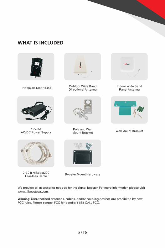
WHAT IS INCLUDED
flfiimgrE
Home 4K SmartLink O-UtdO-Ol'Wlde Band IndoorWIde BandDirectionalAntenna PanelAntenna
_. ’ . . _._.1 _
ii.
12V/3A Pole and WallAC/DC Power Supply MountBracket Wall MountBracket
2*30 ft HiBoostZOOLOW—loss Cable Booster Mount Hardware
We provide all accessories needed for the signal booster. For more information please visitwww.hiboostusa.com.
Warning: Unauthorized antennas, cables, and/or coupling devices are prohibited by newFCC rules. Please contact FCC for details: 1-888—CALL-FCC.
3/18
35#730051"HOW IT WORKS
The HiBoost Home 4K smart link signal booster is designed to help mobile usersimprove signal in homes, offices, and other areas where cellular signal is weakor unreliable. The outdoor antenna receives the signal from the nearest cellulartower, amplifies it, and transmits to the signal booster. Then the indoor antennawill receive the signal and retransmit it to your mobile device. The signalsproduced by your phone are also amplified by the indoor antenna via thebooster and outdoor antenna.This manual provides simple installation instructions that will have your signalbooster kit running in record time.
HOW TO INSTALL YOUR SIGNAL BOOSTER
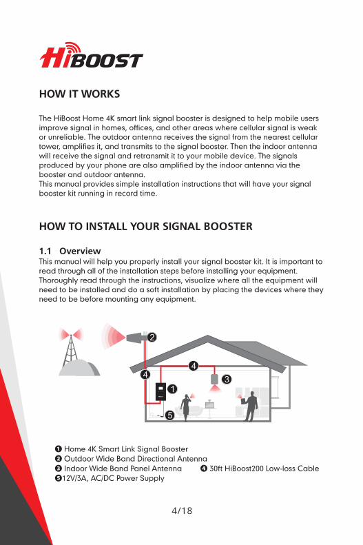
1.1 OverviewThis manual will help you properly install your signal booster kit. It is important toread through all of the installation steps before installing your equipment.Thoroughly read through the instructions, visualize where all the equipment willneed to be installed and do a soft installation by placing the devices where theyneed to be before mounting any equipment.
0 Home 4K Smart Link Signal Booster9 Outdoor Wide Band Directional Antenna9 Indoor Wide Band Panel Antenna 0 50ft HiBoostZOO Low-loss Cable912V/3A, AC/DC Power Supply
4/18
1.2 Installation Preparation
Before you install- Make sure you have sufficient cable length between the proposedoutdoor/indoor antenna location and booster connector.- Make sure the position you install the booster is near to an existing electricaloutlet, well ventilated, and away from excessive heat, moisture, and directsunlight.
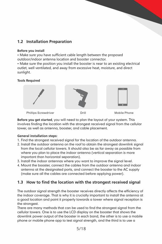
Tools Required
Phillips Screwdriver Drill Mobile Phone
Before you get started, you will need to plan the layout of your system. Thisinvolves finding the location with the strongest received signal from the cellulartower, as well as antenna, booster, and cable placement.
General installation steps:1. Find the strongest received signal for the location of the outdoor antenna.2. Install the outdoor antenna on the roof to obtain the strongest downlink signal
from the local cellular towers. It should also be as far away as possible fromwhere you plan to place the indoor antenna (vertical separation is moreimportant than horizontal separation).
. Install the indoor antennas where you want to improve the signal level.4. Mount the booster, connect the cables from the outdoor antenna and indoor
antenna at the designated ports, and connect the booster to the AC supply(make sure all the cables are connected before applying power).
(N
1.3 How to find the location with the strongest received signal
The outdoor signal strength the booster receives directly affects the efficiency ofthe indoor coverage. That is why it is crucially important to install the antenna ata good location and point it properly towards a tower where signal reception isthe strongest.There are many methods that can be used to find the strongest signal from thecellular towers. One is to use the LCD display on the booster that shows thedownlink power output of the booster in each band, the other is to use a mobilephone or mobile phone app to test signal strength, and the third is to use a
5/18
JH?Baasrcommercially available signal strength meter.We highly recommend that you use the LCD display on the booster as thismethod is generally more convenient. However, in situations where the desiredcarrier's signal is much weaker than the other local signals, using a mobilephone, app, or signal level meter can be a more accurate method of homing inon the best signal for installation.
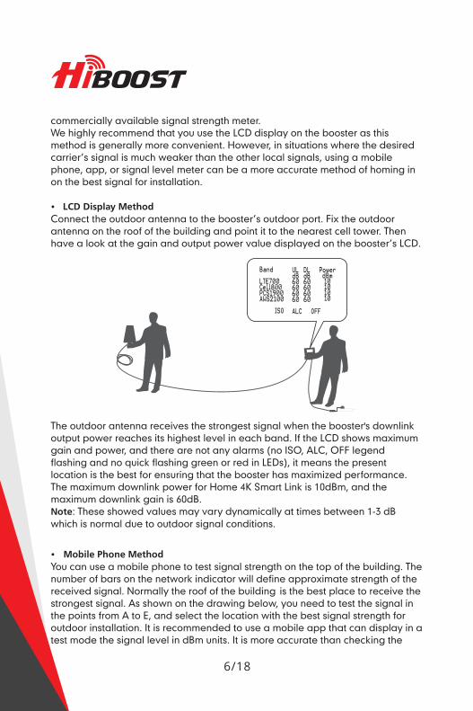
. LCD Display MethodConnect the outdoor antenna to the booster's outdoor port. Fix the outdoorantenna on the roof of the building and point it to the nearest cell tower. Thenhave a look at the gain and output power value displayed on the booster’s LCD.
The outdoor antenna receives the strongest signal when the booster's downlinkoutput power reaches its highest level in each band. If the LCD shows maximumgain and power, and there are not any alarms (no ISO, ALC, OFF legendflashing and no quick flashing green or red in LEDs), it means the presentlocation is the best for ensuring that the booster has maximized performance.The maximum downlink power for Home 4K Smart Link is 10dBm, and themaximum downlink gain is 60dB.Note: These showed values may vary dynamically at times between 1-3 dBwhich is normal due to outdoor signal conditions.
- Mobile Phone MethodYou can use a mobile phone to test signal strength on the top of the building. Thenumber of bars on the network indicator will define approximate strength of thereceived signal. Normally the roof of the building is the best place to receive thestrongest signal. As shown on the drawing below, you need to test the signal inthe points from A to E, and select the location with the best signal strength foroutdoor installation. It is recommended to use a mobile app that can display in atest mode the signal level in dBm units. It is more accurate than checking the
6/18
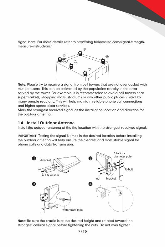
signal bars. For more details refer to http://blog.hiboostusa.com/signal-strength-measure-instructions/.
4GNote: Please try to receive a signal from cell towers that are not overloaded withmultiple users. This can be estimated by the population density in the areaserved by the tower. For example, it is recommended to avoid cell towers nearsupermarkets, shopping malls, stadiums or any other public places visited bymany people regularly. This will help maintain reliable phone call connectionsand higher speed data services.Mark the strongest received signal as the installation location and direction forthe outdoor antenna.
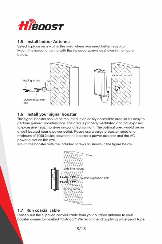
1.4 Install Outdoor AntennaInstall the outdoor antenna at the the location with the strongest received signal.
IMPORTANT: Testing the signal 5 times in the desired location before installingthe outdoor antenna will help ensure the clearest and most stable signal forphone calls and data transmission.
1 to 2 inchdiameter pole
Note: Be sure the cradle is at the desired height and rotated toward thestrongest cellular signal before tightening the nuts. Do not over tighten.
7/18
JH?Baasr1.5 Install Indoor AntennaSelect a place on a wall in the area where you need better reception.Mount the indoor antenna with the included screws as shown in the figurebelow.
slide into mount
tapping screw hook
plastic expansionbolt ’
1.6 Install your signal boosterThe signal booster should be mounted in an easily accessible area so it’s easy toperform general maintenance. The area is properly ventilated and not exposedto excessive heat, moisture and/or direct sunlight. The optimal area would be ona wall located near a power outlet. Please use a surge protector rated at aminimum of 1000 Joules between the booster’s power adaptor and the ACpower outlet on the wall.Mount the booster with the included screws as shown in the figure below.
flii
<1
": "
tapping‘s‘cre‘w
1.7 Run coaxial cableLoosely run the supplied coaxial cable from your outdoor antenna to yourbooster connector marked ”Outdoor.” We recommend applying waterproof tape
8/18
to fully waterproof the connection.Connect the indoor ontenno cables from your indoor antenna to the boosterconnector morked ”Indoor.” Tighten the connection by hand.(After you have tested the system you con permonently secure the coaxialcable).As you route and pull cobling, follow these general guidelines:- Bend cables and route them smoothly, and protect the outer skin ogoinst any
damage.. Keep horizontol cobles straight and fosten them with 0 tie every three to five
feet.. Bind dnd fdsten verticol cobles every six to eight feet.- Woterproof dll connectors between outdoor antenna and coaxial cables with
waterproof tape to ovoid water or other kinds of damage.. Be careful when plugging the connector in so as not to damage the center pins
on the connectors.
1.8 Power up your signal booster
Once all the following precoutions hove been token, power on the signalbooster.1. Verify that you have left at least 20 feet of vertical sepdrotion space between
the indoor and outdoor ontennds.2. Never point the front of outdoor ontenno towards the inside of the indoor
antenna.3. Verify that the supplied coaxial cables from both the outdoor antenna and the
indoor antenna are properly connected to the signal booster beforepowering it up.
4. Carefully plug in the supplied power adaptor into the signal booster where itis marked 'DC 12V' and connect the other end to 0 power outlet.
The LED indicator morked power should light up green.
SIGNAL BOOSTER STATUS
Overview: The booster has 0 smort stortup system. When you have finished thebooster system installation and power on the booster, it will start its initiolizotionprocess to check the received downlink signal from the cell site and the isolationstatus. This on automatic process designed to ensure its best performance. Thiswill take approximately 3-5 seconds.After the booster starts up, please check if the coverage is good. If it is good, thebooster system installation is complete. If the coverage is not adequate, pleosefully reredd and understand the LCD, LED indicotions, control buttons, and MGCfunction on your booster. These will help you identify and solve any potentiolIssues.
9/18
JH?Baasr- LCD Features
I' k D I' kUp 'n own In Indicates the monitoringGa'n_,, Gain , ...................I status through bluetooth
. 0 Indicates the monitoringWorklng Frequency 9""" " status through WiFi?Indicates relative RF .......................... ....Downlink Output Power
power ofdownlinksignal from tower
Indicates thatpower is ON
Antenna IsolationStatus Indicators Band Shut Off Indicator
Automatic Level Control(ALC) Activity Indicator
. Manual Gain Controls(see user manual fordetails)
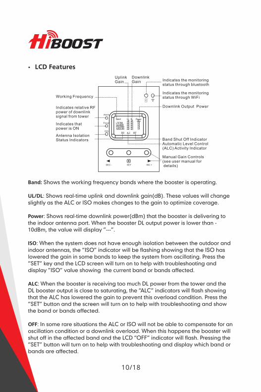
Band: Shows the working frequency bands where the booster is operating.
UL/DL: Shows real-time uplink and downlink gain(dB). These values will changeslightly as the ALC or ISO makes changes to the gain to optimize coverage.
Power: Shows real-time downlink power(dBm) that the booster is delivering tothe indoor antenna port. When the booster DL output power is lower than -IOdBm, the value will display "---”.
ISO: When the system does not have enough isolation between the outdoor andindoor antennas, the ”ISO" indicator will be flashing showing that the ISO haslowered the gain in some bands to keep the system from oscillating. Press the"SET" key and the LCD screen will turn on to help with troubleshooting anddisplay ”ISO" value showing the current band or bands affected.
ALC: When the booster is receiving too much DL power from the tower and theDL booster output is close to saturating, the ”ALC" indicators will flash showingthat the ALC has lowered the gain to prevent this overload condition. Press the"SET” button and the screen will turn on to help with troubleshooting and showthe band or bands affected.
OFF: In some rare situations the ALC or ISO will not be able to compensate for anoscillation condition or a downlink overload. When this happens the booster willshut off in the affected band and the LCD ”OFF” indicator will flash. Pressing the”SET" button will turn on to help with troubleshooting and display which band orbands are affected.
10/18
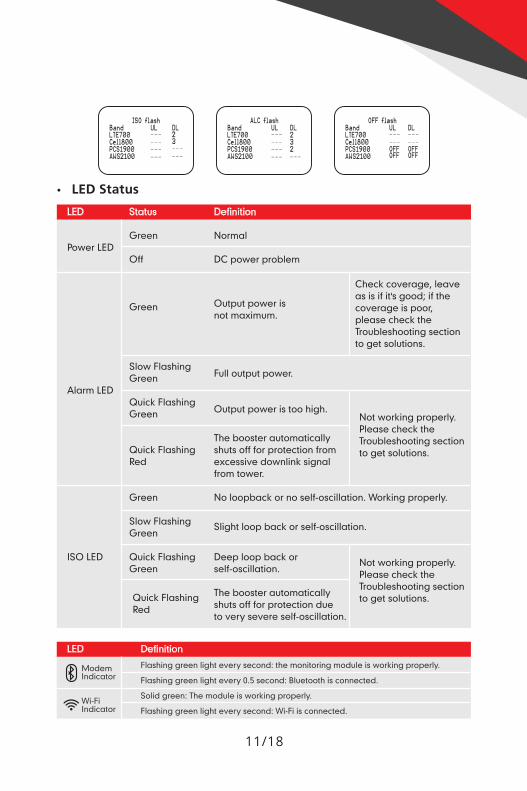
ISO flash ALC flash 0FF {113EBand UL DL Band UL DL BandLTE7B® --- 2 LTETBQ --- 2 LTE7B® --- ---CeHBBB --- 3 Cefl800 --- 3 CeHBEB --- ---PC819BG ——— --- PC819UQ ——— 2 PC81900 OFF OFFAHS21®E ——— ——— AHS2IBB ——— ——— ANS21®B OFF OFF
- LED Status
LED Status Definition
Green NormalPower LED
Off DC power problem
Check coverage, leaveas is if it's good; if thecoverage is poor,please check theTroubleshooting sectionto get solutions.
Output power isnot maximum.
Green
Slow Flashing F llGreen u output power.
Alarm LEDQ ' kFl h'
UIC OS Ing Output power is too high.Green Not working properly.
Please check theThe booster automatically Troubleshooting section
Quick Flashing shuts off for protection from to get solutions.Red excessive downlink signal
from tower.
Green No loopback or no self-oscillation. Working properly.
Slow Flashing Slight loop back or self-oscillation.Green
ISO LED Quick Flashing Deep loop back orGreen self-oscillation. NOt working properly.
Please check theTroubleshooting section
Quick Flashing The booster automatically to get solutions.Red shuts off for protection dueto very severe self-oscillation.
LED DefinitionModem Flashing green light every second: the monitoring module is working properly.
Indicator Flashing green light every 0.5 second: Bluetooth is connected.
Q Wi-Fi Solid green: The module IS working properly.
° Indicator Flashing green light every second: Wi-Fi is connected.
11/18
JH?BaasrControl Buttons Operation and Manual gain control (MGC)
There are 5 operation modes relative to the control keys:. Press the ”SET” key for more than 3 seconds- Short press on the ”SET" key- Short press on the ”DEC-" key- Short press on ”INC+" key. Simultaneously press on the ”DEC-" and ”INC+" keys for more than 3 seconds
Since the booster has a self-adaptive smart automatic level control (ALC) andisolation gain processing (ISO), most of the time manual adjustments are notrequired to achieve good coverage. However, in some cases where the ALC orISO is working at a very high rate to adjust the gain and the Alarm or ISO LED isflashing more than once a second, a manual adjustment might be desired.
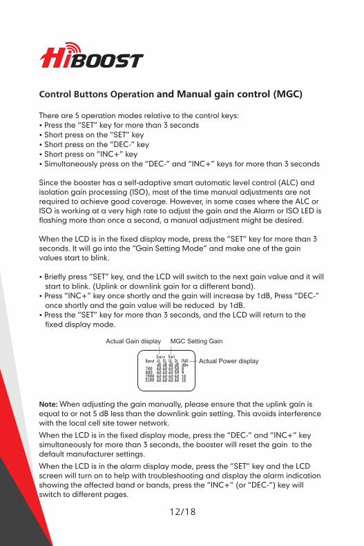
When the LCD is in the fixed display mode, press the ”SET" key for more than 3seconds. It will go into the ”Gain Setting Mode" and make one of the gainvalues start to blink.
. Briefly press ”SET" key, and the LCD will switch to the next gain value and it willstart to blink. (Uplink or downlink gain for a different band).
- Press ”INC+” key once shortly and the gain will increase by 1dB, Press ”DEC-”once shortly and the gain value will be reduced by 1dB.
. Press the ”SET” key for more than 3 seconds, and the LCD will return to thefixed display mode.
Actual Gain display MGC Setting Gain
0:1
:3
:0 Actual Power displayPcl8911
LB89@0Eli?)
Note: When adjusting the gain manually, please ensure that the uplink gain isequal to or not 5 dB less than the downlink gain setting. This avoids interferencewith the local cell site tower network.When the LCD is in the fixed display mode, press the ”DEC-" and ”INC+” keysimultaneously for more than 3 seconds, the booster will reset the gain to thedefault manufacturer settings.When the LCD is in the alarm display mode, press the ”SET” key and the LCDscreen will turn on to help with troubleshooting and display the alarm indicationshowing the affected band or bands, press the ”INC+” (or ”DEC-”) key willswitch to different pages.
12/18
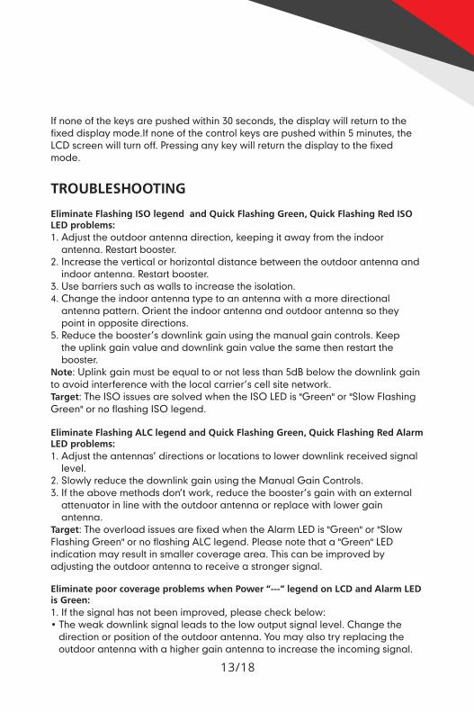
If none of the keys are pushed within 30 seconds, the display will return to thefixed disploy mode.lf none of the control keys ore pushed within 5 minutes, theLCD screen will turn off. Pressing any key will return the display to the fixedmode.
TROUBLESHOOTING
Eliminate Flashing ISO legend and Quick Flashing Green, Quick Flashing Red ISOLED problems:1. Adjust the outdoor ontenno direction, keeping it dy from the indoor
ontenno. Restort booster.2. Increase the verticol or horizontal distance between the outdoor antenna and
indoor ontenno. Restort booster.3. Use barriers such 03 wells to increase the isolation.4. Change the indoor ontenno type to on antenna with o more directionol
ontenno pottern. Orient the indoor ontenno and outdoor ontenno so theypoint in opposite directions.
5. Reduce the booster’s downlink goin using the manual goin controls. Keepthe uplink goin value and downlink goin value the some then restart thebooster.
Note: Uplink goin must be equal to or not less than 5dB below the downlink gointo ovoid interference with the local corrier’s cell site network.Target: The ISO issues are solved when the ISO LED is "Green" or "Slow FloshingGreen" or no floshing ISO legend.
Eliminate Flashing ALC legend and Quick Flashing Green, Quick Flashing Red AlarmLED problems:1. Adjust the ontennos’ directions or locations to lower downlink received signal
level.2. Slowly reduce the downlink gdin using the Manual Goin Controls.3. If the above methods don’t work, reduce the booster’s gain with on external
ottenuotor in line with the outdoor antenna or replace with lower goinontenno.
Target: The overlood issues are fixed when the Alarm LED is "Green" or "SlowFloshing Green" or no floshing ALC legend. Please note that on "Green" LEDindicotion may result in smaller coverage area. This con be improved byadjusting the outdoor antenna to receive (:1 stronger signdl.
Eliminate poor coverage problems when Power legend on LCD and Alarm LEDis Green:1. If the signal has not been improved, please check below:- The weak downlink signol leads to the low output signal level. Change the
direction or position of the outdoor ontenno. You may also try replacing theoutdoor antenna with 0 higher goin antenna to increase the incoming signal.
13/18
35#730051"- Check to see if it is necessary to add more indoor antennas. Barriers such as
walls can block the signal indoors. You should also check the booster to makesure the power is maximized. Try installing more indoor antennas or replacethe booster with a higher powered one.
2. If the signal in a small section of the building hasn't been improved, try thefollowing:
- Check to see if the indoor antenna is installed correctly. Try moving theantenna to improve coverage.
- Try adjusting the direction the indoor antenna is pointing.
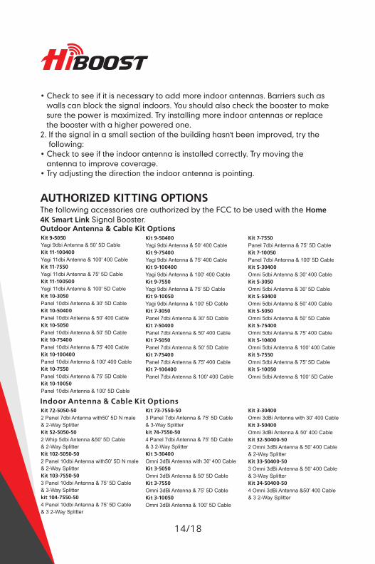
AUTHORIZED KITTING OPTIONSThe following accessories are authorized by the FCC to be used with the Home4K Smart Link Signal Booster.Outdoor Antenna & Cable Kit OptionsKit 9-5050Yagi 9dbi Antenna & 50’ 5D CableKit 11-100400Yagi 11dbi Antenna & 100' 400 CableKit 11-7550Yagi 11dbi Antenna & 75' 5D CableKit 11-100500Yagi 11dbi Antenna & 100' 5D CableKit 10-3050Panel 10dbi Antenna & 30' 5D CableKit 10-50400Panel 10dbi Antenna & 50' 400 CableKit 10-5050Panel 10dbi Antenna & 50' 5D CableKit 10-75400Panel 10dbi Antenna & 75' 400 CableKit 10-100400Panel 10dbi Antenna & 100' 400 CableKit 10-7550Panel 10dbi Antenna & 75' 5D CableKit 10-10050Panel 10dbi Antenna & 100' 5D Cable
Kit 9-50400Yagi 9dbi Antenna & 50' 400 CableKit 9-75400Yagi 9dbi Antenna & 75' 400 CableKit 9—100400Yagi 9dbi Antenna & 100' 400 CableKit 9-7550Yagi 9dbi Antenna & 75' 5D CableKit 9—10050Yagi 9dbi Antenna & 100' 5D CableKit 7-3050Panel 7dbi Antenna & 30' 5D CableKit 7-50400Panel 7dbi Antenna & 50' 400 CableKit 7-5050Panel 7dbi Antenna & 50' 5D CableKit 7-75400Panel 7dbi Antenna & 75' 400 CableKit 7-100400Panel 7dbi Antenna & 100' 400 Cable
Indoor Antenna & Cable Kit OptionsKit 72-5050-502 Panel 7dbi Antenna with50' 5D N male& 2-Way SplitterKit 52-5050-502 Whip 5dbi Antenna &50' 5D Cable& 2-Way SplitterKit 102-5050-502 Panel 10dbi Antenna with50' 5D N male& 2-Way SplitterKit 103-7550-503 Panel 10dbi Antenna & 75' 5D Cable& 3-Way Splitterkit 104-7550-504 Panel 10dbi Antenna & 75' 5D Cable& 3 2-Way Splitter
Kit 73-7550-503 Panel 7dbi Antenna & 75' 5D Cable& 3-Way Splitterkit 74-7550-504 Panel 7dbi Antenna & 75' 5D Cable& 3 2-Way SplitterKit 3-30400Omni 3dBi Antenna with 30' 400 CableKit 3-5050Omni 3dBi Antenna & 50' 5D CableKit 3-7550Omni 3dBi Antenna & 75' 5D CableKit 3-10050Omni 3dBi Antenna & 100' 5D Cable
14/18
Kit 7-7550Panel 7dbi Antenna & 75' 5D CableKit 7-10050Panel 7dbi Antenna & 100' 5D CableKit 5-30400Omni 5dbi Antenna & 30' 400 CableKit 5-3050Omni 5dbi Antenna & 30' 5D CableKit 5-50400Omni 5dbi Antenna & 50' 400 CableKit 5-5050Omni 5dbi Antenna & 50' 5D CableKit 5-75400Omni 5dbi Antenna & 75' 400 CableKit 5-10400Omni 5dbi Antenna & 100' 400 CableKit 5-7550Omni 5dbi Antenna & 75' 5D CableKit 5-10050Omni 5dbi Antenna & 100' 5D Cable
Kit 3-30400Omni 3dBi Antenna with 30' 400 CableKit 3-50400Omni 3dBi Antenna & 50' 400 CableKit 32-50400-502 Omni 3dBi Antenna & 50' 400 Cable& 2-Way SplitterKit 33-50400-503 Omni 3dBi Antenna & 50' 400 Cable& 3-Way SplitterKit 34-50400-504 Omni 3dBi Antenna &50' 400 Cable& 3 2-Way Splitter
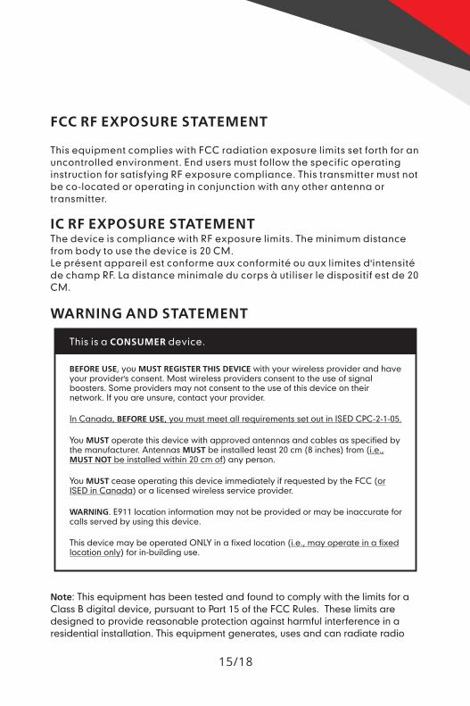
FCC RF EXPOSURE STATEMENT
This equipment complies with FCC radiation exposure limits set forth for anuncontrolled environment. End users must follow the specific operatinginstruction for satisfying RF exposure compliance. This transmitter must notbe co-located or operating in conjunction with any other antenna ortransmitter.
|C RF EXPOSURE STATEMENTThe device is compliance with RF exposure limits. The minimum distancefrom body to use the device is 20 CM.Le présent appareil est conforme aux conformité ou aux limites d'intensitéde champ RF. La distance minimale du corps a utiliser le dispositif est de 20CM.
WARNING AND STATEMENT
This is a CONSUMER device.
BEFORE USE, you MUST REGISTER THIS DEVICE with your wireless provider and haveyour provider's consent. Most wireless providers consent to the use of signalboosters. Some providers may not consent to the use of this device on theirnetwork. If you are unsure, contact your provider.
In Canada, BEFORE USE, you must meet all requirements set out in ISED CPC-2-1-05.
You MUST operate this device with approved antennas and cables as specified bythe manufacturer. Antennas MUST be installed least 20 cm (8 inches) from (Le,MUST NOT be installed within 20 cm of) any person.
You MUST cease operating this device immediately if requested by the FCC (gISED in Canada) or a licensed wireless service provider.
WARNING. E911 location information may not be provided or may be inaccurate forcalls served by using this device.
This device may be operated ONLY in a fixed location (i.e., may operate in a fixedlocation only) for in-building use.
Note: This equipment has been tested and found to comply with the limits for aClass B digital device, pursuant to Part 15 of the FCC Rules. These limits aredesigned to provide reasonable protection against harmful interference in aresidential installation. This equipment generates, uses and can radiate radio
15/18
JH?Baasrfrequency energy and, if not installed and used in accordance with theinstructions, may cause harmful interference to radio communications. However,there is no guarantee that interference will not occur in a particular installation.If this equipment does cause harmful interference to radio or televisionreception, which can be determined by turning the equipment off and on, theuser is encouraged to try to correct the interference by one or more of thefollowing measures:- Reorient or relocate the receiving antenna.- Increase the separation between the equipment and receiver.- Connect the equipment into an outlet on a circuit different from that to which
the receiver is connected.- Consult the dealer or an experienced radio/TV technician for help.
Changes or modifications not expressly approved by HiBoost could void theuser's authority to operate the equipment.Note: For a complete list of antennas and cables approved for use with theseboosters see Authorized Kitting Options page 14.
FCC 27.50(d)(4)Statement: Fixed, mobile, and portable (handheld) stationsoperating in the 1710-1755 MHz band are limited to 1 watt EIRP. Fixed stationsoperating in the 1710-1755 MHZ band are limited to a maximum antenna heightof 10 meters above ground.
FURTHER INFORMATION ON SIGNAL BOOSTER END-USE REGISTRATIONThe following links are the currently active contacts for booster registration withUS. wireless providers.
https://www.uscellular.com/uscellular/support/fcc-booster-registration.jsphttps://www.sprint.com/IegaI/fcc_boosters.htmlhttps://www.verizonwireless.com/solutions-and-services/accessories/register-signal-booster/https://support.t-mobiIe.com/docs/DOC-9827https://securec45.securewebsession.com/attsignalbooster.com/
IC StatementThis device complies with Innovation, Science and Economic DevelopmentCanada ICES-003 Compliance Label: CAN ICES-3 (B)/ NMB-3(B).Le present appareil est conforme Innovation, science et développementéconomique Canada ICES-003 Etiquette de conformité: CAN ICES-5 (B) / NMB-3(B).Link to CPC-2-1-05http://www.ic.gc.ca/eic/site/smt-gst.nsf/eng/sf08942.htm|
16/18
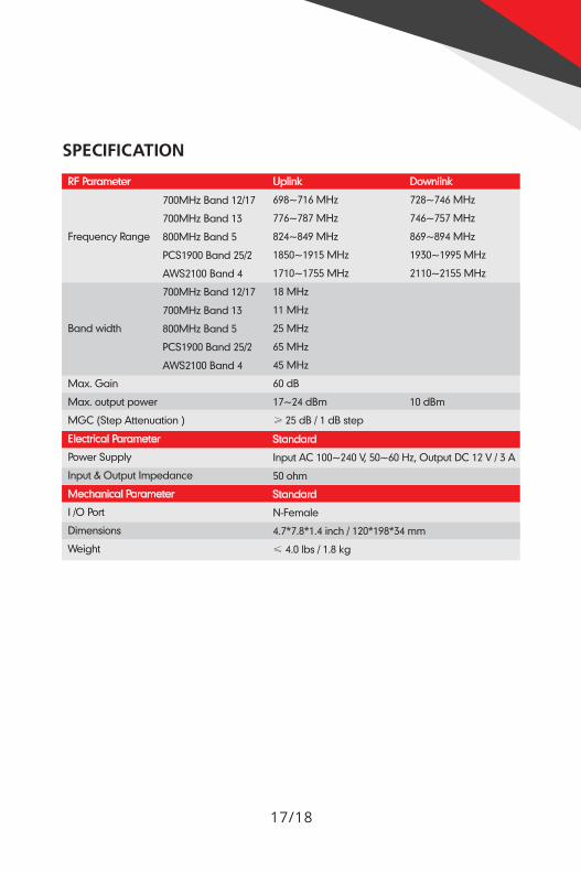
SPECIFICATION
RF Parameter Uplink Downlink
700MHz Band 12/17 698~716 MHz 728~746 MHZ
700MHz Band 13 776~787 MHz 746~757 MHz
Frequency Range 800MHz Band 5 824~849 MHz 869~894 MHz
PCS1900 Band 25/2 1850~1915 MHz 1930~1995 MHz
AW32100 Band 4 1710~1755 MHz 2110~2155 MHz
700MHz Band 12/17 18 MHz
700MHz Band 15 11 MHz
Band width 800MHz Band 5 25 MHz
PCS1900 Band 25/2 65 MHz
AW82100 Band 4 45 MHz
Max. Gain 60 dB
Max. output power 17~24 dBm 10 dBm
MGC (Step Attenuation ) > 25 dB/ 1 dB step
Power Supply Input AC 100~240 V, 50~60 Hz, Output DC 12 V/ 5 A
Input & Output Impedance 50 ohm
I /0 Port N-Female
Dimensions 4.7*7.8*1.4 inch / 120*198*54 mm
Weight < 4.0 Ibs/ 1.8 kg
17/18
J#330051"PRODUCT WARRANTY
30-Day Money-Back: All HiBoost products are protected by a 30-day money-back guarantee. If for any reason the performance of any product is notacceptable, the product may be returned to the reseller with a dated proof ofpurchase.
6-Year Warranty HiBoost signal boosters and kits are warranted for 6 years.Customers can choose to return the signal boosters and kits directly to themanufacturer at the purchaser’s expense with a dated proof of purchase and aReturned Material Authorization (RMA) number supplied by HiBoost.
HiBoost will supply two options: repair or replace. HiBoost will cover the cost ofdelivery for the consumers located within the continental US.
This warranty does not apply to any signal boosters or kits determined byHiBoost to have been subjected to misuse, abuse, neglect, or mishandling thatalters or damages physical or electronic properties. Failure to use a surgeprotected AC power strip with at least a 1000 Joule rating will void yourwarranty. Damage caused by lightning is not covered by this warranty.
All HiBoost products that are packaged with other HiBoost accessory productsare intended for resale and used as a single integrated system. Such productkits are required to be sold to the end users or subsequent reseller as packaged.RMA numbers may be obtained by contacting Technical Support at 972-870-5666.
18/18


HiBoost USA
6210 N Belt Line Rd., Ste. 110, Irving, TX 75063Phone/Fax: (972) 870-5666
E-mail: [email protected]: www.hiboostusa.com


